Motori Elettrici Autofrenanti - Bermar.it
Motori Elettrici Autofrenanti - Bermar.it
Motori Elettrici Autofrenanti - Bermar.it

Create successful ePaper yourself
Turn your PDF publications into a flip-book with our unique Google optimized e-Paper software.
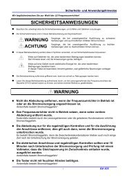
Decremento coppia di frenatura<br />
Braking torque decreasement<br />
*Giri della ghiera di regolazione<br />
B16<br />
*Revolution of the adjustment ring<br />
08.006-4-0361<br />
Motor size Grandezza<br />
J W Rmax W RO,1 P Rmax g min X n t 1 t 21 = t 21 ~<br />
Size<br />
[kgm 2 ] [J] [J] [J/s] [mm] [mm] [ms] [ms] [ms]<br />
56 00 0,010x10 -3 0,6x10 3 3,50x10 6 28 - - 35 12 60<br />
63 01 0,018x10 -3 0,8x10 3 5,11x10 70 5,0 0,4 40 20 45<br />
71 02 0,025x10 -3 1,0x10 3 7,50x10 6 84 5,5 0,4 45 10 32<br />
80 03 0,072x10 -3 1,6x10 3 12,50x10 6 100 6,5 0,5 55 15 50<br />
90 04 0,136x10 -3 2,1x10 3 19,10x10 6 130 8,0 0,6 90 20 95<br />
100 05 0,352x10 -3 3,8x10 3 28,00x10 6 200 10,0 0,6 100 40 200<br />
112/132 06 0,561x10 -3 6,5x10 3 28,80x10 6 250 10,0 1,0 160 60 330<br />
160 07 3,402x10 -3 11,0x10 3 35,70x10 6 266 10,0 1,0 200 70 650<br />
160 08 7,169x10 -3 20,0x10 3 44,20x10 6 330 11,0 1,2 280 70 800<br />
Dati tecnici<br />
J = momento di inerzia del mozzo e del ferodo<br />
W Rmax = lavoro di attr<strong>it</strong>o consent<strong>it</strong>o per ogni frenata<br />
W RO,1 = lavoro di attr<strong>it</strong>o per un’usura di mm 0,1<br />
P Rmax = lavoro di attr<strong>it</strong>o per secondo<br />
g min = spessore minimo consent<strong>it</strong>o del ferodo<br />
X n = traferro nominale<br />
t 1 = r<strong>it</strong>ardo di chiusura<br />
t 21 = = tempo di disinserimento con comando<br />
in corrente continua<br />
t 21 ~ = tempo di disinserimento con comando<br />
in corrente alternata<br />
I valori W Rmax e W RO,1 sono stati determinati mediante prove<br />
e applicati ad operazioni senza dischi di frizione. Veloc<strong>it</strong>à,<br />
momento di inerzia e frequenza di sw<strong>it</strong>ching sono stati<br />
attentamente selezionati per raggiungere la temperatura<br />
massima consent<strong>it</strong>a per il funzionamento.<br />
I tempi di manovra indicati (t 1 e t 21 ) valgono per il traferro<br />
(X) ed il momento torcente (M 2N ). Questi valori sono medi:<br />
eventuali variazioni possono dipendere da dispersioni nel<br />
sistema di alimentazione e dalla temperatura della bobina.<br />
Technical Data<br />
J = moment of inertia of hub and lining<br />
W Rmax = permissible friction per braking<br />
W RO,1 = friction until 0,1 mm wear is reached<br />
P Rmax = permissible friction work per second<br />
g min = min. permissible lining thickness<br />
X n = clearance, at which a readjustment is<br />
recommended<br />
t 1 = closing delay<br />
t 21 = = sw<strong>it</strong>ch-off time at d.c.-side sw<strong>it</strong>ching operations<br />
t 21 ~ = sw<strong>it</strong>ch-off time at d.c.-side sw<strong>it</strong>ching operations<br />
The values W Rmax and W RO,1 were determined through tests<br />
and apply to operation w<strong>it</strong>hout friction discs. Speed,<br />
moment of inertia and sw<strong>it</strong>ching frequency were carefully<br />
selected to attain the maximum permissible operating<br />
temperature. Depending on the actual application these<br />
values may be exceeded.<br />
The specified sw<strong>it</strong>ching times (t 1 e t 21 ) apply to nominal<br />
clearance (X) and nominal torque (M 2N ). It concerns average<br />
values whose dispersion depends on the manner of<br />
rectification and coil temperature.<br />
70