New micro size drive STARVERT - Bermar.it
New micro size drive STARVERT - Bermar.it
New micro size drive STARVERT - Bermar.it

You also want an ePaper? Increase the reach of your titles
YUMPU automatically turns print PDFs into web optimized ePapers that Google loves.
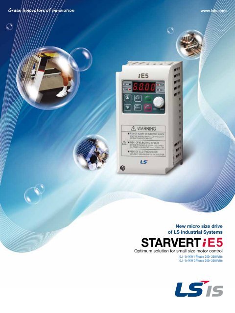
www.lsis.com<strong>New</strong> <strong>micro</strong> <strong>size</strong> <strong>drive</strong>of LS Industrial Systems<strong>STARVERT</strong>Optimum solution for small <strong>size</strong> motor control0.1~0.4kW 1Phase 200~230Volts0.1~0.4kW 3Phase 200~230Volts
Small but Powerful!We have created the Micro class <strong>drive</strong> to providethe optimal solution for small <strong>size</strong> motor controls.You will be experiencing amazing power w<strong>it</strong>h this slim <strong>size</strong>.<strong>STARVERT</strong>
Slim and variety!Our iE5 is best f<strong>it</strong> for small machineriessuch as packing machines, small conveyers, treadmills and etc...Smaller <strong>micro</strong> <strong>size</strong>Our iE5 realizes 5% smaller <strong>micro</strong> <strong>size</strong> comparing to previous product.Easy operation and controlThe operation became easy by adopting the 6 keys and volume resistor typeson the loader. Besides, convenience is guaranteed by lim<strong>it</strong>ing the total numberof parameters as 100 parameters.15%Light on in ed<strong>it</strong>ing modeLight on in <strong>drive</strong> operationLight on in forward operationLight on in reverse operation128mmUse to change operation frequencyUse for <strong>drive</strong> operationA reset key when the stop key is fault during <strong>drive</strong> operation68mmSV002 iE5-185mm*For 400W modelUse between group shifts or parameter setting.This key moves to the left the dig<strong>it</strong> pos<strong>it</strong>ionUse parameter set value change and saveUse for code shifts and parameter set value increase4 _Use for code shifts and parameter set value decrease
PI ControlModbus communication interface (optional)(optional)60HzPI ControlV/F ControlThe PI Control is used to control theoil level, temperature and pressure ofplant and process.This <strong>drive</strong> speedcontrol function compares between<strong>drive</strong> setting value and signal valuesgauged from sensors and actualcontrol is made through Proportionand Integral.Modbus-RTUThe optional modbus communicationenables controlling <strong>drive</strong>s throughPLC and other controlling devices.PNP, NPN dual control SignaliE5 provides both PNP and NPNminor signal powers so that nomatter what signal type the externalcontroller adopts, +24V power canbe applied.Parameter copy function (Under development)(Under development)Copy Copy The parameters inputed to a <strong>drive</strong>can be duplicated and copied to other<strong>drive</strong>s by this parameter copy un<strong>it</strong>.<strong>STARVERT</strong> iE5 _ 5
Model and Specifications0.1kW(1/8HP)SV001 iE5-1SV001 iE5-20.2kW(1/4HP)SV002 iE5-1SV002 iE5-20.4kW(0.5HP)SV004 iE5-1SV004 iE5-2C : RS-485 communication is available as option- : RS-485 communication is not availableInput voltage1 : Single 220V class2 : 3Phase 220V classLS Drive Starvert seriesMaximum motor capac<strong>it</strong>y(kW)(001 : 0.1kW ~ 004 : 0.4kW)LS Drive series nameDrive modelInput voltage specificationOutput voltage, Rated output current, Frequency,Drive capac<strong>it</strong>yBarcode and serial number6 _
<strong>New</strong> <strong>micro</strong> <strong>size</strong> <strong>drive</strong><strong>STARVERT</strong>Standard Specification▒ Basic specificationModel : SV iE5 - 001-1 002-1 004-1 001-2 002-2 004-2[HP]Applicable motor[kW]Rated capac<strong>it</strong>y [kVA]Rated current [A]Rated outputOutput frequency [Hz]Output voltage [V]Applicable voltage [V]Rated input Input frequency[Hz]Rated current [A]1/80.10.30.81/40.20.61.41/20.40.952.51/80.10.30.81/40.20.61.61/20.41.143.00 ~ 200 [Hz]3 phase 200 ~ 230V1 phase 200 ~ 230 VAC (±10%) 3 phase 200 ~ 230 VAC (±10%)50 ~ 60 [Hz] (±5%)2.03.55.51.22.03.5▒ Control▒ OperationControl typeV/F ControlOperationOperation method can be selected betweenFrequency setDig<strong>it</strong>al command : 0.01Hzmethodloader, terminal and communication operationresolutionAnalog command : 0.06Hz (Max.frq : 60Hz)Dig<strong>it</strong>al command :Frequency setAnalog method : 0~10(V), 0~20(mA), Loader volumeDig<strong>it</strong>al method : LoaderFrequency accuracy0.01% of Max. Output frequencyAnalog command :OperationfunctionPI Control, Up-Down , 3-wire operation0.1% of Max. Output frequencyNPN / PNP SelectableV/F patternLinear, Squared, User V/FOverload capac<strong>it</strong>y 150% / 1MinTorque boost Manual / Auto torque boost*Note1) The standard of rated capac<strong>it</strong>y is 220V.*Note2) The maximum output voltage does not increase over input voltage and the outputvoltage can be set below input voltage level.InputMultifunctionterminal (5points)P1,P2,P3,P4,P5FWD/REV operation, Fault reset, Jog operation, Multistepfrequency(up/down), DC braking in stop mode,Frequency increase, Frequency decrease, 3 wireoperationexternal trip A and B, Shift to generaloperation from PI operation. Analogue commandfrequency set, Up/down save frequency deleteMultifunctionrelayterminalFault and <strong>drive</strong> operation cond<strong>it</strong>ion output(N.). N.C) AC250V below 0.3A and below DC 30V 1AAnalogueoutput0~10Vdc(below 10mA) : can be selected amongfrequency, current, voltage, DC voltage▒ Protection▒ Guaranteed operation cond<strong>it</strong>ionTripOver voltage, Under voltage, Over current, Ground fault,Drive overload, Overload trip, Overheat, Condensoroverload, Phase loss overload protection, Frequencycommand loss, Hardware faultCoolingEnclosureAmbient temperatureProtection temperatureOpen coolingIP20 (open type)-10℃ ~ 65℃-20℃ ~ 65℃AlarmStall preventionHumid<strong>it</strong>yBelow 90% RH (non-condensation)Momentarypower lossBelow 15msec : Operation continued (should be w<strong>it</strong>hinrated input voltage and rated output)Over 15msec : Auto re-ign<strong>it</strong>ion operation.Alt<strong>it</strong>ude/VibrationInstallation cond<strong>it</strong>ionBelow 1000m, 5.9m/sec square (0.6G)No corrosive gas, No flammable gas, Nooil mist, No dust<strong>STARVERT</strong> iE5 _ 7
Wiring*Note4)*Note1)*Note2)Analogue output*Note3)*Note1) “●”and “ ”means the main circu<strong>it</strong> and the control circu<strong>it</strong> respectably.Please connect to the R and S terminals in case of single phase use.*Note2) The analogue output is from zero to 10V.*Note3) The voltage current and loader volume is possible for the external speed command.*Note4) The P and PI terminals for DC reactor are connected as short circu<strong>it</strong>.8 _
<strong>New</strong> <strong>micro</strong> <strong>size</strong> <strong>drive</strong><strong>STARVERT</strong>Terminal FunctionTerminal signal Terminal name DescriptionR, S, TDC inputConnect 3 phase AC powerMain circu<strong>it</strong>U, V, WP, P1Drive outputDC reactor connectionConnect 3 phase induced motorConnect DC reactor.GGroundGround connection terminal*Note) Please connect to the R and S terminals for single phase <strong>drive</strong>.Classification Terminal signal Terminal name DescriptionInput signalP1, P2, P3,P4, P5VRMultifunction input terminalFrequency set powerFactory default value P1 (FX : forward operation) P2 (RX : Reverse operation)P3 (EST : Emergency stop) P4 (RST : Trip clear signal)P5 (JOG : Jog frequency operation)Analog frequency set power. Max, output is +12V 100mA.AIFrequency set(Volt/Current)DC 0~10V and DC 4~20mA can be set as basic frequency.CMFrequency set common terminalAnalog frequency set signal and AM common terminal.Among output frequency, output current and output voltage, one <strong>it</strong>em canAM-CMDisplaybe selected as output. Factory set is output frequency.Output signalMax output voltage is 0~10V. (Below 10mA)30A, 30C, 30BMultifunctional relayDrive protection function is activated as blocking the output andreleasing multifunction signal. AC 250V below 0.3A and below DC 30V 1A.Loader FunctionClassification Display Function Function descriptionFWDForwardLight is on w<strong>it</strong>h forward operation.REVReverseLight is on w<strong>it</strong>h reverse operation.LEDSETOn settingLight is on when parameter is being set.RUNOn operationLight is off when the <strong>drive</strong> is on Acc/Dcc and on w<strong>it</strong>h normalspeed operation.▲Up keyFor code shift or increasing parameter set value.NPN▼Down keyFor code shift or decreasing parameter set value.RUNOperation keyFor <strong>drive</strong> operationPNPSTOPStop/ResetStop command key during operation and also used as faultclear key.Current inputVolt inputKEYFUNCSHFTFunction keyShift keyUsed for changing parameter set value and saving <strong>it</strong>s valueShift between groups and parameter setting ormoving dig<strong>it</strong> number to the left.Volume resistorNPN/PNP selection sw<strong>it</strong>chCurrent/Voltage selectionsw<strong>it</strong>chFor changing operation frequency.Turning to e<strong>it</strong>her NPN or PNP mode.Sw<strong>it</strong>ch for transforming the analog sw<strong>it</strong>ch inputs into currentor voltage.<strong>STARVERT</strong> iE5 _ 9
Shifts between each code and group▒ Diagram of function code shift methodThe parameter group of iE5 consists of below two groupsGroup nameOperation groupProgram groupContentBasic parameters for operationsuch as the Target frequency,Acc/Dec time and etc.Add<strong>it</strong>ional function set parameter● Shifts between groups can be enabled pressing the shift key at the zero code of the operationand program groups.*Note)*Note) The target frequency can be set at the first group of operation groupso that the factory default value has been set as 0.0 yet in case of frequency change, the changed frequency is displayed.● If a user presses the shift key out of number 0, the activating parameter shifts to 0and if the user presses once more the shift key can be shifted between groups.10 _
<strong>New</strong> <strong>micro</strong> <strong>size</strong> <strong>drive</strong><strong>STARVERT</strong>Shifts between each code and group▒ Operation group code shifts● The first code 0.0 of operation group● Press the up key ▲● The second code ACC of operation group● Press the up key ▲● The third code dEC of operation group● Keep pressing the up key ▲● The last code drC of operation group● Pressing the up key ▲ once again● Back to the first code of the operation group● Pressing the down key ▼ enables to shift reverse direction▒ Setting the operation group frequency to 30.05Hz (Keypad operation)❶● Displays the first code information of theoperation group● Press the function key (FUNC)❺● The third last dig<strong>it</strong> is changed as 0● Set as 3 by pressing the up key ▲❷● The setting light is off● The second decimal point number can bechanged● Keep pressing the up key ▲ till thenumber reaches to 5❻● Press the function key (FUNC)❸● Press the shift key● The set number pos<strong>it</strong>ion shifts to left❼● Left displayed 30.05 blinks and asksif <strong>it</strong> has to be saved● Press the function key (FUNC)❹● The set number pos<strong>it</strong>ion shifts to left● Press twice the shift key❽● The setting light (SET) is off● Saved target frequency is displayedafter stopping the light blink● The saved data parameter is cancelled bypressing the Shift key (SHIFT), up key ▲and then the down key ▼*Note) The saved parameter can be cancelled by pressing all keys except the function key (FUNC).<strong>STARVERT</strong> iE5 _ 11
Parameter Descriptions▒ Operation groupDisplayFunction Setting range Description Factory default Mode changeduring run0.0 Command frequency0 ~ 200 [Hz]Operation frequency set.Displays the command frequency during stop mode anddisplays the output frequency during run In case of multi-speedoperation, the frequency will be zero speed.The frequency setting can not be set over the maximumfrequency(P16).0.0ACC Acceleration time5.00 ~ 6000 [sec] Zero times acc/dec time in case of multi-step speed acc/dec.dEC Acceleration time10.00 Operation using the RUN key and the STOP key of loaderdrvOperation commandmethod 0 ~ 312TerminaloperationFX : Forward operation commandRX : Reverse operation commandFX : Operation and Stop commandRX : Selecting reverse1 X3 Communication operation: Operation by communication0Loader dig<strong>it</strong>al frequency setting 1Dig<strong>it</strong>al1Loader dig<strong>it</strong>al frequency setting 2FrqFrequency settingmethod0 ~ 42Terminal AI input0 X3 AnalogLoader volume resistor4Communication optionSt1 Multi step frequency 1 Speed 1 frequency set in case of multi step operation 10.0St2 Multi step frequency 2 0 ~ 200 [Hz] Speed 2 frequency set in case of multi step operation 20.0St3 Multi step frequency 3 Speed 3 frequency set in case of multi step operation 30.0CUr Output current -Output current display - -rPM No of times of motor spin -Displaying no of time of motor spin(RPM) - -dCL Drive DC voltage -Displaying the DC link voltage of <strong>drive</strong> inside - -vOL Output voltage -Displaying output voltage vOL -nOn Fault status -Displaying the trip type, frequency, current and operation cond<strong>it</strong>ion of trip - -Setting the operation command method as 0drCSpin direction selectionF, rFrForward operationReverse operationP▒ Program group*Note1)DisplayP0P1P2P3P4P5P6P7P8P9Function Setting range Description Factory default Mode changeduring runJump code0 ~ 88Shifting code number set1Fault history 1Fault history 2Fault history 3Fault history deleteForward/Reverse notallowedAcceleration patternDeceleration patternStop mode selectionDC braking frequency---0 ~ 10 ~ 20 ~ 10 ~ 20.1 ~ 60 [Hz]Fault type and frequency, current, acc/dec and stopcond<strong>it</strong>ion of fault.The latest fault is saved as fault history no 1.Deleting the fault history P1~P30 Forward/Reverse spining is possible1 Forward spinning not allowed2 Reverse spinning not allowed0 Liner pattern operation1 S shape pattern operation0 Deceleration stop1 DC braking stop2 Free run stopDC braking start frequency.DC braking frequency can not be set below the startingfrequency P18.nOn -nOnnOn00 X0 X0 X5.0 X--12 _
<strong>New</strong> <strong>micro</strong> <strong>size</strong> <strong>drive</strong><strong>STARVERT</strong>Parameter Descriptions▒ Program group*Note1)DisplayP10P11P12P13P14P15P17P18Output block time beforeDC brakingDC braking volumeDC braking timeDC braking volume atign<strong>it</strong>ionDC braking time of ign<strong>it</strong>ionJog frequencyStandard frequencyStarting frequency0 ~ 60 [sec]0 ~ 200 [%]0 ~ 200 [%]0 ~ 60 [sec]0 ~ 200 [Hz]30 ~ 200 [Hz]0.1 ~ 10 [Hz]Output is blocked for set up time and starts DC braking.DC current <strong>size</strong> that flows to motor.The standard is motor rated current (P43).DC time that flows to motor.DC current volume that flows to motor before <strong>it</strong> spins.Motor rated current (P43).DC current flows to motor for scheduled time at ign<strong>it</strong>ion.Jog operation frequency can be set.The frequency can not be set over maximum frequency(P16).0 XFrequency setting related maximum value of parameters.The standard frequency of Acc/Dec lean.P16 Maximum frequency 40 ~ 200 [Hz] ☞Note : Once the maximum frequency value is changed, all parameter 60.0 Xvalues other than P17(standard frequency) are changed as themaximum frequencies that are all over the maximum frequencies.0 Manual torque boostP19 Torque boost selection 0 ~ 10 X1 Automatic torque boostP20P21Function Setting range Description Factory default Mode changeduring runForward operationtorque boostReverse operationtorque boost0 ~ 60 [sec]0 ~ 15 [%]0 ~ 15 [%]The output frequency w<strong>it</strong>hin which the <strong>drive</strong> output equals to therated voltage of motor.The minimum parameter value of frequency level.The boost volume, in case of forward operation, that flows to motor.In case of maximum output voltage.The boost volume, in case of reverse operation, that flows to motor.The maximum output voltage is standard.0.1 X50 X1.0 X50 X10.060.0 X0.5 X5 X5 X0 LinerP22 V/F pattern 0 ~ 10 X1 SquareP23 Output voltage control 40 ~ 110 [%]Output voltage <strong>size</strong> control. The input voltage is standard.100 XBlocking the <strong>drive</strong> output in case of overload.P24 Overload trip selection 0 ~ 11The overload protection function is activated if user sets as umber 1.Overload current <strong>size</strong> setting.P25 Overload trip level 50 ~ 200 [%]180Motor rated current (P43) is standard.P26P27P28Overload trip timeStall preventionselectionStall prevention level0 ~ 60 [sec]b<strong>it</strong> 2 b<strong>it</strong> 1 b<strong>it</strong> 00 ~ 701234567----vvvv--vv--vv-v-v-v-v0X30 ~ 150 [%]Drive blocks output if the overload trip level(P25) current flows for theoverload trip time.Decelerating in acceleration or normal operation.Deceleration is stopped during deceleration operation.Stall preventionduring decelerationStall preventionduring normaldecelerationStall preventionduring accelerationdecelerationDisplaying the stall prevention current <strong>size</strong> during acceleration ornormal operation in terms of percent(%).The motor rated current(P43) is standard.60150XP29Up/Down frequencysave selection0 ~ 1Selecting the set frequency for up/down operation.If user chooses number 1, <strong>it</strong> is saved onto up/down frequency(P30).0XP30Up/Down frequency save-Displaying up/down operation stop or before acceleration frequency.0.00-P31Dwell frequency0.1 ~ 200 [Hz]Once operation command is inputted, first outputs the dwell frequencyduring dwell time(P32) and then starts acceleration.Dwell value can be set between the maximum frequency P16and starting frequency P18.5.0XP32Dwell time0~10 [sec]Dwell operation time setting0.0X*Note1) The P8 has to be set as 1 (DC braking stop)<strong>STARVERT</strong> iE5 _ 13
Parameter Descriptions▒ Program groupDisplayP33Function Setting range Description Factory default Mode changeduring runSetting the fault detect <strong>it</strong>em as per user selection.The input/output phase loss, ground detect during run can be selected.User selection faultdetect0 ~ 7 [b<strong>it</strong>]User selectionfault detect [Trip]01234567Ground detectduring run GCtInput phase lossdetect CoLOutput phaseloss detect(Pot)b<strong>it</strong> 2 b<strong>it</strong> 1 b<strong>it</strong> 0-vvvv-vvvv-vvvv0P34Selecting start w<strong>it</strong>hpower input0 ~ 1P34 is only used in case the operation command method is selected.E<strong>it</strong>her terminal number 1 or 2. Acceleration is getting startedwhen the FX or RX terminal is on w<strong>it</strong>h power input.0XP35Selecting start after trip0 ~ 1P34 is only used in case the operation command method is selectede<strong>it</strong>her terminal number 1 or 2.In the cond<strong>it</strong>ion that the FX and RX terminals are on, aftertrip, resetting starts acceleration.0While motor is on spining, this function prevents the probable faults.Starting w<strong>it</strong>hpowerinput(P34)Restart afterinstant powerfailureOperation aftertrip (P35)GeneralAccelerationP36P37Speed search selectionSpeed searchcurrent level0 ~ 15 [b<strong>it</strong>]80 ~ 200 [%]b<strong>it</strong> 3 b<strong>it</strong> 2 b<strong>it</strong> 1 b<strong>it</strong> 00123456789101112131415--------vvvvvvvv----vvvv----vvvv--vv--vv--vv--vv-v-v-v-v-v-v-v-vThe current <strong>size</strong> during speed search operation is lim<strong>it</strong>ed.Motor rated current(P43) is standard.0100P38Number of times ofAuto-restart0 ~ 10Setting number of times that <strong>drive</strong> can operate automaticallyafter trip.If trips exceed the set times, <strong>drive</strong> does not restart automatically. Onlyuse when the operation command method(drv) ofoperation group is selected e<strong>it</strong>her terminal umber 1 or 2and the operation command is inputted.However, the Auto-restart does not work in case the protectivefunctions such as OHT, LVT, EST and HWT are in active.0P39Auto re-start stand bytime after trip0 ~ 60 [sec]Re-start is operated after the auto re-start stand-bytime of trip.P40 Motor capac<strong>it</strong>y selection 0.1 ~ 0.4- *Note2) XP41 Number of poles of motor 2 ~ 12Used for number of spining times of motor of the operation group.4X1.014 _*Note2) The in<strong>it</strong>ial value of P40 is set for the <strong>drive</strong> capac<strong>it</strong>y.
<strong>New</strong> <strong>micro</strong> <strong>size</strong> <strong>drive</strong><strong>STARVERT</strong>Parameter Descriptions▒ Program groupDisplayP42P43Motor ratingSlip frequencyMotor rated currentFunction Setting range Description Factory default Mode changeduring run0 ~ 10 [Hz]0.0 ~ 25.5 [A]The difference value between input power frequency and motor nameplate displayed rated spin times(rpm) is inputted.The printed rated current value of name plate is inputted.- *Note3)-XXP44Non-load current ofmotor0.0 ~ 25.5 [A]After taking out load from motor, the current value which was measuredin operation cond<strong>it</strong>ion of rated spin times is inputted.-XP45Carrier frequency selection1 ~ 10 [kHz]As the set carrier value is larger the noise is smaller but the leakingcurrent is bigger.3P46P47P48P50P51P52Control typeselectionPI control P gainPI control I timePI control F gainPI frequencyhighest lim<strong>it</strong>PI frequencylowest lim<strong>it</strong>0 ~ 20 ~ 999.9 [%]0.1~32.0 [sec]0 ~ 99.99 [%]0.1 ~ 200 [Hz]0.1 ~ 200 [Hz]012V/F controlSlip compensation controlPI controlGain setting for PI control response.Feed forward of PI controlLim<strong>it</strong>s the frequency <strong>size</strong> that comes from PI calculation.The setting value can be between the maximumfrequency(P16) and starting frequency(18).0300.01.00.060.05.0XFirst displayed <strong>it</strong>ems on the loader w<strong>it</strong>h power input.P53Power input displayselection0 ~ 15P54Gain of number of timesof motor1 ~ 1000 [%]P55 Constant number of AI filter input 0 ~ 9999P56 Minimum input of AI0 ~ 100 [%]P57AI input maximumvoltage matching0 ~ 200P58 AI maximum input0 ~ 100 [%]P59AI input maximumvoltage matching frequency0 ~ 200 [Hz]P60 Volume input filter constant 0 ~ 9999P61 Volume input minimum value 0 ~ 100 [%]P62Volume input maximum voltagematching frequency0 ~ 200 [Hz]P63 Volume input maximum value 0 ~ 100 [%]P64Volume input maximum voltagemachine frequency0 ~ 200 [Hz]Phase loss standardP65 selection of analog0 ~ 2speed command0 Operation frequency1 Acceleration time2 Deceleration time3 Operation command method4 Frequency command method5 Multi-step frequency 16 Multi-step frequency 27 Multi-step frequency 38 Output current (Cur)9 Number of times of motor spin(rpm)10 Drive DC voltage (DCL)11 User selection (vOL)12 Fault status 113 Operation direction selection14 Output current display15 Displaying number of times of motor spinBy calculating the gear rate of load system, displays the numberof times of motor. Mon<strong>it</strong>oring is possible at the (rPM) code.Controlling the analog input response.Minimum analog input value can be set as % of total input.Analog input minimum case frequency.The maximum analog input value can be set as all input percent(%).The maximum frequency value of analog input.Response speed control of volume input operation.The volume input minimum spin value can be set as all input percent(%).Volume input minimum value frequency.The volume input maximum value can be set as all input percent(%).The volume input maximum value frequency.012No operationOperation below half value of setOperation below set value01001000.010060.01000.010060.00*Note3) All the values from P42 and P44 are modified to adopt the motor capac<strong>it</strong>y P40.<strong>STARVERT</strong> iE5 _ 15
Parameter Descriptions▒ Program groupDisplayP66P67P68P69P70P71P72P73P74Function Setting range Description Factory default Mode changeduring runMulti-function inputterminal P1 functionMulti-function inputterminal P2 functionMulti-function inputterminal P3 functionMulti-function inputterminal P4 functionMulti-function inputterminal P5 functionsInput terminal statusdisplayMulti-function input filterconstantAnalog output <strong>it</strong>emselectionAnalog output level control0 ~ 241 ~ 200 ~ 310 ~ 200 [%]0123456789101112131415160123Forward operation command(FX)Reverse operation command(RX)Emergency stop(EST-Emergency stop trip) : Temporal outputblock.Fault reset (RST)Jog operation command (JOG)Multi-step frequency-upMulti-step frequency-down----DC braking command---Up-down operation Frequency upfunctionFrequency down17183-wire operation.External trip signal input : A contact (EtA)19 External signal input : B contact (EtB)2021222324Changing operation mode from PI to normal operation.Changing operation mode from option operation to master operation.Analog command frequency fixAcc/Dec stop commandUp/Down frequency deleteBIT4 BIT3 BIT2 BIT1 BIT0P5P4P3P2P1Bigger setting value resets in slower response speed.Output <strong>it</strong>emOutput frequencyOutput currentOutput voltageDrive DC voltage10V is standardMatching output 10[V]Maximum frequency150%282VDC 400V01234- -150100P75P76Detected frequencyDetectable frequency range0 ~ 200 [Hz]Please use when the output terminal function of relay output(P77) ischosen from 0~4.No more than the maximum frequency(P16) can be set.0FDT-130.010.01FDT-22FDT-33FDT-44FDT-55Overload (OL)6Drive overload (IOLt)P77Multifunctional relayterminal functionselection0 ~ 1778910Motor stall (STALL)Overvoltage fault (OVt)Low voltage fault (LVt)Cooling pin overheat (OHt)1711Command loss12On operation13On stop14On normal operation15Speed search function is on16Operation command is ready17Fault output selection16 _
<strong>New</strong> <strong>micro</strong> <strong>size</strong> <strong>drive</strong><strong>STARVERT</strong>Parameter Descriptions▒ Program groupDisplayP78P79P80Function Setting range Description Factory default Mode changeduring runAfter trip, when thenumber of Autorestart is set, P38 isactivatedExcept low voltagetrip, in all other casesthis function isactivatedThis function isactivated w<strong>it</strong>h lowvoltage tripb<strong>it</strong> 2 b<strong>it</strong> 1 b<strong>it</strong> 00---1--vFault output selection 0 ~ 7 [b<strong>it</strong>]2-v-3-vv4v--5v-v6vv-7vvvDrive channel 1 ~ 250 Use w<strong>it</strong>h communication optionCommunication speed set0 2400 [bps]Communication speed 0 ~ 21 4800 [bps]2 9600 [bps]212P81Operation type selectionwhen the speedcommand is lost0 ~ 2This function is used when the analog signal of terminal(Volume or AI) or communication are operated by frequency command.01Operating before command loss frequencyFree run stop(Blocking output)02Deceleration stopP82Speed command lossdetermination time0.1 ~ 120 [sec]If the frequency command is not inputted during speed commandloss determination time the <strong>drive</strong> is operatedby P81 selected operation way.1.0-P83Communicationstand-by time2 ~ 100 [ms]In case of RS 485 communication, setting the stand-by time to thenext TX output after TX signal.5Communication par<strong>it</strong>y and STOP b<strong>it</strong> are set like following.Par<strong>it</strong>y b<strong>it</strong>Stop b<strong>it</strong>P84Par<strong>it</strong>y/STOP setting 0 ~ 301--1 Stop b<strong>it</strong>2 Stop b<strong>it</strong>02Odd Par<strong>it</strong>y1 Stop b<strong>it</strong>3Even Par<strong>it</strong>y1 Stop b<strong>it</strong>User modified parameters can be in<strong>it</strong>ialized as factory default values.0-P85Parameter In<strong>it</strong>ializing 0 ~ 312 Groups' parameters in<strong>it</strong>ialization0X2Operation groups' parameters in<strong>it</strong>ialization3Program group parameters in<strong>it</strong>ializationP86Password registration0 ~ FFFFPassword inputted to prohib<strong>it</strong> the parameter change and values areset as HEXA.0P87Parameter changeprohib<strong>it</strong>ion0 ~ FFFFThe parameter change prohib<strong>it</strong>ion can be executed or cleared by thepassword.UL(Unlock)Parameter change is allowed0L(Lock)Parameter change is prohib<strong>it</strong>edP88Version of Software -Displays the SW version of <strong>drive</strong>.Please refer to the manual version.-X<strong>STARVERT</strong> iE5 _ 17
ProtectionsDisplay Protections DescriptionsOver currentGround currentGround currentOverloadOverload tripCooling fan overheatCondenser overloadOutput lossOver voltageDrive output is blocked in case the output current is over 200% of rated current.In case the ground protection of starting point is used, the <strong>drive</strong> output is blocked if ground current flowsthat is generated from the <strong>drive</strong> output side.Drive blocks <strong>it</strong>s output if the over current is flowed to any phase of between U.V.W phase.In this case the over current is generally generated by unbalancing from ground fault.If the output current of <strong>drive</strong> is over 150% of rated current for more than one minute, the output is blocked.The protection time is shortened as output current is increasedIf output current is bigger than motor rated current(P25) the output is blockedIf the <strong>drive</strong> cooling fan is overheated, and if the ambient temperature of <strong>drive</strong> reaches to overrecommended degree, the output of <strong>drive</strong> is blocked.This fault is generated in case of single phase loss of three phase product or if DC voltage fluctuationlevel becomes big as the main condenser is aged. Yet the condenser overload detection time can bevaried depend on the output current <strong>size</strong>.More than one phase becomes loss among U.V.W, the <strong>drive</strong> output is blocked.If the main circu<strong>it</strong> DC voltage of <strong>drive</strong> inside goes over 400V, the output is blocked.This over voltage is generated if the deceleration time is too short or the input voltage goes overrecommended level.Low voltageIf <strong>drive</strong> inside main circu<strong>it</strong> voltage goes below 180V, <strong>drive</strong> blocks <strong>it</strong>s output.Parameter save faultWhen the changed parameter is inputted to <strong>drive</strong>, if some faults are generated, this fault is displayed.This is displayed w<strong>it</strong>h power input.Hardware faultThis is displayed w<strong>it</strong>h CPU or OS fault.This is not cleared by the STOP/RST key of loader or by the reset terminal.Fault is not cleared by STOP/RST keys of the keypad or reset terminal.Please re-input power after off the <strong>drive</strong> power and the keypad display power is completely off.Output instantblockingA Contact fault signalinputA Contact fault signalinputDrive output is blocked when the EST terminal is on.Caution : w<strong>it</strong>h the “ON” of terminal operation command signal FX or RX, if the EST terminal is off<strong>drive</strong> restart <strong>it</strong>s operation.Once the multi-function input terminal selection(P66~P70) is selected as number 18(External trip signalinput : A contact) and if this selected becomes "OFF" the <strong>drive</strong> blocks output.Once the multi-function input terminal selection(P66~P70) is selected as number 19(External trip signalinput : B contact) and if this selected becomes "OFF" the <strong>drive</strong> blocks output.Frequency phase lossDisplays fault status of frequency command. In case the analog input(0~10V), 0~20mA and option(RS485)operation, if the operational signal is not inputted, the operation is carried outby P81 that is selected from the speed command phase loss operation.18 _
Peripheral device specifications▒ MCCB and MC standardsDrive capac<strong>it</strong>y MCCB(LSIS) ELCB(LSIS) MC(LSIS)001 iE5-15A5AMC-9a7A002 iE5-110A10AMC-12a9A004 iE5-1001 iE5-2ABS33c15A3AEBS33c15A3AMC-18aMC-9a13A7A002 iE5-25A5AMC-9a7A004 iE5-210A10AMC-12a9A▒ Reactor specificationDrive capac<strong>it</strong>y AC input fuse AC reactor DC reactor001 iE5-15A4.2mH, 3.5A10mH, 3A002 iE5-15A4.2mH, 3.5A10mH, 3A004 iE5-110A5.1mH, 5.4A7mH, 5A001 iE5-25A4.2mH, 3.5A10mH, 3A002 iE5-25A4.2mH, 3.5A10mH, 3A004 iE5-25A4.2mH, 3.5A7mH, 5A20 _
<strong>New</strong> <strong>micro</strong> <strong>size</strong> <strong>drive</strong><strong>STARVERT</strong>DimensionMeasureWHDH1W1ф001 iE5-1 002 iE5-1 004 iE5-1 001 iE5-2 002 iE5-2 004 iE5-26812885124644.26812885124644.268128115124644.26812885124644.26812885124644.268128115124644.2*Note) Please use the M4 bolt in case this <strong>drive</strong> is installed into the panels.<strong>STARVERT</strong> iE5 _ 21
22 _Memo
<strong>New</strong> <strong>micro</strong> <strong>size</strong> <strong>drive</strong><strong>STARVERT</strong>Memo<strong>STARVERT</strong> iE5 _ 23
•For your safety, please read user's manual thoroughly before operating.•Contact the nearest authorized service facil<strong>it</strong>y for examination, repair, or adjustment.Safety Instructions•Please contact a qualified service technician when you need maintenance.Do not disassemble or repair by yourself!•Any maintenance and inspection shall be performed by the personnel having expertise concerned.© 2007.6 LSIS Co.,Ltd. All rights reserved. www.lsis.com▒ HEAD OFFICE▒ Global NetworkLS Tower, 127, LS-ro, Hogye-dong, Dongan-gu, Anyang-si,•LSIS (Middle East) FZE >> Dubai, U.A.E.Address: LOB 19 JAFZA VIEW TOWER Room 205, Jebel Ali Freezone P.O. Box 114216, Dubai, Un<strong>it</strong>ed Arab EmiratesTel: 971-4-886 5360 Fax: 971-4-886-5361 e-mail: jungyongl@lsis.bizGyeonggi-do 431-848, Korea•Dalian LSIS Co., Ltd. >> Dalian, ChinaAddress: No.15, Liaohexi 3-Road, Economic and Technical Development zone, Dalian 116600, China▒ EMEA+82-2-2034-4901 / bonseongk@lsis.bizTel: 86-411-8273-7777 Fax: 86-411-8730-7560 e-mail: lixk@lsis.com.cnSpecifications in this catalog are subject to change w<strong>it</strong>hout notice due tocontinuous product development and improvement.•LSIS (Wuxi) Co., Ltd. >> Wuxi, ChinaAddress: 102-A , National High & <strong>New</strong> Tech Industrial Development Area, Wuxi, Jiangsu, 214028, P.R.ChinaTel: 86-510-8534-6666 Fax: 86-510-522-4078 e-mail: xuhg@lsis.com.cn•LSIS-VINA Co., Ltd. >> Hanoi, VietnamAddress: Nguyen Khe - Dong Anh - Ha Noi - Viet NamTel: 84-4-882-0222 Fax: 84-4-882-0220 e-mail: srjo@lsisvina.com•LSIS-VINA Co., Ltd. >> Hochiminh , VietnamAddress: 41 Nguyen Thi Minh Khai Str. Yoco Bldg 4th Floor, Hochiminh C<strong>it</strong>y, VietnamTel: 84-8-3822-7941 Fax: 84-8-3822-7942 e-mail: sbpark@lsisvina.com•LSIS Tokyo Office >> Tokyo, JapanAddress : 16th, Higashi-Kan, Akasaka Twin Tower, 2-17-22, Akasaka, Minato-ku, Tokyo, JapanTel: 81-3-3582-9128 Fax: 81-3-3582-2667 e-mail: jschuna@lsis.biz•LSIS Shanghai Office >> Shanghai, ChinaAddress: Room E-G, 12th Floor Huamin Empire Plaza, No.726, West Yan'an Road Shanghai 200050, P.R. ChinaTel: 86-21-5237-9977 (609) Fax: 89-21-5237-7191 e-mail: jinhk@lsis.com.cn•LSIS Beijing Office >> Beijing, ChinaAddress: B-Tower 17FL.Beijing Global Trade Center B/D. No.36, BeiSanHuanDong-Lu, DongCheng-District,Beijing 100013, P.R. ChinaTel: 86-10-5825-6025,7 Fax: 86-10-5825-6026 e-mail: cuixiaorong@lsis.com.cn•LSIS Guangzhou Office >> Guangzhou, ChinaAddress: Room 1403,14F,<strong>New</strong> Poly Tower,2 Zhongshan Liu Road,Guangzhou, P.R. ChinaTel: 86-20-8326-6764 Fax: 86-20-8326-6287 e-mail: linsz@lsis.biz•LSIS Chengdu Office >> Chengdu, ChinaAddress: Room 1701 17Floor, huanminhanjun internationnal Building, No1 Fuxing Road Chengdu, 610041, P.R. ChinaTel: 86-28-8670-3101 Fax: 86-28-8670-3203 e-mail: yangcf@lsis.com.cn•LSIS Qingdao Office >> Qingdao, ChinaAddress: 7B40,Haixin Guangchang Shenye Building B, No.9, Shandong Road Qingdao 26600, P.R. ChinaTel: 86-532-8501-6568 Fax: 86-532-583-3793 e-mail: lirj@lsis.com.cn2014. 04 <strong>STARVERT</strong> iE5(E) 2007. 06/(09) 2012. 07 Printed in Korea Pacomkorea