SISTEMA DI LUBRIFICAZIONE CENTRALIZZATA - Vanax
SISTEMA DI LUBRIFICAZIONE CENTRALIZZATA - Vanax
SISTEMA DI LUBRIFICAZIONE CENTRALIZZATA - Vanax
- No tags were found...

You also want an ePaper? Increase the reach of your titles
YUMPU automatically turns print PDFs into web optimized ePapers that Google loves.
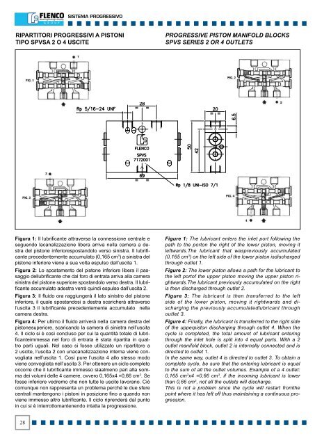
<strong>SISTEMA</strong> PROGRESSIVORIPARTITORI PROGRESSIVI A PISTONITIPO SPVSA 2 O 4 USCITEPROGRESSIVE PISTON MANIFOLD BLOCKSSPVS SERIES 2 OR 4 OUTLETSFigura 1: Il lubrificante attraversa la connessione centrale eseguendo lacanalizzazione libera arriva nella camera a destradel pistone inferiorespostandolo verso sinistra. Il lubrificanteprecedentemente accumulato (0,165 cm 3 ) a sinistra delpistone inferiore viene a sua volta espulso dall’uscita 1.Figura 2: Lo spostamento del pistone inferiore libera il passaggiodellubrificante che dal foro di entrata arriva alla camerasinistra del pistone superiore spostandolo verso destra. Il lubrificanteaccumulato adestra verrà quindi espulso dall’uscita 2.Figura 3: Il fluido ora raggiungerà il lato sinistro del pistoneinferiore, il quale spostandosi a destra scaricherà attraversol’uscita 3 il lubrificante precedentemente accumulato nellacamera destra.Figura 4: Per ultimo il fluido arriverà nella camera destra delpistonesuperiore, scaricando la camera di sinistra nell’uscita4. Il ciclo si è così concluso per cui la quantità totale di lubrificanteimmessanel foro di entrata è stata ripartita in quattroparti uguali. Nel caso si fosse utilizzato un ripartitore a2 uscite, l’uscita 2 con unacanalizzazione interna viene convogliatanell’uscita 1. Così pure l’uscita 4 allo stesso modoviene convogliata nell’uscita 3. Per ottenere un ciclo completooccorre che il lubrificante immesso siaalmeno pari alla sommadei volumi delle 4 camere, ovvero 0,165x4 =0,66 cm 3 . Sefosse inferiore vedremo che non tutte le uscite lavorano. Ciòcomunque non rappresenta un problema perché le due sferecentrali mantengono i pistoni in posizione fino a quando nonviene immesso altro lubrificante. Il ciclo riprenderà dal puntoin cui si è interrottomantenendo intatta la progressione.Figure 1: The lubricant enters the inlet port following thepath to the porton the right of the lower piston, moving itleftwards.The lubricant that waspreviously accumulated(0,165 cm 3 ) on the left side of the lower piston isdischargedthrough outlet 1.Figure 2: The lower piston allows a path for the lubricant tothe left portof the upper piston moving the upper piston rightwards.Thelubricant previously accumulated on the rightis then discharged through outlet 2.Figure 3: The lubricant is then transferred to the leftside of the lower piston, moving it rightwards and dischargingthe previously accumulatedlubricant throughoutlet 3.Figure 4: Finally, the lubricant is transferred to the right sideof the upperpiston discharging through outlet 4. When thecycle is completed, the total amount of lubricant enteringthrough the inlet hole is split into 4 equal parts. With a 2outlet manifold block, outlet 2 is internally connected and isdirected to outlet 1.In the same way, outlet 4 is directed to outlet 3. To obtain acomplete cycle, be sure that the entering lubricant is equalto the sum of all the outlet volumes. Example of a 4 outlet:0,165 cm 3 x4 =0,66 cm 3 , if the incoming lubricant is lowerthan 0,66 cm 3 , not all the outlets will discharge.This is not a problem since the cycle will restart fromthepoint where it has left off thus maintaining a continuous progression.28