
You also want an ePaper? Increase the reach of your titles
YUMPU automatically turns print PDFs into web optimized ePapers that Google loves.
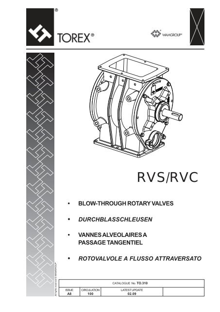
1TECHNICAL CATALOGUEAll rights reserved © WAMGROUPISSUEA8• BLOW-THROUGH ROTARY VALVESTECHNICAL CATALOGUE• DURCHBLASSCHLEUSENTECHNISCHER KATALOGUE<strong>RVS</strong>/<strong>RVC</strong>• VANNES ALVEOLAIRES A PASSAGE TANGENTIELCATALOGUE TECHNIQUE• ROTOVALVOLE A FLUSSO ATTRAVERSATOCATALOGO TECNICOCIRCULATION100CATALOGUE No. TO.310 T.LATEST UPDATE02.09
<strong>RVS</strong> • <strong>RVC</strong>- INTRODUCTION02.09- EINFÜHRUNG- INTRODUCTION- INTRODUZIONE TO.310.T. 011TYPE<strong>RVS</strong> - <strong>RVC</strong>MASCHINENTYP<strong>RVS</strong> - <strong>RVC</strong>TYPE<strong>RVS</strong> - <strong>RVC</strong>TIPO<strong>RVS</strong> - <strong>RVC</strong>DESCRIPTIONBlow-through rotary valvesBESCHREIBUNGDurchblasschleusenDÉSIGNATIONVannes alveolaires a passagetangentielDESCRIZIONERotovalvola a flusso attraversatoUSE<strong>RVS</strong> - <strong>RVC</strong> series of rotary valvesare conceived and designed foruse in pneumatic conveyor systems,in accordance with the qualitystandards required by the market.VERWENDUNGSZWECKDie Durchblasschleusen derBaureihe <strong>RVS</strong>-<strong>RVC</strong> wurden fürden Einsatz in pneumatischenFörderanlagen entwickelt undentsprechen in vollem Umfangdem marktüblichen Qualitätsstandard.EMPLOI PRÉCONISÉLes vannes rotatives modèle <strong>RVS</strong>- <strong>RVC</strong> sont indiquées pour êtreutilisées dans les installations àtransport pneumatique, dans lerespect des standards de qualitéexigés par le marché.FUNZIONE D’USOLe rotovalvole modello <strong>RVS</strong> - <strong>RVC</strong>sono indicate per alimentazionee scarico controllato di prodotti inpolvere o granulari da elementi diimmagazzinamento.IMPROPER USE<strong>RVS</strong> - <strong>RVC</strong> rotary valves are NOTdesigned to work in dangerousconditions or with dangerous materials.If the equipment has to operatein these conditions, theManufacturer must be informed.KONTRAINDIKATIONENDie Durchblasschleusen derModellreihe <strong>RVS</strong>-<strong>RVC</strong> sind wederfür gefährliche Anwendungennoch zum Handling von gefährlichenMedien geeignet. Sollteder Betreiber eine <strong>RVS</strong>-<strong>RVC</strong>-Schleuse für gefährliche Medienbzw. Anwendungen einsetzenwollen, so muß er zuvorden Hersteller um Erlaubnis fragen.CONTRE-INDICATIONSLes vannes rotatives standards dela classe <strong>RVS</strong> - <strong>RVC</strong> N’ONT PASété projetées pour travailler dansdes conditions ou avec des produitsdangereux; par conséquentsi la machine doitrat répondre àces exigences le constructeur doitobligatoirement en être informé.CONTROINDICAZIONILe rotovalvole modello <strong>RVS</strong> - <strong>RVC</strong>sono concepite e progettate perl’impiego in impianti a trasportopneumatico, nel rispetto deglistandard qualitativi richiesti dalmercato.Dangerous materials:• explosives• toxic• flammable• harmful and similarAls gefährliche Medien gelten:• explosive,• giftige,• feuergefährliche• in irgendeiner Weise schädlicheLes produits suivants sont considérésdangereux:• explosifs,• toxiques,• inflammables,• nocifs et/ou similiares.Si ritengono materiali pericolosi:• esplosivi,• tossici,• infiammabili,• nocivi e/o simili.Dangerous applications:• extracting the materials listedabove from silos or storage containers.Als gefährliche Anwendungen gelten:• der Austrag von den oben genanntenMedien aus Silos oderanderen Behältern.Les applications suivantes sontconsidérées dangereuses:• extraction des silos ou cellulescontenant les produits indiquésci-dessusSi ritengono applicazioni pericolose:• estrazioni da silo o celle contenentii suddetti materiali
-GENERAL DIAGRAM02.09<strong>RVS</strong> • <strong>RVC</strong>--GERÄTEAUFBAUSCHEMA GENERAL1-SCHEMA GENERALETO.310.T. 02TOREXTOREX9352293520ItemPos.Description - BezeichnungDésignation - DescrizioneQuantity - MengeQuantitè - Quantità1234567Casing - GehäuseCorps - CorpoRotor - ZellenradRotor - RotoreDrive plate - AntriebslagerschildCouvercle motorsation - Coperchio porta motorizzazioneMotor driven or bare shaft - AntriebswellenzapfenArbre type motorisé ou type nu - Albero tipo motorizzato o tipo nudoCover plate opposite drive end - Abtriebsseitiger LagerschildCouvercle opposé motorisation - Coperchio lato folleScraper set - AbstriefersetGroupe racleure - Gruppo raschiatoreConveying pipe connection - FörderleitungsanschlußConnexion tube de transport - Imbocco tubo di trasporto1111112
<strong>RVS</strong> • <strong>RVC</strong>- GENERAL DIAGRAM- GERÄTEAUFBAU- SCHEMA GENERALEXTERNAL BEARINGSEXTERNE LAGERPALIERS EXTERIEURS02.091- SCHEMA GENERALESUPPORTI ESTERNITO.310.T. 032 1 1ItemPos.Description - Beschreibung - Description - DescrizioneQ.ty1 External Bearings - Externe Lager - Paliers extérieurs - Supporti esterni 21Drive mount for external valve bearings - Antriebskonsole für externe SchleusenlagerSupport motoréducteur pour paliers extérieurs des distributeurs - Supporto motoriduttore per valvola supporti esterni1
<strong>RVS</strong> • <strong>RVC</strong>- TECHNICAL DATA- TECHNISCHE DATEN- DONNEES TECHNIQUES- DATI TECNICI02.091TO.310.T. 04Operating temperature - Betriebstemperatur - Température d'emploi - Temperature d'utilizzoComponentDirect DriveChain DriveExternal supportCarbon steel ConstructionStainless Steel ConstructionChromed coatingNickel coatingTefloan coatingStandard seal NBRHight Temperature <strong>Sea</strong>l VitonWORKING TEMPERATURE (°C)From -20 to +80 From +80 to +150 From +150 to +220Whit external support only- Dimensions, footprint and ratingare detailed in the next pages.- Noise level:
-TECHNICAL DATA02.09<strong>RVS</strong> • <strong>RVC</strong>--TECHNISCHE DATENDONNEES TECHNIQUES1-DATI TECNICITO.310.T. 05Losses due to pressure differential during operation - Verluste infolge Druckdifferenzen während des BetriebsPertes dûes au différentiel de pression durant l'exercice - Perdite dovute al differenziale di pressione in esercizio120100Nm3/h806040<strong>RVS</strong>/C 05<strong>RVS</strong>/C 10<strong>RVS</strong>/C 15<strong>RVS</strong>/C 20<strong>RVS</strong>/C 352000,2 1 0,4 2 0,6 3 0,8 4bar
-TECHNICAL DATA02.09<strong>RVS</strong> • <strong>RVC</strong>--TECHNISCHE DATENDONNEES TECHNIQUES1-DATI TECNICITO.310.T. 06- The loading ratio in case ofpowders or similar materialsvaries accordino to the flowabilityof the material and rotorrotation speed. Powder loadingcoefficient (at optimumspeed of 20 rpm) = 0.8.- Der Füllkoeffizient ändert sichbei staubförmigen oder ähnlichenGütern mit der Rieselfähigkeitdes Materials und derRotationsgeschwindigkeit desRotors. Bei staubförmigemSchüttgut und der optimalenDrehzahl von 20 min -1 beträgtder Füllgrad 80%.- Dans le cas des poudres ou desmatières similaires le coefficientde remplissage varie en fonctionde la fluidité du produit etde la vitesse de rotation du rotor.Coefficient de remplissagepour les poudres (à vitesse optimale20 TR/MIN) = 0.8.- Il coefficiente di riempimento nelcaso di polveri o materiali similivaria in funzione della scorrevolezzadel prodotto e della velocitàdi rotazione del rotore. Coefficientedi riempimento perpolveri (a velocità ottimale 20RPM): 0.8.r.p.m.min -1tpmgiri/minvery free flowing - gut rieselfähigtrès fluide - molto scorrevoleLoading coefficient - FüllkoeffizientCoefficient de remplissage - Coefficiente di riempimentoMaterial - Schüttgut - Matériau - Materialefree flowing - rieselfähigfluide - scorrevolepoorly flowing - schwach rieselfähigpeu fluide - poco scorrevole< 10 0.9 0.85 0.810 ÷ 20 0.8 0.75 0.7> 20 0.7 0.65 0.6- Available speeds 10/20/30RPM; speed variator 4-22 RPM.- Standard-Drehzahl für Antriebemit konstanter Drehzahl = 10/20/30 min-1; Standard-Regelbereichfür mechanische Regelantriebe= 4 bis 22 min -1 .- Vitesses de base disponibles10/20/30 TR/MIN; variateur avecplage de 4-22 TR/MIN.- Velocità di base disponibili 10/20/30 RPM; variatore con campo4-22 RPM.- Wear is reduced at lower operatingspeeds. It is best to uselarge cubic capacity at slowspeeds.- Je niedriger die Drehzahl, destogeringer ist der Verschleiß. Besondersbei abrasiven Mediensollten daher großvolumige undlangsam drehende Schleusenverwendet werden.- Limitation de l’usure aux vitessesles plus basses: l’utilisationde grandes cylindrées à bassevitesse est recommandée.- Limitazione dell’usura alle velocitàpiù basse: è consigliabileimpiegare grandi cilindrate abasse velocità.- Different fabrication materials forvarious products and applications.- Die Wahl des Werkstoffes istvom Produkt abhängig (siehenachfolgende allgemeine Richtlinienzur Wahl des geeignetenWerkstoffes).- Matériaux de construction enfonction des caractéristiquesdes produits.- Materiali costruttivi in funzionedelle caratteristiche dei prodotti.AMaterial for use with noncontaminatingproducts:Body:Cover:Rotor:grey cast ironcast ironsteelMedien ohne besondereEigenschaften:Gehäuse: GraugußEndschilde: GraugußZellenrad: StahlApplication diverses de matièresne pouvant pas être contaminées:Corps: Fonte griseCouvercles: Fonte griseRotor: AcierApplicazioni varie di materialinon contaminabili:Corpo: Ghisa grigiaCoperchi: Ghisa grigiaRotore: AcciaioAbrasive products:Abrasive Medien:Produits abrasifs:Prodotti abrasivi:BBody: chromium or nickel platedcast ironCovers: chromium or nickel platedcast ironRotor: steel with Vulkolan scrapersGehäuse: verchromter odervernickelter GraugußEndschilde: verchromter odervernickelter GraugußZellenrad: Stahl mit Schleißleistenaus VulkolanCorps: Fonte grise chromée ounickeléeCouvercles: Fonte grise chromée ouRotor:nickeléeAcier avec bavettes enVulkolanCorpo: Ghisa grigia cromata onichelataCoperchi: Ghisa grigia cromata onichelataRotore: Acciaio con bavette inVulkolanCorrosive products:Korrosive Medien:Produits corrosifs:Prodotti corrosivi:CBody: nickel plated cast ironCovers: nickel plated cast ironRotor: nickel plated cast ironGehäuse: vernickelter GraugußEndschilde: vernickelter GraugußZellenrad: vernickelter GraugußCorps: Fonte grise nickeléeCouvercles: Fonte grise nickeléeRotor: Fonte grise nickeléeCorpo: Ghisa grigia nichelataCoperchi: Ghisa grigia nichelataRotore: Ghisa grigia nichelata
<strong>RVS</strong> • <strong>RVC</strong>---FINISHINGFINISHFINITION02.091-FINITURATO.310.T. 07* **3 0 0 3 03Finishing Finish Finissage FinituraPaint Anstrich Peinture VerniciaturaINTERNAL - INNEN - INTERIEUR - INTERNOPaint Anstrich Peinture Verniciatura0none keiner aucune nessunaPaint colour Farbton Anstrich Tonalité Tonalità0none keiner aucune nessunaEXTERNAL - AUßEN - EXTERIEUR - ESTERNOPaint Anstrich Peinture Verniciatura31 primer+ 1x Grund+ 1 antirouille+ 1 mano1 paint coat 1x Deck 1 peinture + 1 manoPaint colour Farbton Anstrich Tonalité Tonalità1)2)O none Keiner aucune nessunaA yellow Caterpillar* Caterpillar gelb* jaune Caterpillar* giallo Caterpillar*B RAL 1013 pearl white Perlweiss blanc perle bianco perlaC RAL 1015 light ivory Hellelfenbein ivoire clair avorio chiaroD RAL 5010 gentian blue* Enzianblau* bleu gentiane* blu genziana*E RAL 5015 sky blue Himmelblau bleu ciel blu cieloF RAL 6011 reseda green Resedagrün vert réséda verde resedaG RAL 7035 light grey* Lichtgrau* gris lumière* grigio luce*H RAL 7032 pebble grey Kieselgrau gris gravier grigio ghiaiaI RAL 7001 silver grey Silbergrau gris argent grigio argentoL RAL 9001 cream white Cremeweiß blanc crème bianco cremaM RAL 9002 grey white Grauweiß blanc gris bianco grigioN RAL 9010 pure white Reinweiß blanc pur bianco puroP alluminium Aluminium Aluminium AlluminioX ecological colour Ökofarben Tonalité écologiques Tonalità ecologicheY non ecological colour Nicht-Ökofarben Tonalités non écologiques Tonalità non ecologicheZ to be specified Zu spezifizieren à préciser su specifica* Recommended colours* Empfohlene Farben* Tonalités conseillées* Tonalità consigliate1) See Table X page T.072) See Table Y page T.07Specify colours in tables X and Yin the order.1) Siehe Tabelle X, Seite T.072) Siehe Tabelle Y, Seite T.07Farbtöne für Tabellen X und Y inder Bestelung angeben.1) Voir tab. X, page T.072) Voir tab. Y, page T.07Spécifier Tonalités pour tab.X et Y dans la commande.1) Vedi Tab. X pag. T.072) Vedi Tab. Y pag. T.07Le tonalità delle tabelle X e Y devonoessere specificate nell’ordine.The antirust is a red-brown colour.Farbton Grundanstrich = rotbraun.Tonalité antirouille = rouge-marron.Tonalità antiruggine = rosso-marrone.
<strong>RVS</strong> • <strong>RVC</strong>- COLOURS- FARBTÖNE- TONALITES- TONALITÀ02.091TO.310.T. 08X- “ECOLOGICAL” RAL COLOURS THAT DO NOT CONTAIN LEAD OR CHROME- “ÖKOLOGISCHE” RAL-TÖNE OHNE BLEI- UND CHROMANTEILE- TONALITES RAL “ECOLOGIQUES” SANS CHROME ET PLOMB- TONALITÀ RAL “ECOLOGICHE” SENZA CROMO E PIOMBO1000 1001 1002 1011 1014 10193005 3007 3009 30274001 4004 4005 4006 4007 40085000 5001 5002 5003 5004 5005 5507 5008 5009 5011 5012 5013 5014 50176000 6003 6004 6006 6012 6013 6015 6016 6019 6020 6021 6022 6025 6026 6027 6028 6033 60347000 7002 7003 7004 7005 7006 7007 7008 7009 7010 7011 7012 7013 7015 7016 7021 7022 70237024 7025 7026 7030 7031 7033 7034 7036 7037 7038 7039 7040 7042 7043 70448000 8001 8002 8004 8011 8015 8016 8017 8019 8022 8024 8025 80289003 9004 9005 9011 9016 9017 9018Y- “NON ECOLOGICAL” RAL COLOURS CONTAINING LEAD OR CHROME- NICHT “ÖKOLOGISCHE” RAL-TÖNE MIT BLEI- UND CHROMANTEILEN- TONALITES RAL “NON ECOLOGIQUES” AVEC CHROME ET PLOMB- TONALITÀ RAL “NON ECOLOGICHE” CONTENENTI CROMO - PIOMBORAL 1006 Maize yellow Maisgelb Jaune mais Giallo maisRAL 1007 Chrome yellow Chromgelb Jaune chrome Giallo cromoRAL 1018 Zinc yellow Zinkgelb Jaune zinc Giallo zincoRAL 2008 Light red orange Hellrotorange Rouge orange clair Arancio rosso chiaroRAL 6017 May green Maigrün Vert mai Verde maggioRAL 6018 Yellow green Gelbgrün Vert jaune Verde giallo
<strong>RVS</strong> • <strong>RVC</strong>----ORDER CODES02.09BESTELLCODESCODES DE SELECTIONCODICI DI SCELTA TO.310.T. 091<strong>RVS</strong> 10 20 1 0 0 0 0ROTORBODY TREATMENTC = Teflon-coatedD = Nickel-platedH = AISI 304M= AISI 3160= StandardA = Chrome-platedB = Teflon-coatedC = Nickel-plated0= StandardSEALSA = High temperatureB = Purged sealsC = High temperature Purged seals0= StandardSTRIPSBODY MATERIAL1 = Cast iron2 = Stainless steel AISI 304A = VulkolanB = Viton ®D = Teflon5 = Teflon and Scraper4 = Viton ® and Scraper3 = Vulkolan and Scraper1 = Scraper0 = Without strips<strong>RVS</strong> - <strong>RVC</strong>DRIVE UNITTHROUGHPUT05 = 5 litres per revolution10 = 10 litres per revolution15 = 15 litres per revolution20 = 20 litres per revolution35 = 35 litres per revolutionAE = Bare shaft external bearingsAN = Bare shaftVU = 60Hz power supply motor mech. speed changerVM= Mechanical speed changerVS = Mechanical speed changer without motor10 = rpm20 = rpm30 = rpmSW = Provision for SEW drive unit (<strong>RVS</strong>/C35 only)SU = without motor with gear reducer for 60HzSP = Without motor with gear reducer 10 RPMSM = Without motor (gear reducer for 20/30 RPM)SR = Without gear reducerNC = NEMA std. gear reducer2U = 20 rpm for 60 Hz power supply3U = 30 rpm for 60 Hz power supply2U = 20 rpm for 60 Hz power supply1P = 10 rpm with primary brand motor2P = 20 rpm with primary brand motor3P = 30 rpm with primary brand motor1S = 10 rpm with fan-cooled motor2S = 20 rpm with fan-cooled motor3S = 30 rpm with fan cooled motor1T = 10 rpm with motor with Thermistors2T = 20 rpm with motor with Thermistors3T = 30 rpm with motor with Thermistors1C = Chain transmission 10 RPM2C = Chain transmission 20 RPM3C = Chain transmission 30 RPM1E = Chain transmission 10RPM external bearings2E = Chain transmission 20RPM external bearings3E = Chain transmission 30RPM external bearingsTS = Chain transmission without gear motor 20/30 RPMTO = Chain transmission without gear motor 10 RPM<strong>RVS</strong> =Blow-through rotary valve<strong>RVC</strong> =Drop-through rotary valve
-ORDER CODES02.09<strong>RVS</strong> • <strong>RVC</strong>--BESTELLCODESCODES DE SELECTION1-CODICI DI SCELTATO.310.T. 10<strong>RVS</strong> 10 20 1 0 0 0 0ROTORGEHÄUSEBEHANDLUNGC = Teflon-beschichtetD = VernickeltH = Edelstahl 1.4301M= Edelstahl 1.44010= StandardA = VerchromtB = Teflon-beschichtetC = Vernickelt0= StandardDICHTUNGENA = HitzebeständigB = SperrluftdichtungenC = Sperrluftdichtungen hitzebeständig0= StandardSCHLEISSLEISTENGEHÄUSEWERKSTOFF1 = Gusseisen2 = Edelstahl 1.4301A = VulkollanB = Viton ®D = Teflon5 = Teflon und Abstreifer4 = Viton ® und Abstreifer3 = Vulkollan und Abstreifer1 = Abstreifer0 = Ohne Schleißleisten<strong>RVS</strong> - <strong>RVC</strong>ANTRIEBFÖRDERLEISTUNG05 = 5 Liter pro Umdrehung10 = 10 Liter pro Umdrehung15 = 15 Liter pro Umdrehung20 = 20 Liter pro Umdrehung35 = 35 Liter pro UmdrehungAE = Freier Wellenzapfen externe TrägerAN = Freier WellenzapfenVU = Mechanisches Regelgetriebe Motor Speisung 60HzVM= Mechanisches DrehzahlreglerVS = Mechanischer Drehzahlregler ohne Motor10 = Umdrehungen pro Minute20 = Umdrehungen pro Minute30 = Umdrehungen pro MinuteSW = Vorrüstung für Antrieb SEW (nur <strong>RVS</strong>/C35)SU = ohne Motor mit Untersetzungsgetriebe für 60 HzSP = Ohne Motor mit Untersetzungsgetriebe 10 U/minSM = Ohne Motor (Untersetzungsgetriebe für 20/30 U/min)SR = Ohne UntersetzungsgetriebeNC = Untersetzungsgetriebe NEMA2U = 20 Umdrehungen pro Minute für Speisung 60 Hz3U = 30 Umdrehungen pro Minute für Speisung 60 Hz2U = 20 Umdrehungen pro Minute für Speisung 60 Hz1P = 10 Umdrehungen pro Minute mit Motor bester Marke2P = 20 Umdrehungen pro Minute mit Motor bester Marke3P = 30 Umdrehungen pro Minute mit Motor bester Marke1S = 10 Umdrehungen pro Minute mit servobelüftetem Motor2S = 20 Umdrehungen pro Minute mit servobelüftetem Motor3S = 30 Umdrehungen pro Minute mit servobelüftetem Motor1T = 10 Umdrehungen pro Minute mit Motor mit Thermistoren2T = 20 Umdrehungen pro Minute mit Motor mit Thermistoren3T = 30 Umdrehungen pro Minute mit Motor mit Thermistoren1C = Kettentrieb 10 U/min2C = Kettentrieb 20 U/min3C = Kettentrieb 30 U/min1E = Kettentrieb 10 U/min externe Träger2E = Kettentrieb 20 U/min externe Träger3E = Kettentrieb 30 U/min externe TrägerTS = Kettentrieb ohne Getriebemotor 20/30 U/minTO = Kettentrieb ohne Getriebemotor 10 U/min<strong>RVS</strong> =Durchblasschleusen<strong>RVC</strong> =Freifallschleusen
<strong>RVS</strong> • <strong>RVC</strong>- ORDER CODES02.09- BESTELLCODES- CODES DE SELECTION- CODICI DI SCELTATO.310.T. 111<strong>RVS</strong> 10 20 1 0 0 0 0ROTORC = TéflonéD = NickeléH = Aisi 304M= Aisi 3160= StandardTRAITEMENT DU CORPSA = ChroméB = TéflonéC = Nickelé0= StandardJOINTSA = Haute températureB = Etanchéités fluxéesC = Etanchéités fluxées Haute température0= StandardBAVETTESMATÉRIAU CORPS1 = Fonte2 = Inox AISI 304A = VulkolanB = Viton ®D = Teflon5 = Teflon et Racleur4 = Viton ® et Racleur3 = Vulkolan et Racleur1 = Racleur0 = Sans bavettesDÉBIT<strong>RVS</strong> • <strong>RVC</strong>MOTORISATION05 = 5 litres par tour10 = 10 litres par tour15 = 15 litres par tour20 = 20 litres par tour35 = 35 litres par tourAE = Arbre nu paliers extérieursAN = Arbre nuVU =Variateur mécanique moteur aliment. 60HzVM= Variateur mécaniqueVS = Variateur mécanique sans moteur10 = tours par minute20 = tours par minute30 = tours par minuteSW = Prévu pour motorisation SEW (<strong>RVS</strong>/C35 seulement)SU = sans moteur avec réducteur pour 60HzSP = Sans moteur avec réducteur 10 tr/mnSM = Sans moteur (réducteur 20/30 tr/mn)SR = Sans RéducteurNC = réducteur norme NEMA2U = 20 tours par minute pour alimentation 60 Hz3U = 30 tours par minute pour alimentation 60 Hz2U = 20 tours par minute pour alimentation 60 Hz1P = 10 tours par minute avec moteur de marque2P = 20 tours par minute avec moteur de marque3P = 30 tours par minute avec moteur de marque1S = 10 tours par minute avec moteur servo-ventilé2S = 20 tours par minute avec moteur servo-ventilé3S = 30 tours par minute avec moteur servo-ventilé1T = 10 tours par minute avec moteur à Thermistances2T = 20 tours par minute avec moteur à Thermistances3T = 30 tours par minute avec moteur à Thermistances1C = Transmission par chaîne 10 tr/mn2C = Transmission par chaîne 20 tr/mn3C = Transmission par chaîne 30 tr/mn1E = Transmission par chaîne 10 tr/mn supports extérieurs2E = Transmission par chaîne 20 tr/mn supports extérieurs3E = Transmission par chaîne 30 tr/mn supports extérieursTS = Transmission à chaîne sans motoréducteur 20/30 tr/mnTO = Transmission à chaîne sans motoréducteur 10 tr/mn<strong>RVS</strong> =Distributeur alvéolaire à flux traversé<strong>RVC</strong> =Distributeur alvéolaire à gravité
<strong>RVS</strong> • <strong>RVC</strong>- ORDER CODES- BESTELLCODES- CODES DE SELECTION- CODICI DI SCELTA02.091TO.310.T. 12<strong>RVS</strong> 10 20 1 0 0 0 0ROTOREC = TeflonatoD = NichelatoH = Aisi 304M= Aisi 3160= StandardTRATTAMENTO CORPOA = CromatoB = TeflonatoC = Nichelato0= StandardTENUTEA = Alta temperaturaB = Tenute flussateC = Tenute flussate Alta temperatura0= StandardBAVETTEMATERIALE CORPO1 = Ghisa2 = Inox AISI 304A = VulkolanB = Viton ®D = Teflon5 = Teflon e Raschiatore4 = Viton ® e Raschiatore3 = Vulkolan e Raschiatore1 = Raschiatore0 = Senza bavette<strong>RVS</strong> - <strong>RVC</strong>PORTATAMOTORIZZAZIONE05 = 5 litri per giro10 = 10 litri per giro15 = 15 litri per giro20 = 20 litri per giro35 = 35 litri per giroAE = Albero nudo supporti esterniAN = Albero nudoVU = Variatore meccanico motore alimentaz. 60HzVM= Variatore meccanicoVS = Variatore meccanico senza motore10 = giri al minuto20 = giri al minuto30 = giri al minutoSW = Predisposta per motorizzazione SEW (solo <strong>RVS</strong>/C35)SU = senza motore con riduttore per 60HzSP = Senza motore con riduttore 10 RPMSM = Senza motore (riduttore per 20/30 RPM)SR = Senza riduttoreNC = riduttore norme NEMA2U = 20 giri al minuto per alimentazione 60 Hz3U = 30 giri al minuto per alimentazione 60 Hz2U = 20 giri al minuto per alimentazione 60 Hz1P = 10 giri al minuto con motore marca primaria2P = 20 giri al minuto con motore marca primaria3P = 30 giri al minuto con motore marca primaria1S = 10 giri al minuto con motore servoventilato2S = 20 giri al minuto con motore servoventilato3S = 30 giri al minuto con motore servoventilato1T = 10 giri al minuto con motore con Termistori2T = 20 giri al minuto con motore con Termistori3T = 30 giri al minuto con motore con Termistori1C = Trasmissione a catena 10RPM2C = Trasmissione a catena 20RPM3C = Trasmissione a catena 30RPM1E = Trasmissione a catena 10RPM supporti esterni2E = Trasmissione a catena 20RPM supporti esterni3E = Trasmissione a catena 30RPM supporti esterniTS = Trasmissione a catena senza motoriduttore 20/30 RPMTO = Trasmissione a catena senza motoriduttore 10 RPM<strong>RVS</strong> =Rotovalvola a flusso attraversato<strong>RVC</strong> =Rotovalvola a caduta
<strong>RVS</strong> • <strong>RVC</strong>- TOP AND BOTTOM FLANGE- OBERER UND UNTERER FLANSCH- BRIDE SUPERIEURE ET INFERIEURE- FLANGIATURE SUPERIORE E INFERIORE02.091TO.310.T. 13Type A1 A2 B1 B2 C1 C2 D1 D2 E1 E2 E3E3n°F1 F2 F3F3N°G1G1N°G2 N°<strong>RVS</strong>/C 05 170 122 234 184 166 121 234 184 164 210 105 2 164 210 105 2 M8 6 9 6<strong>RVS</strong>/C 10 238 135 298 200 235 135 298 200 172 270 135 2 172 270 135 2 M 8 6 10 6<strong>RVS</strong>/C 15 276 148 342 222 276 158 342 222 194 310 155 2 194 310 155 2 M 10 6 12 6<strong>RVS</strong>/C 20 337 196 428 278 337 200 428 278 250 390 195 2 250 390 195 2 M 12 6 13 6<strong>RVS</strong>/C 35 470 240 585 352 480 220 585 332 300 540 180 3 300 540 180 3 M 12 8 14 8
<strong>RVS</strong> • <strong>RVC</strong>- PIPE CONNECTION- ROHRLEITUNGSVERBINDUNG- RACCORDEMENT TUBE- IMBOCCHI02.091TO.310.T. 14<strong>RVS</strong> 35 <strong>RVS</strong> 152 x Ø14162 x Ø10103024Ø140.5Ø118Ø1271852201530Ø74Ø811161361020<strong>RVS</strong> 20<strong>RVS</strong> 102 x Ø13 152 x Ø9 928Ø115Ø96Ø1031451731430<strong>RVS</strong> 052xØ918Ø7020Ø64 9Ø711895108Ø54Ø61Ø92Ø108168Only for <strong>RVS</strong> - Nur für <strong>RVS</strong> - Seulement pour <strong>RVS</strong> - Solo per <strong>RVS</strong>
<strong>RVS</strong> • <strong>RVC</strong>- SIMPLE STEM VALVES02.09- ZELLENDRADSCHLEUSEN MIT FREIEM WELLENZAPFEN- VANNES A ARBRE NU- VALVOLE AD ALBERO NUDO TO.310.T. 151Configurazione - Configurazione - Configurazione - Configurazione<strong>RVC</strong>DTOREXE FHCØIAMBLØPGTOREXONTabella dimensionale - Tabella dimensionale - Tabella dimensionale - Tabella dimensionale<strong>RVS</strong>/C ANType A B C Ø D E F G HØ Ionly - nurseulement - solo<strong>RVS</strong>L M N O Ø P<strong>RVS</strong>/C 05 165 244 134 260 55 130 10 335 54 285 409 80 8x7x32 ISO773 28 h7<strong>RVS</strong>/C 10 200 256 146 280 54 129 12 339 64 308 456 58 8x7x32 ISO773 28 h7<strong>RVS</strong>/C 15 214 288 165 323 69 153 12 399 74 347 502 50 10x8x40 ISO773 32 h7<strong>RVS</strong>/C 20 259 326 198 362 88 160 12 447 96 388 585 50 10x8x40 ISO773 32 h7<strong>RVS</strong>/C 35 330 425 221 430 105 185 17 530 118 460 755 95 12x8x70 ISO773 40 h7
-VALVES WITH GEAR MOTOR02.09<strong>RVS</strong> • <strong>RVC</strong>--ZELLENDRADSCHLEUSEN MIT ANTRIEBVANNES MOTORISÉES1-VALVOLE MOTORIZZATETO.310.T. 16r.p.m.min -1tpmgiri/min302010TypeDimensions - Abmessungen - Dimensions - DimensioniMotor - MotorMoteur - MotoreQ1 Q2 Q3 R1 R2 R3 H kW Giri<strong>RVS</strong>/C 05 505 342 163 550 130 420 335 0.55 1400<strong>RVS</strong>/C 10 572 372 200 560 140 420 339 0.75 1400<strong>RVS</strong>/C 15 605 390 215 588 162 426 399 1.1 1400<strong>RVS</strong>/C 20 705 444 261 608 181 426 447 1.5 1400<strong>RVS</strong>/C 35 890 558 332 740 217 523 530 2.2 1400<strong>RVS</strong>/C 05 505 342 163 550 130 420 335 0,55 900<strong>RVS</strong>/C 10 572 372 200 560 140 420 339 0.55 900<strong>RVS</strong>/C 15 605 390 215 588 162 426 399 0.75 900<strong>RVS</strong>/C 20 705 444 261 608 181 426 447 1.1 900<strong>RVS</strong>/C 35 890 558 332 740 217 523 530 1.5 900<strong>RVS</strong>/C 05 475 342 163 517 130 387 335 0,37 1400<strong>RVS</strong>/C 10 542 342 200 527 140 387 339 *0.37 1400<strong>RVS</strong>/C 15 585 370 215 572 162 410 399 0.55 1400<strong>RVS</strong>/C 20 658 397 261 591 181 410 447 *0.75 1400<strong>RVS</strong>/C 35 890 558 332 740 217 523 530 *1.1 900PretorqueVorgelegePrécouplePrecoppiayes - jaoui - siyes - jaoui - siyes - jaoui - sino - neinno - no* The dimensions given refer to valves with standard drive.* Werte beziehen sich auf Standardantriebe.* Mesures se rapportant à la vanne avec motorisation standard.* Quote riferite alla valvola con motorizzazione standard.
<strong>RVS</strong> • <strong>RVC</strong>---VALVES WITH VARIABLE SPEED MOTORZELLENDRADSCHLEUSEN MIT MECHANISCHEM REGELANTRIEBVANNES AVEC MOTOVARIATEUR MECANIQUE02.091-VALVOLE MOTORIZZATE CON MOTOVARIATORE DI GIRITO.310.T. 17TypeDimensions - AbmessungenDimensions - DimensioniQ1 Q2 Q3 R1 R2 R3 H kWMotor - MotorMoteur - Motorerpm - min -1tpm - giriVariator - RegelgetriebeVariateur - Variatorerpm - min -1tpm - giriRotor - RotorRotor - Rotorerpm - min -1tpm - giri<strong>RVS</strong>/C 05 407 244 163 605 130 475 335 0.37 1400 190-1000 4 - 20<strong>RVS</strong>/C 10 474 380 200 615 140 475 339 0.37 1400 190 - 1000 4 - 20<strong>RVS</strong>/C 15 639 424 215 724 162 562 399 0.75 1400 190 - 1000 4 - 20<strong>RVS</strong>/C 20 788 527 261 743 181 562 447 0.75 1400 190 - 1000 4 - 20<strong>RVS</strong>/C 35 930 596 332 870 217 653 530 1.5 1400 190 - 1000 4 - 20
-DIMENSIONS02.09<strong>RVS</strong> • <strong>RVC</strong>--PLATZBEDARFENCOMBREMENTS1-INGOMBRITO.310.T. 180510152035<strong>RVS</strong>/C A B C D EPower - LeistungPuissance - Potenza(kW)Torque - DrehmomentCouple - Coppia(Nm)10rpm 630345 0.37 30020rpm 630 525 492 380 345 0.55 23230rpm 630 345 0.55 14910 rpm 630310 0.37 30020 rpm 630 545 492 390 310 0.55 23230 rpm 630 310 0.55 14910 rpm 700360 0.55 47220 rpm 650 627 620 430 310 0.75 32830 rpm 650 310 1.1 30810 rpm 700340 0.55 47220 rpm 650 672 620 460 290 1.1 32830 rpm 650 290 1.1 30810 rpm 700240 1.1 92920 rpm 750 796 810 580 190 1.5 63330 rpm 750 190 2.2 630
<strong>RVS</strong> • <strong>RVC</strong>- DIMENSIONS- PLATZBEDARF- ENCOMBREMENTSEXTERNAL BEARINGS ANEXTERNE LAGER ANPALIERS EXTERIEURS AN02.091- INGOMBRISUPPORTI ESTERNI ANTO.310.T. 19BMAØPONTabella dimensionale - Tabella dimensionale - Tabella dimensionale - Tabella dimensionale<strong>RVS</strong>/C S.E ANType A B C N O Ø P<strong>RVS</strong>/C 05 239 289 528 50 8x7x32 ISO773 28 h7<strong>RVS</strong>/C 10 274 324 598 50 8x7x32 ISO773 28 h7<strong>RVS</strong>/C 15 308 379 687 45 10x8x40 ISO773 32 h7<strong>RVS</strong>/C 20 353 422 775 55 10x8x40 ISO773 32 h7<strong>RVS</strong>/C 35 416 495 911 75 12x8x70 ISO773 40 h7
-DIMENSIONSEXTERNAL BEARINGS02.09<strong>RVS</strong> • <strong>RVC</strong>--PLATZBEDARFENCOMBREMENTSEXTERNE LAGERPALIERS EXTERIEURS1-INGOMBRISUPPORTI ESTERNITO.310.T. 20AEBDC<strong>RVS</strong>/C A E D C BPower - LeistungPuissance - Potenza[ kW]051015203510rpm364518 0.3720rpm 589 26049238430rpm538 0.5510rpm376538 0.3720rpm 659 25549230rpm396 558 0.5510rpm2600.5520rpm 731425 620 6070.7521330rpm 1.110rpm2180.5520rpm 820 195 450 620 6471.130rpm 17010rpm126 511750 1.120rpm 9668101.530rpm167 536 7752.2
<strong>RVS</strong> • <strong>RVC</strong>---AIR OUTLETLUFTAUSLASSSORTIE D’AIR02.091-SCARICHI D’ARIATO.310.T. 21Type A B C D<strong>RVS</strong>/C 05 136 62 213 3/4" GAS<strong>RVS</strong>/C 10 145 63 213 3/4" GAS<strong>RVS</strong>/C 15 166 72 253 3/4" GAS<strong>RVS</strong>/C 20 181 100 279 3/4" GAS<strong>RVS</strong>/C 35 217 160 332 3/4" GAS
-DRIVE UNIT DATA02.09<strong>RVS</strong> • <strong>RVC</strong>--ANTRIEBSDATENCARACTÉRISTIQUES MOTORISATION1-DATI MOTORIZZAZIONETO.310.T. 22Locked rotor torque/ Locked rotor current/TypePowerSpeed Current Voltage EfficiencyRated TorquePower factorrated torquerated courrentLeistung No of Drehzahl Strom Spannung WirksamkeitNenndrehmomentSizeLeistungsf.Drehmoment blockiert Rotor/ Strom blockierter Rotor/Puissance poles Vitesse Courant Tension EfficacitéCouple nominalBaugrößeFacteur deNenndrehmomenNenndrehmomenPotenza N.pole Velocità Corrente Voltaggio EfficienzaCoppia nominaleTaillepuissanceCouple rotor bloqué/ Courant rotor bloqué/N.pôlesTagliaFattore diCouple nominalCouple nominalN.poli(kW) (tr/min) (A) (V) (%) potenza (Nm) Coppia rotore bloccato/ Corrente a rotore bloccato/coppia nominalecoppia nominale10 rpm 71 0.37 4 1400 1,1 380 67.0 0.75 2.52 2.1 5,220 rpm 80 0.5 6 930 1,8 380 65.0 0.72 5.13 1.9 4.730 rpm 80 0.5 4 1410 1.6 380 71.0 0.75 3.39 2.4 5.2<strong>RVS</strong>/C05VM 71 0.37 4 1400 1.1 380 67.0 0.75 2.52 1.9 5.2TC10 rpm71 0.37 4 1400 1.1 380 67.0 0.75 2.52 1.9 5.2TC20 rpm80 0.55 6 900 1.8 380 65.0 0.72 5.84 1.9 4.7TC30 rpm80 0.55 4 1400 1.6 380 71.0 0.75 3.75 2.4 5.210 rpm 71 0.37 4 1400 1,1 380 67.0 0.75 2.52 2.1 5,220 rpm 80 0.5 6 930 1,8 380 65.0 0.72 5.13 1.9 4.730 rpm 80 0.75 4 1410 2.0 380 73.0 0.70 5.08 2.4 6.0<strong>RVS</strong>/C10VM 71 0.37 4 1400 1.1 380 67.0 0.75 2.52 1.9 5.2TC10 rpm71 0.37 4 1400 1.1 380 67.0 0.75 2.52 1.9 5.2TC20 rpm80 0.55 6 900 1.8 380 65.0 0.72 5.84 1.9 4.7TC30 rpm80 0.55 4 1400 1.6 380 71.0 0.75 3.75 2.4 5.210 rpm 80 0.55 4 1400 1.6 380 71.0 0.75 3.75 2.4 5.220 rpm 90 0.75 6 940 2.3 380 69.0 0.72 7.62 2.0 5.530 rpm 90 1.1 4 1410 2.9 380 75.0 0.77 7.45 2.3 6.0<strong>RVS</strong>/C15VM 80 0.75 4 1410 2.0 380 73.0 0.77 5.08 2.4 6.0TC10 rpm80 0.55 4 1400 1.6 380 71.0 0.75 3.75 2.4 5.2TC20 rpm90 0.75 6 940 2.3 380 69.0 0.72 7.62 2.0 5.5TC30 rpm90 1.1 4 1410 2.9 380 75.0 0.77 7.45 2.3 6.010 rpm 80 0.75 4 1410 2.0 380 73.0 0.77 5.08 2.4 6.020 rpm 80 1.1 6 900 3.2 380 72.0 0.77 11.67 2.0 5.5430 rpm 90 1.5 4 1410 3.7 380 78.0 0.79 10.16 2.3 6.0<strong>RVS</strong>/C20VM 80 0.75 4 1410 2.0 380 73.0 0.77 5.08 2.4 6.0TC10 rpm80 0.5 4 1410 1.6 380 71.0 0.75 3.39 2.4 5.2TC20 rpm90 1.1 6 900 3.2 380 72.0 0.73 11.67 2.0 5.5TC30 rpm90 1.1 4 1410 2.9 380 75.0 0.77 7.45 2.3 6.010 rpm - 1.1 4 1410 3.9 380 75.0 0.75 7.5 2.3 6.020 rpm - 1.5 6 900 3.9 380 76.0 0.76 15.92 2.0 5.530 rpm - 2.2 4 1410 5.2 380 80.0 0.81 14.90 2.3 7.0<strong>RVS</strong>/C35VM - 1.5 4 1410 3.7 380 78.0 0.79 10.16 2.3 6.0TC10 rpm90 1.1 4 1410 2.9 380 75.0 0.77 7.45 2.3 6.0TC20 rpm100 1.5 6 900 3.9 380 76.0 0.76 15.92 2.0 5.5TC100 2.2 4 1410 5.2 380 80.0 0.81 14.90 2.3 7.030 rpm
<strong>RVS</strong> • <strong>RVC</strong>- ACCESSORIES- ZUBEHÖR- ACCESSOIRES- ACCESSORI02.091TO.310.T. 23ROTATION INDICATOR - ROTATIONSANZEIGER - INDICATEUR DE ROTATION- INDICATORE DI ROTAZIONEIf it is found to be necessary tocheck the rotary valve rotation,a rotation indicator kit with acapacitive sensor is available.The model without capacitivesensor (mounting) is also available.Sollte es erforderlich sein, dieRotation der Zellenradschleusezu überwachen, steht ein Bausatzmit Rotationsanzeiger zurVerfügung, der auf einem Kapazitätssensorbasiert.Es steht auch eine Version ohneKapazitätssensor (Vorrüstung)zur Verfügung:S’il s’avère nécessaire de contrôlerla rotation de la vanne rotativeun kit indicateur de rotationest disponible, avec capteurcapacitif.Il est aussi disponible dans laversion sans capteur capacitif(pré-équipement):Qualora fosse necessario controllarela rotazione della rotovalvola,è disponibile un kit indicatoredi rotazione basato su unsensore capacitivo.E’ disponibile anche la versionesenza sensore capacitivo (predisposizione):ItemPos.Code Description Benennung Description Descrizione13R00001A Complete kit Kompletter Bausatz Kit complet Kit completo13R00011A Mounting kit Vorrüstungs-Bausatz Kit pré-équipement Kit predisposizione1 3804CA0400 Cap Stopfen Bouchon Tappo2 20695421A Blade Flügel Pale Paletta3 20695401A Support Träger Support Supporto4 2902025200 M6x20 Hex soc. screw Inbusschraube M6x20 Vis Chc M6x20 Vite TCEI M6x205 3860IF0050 Capacitive sensor Kapazitätssensor Capteur capacitif Sensore capacitivoSee tab. Spare partsSiehe Ersatzteil-Tabelle6Voir tab. Pièces détachéesVedi tab. Ricambi7 2916020021Ring nut opp. drive end Ringmutter lose Seite Bague Côté Fou Ghiera Lato FolleThreaded rod M.10L= 80 mmGewindestange M.10L= 80 mmBarre Filetée M.10L= 80 mmBarra Filettata M.10L= 80 mm
<strong>RVS</strong> • <strong>RVC</strong>- ACCESSORIES- ZUBEHÖR- ACCESSOIRES- ACCESSORI02.091TO.310.T. 24PURGED SEALS - FLÜSSIGKEITSDICHTUNGEN - ETANCHEITÉS FLUXÉES - TENUTE FLUSSATEThe rotary valves with purgedseals contain the product insidethe valve by means of a counter-pressure.The seals ARE NOT greased!!Blow with continuous flowat 0.3 - 0.4 barDie Zellenradschleusen mit Flüssigkeitsdichtungerreichen dieAbdichtung des Dosierguts innerhalbder Schleuse mittels einesGegendrucks.Die Dichtungen werdenNICHT geschmiert!!Mit einem ständigen Luftflussvon 0,3 bis 0,4 bar versorgen.Les vannes rotatives à étanchéitésfluxées contiennent le produità l’intérieur de la vanne aumoyen d’une contre-pression.Les joints d’étanchéités NEdoivent pas être graissés !!Insuffler avec un débit continuà 0,3 - 0,4 barsLe rotovalvole con tenute flussaterealizzano il contenimentodel prodotto all’interno della valvolamediante una contropressione.Le tenute NON vengono ingrassate!!Insufflare con flusso continuoa 0.3 - 0.4 barØ 8mm air pipe connectionLuftschlauchanschluss Ø 8mmRaccord air tube Ø 8mmInnesto aria tubo Ø 8mm
<strong>RVS</strong> • <strong>RVC</strong>- ACCESSORIES- ZUBEHÖR- ACCESSOIRES- ACCESSORI02.091TO.310.T. 25SCRAPER - ABSTREIFEER - RACLEUR - RASCHIATOREIt is a scraper which cleans thetips of the blades after the rotorpocket is filled and before it entersthe inside the body. It thusprevents blocking of the rotorwhen used with granular products.Es handelt sich um eine Abstreifleiste,die die Enden der Flügelreinigt, nachdem die Rotortaschegefüllt worden ist und bevorsie in das Gehäuseinneregelangt. Er verhindert ein Blockierendes Rotors bei Verwendunggrobkörniger Produkte.Il s’agit d’une bavette racleusequi nettoie les extrémités despales une fois que la poche durotor a été remplie et avant qu’ellen’entre à l’intérieur du corps.Elle évite le blocage du rotor lorsde l’emploi de produits granulaires.E’ una bavetta raschiatrice chepulisce le estremità delle paledopo che la tasca del rotore èstata riempita e prima che entriall’interno del corpo. Evita quindiil bloccaggio del rotore quandousata con prodotti granulari.ItemPos.COMPONENTS - BESTANDTEILE - COMPOSANTS - COMPONENTICode Description Benennung Description Descrizione20938391A RV_05 Scraper body Abstreiferkörper RV_05 Corps racleur RV_05 Corpo raschiatore RV_0520938401A RV_10 Scraper body Abstreiferkörper RV_10 Corps racleur RV_10 Corpo raschiatore RV_10120938411A RV_15 Scraper body Abstreiferkörper RV_15 Corps racleur RV_15 Corpo raschiatore RV_1520938421A RV_20 Scraper body Abstreiferkörper RV_20 Corps racleur RV_20 Corpo raschiatore RV_2020938431A RV_35 Scraper body Abstreiferkörper RV_35 Corps racleur RV_35 Corpo raschiatore RV_3520938591A RV_05 Vulkollan tip Vulkolanleiste RV_05 Bavette vulkolan RV_05 Bavetta vulkolan RV_0520938601A RV_10 Vulkollan tip Vulkolanleiste RV_10 Bavette vulkolan RV_10 Bavetta vulkolan RV_10220938611A RV_15 Vulkollan tip Vulkolanleiste RV_15 Bavette vulkolan RV_15 Bavetta vulkolan RV_1520938621A RV_20 Vulkollan tip Vulkolanleiste RV_20 Bavette vulkolan RV_20 Bavetta vulkolan RV_2020938631A RV_35 Vulkollan tip Vulkolanleiste RV_35 Bavette vulkolan RV_35 Bavetta vulkolan RV_3520937791A RV_05 tip presser Leistenandrücker RV_05 Appuie-bavette RV_05 Premibavetta RV_0520937801A RV_10 tip presser Leistenandrücker RV_10 Appuie-bavette RV_10 Premibavetta RV_10320937811A RV_15 tip presser Leistenandrücker RV_15 Appuie-bavette RV_15 Premibavetta RV_1520937821A RV_20 tip presser Leistenandrücker RV_20 Appuie-bavette RV_20 Premibavetta RV_2020937831A RV_35 tip presser Leistenandrücker RV_35 Appuie-bavette RV_35 Premibavetta RV_354 2902120301 M6x10 hex. soc. screw Schraube TPSEI M6x10 Vis Fhc M6x10 Vite TPSEI M6x10ItemPos.Code kitCode Description Benennung Description Descrizione13002501A RV_05 Scraper kit Abstreifer-Bausatz RV_05 Kit racleur RV_05 Kit raschiatore RV_0513002511A RV_10 Scraper kit Abstreifer-Bausatz RV_10 Kit racleur RV_10 Kit raschiatore RV_10113002521A RV_15 Scraper kit Abstreifer-Bausatz RV_15 Kit racleur RV_15 Kit raschiatore RV_1513002531A RV_20 Scraper kit Abstreifer-Bausatz RV_20 Kit racleur RV_20 Kit raschiatore RV_2013002541A RV_35 Scraper kit Abstreifer-Bausatz RV_35 Kit racleur RV_35 Kit raschiatore RV_35
-ACCESSORIES02.09<strong>RVS</strong> • <strong>RVC</strong>--ZUBEHÖRACCESSOIRES1-ACCESSORITO.310.T. 26SURFACE TREATMENTS - OBERFLÄCHENBEHANDLUNG - TRAITEMENTS SUPERFICIELS - TRATTAMENTI SUPERFICIALITEFLON-COATED ROTARY VALVEZELLENRADSCHLEUSE MIT TEFLON-BESCHICHTUNGDISTRIBUTEUR ALVEOLAIRE TEFLONÉROTOVALVOLA TEFLONATANICKEL-PLATED ROTARY VALVEZELLENRADSCHLEUSE, VERNICKELTDISTRIBUTEUR ALVEOLAIRE NICKELÉROTOVALVOLA NICHELATAAISI304 / AISI 316 STAINLESS STEEL ROTARY VALVEZELLENRADSCHLEUSE, EDELSTAHL 1.4301/1.4401DISTRIBUTEUR ALVEOLAIRE ACIER INOX / AISI 316ROTOVALVOLA INOX AISI304 / AISI 316BODY AND COVERS CHROME-PLATED INSIDEGEHÄUSE UND DECKEL, INNEN VERCHROMTCORPS ET COUVERCLES CHROMÉS INTÉRIEUREMENTCORPO E COPERCHI CROMATI INTERNAMENTE
<strong>RVS</strong> • <strong>RVC</strong>- ORDER FORM02.09- BESTELLFORMULAR- FORMULAIRE DE COMMANDE- MODULO D’ORDINE TO.310.T. 271Order FormCOMPANYORDERMACHINE CODEDATEType of materialProduct…………… Flow rate……………. Specific weight………………….Humidity…………..Material temperature………………….Material particle size……………….Material featuresFlowable Adhesive HygroscopicAbrasive Explosive InflammablePlace of useInternalExternalGravity Pneumatic conveying Pneumatic conveying pressure…………..…barFeed systemFilter Silo HopperFilter pressure………………bar Other……………………………………..Drive Unit Technical FeaturesMotor-operated version Voltage...................Volts Frequency……………Hz. Direct transmissionChain transmissionRotation speed: 10 rpm 20 rpm 30 rpmMech. speed changer Thermistors Servo-ventilatedWithout Motor w/o gear reducer ABB/SIEMENS MotorNEMA std Gear reducerNEMA std MotorBare shaft<strong>Sea</strong>ls Technical FeaturesStandard High Temperature Air-purgedAir-purged seals for High TemperatureTechnical features of RotorRotor with Vulkollan flapsRotor with Viton flaps for high temperatureRotor with Teflon flapsRotor without flapsRotor material: Carbon steel AISI 304 stainless steel AISI 316 stainless steelTeflon-coated rotor Nickel-plated rotor Standard rotorBlades scraper Vulkollan Teflon VitonOther............................................................................................................................................................................Technical features of BodyTeflon-coated BodyNickel-plated bodyBody chrome-plated internallyStandard bodyBody Material: Cast-iron AISI 304 St. steel AISI 316 stainless steel
<strong>RVS</strong> • <strong>RVC</strong>- ORDER FORM- BESTELLFORMULAR- FORMULAIRE DE COMMANDE- MODULO D’ORDINE02.091TO.310.T. 28BestellformularFIRMAAUFTRAGMASCHINENCODEDATUMMaterialtypProdukt…………… Fördermenge……………. Schüttwichte………………….Feuchtigkeit…………..Materialtemperatur………………….Stückgröße Material……………….MaterialeigenschaftenRieselfähig Klebrig HygroskopischAbrasiv Explosiv BrennbarBenutzungsortInnenAußenSchwerkraft Pneumatischer Transport Druck pneumatischer Transport…………..…barZufuhrsystemFilter Silo TrichterFilterdruck………………bar Anderes……………………………………..Technische Eigenschaften MotorMotorversion Spannung...................Volt Frequenz……………Hz Direkter AnriebKettentriebDrehzahl: 10 rpm 20 rpm 30 rpmMechanischer Drehzahlregler Thermistoren ServobelüftetOhne Motor Ohne Getriebe Motor ABB/SIEMENSGetriebe NEMA-NormenMotor NEMA-NormenWellenüberstandTechnische Eigenschaften DichtungenStandard Hohe Temperatur LuftsperrungDichtungen mit Luftsperrung für hohe TemperaturTechnische Eigenschaften des RotorsRotor mit Vulkollan-LeistenRotor mit Teflon-LeistenRotor mit Viton-Leisten für hohe TemparaturRotor ohne LeistenWerkstoff Rotor: Normstahl Edelstahl 1.4301 Edelstahl 1.4401Rotor mit Teflon Rotor vernickelt StandardrotorAbstreifer Flügel Vulkollan Teflon VitonAnderes............................................................................................................................................................................Technische Eigenschaften des GehäusesGehäuse mit TeflonGehäuse vernickeltGehäuse ganz verchromtStandardgehäuseWerkstoff Gehäuse: Gusseisen Edelstahl 1.4301 Edelstahl 1.4401
<strong>RVS</strong> • <strong>RVC</strong>- ORDER FORM02.09- BESTELLFORMULAR- FORMULAIRE DE COMMANDE- MODULO D’ORDINETO.310.T. 291Formulaire de commandeSOCIÉTÉCOMMANDECODE MACHINEDATEType de matériauProduit…………… Débit ................... Poids spécifique ....................Humidité ...............Température matériau ....................... Calibre matériau .......................Caractéristiques matériauFluide Adhésif HygroscopiqueAbrasif Explosif InflammableLieu d’utilisationIntérieurExtérieurPar gravité Transport pneumatique Pression transport pneumatique .................barsSystème alimentationFiltre Silo TrémiePression Filtre... .................bars Autre..…………………………………..Caractéristiques Techniques MotorisationVersion motorisée Tension......................Volts Fréquence……………Hz. Transmission directeTransmission par chaîneVitesse de rotation: 10 tr/mn 20 tr/mn 30 tr/mnVariateur mécanique Thermistances ServoventiléSans Moteur Sans Réducteur Moteur ABB/SIEMENSRéducteur norme NEMAMoteur norme NEMAArbre NuCaractéristiques Techniques EtanchéitésStandard Haute Température Fluxées à airEtanchéités fluxées pour Haute TempératureCaractéristiques Techniques du RotorRotor avec bavettes en VulkollanRotor avec bavettes en TeflonRotor avec bavettes en Viton pour haute températureRotor sans BavettesMatériau Rotor: Acier au carbone Acier inox AISI 304 Acier inox AISI 316Rotor Téflonné Rotor Nickelé Rotor StandardRacleur Pales Vulkollan Teflon VitonAutre...........................................................................................................................................................................Caractéristiques Techniques du CorpsCorps TéflonnéCorps NickeléCorps Chromé intérieurementCorps standardMatériau Corps: Fonte Acier inox AISI 304 Acier inox AISI 316
<strong>RVS</strong> • <strong>RVC</strong>- ORDER FORM- BESTELLFORMULAR- FORMULAIRE DE COMMANDE- MODULO D’ORDINE02.091TO.310.T. 30Modulo d'ordineDITTAORDINECODICE MACCHINADATATipo materialeProdotto…………… Portata……………. Peso specifico………………….Umidità…………..Temperatura materiale………………….Pezzatura materiale……………….Caratteristiche materialeScorrevole Adesivo IgroscopicoAbrasivo Esplosivo InfiammabileLuogo utilizzoInternoEsternoA caduta Trasporto pneumatico Pressione trasporto pneumatico…………..…barSistema alimentazioneFiltro Silo TramoggiaPressione Filtro………………bar Altro……………………………………..Caratteristiche Tecniche MotorizzazioneVersione motorizzata Voltaggio...................Volts Frequenza……………Hz. Trasmissione direttaTrasmissione a catenaVelocità di rotazione: 10 rpm 20 rpm 30 rpmVariatore meccanico Termistori ServoventilatoSenza Motore Senza Riduttore Motore ABB/SIEMENSRiduttore norme NEMAMotore norme NEMAAlbero NudoCaratteristiche Tecniche TenuteStandard Alta Temperatura Flussate ariaTenute flussate aria per Alta TemperaturaCaratteristiche Tecniche del RotoreRotore con bavette in VulkollanRotore con bavette in Viton per alta temparaturaRotore con bavette in TeflonRotore senza BavetteMateriale Rotore: Acciaio al carbonio Acciaio Inox AISI 304 Acciaio Inox AISI 316Rotore Teflonato Rotore Nichelato Rotore StandardRaschiatore Pale Vulkollan Teflon VitonAltro............................................................................................................................................................................Caratteristiche Tecniche del CorpoCorpo TeflonatoCorpo NichelatoCorpo Cromato internamenteCorpo standardMateriale Corpo: Ghisa Acciaio Inox AISI 304 Acciaio Inox AISI 316
2MAINTENANCE<strong>RVS</strong>/<strong>RVC</strong>• BLOW-THROUGH ROTARY VALVESINSTALLATION, OPERATION AND MAINTENANCE• DURCHBLASSCHLEUSENEINBAU, BETRIEBS- UND WARTUNGSANLEITUNG• VANNES ALVEOLAIRES A PASSAGE TANGENTIELINSTALLATION, UTILISATION ET ENTRETIENAll rights reserved © WAMGROUP• ROTOVALVOLE A FLUSSO ATTRAVERSATOINSTALLAZIONE USO E MANUTENZIONEISSUEA8CIRCULATION100CATALOGUE No. TO.310 M.LATEST UPDATE02.09
<strong>RVS</strong> • <strong>RVC</strong>- OPERATION AND MAINTENANCE02.09- BETRIEBS- UND WARTUNGSANLEITUNG- UTILISATION ET ENTRETIEN- USO E MANUTENZIONE TO.310.M. 012This “OPERATING AND MAINTE-NANCE MANUAL” is an essentialand integral part of the equipmentand must be readily availableto operating and servicing personnel.The owner, operator and maintenancemanager must be familiarwith the contents of this Manual.The description and illustrationsused in this Manual are not bindingon the Manufacturer.While the basic characteristics ofthe equipment remain unchangedas described, the Manufacturerreserves the right to make anymodifications to assemblies, partsand accessories it deems necessaryfor product improvement onfor fabrication or marketing needsand this without prior notice andwithout being obliged to updatethis Manual at the time of modifications.GENERAL PROHIBITIONS ANDREGULATIONS• This equipment must not beused even partially by unauthorisedpersonnel.• The shop foreman or departmentmanager is responsiblefor machine operator trainingand for checking training levelachieved.• The machine must not be usedfor purposes other than those iswas designed for.• Read carefully the warning noticesattached to the machine.• Do not remove the warning noticesattached to the machine.• When the machine is running,do not service, repair, regulatethe machine or carry out anyother operation not strictly requiredby the work cycle. Beforeany of the above listed operations,always disconnect themachine from all electric powersupply sources.• Do not remove the guards andthe safety devices on the machine.• Do not start to work with protectionsopened or do not openthem during the work.• Always wear safety gloves whenworking on the machine.• At the end of the work shift, disconnectthe machine from theelectric and hydraulic supply.• Any repair, service or maintenancework, whether electricalor otherwise, must be in compliancewith CEI standards 64.8462.2 463.1 573.3.Die “BETRIEBS- UND WAR-TUNGSANLEITUNG” gehört zumGerät und muß an einem Ort aufbewahrtwerden, der dem Bedienungs-und Wartungspersonalgut zugänglich ist.Betreiber, Bediener und Wartungspersonalsind verpflichtet,den Inhalt dieses Handbuchs zukennen.Unter Beibehaltung der wesentlichenMerkmale der beschriebenenGeräte behält sich der Herstellervor, jederzeit an Geräteteilenund/oder am Zubehör Änderungenim Interesse der Produktverbesserungoder austechnisch oder kaufmännischnotwendigen Gründen vorzunehmen.ALLGEMEINE VORSCHRIFTEN• Jegliche auch teilweise Bedienungdes Geräts durch hierzunicht ausdrücklich autorisiertesPersonal ist untersagt.• Der Betriebsleiter ist dafür verantwortlich,daß das zur Bedienungautorisierte Personal in derBedienung des Geräts geschultwird.• Das Gerät darf zu keinem anderenZweck als zu dem in diesemHandbuch beschriebenenverwendet werden.• Die Gefahren- und Hinweisschilderan der Maschine müssenbeachtet werden.• Es ist verboten, die GefahrenundHinweisschilder an der Maschinezu entfernen.• Wartungs-, Reparatur-, und/oder vom Hersteller autorisierteÄnderungsarbeiten dürfen nichtbei laufendem Gerät durchgeführtwerden. Vor der Durchführungsolcher Arbeiten muß zuerstdie Stromversorgung zumGerät unterbrochen werden.• Es ist verboten, die an der Maschineangebrachten SchutzundSicherheitseinrichtungen zuentfernen.• Schutzeinrichtungen am Gerätdürfen bei Kontroll-, Wartungs-,Reparatur- und/oder Änderungsarbeitenweder fehlen noch währenddieser Arbeiten entferntwerden.• Nur mit Schutzhandschuhen amGerät arbeiten.• Bei Betriebsende immer dieStromzufuhr oder, falls vorhanden,den Hydraulikkreislauf abschalten.• Für alle elektrischen und nichtelektrischen Wartungsarbeitendie Vorschriften der Normen IEC64-8 462.2 463.1 573.3 beachten.La présente notice “UTILISATIONET ENTRETIEN” fait partie intégrantede la machine est elle doitêtre mise à la disposition du personnelpréposé à la conduite et àla maintenance de la machine.L’utilisateur, le conducteur et letechnicien de maintenance ontl’obligation de connaître le contenude cette notice d’instructions.Les descriptions et les illustrationscontenues dans la présentepublication sont données sansengagement de la part du constructeur.Bien que les caractéristiquesprincipales des machines décritesdans les présentes demeurentinchangées, le costucteur seréserve le droit d’apporter, à toutmoment et sans obligation demettre immédiatement à jour laprésente publication, les modificationséventuelles d’organes,pièces et accessoires retenu nécessairespour l’amélioration duproduit ou pour des exigences defabrication ou commerciale.PRESCRIPTIONS ETCONSIGNES GENERALES• L’utilisation, même partielle, del’équipement de la part du personnelnon autorisé est expressémentinterdit.• Le chef d’usine et les chefsd’atelier ont l’obligation d’instruireet de contrôler le personnelpréposé à l’utilisation de l’équipement.• L’utilisation de l’équipementpour des usages différents deceux pour lesquels il a été prévusont interdits.• Llire attentivement les plaquessignalétiques et de danger apposéessur l’équipement.• Il est interdit d’enlever de l’équipementles plaques de signalisationet de danger.• Il est interdit d’effectuer la maintenance,réparer, modifier ou defaire tout ce qui n’est pas strictementnécessaire au cycle detravail quand la machine est enmarche.• Il est interdit de démonter lesprotections et les sécurités présentessur la machine.• Il est interdit de commencer letravail avec les protectionsouvertes ou de les ouvrir pendantle travail.• Le port des gants de protectionest obligatoire pour travailler surla machine.• A la fin des périodes de travaildébrancher toujours la machinedes alimentations électriqueset hydrauliques.• Toute maintenance électrique etautre doit être conforme auxnormes CEI 64-8 462.2 463.1573.3.Il presente libretto “USO E MA-NUTENZIONE” costituisce parteintegrante della macchina e deveessere facilmente reperibile dalpersonale addetto alla conduzioneed alla manutenzione.L’utente, il conduttore e l’addettoalla manutenzione hanno l’obbligodi conoscere il contenuto delpresente libretto.Le descrizioni e le illustrazionicontenute nella presente pubblicazionesi intendono non impegnative.Ferme restando le caratteristicheessenziali delle macchine descritte,la ditta costruttrice si riservail diritto di apportare le eventualimodifiche di organi, dettaglied accessori, che riterrà convenientiper il miglioramento del prodottoo per esigenze di caratterecostruttivo o commerciale, in qualunquemomento e senza impegnarsiad aggiornare tempestivamentequesta pubblicazione.PRESCRIZIONIE DIVIETI GENERALI• E’ vietato l’uso, anche parziale,dell’attrezzatura da parte delpersonale non espressamenteautorizzato.• L’istruzione del personale prepostoall’uso è da realizzare everificare a cura del capo officinae dei capi reparto.• E’ vietato l’uso dell’attrezzaturaper modalità diverse da quelleper cui è stata prevista.• Leggere con attenzione le targhedi avvertenza e pericoloposte sulla macchina.• E’ vietato rimuovere le targhe diavvertenza e pericolo dalla macchina.• E’ vietato manutenzionare, eseguireriparazioni, modifiche equanto non strettamente necessarioal ciclo di lavoro con lamacchina in movimento. Primadi tutto è obbligatorio disinnestaretutte le alimentazioni elettrichealla macchina.• E’ vietato rimuovere le protezionie le sicurezze presenti sullamacchina.• E’ vietato iniziare il lavoro conle protezioni aperte o aprirledurante il lavoro.• Operare sulla macchina solocon i guanti di protezione.• Al termine dei periodi di lavoroscollegare sempre la macchinadalle alimentazioni elettriche eidrauliche.• Qualsiasi manutenzione elettricae non elettrica deve attenersialle norme CEI 64-8 462.2463.1 573.3.
<strong>RVS</strong> • <strong>RVC</strong>- OPERATION AND MAINTENANCE02.09- BETRIEBS- UND WARTUNGSANLEITUNG- UTILISATION ET ENTRETIEN- USO E MANUTENZIONE TO.310.M. 022ADDRESS OF DEALER OR LO-CAL SERVICE POINTANSCHRIFT DES HÄNDLERSODER LOKALEN KUNDENDIEN-STESADRESSE DU REVENDEUR OUDU SERVICE APRES VENTELOCALINDIRIZZO RIVENDITORE OPUNTO DI ASSISTENZA LO-CALECONTRAINDICATIONS TO USEKONTRAINDIKATIONENZUR BENUTZUNGCONTREINDICATIONSA L’UTILISATIONCONTROINDICAZIONIALL’USOlf the customer observes thenormal caution (typical of thiskind of equipment) together withthe indications contained in thismanual, work is safe.Es bestehen keine Kontraindikationenzur Benutzung, sofern dieallgemein üblichen Vorsichtsmaßnahmenfür Geräte dieser Artsowie die in dieser Dokumentationenthaltenen, speziellen Vorschriftenbefolgt werden.Il n’y a aucune contreindicationà l’utilisation si les précautionsnormales pour machines de cetype sont observées ensembleaux indications contenues dansce catalogue.Non vi è nessuna controindicazioneall’uso, se vengono osservatele normali precauzioni permacchine di questo tipo unitamentealle indicazioni riportatesu questo manuale.The equipment must not be startedbefore the the plant it is goingto be installed in, has beendeclared in conformity with theEuropean Directive 14/06/1982(89/392/EEC)Das Gerät darf nicht in Betriebgenommen werden, bevor dieAnlage, in die es eingebaut wird,mit den Vorschriften der Direktive14/06/1982 (89/392/EEC) fürkonform erklärt wurde.En outre il est interdit de les mettreen fonction avant que la machine/l’installation dans laquelleelles doivent être montées aété déclarée conforme aux dispositionsde la Directive 14/06/1982 (89/392/EEC).E’ Inoltre vietato metterle in funzioneprima che la macchina/impiantonel quale devono essereinstallate sia dichiarato conformealle disposizioni della direttiva 14/06/1982 (89/392/EEC).It is the plant designer’s / plantfitter’s responsibility to design andinstall all necessary protection inorder to avoid that breaking and/or yielding of the equipment or ofparts of it might damage peopleand/or parts of the plant (e.g. adequateprotection against fallingdown of the motor etc.).Es liegt in der Verantwortungdes Anlagenplaners bzw.– aufstellers,alle notwendigen Schutzvorrichtungenvorzusehen, welchees verhindern, daß durch einenGeräte- oder Teiledefekt Personen-und/oder Sachschäden verursachtwerden (z.B. geeigneterSchutz gegen das Herunterfallendes Motors etc.).Dans ce cadre il est la responsabilitédu constructeur de l’installationou de l’installateur deprojeter et d’installer tout équipementde protection nécessaireafin d’éviter que des ruptureset/ou des tassements de la machineet/ou des parties d’ellepuissent causer de dégâts à despersonnes et/ou des choses (parex.: des protections appropriéescontre la chute du moteur etc.).In quest’ambito è cura dell’impiantista/ installatore predisporreed installare tutti gli accorgimenti/ protezioni al fine di evitaredanni a cose o persone in casodi rotture e conseguente cadutadi pezzi della macchina (ad es:rottura del motore).
<strong>RVS</strong> • <strong>RVC</strong>- PACKAGING- VERPAKUNG- EMBALLAGE- IMBALLO02.092TO.310.M. 03- The basic rotary valve is suppliedpacked on a suitable sizedpallet and protected withshrink-wrap film (1).- A crate made of folding woodenpanels can be requested asan optional (2).- The rotary valve is fixed to thepallet using fixing bolts to preventsudden movement or lossof balance (3)(4).- Die Zellenradschleuse wird inder Regel auf einer Palette angemessenerGröße geliefert,die mit Schrumpffolie geschütztwird (1).- Als Option kann man als Verpackungeine zusam menklappbareKiste aus Holz plattenwählen (2).- Die Zellenradschleuse wird mitBefestigungsschrauben aufder Palette befestigt, um plötzlicheBewegungen oderGleichgewichtsverlust zu vermeiden.(3)(4).Dans la version base, la vannerotative est livrée sur une paletteaux dimensions appropriées,protégé par une enveloppe deplastique thermorétractable (1).Comme option il est possible dechoisir une caisse pliante à panneauxen bois (2).- La vanne rotative est fixée surla palette par des boulons pouréviter les mouvements ou déséquilibragessoudains (3)(4).- Di base la rotovalvola viene fornitasu un pallet di dimensioniopportune e protetto da un involucrodi film estensibile avvoltoe fissato al pallet(1).- Come opzione è possibile scegliereun imballo a pannelli dilegno (2).- La rotovalvola viene fissata alpallet con bulloni di fissaggioper impedire movimenti o sbilanciamentiimprovvisi (3)(4).Abb. - Fig 1 Abb. - Fig 2 Abb. - Fig 3- The rotary valves can also bepacked in pairs, depending ontheir size and the order.- In this case, the rotary valvesare fixed to one another in additionto being fixed to the pallet..REMOVAL- To remove the packing, cut theshrink-wrap film to remove it.- Then remove the bolts fixingthe rotary valve to the pallet.- The valve can now be removedfreely.- Je nach der Größe der Zellenradschleusenund des Auftragskönnen die Zellenradschleusenauch paarweiseverpackt werden .- In diesem Fall werden die Zellenradschleusennicht nur ander Palette, sondern auch untereinanderbefestigt.AUSPACKEN- Um die Verpackung zu entfernen,ist die Schrumpffolie aufzuschneidenund zu entfernen.- Dann sind die Schrauben zuentfernen, mit denen die Zellenradschleusean der Palettebefestigt ist.- Nun ist die Zellenradschleusevon jeder Befestigung frei.Abb. - Fig 4- En fonction de la taille des Vannesrotatives et de la commande,elles peuvent même êtreemballées deux par deux .- Dans ce cas les vannes rotativessont fixées entre elles etsur la palette.DEBALLAGE- Pour enlever l’emballage, il fautcouper et éliminer le film thermorétractable.- Ensuite déposer les boulons quifixent la vanne rotative sur lapalette.- Après quoi la vanne est librede toute sorte de blocage.- Possono essere imballate, infunzione della taglia delle Rotovalvolee dell’ordine evaso,anche coppie di rotovalvole .- In questo caso le rotovalvolevengono fissate fra di loro, oltreche al pallet.RIMOZIONE- Per togliere l’imballo, occorre rimuovereil film termoretraibiletagliandolo.- Occorre poi togliere i bulloni chefissano la rotovalvola al pallet.- A questo punto la valvola è liberada ogni vincolo.
<strong>RVS</strong> • <strong>RVC</strong>----TRANSPORT WEIGHTS LIFTINGTRANSPORT GEWICHTE HEBENTRANSPORT POIDS LEVAGETRASPORTO PESI SOLLEVAMENTO02.092TO.310.M. 07UNLOADING AND HANDLINGABLADEN UND HANDLINGDECHARGEMENT ET MANU-TENTIONSCARICO E MOVIMENTAZIONEOn arrival prior to unloadingcheck if nature and quantity ofthe goods comply with the acknowledgementof order.Beim Empfang der Lieferung kontrollieren,ob Ware in Beschaffenheitund Menge mit den Angabenin der Auftragsbestätigungübereinstimmen.A la réception de la marchandisecontrôler si la typologie et laquantité soient conformes à laconfirmation de commande.Al ricevimento della merce controllarese la tipologia e la quantitàcorrispondono con i dati dellaconferma d’ordine.If any parts are damaged throughtransport immediately state yourclaims in writing on the consignmentnote (waybill). The driveris obliged to accept this and toleave you a copy. Send off yourclaims without hesitation to usif you received the goods freedestination or directly to yourshipping agent. If you fail to stateyour claims on arrival of thegoods acceptance may be denied.Eventuelie Unstimmigkeiten und/oder Schäden müssen unverzüglichin der hierfür vorgesehenenRubrik des Frachtbriefeseingetragen werden. Der Fahrerist dazu verpflichtet, dieReklamation entgegen zu nehmenund dem Empfänger eineKopie des Frachtbriefes zuüberlassen. Solite es sich umeine Frei-Haus-Lieferung handeln,hat der Empfänger die Reklamationan den Lieferanten zuschicken. Ist der Kunde selbstFrachtzahler, direkt an den Spediteur.Ein Entschädigungsanspruchbesteht nur dann, wenn die Reklamationbeim Warenempfang inder o.g. Weise erfolgt ist.Si quelques pièces sont endommagéesil faut les réclamer immédiatementsur le bordereaude livraison. Le chauffeur estobligé à accepter la réclamationet à laisser une copie audestinataire. Il faut envoyer laréclamation tout de suite aufournisseur si on a acheté francodestination ou directementau votre transitaire. Si on neréclame pas immédiatement, àla réception, on perd le droit dedédommagement.Eventuali danni devono esserefatti presenti immediatamenteper iscritto nell’apposito spaziodella lettera di vettura. L’autistaè obbligato ad accettare tale reclamoe lasciarne una copia aVoi. Se la fornitura è franco destino,inviate il Vs. reclamo a noi,altrimenti direttamente allo spedizioniere.Se non richiederete i danni immediatamenteall’arrivo dellamerce, la vostra richiesta potrebbenon essere accolta.Damage will be avoided duringunloading of the equipment. Bearin mind you are handling mechanicalequipment. Please handlewith care.Use lifting lugs to the pre-drilledholes to lift and move the equipment.Use lifting equipment adequatefor the weight, the size and thetype of movement to be made.Attach the equipment to the liftinglugs with wire slings andsafety hooks.Do not use clamps, rings, openhooks or any other equipmentthat does not guarantee safe operationof wires and safetyhooks.Beim Abladen und beim Handlingist jede Beschädigung derWare zu vermeiden. Berücksichtigen,daß es sich um Maschinenteilehandelt, die mit Vorsichtzu behandeln sind.Zum Handling und Transport anden Einlaufflanschbohrungender Schleuse mindestens zweiRingschrauben mit dazu passendenMuttern befestigen undin die fest angezogenen Ringschraubenein geeignetes Hebezeugeinhängen. Zum Einhängennur Karabinerhaken mit Sicherungssperrenverwenden.Die Verwendung von Klemmen,Ringen, offenen Haken oderähnlichem zum Einhängen anden Ringschrauben ist verboten,da dies zu Unfällen führen kann.Eviter des dommages pendant ledéchargement. Tenir compte qu’ils’agit de machines qu’il faut traiteravec soin.Soulever et manutentionner lesmachines seulement au moyendes anneaux fixés aux trousexistants. Utiliser des moyens delevage appropriés aux masses,aux dimensions et aux déplacementsà effectuer.Accrocher les anneaux d’élinguageà l’aide de manilles et utiliserdes crochets avec fermeturede sécurité. L’utilisation demors, anneaux, crochetsouverts ou de tout autre systèmene garantissant pas la mêmesécurité que les manilles ou lescrochets à fermeture de sécuritéest interdite.Evitare ogni tipo di danneggiamentodurante lo scarico e lemovimentazioni. Tenere contoche si tratta di materiale meccanicoche deve essere movimentatocon cura.Sollevare e movimentare le macchinesolamente mediante golfarifissati ai fori esistenti. Utilizzaresistemi di sollevamento idoneialle masse, alle dimensioni e aglispostamenti da eseguire.Eseguire l’aggancio ai golfari mediantegrilli e utilizzare ganci conchiusure di sicurezza. E’ vietatol’utilizzo di morsetti, anelli, ganciaperti o qualsiasi sistema chenon garantisca la stessa sicurezzadei grilli o dei ganci conchiusura di sicurezza.
<strong>RVS</strong> • <strong>RVC</strong>- GENERAL PRECAUTIONS02.09- ALLGEMEINE VORSICHTS-MASSNAHMEN- PRECAUTIONS GENERALES- PRECAUZIONI GENERALI TO.310.M. 082If the outlet is NOT connected toa conveyor system, the rotor canbe accessed through its outlet.:IT IS THEREFORE STRICTLYFORBIDDEN TO INSERT ANY-THING (HANDS, TOOLS, OB-JECTS) INTO THE OUTLETOPENING.OWNER INSTALLED PROTEC-TIONSIf the valve’s outlet is not covered,it is a potential danger zonethat must be highlighted with suitabledanger notices.If necessary access to the areashould be restricted by suitablemeans (owner responsibility).Wenn an den Auslauf KEIN Fördergerätangeschlossen wird,liegt das Zellenrad frei (!!!):NIEMALS MIT DER HAND IN DENAUSLAUF GREIFEN ODER GE-GENSTÄNDE IN DEN AUSLAUFEINFÜHREN.VOM BETREIBER VORZUSE-HENDE SCHUTZVORRICHTUN-GENWenn am Auslauf der Schleusekein weiterführendes Fördergerätangebaut ist, stellt das freiliegendeZellenrad eine potentielleGefahr für das Bedienpersonaldar. Es ist in diesem Falldie Aufgabe des Betreibers, Gefahrenhinweisedirekt am Gerätanzubringen sowie den Gefahrenbereichbesonders zu kennzeichnenund gegen Betreten zusichern.Si l’orifice de refoulement n’estrelié à aucun système d’acheminementdu produit, il est possibled’atteindre le rotor; pour cetteraison il est:“ABSOLUMENT INTERDITD’INTRODUIRE UNE CHOSEQUELCONQUE - LES MAINS -DES OBJETS - DANS L’ORIFI-CE DE REFOULEMENT”.PROTECTIONS A LA CHARGEDE L’INSTALLATEURSi l’orifice de refoulement de lavanne n’est pas relié, il représenteun danger potentiel. Il fautmettre la zone en évidence pardes panneaux de signalisationmontés sur la machine et éventuellementinterdire l’accès à cettezone par des moyens appropriés(à la charge de l’utilisateur).Se la bocca di scarico NON vienecollegata a nessun sistema diconvogliamento del materiale, èpossibile attraverso questa, raggiungereil rotore; per questomotivo è:“ASSOLUTAMENTE VIETATOINTRODURRE QUALSIASICOSA - MANI - OGGETTI NEL-LA BOCCA DI SCARICO”.PROTEZIONI DA REALIZZAREA CURA DELL’INSTALLATORESe la bocca di scarico della macchinanon è collegata, rappresentaun potenziale pericolo, bisognaevidenziare la zona conopportuna cartellonistica sullamacchina ed eventualmente interdirela zona con opportuni sistemi(fatto da utilizzatore).
<strong>RVS</strong> • <strong>RVC</strong>- OPERATION02.09- UNKTIONSWEISE- FONCTIONNEMENT- FUNZIONAMENTO TO.310.M. 092Depending on the type of plant,valve operation is controlled eitherby a central control panel or anon-site board. If the valve is locatedunder a silo or hopper as ametering unit, it is good standardoperating practice to empty it atthe end of the work day.The valve should not be shut downfor long periods of time if it hasnot been dismantled and cleaned.To guarantee operating parameterssafe for both operators andthe equipment,Je nach Anlagentyp wird dieZellenradschleuse durch einezentrale Steuerung oder eineVor-Ort-Schalttafel gesteuert.Ist die Zellenradschleuse als Dosiereinrichtungunter einem Silooder Trichter angebracht, ist esempfehlenswert, die Schleuse amEnde des Arbeitstages zu leeren.Bei längeren Betriebsunterbrechungenist es ratsam, dieSchleuse vor der neuerlichen Inbetriebnahmezu demontierenund gründlich zu reinigen.Nachstehende Hinweise dienendem Betriebspersonal zu einemfür das Personal gefahrlosen Betriebund einer sicheren Funktionder Zellenradschleuse.En fonction du type d’installation,le fonctionnement de la vanne estcontrôlé soit par un panneau centralde commande soit par unpanneau de commande sur place.Si la vanne est placée sousle silo ou sous la trémie commevanne de dosage il est recommandéde la vider à la fin de la journéede travail.Si un arrêt prolongé de la vanneest à prévoir il faut la démonter etla nettoyer. Afin de garantir unfonctionnement dans des conditionssûres pour le personnel etpour la machineIn base al tipo di impianto, il funzionamentodella valvola è controllatoo da un quadro centraledi comando o da un comando inloco. Se la valvola è posta sottoil silo o tramoggia come dosatriceè bene alla fine della giornatadi lavoro svuotarla.Non è bene lasciare ferma la valvolaper troppo tempo soprattuttose non è stata smontata e ripulita.Con riferimento al funzionamentoin sicurezza per il personalee per la macchina stessaIT IS FORBIDDENVERBOTEN ISTIL EST INTERDITE’ VIETATO• to use the equipment for flammableliquids or with explosivesolids,• der Einsatz der Schleuse fürbrennbare und/oder explosiveMedien,• d’utiliser la machine avec desfluides inflammables ou avecdes parties solides pouvant exploser,• l’uso della macchina per fluidiinfiammabili o con parti solideche potrebbero esplodere,• to use the Valve without theguards and safety devices listedin the manual,• die Schleuse ohne die in derBetriebsanleitung angegebenenSchutz- und Sicherheitsvorrichtungenin Betrieb zu nehmen,• d’utiliser la machine sans lesdispositifs de protection et desécurité énumérés dans le présentmanuel,• l’uso della macchina priva deidispositivi di protezione e di sicurezzaelencati nel seguentemanuale,• to use thethe Valve if it hasnoticeable operating defects(excessive noise, vibrations,etc.),• die Inbetriebnahme bei einemklar gestörten Lauf (erhöhteGeräusche, Vibrationen etc.),• d’utiliser la machine en présenced’anomalies de fonctionnement(machine trop bruyante -vibrations - etc.),• l’uso della macchina qualora simanifestino anomalie apprezzabilinel funzionamento dellastessa (eccessiva rumorosità -vibrazioni - ecc.),• to use it after repair, servicingor maintenance work withoutfirst carrying out the test scheduledetailed on page M.35.• die Wiederinbetriebnahme desGeräts nach einer Reparaturund/oder Wartungsarbeiten,ohne die auf Seite M.35 genanntenKontrollen vorgenommenzu haben.• d’utiliser la machine après lesinterventions de réparation et/oude maintenance sans d’abordavoir effectué le contrôle indiquéà la page M.35.• l’uso della macchina dopo interventidi riparazione e/o manutenzionesenza avere rifatto icontrollo di cui alla pag.M.35.ASSEMBLY - DISMANTLINGMONTAGE - DEMONTAGEMONTAGE - DEMONTAGEMONTAGGIO-SMONTAGGIOFASTENINGThe fixing of the Valve can becarried out in different manners.In any case, the Rotary Valvehas been designed to be fixedusing both the upper and thelower flange, i.e. foresee fixingon both flanges.BEFESTIGUNGDie Befestigung der Schleusekann auf unterschiedliche Weiseerfolgen. In jedem Fall sollte eineBefestigung sowohl am oberen,als auch am unteren Flansch vorgenommenwerden.FIXAGELa fixation de la vanne alvéolairepeut être effectuée de manièredifférente. En tout cas cettevanne alvéolaire a été projetéepour être fixée la bride supérieureet la bride inférieure. Ilfaut donc prévoir une fixationde ce type.FISSAGGIOIl fissaggio delle rotovalvole puòessere effettuato in diversi modi:in ogni caso però una rotovalvolaè progettata per essere fissatautilizzando entrambe le flange, siasuperiore che inferiore; occorredunque, quando possibile, realizzarequesta condizione.
<strong>RVS</strong> • <strong>RVC</strong>- START UP PROCEDURE – SHUT DOWN PROCEDURE02.09- EINSCHALTVERFAHREN - AUSSCHALTVERFAHREN- PROCÉDURE DE MISE EN MARCHE - PROCÉDURE D’ARRET- PROCEDURA DI AVVIAMENTO - PROCED. DI SPEGNIMENTO TO.310.M. 102START UP PROCEDUREBefore carrying out any operation,make sure the machineis in safety condition!Before final machine start up,verify to make sure the installationand connection to outsidesupplies has been done completelyand correctly accordingto the methods that are repeatedbelow in brief:1. Read completely this OPERA-TION AND MAINTENANCEMANUAL.2. Check the fixing of the flangesand compressed air connectionsto make sure theyare correct.3. Check the right electrical connectionsand the perfect closureof the terminal box.4. Check the right direction of rotation(rotor).5. Check to make sure a guardhas been installed that all dangerand warning notices arepresent and intact.AT FIRST COMPLETE STARTUP, CHECK EVERYTHINGTHAT COULD INDICATE PROB-LEMS (NOISY RUNNING, UNE-VEN ROTATION, VIBRATION,ETC.)6.Check if foreign bodies or waterhave infiltrated the valve.If they have, empty and cleanthoroughly any visible compartments.Where possibleturn the rotor and remove anyhidden foreign bodies.7. Check if bearing mounts areadequately greased. The firstrunning test should be donewith the valve under no-loadconditions.These procedures should be repeatedwhenever the plant is restartedafter being stopped formore than a week.SHUT DOWN PROCEDUREBefore carrying out any operation,make sure the machineis in safety condition!Before switching off the machine,make sure it is completelyempty.ENSCHALTVERFAHRENVor Eingriffen jeder Art amGerät überprüfen, ob diesesin einen sicheren Zustandversetzt wurde!Vor Inbetriebnahme des Gerätsnochmals überprüfen, ob derEinbau und der Anschluß an dasStromnetz vollständig und korrekterfolgt ist. Im folgenden nochmalsin Kürze die Vorgehensweise:1. Die BETRIEBS- UND WAR-TUNGSANLEITUNG aufmerksandurchlesen.2. Sicherstellen, dass die Flanscheund die Druckluftanschlüssekorrekt befestigtwurden.3. Kontrollieren, ob die elektrischenAnschlüsse korrektvorgenommen wurden undfest sitzen. Sicherstellen, daßder Klemmenkasten fest undsicher verschlossen ist.4. Prüfen, ob Rotor-Drehrichtungkorrekt ist.5. Überprüfen, ob alle Gefahrenhinweiseund Verbotsschilderunbeschädigt und korrekt angebrachtsind. BEI DER ER-STEN INBETRIEBNAHME AUFALLE ANZEICHEN ACHTEN,DIE AUF EINE FEHLERHAFTEFUNKTION DER SCHLEUSEHINWEISEN KÖNNTEN (erhöhteGeräuschentwicklung, ungleichmäßigerLauf, Vibrationenetc.).6.Überprüfen, ob sich Wasseroder Fremdkörper in der Zellenradschleusebefinden. Indiesem Fall die Stromzufuhrunterbrechen und die vonaußen sichtbaren Zellen leerenund gut säubern. Wennmöglich, das Zellenrad vonHand drehen, um möglicheversteckte Fremdkörper zuentfernen.7. Sich davon überzeugen, daßdie Lager gut geschmiert sind.Den ersten Probelauf bei leererSchleuse vorgnehmen.Die vorgennanten Arbeitsgängemüssen immer dann wiederholtwerden, wenn das Gerät längerals eine Woche nicht in Betriebwar.ABSCHALTENVor Eingriffen jeder Art amGerät überprüfen, ob diesesin einen sicheren Zustandversetzt wurde!Vor dem Ausschalten derMaschine sicherstellen,dass sie ganz leer ist.PROCÉDURE DE MISE EN MAR-CHEAvant d’effectuer une quelconqueintervention sur lamachine s’assurer que celle-cia été placée en conditionde sécurité!Avant d’effectuer la mise en marcheeffective de la machine vérifierque l’installation, les raccordementsaux alimentationsextérieures ont été réaliséescorrectement suivant les modesque nous répétons synthétiquement:1. Lire attentivement et entièrementle manuel UTILISATION etENTRETIEN2. Vérifier la fixation correcte detoutes les brides et des connexionspneumatiques.3. Vérifier que le raccordementdes alimentations électriquesa été réalisé correctement etque les boîtiers des connexionssont bien fermés.4. Vérifier que le sens de rotationdu rotor est correct.5.Vérifier la présence et le bonétat de toutes les signalisationsde danger et d’interdiction.AU MOMENT DE LA PRE-MIERE MISE EN MARCHE COM-PLETE DE LA MACHINE FAIRETRES ATTENTION A TOUT CEQUI PEUT ETRE INDICE D’ANO-MALIE (MACHINE BRUYANTE- ROTATION IRREGULIERE - VI-BRATIONS - etc.).6.Vérifier la présence de substancesétrangères ou d’eaudans la vanne. Si cela se vérifieil faut nettoyer soigneusementles cellules qui sont visibles;si cela est possible, fairetourner le rotor et extraireles corps étrangers cachés.7. S’assurer que les paliers sontbien graissés. Le premier essaide fonctionnement doit êtreréalisé avec la vanne vide.La procédure indiquée ci-dessusdoit être répétée chaque fois quel’installation est remise en marcheaprès une période d’arrêt deplus d’une semaine.PROCÉDURE D’ARRÊTAvant d’effectuer une quelconqueintervention sur lamachine s’assurer que celle-cia été placée en conditionde sécurité!Avant d’arrêter la machines’assurer qu’elle a été complètementvidée.PROCEDURA DI AVVIAMENTOPrima di effettuare un qualsiasiintervento sulla macchinaassicurarsi che questasia messa in sicurezza!Prima di procedere all’avviamentodefinitivo della macchina verificareche sia stato completamentee correttamente eseguital’installazione e la connessionealle alimentazioni esterne secondole modalità che ripetiamo sinteticamente:1. Prendere visione completa delmanuale USO e MANUTENZIO-NE2. Verificare il corretto fissaggiodelle flange e delle connessionipneumatiche.3. Verificare la corretta connessionedelle alimentazioni elettrichee la perfetta chiusuradelle scatole contenenti le connessionistesse.4. Verificare il corretto senso dirotazione del rotore.5.Verificare la presenza e l’integritàdi tutte le segnalazioni dipericolo e di divieto. ALL’AT-TO DEL PRIMO AVVIAMENTOCOMPLETO DELLA MACCHI-NA PRESTARE PARTICOLAREATTENZIONE A TUTTO CIO’CHE PUO’ ESSERE INDICAZIO-NE DI ANOMALIE (ELEVATARUMOROSITA’ - ROTAZIONIIRREGOLARI - VIBRAZIONI -ecc.).6.Verificare se sostanze estraneeoppure acqua sono entratenella valvola. Se cosìfosse svuotare e pulire accuratamentele celle che risultanovisibili; quando possibilefare ruotare il rotore ed estrarreeventuali corpi estranei nascosti.7. Assicurarsi che i supporti sianobene ingrassati. La primaprova di funzionamento deveessere fatta a valvola vuota.La procedura di cui sopra saràda ripetere ogni qualvolta l’impiantosia riavviato dopo un periododi sosta superiore alla settimana.PROCEDURA DI SPEGNIMENTOPrima di effettuare un qualsiasiintervento sulla macchinaassicurarsi che questasia messa in sicurezza!Prima di spegnere la macchina,accertarsi che siacompletamente svuotata.
<strong>RVS</strong> • <strong>RVC</strong>- OPERATION AND MAINTENANCE - INSTALLATION02.09- BETRIEBS- UND WARTUNGSANLEITUNG - EINBAU- UTILISATION ET ENTRETIEN - INTALLATION- USO E MANUTENZIONE - INSTALLAZIONE TO.310.M. 112The two versions, <strong>RVS</strong> and <strong>RVC</strong>,differ depending on the conveyingmotion of the material:Die beiden Versionen <strong>RVS</strong> und<strong>RVC</strong> unterscheiden sich durchdie Förderbewegung des Materials:Les deux versions, <strong>RVS</strong> et <strong>RVC</strong>se différencient sur la base dumouvement de transport du produit.Le due versioni, <strong>RVS</strong> e <strong>RVC</strong> sidifferenziano in funzione del motodi trasporto del materiale:The <strong>RVS</strong> version discharges materialinside a pneumatic conveyorpipeThe <strong>RVC</strong> version operates in thesame way as normal drop-throughrotary valvesDie <strong>RVS</strong> transferiert das Schüttgutin die Rohrleitung einer pneumatischenFörderanlage.Die <strong>RVC</strong> funktionieren wie normaleDosierschleusen.Les <strong>RVS</strong> déchargent le produit àl’intérieur d’un tube de transportpneumatique.Le <strong>RVC</strong> fonctionnent comme desvannes rotatives ordinaires.Le <strong>RVS</strong> scaricano il materiale all’internodi un tubo di trasportopneumaticoLe <strong>RVC</strong> funzionano come normalirotovalvole a caduta.In both versions, the upper outletflange must be firmly fixed to thesilo or to the loading hopper, whileparticular attention must be paidto the connection of the lowerflange in the <strong>RVC</strong> version, and tothe inlet of the conveyor pipe inthe <strong>RVS</strong> version.Please note that the connectionbores on the upper flange arethreaded, while those on thelower flange are not.In beiden Fällen muß der obereEinlaufflansch fest mit dem Silooder dem Aufgabetrichter verbundenwerden. Während beider Version <strong>RVC</strong> besonders aufdie Befestigung des unterenFlansches zu achten ist, gilt diesim Falle der Version <strong>RVS</strong> für dieVerbindung mit der Rohrleitungdes pneumatischen Fördersystems.Bei den Bohrungen im oberenFlansch handelt es sich um Gewindebohrungen,bei denen imunetern Flansch um Durchgangsbohrungen.Dans les deux cas, la bride supérieurede chargement doit êtresolidement reliée au silo ou à latrémie de chargement, tandis qu’ilfaut faire tout particulièrement attentionà la liaison de la bride inférieurepour les <strong>RVC</strong>, et à l’entréedu tube de transport pour les<strong>RVS</strong>.On remarquera que les trous defixation de la bride supérieure sontfiletés, tandis que ceux de la brideinférieure ne le sont pas.In entrambi i casi, la flangia superioredi carico deve essere saldamenteconnessa al silo o allatramoggia di carico, mentre occorreprestare particolare curaalla connessione della flangia inferioreper le <strong>RVC</strong>, e dell’imboccodel tubo di trasporto per le<strong>RVS</strong>.Da notare che i fori di fissaggiopresenti sulla flangia superioresono filettati, mentre quelli presentisulla flangia inferiore no.The rotors of the <strong>RVS</strong> and <strong>RVC</strong>in all the version have inclinedblades: this allows the gradualtransport of material.Die Zellenräder der Modelle <strong>RVS</strong>und <strong>RVC</strong> haben in allen Versionenschräg stehende Zellenwände.Dies bewirkt eine kontinuierlicheProduktförderung.Les rotors de la <strong>RVS</strong> et <strong>RVC</strong>sont, dans toutes les versions,à pales inclinées. Ceci permetd’obtenir un transport graduel duproduit.I rotori delle <strong>RVS</strong> e <strong>RVC</strong> sono, intutte le versioni, a pale inclinate:questo permette un trasporto gradualedel prodotto.For the versions with bevelledblades, the edge which cuts theflow of material entering theRotary Valve is always unbevelled:a reversal of the directionof rotation would lead to thecompression of the material betweenthe blades and the body.Für die Versionen mit abgeschrägtenFlügeln ist die Kante,die den Strom des einlaufendenMaterials in der Zellenradschleusedurchtrennt, immer die nichtgefaste Kante: Eine Umkehr derDrehrichtung würde dazu führen,daß sich das Material zwischenZellenrad und Gehäuseverpreßt.Pour les versions à pales chanfreinées,l’arête qui doit couper leflux de produit entrant dans lavanne rotative est toujours cellequi est chanfreinée. Une inversiondu sens de rotation provoqueraitl’écrasement du produit entre lespales et le corps.Per le versioni a pale smussate,lo spigolo che deve tagliare il flussodel materiale entrante nellarotovalvola è sempre quello nonsmussato: una inversione nel sensodi rotazione comporterebbe loschiacciamento del materiale frale pale ed il corpo.In the <strong>RVS</strong> version the inclinationof the blades defines thedirection of the conveyancemovement, as the first materialdischarged must also be the firstto be expelled: care must be takennot to push freshly dischargedmaterial under the materialstill in the process of beingdischarged.Bei der Version <strong>RVS</strong> ist die Neigungder Flügel ausschlaggebendfür die Förderrichtung, weil daszuerst aufgegebene Materialauch jenes ist, das zuerst ablaufenmuß. Es ist zu vermeiden,Material, das bereits ausgelaufenist, gegen jenes drücken,welches gerade abgeladen wird.Dans les versions <strong>RVS</strong> l’inclinaisondes pales impose le sensdu mouvement du transport, carle produit déchargé en premierdoit aussi être le premier à sortir.Il faut éviter de pousser leproduit qui vient d’être déchargésous celui qui est en coursde déchargement.Nelle versione <strong>RVS</strong> l’inclinazionedelle pale impone il senso delmoto del trasporto, in quanto ilprimo materiale scaricato deveessere anche il primo ad uscire:si deve evitare di spingere il materialeappena scaricato sottoquello che si stà scaricando.
<strong>RVS</strong> • <strong>RVC</strong>-OPERATION AND MAINTENANCE - INSTALLATION02.09-BETRIEBS- UND WARTUNGSANLEITUNG - EINBAU-UTILISATION ET ENTRETIEN - INTALLATION-USO E MANUTENZIONE - INSTALLAZIONETO.310.M. 122DIRECTION OF ROTATION OF ROTOR AND DIRECTION OF PNEUMATIC CONVEYOR AIR FLOWDREHRICHTUNG DES ROTORS UND LUFTSTRÖMUNGSRICHTUNG DER PNEUMATISCHEN FÖRDERVORRICHTUNGSENS DE ROTATION DU ROTOR ET DIRECTION DU FLUX D’AIR DU TRANSPORT PNEUMATIQUESENSO DI ROTAZIONE DEL ROTORE E DIREZIONE DEL FLUSSO ARIA DEL TRASPORTO PNEUMATICOMaterial flow - LuftrichtungFlux matière - Flusso materialeDirection of rotation of ROTOR (anticlockwise)Drehrichtung ROTOR (linkslaufend)Sens de rotation ROTOR (antihoraire)Senso di rotazione ROTORE (antiorario)Air directionLuftrichtungDirection airDirezione ariaAir + product directionRichtung Luft + ProduktDirection air + produitDirezione aria + prodotto
<strong>RVS</strong> • <strong>RVC</strong>- ELECTRICAL CONNECTIONS- ELEKTRISCHE ANSCHLÜSSE- RACCORDEMENTS ÉLECTRIQUES- COLLEGAMENTI ELETTRICI02.092TO.310.M. 13The machine is delivered completelyassembled, and onlyneeds to be installed and boltedfirmly to the valve inlet flangeand (if envisaged for the plant)also to the outlet flange in orderto prevent vibrations.Carry out the above-mentionedoperation taking care to positionthe bearings in such a way thattheir outlets are facing downwards.Die Maschine ist schon ganzzusammengebaut. Sie brauchtdaher nur noch positioniert zuwerden, um dann den Einlaufflanschder Zellenradschleusefest zu verschrauben und eventuell(falls in der Anlage vorgesehen)auch den Auslaufflansch,um Vibrationen zu vermeiden.Beim Ausführen dieses Vorgangsdarauf achten, dass mandie Träger so anordnet, dass derAuslauf derselben nach untenzeigt.La machine est livrée entièrementassemblée, elle doit simplementêtre mise en place et il faut ensuiteboulonner solidement la bridede remplissage de la vanneet éventuellement (si prévu dansl’installation) même celle refoulementafin d’éviter les vibrations.Effectuer cette opération en prenantsoin de placer les supportsde manière à ce que le refoulementde ceux-ci se trouve tournévers le bas.La macchina è già completamenteassemblata, deve pertanto solamenteessere posizionata, poiimbullonare saldamente la flangiadi carico valvola ed eventualmente(se previsto dall’impianto) anchequella di scarico al fine dievitare vibrazioni.Effettuare la suddetta operazioneavendo cura di posizionare isupporti in modo che lo scaricodegli stessi si trovi rivolto verso ilbasso.INLET FLANGE - EINLAUFFLANSCH - BRIDE DE REMPLISSAGE - FLANGIA DI CARICOTOREX93520OUTLET FLANGE - AUSLAUFFLANSCH - BRIDE DE REFOULEMENT - FLANGIA DI SCARICOINLET FLANGE - EINLAUFFLANSCH - BRIDE DE REMPLISSAGE - FLANGIA DI CARICOOUTLET FLANGE - AUSLAUFFLANSCH - BRIDE DE REFOULEMENT - FLANGIA DI SCARICOThe rotary valves can be fixedin different ways: In any case,the rotary valve is designed tobe fixed using both upper andlower flanges; therefore, it isnecessary to make provision forthis condition.Die Befestigung der Zellenradschleusekann auf unterschiedlicheWeisen erfolgen: Die Zellenradschleuseist auf jeden Fallso entwickelt worden, dass siemit beiden Flanschen zu befestigenist, sowohl dem oberen alsauch dem unteren. Daher mussdieser Zustand erhalten werden.La fixation des bouches d’entréeet de sortie peut être effectuéede différentes manières : danstous les cas une vanne rotativeest projetée pour être fixée enutilisant les deux brides, tantsupérieure qu’inférieure ; il fautdonc réaliser cette condition.Il fissaggio delle rotovalvole puòessere effettuato in diversi modi:in ogni caso però una rotovalvolaè progettata per essere fissatautilizzando entrambe le flange, siasuperiore che inferiore; occorredunque realizzare questa condizione.
<strong>RVS</strong> • <strong>RVC</strong>- OPERATION AND MAINTENANCE - INSTALLATION02.09- BETRIEBS- UND WARTUNGSANLEITUNG - EINBAU- UTILISATION ET ENTRETIEN - INTALLATION- USO E MANUTENZIONE - INSTALLAZIONE TO.310.M. 142Upper inlet flangeOberer EinlaufflanschBride supèrieure d’entréeFlangia superiore - carico•Lower flangeUnterer FlanschBride inférieureFlangia inferiore••Material conveying pipeMaterial-FörderleitungTube de flux matériauTubo di flusso materialeOn installation consider senseof rotation and material flow insidethe valve.Beim Einbau der Durchblasschleusessind die Drehrichtungund der Materialfluß im Schleuseninnerenzu beachten.La vanne alvéolaire à passagetangentiel doit être installée tenantcompte du sens de rotationdu rotor et du mouvementdu matériau à l’intérieur de lavanne.La rotovalvola a flusso attraversatodeve essere installata tenendoconto del senso di rotazione delrotore e del moto del materialeall’interno della rotovalvola.Upper inlet flangeOberer EinlaufflanschBride supèrieure d’entréeFlangia superiore - carico<strong>RVC</strong>Upper inlet flangeOberer EinlaufflanschBride supèrieure d’entréeFlangia superiore - carico<strong>RVS</strong>Lower flange - outletUnterer Flansch - AuslaufBride inférieure-refoulementFlangia inferiore - scaricoClosed flow tubeFörderleitung geschlossenTube de flux ferméTubo di flusso chiusoClosed lower flangeUnterer Flansch geschlossenBride inférieure ferméeFlangia inferiore chiusaOutlet flow tubeMaterial-AuslaufleitungTube de flux refoulementTubo di flusso scarico
<strong>RVS</strong> • <strong>RVC</strong>- OPERATION AND MAINTENANCE - INSTALLATION02.09- BETRIEBS- UND WARTUNGSANLEITUNG - EINBAU- UTILISATION ET ENTRETIEN - INTALLATION- USO E MANUTENZIONE - INSTALLAZIONE TO.310.M. 152In the <strong>RVS</strong> version, the connectionof the conveyor pipe is carriedout by welding the pipe to therotary valve inlet or by clampingand sealing it appropriately.Für die Version <strong>RVS</strong> erfolgt derAnschluß an die Förderrohrleitungentweder durch Anschweißendes Rohrs an dasAuslaufrohr der Zellenradschleuseoder Klemmen undAbdichten des Anschlusses:Dans la version <strong>RVS</strong>, le raccordementdu tuyau tube transportest réalisé soit par soudage dutube sur l’entrée de la vanne rotative,soit en scellant ce raccordement.Per la versione <strong>RVS</strong>, la connessionedel tubo di trasporto avvieneo mediante saldatura del tuboall’imbocco della rotovalvola o comunquesigillando tale connessione:IMPORTANTThe <strong>RVS</strong> and <strong>RVC</strong> series of rotaryvalves include outlets toexpel the air which fills the vaneswhen the material has beendischarged.Once the rotary valve is positioned,it is possible to proceedwith the connection of the outlets,normally closed by meansof two plugs.WICHTIGDie Zellenradschleusen der Serie<strong>RVS</strong> <strong>RVC</strong> sind mit Entlüftungsbohrungenversehen, umdie im Produkt enthaltene Luftabzulassen.Nach dem Einbau der Zellenradschleuseist der Anschluss derAusläufe vorzunehmen, die inder Regel durch zwei Stopfenverschlossen sind:IMPORTANTLes vannes rotatives de la série<strong>RVS</strong> et <strong>RVC</strong> sont dotées de refoulementpour chasser l’air quirempli les alvéoles en prenant laplace du produit déchargé.Une fois que la vanne rotative aété mise en place, il est possiblede raccorder les refoulements,normalement fermés par deuxbouchons.IMPORTANTELe rotovalvole serie <strong>RVS</strong> <strong>RVC</strong>sono dotate di scarichi per espellerel’aria che riempie gli alveolisostituendosi al materiale scaricato.Una volta posizionata la rotovalvolasi procede alla connessionedegli scarichi, normalmentechiusi da due tappi:This is of further help in identifyingthe correct direction of rotationof the rotor: each vane, afterdischarging material and filling upwith air, must pass in front ofthe vents before arriving backunder the inlet.Dies ist eine weitere Hilfe für dieIdentifikation der korrekten Drehrichtungdes Rotors. Jede Zelle,die sich nach der Schüttgutabgabemit Luft gefüllt hat, läuft anden Entlüftungsbohrungen vorbei,bevor sie wieder unter derEinlauföffnung erscheint.Ceci constitue une aide supplémentairepour la détermination dubon sens de rotation du rotor.Chaque alvéole, après avoir déchargéle produit et s’être remplied’air, doit passer devant lesrefoulements avant de se présenterde nouveau sous la bouchede chargement.Questo costituisce un ulterioreaiuto all’individuazione del correttosenso di rotazione del rotore: ognialveolo, dopo aver scaricato ilmateriale ed essersi riempito diaria, deve passare davanti agliscarichi prima di ripresentarsisotto la bocca di carico.
<strong>RVS</strong> • <strong>RVC</strong>- OPERATION AND MAINTENANCE - INSTALLATION02.09- BETRIEBS- UND WARTUNGSANLEITUNG - EINBAU- UTILISATION ET ENTRETIEN - INTALLATION- USO E MANUTENZIONE - INSTALLAZIONETO.310.M. 162Some examples of possible connections of the two lateral outlet openings - Einige Beispiele der möglichen Anschlüsse der beiden seitlichen AusläufeQuelques exemples de connexions des deux orifices de refoulement latéral - Alcuni esempi delle possibili connessioni dei due fori di scarico lateraliTHE TWO LATERAL EXAUSTS MUST ALWAIS BEEN CONNECTED - DIE BEIDEN SEITLICHEN AUSLÄUFE MÜSSEN IMMER ANGESCHLOSSEN SEINLES DEUX ORIFICES DE REFOULEMENT LATÉRAUX DOIVENT TOUJOURS ETRE RELIÉS - I DUE FORI DI SCARICO LATERALI DEVONO ESSERE SEMPRE COLLEGATIFiltergroupFilter hopperTrichter mit FilterTrémie avec filtreTramoggia con filtroAir connections from valve’s housing to air pipe outletLuftanschluss vom Schleusengehäuse zum LuftauslassrohrRaccordements de l’air dans le logement de la vanne à la sortie du tubeCollegamenti dell’aria dall’alloggiamento della valvola all’uscita del tuboCartridge filter elementFilterelementElément filtrant à cartoucheElemento filtrante a cartuccia
<strong>RVS</strong> • <strong>RVC</strong>- COMPRESSED AIR REQUISITES02.09- ANFORDERUNGEN AN DIE DRUCKLUFT- CONDITIONS REQUISES POUR L’AIR COMPRIMÉ- REQUISITI ARIA COMPRESSA TO.310.M. 172The compressed air to be suppliedto the various utilities musthave the following characteristicfeatures:1) cleani.e. free of slags.2) dehumidifiedHowever, it is advisable to usea condense drain trap.3) deoiledi.e. the presence of oil in theair could irreversibly damagethe filter artridges.It is advisable to use filters thatalways keep the air clean andoil-free.Die Druckluft welche die verschiedenenDruckluftverbraucherversorgt, muss besondereEigenschaften aufweisen:1)gereinigtd.h. frei von Schlacken.2)trockenEs sollte aber besser ein Kondensatabscheiderver wendetwerden.3)ölfreid.h., Öl in der Druckluftzufuhrkann irreparable Verstopfungendes Filters zur Folge habenMan sollte Filter benutzen, welchedie Druckluft immer sauberund ölfrei halten.L’air comprimé qui doit alimenterles différentes utilisations requièrentdes caractéristiquesparticulières :1)nettoyélibre de scories.2)DéshumidifiéIl faut prévoir l'utilisation d'unséparateur d'eau de condensation.3)déshuiléla présence d’huile peut causerle colmatage précoce et irréversibledu filtreIl est conseillé d’utiliser des filtresqui maintiennent l’air toujourspropre et déshuilée.L’aria compressa che deve alimentarele varie utenze ha bisognodi particolari caratteristiche:1)pulitaesente da scorie.2)deumidificataE’ opportuno comunque prevederel’utilizzo di un separatoredi condensa.3)disoleatala presenza di sostanze oleosenell’aria costituirebbe unacausa di intasamento precoceed irreversibileSi consiglia l’utilizzo di filtri chemantengano l’aria sempre pulitae disoleata.
<strong>RVS</strong> • <strong>RVC</strong>- ELECTRICAL CONNECTIONS02.09- ELEKTRISCHE ANSCHLÜSSE- RACCORDEMENTS ELECTRIQUES- COLLEGAMENTI ELETTRICI TO.310.M. 182Before carrying out any operation,make sure the machineis in safety condition!The connection between thevalve electric motor and mainsmust be done by specialist electricians.Before making the connection,check the voltage (indicated onthe motor rating plate) to makesure it corresponds to that of themains.DURING THESE CHECKS MAKESURE ROTATION OF THEVALVE DOES NOT CAUSEDAMAGE TO THE MACHINE ORTO OPERATORS.If the motor is supplied by WAM ®follow the indications on the cataloguethat can be downloadedfrom the web sitewww.wamgroup.com. If themotor is not supplied byWAM ® refer to the motor manufacturer’suse and maintenancemanual.The installer must interface themachine with the necessarycommands for start/stop, emergencystop, reset after emergencyin compliance with the applicableregulations (CEI EN 60204-1, UNI EN 1037, UNI EN 1088, UNIEN 953).Vor Eingriffen jeder Art amGerät überprüfen, ob diesesin einen sicheren Zustandversetzt wurde!Die Verbindung zwischen demElektromotor der Zellenradschleuseund dem Netz mussimmer von Fachpersonal vorgenommenwerden.Vor dem Anschluss sicherstellen,dass die Spannung (stehtauf dem Typenschild des geliefertenMotors) mit der Netzspannungübereinstimmt.WÄHREND DIESER PRÜFUNGENSICHERSTELLEN, DASS DIEROTATION DER ZELLENRAD-SCHLEUSE DEM PERSONALUND DER MASCHINE KEINESCHÄDEN VERURSACHT.Wenn der vorhandene Motorvom Hersteller geliefert wurde,die Angaben befolgen, die im Katalogdes Motors stehen, denman von der Websitewww.wamgroup.com herunterladenkann. Wenn der vorhandeneMotor nicht vom Herstellerder Schleuse stammt,Bezug auf die Betriebs- undWartungsanleitung des jeweiligenHerstellers nehmen.Der Monteur muss dafür sorgen,dass die Maschine an dieEin- und Aus-Taste, die Pilz-Schlag-taste und eine Taste zurRück-stellung nach einem Not-Aus an-geschlossen wird, wobeidie geltenden Normen zu beachtensind (CEI EN 60204-1, UNIEN 1037, UNI EN 1088, UNI EN953)Avant d’effectuer une quelconqueintervention sur lamachine s’assurer que celle-cia été placée en conditionde sécurité!Le raccordement entre le moteurélectrique de la vanne et le réseaudoit toujours être effectuépar du personnel spécialisé.Avant d’effectuer le raccordements’assurer que le voltage (lisiblesur la plaque du moteurfourni) coïncide avec celui dusecteur.PENDANT CES VÉRIFICATIONSS’ASSURER QUE LA ROTA-TION DE LA VANNE NE PRO-VOQUE PAS DE DOMMAGESAU PERSONNEL ET A LA MA-CHINE.Si le moteur a été fourni parWAM ® , suivre les indications figurantsur le catalogue que vouspourrez télécharger du site internetwww.wamgroup.com.Si le moteur n’a pas été forni parWAM® veuillez consulter la noticedu constructeur.L’installateur doit relier la machineaux commandes de mise enmarche/arrêt, arrêt d’urgence,remise à zéro après un arrêt d’urgencedans le respect des normesen vigueur (CEI EN 60204-1, UNI EN 1037, UNI EN 1088, UNIEN 953).Prima di effettuare un qualsiasiintervento sulla macchinaassicurarsi che questasia messa in sicurezza!Il collegamento tra il motore elettricodella valvola e la rete devesempre essere effettuato dapersonale specializzato.Prima del collegamento assicurarsiche il voltaggio (leggibilesulla targa del motore fornito)coincida con quello della rete.DURANTE QUESTE VERIFICHEACCERTARSI CHE LA ROTA-ZIONE DELLA VALVOLA NONABBIA A CAUSARE DANNI ALPERSONALE E ALLA MACCHI-NA.Se presente il motore di fornituraWAM ® seguire le indicazioniriportate sul catalogo dello stessoda scaricarsi sul sito internetwww.wamgroup.com . Sepresente motore non di fornituraWAM ® fare riferimento al catalogod’uso e manutenzione del costruttoredel motore.L’installatore dovrà provvederea interfacciare la macchina con inecessari comandi di avviamento/arresto,arresto di emergenza,reset dopo un arresto diemergenza, rispettando le normativevigenti (CEI EN 60204-1,UNI EN 1037, UNI EN 1088, UNIEN 953)
<strong>RVS</strong> • <strong>RVC</strong>- ELECTRICAL CONNECTIONS02.09- ELEKTRISCHE ANSCHLÜSSE- RACCORDEMENTS ELECTRIQUES- COLLEGAMENTI ELETTRICI TO.310.M. 192WIRING DIAGRAMSTHREE-PHASE MOTORSThe winding of standard motorscan be wired together to formtwo different connections:ANSCHLUSSPLANDREHSTROMMOTORENDie Wicklungen der Standardmotorenkönnen auf zwei Artenangeschlossen werden:SCHEMAS DE BRANCHEMENTMOTEURS TRIPHASESLes enroulements des moteursstandard peuvent être reliés dedeux façons:SCHEMI DI COLLEGAMENTOMOTORI TRIFASEGli avvolgimenti dei motoristandard possono essere collegatiin due modi:• star connection (Fig. 1)• delta connection (Fig. 2)• Sternschaltung (Abb. 1)• Dreieckschaltung (Abb. 2)• connexion en étoile (Fig. 1)• connexion en triangle (Fig. 2)• collegamento a stella (Figura 1)• collegamento a triangolo (Figura 2)STAR CONNECTIONConnecting together the W2, U2,V2 terminals (star pint) and connectingto the mains the U1, V1,W1 terminals a star connectionis obtained.STERNSCHALTUNGFür eine Sternschaltung müssendie Klemmen W2, U2 und V2zusammengeschlossen und dieKlemmen U1, V1 und W1gespeist werden.CONNEXION EN ETOILELa connexion en étoile est obtenueen reliant ensemble les bornesW2, U2, V2 et en alimentantles bornes U1, V1, W1.COLLEGAMENTO A STELLAIl collegamento a stella si ottienecollegando insieme i terminaliW2, U2, V2 e alimentando iterminali U1, V1, W1.DELTA CONNECTIONConnecting the end of eachwinding to the beginning of thenext winding a delta connectionis obtained.DREIECKSCHALTUNGFür eine Dreickschaltung mußdas Ende einer Phase an denBeginn der nächsten Phase angeschlossenwerden.CONNEXION EN TRIANGLELa connexion en triangle s’obtienten reliant la fin d’une phaseau début de la phase successive.COLLEGAMENTO A TRIANGO-LOIl collegamento a triangolo si ottienecollegando la fine di unafase al principio della fase successiva.
<strong>RVS</strong> • <strong>RVC</strong>- EXAMPLES OF APPLICATIONS02.09- ANWENDUNGSBEISPIELE- EXEMPLES D‘APPLICATION- ESEMPI DI APPLICAZIONE TO.310.M. 202
<strong>RVS</strong> • <strong>RVC</strong>- MAINTENANCE02.09- WARTUNGSANLEITUNG- ENTRETIEN- MANUTENZIONE TO.310.M. 212Before carrying out any operation,make sure the machineis in safety condition!IT IS DANGEROUS TO WORKWITH THE LIMBS INSIDE THEROTARY VALVE; THEREFOREDISCONNECT THE ELECTRICSUPPLY FROM THE MAINSPROVIDED WITH A SAFETYSWITCH FOR PROTECTIONFROM ACCIDENTAL STARTUP.THE KEY MUST BE KEPT IN THECUSTODY OF THE PERSON RE-SPONSIBLE FOR CARRYINGOUT THE OPERATION.To access parts of the rotaryvalve at heights, use an overheadwork platform which mustbe chosen to avoid risk of slipping,tripping and falling of operators.Vor Eingriffen jeder Art amGerät überprüfen, ob diesesin einen sicheren Zustandversetzt wurde!ES IST GEFÄHRLICH, MIT DENGLIEDMASSEN INNERHALBDER ZELLENRADSCHLEUSE ZUARBEITEN. DAHER IST ES ER-FORDERLICH, DIE STROMVER-SORGUNG ÜBER DEN HAUPT-SCHALTER ABZUSCHALTEN,DER MIT EINEM SICHERHEITS-SCHLÜSSEL GEGEN DAS UN-BEABSICHTIGTE WIEDEREIN-SCHALTEN VERSEHEN IST.DER SCHLÜSSEL MUSS VONDERSELBEN PERSON AUFBE-WAHRT WERDEN, DIE DIE AR-BEITEN AUSFÜHRT.In solchen Fällen, in denen manTeile der Zellenradschleuse erreichenmuss, die sich in einerbestimmten Höhe befinden, isteine Arbeitsplattform zu verwenden,die so zu wählen ist,dass die Ausrutsch-, AbsturzoderStolpergefahr für das Personalausgeschlossen wer-denkann.Avant d’effectuer une quelconqueintervention sur lamachine s’assurer que celle-cia été placée en conditionde sécurité!IL EST DANGEREUX DE TRA-VAILLER AVEC LES MEMBRESA L’INTÉRIEUR DE LA VANNEROTATIVE. VEUILLEZ DONCCOUPER L’ALIMENTATIONÉLECTRIQUE AU MOYEN DUDISJONCTEUR GÉNÉRAL ÉQUI-PÉ DE CLÉ DE SÉCURITÉ CON-TRE LE DÉMARRAGE ACCI-DENTEL.LA CLÉ SERA REMISE A LAPERSONNE QUI EFFECTUEL’OPÉRATION.Lorsqu’il faut atteindre des partiesde la vanne rotative en hauteur,utiliser une plate-forme élévatricequi devra être choisie demanière à éviter le risque pourles opérateur de glisser, trébucherou tomber.Prima di effettuare un qualsiasiintervento sulla macchinaassicurarsi che questasia messa in sicurezza!E’PERICOLOSO OPERARE CONGLI ARTI ALL’INTERNO DELLAROTOVALVOLA, PERTANTO E’NECESSARIO SCOLLEGAREL’ALIMENTAZIONE ELETTRI-CA DALL’INTERRUTTORE GE-NERALE PROVVISTO DI CHIA-VE DI SICUREZZA CONTROL’AVVIAMENTO ACCIDENTA-LELA CHIAVE DEVE ESSERE INPOSSESSO DELLA PERSONACHE ESEGUE L’OPERAZIONELa dove si debbano raggiungereparti della rotovalvola in quotautilizzare una piattaforma aereadi lavoro che dovrà esserescelta in modo da evitare pericolidi scivolamento, inciampo ocaduta per gli operatori.
<strong>RVS</strong> • <strong>RVC</strong>- DISMANTLING02.09- DEMONTAGE- DEMONTAGE- SMONTAGGIO TO.310.M. 222MACHINE DISMANTLING SE-QUENCE1. Unscrew the support screwsfrom the flange supporting thedrive unit.2. Unscrew the drive unit fromthe shaft.3. Unscrew the locking screwsfrom the flange, drive unit side.4. Unscrew the locking screwsfrom the flange, neutral side.5. Remove the flange from thedrive unit side and the flangeon the neutral side, with thehelp of the extraction holesprovided on the flanges.6. Remove the shaft-rotor unitfrom the Valve body.7. Remove the rotor lockingspins.8. Extract the shaft from the rotor.N.B.: to reassemble the components,follow the sequence detailedabove in reverse order.Thoroughly clean and lubricatethe seals.N.B.: failure to observe these instructionscan cause problemsand make the warranty null andvoid.VORGEHENSWEISE BEIM ZER-LEGEN DER SCHLEUSE1. Die Trageschrauben des Motortrageflanschesherausziehen.2. Den Motor von der Welle abziehen.3. Die Schrauben zur Befestigungdes Flansches auf derMotorseite herausziehen.4. Die Schrauben zur Flanschbefestigungauf der Leerlaufseiteherausziehen.5. Den Flansch auf der Motorseiteund den Flansch auf derLeerlaufseite entfernen, undzwar mit Hilfe der Abziehbohrungenan den Flanschen.6. Die Gruppe Welle/Rotor vomKörper der Schleuse abziehen.7. Die Spannstifte vom Rotor abziehen.8. Die Welle aus dem Rotor herausziehen.N.B.: Beim Zusammenbau in umgekehrterReihenfolge vorgehenwie zuvor beschrieben, nachdemDichtungen gründlich gereinigtund geschmiert wurden.N.B.: Die Nichtbeachtung deroben genannten Vorschriftenkann zu Betriebsstörungen undzum Verfall der auf die Schleusegewährten Garantie führen.PROCEDURE DE DEMONTAGEDES PIECES DE LA MACHINE1. Enlever les vis de la bride desupport de la motorisation.2. Déposer la motorisation de l’arbre.3. Enlever les vis de serrage dela bride côté motorisation.4. Enlever les vis de serrage dela bride côté fou.5. Déposer la bride côté motorisationet la bride côté fou àl’aide des orifices d’extractionprésents sur les brides.6. Sortir le groupe arbre - rotordu corps de vanne7. Retirer les goupilles de blocagedu rotor.8. Retirer l’arbre du rotor.N.B.: pour remonter les piècessuivre la procédure inverse audémontage après avoir graisséet nettoyé soigneusement lesjoints d’étanchéité.N.B.: l’inobservation de ces instructionspeut provoquer desproblèmes et invalider la garantiesur des machines fournies.ORDINE DI PROCEDIMENTOPER SMONTAGGIO PARTIMACCHINA1. Sfilare le viti di supporto dellaflangia di supporto della motorizzazione2. Sfilare la motorizzazione dall’albero3. Sfilare le viti di serraggio dellaflangia lato motorizzazione4. Sfilare le viti di serraggio dellaflangia lato folle5. Togliere la flangia lato motorizzazionee la flangia lato follecon l’ausilio dei fori di estrazionepresenti sulle flange6. Sfilare il gruppo albero-rotoredal corpo valvola7. Sfilare le spine di bloccaggiodal rotore8. Sfilare l’albero dal rotoreN.B.: per rimontare i particolarieffettuare il procedimento inversoal suddetto avendo cura dipulire ed ingrassare accuratamentele tenute.N.B.: il non attenersi strettamentealle suddette istruzioni puòcausare dei problemi ed invalidarela garanzia sulle macchinefornite.
<strong>RVS</strong> • <strong>RVC</strong>- REPLACEMENT OF SEALS- AUSTAUSCH DER WELLENABDICHTUNGEN- SUBSTITUTION DES ÉTANCHÉITÉS- SOSTITUZIONE TENUTE02.092TO.310.M. 231Remove covers by unscrewing boltsSchrauben lösen und Lagerschilde entfernenEnlever les flasques en dévissant les boulonsTogliere i coperchi svitando le apposite viti1° <strong>Sea</strong>l ring2Spacer2° <strong>Sea</strong>l ringUnscrew ring nut and extract bearing and worn sealsCirclipBall-bearingRing rut drive endRingmutter lösen und Wälzlager sowie verschlisseneWellenabdichtungen entfernenDévisser le collier et extraire le roulement et le grouped’étanchéités usuréSvitare la ghiera ed estrarre il cuscinetto ed il vecchiogruppo di tenute1° <strong>Sea</strong>l ringSpacer2° <strong>Sea</strong>l ring3CirclipMount the new sealing kit on the coverNeue Dichtungseinheit in Lagerschild einsetzenMonter le nouveau groupe d’étanchéité dans le flasqueMontare il nuovo gruppo di tenute sui coperchi
<strong>RVS</strong> • <strong>RVC</strong>- REPLACEMENT OF SEALS02.09- AUSTAUSCH DER WELLENABDICHTUNGEN- SUBSTITUTION DES ÉTANCHÉITÉS- SOSTITUZIONE TENUTE TO.310.M. 2424Reassemble the covers on the rotary valveLagerschilde auf Zellenradgehäuse montierenRemonter les flasques sur la vanneRimontare i coperchi sulla rotovalvola5Mount the bearingsWälzlager einsetzenMonter les roulementsMontare i cuscinetti6Screw on the ring nuts and adjust rotor (Seefollowing paragraph)Ringmuttern festdrehen und Zellenrad einstellen(siehe folgenden Abschnitt)Visser les colliers et faire la régulation du rotor(Voir paragraphe suivant)Avvitare le ghiere ed eseguire la regolazionedel rotore (vedi paragrafo seguente)
<strong>RVS</strong> • <strong>RVC</strong>-ADJUSTMENT OF THE ROTOR02.09-ZELLENRADEINSTELLUNG-RÉGLAGE DU ROTOR-REGOLAZIONE ROTORE TO.310.M. 252On the <strong>RVS</strong> and <strong>RVC</strong> rotorvalves it is possible to adjust therotor axially in order to centre itwith respect to the body, and toavoid it rubbing sidewaysagainst the lids. This can bedone by tightening the ring nutsplaced on both the lids of themachine (see diagram below).Auf den Durchblasschleusen<strong>RVS</strong> und <strong>RVC</strong> kann das Zellenradaxial verstellt werden, umes zum Gehäuse zu zentrierenund zu vermeiden, daß es seitlichgegen die Endschilder reibt.Diese Einstellung wird über dieNutmuttern an den beiden Endschilderndes Geräts vorgenommen(siehe nachstehendeDarstellung).Sur les vannes rotatives <strong>RVS</strong>et <strong>RVC</strong> il est possible de réglerle rotor dans le sens axial pourle centrer par rapport au corpset éviter qu’il frotte latéralementcontre les couvercles.Ceci s’accomplit en agissant surles bagues placées sur les deuxcouvercles de la machine (voirdessin ci-dessous).Sulle rotovalvole <strong>RVS</strong> e <strong>RVC</strong> èpossibile regolare assialmente ilrotore per centrarlo rispetto alcorpo e per evitare che lateralmentesfreghi contro i coperchi.Ciò si compie agendo sulle ghiereposte in entrambi i coperchidella macchina (vedi disegnosotto).Front ring nutVordere NutmutterBague avantGhiera anterioreAdjustment of back ring nutEinstellung hintere NutmutterRéglage bague arrièreRegolazione ghiera posterioreAdjustment of front ring nutEinstellung vordere NutmutterRéglage bague avantRegolazione ghiera anterioreIf, for example, the rotor is to bemoved towards the left, it is necessaryto unscrew the ring nuton the left (a fraction of a turn isnormally sufficient) and tightenthe ring nut on the right: oncethe rotor has been positioned,tighten the left ring nut onto it,so that the rotor is completelyblocked. To obtain movementtowards the right carry out theopposite operation. When theadjustment of the rotor has beencompleted remember toblock both ring nuts, otherwisethe rotor will not maintainits position when operating.Soll beispielsweise das Zellenradnach links verschoben werden,ist die linke Nutmutter zulockern (normalerweise genügteine geringfügige Drehung) unddie rechte anzuziehen. Ist dasZellenrad korrekt positioniert,kann auch die linke Nutmutterdaran festgezogen werden,damit es fest sitzt. Für eine Verschiebungnach rechts umgekehrtvorgehen. Nach beendeterEinstellung des Zellenradsnicht vergessen, beide Nutmutternfestzustellen, da essonst während des Betriebsnicht in seiner Position bleibt.Par exemple si on désire déplacerle rotor vers la gauche il fautdévisser (normalement une fractionde tour suffit) la bague degauche et visser celle de droite.Après avoir mis le rotor enposition, pousser aussi sur celui-cila bague de gauche, demanière à bloquer complètementle rotor. Pour obtenir le déplacementvers la droite il faut agir demanière inverse. Quand le réglageest terminé, ne pasoublier de bloquer les deuxbagues, sinon le rotor ne maintiendrapas sa position pendantle fonctionnement.Se ad esempio si vuole spostareil rotore verso sinistra è necessariosvitare (di solito è sufficienteuna frazione di giro) laghiera di sinistra e avvitare quelladi destra: una volta posizionatoil rotore, stringere su diesso anche quella sinistra, inmodo da bloccare completamenteil rotore. Per ottenere lo spostamentoverso destra si agiscein modo opposto. Finita la regolazionedel rotore, ricordarsi dibloccare entrambe le ghiereoppure il rotore non manterràla posizione durante il funzionamento.
<strong>RVS</strong> • <strong>RVC</strong>- REPLACEMENT OF <strong>RVS</strong> and <strong>RVC</strong> TIPS02.09- AUSTAUSCH DER SCHLEISSLEISTEN- REMPLACEMENT DES BAVETTES- SOSTITUZIONE BAVETTE <strong>RVS</strong> e <strong>RVC</strong> TO.310.M. 262On the <strong>RVS</strong> and <strong>RVC</strong> rotor valvesit is possible to replace the tipson the rotors when they are excessivelyworn. The kit of tipsrequired can be purchased fromthe reseller.Before proceeding with thereplacement of the tips thepower supply must be disconnected.It is also advisable to disassemblethe drive unit of the valve tofacilitate manual rotation of therotor when required. Access canthen be made to the rotor fromthe upper outlet, to extract thescrews, which block the tips andthe tip plates. The worn tips mustbe thrown away, while the tipplates can be re-utilized (if theyhave not undergone excessivewear by the material during operation).The procedure to befollowed for the assembly of thenew tips is as follows:- carefully clean the inserts onthe rotor where the new tipsare to be placed;- place the tip in the correct insertand place the tip plate ontop of it;- turn the screws, without tighteningthem, so that the tip isnot blocked immediately;- turn the rotor so that the tipskims against the valve body;- tighten the screws with moderation;- now turn the rotor and checkthat the space between the tipsand the body is not excessive,but also that the tip does notrub against the body too much(when tightening the screwsthe tips dilate as they are madeof a plastic material, and theycould press too hard againstthe body, producing a considerableincrease in heat andexcessive wear on the tip).For the machine to functionproperly the tip must onlybrush lightly against thebody:- follow this procedure until allthe tips have been fitted, andmake sure that all the bladeshave been fitted before startingup the machine.Wenn die Schleißleisten der Zellenräderauf den Durchblasschleusen<strong>RVS</strong> und <strong>RVC</strong> einezu starke Abnutzung aufweisen,sind sie auszutauschen. Der geeigneteSchleißleistensatz istbeim Vertragshändler erhältlich.Vor dem Austausch derSchleißleisten muss dieStromzufuhr zum Gerät unterbrochenwerden.Es ist außerdem sinnvoll, denAntrieb der Zellenradschleuseauszubauen, um die erforderlichemanuelle Drehung des Zellenradszu erleichtern.Danach kann man über die obereÖffnung zum Zellenrad gelangenund die Schrauben entfernen,mit denen die Schleißleistenund Schleißleistenhalterungengesichert sind. Die abgenutztenSchleißleisten sind nichtmehr zu gebrauchen, währenddie Halterungen wiederverwendbarsind (außer sie wurdendurch das durchfließendeMaterial zu stark abgenutzt). Dieneuen Schleißleisten müssenauf folgende Weise montiertwerden:- Die Schleißleistensitze am Zellenradsorgfältig reinigen.- Die neue Schleißleiste am Sitzanlegen und darüber die Halterunganbringen.- Die Schauben zunächst lockeranziehen, damit die Schleißleistenicht sofort festgeklemmtwird.- Das Zellenrad drehen, bis dieSchleißleiste das Schleusengehäusestreift.- Die Schrauben nicht allzu festanziehen.- Durch Drehung des Zellenradssicherstellen, daß einerseitsder Spielraum zwischenSchleißleiste und Gehäusenicht zu groß ist undandererseits diese nicht zustark gegen das Gehäuse reibt(Da die Schleißleisten ausKunststoff sind, werden siebeim Eindrehen der Schraubenleicht gedehnt. Dies kann dazuführen, daß sie zu stark gegendas Gehäuse drücken,was eine beträchtliche Wärmeentwicklungund eine übermäßigeAbnutzung derSchleißleisten zur Folge habenwürde).Für einen reibungslosenBetrieb des Geräts darf dieSchleißleiste das Gehäusenur leicht streifen.- Alle Schleißleisten auf die beschriebeneWeise montierenund sich vor Wiederinbetriebnahmedes Geräts davonüberzeugen, daß an jeder Rippeeine Schleißleiste montiertist.Sur les vannes rotatives <strong>RVS</strong> et<strong>RVC</strong> il faut remplacer les bavettesplacées sur les rotors quandelles sont excessivement usées.Le kit de bavettes peut êtreacheter auprès du revendeurhabituel.Avant d’effectuer le remplacementdes bavettes il fautdébrancher l’alimentationélectrique.Il est en outre utile de démonterla motorisation de la vanne pourfaciliter la rotation manuelle durotor quand cela est nécessaire.On peut alors accéder au rotorpar la bouche supérieure et enleverles vis qui bloquent les bavetteset les fixe-bavettes : lesbavettes usées doivent être jetées,tandis que les fixe-bavettespeuvent être réutilisées (sielles n’ont pas été usées excessivementpar le produit pendantle fonctionnement).La procédure à suivre pour lemontage de bavettes neuves estle suivant :- nettoyer soigneusement les logementsoù les bavettes neuvesdoivent être appuyées;- appuyer la bavette dans sonlogement et par dessus le fixe-bavette;- visser sans serrer les vis manièreà ce que la bavette ne sebloque pas immédiatement;- tourner le rotor en faisant frôlerla bavette contre le corpsde la vanne, ;- serrer les vis sans forcer;- il faut ensuite faire tourner lerotor et contrôler que l’espaceentre les bavettes et le corpsn’est pas excessif, mais aussique la bavette ne frotte pastrop contre le corps (pendantle vissage des vis, les bavettessubissent une dilatation carelles sont en matière plastiqueet elles pourraient pousser excessivementcontre le corps enproduisant une quantité énormede chaleur et une usureexcessive de la bavette).Pour un fonctionnementcorrect de la machine, la bavettedoit juste effleurer lecorps;- suivre cette procédure jusqu’àterminer le montage de toutesles bavettes et s’assurer quetoutes les pales en sont équipéesavant de remettre la machineen marche.Sulle rotovalvole <strong>RVS</strong> ed <strong>RVC</strong> ènecessario sostituire le bavetteposte sui rotori quando questepresentano un’usura eccessiva.Il kit di bavette desiderato puòessere acquistato dal proprio rivenditore.Prima di procedere alla sostituzionedelle bavette ènecessario scollegare l’alimentazioneelettrica.É utile, inoltre, smontare la motorizzazionedella valvola per facilitarela rotazione manuale delrotore quando necessario.A questo punto si può accedereal rotore dalla bocca superiore etogliere le viti che bloccano bavettee fermabavette: le bavetteusurate vanno buttate, mentre ifermabavette possono essereriutilizati (se non sono stati eccessivamenteusurati dal materialedurante il funzionamento). Ilprocedimento da seguire per ilmontaggio delle nuove bavette èil seguente:- pulire accuratamente le sedi sulrotore dove andranno appoggiatele nuove bavette;- appoggiare nella propria sedela bavetta e sopra ad essa ilfermabavetta;- avvitare, senza stringere, leviti in modo che la bavetta nonsi blocchi immediatamente;- ruotare il rotore portando la bavettaa sfiorare contro il corpodella valvola;- stringere le viti con moderazione;- a questo punto far ruotare ilrotore e controllare che lo spaziotra bavette e corpo non siaeccessivo, ma anche che labavetta non sfreghi troppocontro il corpo (durante l’avvitamentodelle viti le bavette subisconouna dilatazione inquanto sono di materiale plasticoe potrebbero spingere eccessivamentecontro il corpoproducendo un grande aumentodi calore ed un’usura eccessivadella bavetta).Per un buon funzionamentodella macchina la bavettadeve sfiorare appena il corpo;- seguire questa procedura finoa completare il montaggio di tuttele bavette ed assicurarsi chetutte le pale ne siano provvisteprima di rimettere in funzionela macchina.
<strong>RVS</strong> • <strong>RVC</strong>- MAINTENANCE- WARTUNGSANLEITUNG- ENTRETIEN- MANUTENZIONE02.092TO.310.M. 27ASSEMBLY DIAGRAM - MONTAGESCHEMA - SCHEMA DE MONTAGE - SCHEMA MONTAGGIO132TypeRotor - RotorRotor - Rotore(3)Strips - RandstreifenRabats - Bavette(2)Strip holder - RandstreifenhalterArrêtoir-rabats - Fermabavette(1)Screws - SchraubenVis - Viti(4)Vulkolan Viton Teflon Steel Aisi Steel Aisi<strong>RVS</strong>/C 0513001092A 13001093A 13001094A 13001591A 13001592A 13002091A 13002092A<strong>RVS</strong>/C 10 13001102A 13001103A 13001104A 13001601A 13001602A 13002101A 13002102A<strong>RVS</strong>/C 15 See tab. 13 13001112A 13001113A 13001114A 13001611A 13001612A 13002111A 13002112A<strong>RVS</strong>/C 20 13001122A 13001123A 13001124A 13001621A 13001622A 13002121A 13002122A<strong>RVS</strong>/C 35 13001132A 13001133A 13001134A 13001631A 13001632A 13002131A 13002132A
<strong>RVS</strong> • <strong>RVC</strong>- MAINTENANCE02.09- WARTUNGSANLEITUNG- ENTRETIEN- MANUTENZIONE TO.310.M. 282GREASING- The <strong>RVS</strong> series rotary valvesare provided with connectionsfor greasing the bearings andseal; these connections arevisible on the two rotary valvecovers, near its axis.- They have a spherical head,with check ball, with provisionfor connection to automatic ormanual grease pumps.- To grease the bottom platesand seals, just connect thepump distributor to the headand start pumping grease.- The excess grease will be removedthrough the holes providedfor the purpose belowthe seal housings.SCHMIEREN- Die Zellenradschleusen derSerie <strong>RVS</strong> sind mit Anschlüssenzum Schmieren der Lagerund der Dichtungen versehen.Diese Anschlüsse sind auf denbeiden Deckeln der Zellenradschleusenauf der Höhe derAchse der Zellenradschleusesichtbar.- Die Schmiernippel haben einenKugelkopf mit Haltekugel undsind damit für die Befestigungvon manuellen und automatischenPumpen vorgerüstet.- Zum Schmieren der Hauptlagerund der Dichtungen genügt es,den Verteiler der Pumpe amKopf einklinken zu lassen undmit dem Fettpumpen zu beginnen.- Das überschüssige Fett kanndurch die Durchbrüche austreten,die unterhalb der Dichtungenvorhanden sind.GRAISSAGE- Les vannes rotatives série <strong>RVS</strong>sont équipées de raccordspour le graissage des roulementset des groupes d’étanchéité;ces raccords sont visiblessur deux couvercles de lavanne rotative, au niveau del’axe de la vanne rotative.- A tête sphérique avec billes deretenue, ils sont prévus pourêtre branchés sur les pompesautomatiques ou manuelles.- Pour graisser les bancs et lesjoints d’étanchéité, il suffit d’accrocherle distributeur de lapompe à la tête et de commencerà pomper la graisse.- La graisse en excédent seraéliminée à travers les orificesprévus au-dessous du siègedes joints d’étanchéité.INGRASSAGGIO- Le rotovalvole serie <strong>RVS</strong> sonofornite di attacchi per l’ingrassaggiodei cuscinetti e dei gruppitenute; tali attacchi sono visibilisui due coperchi della rotovalvola,in corrispondenzadell’asse della rotovalvola.- Sono a testina sferica, con sferettadi ritegno, previsti dunqueper l’aggancio con le pompeautomatiche o manuali.- Per ingrassare i banchi e le tenutebasta agganciare il distributoredella pompa alla testina,e iniziare a pompare il grasso.- Il grasso in eccesso verràsmaltito attraverso degli appositifori presenti al di sotto dellasede delle tenute.
<strong>RVS</strong> • <strong>RVC</strong>- MAINTENANCE- WARTUNGSANLEITUNG- ENTRETIEN- MANUTENZIONE02.092TO.310.M. 29LUBRICATION OF GEAR UNITS AND SEALS - SCHMIERUNG UNTERSETZUNGSGETRIEBE UND DICHTUNGENValve - ZellenradschleuseGear unit - UntersetzungsgetriebeQ.ty (l)<strong>RVS</strong>/C 05 10 rpm 0.53<strong>RVS</strong>/C10 10 rpm 0.53<strong>RVS</strong>/C 05 20/30 rpm 0.38<strong>RVS</strong>/C10 20/30 rpm 0.38<strong>RVS</strong>/C15 10 rpm<strong>RVS</strong>/C20 10 rpm1.15<strong>RVS</strong>/C15 20 / 30 rpm<strong>RVS</strong>/C20 20 / 30 rpm0.9<strong>RVC</strong>/S35 10 rpm<strong>RVC</strong>/S35 10 / 30 rpm4.0RECOMMENDED LUBRICANTS - EMPFOHLENE SCHMIERSTOFFEGear unit - UntersetzungsgetriebeAGIP TELIUM VSF320SHELL TIVELA OIL SC320ESSO S220MOBIL GLYGOYLE 30CASTROL ALPHASYN PG320BP ENERGOIL SG-XP320Synthetic oil - Synthetisches Öl ISO VGMineral oil - Mineral Öl ISOVGStdCRESCENT Lithium/Calcium Grease with PTFE,consistency NLGI2, for temp. from -20°C to +150°CFett CRESCENT Lithium/Calcium mit PTFE,Konsistenzklasse NLGI2, für Temp. von -20°C bis+150°C<strong>Sea</strong>ls - Dichtungen<strong>Sea</strong>ls - DichtungenPeriod - ZeitraumSee maintenance procedureSiehe WartungsverfahrenFood-grade - Für LebensmittelGrease - FettCHEVRON FM EP2Note: TOREX rotary valves may be equipped with different brands of gear units, with the same valve performances. Some of these are declared by the supplier as permanentlylubricated and therefore do not have an oil filler plug. Please contact TOREX In case of gear unit oil leakage.Anm.: Die Zellenradschleusen TOREX können mit unterschiedlichen Untersetzungsgetrieben ausgestattet werden, bei denen die Leistungen der Schleusen unverändertbeibehalten werden. Einige dieser Typen sind vom Hersteller als schmierungsfrei ausgezeichnet worden und weisen daher keinen Ölnachfüllstopfen auf. Falls das Getriebe eineÖlleckstelle aufweist, wenden Sie sich bitte an TOREX.Rotary valve with chain transmission: the chain lubrication cycle must be adjusted according to the application concerned and the operating conditions (load on the motor,temperature, presence of dusts in the atmosphere). Use a mineral-based lubricant, possibly containing stabilizing and anti-oxidant additives. Inspect the chain frequently, especiallyduring initial machine operation.Zellenradschleuse mit Kettentrieb: Der Kettenschmierzyklus muss aufgrund der spezifischen Anwendung und der Betriebsbedingungen geregelt werden (Motorbelastung,Temperatur, Staubgehalt in der Luft). Einen Schmierstoff auf Mineralbasis verwenden, eventuell mit Zusatz von Stabilisierungs- und Antioxydationsmitteln. Die Kette häufigkontrollieren, insbesondere während der ersten Betriebsstunden der Maschine.LUBRIFICATION RÉDUCTEURS ET ÉTANCHÉITÉS - LUBRIFICAZIONE RIDUTTORI E TENUTEVannes - ValvolaRéducteur - RiduttoreQ.ty (l)<strong>RVS</strong>/C 05 10 rpm 0.53<strong>RVS</strong>/C10 10 rpm 0.53<strong>RVS</strong>/C 05 20/30 rpm 0.38<strong>RVS</strong>/C10 20/30 rpm 0.38<strong>RVS</strong>/C15 10 rpm<strong>RVS</strong>/C20 10 rpm1.15<strong>RVS</strong>/C15 20 / 30 rpm<strong>RVS</strong>/C20 20 / 30 rpm0.9<strong>RVC</strong>/S35 10 rpm<strong>RVC</strong>/S35 10 / 30 rpm4.0LUBRIFIANTS CONSEILLÉS - LUBRIFICANTI CONSIGLIATIRéducteur - RiduttoreAGIP TELIUM VSF320SHELL TIVELA OIL SC320ESSO S220MOBIL GLYGOYLE 30CASTROL ALPHASYN PG320BP ENERGOIL SG-XP320Huile synthétique - Olio sintetico ISO VGHuile minérale - Olio minerale ISOVGStdEtanchéités - TenuteGraisse CRESCENT Lithium/Calcium avec PTFE,consistance NLGI2, pour temp. de -20°C à +150°CGrasso CRESCENT Litio/Calcio con PTFE, consistenzaNLGI2, per temp. da -20°C a +150°CEtanchéités - TenutePériode - PeriodoVoir les procédures d’entretienVedi procedure di manutenzioneAlimentaires - AlimentariGraisse - GrassoCHEVRON FM EP2N.B. Les vannes rotatives TOREX peuvent être équipées de réducteurs de marque différente, tout en maintenant inchangées les performances de la vanne. Certains de ceux-ci sontdéclarés par le fournisseur comme lubrifiants à vie et n'ont donc pas de bouchon pour le rajout de l'huile. En cas de fuite d'huile du réducteur, veuillez contacter TOREX.N.B. le rotovalvole TOREX possono venire equipaggiate con riduttori di marca diversa, pur mantenendo invariate le prestazioni della valvola. Alcuni di questi sono dichiarati dalfornitore come lubrificanti a vita e non presentano quindi nessun tappo per il rabbocco dell'olio. In caso di perdita d'olio del riduttore occorre contattare TOREXVanne rotative avec transmission par chaîne: Le cycle de lubrification de la chaîne doit être réglé en fonction de l’application spécifique et des conditions de travail (effort sur lemoteur, température, présence de poussières dans l’atmosphère). Utiliser un lubrifiant à base minérale, éventuellement additionné de stabilisants et antioxydants. Contrôlerfréquemment la chaîne en particulier pendant les premières heures de fonctionnement de la machine.Rotovalvola con trasmissione a catena: il ciclo di lubrificazione della catena deve essere regolato in base alla applicazione specifica ed alle condizioni di lavoro (carico sulmotore, temperatura, presenza di polvere in atmosfera). Utilizzare un lubrificante a base minerale, eventualmente additivato con stabilizzanti ed antiossidanti. Ispezionarefrequentemente la catena specialmente durante le prime ore di funzionamento della macchina.
<strong>RVS</strong> • <strong>RVC</strong>-MAINTENANCEDISASSEMBLING THE EXTERNAL SUPPORTS02.09-WARTUNGSANLEITUNGAUSBAU DES EXTERNEN LAGERS-ENTRETIENDÉMONTAGE PALIERS EXTERIEURS-MANUTENZIONE SMONTAGGIO SUPPORTI ESTERNI TO.310.M. 302Before carrying out any operationon the machine, makesure it is in safety condition.Vor Arbeiten am Gerät sicherstellen,dass sich diesesin einem sicheren Zustandbefindet.Avant d’effectuer une quelconqueintervention sur lamachine, s’assurer qu’elle aété mise en sécurité !Prima di effettuare un qualsiasiintervento sulla macchinaassicurarsi che questasia messa in sicurezza!Remove the ring nut fixing grub screw on the outer support.Den Befestigungsstift der Ringmutter auf dem externen Lager entfernen.Enlever la vis sans tête de fixation de la bague sur le support extérieur.Togliere il grano fissaggio ghiera posto sul supporto esterno.Using the tool provided, unscrew and remove the ring nut.Die Ringmutter mit dem passenden Werkzeug losschrauben und entfernen.A l’aide d’un outil, dévisser et enlever la bague.Utilizzando l’apposito utensile, svitare e togliere la ghiera.Unscrew the four bearing support fixing screws.Die 4 Befestigungsschrauben des Lagers lösen.Dévisser les 4 vis de fixation du palier.Svitare le 4 viti fissaggio supporto cuscinetto.Remove the entire outer support.Das externe Lager komplett herausziehen.Extraire tout le palier extérieur.Estrarre l’intero supporto esterno.Use the tool used for the ring nut to unscrew the packing gland seatbushingUnter Verwendung des gleichen Werkzeugs wie für die Ringmutter dieBuchse der Packung lösen.En utilisant le même outil utilisé pour la bague, dévisser la bague du siège dela garniture à tresse.Utilizzando lo stesso utensile usato per la ghiera, svitare la boccola sedebaderna.
<strong>RVS</strong> • <strong>RVC</strong>----MAINTENANCEDISASSEMBLING THE EXTERNAL SUPPORTS02.09WARTUNGSANLEITUNGENTRETIENAUSBAU DES EXTERNEN LAGERSDÉMONTAGE PALIERS EXTERIEURSMANUTENZIONE SMONTAGGIO SUPPORTI ESTERNI TO.310.M. 312When the threaded part ends, the packing gland seat bushing can be removed bysliding it on the shaft with the hands taking care to avoid damaging the internalpacking seals.Am Ende des Gewindes kann man die Packungssitzbuchse herausziehen, indemman sie auf der Welle gleiten lässt, wobei darauf zu achten ist, dass die interneDichtung nicht beschädigt wird.Une fois la partie filetée terminée on peut extraire la bague siège de la garniture àtresse en la faisant glisser sur l’arbre avec le mains en faisant attention à ne pasendommager les joints et la garniture interne.Terminata la parte filettata si può estrarre la boccola sede baderna facendolascorrere sull’albero con le mani facendo attenzione a non rovinare le tenute abaderna interna.Remove it from the bushing taking care to avoid damaging the packing gland seals.Die Buchse herausziehen und dabei darauf achten, dass die Packungsdichtungennicht beschädigt werden.En faisant attention à ne pas abîmer les garnitures à tresse, extraire la bague.Facendo attenzione a non rovinare le tenute a baderna, estrarle dalla boccola.Remove the bearing from the front part of the bearing support and unscrew the twoscrews fixing it to the packing gland to remove the pressure bar.Das Lager aus dem vorderen Teil des Lagerträgers herausziehen und die 2 Befestigungsschraubenlosschrauben, wonach man die Druckstange herausziehenkann.Extraire le roulement du côté avant du palier et en dévissant les 2 vis de serrage dela garniture à tresse on peut extraire la barre de pression.Estrarre il cuscinetto dalla parte anteriore del supporto cuscinetto e svitando le 2viti serraggio a baderna si può estrarre le barra di pressione.The bearing is now completely dismantled.Damit ist das Lager vollkommen zerlegt.Le palier est ainsi entièrement démonté.A questo punto il supporto è completamente smontato.Follow the same procedure for the idle side and motor-operated side.Auf der An- und Abtriebsseite in gleicher Weise verfahren.Suivre la même procédure aussi bien côté fou que côté motorisé.Seguire la stessa procedura sia per il lato folle che il lato motorizzato.
<strong>RVS</strong> • <strong>RVC</strong>- MAINTENANCEASSEMBLING THE EXTERNAL SUPPORTS02.09- WARTUNGSANLEITUNG EINBAU DES EXTERNEN LAGERS- ENTRETIENMONTAGE PALIERS EXTERIEURS- MANUTENZIONE MONTAGGIO SUPPORTI ESTERNI TO.310.M. 322To mount the external bearings, first insert the packing gland seat bushing in the rotaryvalve cover tightening it correctly by means of the tool provided for the purpose.Um die externen Lager zu montieren, zuerst die Packungsbuchse in den Endschildder Zellenradschleuse stecken, um diese dann mit dem passenden Werkzeug festanziehen.Pour monter les paliers extérieurs, placer d’abord la bague du siège de la garnituredans le couvercle du distributeur alvéolaire en la serrant avec l’outil approprié.Per montare i supporti esterni, prima inserire la boccola sede baderna nel coperchiodella fotovalvola serrandola ben stretta con l’apposito utensile.Insert the three packing gland sealing rings inside the bushing without damaging themtaking care to position the cuts of the sealing rings opposite one another.Die drei Ringe der Packungsdichtungen in das Innere der Buchse stecken, ohne siezu beschädigen. Dabei darauf achten, dass man die Schlitze der Dichtringe versetztzueinander anordnet.Mettre en place, sans les endommager, les trois anneaux des garnitures à tresse àl’intérieur de la bague en faisant attention à placer les entailles des anneaux desgarnitures opposées l’une à l’autre.Inserire, senza danneggiarli, i tre anelli delle tenute a baderna all’interno dellaboccola facendo attenzione a posizionare i tagli degli anelli delle tenute opposti unoall’altro.After inserting all three packing gland rings, push them all the way in without force.Nach dem Einstecken aller drei Packungsringe dieselben ohne Kraftaufwendungbis zum Anschlag schieben.Une fois les trois anneaux des garnitures montés, les pousser, sans forcer, jusqu’enbutée.Una volta inserite tutte e tre gli anelli baderna, spingerli, senza forzare, fino abattuta.Position the centring flange in the centre of the cover.Den Zentrierflansch in der Mitte des Deckels anordnen.Placer la bride de centrage au centre du couvercle.Posizionare la flangia di centraggio nel centro del coperchio.Insert the pressure bar on the shaft.Die Druckstange auf die Welle stecken.Introduire la barre de pression sur l’arbre.Inserire la barra di pressione sull’albero.
<strong>RVS</strong> • <strong>RVC</strong>----MAINTENANCE ASSEMBLING THE EXTERNAL SUPPORTS02.09WARTUNGSANLEITUNGENTRETIENEINBAU DES EXTERNEN LAGERSMONTAGE PALIERS EXTERIEURSMANUTENZIONE MONTAGGIO SUPPORTI ESTERNI TO.310.M. 332Insert the bearing support and fix it to the cover by means of the four fixing screwsDas Lager aufstecken und mit den 4 Befestigungsschrauben am Deckel befestigen.Monter le palier et le fixer au couvercle avec les 4 vis de fixation.Inserire il supporto cuscinetto e fissarlo al coperchio per mezzo delle 4 viti difissaggio.Insert the bearing in its seat inside the support, taking care to avoid damaging it.Das Lager in seinen Sitz im Inneren des Gehäuses stecken und aufpassen, dasses nicht beschädigt wird.En faisant bien attention à ne pas l’endommager, insérer le roulement dans le siègeà l’intérieur du palier.Facendo bene attenzione a non danneggiarlo, inserire il cuscinetto nella suasede all’interno del supporto.Place the two packing gland locking screws in the seat provided in the pressurebar and tighten to adjust the packing gland seals.Die beiden Schrauben zum Anziehen der Packung in ihren Sitz auf der Druckstangestecken und anschrauben, um die Packungsdichtungen richtig einzustellen.Mettre les deux vis de serrage garniture dans le siège prévu sur la barre depression et les vis pour régler les garnitures à tresse.Mettere le due viti serraggio baderna nell’apposita sede della barra di pressionee avvitarle per la regolazione delle tenute a baderna.Position the ring nut and tighten it properly using the tool provided for the purpose.Die Ringmutter anordnen und mit dem passenden Werkzeug fest anziehen.Mettre la bague en place et la serrer à fond en utilisant l’outil approprié.Posizionare la ghiera e serrarla ben stretta utilizzando l’apposito utensile.Tighten the ring nut fixing grub screw.Den Befestigungsstift der Ringmutter anziehen.Serrer la vis sans tête de la bague.Serrare il grano fissaggio ghiera.Follow the same procedure for the idle side and motor-operated side.Auf der An- und Abtriebsseite in gleicher Weise verfahren.Suivre la même procédure aussi bien côté fou que côté motorisé.Seguire la stessa procedura sia per il lato folle che il lato motorizzato.
<strong>RVS</strong> • <strong>RVC</strong>- MAINTENANCECHAIN MAINTENANCE02.09- WARTUNGSANLEITUNG WARTUNG DER KETTE- ENTRETIENENTRETIEN DE LA CHAINE- MANUTENZIONE MANUTENZIONE DELLA CATENA TO.310.M. 342Before carrying out any operationon the machine, makesure it is in safety condition.Vor Arbeiten am Gerät sicherstellen,dass diesessich in einem sicheren Zustandbefindet.Avant d’effectuer une quelconqueintervention sur lamachine, s’assurer qu’elle aété mise en sécurité !Prima di effettuare un qualsiasiintervento sulla macchinaassicurarsi che questasia messa in sicurezza!To open and close the chain, act on the false link after removing the clip.Zum Öffnen oder Schließen der Kette das gekröpfte Glied durch Entfernen desSplints benutzen.Pour ouvrir ou fermer la chaîne, agir sur le faux maillon en enlevant l’attache.Per aprire o chiudere la catena, agire sulla falsa maglia togliendo il fermaglio.The chain can be tightened by acting on the two bolts provided in the lower part of thedrive unit support bracket.Das Spannen der Kette unter Verwendung der beiden Schrauben durchführen, diesich im unteren Teil des Bügels der Antriebskonsole befinden.La tension de la chaîne s’effectue en agissant sur les deux boulons placés dans lapartie inférieure de la bride de support de la motorisation.Il tensionamento della catena lo si esegue agendo sui due bulloni posti nella parteinferiore della staffa di sostegno motorizzazione.Grease the chain periodically with synthetic oil or grease.Die Kette regelmäßig mit synthetischem Öl oder Fett schmieren.Graisser régulièrement la chaîne avec de l’Huile ou de la Graisse synthétique.Ingrassare la catena periodicamente con olio o grasso sintetico.
<strong>RVS</strong> • <strong>RVC</strong>- MAINTENANCE02.09- WARTUNGSANLEITUNG- ENTRETIEN- MANUTENZIONE TO.310.M. 352Before carrying out any operation,make sure the machineis in safety condition!ROUTINE MAINTENANCEDAILY- Empty the Rotary Valve at theend of each working day.- Check daily to make sure thereis no overheating or abnormalnoise.ROUTINE MAINTENANCEWEEKLY- Check to make sure that all materialhas been discharged fromValve outlet and rotor compartments.Also check the side sectorsthrough the tapped openings.If these sectors areclogged, clean them out. Wherepossible, the openings shouldalways be clear for discharge.n the case of normal use ofthe rotor valve:- At least once a week checkthat the bearings and seals aregreased.In the case of intensive useof the rotor valve:- At least twice a week checkthat the bearings and seals aregreased.MONTHLY MAINTENANCE- Check the bearings and theircovers for wear and replace,if necessary.Vor Eingriffen jeder Art amGerät überprüfen, ob diesesin einen sicheren Zustandversetzt wurde!TÄGLICHE WARTUNG- Die Zellenradschleuse bei Betriebsschlußleeren.- Täglich sicherstellen, dassSchleusen nicht heiß laufenund dass keine Störgeräuschekommt.WÖCHENTLICHE WARTUNG- Prüfen, ob der Auslauf und dieZellen frei von Produktanbakkungensind. Außerdem durchdie Gewindebohrungen prüfen,ob die Toträume seitlichvom Rotor frei sind. Wenn dieseToträume verstopft sind,müssen sie freigeräumt werden.Wo dies möglich ist, Produkt,welches sich in den seitlichenToträumen ansammeltdurch die untenliegenden Öffnungenam Gehäuse abfließenlassen. Dabei darauf achten,daß die Gehäusedurchbrücheimmer frei sind.Unter normalen Einsatzbedingungender Durchblasschleuse:- Bei den Lagern und Dichtungenmindestens 1-mal wöchentlichprüfen, ob sie geschmiertsind.Unter erschwerten Einsatzbedingungender Durchblasschleuse:- Bei den Lagern und Dichtungenmindestens 1-mal wöchentlichprüfen, ob sie geschmiertsind.MONATLICHE WARTUNG- Den Zustand der Lager und ihrerSchutzvorrichtungen prüfen.Fals verschlissen, sinddiese Teile zu ersetzen.Avant d’effectuer une quelconqueintervention sur lamachine s’assurer que celle-cia été placée en conditionde sécurité!MAINTENANCE JOURNALIERE- Vider la vanne à la fin de lajournée de travail.- Il est nécessaire de vérifier tousles jours qu’il n’y a pasd’échauffements, ni de bruitsétranges.MAINTENANCEHEBDOMADAIRE- Vérifier que le refoulement etles cellules sont libres de toutproduit; il faut en outre contrôlerles logements latéraux durotor à travers les ouverturesfiletées prévues à cet effet. Sices logements sont colmatés ilfaut les nettoyer; laisser, dansla mesure du possible, lesouvertures libres de refoulement.Dans le cas d’un emploi ordinairedu distributeur alveolaire:- contrôler la présence du lubrifiantdes supports et etanchéitésau moins une fois par semaine.Dans le cas d’un emploi lourdedu distributeur alveolaire:- contrôler la présence du lubrifiantdes supports et etanchéitésau moins deux fois parsemaine.ENTRETIEN MENSUEL- Vérifier l’état des roulements etleurs protections ; s’ils sontusés veuillez les remplacer.Prima di effettuare un qualsiasiintervento sulla macchinaassicurarsi che questasia messa in sicurezza!.MANUTENZIONE QUOTIDIANA- Alla fine della giornata lavorativasvuotare la valvola.- E’ necessario verificare quotidianamenteche non si manifestinosegni di surriscaldamentoe rumore anomalo.MANUTENZIONESETTIMANALE- Verificare se lo scarico e le cellesono liberi da materiali; inoltrecontrollare i vani laterali alrotore attraverso le appositeaperture filettate. Detti vani, seintasati, dovranno essere liberati;ove sarà possibile lasciarele aperture libere di scaricare.Nel caso di impieghi normalidella rotovalvola:- controllare la presenza del lubrificantedi supporti e tenutealmeno una volta alla settimana.Nel caso di impieghi gravosidella rotovalvola:- controllare la presenza del lubrificantedi supporti e tenutealmeno due volte alla settimana.MANUTENZIONE MENSILEverificare lo stato dei cuscinettie le loro protezioni, se logoratiprevedere la loro sostituzioneROUTINE MAINTENANCEANNUALLY- Change the following parts atleast once a year if worn:guards, bearings.Note:If necessary, lubricate thechain and other parts, andcheck the oil level in the reductiongears used.For ATEX reduction gears,refer to the Manufacturer’smanual.JÄHRLICHE WARTUNG- Wenigstens einmal jährlich Wellenabdichtungenund Lager aufVerschleiß prüfen und ggfls.austauschen.Anm.:Bei Bedarf die Schmierungder Kette und anderer Organevornehmen; ebenfalls diePrüfung des Ölstands in denUntersetzungsgetrieben.Bei ATEX-UntersetzungsgetriebenBezug auf die Anleitungendes jeweiligen Herstellersnehmen.MAINTENANCE ANNUELLE- Remplacer au moins une foisles protections et les roulementss’ils sont usés.Remarque :si nécessaire, prévoir legraissage de la chaîne etdes autres organes et contrôlerle niveau de l’huiledans les réducteurs utilisés.Pour les réducteurs ATEXfaire référence aux manuelsdu ProducteurMANUTENZIONE ANNUALE- Sostituire almeno una volta leprotezioni e i cuscinetti se risultanologorati.Nota:prevedere se necessario lubrificazionedella catena ealtri organi, e controllo livelloolio nei riduttori utilizzati.Per i riduttori ATEX fare riferimentoai manuali del Produttore.
<strong>RVS</strong> • <strong>RVC</strong>-CLEANING02.09-REINIGUNG-NETTOYAGE-PULIZIA TO.310.M. 362Before carrying out any operationon the machine,make sure it is in safetycondition.Vor irgendwelchen Eingriffenam Gerät sicherstellen,dass dieses sich im sicherenZustand befindet!Avant d’effectuer une quelconqueintervention sur lamachine, s’assurer qu’elle aété mise en sécurité !Prima di effettuare un qualsiasiintervento sulla macchinaassicurarsi che questasia messa in sicurezza!.While removing the dustthat may be present on themachine, take care to avoidits dispersal into the surroundingenvironment.- Depending on the type of plant,valve operation is controlledeither by a central control panelor an on-site board. If thevalve is located under a silo orhopper as a metering unit, it isgood standard operating practiceto empty it at the end ofthe work day.- The valve should not be shutdown for long periods of timeif it has not been dismantledand cleaned.- To guarantee operating safetyfor both operators andequipment, the user must selectsuitable cleaning products,depending on the typeof plant, and take care to avoidusing toxic and inflammableproducts.- If the rotary valve is to be usedwith food products, non toxicdetergents suitable for thetype of application must beused.- The frequency of cleaning operationsdepends on the typeof product handled and theplant.- In case of harmful, toxic products,the cleaning wastesmust be conveyed into closedtanks and disposed off in accordancewith the productsafety sheet.- Do not aim high pressure waterjets directly at the electricalcomponents.- Every time the rotary valve isused with food products, emptyit completely and clean.- This operation must be repeatedevery time the material conveyedis changed.Beim Entfernen von Staubdarauf achten, dass diesernicht in der Raumluft aufgewirbeltwird.- Je nach Anlagentyp wird dieZellenradschleuse durch einezentrale Steuerung oder eineVor-Ort-Schalttafel gesteuert.Ist die Zellenradschleuse alsDosiereinrichtung unter einemSilo oder Trichter angebracht,ist es empfehlenswert, dieSchleuse am Ende des Arbeitstageszu leeren.- Bei längeren Betriebsunterbrechungenist es ratsam, dieSchleuse vor der neuerlichenInbetriebnahme zu demontierenund gründlich zu reinigen.- Im Interesse eines sicherenBetriebs für das Personal unddie Maschine selbst muss derAnwender Produkte wählen,die sich für die Reinigung jenach Anlagentyp und Mediumeignen, wobei darauf zu achtenist, dass keine giftigen oderfeuergefährlichen Produkteverwendet werden.- Falls die Zellenradschleuse fürNahrungsmittel verwendetwird, immer ungiftige, für dieAnwendung geeignete Reinigungsmittelverwenden.- Die Häufigkeit der Reinigunghängt von der Beschaffenheitdes behandelten Produkts sowievom Anlagentyp ab.- Bei giftigen und schädlichenProdukten müssen das beimReinigen entstehende Abwasserin geeigneten geschlossenenBehältern aufgefangenund gemäß den Angaben aufdem Sicherheitsdatenblatt desProdukts entsorgt werden.- Den Wasserstrahl nie direkt aufdie elektrischen Bauteile richten.- Bei Nahrungsmittelproduktenmuss die Zellenradschleuse beijedem Stillstand vollkommenentleert und gereinigt werden.- Dieser Vorgang ist zu wiederholen,falls ein Materialwechselerfolgt.Lors de l’élimination de lapoussière éventuellementprésente sur la machine,prendre soin de ne pas ladisperser dans l’environnement.- En fonction du type d’installation,le fonctionnement de lavanne est contrôlé soit par unpanneau central de commandesoit par un panneau de commandesur place. Si la vanneest placée sous le silo ou sousla trémie comme vanne de dosageil est recommandé de lavider à la fin de la journée detravail.- Si un arrêt prolongé de la vanneest à prévoir il faut la démonteret la nettoyer.- Afin de garantir un fonctionnementdans des conditions sûrespour le personnel et pourla machine l’utilisateur doit choisiret sélectionner les produitsappropriés aux opérations denettoyage en fonction de la typologiede l’équipement et duproduit traité, en faisant attentionà ne pas utiliser de produitstoxiques ou inflammables.- Si la vanne rotative travailleavec des produits alimentaires,il est obligatoire d’utiliser desdétergents non toxiques et indiquéspour ce type d’application.- La fréquence des opérationsde nettoyage dépend de la naturedu produit traité et de l’installation.- Dans le cas de produits nocifset toxiques, les résidus du nettoyagedoivent être placésdans un récipient appropriéfermé et mis à la décharge conformémentaux indications dela fiche de sécurité du produit.- Ne pas diriger directement lejet d’eau sur les composantsélectriques.- Avec des produits alimentaires,à chaque arrêt de la machinela vanne rotative doit être vidéecomplètement et nettoyée.- Cette opération doit être répétéedans le cas de changementdu produit transporté.Nella rimozione della polvereeventualmente presentenella macchina aver cura dinon disperdere la polverestessa nell’ambiente circostante.- In base al tipo di impianto, il funzionamentodella valvola è controllatoo da un quadro centraledi comando o da un comandoin loco. Se la valvola è postasotto il silo o tramoggiacome dosatrice è bene alla finedella giornata di lavoro svuotarla.- Non è bene lasciare ferma lavalvola per troppo tempo soprattuttose non è stata smontatae ripulita.- Con riferimento al funzionamentoin sicurezza per il personalee per la macchina stessal’utilizzatore dovrà provvederealla scelta dei prodotti idoneialle fasi di pulizia in basealla tipologia di impianto ed alprodotto facendo comunqueattenzione a non usare prodottitossici o infiammabili.- Nel caso che la rotovalvolaoperi con prodotti alimentari èobbligatorio usare detergentinon tossici, ma idonei al tipo diapplicazione.- La frequenza delle operazionidi pulizia dipendono dalla naturadel prodotto trattato e dell’impianto.- Nel caso di prodotti nocivi, tossici,i reflui della pulitura dovrannoessere convogliati inidonea vasca chiusa e smaltitisecondo quanto previsto dallascheda di sicurezza del prodotto.- Non dirigere direttamente il gettod’acqua sui componenti elettrici.- Con prodotti alimentari ad ognifermo macchina la rotovalvoladeve essere svuotata completamentee ripulita.- Tale operazione deve essereripetuta qualora venisse cambiatoil materiale trasportato.
<strong>RVS</strong> • <strong>RVC</strong>- NOISE - DEMOLITION MACHINE02.09- BETRIEBSGERÄUSCHE - VERSCHROTTUNG- BRUIT - DEMOLITION A FIN DE VIE DE LA MACHINE- RUMORE - ROTTAMAZIONE MACCHINA TO.310.M. 372NOISENoise level depends on severalfactors, among which valvedimensions, type of materialhandled and box loadThe noise level, however, isnever higher than 80 dB(A).This value was measured fromone metre distance in the mostunfavourable position.N.B: with special materials (e.g.large grain size) contact our salesoffice.BETRIEBSGERÄUSCHEDie Geräuschentwicklung istvon unterschiedlichen Faktorenabhängig, zum einen von denAbmessungen des Geräts, vomMedium und vom Füllgrad. DieGeräuschentwicklung bei diesenGeräten liegt aber nie über80 dB (A). Dieser Wert wurdein einem Meter Abstand in derungünstigsten Position gemessen.N.B: Bei besonderen Medien (z.B.grobe Körnung) bei einem unsererVerkaufsbüros nachfragen.BRUITLe niveau de bruit dépend defacteurs divers , comme dimensionsde la vis, type du matériauet coefficient de remplissage.Le bruit des vannes RVdans 80 dB(A), valeur mesuréeà un mètre de distance dansla position plus défavorable.N.B.: au cas de matériaux particuliers,par exemple avec granulométrieconsidérable, consulternotre bureau de vente.RUMOREIl livello di rumorosità dipende dadiversi fattori, quali dimensioni,natura del materiale e coefficentedi riempimento.Il rumore delle RV è comunqueentro 80 dB(A), valore misuratoa 1 m di distanza, nella posizonepiù sfavorevole.N.B: in caso di materiali particolari,ad esempio con pezzaturaragguardevole, consultare il ns.Uff. Vendite.DEMOLITION MACHINE- Recover reducer oil andproceed to disposal at specialcollection centres.- Recover plastic materials(e.g. rotary shaft seals,coatings, linings etc.) anddeliver them to special collectioncentres.- Deliver all remaining parts,which are made from steeland cast iron, to specificscrap yards.VERSCHROTTUNG- Nach Ausbau des Geräts Ölaus dam Getriebe ablassenund an einer Altöl-Sammelstelleabgeben. Teile aus Kunststoff(Wellendichtringe, Abdeckungenetc.) ausbauen undbei der entsprechenden Sammelstelleabgeben.- Alle restlichen Teile könnenbeim Schrotthändler abgegebenwerden.DEMOLITION A FIN DE VIE DELA MACHINE- Récuperer l’huile du réducteuret le remettre aux centresde récolte.- Recupérer le parties en matèreplastique (par ex. jointsd’étanchéité, couverclesetc.) et les remettre aux centresde récolte.- Remettre les parties restantestoutes en acier au ferrailleur.ROTTAMAZIONE A FINE MAC-CHINA- Recuperare l’olio riduttore econsegnarlo ai centri di raccolta.- Recuperare le parti di materialeplastico (as. anello ditenuta, coperchio, etc.) econsegnarle ai centri di raccolta.- Consegnare le restanti parti,che sono tutte in acciaio, aicentri di recupero materialiferrosi.When the working life of theequipment ends, drain the oilfrom the gear motor and deliverit to specialised disposal centres.Remove the plastic parts(seal rings) and take them tospecialised disposal centres.The remaining components canbe sent to metal salvage centres.When scrapping the equipment,bear in mind the different kindsof material used.Nach Ausbau der ZellenradschleuseÖl aus dem Getriebe(falls vorhanden) ablassen undan einer Altölsammelstelle abgeben.Teile aus Kunststoff(z.B. Wellendichtringe) ausbauenund bei der entsprechendenSammelstelle abgeben. Allerestlichen Teile können als Alteisenverschrottet werden.Bei der Entsorgung der Zellenradschleusemuß die unterschiedlicheBeschaffenheit derWerkstoffe berücksichtigt werden.A la fin de la vie de la machine ilfaut extraire l’huile du réducteuret le mettre à décharge dans ledéchetteries spécialisées; démonterles pièces en matièreplastique (anneaux d’étanchéité)et les destiner aux dé-chetteriesspécialisées; les partiesrestantes sont destinées à larécupération des matériaux ferreux.En cas de mise à la décharge ilfaut tenir compte de la diversificationet de la qualité des matériaux.A fine vita della macchina averecura di estrarre l’olio del riduttoree conferirlo ai centri di raccolta;smontare le parti in materialeplastico (anelli di tenuta) edestinarle agli appositi centri diraccolta; le restanti parti sonoda destinare al recupero dei materialiferrosi.In caso di demolizione considerarela diversificazione della qualitàdei materiali.
<strong>RVS</strong> • <strong>RVC</strong>- FAULT FINDING02.09- BETRIEBSSTÖRUNGEN UND ABHILFE- INCONVENIENTS POSSIBLES- POSSIBILI INCONVENIENTI TO.310.M. 382Minor problems can be solved withoutconsulting a specialist. Below isa list of the more common problemswith their possible causes and remedies.Kleinere Probleme lassen sich oft lösen,ohne daß ein Fachmann zu Rategezogen werden muß. Nachstehendeine Auflistung der häufigstenBetriebsstörungen, deren Ursacheund die zu treffenden Maßnahmen.Les petits problèmes pourront êtrerésolus sans avoir recours à un spécialiste.Ci-après nous citons les inconvénientsles plus communs ainsique leurs causes et leurs solutions.I problemi minori possono essere risoltisenza consultare uno specialista.Diamo qui sotto un elenco degliinconvenienti più comuni con le eventualicause e i possibili rimedi.PROBLEMSOLUTIONMotor overload cut-out has shut the Rotary Valve down. • Check if overload setting is correct and adjust as needed.• Check motor electric connections and correct them as needed.• Check motor functional status using the requisite instruments and replacemotor if necessary. When making this check, follow all safety regulationsfor electric equipment. Check if large objects are preventingthe rotor from turning.• Remove any material obstructing the rotor and apply all the safetyprocedures listed previously. Above all, make sure that the machine isdisconnected from the mains power supply and that it cannot beaccidentally turned back on.• Find the material that has stopped the machine, remove it, put the machineback into work cycle status and then re-start it.Rotary Valve blocked. • Check if large objects are preventing the rotor from turning.• Remove any material obstructing the rotor and apply all the safetyprocedures listed previously. Make sure that the machine is disconnectedfrom the mains power supply and that it cannot be accidentallyturned on.• Find the material that has stopped the machine, remove it, put themachine back into work cycle status and then re-start it.STÖRUNGABHILFESchleuse kommt infolge Ansprechens des • Prüfen, ob der Schutzschalter korrekt eingestellt ist, andernfalls denMotorschutzschalters zum Stehen.Schwellenwert korrekt einstellen.• Die Anschlüsse des Elektromotors prüfen und ggfls. erneuern.• Den Zustand des Elektromotors mit entsprechenden Geräten prüfen undMotor ggfls. austauschen. Bei der Ausführung dieser Arbeiten die Sicherheitsbestimmungenin bezug auf elektrische Ausrüstungen beachten. Prüfen,ob etwa größere Fremdkörper die Rotation des Zellenrads behindern.• Den Gegenstand, der zum Blockieren der Schleuse geführt hat, entfernen,nachdem man die Bedingungen in bezug auf die Arbeitssicherheit überprüfthat. Die Stromzufuhr muß bei dieser Aktion unbedingt unterbrochensein.• Den Fremdkörper ausfindig machen, der das Blockieren der Schleuse verursachthat, diesen entfernen und die Schleuse vor der neuerlichenInbetriebnahme wieder in den normalen Betriebszustand bringen.Zellenradschleuse läuft nicht an. • Prüfen, ob Spannung anliegt.• Prüfen, ob sich in der Schleuse ein Fremdkörper befindet, der die Rotationdes Zellenrads verhindert. In diesem Fall die Stromzufuhr unterbrechenund den Fremdkörper entfernen.PROBLEMESOLUTIONIntervention de l’interrupteur thermique de protection du moteur • Vérifier que l’étalonnage de l’interrupteur est correct; si nécessaireélectrique qui arrête la machinerégler correctement le seuil d’intervention.• Vérifier les branchements du moteur électrique et éventuellement les rétablir.• Vérifier l’état du moteur électrique à l’aide d’un instrument approprié; sinécessaire le remplacer. Effectuer ces opérations en respectant la réglementationde sécurité en matière d’équipements électriques. Vérifier qu’iln’y a pas d’objets de gros calibre qui empêche la rotation du rotor.• Enlever le produit qui a provoqué l’arrêt de la machine, après avoir créédes conditions sûres: la machine doit être mise hors tension de manièrecertaine.• Localiser le produit qui a provoqué l’arrêt, le extraire, remettre la machineen position de travail et remettre en marche..• Contrôler la présence de tension.Blocage de la vanne • Contrôler la présence de blocage ou d’objet qui empêche la rotation durotor. Dans ce cas mettre la machine hors tension et extraire l’objet.PROBLEMASOLUZIONEL’interruttore termico a protezione del motore elettrico interviene • Verificare che la taratura dell’interruttore sia corretta, in caso difermando la macchinanecessità impostare correttamente la soglia di intervento.• Verificare i collegamenti del motore elettrico, ed eventualmente ripristinarli.• Verificare lo stato del motore elettrico con apposita strumentazione ed incaso di necessità sostituirlo. Per eseguire le operazioni sopra descritte attenersialle norme di sicurezza relative agli apparati elettrici. Verificare cheoggetti di grossa pezzatura non permettano la rotazione del rotore.• Togliere il materiale che ha generato il blocco della macchina, dopo averecreato le opportune sicurezze: la macchina deve essere privata di tensionein modo certo.• Localizzare il materiale che ha provocato il blocco, toglierlo, rimettere lamacchina in posizione di lavoro e fare ripartire.• Controllare la presenza di tensione.Blocco della valvola • Controllare se è presente qualche blocco o oggetto che impedisce la rotazionedel rotore. In tal caso, togliere tensione e rimuovere l’oggetto.
<strong>RVS</strong> • <strong>RVC</strong>- CHECK LIST IN CASE OF ROTARY VALVE TROUBLE02.09- CHECKLISTE BEI BETRIEBSSTÖRUNGEN AN ZELLENRADSCHLEUSEN- CHECK-LIST EN CAS DE VIS EN PANNE- CHECK-LIST IN CASO DI GUASTO TO.310.M. 3921) General questions - Fault descriptiona) Ask plant operator when andunder which circumstancesthe Rotary Valve stops. Does itstart without problems after longresting periods?b) Do weather conditions negativelyinfluence Valve operation?2) Silo checka) Is the silo equipped with a deflectingor bridge breaking cone?b) Does silo include a fluidizationsystem? If so how doesit operate? Automatically atintervals while Rotary Valve isturned on? Manually for emergencyin case of bridging?c) Is silo cone equipped with avibrator or hammer? How does itwork?3) Electric equipment checka) Is a drop in voltage possiblethrough the contemporarystarting of various machines?b) Is the plant equipped with agenerator?c) Check mains supply of motor.d) Check electric motor is correctlywired and make surewires are tightly fastened.e) Check adjustment of thermalcutout in the control panelandcompare with data on the motorplate.f) Read amperage with valve runningon empty, then with filled upvalve starting, aswell as with full rotary valve running.g) Check cross section of mainscables are suitable for the installeddrive power.4) Mechanical parts checka) Is breather plug of gear reducerworking okay?b) Check outlet is free of crusts.Describe outlet.c) Check venting of down-streamconveying system is functioningcorrectly and check correct dimensioningof same.5) Material checka) Material description?b) Bulk density? (kg/dm 3 )c) Particle size? (μm/mm)d) Humidity? (%)e) Flowability? (make material slidedown a metal plate by varying theangle from low to steep)f ) Compressive material? (can youmake a “snowball”?)g) Abrasive material? (does ist hurtwhen rubbing it between your fingers?)1)Allgemeine Fragen - Beschreibungder Fehlfunktiona) Betriebsleiter fragen, wann undunter welchen Umständen Zellenradschleusestehen bleibt.Läuft Schleuse nach längerer Stillstandzeitproblemlos an?b) Spielen beim Auftreten der StörungWitterungseinflüsse eineRolle?2) Kontrolle des Silosa) Ist Silo mit einem Brechkegelausgestattet?b) Ist Silo mit einer Luftauflockerungausgerüstet? Wenn ja, erfolgt nureine Notbelüftung von Hand, oderwird die Belüftung bei Betrieb derZellenradschleuse automatischzugeschaltet. Wenn automatisch,arbeitet dann die Belüftung im Intervallbetrieb,d.h. stoßweise?c) Ist Silokonus mit einem Rüttleroder Klopfer ausgestattet?Wenn ja, Funktion beschreiben.3) Kontrolle der Elektrika) Ist es möglich, daß Spannungsschwankungeninfolge einesgleichzeitigen Einschaltens mehrererMaschinen auftreten?b) Ist die Anlage mit einem Stromerzeuger(Generator) ausgestattet?c) Prüfen, ob am Motor Spannunganliegt.d) Prüfen, ob Motor korrekt angeschlossenist und ob Klemmenmutternfest angezogen sind.e) Einstellung der Motorabsicherungin der Steuerung prüfen und mitTypenschildangaben auf dem E-Motor vergleichen.f ) Stromaufnahme bei Leerlauf undVollast prüfen.g) Kabelquerschnitte prüfen.4) Kontrolle der mechanischenTeilea) Sind Getriebe-Entlüftungsschraubenfunktionstüchtig?b) Prüfen, ob Auslauf frei von Verkrustungenist. Auslaufsituationaufnehmen bzw. beschreiben.c) Prüfen, ob Entlüftung des nachfolgendenFördersy-stems funktioniertbzw. ausreichend dimensioniertist.5) Prüfung des Fördermediumsa) Materialbezeichnung?b) Schüttgewicht? (kg/dm 3 )c) Körnung? (μm/mm)d) Feuchte? (%)e) Fließfähigkeit? (Materialprobe aufeinem geneigten Blech zum Fließenbringen)f) Komprimierbarkeit? (kann ein“Schneeball” geformt werden?)g) Abrasivität (schmerzt es, wennman Material zwischen den Fingernreibt?)1)Questions généralesDescription de la pannea) Est ce que le distributeurs alveolairesdémarre sans problèmesmême après des longues périodesd'arrêt?b) Est ce que les conditions atmosphériquesjouent un rôle important?2) Contrôle du siloa) Est ce que le silo est équipé d'undéflecteur casse-voûte?b) Est ce que le silo est équipé d'unsystème de fluidification?Entre-t-il en fonction automatiquementpendant le travail du distributeuralvéolaire ou s'agit-il d'undispositif manuel d'alerte pour casserdes voûtes?c) Est ce que le silo est équipé d'unvibrateur ou d'un marteau pneumatique.Comment est ce qu'ilfonctionne?3) Contrôle des composants électriquesa) Est qu'il y a la possibilité d'écartsde courant à cause du démarragede plusieurs machines au mêmetemps?b) Est ce que la centrale est équipéed'un générateur de courant?c) Contrôler si le moteur reçoit ducourant!d) Contrôler si le moteur est lié correctementet si les fils sont bienfixés aux bornes!e) Contrôler la régulation thermiquedu moteur dans le coffret de commandeet comparer la aux donnéessur la plaque du moteur!f ) Contrôler l'ampérage du moteur àvide, au démarrage et à distributeuralveolaire plein!g) Vérifier que le diamètre des câblesd'alimentation soit suffisant!4) Contrôle des composants mécaniquesa) Est ce que l’évent du réducteurfonctionne?b) Contrôler si la bouche de déchargede la vis est libre. Décriver lasituation de la bouche.c) Contrôler le fonctionnementd'échappement d'air du systèmede transport suivant. Vérifier queles dimensions soient correctes.5) Contrôle du matériaua) Désignation du matériau?b) Densité? (kg/dm 3 )c) Granulométrie? (μm/mm)d) Humidité? (%)e) Fluidité? (faites couler le matériausur une tôle en augmentantl'inclinaison de la-même)f) Compressibilité? (est-il possiblede faire une «boule de neige»?)g) Abrasivité? (Est ce qu'il fait malquand vous frotter le matériaudans les doigts?)1)Domande generaliDescrizione del guastoa) La rotovalvola parte senza problemianche dopo lunghi periodi disosta?b) Pare che le condizioni atmosferichecontribuiscano al malfunzionamento?2) Controllo parte siloa) Il silo è equipaggiato con un deflettorerompiponte?b) Il silo è equipaggiato con un impiantodi fluidificazione? Entra infunzione automaticamente duranteil lavoro della rotovalvola oppuresi tratta di un dispositivo manualedi emergenza per rompere eventualiponti?c) Il silo è equipaggiato con un vibratoreo con un martellatore?Come funziona?3) Controllo parte elettricaa) Sono possibili sbalzi di corrente dialimentazione a causa dell'avviamentocontemporaneo di diversemacchine?b) L'impianto è equipaggiato con ungeneratore di corrente?c) Controllare se il motore ricevecorrente!d) Controllare se il motore è collegatocorrettamente e se i fili sonofissati bene ai morsetti!e) Controllare la regolazione dellatermica del motore nel quadrogenerale e confrontarla con i datisulla targhetta del motore!f) Controllare l'assorbimento delmotore a vuoto, allo spunto equando la rotovalvola è a regime!g) Verificare se la sezione dei cavidi alimentazione è idonea alla potenzainstallata!4) Controllo parte meccanicaa) Funziona il tappo di sfiato del riduttore?b) Assicurarsi che la bocca di scaricosia libera di incrostazioni cheriducono la sezione della stessabocca. Descrivere la situazionedella bocca di scarico.c) Controllare il funzionamento dellosfiato del sistema di trasportoseguente. Verificare se è dimensionatobene.5) Controllo del prodottoa) Denominazione del prodotto?b) Densità? (kg/dm 3 )c) Granulometria? (μm/mm)d) Umidità? (%)e) Scorrevolezza? (fare scorrere ilmateriale su una lamiera aumentandolentamente l'inclinazione)f ) Comprimibilità? (è possibile fareuna “palla di neve”?)g) Abrasività? (fa male quando sisfrega il prodotto tra le dita?)
<strong>RVS</strong> • <strong>RVC</strong>- PROBLEMS <strong>RVS</strong>02.09- PROBLEME <strong>RVS</strong>- PROBLÈMES <strong>RVS</strong>- PROBLEMI <strong>RVS</strong> TO.310.M. 402Linked to:1) machine’s conditions2) motor and gear box3) handled material4) way of shipmentVerbunden mit:1) Bedingungen der zum Transportierenbenutzten Maschine2) Motor und Getriebe3) Transportiertem Material4) TransportmethodeRelatifs à:1) conditions de la machine utiliséepour transporter2) moteur et réducteur3) matière transportée4) méthode de transportLegati a:1) condizioni della macchinausata per trasportare2) motore e riduttore3) materiale trasportato4) metodo di trasportoMACHINE'S CONDITIONS - BEDINGUNGEN DER MASCHINECONDITIONS DE LA MACHINE - CONDIZIONI DELLA MACCHINAType of machine Maschinentyp Type de machine Tipo di macchinaStoring time Lagerhaltungszeit Temps de stockagePlant's placing: indoor oroutdoorPlacing of the machine inthe systemWeatherproof exposurePossible humidityinfiltrationAnordnung der Anlage:innen oder außenAnordnung der Anlage:oben oder untenDer Witterung ausgesetztMögliche Infiltration vonFeuchtigkeitVenting presence yes/no Venting vorhanden ja/neinVenting's utilisation yes/no Venting gebraucht ja/neinDaily time utilisationTägliche EinsatzdauerEmplacement del’équipement: intérieur ouextérieurEmplacement del’équipement: haut ou basExposition auxintempériesProbable infiltrationsd’humiditéTempo diimmagazzinamentoCollocazionedell'impianto: interno oesternoCollocazionenell'impianto: alto o bassoEsposizione alleintemperiePossibili infiltrazioni diumiditàPrésence du tirage d’airVenting presente sì/nooui/nonTirage d’air utilisé oui/non Venting usato sì/noDurée d’utilisationjournalièreTempo giornaliero diimpiegoRoutine maintenance Wartungsfrequenz Fréquence de l’entretien Frequenza manutenzionePossibility of impacts orheterogeneous and/ orlumpsPacking dimensionsProduct weight (over theinlet)Machines or areasconnected to the rotaryvalveMotor: yes or notMögliche Stöße oderheterogenes Materialund/oder KlumpenAbmessungen desTransportsChocs probables oumatière hétérogène ou engrumeauxDimension du transportPossibili urti o materialeeterogeneo e/o in grumiDimensioni trasportoFüllstand Material Charge de matière Battente materialeMaschinen/Bereiche, diemit der Maschineverbunden sindMachines/zonesrattachées à la machineMacchine/zone connessealla macchinaMOTOR AND GEARBOX - MOTOR UND GETRIEBE - MOTEUR ET REDUCTEUR - MOTORE E RIDUTTOREMotor vorhanden odernichtMOTOR - MOTOR - MOTEUR - MOTOREPrésence ou non dumoteurPresenza o no del motoreInverter yes or not Unter Inverter Sous inverseur Sotto inverterSize Baugröße Taille GrandezzaPower Leitung Puissance PotenzaN° poles Pole N° pôles N° poliFrequency Frequenz Fréquence FrequenzaGEAR BOX - GETRIEBE - REDUCTEUR - RIDUTTOREGear box: yes or not Getriebe vorhanden Présence du réducteur Presenza del riduttoreSize Baugröße Taille GrandezzaType Typ Type TipoPower Übertragbare Leistung Puissance transmissible Potenza trasmissibile
<strong>RVS</strong> • <strong>RVC</strong>- PROBLEMS <strong>RVS</strong>02.09- PROBLEME <strong>RVS</strong>- PROBLÈMES <strong>RVS</strong>- PROBLEMI <strong>RVS</strong> TO.310.M. 412HANDLED MATERIAL - TRANSPORTIERTEM MATERIAL - MATIÈRE TRANSPORTÉE - MATERIALE TRASPORTATOMaterial aspectTyp und/oder Aussehen desMaterialsType et/ou aspect de lamatièreTipo e/o aspetto delmaterialeSize Korngröße Granulométrie GranulometriaTemperature Temperatur Température TemperaturaSticky Packend Densifiant ImpaccanteHygroscopic Hygroskopisch Hygroscopique IgroscopicoAcid Sauer Acide AcidoAbrasive Abrasiv Abrasif AbrasivoHardness Härte Dureté DurezzaPossible weatherproofeffects on the materialReactive to somechemical or inert productsAuswirkungen, die aufTemperatur, Feuchtigkeit undDruck auf Material beruhenReaktivität gegenübereinigen reaktionsträgenchemischen ProduktenEffets dus à latempérature, humidité etpression sur la matièreRéactif envers desproduits chimiquesinertesEffetti dovuti atemperatura umidità epressione sul materialeReattivo verso qualcheprodotto chimico o inerteWAY OF SHIPMENT - TRANSPORTMETHODE - MÉTHODE DE TRANSPORT - MEZZO DI TRASPORTOFluid utilized Benutzte Flüssigkeit Fluide utilisé Fluido usatoTemperature Temperatur Température TemperaturaHumidity Feuchtigkeit Humidité UmiditàCapacity Durchsatz Débit PortataPressure or negativepressure valuesFluid recycle/Blow-byContinuous or intermittentflowDruck-/UnterdruckwerteFlüssigkeitsrückgewinnung/-UmwälzungFluss kontinuierlich oderaussetzendValeurs depression/dépressionRécupérationfluide/remise encirculationFlux continu ouintermittentValori dipressione/depressioneRecupero fluido/ricircoloFlusso continuo ointermittente
<strong>RVS</strong> • <strong>RVC</strong>- RESIDUAL RISKS02.09- RESTRISIKEN- RISQUES RESIDUELS- RISCHI RESIDUITO.310.M. 422Although certain risks have beeneliminated at the origin in the rotaryvalve design and constructionphase, certain residual risksstill persist for which warningsigns and instructions are requiredfor the operators and specialmeasures have to be adoptedin the use of the machine.Danger of mechanicalnatureStabilityHandling and lifting of the valvemust be done according to theindications given in the Manual(Chap.2 Section “TRANSPORT-WEIGHTS-LIFTING).Risks due to surfaces, sharpedges and cornersParticularly in the maintenancesteps, it is necessary to use personalprotection equipment (cutproofgloves, protective clothing,safety footwear), to avoidinjury due to sharp and cuttingsurfaces and edges of certaincomponents. (See ManualChap.2 Section “WARNINGS”and “MAINTENANCE”).Obwohl die Planung und Konstruktionder Zellenradschleuseeinige Risiken beseitigt hat,bleiben doch einige Restrisikennoch bestehen, die sich nichtbeseitigen lassen und für dieMeldungen und Anweisungenfür die Bediener erforderlichsind, sowie auch besondereMaßnahmen bei der Benutzungdes Geräts.Gefahren mechanischer ArtStandsicherheitHandling und Heben der Zellenradschleusesind so auszuführen,dass die Angaben des Handbuchsbeachtet werden (Kap. 2Abschnitt „TRANSPORT – GE-WICHTE - HEBEN”).Risiken durch Oberflächen,Kanten und EckenInsbesondere bei der Wartungsind persönliche Schutzausrüstungen(Schnittschutzhandschuhe,Schutzkleidung, Unfallschutzschuhwerk)zu benutzen,um Verletzungen durchschneidende oder eckige Oberflächeneiniger Komponenten zuvermeiden (siehe HandbuchKap. 2 Abs. „HINWEISE” und„WARTUNG”).Bien que l’étude de projet et lafabrication du distributeur alvéolaireaient éliminé plusieursrisques à l’origine, il existe desrisques résiduels non évaluablesqui exigent des signalisations etdes instructions pour les opérateurset des précautions particulièreslors de l’utilisation de lamachine.Dangers de naturemécaniqueStabilitéLa manutention et le soulèvementdu distributeur doivent être faitsen respectant les indications dumanuel (Chap. 2 Section« TRANSPORT-POIDS-LEVAGE).Risques dus aux surfaces,arêtes et anglesNotamment dans les phases demanutention, il faut utiliser deséquipements de protection individuelle(gants anti-coupure, vêtementsde protection, chaussuresde sécurité), pour éviter lesblessures sur les surfaces coupantesou les arêtes vives decertains composants. (Voir ManuelChap.2 Section « AVERTIS-SEMENTS » et « ENTRETIEN »).Nonostante la progettazione e lacostruzione della rotovalvolaabbia eliminato all’origine alcunirischi ,rimangono presenti alcunirischi residui non riducibili eper i quali occorrono segnalazionied istruzioni per gli operatorie particolari accorgimentinell’utilizzo della macchina.Pericoli di natura meccanicaStabilitàLa movimentazione ed il sollevamentodella valvola devono essereeseguiti rispettando le indicazionidel manuale (Cap.2 Sezione“TRASPORTO-PESI-SOL-LEVAMENTO).Rischi dovuti a superfici, spigolied angoliSpecialmente nelle fasi di manutenzione,è necessario utilizzaremezzi di protezione individuale(guanti antitaglio, indumentiprotettivi, scarpe antinfortunistiche),per evitare lesioni dovuti aisuperfici taglienti o spigolose dialcuni componenti.(Vedi <strong>Manuale</strong>Cap.2 Sezione “AVVERTEN-ZE” e “MANUTENZIONE”).Prevention of risks due tomoving parts.In the correct installation of thediverter valve, all accesses tomoving parts are closed: in thisregard, refer to the Manual (ManualRV, Chap.2 Sect. “WARN-INGS” and “INSTALLATION”,Manual <strong>RVS</strong>/C, Chap.2 Sect. “IN-STALLATION” and “GENERALPRECAUTIONS”, “USE ANDMAINTENANCE”).In rotary valves with chaintransmission, the chain-sprocketunit is protected by a guardwhich must not be removed unlessthe machine has been set insafety condition.In the maintenance steps or incase of actions which may makethe moving parts accessible, referto the procedures describedin the Manual (Chap.2 Sect.“MAINTENANCE”).Vermeidung der Risiken infolgebeweglicher ElementeDie korrekte Installation derSchleuse sieht vor, dass alleZugänge zu den beweglichenTeilen geschlossen werden: Indiesem Zusammenhang ist Bezugauf das Handbuch zu nehmen(Handbuch RV, Kap. 2 Abs.„HINWEISE” und „WARTUNG”,Handbuch <strong>RVS</strong>/C, Kap. 2, Abs.„INSTALLATION” und „ALLGE-MEINE VORSICHTSMASSNAH-MEN” und „GEBRAUCH UNDWARTUNG”).Bei den Zellenradschleusen mitKettentrieb wird die Gruppe Ketten-Kettenraddurch eine Verkleidunggeschützt, die nicht entferntwerden darf, bevor dieMaschine sich nicht im sicherenZustand befindet.Bei der Wartung oder beim Eingriffen,bei denen die beweglichenTeile zugänglich werden,ist Bezug auf die Verfahren zunehmen, die im Handbuch beschriebenwerden (Kap.2 Abs.„WARTUNG”).Prévention des risques dusaux éléments mobiles.La mise en place correcte du distributeurprévoit la fermeture detous les accès aux parties mobiles: voir à ce propos le manuel(Manuel RV, Chap.2Sect.”AVERTISSEMENTS” et“MISE EN PLACE”, Manuel <strong>RVS</strong>/C, Chap.2 Sect.”MISE EN PLA-CE” et “PRECAUTIONSGENERALES”,”UTILISATION ETENTRETIEN”).Dans les distributeurs alvéolairesà transmission par chaîne,le groupe chaîne-pignons estprotégé par un carter qui ne doitpas être enlevé avant la mise ensécurité de la machine.Dans les phases d’entretien ouen cas d’interventions exigeantl’accès à des parties mobiles,faire référence aux procéduresdécrites dans le manuel (Chap.2Sect. « ENTRETIEN »).Prevenzione dei rischi dovutiagli elementi mobili.La corretta installazione dellavalvola prevede che tutti gli accessialle parti mobili siano chiusi: a questo proposito fare riferimentoal manuale (<strong>Manuale</strong>RV,Cap.2 Sez.”AVVERTENZE”ed “INSTALLAZIONE” , <strong>Manuale</strong><strong>RVS</strong>/C , Cap.2Sez.”INSTALLAZIONE” e “PRE-CAUZIONI GENERALI”,”USO EMANUTENZIONE”).Nelle rotovalvole con trasmissionea catena , il gruppo catenapignoniè protetto da un carterche non deve essere rimossoprima che la macchina sia statamessa in sicurezza.Nelle fasi di manutenzione o incaso di interventi che portino arendere accessibili le parti mobili, fare riferimento alle proceduredescritte nel manuale (Cap.2Sez.”MANUTENZIONE”).
<strong>RVS</strong> • <strong>RVC</strong>- RESIDUAL RISKS02.09- RESTRISIKEN- RISQUES RESIDUELS- RISCHI RESIDUI TO.310.M. 432Risks due to ElectricityMake the motor connections accordingto the indications givenin the Manual (Chap.2 Sect.“ELECTRICAL CONNECTIONS”).The rotary valve is supplied withan electric motor without a powercables for connection to themains.During machine commissioningoperations, the operator musttake care to connect the cablescorrectly, carrying out the operationsin complete safety as envisagedby the standards (CEIEN 60204-1) regarding the useof electricity. It is important toensure that the valve body isconnected to the plant’s earthcircuit to avoid risk of electrostaticdischarges. The earthingconnection must be made by theinstaller.Risks due to high temperatures.During the course of normal operationsor maintenance orcleaning, the operator can comein contact with parts having temperatureexceeding 60°C, withthe machine stopped.The temperature level is, however,greatly conditioned by thevalve application conditions(power absorbed by the motor,material conveyed, work cycle):the valve running in phase mayalso involve higher temperaturesespecially if a mechanical speedchanger is used.It is therefore the installer’s responsibilityto place warning noticeswhich (if the hazard exists)indicate the hazard due tothe presence of very hot surfacesand the obligation for theoperator to use personal protectiondevices, such as safetygloves.Risiken durch elektrischeEnergieDie Anschlüsse des Motors gemäßden Angaben des Handbuchsausführen (Kap. 2 Abs.„ELEKTRISCHE ANSCHLÜSSE”).Die Zellenradschleuse wird mitElektromotor ohne Netzkabel geliefert.Während der Inbetriebnahmemuss der Bediener dafür sorgen,dass die Kabel korrekt angeschlossenwerden, indem er dieArbeiten auf der sicheren Seiteausführt, so wie es die Norm(CEI EN 60204-1) zur Benutzungelektrischer Energie vorsieht. Esist wichtig, dass das Schleusengehäusean den Erdungskreisder Anlage angeschlossen wird,um die Gefahr elektrostatischerAufladung zu vermeiden. Die Erdungmuss vom Elektriker vorgenommenwerden.Risiken durch hohe Temperaturen.Beim normalen Betrieb oder beiWartungs- oder Reinigungsarbeitenkann der Bediener bei abgeschaltetemGerät mit Flä-chenin Berührung kommen, die eineTemperatur über 60° C aufweisen.Die Temperatur hängt im wesentlichenvon den Bedingungen derSchleusenanwendung ab (Leistungsaufnahmedes Motors, Fördergut,Arbeitszyklus): Die Einlaufphaseder Zellenrad-schleusekann außerdem höhere Temperaturenbedingen, insbe-sondere,wenn ein mecha-nischesRegelgetriebe einge-setzt wird.Es ist daher Aufgabe des Installateurs,Warnschilder anzubringen,die (falls die Gefahr besteht)die Gefahr angeben, die aufOberflächen mit hoher Temperaturhinweisen, wie auch dieVerpflichtung für den Bediener,persönliche Schutzausrüstungenzu verwenden, insbesondereSchutzhandschuhe.Risques dus à l’Energie ElectriqueEffectuer les raccordements dumoteur en suivant les indicationsdu manuel (Chap.2 Sect. « RAC-CORDEMENTS ELECTRI-QUES »).Le distributeur alvéolaire est fourniavec un moteur électrique sanscâbles de raccordement au secteur.Pendant l’opération de mise enservice de la machine l’opérateurdevra réaliser le raccordementdes câbles en prenant toutesles précautions de sécuritécomme prévu par la réglementation(CEI EN 60204-1 ) sur l’utilisationde l’énergie électrique. Ilest important que le corps du distributeursoit raccordé au circuitde mise à la terre de l’installation,pour éviter les risques dedécharges électrostatiques. Lamise à la terre doit être réaliséepar l’installateur.Risques dus aux températuresélevéesPendant le fonctionnement ordinaireou les interventions d’entretienet de nettoyage, l’opérateurpeut entrer en contact, lamachine étant arrêtée, avec desparties dont la température dépasse60°C.Le niveau de la température estfortement conditionné par lesconditions d’application du distributeur(puissance absorbéepar le moteur, matériau transporté,cycle de travail) : la phase derodage du distributeur de la vannepeut aussi comporter destempératures plus élevées, surtouten cas d’utilisation d’un variateurmécanique.L’installateur doit donc placer desplaques signalétiques de danger(si le danger subsiste) qui indiquentle danger dû à la présencede surfaces à haute températureet l’obligation pour l’opérateurd’utiliser des équipementsde protection individuelle, en particulierdes gants de protection.Rischi dovuti ad Energia ElettricaEseguire i collegamenti del motoreseguendo le indicazioni delmanuale(Cap.2Sez.”COLLEGAMENTI ELETTRI-CI”).La rotovalvola viene fornita conmotore elettrico senza cavi dicollegamento alla rete.Durante l’operazione di messa inservizio della macchina l’operatoredovrà aver cura di collegarecorrettamente i cavi svolgendole operazioni in sicurezzacome prevede la normativa (CEIEN 60204-1 ) sull’utilizzo di energiaelettrica. E’ importante che ilcorpo valvola sia collegato al circuitodi terra dell’impianto, ondeevitare rischi da cariche elettrostatiche.Il collegamento di terradeve essere eseguito dall’installatore.Rischi dovuti ad alte temperatureNel corso del normale funzionamentoo di interventi manutentivie di pulizia, l’operatore può entrarein contatto, a macchina ferma,con parti aventi superfici atemperatura maggiore di 60°C.Il livello di temperatura è comunquefortemente condizionato dallecondizioni di applicazione dellavalvola (potenza assorbita dalmotore, materiale trasportato,ciclo di lavoro) : la fase di rodaggiodella valvola può inoltre comportaretemperature più elevate,specialmente se si utilizza unvariatore meccanico.E’ quindi compito dell’installatoreposizionare apposite targhe monitorieche (qualora sussita ilpericolo) indichino il pericolo dovutoalla presenza di superficiad elevata temperatura e l’obbligoper l’operatore di utilizzaredispositivi di protezione individuale,in particolare guanti protettivi.
<strong>RVS</strong> • <strong>RVC</strong>- RESIDUAL RISKS02.09- RESTRISIKEN- RISQUES RESIDUELS- RISCHI RESIDUI TO.310.M. 442Noise, Vibrations.As indicated in the Manual, theUser must carry out measurementswith the rotary valve operatingwith material.The user and employer must respectthe legal standards as regardsprotection from daily personalexposure of operators tonoise and, if necessary, prescribethe use of personal protectiondevices (ear muffs, etc.)depending on the total noise levelpresent in the individual workareas and the daily personal exposurelevel for the workers.The valve must be stopped if thereis abnormal noise or vibrations(Ref. RV Manual Chap.2Sect. “WARNINGS”, <strong>RVS</strong>/C ManualChap.2 Sect. “OPERATION”).Emissions of hazardousmatter/substancesWhile carrying out operations involvedin routine or extraordinarymaintenance, cleaning or valveremoval, the operator mustuse suitable personal protectionequipment, especially, masks toprotect the respiratory tract belongingto a class suitable for thetype of dust filtered, as well asgloves or clothing.For more details, refer to the relevantsections of the OperationManual (RV Manual, Chap.2 Sect.“WARNINGS” and “MAINTENAN-CE”)It is the installer’s responsibilityto provide the necessary warningnotices indicating that it iscompulsory for the operators touse the P.P.E. necessary and thepotential presence of harmfulsubstances.Lärm, VibrationenDer Benutzer ist, wie es in diesemHandbuch angegeben ist,dazu verpflichtet, bei laufenderund mit Material gefüllter Zellenradschleusegeeignete Messungenauszuführen.Der Benutzer und der Arbeitgebermüssen die gesetzlichenBestimmungen zum Schutz gegendie tägliche persönlicheLärmexposition der Arbeitsnehmerdurch die etwaige Vorschriftzur Benutzung der persönlichenSchutzausrüstungen (Gehörschutzetc.) je nach dem Gesamtschalldruck,der in jedemeinzelnen Arbeitsbereich vorhandenist und dem täglichenpersönlichen Expositionsniveauder Arbeitnehmer beachten.Außerdem ist es erforderlich, dieZellenradschleuse abzuschalten,falls man Lärm oder Schwingungenfeststellt, die man alsnicht normal betrachtet (Bez.Handbuch RV, Kap.2 Abs. „HIN-WEISE”, Handbuch <strong>RVS</strong>/C Kap.2 Abs. „BETRIEB”).Emissionen von gefährlichenMaterialien / SchadstoffenSowohl im Fall laufender oderaußerordentlicher Wartungseingriffeals auch der Reinigungoder des Ausbaus der Zellenradschleusemuss der Bedienersich mit persönlichen Schutzausrüstungenausrüsten und insbesondereMasken zum Schutz derAtemwege der Klasse benutzen,die sich für den gefiltertenStaubtyp eignet, aber auch Handschuheoder Schutzkleidung.Für weitere Einzelheiten wirdauf die entsprechenden Abschnittein der Betriebsanleitungverwiesen (Handbuch RV, Kap2, Abs. „HINWEISE” und „WAR-TUNG”, Handbuch <strong>RVS</strong>/C, Kap.2 Abs. „BETRIEB” und „WAR-TUNG”).Es ist Aufgabe des Installateurs,für die entsprechende Beschilderungzu sorgen, die den Bedienerndie Verpflichtung zurBenutzung der erforderlichenPSA und das eventuelle Vorhandenseinvon Schadstoffen meldet.Bruit, Vibrations.L’utilisateur a l’obligation, commeindiqué dans le manuel, d’effectuerdes mesures du niveau sonorequand la vanne rotative esten marche avec le matériau.L’utilisateur et l’employeur doiventrespecter les normes légalesen matière de protection contrel’exposition personnelle quotidiennedes travailleurs au bruitavec éventuellement la prescriptiond’utiliser des équipements deprotection individuelle (casques,etc.) en fonction du niveau totalde pression sonore présent dansla zone de travail et du niveaud’exposition quotidien personneldes employés.Il est en outre nécessaire d’arrêterle distributeur en présencede bruits ou de vibrations anormales,(réf. Manuel RV Chap.2Sect.”AVERTISSEMENTS”, Manuel<strong>RVS</strong>/C Chap.2Sect.”FONCTIONNEMENT”).Emissions de matières /substances dangereusesEn cas d’interventions ordinairesou extraordinaires d’entretien,de nettoyage ou de déposedu distributeur, l’opérateur doitse doter d’équipements de protectionindividuelle et notammentutiliser des masques de protectiondes voies respiratoires declasse appropriée en fonction dutype de poussière filtrée, ainsique de gants ou de vêtements.Pour plus de détails il est fait renvoià la section concernée dansle manuel d’utilisation (Man.RV,Chap.2 Sect. « AVERTISSE-MENTS » et « ENTRETIEN »,Man.<strong>RVS</strong>/C, Chap.2Sect. « FONCTIONNEMENT » et« ENTRETIEN »).L’installateur doit prévoir les panneauxsignalant à l’opérateurl’obligation d’utiliser les E.P.I. appropriésainsi que la présencede substances nocives.Rumore , Vibrazioni.E’ fatto obbligo all’utilizzatore,come indicato nel manuale, dieseguire idonee rilevazioni conla rotovalvola in funzione con ilmateriale.L’utilizzatore e il datore di lavorodevono rispettare le norme di leggein termine di protezione control’esposizione personale quotidianadegli operatori al rumorecon eventuale prescrizione diutilizzo dei dispositivi individualidi protezione (cuffie, ecc.) infunzione del livello complessivodi pressione sonora presentenella singola zona di lavoro e dellivello di esposizione quotidianopersonale degli addetti.E’ inoltre necessario arrestare lavalvola qualora di avvertano rumorio vibrazioni anomale,(rif.<strong>Manuale</strong> RV Cap.2Sez.”AVVERTENZE” ,<strong>Manuale</strong><strong>RVS</strong>/CCap.2Sez.”FUNZIONAMENTO”).Emissioni di materie / sostanzepericoloseNel caso di interventi sia ordinariche straordinari dimanutenzione,pulizia o rimozionedella valvola, l’operatore devedotarsi di idonei dispositivi di protezioneindividuale ed in particolaredeve utilizzare maschere aprotezione delle vie respiratoriedi classe idonea in base al tipo dipolvere filtrata nonché di guantio indumenti.Per maggiori dettagli si rimandaalle sezioni dedicate nel manualed’uso (Man.RV,Cap.2Sez.”AVVERTENZE” e “MANU-TENZIONE”, Man.<strong>RVS</strong>/C, Cap.2Sez.”FUNZIONAMENTO” e “MA-NUTENZIONE”)E’ compito dell’installatore prevedereopportuna cartellonisticache segnali agli operatori l’obbligodi utilizzare i D.P.I necessari ela presenza potenziale di sostanzenocive.
3SPARE PARTS• BLOW-THROUGH ROTARY VALVESSPARE PARTS CATALOGUE• DURCHBLASSCHLEUSENEERSATZTEILKATALOG<strong>RVS</strong>/<strong>RVC</strong>• VANNES ALVEOLAIRES A PASSAGE TANGENTIELPIECES DE RECHANGEAll rights reserved © WAMGROUP• ROTOVALVOLE A FLUSSO ATTRAVERSATOPEZZI DI RICAMBIOISSUEA8CIRCULATION100CATALOGUE No. TO.310 R.LATEST UPDATE02.09
- SPARE PARTS CATALOGUE02.09<strong>RVS</strong> • <strong>RVC</strong>- ERSATZTEILKATALOG- PIECES DE RECHANGE<strong>RVS</strong>/C __AN3- PEZZI DI RICAMBIOTO.310.R. 01SIMPLE STEM VALVES - ZELLENDRADSCHLEUSEN MIT FREIEM WELLENZAPFEN (OHNE ANTRIEB)VANNES A ARBRE NU - VALVOLE AD ALBERO NUDO<strong>RVC</strong> only - Nur <strong>RVC</strong>Seulement <strong>RVC</strong> - Solo <strong>RVC</strong>31<strong>RVS</strong>/C 20 and 35 only - Nur <strong>RVS</strong>/C 20 und 35Seulement <strong>RVS</strong>/C 20 et 35 - Solo <strong>RVS</strong>/C 20 e 35<strong>RVC</strong> only - Nur <strong>RVC</strong>Seulement <strong>RVC</strong> - Solo <strong>RVC</strong>
<strong>RVS</strong> • <strong>RVC</strong>- SPARE PARTS CATALOGUE02.09- ERSATZTEILKATALOG<strong>RVS</strong>/C05 AN- PIECES DE RECHANGE- PEZZI DI RICAMBIO TO.310.R. 023SIMPLE STEM VALVES - ZELLENDRADSCHLEUSEN MIT FREIEM WELLENZAPFEN (OHNE ANTRIEB)VANNES A ARBRE NU - VALVOLE AD ALBERO NUDOTab. 1<strong>RVS</strong>/C 05ANItempos.Q.ty DESCRIPTION BESCHREIBUNG DESCRIPTION DESCRIZIONE Code1 2Pipe connection (<strong>RVS</strong>) Förderrohrverbindung (<strong>RVS</strong>) Connexion tube de transport (<strong>RVS</strong>) Imbocco tubo di trasporto See- Siehe - Voir -Vedi tab.21Cap (<strong>RVC</strong>) Stopfen (<strong>RVC</strong>) Bouchon (<strong>RVC</strong>) Tappo (<strong>RVC</strong>) See- Siehe - Voir -Vedi tab.202 1 Ring nut opposite drive end Ringmutter abtriebsseitig Collier de serrage côté folle Ghiera lato folle 20935701A3 2 Bearing Wälzlager Roulement Cuscinetto<strong>Sea</strong>l kit Dichtungssatz Kit ètanchèitè Kit tenute 13003101A3604ZK0585 (type 6206-2RS30/62/16)4 2Dichtungssatz fur hoheHigh temperature seal kittemperaturenKit ètanchèitè haute tempeèrature Kit tenute alta temperatura 13003102A5 1 Flange opposite drive end Flansch abtriebsseitig Bride côté folle Flangia lato folle See- Siehe - Voir -Vedi tab.197 1 Body <strong>RVS</strong> Gehäuse <strong>RVS</strong> Corps <strong>RVS</strong> Corpo <strong>RVS</strong> See- Siehe - Voir -Vedi tab.178 1 Rotor plates welded and beveledZellenrad mit geschweißtenTrennwändenRotor soudé Rotore saldato pale smussate See- Siehe - Voir -Vedi tab.16Shaft Wellenritzel Arbre pour pignon Albero per pignone 20937091A9 1Wellenritzel fur ritzel edelstahlShaft AISI3041.4301Arbre pour pignon AISI304 Albero per pignone AISI304 20937092A10 1 Flange drive end Flansch antriebsseitig Bride côté motorisation Flangia lato motorizzazione See- Siehe - Voir -Vedi tab.1811 2 Grease nipple Schmiernipple Graisseur Ingrassatore M10x1 45° UNI7663B12 1 Ring nut drive end Ringmutter antriebsseitigCollier de serrage côtémotorisationGhiera lato motorizzazione 20935741A13 2 Snap ring Seegerring Circlip Anello elastico Ø62 DIN 47214 1 Circlip Spannhülse Goupille élastique Spina elastica 6x80 ISO 875215 1 Circlip Spannhülse Goupille élastique Spina elastica 10x80 ISO 875216 2 Inlet gasket Einlaufdichtung Joint embout Guarnizione Imbocco 20992801A17 1 Key Federkeil Clavette Chiavetta 8x7x32 ISO 77318 1 Grease nipple extension Schmiernippelverlängerung Rallonge graisseur Prolunga ingrassatore 20951071A19 1 Grease nipple Schmiernipple Graisseur Ingrassatore M6x1 45° UNI7663B38 12 Elastic washer Elastische Scheibe Rondelle élastique Rondella elastica Ø8 DIN 798052 8 HEX HEAD SCREW SK-SCHRAUB VITE H Vite TE M8x25 ISO 401753 4 HEX HEAD SCREW SK-SCHRAUB VITE H Vite TE M8x45 ISO 4017
- SPARE PARTS CATALOGUE02.09<strong>RVS</strong> • <strong>RVC</strong>- ERSATZTEILKATALOG- PIECES DE RECHANGE<strong>RVS</strong>/C __AN3- PEZZI DI RICAMBIOTO.310.R. 03SIMPLE STEM VALVES - ZELLENDRADSCHLEUSEN MIT FREIEM WELLENZAPFEN (OHNE ANTRIEB)VANNES A ARBRE NU - VALVOLE AD ALBERO NUDOTab. 2 <strong>RVS</strong>/C 10ANItempos.Q.ty DESCRIPTION BESCHREIBUNG DESCRIPTION DESCRIZIONE Code1 2Pipe connection (<strong>RVS</strong>) Förderrohrverbindung (<strong>RVS</strong>) Connexion tube de transport (<strong>RVS</strong>) Imbocco tubo di trasporto See- Siehe - Voir -Vedi tab.21Cap (<strong>RVC</strong>) Stopfen (<strong>RVC</strong>) BOUCHON (<strong>RVC</strong>) TAPPO (<strong>RVC</strong>) See- Siehe - Voir -Vedi tab.202 1 Ring nut opposite drive end Ringmutter abtriebsseitig Collier de serrage côté folle Ghiera lato folle 20935701A3 2 Bearing Wälzlager Roulement Cuscinetto 3604ZK0585 (tipo 6206-2RS 30/62/16)<strong>Sea</strong>l kit Dichtungssatz Kit ètanchèitè Kit tenute 13003101A4 2Dichtungssatz fur hoheHigh temperature seal kittemperaturenKit ètanchèitè haute tempeèrature Kit tenute alta temperatura 13003102A5 1 Flange opposite drive end Flansch abtriebsseitig Bride côté folle Flangia lato folle See- Siehe - Voir -Vedi tab.197 1 Body <strong>RVS</strong> Gehäuse <strong>RVS</strong> Corps <strong>RVS</strong> Corpo <strong>RVS</strong> See- Siehe - Voir -Vedi tab.178 1Rotor plates welded andbeveledZellenrad mit geschweißtenTrennwändenRotor soudé Rotore saldato pale smussate See- Siehe - Voir -Vedi tab.16Shaft Wellenritzel Arbre pour pignon Albero per pignone 20937101A9 1Wellenritzel fur ritzel edelstahlShaft AISI3041.4301Arbre pour pignon AISI304 Albero per pignone AISI304 20937102A10 1 Flange drive end Flansch antriebsseitig Bride côté motorisation Flangia lato motorizzazione See- Siehe - Voir -Vedi tab.1811 2 Grease nipple Schmiernipple Graisseur Ingrassatore M10x1 45° UNI7663B12 1 Ring nut drive end Ringmutter antriebsseitigCollier de serrage côtémotorisationGhiera lato motorizzazione 20935741A13 2 Snap ring Seegerring Circlip Anello elastico Ø62 DIN 47214 1 Circlip Spannhülse Goupille élastique Spina elastica 6x80 ISO 875215 1 Circlip Spannhülse Goupille élastique Spina elastica 10x80 ISO 875216 2 Inlet gasket Einlaufdichtung Joint embout Guarnizione Imbocco 20992821A17 1 Key Federkeil Clavette Chiavetta 8x7x32 ISO 77318 1 Grease nipple extension Schmiernippelverlängerung Rallonge graisseur Prolunga ingrassatore 20951071A19 1 Grease nipple Schmiernipple Graisseur Ingrassatore M6x1 45° UNI7663B38 12 Elastic washer Elastische Scheibe Rondelle élastique Rondella elastica Ø8 DIN 798052 8 HEX HEAD SCREW SK-SCHRAUB VITE H Vite TE M8x25 ISO 401753 4 HEX HEAD SCREW SK-SCHRAUB VITE H Vite TE M8x45 ISO 4017
<strong>RVS</strong> • <strong>RVC</strong>- SPARE PARTS CATALOGUE02.09- ERSATZTEILKATALOG<strong>RVS</strong>/C __AN- PIECES DE RECHANGE- PEZZI DI RICAMBIO TO.310.R. 043SIMPLE STEM VALVES - ZELLENDRADSCHLEUSEN MIT FREIEM WELLENZAPFEN (OHNE ANTRIEB)VANNES A ARBRE NU - VALVOLE AD ALBERO NUDOTab. 3 <strong>RVS</strong>/C 15ANItempos.Q.ty DESCRIPTION BESCHREIBUNG DESCRIPTION DESCRIZIONE Code1 2Pipe connection (<strong>RVS</strong>) Förderrohrverbindung (<strong>RVS</strong>) Connexion tube de transport (<strong>RVS</strong>) Imbocco tubo di trasporto See- Siehe - Voir -Vedi tab.21Cap (<strong>RVC</strong>) Stopfen (<strong>RVC</strong>) BOUCHON (<strong>RVC</strong>) TAPPO (<strong>RVC</strong>) See- Siehe - Voir -Vedi tab.202 1 Ring nut opposite drive end Ringmutter abtriebsseitig Collier de serrage côté folle Ghiera lato folle 20935711A3 2 Bearing Wälzlager Roulement Cuscinetto 3604ZK0090 (tipo 61908-2RS 40/62/12)<strong>Sea</strong>l kit Dichtungssatz Kit ètanchèitè Kit tenute 13003111A4 2Dichtungssatz fur hoheHigh temperature seal kittemperaturenKit ètanchèitè haute tempeèrature Kit tenute alta temperatura 13003112A5 1 Flange opposite drive end Flansch abtriebsseitig Bride côté folle Flangia lato folle See- Siehe - Voir -Vedi tab.197 1 Body <strong>RVS</strong> Gehäuse <strong>RVS</strong> Corps <strong>RVS</strong> Corpo <strong>RVS</strong> See- Siehe - Voir -Vedi tab.178 1Rotor plates welded andbeveledZellenrad mit geschweißtenTrennwändenRotor soudé Rotore saldato pale smussate See- Siehe - Voir -Vedi tab.16Shaft Wellenritzel Arbre pour pignon Albero per pignone 20937111A9 1Wellenritzel fur ritzel edelstahlShaft AISI3041.4301Arbre pour pignon AISI304 Albero per pignone AISI304 20937112A10 1 Flange drive end Flansch antriebsseitig Bride côté motorisation Flangia lato motorizzazione See- Siehe - Voir -Vedi tab.1811 2 Grease nipple Schmiernipple Graisseur Ingrassatore M10x1 45° UNI7663B12 1 Ring nut drive end Ringmutter antriebsseitigCollier de serrage côtémotorisationGhiera lato motorizzazione 20935751A13 2 Snap ring Seegerring Circlip Anello elastico Ø62 DIN 47214 1 Circlip Spannhülse Goupille élastique Spina elastica 6x80 ISO 875215 1 Circlip Spannhülse Goupille élastique Spina elastica 10x80 ISO 875216 2 Inlet gasket Einlaufdichtung Joint embout Guarnizione Imbocco 20992841A17 1 Key Federkeil Clavette Chiavetta 10x8x40 ISO 77318 1 Grease nipple extension Schmiernippelverlängerung Rallonge graisseur Prolunga ingrassatore 20951071A19 1 Grease nipple Schmiernipple Graisseur Ingrassatore M6x1 45° UNI7663B38 12 Elastic washer Elastische Scheibe Rondelle élastique Rondella elastica Ø8 DIN 798052 8 HEX HEAD SCREW SK-SCHRAUB VITE H Vite TE M8x30 ISO 401753 4 HEX HEAD SCREW SK-SCHRAUB VITE H Vite TE M8x45 ISO 4017
- SPARE PARTS CATALOGUE02.09<strong>RVS</strong> • <strong>RVC</strong>- ERSATZTEILKATALOG<strong>RVS</strong>/C __AN- PIECES DE RECHANGE3- PEZZI DI RICAMBIOTO.310.R. 05SIMPLE STEM VALVES - ZELLENDRADSCHLEUSEN MIT FREIEM WELLENZAPFEN (OHNE ANTRIEB)VANNES A ARBRE NU - VALVOLE AD ALBERO NUDOTab. 4 <strong>RVS</strong>/C 20ANItempos.Q.ty DESCRIPTION BESCHREIBUNG DESCRIPTION DESCRIZIONE Code1 2Pipe connection (<strong>RVS</strong>) Förderrohrverbindung (<strong>RVS</strong>) Connexion tube de transport (<strong>RVS</strong>) Imbocco tubo di trasporto See- Siehe - Voir -Vedi tab.21Cap (<strong>RVC</strong>) Stopfen (<strong>RVC</strong>) BOUCHON (<strong>RVC</strong>) TAPPO (<strong>RVC</strong>) See- Siehe - Voir -Vedi tab.202 1 Ring nut opposite drive end Ringmutter abtriebsseitig Collier de serrage côté folle Ghiera lato folle 20935721A3 2 Bearing Wälzlager Roulement Cuscinetto 3604ZK1115 (tipo 6308-2RS 40/90/23)<strong>Sea</strong>l kit Dichtungssatz Kit ètanchèitè Kit tenute 13003121A4 2Dichtungssatz fur hoheHigh temperature seal kittemperaturenKit ètanchèitè haute tempeèrature Kit tenute alta temperatura 13003122A5 1 Flange opposite drive end Flansch abtriebsseitig Bride côté folle Flangia lato folle See- Siehe - Voir -Vedi tab.197 1 Body <strong>RVS</strong> Gehäuse <strong>RVS</strong> Corps <strong>RVS</strong> Corpo <strong>RVS</strong> See- Siehe - Voir -Vedi tab.178 1Rotor plates welded andbeveledZellenrad mit geschweißtenTrennwändenRotor soudé Rotore saldato pale smussate See- Siehe - Voir -Vedi tab. 16Shaft Wellenritzel Arbre pour pignon Albero per pignone 20937121A9 1Wellenritzel fur ritzel edelstahlShaft AISI3041.4301Arbre pour pignon AISI304 Albero per pignone AISI304 20937122A10 1 Flange drive end Flansch antriebsseitig Bride côté motorisation Flangia lato motorizzazione See- Siehe - Voir -Vedi tab.1811 2 Grease nipple Schmiernipple Graisseur Ingrassatore M10x1 45° UNI7663B12 1 Ring nut drive end Ringmutter antriebsseitigCollier de serrage côtémotorisationGhiera lato motorizzazione 20935761A13 2 Snap ring Seegerring Circlip Anello elastico Ø90 DIN 47214 1 Circlip Spannhülse Goupille élastique Spina elastica 6x80 ISO 875215 1 Circlip Spannhülse Goupille élastique Spina elastica 10x80 ISO 875216 2 Inlet gasket Einlaufdichtung Joint embout Guarnizione Imbocco 20992861A17 1 Key Federkeil Clavette Chiavetta 10x8x40 ISO 77318 1 Grease nipple extension Schmiernippelverlängerung Rallonge graisseur Prolunga ingrassatore 20951071A19 1 Grease nipple Schmiernipple Graisseur Ingrassatore M6x1 45° UNI7663B31 1 Elastic washer Elastische Scheibe Rondelle élastique Rondella elastica 10x70 ISO 875238 12 HEX HEAD SCREW SK-SCHRAUB VITE H Vite TE Ø12 DIN 798052 8 HEX HEAD SCREW SK-SCHRAUB VITE H Vite TE M12x25 ISO 401753 4 HEX HEAD SCREW SK-SCHRAUB VITE H Vite TE M12x60 ISO 4017
<strong>RVS</strong> • <strong>RVC</strong>- SPARE PARTS CATALOGUE02.09- ERSATZTEILKATALOG- PIECES DE RECHANGE- PEZZI DI RICAMBIO TO.310.R. 063SIMPLE STEM VALVES - ZELLENDRADSCHLEUSEN MIT FREIEM WELLENZAPFEN (OHNE ANTRIEB)VANNES A ARBRE NU - VALVOLE AD ALBERO NUDOTab. 5 <strong>RVS</strong>/C35ANItempos.Q.ty DESCRIPTION BESCHREIBUNG DESCRIPTION DESCRIZIONE Code1 2 Pipe connection Förderrohrverbindung Connexion tube de transport Imbocco tubo di trasporto See- Siehe - Voir -Vedi tab.212 1 Ring nut opposite drive end Ringmutter abtriebsseitig Collier de serrage côté folle Ghiera lato folle 20935731A3 2 Bearing Wälzlager Roulement Cuscinetto 3604ZK1605 (tipo 62210-2RS 50/90/23)<strong>Sea</strong>l kit Dichtungssatz Kit étanchéité Kit tenute 13003131A4 2Dichtungssatz fur hoheHigh temperature seal kittemperaturenKit ètanchèitè haute tempeèrature Kit tenute alta temperatura 13003132A5 1 Flange opposite drive end Flansch abtriebsseitig Bride côté folle Flangia lato folle See- Siehe - Voir -Vedi tab.197 1 Body <strong>RVS</strong> Gehäuse <strong>RVS</strong> Corps <strong>RVS</strong> Corpo <strong>RVS</strong> See- Siehe - Voir -Vedi tab.178 1Rotor plates welded andbeveledZellenrad mit geschweißten Trennwänden Rotor soudé Rotore saldato pale smussate See- Siehe - Voir -Vedi tab. 16Pinion shaft Wellenritzel Arbre pour pignon Albero per pignone 20937131A9 1Wellenritzel fur ritzel edelstahlShaft for pignon AISI3041.4301Arbre pour pignon AISI304 Albero per pignone AISI304 20937132A10 1 Flange drive end Flansch antriebsseitig Bride côté motorisation Flangia lato motorizzazione See- Siehe - Voir -Vedi tab.1811 2 Grease nipple Schmiernipple Graisseur Ingrassatore M10x1 45° UNI7663B12 1 Ring nut drive end Ringmutter antriebsseitigCollier de serrage côtémotorisationGhiera lato motorizzazione 20935771A13 2 Snap ring Seegerring Circlip Anello elastico Ø90 DIN 47214 1 Circlip Spannhülse Goupille élastique Spina elastica 7x100 ISO 875215 1 Circlip Spannhülse Goupille élastique Spina elastica 12x100 ISO 875216 2 Inlet gasket Einlaufdichtung Joint embout Guarnizione Imbocco 20992881A17 1 Key Federkeil Clavette Chiavetta 12x8x70 ISO 77318 1 Grease nipple extension Schmiernippelverlängerung Rallonge graisseur Prolunga ingrassatore 20951071A19 1 Grease nipple Schmiernipple Graisseur Ingrassatore M6x1 45° UNI7663B31 1 Circlip Spannhülse Goupille élastique Spina elastica 12x80 ISO 875238 12 Elastic washer Elastische Scheibe Rondelle élastique Rondella elastica Ø12 DIN 798052 8 HEX HEAD SCREW SK-SCHRAUB VITE H Vite TE M12x40 ISO 401753 4 HEX HEAD SCREW SK-SCHRAUB VITE H Vite TE M12x60 ISO 401755 2 HEX HEAD SCREW SK-SCHRAUB VITE H Vite TE M12x30 ISO 4017
- SPARE PARTS CATALOGUE02.09<strong>RVS</strong> • <strong>RVC</strong>- ERSATZTEILKATALOG<strong>RVS</strong>/ C___- PIECES DE RECHANGE3- PEZZI DI RICAMBIOTO.310.R. 07<strong>RVC</strong> only - Nur <strong>RVC</strong>Seulement <strong>RVC</strong> - Solo <strong>RVC</strong>DIRECT MOTOR-OPERATED VALVE - ZELLENRADSCHLEUSEN MIT DIREKTANTRIEBVANNES MOTORISATION DIRECTE - ROTOVALVOLE MOTORIZZAZIONE DIRETTA<strong>RVC</strong> only - Nur <strong>RVC</strong>Seulement <strong>RVC</strong> - Solo <strong>RVC</strong>
<strong>RVS</strong> • <strong>RVC</strong>- SPARE PARTS CATALOGUE02.09- ERSATZTEILKATALOG<strong>RVS</strong>/ C___- PIECES DE RECHANGE- PEZZI DI RICAMBIO TO.310.R. 083Tab. 6Itempos.Q.ty DESCRIPTION BESCHREIBUNG DESCRIPTION DESCRIZIONE Code1 1 Gear box Getriebe Reducteur Riduttore See- Siehe - Voir -Vedi2 1 Motor Motor Moteur MotoreTab. 233 1Shaft Wellen Arbre Albero 20936801AShaft AISI 304 Wellen 1.4301 Arbre AISI 304 Albero AISI 304 20936802A4 2 Key Federkeil Clavette Chiavetta 8x7x32 ISO 7735 4 Hex. Head Screw SK-Schraub Vis H Vite TE M10x25 ISO 40176 4 Elastic washer Elastische Scheibe Rondelle élastique Rondella elastica Ø10 DIN 7980Other components not shown: see Tab.1 - Andere nicht genannten Komponenten: siehe Tab.1Autres composants non indiqués : voir Tab.1 - Altri componenti non indicati: vedi Tab.1Tab. 7Itempos.Q.ty DESCRIPTION BESCHREIBUNG DESCRIPTION DESCRIZIONE Code1 1 Gear box Getriebe Reducteur Riduttore See- Siehe - Voir -Vedi2 1 Motor Motor Moteur MotoreTab. 23Tab. 83 1Shaft Wellen Arbre Albero 20937001AShaft AISI 304 Wellen 1.4301 Arbre AISI 304 Albero AISI 304 20937002A4 2 Key Federkeil Clavette Chiavetta 8x7x32 ISO 7735 4 Hex. Head Screw SK-Schraub Vis H Vite TE M10x25 ISO 40176 4 Elastic washer Elastische Scheibe Rondelle élastique Rondella elastica Ø10 DIN 7980Other components not shown: see Tab.2 - Andere nicht genannten Komponenten: siehe Tab.2Autres composants non indiqués : voir Tab.2 - Altri componenti non indicati: vedi Tab.2Itempos.Q.ty DESCRIPTION BESCHREIBUNG DESCRIPTION DESCRIZIONE Code1 1 Gear box Getriebe Reducteur Riduttore See- Siehe - Voir -Vedi2 1 Motor Motor Moteur MotoreTab. 23Tab. 9<strong>RVS</strong>/C05<strong>RVS</strong>/C10<strong>RVS</strong>/C153 1Shaft Wellen Arbre Albero 20937011AShaft AISI 304 Wellen 1.4301 Arbre AISI 304 Albero AISI 304 20937012A4 2 Key Federkeil Clavette Chiavetta 10x8x40 ISO 7735 4 Hex. Head Screw SK-Schraub Vis H Vite TE M12x30 ISO 40176 4 Elastic washer Elastische Scheibe Rondelle élastique Rondella elastica Ø12 DIN 7980Other components not shown: see Tab.3- Andere nicht genannten Komponenten: siehe Tab.3Autres composants non indiqués : voir Tab.3 - Altri componenti non indicati: vedi Tab.3<strong>RVS</strong>/C20Itempos.Q.ty DESCRIPTION BESCHREIBUNG DESCRIPTION DESCRIZIONE Code1 1 Gear box Getriebe Reducteur Riduttore See- Siehe - Voir -Vedi2 1 Motor Motor Moteur MotoreTab. 233 1Shaft Wellen Arbre Albero 20937021AShaft AISI 304 Wellen 1.4301 Arbre AISI 304 Albero AISI 304 20937022A4 2 Key Federkeil Clavette Chiavetta 10x8x40 ISO 7735 4 Hex. Head Screw SK-Schraub Vis H Vite TE M12x30 ISO 40176 4 Elastic washer Elastische Scheibe Rondelle élastique Rondella elastica Ø12 DIN 7980Other components not shown: see Tab.4 - Andere nicht genannten Komponenten: siehe Tab.4Autres composants non indiqués : voir Tab.4 - Altri componenti non indicati: vedi Tab.4Tab. 10Itempos.<strong>RVS</strong>/C35Q.ty DESCRIPTION BESCHREIBUNG DESCRIPTION DESCRIZIONE Code1 1 Gear box Getriebe Reducteur Riduttore See- Siehe - Voir -Vedi2 1 Motor Motor Moteur MotoreTab. 233 1Shaft Wellen Arbre Albero 20937031AShaft AISI 304 Wellen 1.4301 Arbre AISI 304 Albero AISI 304 20937032A4 2 Key Federkeil Clavette Chiavetta 14x9x40 ISO 7735 4 Hex. Head Screw SK-Schraub Vis H Vite TE M12x30 ISO 40176 4 Elastic washer Elastische Scheibe Rondelle élastique Rondella elastica Ø12 DIN 7980Other components not shown: see Tab.5 - Andere nicht genannten Komponenten: siehe Tab.5Autres composants non indiqués : voir Tab.5 - Altri componenti non indicati: vedi Tab.5
- SPARE PARTS CATALOGUE02.09<strong>RVS</strong> • <strong>RVC</strong>- ERSATZTEILKATALOG<strong>RVS</strong>/C___TC- PIECES DE RECHANGE3- PEZZI DI RICAMBIOTO.310.R. 09VALVES WITH CHAIN TRANSMISSION - ZELLENRADSCHLEUSEN MIT KETTENTRIEBVANNES AVEC TRANSMISSION A CHAINE - VALVOLE CON TRASMISSIONE A CATENASolo <strong>RVC</strong>Solo <strong>RVC</strong>
<strong>RVS</strong> • <strong>RVC</strong>- SPARE PARTS CATALOGUE02.09- ERSATZTEILKATALOG<strong>RVS</strong>/C___TC- PIECES DE RECHANGE- PEZZI DI RICAMBIO TO.310.R. 103Tab. 11 <strong>RVS</strong> 05Item-Pos.Q.ty DESCRIPTION BESCHREIBUNG DESCRIPTION DESCRIZIONE Code20 1 Guard Schutzkasten Carter Carter XNA160C1-A21 1 Sprocket Zahnrad Pignon entraine Pignone condotto See- Siehe - Voir -Vedi tab.2222 1 Motor pinion Motor Ritzel Pignon pour moteur Pignone motore See- Siehe - Voir -Vedi tab.2223 1 Chain Kette Chaîne Catena 3302FK003024 1 Gear box Getriebe Reducteur Riduttore See- Siehe - Voir -Vedi tab.2225 1 Motor Motor Moteur Motore See- Siehe - Voir -Vedi tab.2226 1 Drive unit end plate Motortrageplatte Plaque sup. motoris Piastra sup.motorizz. 20640301A27 2 Plate Vierkant Pavé Quadrotto 20670411A28 2Eyebolt M12 ZnwhiteLochschraube M12 ZnweißVis à Oeillet M12 Zn blancVite Occhiello M12 Znbianco293204050029 2 Circlip coax.motor Bolzen koaxialer Motor Axe mot. coaxial Perno motor.coass. 20952011A30 1Guard supportbracketGehäusetragbügel Bride support carter Staffa sostegno carter 20670302A32 4 Hex. Head Screw SK-Schraub Vis H Vite TE M12x40 ISO 401733 2 Hex. Head Screw SK-Schraub Vis H Vite TE M16x60 ISO 401734 2 Hex. Head Screw SK-Schraub Vis H Vite TE M6x16 ISO 401735 4 Hex. Head Screw SK-Schraub Vis H Vite TE M10x25 ISO 401736 2 Grub Screw ECEI Schraubhaken M Vis sans tête H Grano ECEI M8x12 ISO 402737 4 Split pin Splint Goupille Copiglia M4x35 ISO 123439 2 Elastic washer Elastische Scheibe Rondelle élastique Rondella elastica Ø10 DIN 798040 2 Flat washer Flachscheibe Rondelle plane Rondella piana Ø10 ISO 708941 2 Elastic washer Elastische Scheibe Rondelle élastique Rondella elastica Ø6 DIN 798042 2 Flat washer Flachscheibe Rondelle plane Rondella piana Ø6 ISO 708943 8 Flat washer Flachscheibe Rondelle plane Rondella piana Ø10 ISO 708944 4 Flat washer Flachscheibe Rondelle plane Rondella piana Ø12 ISO 708945 4 Self-locking nut Selbstsperrende Mutter Ecrou de sûreté Dado Autobloccante M12 DIN 98546 4 Elastic washer Elastische Scheibe Rondelle élastique Rondella elastica Ø12 DIN 798047 4 Flat washer Flachscheibe Rondelle plane Rondella piana Ø12 ISO 708948 4 Flat washer Flachscheibe Rondelle plane Rondella piana Ø16 ISO 708949 4 Self-locking nut Selbstsperrende Mutter Ecrou de sûreté Dado Autobloccante M10 DIN 98550 4 Nut Mutter Ecrou Dado M12 ISO 403251 4 Self-locking nut Selbstsperrende Mutter Ecrou de sûreté Dado Autobloccante M16 DIN 98554 4 Hex. Head Screw SK-Schraub Vis H Vite TE M10x40 ISO 4017Other components not shown: see Tab.1 - Andere nicht genannten Komponenten: siehe Tab.1Autres composants non indiqués : voir Tab.1 - Altri componenti non indicati: vedi Tab.1
- SPARE PARTS CATALOGUE02.09<strong>RVS</strong> • <strong>RVC</strong>- ERSATZTEILKATALOG- PIECES DE RECHANGE<strong>RVS</strong>/C___TC 3- PEZZI DI RICAMBIOTO.310.R. 11Tab. 12<strong>RVS</strong> 10Item-Pos.Q.ty DESCRIPTION BESCHREIBUNG DESCRIPTION DESCRIZIONE Code20 1 Guard Schutzkasten Carter Carter XNA160C1-A21 1 Sprocket Zahnrad Pignon entraine Pignone condotto See- Siehe - Voir -Vedi tab.2222 1 Motor pinion Motor Ritzel Pignon pour moteur Pignone motore See- Siehe - Voir -Vedi tab.2223 1 Chain Kette Chaîne Catena 3302FK003024 1 Gear box Getriebe Reducteur Riduttore See- Siehe - Voir -Vedi tab.2225 1 Motor Motor Moteur Motore See- Siehe - Voir -Vedi tab.2226 1 Drive unit end plate Motortrageplatte Plaque sup. motoris Piastra sup.motorizz. 20640301A27 2 Plate Vierkant Pavé Quadrotto 20670411A28 2Eyebolt M12 ZnwhiteLochschraube M12 ZnweißVis à Oeillet M12 ZnblancVite Occhiello M12 Znbianco293204050029 2 Circlip coax.motor Bolzen koaxialer Motor Axe mot. coaxial Perno motor.coass. 20952011A30 1Guard supportbracketGehäusetragbügel Bride support carter Staffa sostegno carter 20670302A32 4 Hex. Head Screw SK-Schraub Vis H Vite TE M12x40 ISO 401733 2 Hex. Head Screw SK-Schraub Vis H Vite TE M16x60 ISO 401734 2 Hex. Head Screw SK-Schraub Vis H Vite TE M6x16 ISO 401735 4 Hex. Head Screw SK-Schraub Vis H Vite TE M10x25 ISO 401736 2 Grub Screw ECEI Schraubhaken M Vis sans tête H Grano ECEI M8x12 ISO 402737 4 Split pin Splint Goupille Copiglia M4x35 ISO 123439 2 Elastic washer Elastische Scheibe Rondelle élastique Rondella elastica Ø10 DIN 798040 2 Flat washer Flachscheibe Rondelle plane Rondella piana Ø10 ISO 708941 2 Elastic washer Elastische Scheibe Rondelle élastique Rondella elastica Ø6 DIN 798042 2 Flat washer Flachscheibe Rondelle plane Rondella piana Ø6 ISO 708943 8 Flat washer Flachscheibe Rondelle plane Rondella piana Ø10 ISO 708944 4 Flat washer Flachscheibe Rondelle plane Rondella piana Ø12 ISO 708945 4 Self-locking nut Selbstsperrende Mutter Ecrou de sûreté Dado Autobloccante M12 DIN 98546 4 Elastic washer Elastische Scheibe Rondelle élastique Rondella elastica Ø12 DIN 798047 4 Flat washer Flachscheibe Rondelle plane Rondella piana Ø12 ISO 708948 4 Flat washer Flachscheibe Rondelle plane Rondella piana Ø16 ISO 708949 4 Self-locking nut Selbstsperrende Mutter Ecrou de sûreté Dado Autobloccante M10 DIN 98550 4 Nut Mutter Ecrou Dado M12 ISO 403251 4 Self-locking nut Selbstsperrende Mutter Ecrou de sûreté Dado Autobloccante M16 DIN 98554 4 Hex. Head Screw SK-Schraub Vis H Vite TE M10x40 ISO 4017Other components not shown: see Tab.2 - Andere nicht genannten Komponenten: siehe Tab.2Autres composants non indiqués : voir Tab.2 - Altri componenti non indicati: vedi Tab.2
<strong>RVS</strong> • <strong>RVC</strong>- SPARE PARTS CATALOGUE02.09- ERSATZTEILKATALOG<strong>RVS</strong>/C___TC- PIECES DE RECHANGE- PEZZI DI RICAMBIO TO.310.R. 123Tab. 13 <strong>RVS</strong> 15Item-Pos.Q.ty DESCRIPTION BESCHREIBUNG DESCRIPTION DESCRIZIONE Code20 1 Guard Schutzkasten Carter Carter XNA200C1-A21 1 Sprocket Zahnrad Pignon entraine Pignone condotto See- Siehe - Voir -Vedi tab.2222 1 Motor pinion Motor Ritzel Pignon pour moteur Pignone motore See- Siehe - Voir -Vedi tab.2223 1 Chain Kette Chaîne Catena 3302FK003024 1 Gear box Getriebe Reducteur Riduttore See- Siehe - Voir -Vedi tab.2225 1 Motor Motor Moteur Motore See- Siehe - Voir -Vedi tab.2226 1 Drive unit end plate Motortrageplatte Plaque sup. motoris Piastra sup.motorizz. 20640311A27 2 Plate Vierkant Pavé Quadrotto 20670411A28 2Eyebolt M12 ZnwhiteLochschraube M12 ZnweißVis à Oeillet M12 ZnblancVite Occhiello M12 Znbianco293204050029 2 Circlip coax.motor Bolzen koaxialer Motor Axe mot. coaxial Perno motor.coass. 20952011A30 1Guard supportbracketGehäusetragbügel Bride support carter Staffa sostegno carter 20670322A32 4 Hex. Head Screw SK-Schraub Vis H Vite TE M12x40 ISO 401733 2 Hex. Head Screw SK-Schraub Vis H Vite TE M16x60 ISO 401734 2 Hex. Head Screw SK-Schraub Vis H Vite TE M6x16 ISO 401735 4 Hex. Head Screw SK-Schraub Vis H Vite TE M12x25 ISO 401736 2 Grub Screw ECEI Schraubhaken M Vis sans tête H Grano ECEI M8x12 ISO 402737 4 Split pin Splint Goupille Copiglia M4x35 ISO 123439 2 Elastic washer Elastische Scheibe Rondelle élastique Rondella elastica Ø12 DIN 798040 2 Flat washer Flachscheibe Rondelle plane Rondella piana Ø12 ISO 708941 2 Elastic washer Elastische Scheibe Rondelle élastique Rondella elastica Ø6 DIN 798042 2 Flat washer Flachscheibe Rondelle plane Rondella piana Ø6 ISO 708943 8 Flat washer Flachscheibe Rondelle plane Rondella piana Ø12 ISO 708944 4 Flat washer Flachscheibe Rondelle plane Rondella piana Ø12 ISO 708945 4 Self-locking nut Selbstsperrende Mutter Ecrou de sûreté Dado Autobloccante M12 DIN 98546 4 Elastic washer Elastische Scheibe Rondelle élastique Rondella elastica Ø12 DIN 798047 4 Flat washer Flachscheibe Rondelle plane Rondella piana Ø12 ISO 708948 4 Flat washer Flachscheibe Rondelle plane Rondella piana Ø16 ISO 708949 4 Self-locking nut Selbstsperrende Mutter Ecrou de sûreté Dado Autobloccante M12 DIN 98550 4 Nut Mutter Ecrou Dado M12 ISO 403251 4 Self-locking nut Selbstsperrende Mutter Ecrou de sûreté Dado Autobloccante M16 DIN 98554 4 Hex. Head Screw SK-Schraub Vis H Vite TE M12x50 ISO 4017Other components not shown: see Tab.3 - Andere nicht genannten Komponenten: siehe Tab.3Autres composants non indiqués : voir Tab.3 - Altri componenti non indicati: vedi Tab.3
- SPARE PARTS CATALOGUE02.09<strong>RVS</strong> • <strong>RVC</strong>- ERSATZTEILKATALOG- PIECES DE RECHANGE<strong>RVS</strong>/C___TC 3- PEZZI DI RICAMBIOTO.310.R. 13Tab. 14 <strong>RVS</strong> 20Item-Pos.Q.ty DESCRIPTION BESCHREIBUNG DESCRIPTION DESCRIZIONE Code20 1 Guard Schutzkasten Carter Carter XNA200C1-A21 1 Sprocket Zahnrad Pignon entraine Pignone condotto See- Siehe - Voir -Vedi tab.2222 1 Motor pinion Motor Ritzel Pignon pour moteur Pignone motore See- Siehe - Voir -Vedi tab.2223 1 Chain Kette Chaîne Catena 3302FK002524 1 Gear box Getriebe Reducteur Riduttore See- Siehe - Voir -Vedi tab.2225 1 Motor Motor Moteur Motore See- Siehe - Voir -Vedi tab.2226 1 Drive unit end plate Motortrageplatte Plaque sup. motoris Piastra sup.motorizz. 20640321A27 2 Plate Vierkant Pavé Quadrotto 20670421A28 2Eyebolt M12 ZnwhiteLochschraube M12 ZnweißVis à Oeillet M12 ZnblancVite Occhiello M12 Znbianco293204050029 2 Circlip coax.motor Bolzen koaxialer Motor Axe mot. coaxial Perno motor.coass. 20952001A30 1Guard supportbracketGehäusetragbügel Bride support carter Staffa sostegno carter 20670322A32 4 Hex. Head Screw SK-Schraub Vis H Vite TE M12x40 ISO 401733 2 Hex. Head Screw SK-Schraub Vis H Vite TE M16x60 ISO 401734 2 Hex. Head Screw SK-Schraub Vis H Vite TE M6x16 ISO 401735 4 Hex. Head Screw SK-Schraub Vis H Vite TE M12x25 ISO 401736 2 Grub Screw ECEI Schraubhaken M Vis sans tête H Grano ECEI M8x12 ISO 402737 4 Split pin Splint Goupille Copiglia M4x35 ISO 123439 2 Elastic washer Elastische Scheibe Rondelle élastique Rondella elastica Ø12 DIN 798040 2 Flat washer Flachscheibe Rondelle plane Rondella piana Ø12 ISO 708941 2 Elastic washer Elastische Scheibe Rondelle élastique Rondella elastica Ø6 DIN 798042 2 Flat washer Flachscheibe Rondelle plane Rondella piana Ø6 ISO 708943 8 Flat washer Flachscheibe Rondelle plane Rondella piana Ø12 ISO 708944 4 Flat washer Flachscheibe Rondelle plane Rondella piana Ø12 ISO 708945 4 Self-locking nut Selbstsperrende Mutter Ecrou de sûreté Dado Autobloccante M12 DIN 98546 4 Elastic washer Elastische Scheibe Rondelle élastique Rondella elastica Ø12 DIN 798047 4 Flat washer Flachscheibe Rondelle plane Rondella piana Ø12 ISO 708948 4 Flat washer Flachscheibe Rondelle plane Rondella piana Ø16 ISO 708949 4 Self-locking nut Selbstsperrende Mutter Ecrou de sûreté Dado Autobloccante M12 DIN 98550 4 Nut Mutter Ecrou Dado M12 ISO 403251 4 Self-locking nut Selbstsperrende Mutter Ecrou de sûreté Dado Autobloccante M16 DIN 98554 4 Hex. Head Screw SK-Schraub Vis H Vite TE M12x50 ISO 4017Other components not shown: see Tab.4 - Andere nicht genannten Komponenten: siehe Tab.4Autres composants non indiqués : voir Tab. 4 - Altri componenti non indicati: vedi Tab.4
<strong>RVS</strong> • <strong>RVC</strong>- SPARE PARTS CATALOGUE02.09- ERSATZTEILKATALOG<strong>RVS</strong>/C___TC- PIECES DE RECHANGE- PEZZI DI RICAMBIO TO.310.R. 143Tab. 15 <strong>RVS</strong> 35Item-Pos.Q.ty DESCRIPTION BESCHREIBUNG DESCRIPTION DESCRIZIONE Code20 1 Guard Schutzkasten Carter Carter XNA250C1-A21 1 Sprocket Zahnrad Pignon entraine Pignone condotto See- Siehe - Voir -Vedi tab.2222 1 Motor pinion Motor Ritzel Pignon pour moteur Pignone motore See- Siehe - Voir -Vedi tab.2223 1 Chain Kette Chaîne Catena 3302FK002524 1 Gear box Getriebe Reducteur Riduttore See- Siehe - Voir -Vedi tab.2225 1 Motor Motor Moteur Motore See- Siehe - Voir -Vedi tab.2226 1 Drive unit end plate Motortrageplatte Plaque sup. motoris Piastra sup.motorizz. 20640331A27 2 Plate Vierkant Pavé Quadrotto 20670421A28 2Eyebolt M12 ZnwhiteLochschraube M12 ZnweißVis à Oeillet M12 ZnblancVite Occhiello M12 Znbianco293204050029 2 Circlip coax.motor Bolzen koaxialer Motor Axe mot. coaxial Perno motor.coass. 20952001A30 1Guard supportbracketGehäusetragbügel Bride support carter Staffa sostegno carter 20670342A32 4 Hex. Head Screw SK-Schraub Vis H Vite TE M12x40 ISO 401733 2 Hex. Head Screw SK-Schraub Vis H Vite TE M16x60 ISO 401734 2 Hex. Head Screw SK-Schraub Vis H Vite TE M6x16 ISO 401735 4 Hex. Head Screw SK-Schraub Vis H Vite TE M12x25 ISO 401736 2 Grub Screw ECEI Schraubhaken M Vis sans tête H Grano ECEI M8x12 ISO 402737 4 Split pin Splint Goupille Copiglia M4x35 ISO 123439 2 Elastic washer Elastische Scheibe Rondelle élastique Rondella elastica Ø12 DIN 798040 2 Flat washer Flachscheibe Rondelle plane Rondella piana Ø12 ISO 708941 2 Elastic washer Elastische Scheibe Rondelle élastique Rondella elastica Ø6 DIN 798042 2 Flat washer Flachscheibe Rondelle plane Rondella piana Ø6 ISO 708943 8 Flat washer Flachscheibe Rondelle plane Rondella piana Ø12 ISO 708944 4 Flat washer Flachscheibe Rondelle plane Rondella piana Ø12 ISO 708945 4 Self-locking nut Selbstsperrende Mutter Ecrou de sûreté Dado Autobloccante M12 DIN 98546 4 Elastic washer Elastische Scheibe Rondelle élastique Rondella elastica Ø12 DIN 798047 4 Flat washer Flachscheibe Rondelle plane Rondella piana Ø12 ISO 708948 4 Flat washer Flachscheibe Rondelle plane Rondella piana Ø16 ISO 708949 4 Self-locking nut Selbstsperrende Mutter Ecrou de sûreté Dado Autobloccante M12 DIN 98550 4 Nut Mutter Ecrou Dado M12 ISO 403251 4 Self-locking nut Selbstsperrende Mutter Ecrou de sûreté Dado Autobloccante M16 DIN 98554 4 Hex. Head Screw SK-Schraub Vis H Vite TE M12x50 ISO 4017Other components not shown: see Tab.5 - Andere nicht genannten Komponenten: siehe Tab.5Autres composants non indiqués : voir Tab.5 - Altri componenti non indicati: vedi Tab.5
- SPARE PARTS CATALOGUE02.09<strong>RVS</strong> • <strong>RVC</strong>- ERSATZTEILKATALOG- PIECES DE RECHANGE3- PEZZI DI RICAMBIOTO.310.R. 15Tab. 160510152035Tab. 17<strong>RVS</strong>ROTORS - ROTOREN - ROTORS - ROTORI<strong>RVS</strong>/CBODIES - KÖRPER - CORPS - CORPICarbon steel* - Normstahl*Acier au carbone* - Acciaio al carbonio*Nickel - NickelNichel - NichelTeflon - TeflonTéflon - TeflonEdelstahl 1.4301AISI 304Edelstahl 1.4401AISI 316Standard 20936301A 20936306A 20936304A 20936302A 20936303AStrips - Randstreifen - Rabats - Bavette 20936401A 20936406A 20936404A 20936402A 20936403AStandard 20936501A 20936506A 20936504A 20936502A 20936503AStrips - Randstreifen - Rabats - Bavette 20936601A 20936606A 20936604A 20936602A 20936603AStandard 20936511A 20936516A 20936514A 20936512A 20936513AStrips - Randstreifen - Rabats - Bavette 20936611A 20936616A 20936614A 20936612A 20936613AStandard 20936521A 20936526A 20936524A 20936522A 20936523AStrips - Randstreifen - Rabats - Bavette 20936621A 20936626A 20936624A 20936622A 20936623AStandard 20936531A 20936536A 20936534A 20936532A 20936533AStrips - Randstreifen - Rabats - Bavette 20936631A 20936636A 20936634A 20936632A 20936633ACast iron* - Gusseisen*Fonte* - Ghisa*Chromium - ChromChrome - CromoNickel - NickelNichel - NichelTeflon - TeflonTéflon - TeflonEdelstahl 1.4301AISI 304Edelstahl 1.4401AISI 31605 20934001A 20934005A 20934006A 20934004A 20934002A 20934003A10 20935001A 20935005A 20935006A 20935004A 20935002A 20935003A15 20935011A 20935015A 20935016A 20935014A 20935012A 20935013A20 20935021A 20935025A 20935026A 20935024A 20935022A 20935023A35 20935031A 20935035A 20935036A 20935034A 20935032A 20935033A<strong>RVC</strong>Cast iron* - Gusseisen*Fonte* - Ghisa*Chromium - ChromChrome - CromoNickel - NickelNichel - NichelTeflon - TeflonTéflon - TeflonEdelstahl 1.4301AISI 304Edelstahl 1.4401AISI 31605 20935041A 20935045A 20935046A 20935044A 20935042A 20935043A10 20935061A 20935065A 20935066A 20935064A 20935062A 20935063A15 20935071A 20935075A 20935076A 20935074A 20935072A 20935073A20 20935081A 20935085A 20935086A 20935084A 20935082A 20935083A35 20935091A 20935095A 20935096A 20935094A 20935092A 20935093ATab. 18COVERS drive unit - DECKEL motorisierung - COUVERCLES motorisation - COPERCHI motorizzazione<strong>RVS</strong>/CCast iron* - Gusseisen*Fonte* - Ghisa*Chromium - ChromChrome - CromoNickel - NickelNichel - NichelTeflon - TeflonTéflon - TeflonEdelstahl 1.4301AISI 304Edelstahl 1.4401AISI 31605 20935151A 20935155A 20935156A 20935154A 20935152A 20935153A10 20935201A 20935205A 20935206A 20935204A 20935202A 20935203A15 20935301A 20935305A 20935306A 20935304A 20935302A 20935303A20 20935401A 20935405A 20935406A 20935404A 20935402A 20935403A35 20935501A 20935505A 20935506A 20935504A 20935502A 20935503A
<strong>RVS</strong> • <strong>RVC</strong>- SPARE PARTS CATALOGUE02.09- ERSATZTEILKATALOG- PIECES DE RECHANGE- PEZZI DI RICAMBIO TO.310.R. 163Tab. 19<strong>RVS</strong>/CCOVERS drive end - DECKEL Seite ohne Antrieb - COUVERCLES côté roue libre - COPERCHI lato folleCast iron* - Gusseisen*Fonte* - Ghisa*Chromium - ChromChrome - CromoNickel - NickelNichel - NichelTeflon - TeflonTéflon - TeflonEdelstahl 1.4301AISI 304Edelstahl 1.4401AISI 31605 20935181A 20935185A 20935186A 20935184A 20935182A 20935183A10 20935221A 20935225A 20935226A 20935224A 20935222A 20935223A15 20935321A 20935325A 20935326A 20935324A 20935322A 20935323A20 20935421A 20935425A 20935426A 20935424A 20935422A 20935423A35 20935521A 20935525A 20935526A 20935524A 20935522A 20935523ATab. 20CAPS - STOPFEN -BOUCHONS - TAPPI<strong>RVC</strong>Carbon steel* - Normstahl*Acier au carbone* - Acciaio al carbonio*Chromium - ChromChrome - CromoNickel - NickelNichel - NichelTeflon - TeflonTéflon - TeflonEdelstahl 1.4301AISI 304Edelstahl 1.4401AISI 31605 20935591A 20935595A 20935596A 20935594A 20935592A 20935593A10 20935601A 20935605A 20935606A 20935604A 20935602A 20935603A15 20935611A 20935615A 20935616A 20935614A 20935612A 20935613A20 20935621A 20935625A 20935626A 20935624A 20935622A 20935623A35 20935631A 20935635A 20935636A 20935634A 20935632A 20935633ATab. 21<strong>RVS</strong>/CCONVEYOR PIPES MOUTH - EINLAUF FÖRDERLEITUNGEN - BOUCHE TUYAUX DE TRANSPORT - IMBOCCO TUBI DI TRASPORTOCarbon steel* - Normstahl*Acier au carbone* - Acciaio al carbonio*Edelstahl 1.4301AISI 304Edelstahl 1.4401AISI 31605 20938691A 20938692A 20938693A10 20938701A 20938702A 20938703A15 20938711A 20938712A 20938713A20 20938721A 20938722A 20938723A35 20938731A 20938732A 20938733A
- SPARE PARTS CATALOGUE02.09<strong>RVS</strong> • <strong>RVC</strong>- ERSATZTEILKATALOG- PIECES DE RECHANGE3- PEZZI DI RICAMBIOTO.310.R. 174123Tab. 22TypeRotor - RotorRotor - Rotore(3)Strips - RandstreifenRabats - Bavette(2)Strip holder - RandstreifenhalterArrêtoir-rabats - Fermabavette(1)Screws - SchraubenVis - Viti(4)Vulkolan Viton Teflon Steel Aisi Steel Aisi<strong>RVS</strong>/C 0513001092A 13001093A 13001094A 13001591A 13001592A 13002091A 13002092A<strong>RVS</strong>/C 10 13001102A 13001103A 13001104A 13001601A 13001602A 13002101A 13002102A<strong>RVS</strong>/C 15 See tab. 13 13001112A 13001113A 13001114A 13001611A 13001612A 13002111A 13002112A<strong>RVS</strong>/C 20 13001122A 13001123A 13001124A 13001621A 13001622A 13002121A 13002122A<strong>RVS</strong>/C 35 13001132A 13001133A 13001134A 13001631A 13001632A 13002131A 13002132A
<strong>RVS</strong> • <strong>RVC</strong>- SPARE PARTS CATALOGUE02.09- ERSATZTEILKATALOG- PIECES DE RECHANGE- PEZZI DI RICAMBIO TO.310.R. 183Tab. 23<strong>RVS</strong>05<strong>RVS</strong>10<strong>RVC</strong>10<strong>RVS</strong>15<strong>RVC</strong>15<strong>RVS</strong>20<strong>RVC</strong>20<strong>RVS</strong>35<strong>RVC</strong>35TypeGEAR UNITS, MOTORS, VARIATORS - UNTERSETZUNGSGETRIEBE, MOTOREN, DREHZAHLREGLERRÉDUCTEURS, MOTEURS, VARIATEURS - RIDUTTORI, MOTORI, VARIATORIGear unit - UntersetzungsgetriebeRéducteur - RiduttoreMotor - MotorMoteur - MotoreVariator - DrehzahlreglerVariateur - Variatore10 rpm 7202ST0400 MV0710B0414520 rpm 7202ST0100 MV0800B0614430 rpm 7202ST0100 MV0800A04144VM 7202ST0100 MV0710B04145 8202M0173010 rpm 7202ST0400 MV0710B0414520 rpm 7202ST0100 MV0800B0614430 rpm 7202ST0100 MV0800B04144VM 7202ST0100 MV0710B04145 8202M0173010 rpm 7202ST0500 MV0800A0414520 rpm 7202ST0120 MV0900S0614430 rpm 7202ST0120 MV0900S04144VM 7202ST0120 MV0800B04145 8202M0176010 rpm 7202ST0500 MV0800B0414520 rpm 7202ST0120 MV0900L0614430 rpm 7202ST0120 MV0900L04144VM 7202ST0120 MV0800B04145 8202M0176010 rpm 7202B0040020 rpm 7202B0020030 rpm 7202B00100VM7202B00300Tab. 24ROTARY VALVES MOTOR DRIVE CHAIN TRANSMISSION - MOTOREN DER ZELLENRADSCHLEUSEN MIT KETTENTRIEBMOTORISATION VANNE ROTATIVE AVEC TRANSMISSION PAR CHAINE - MOTORIZZAZIONE ROTOVALVOLE TRASMISSIONI A CATENAType<strong>RVS</strong>05<strong>RVC</strong>05<strong>RVS</strong>10<strong>RVC</strong>10<strong>RVS</strong>15<strong>RVC</strong>15<strong>RVS</strong>20<strong>RVC</strong>20<strong>RVS</strong>05<strong>RVC</strong>05<strong>RVS</strong>10<strong>RVC</strong>10<strong>RVS</strong>15<strong>RVC</strong>15<strong>RVS</strong>20<strong>RVC</strong>20<strong>RVS</strong>05<strong>RVC</strong>05<strong>RVS</strong>10<strong>RVC</strong>10<strong>RVS</strong>15<strong>RVC</strong>15<strong>RVS</strong>20<strong>RVC</strong>20<strong>RVS</strong>35<strong>RVC</strong>35RPMgiri/minMotor - MotorMoteur - MotoreWAMGear unit - UntersetzungsgetriebeRéducteur - RiduttoreCode10 0.37 kW 4poli cod.MV0710B04145 7202B01420102020200.55 Kw 4policod. MV0800A041450.55 Kw 6policod. MV0800B061450.75 Kw 6policod. MV0900S061451.1 Kw 6policod. MV0900L061457202B013037202B013047202B013077202B0130730 0.55 Kw 4poli cod. MV0800A04145 7202B01304301020301.1 Kw 4policod. MV0900S041451.1 Kw 4policod. MV0900S041451.5 Kw 6policod. MV100L061452.2 Kw 4policod. MV100LA041457202B01307non codificato7202B013807202B01380Pinions - KettenräderPignons - Pignoni20964701A20964451A20964721A20964401A20964911A20964861A20964551A20964451A20964651A20964501A20964901A20964911A20964551A20964451A20964651A20964501A20964901A20964911A20964891A20964871A20964871A20964881A20964871A20964881A
- SPARE PARTS CATALOGUE02.09<strong>RVS</strong> • <strong>RVC</strong>- ERSATZTEILKATALOG- PIECES DE RECHANGE3- PEZZI DI RICAMBIOTO.310.R. 19VALVES WITH EXTERNAL SUPPORTS - ZELLENRADSCHLEUSEN MIT EXTERNEN TRÄGERVANNES AVEC PALIERS EXTERIEURS - ROTOVALVOLA CON SUPPORTI ESTERNI21565 6473
<strong>RVS</strong> • <strong>RVC</strong>- SPARE PARTS CATALOGUE02.09- ERSATZTEILKATALOG- PIECES DE RECHANGE- PEZZI DI RICAMBIO TO.310.R. 203Tab. 25ItemPos.Description - Beschreibung - Description - Descrizione<strong>RVS</strong>/C5 10 15 20 351 Group rotary valves - Gruppe Durchblasschleusen - Groupe vannes rotatives - Gruppo rotovalvola See - Siehe - Voir - Vedi Tab. 262 Gear motor support - Getriebemotorträger - Support motoréducteur - Supporto motoriduttore See - Siehe - Voir - Vedi Tab. 273 Contrast bracket - Gegendruckbüge - Bride de contraste - Staffa di contrasto 20640381A 20640391A 20640401A4 Screw - Schraube - Vis - Vite TCEI M6x20 UNI 5931 TCEI M8x20 UNI 59315 Nut - Mutter - Ecrou - Dado M12 UNI 5588 M16 UNI 55886 Wascher - Unterlegscheibe - Rondelle plane - Rosetta ø12 UNI 6593 ø 16 UNI 65937 Split lock washer - Federring - Rondelle grower - Rosetta grower ø 6 UNI 1751 ø 8 UNI 1751
- SPARE PARTS CATALOGUE02.09<strong>RVS</strong> • <strong>RVC</strong>- ERSATZTEILKATALOG- PIECES DE RECHANGE3- PEZZI DI RICAMBIOTO.310.R. 21VALVES WITH EXTERNAL SUPPORTS - ZELLENRADSCHLEUSEN MIT EXTERNEN TRÄGERVANNES AVEC PALIERS EXTERIEURS - ROTOVALVOLA CON SUPPORTI ESTERNI111077103 9 13 8 12 6 5115 1415 6 12148131592114
<strong>RVS</strong> • <strong>RVC</strong>- SPARE PARTS CATALOGUE02.09- ERSATZTEILKATALOG- PIECES DE RECHANGE- PEZZI DI RICAMBIO TO.310.R. 223Tab. 26<strong>RVS</strong>/CItem DescrizioneQ.ty5 10 15 20 351 Cover Vedi Tab.18 22 Shaft 20973201A 20973221A 20973241A 20973261A 20973281A 13 Idle side ring nut 20935701A 20935721A 20935731A 14 Drive side ring nut 20935741A 20935761A 20935771A 15 Centring flange 20904101A 20904151A 26 Pressure bar 20904201A 20904251A 20904301A 27 Packing gland seat bushing 20987001A 20987021A 20987041A 20987061A 28 Support 20904001A 20904051A 29 Bearing 3604ZK0585 (6206-2RS 30/62/16) 3604ZK1115 (6308-2RS 40/90/23) 3604ZK1605 (62210-2RS 50/90/20) 210 Bearing2510BA0808 (Teflon-coated packing gland8x8)N.6 rings l.150mm N.6 rings l.170mm N.6 rings l.220mm11 Packing gland Grano ECEI M6x8 12.9 ISO 4027 212 Ring nut fixing grub screw Vite TE M12x60 ISO 4017 413 Packing gland locking screw Vite TCEI M10x35 ISO 4762 Vite TCEI M12x50 ISO 4762 814 Bearing support fixing screw Ø12 ISO 7089 415 Spring washer Ø10 DIN 7980 Ø12 UNI 1751 8Other components not shown See Tab.11 See Tab.12 See Tab.13 See Tab.14 See Tab.15Tab. 26<strong>RVS</strong>/CPos. BeschreibungQ.ty5 10 15 20 351 Endschild Vedi Tab.18 22 Welle 20973201A 20973221A 20973241A 20973261A 20973281A 13 Abtriebsseitige Ringmutter 20935701A 20935721A 20935731A 14 Antriebsseitige Ringmutter 20935741A 20935761A 20935771A 15 Zentrierflansch 20904101A 20904151A 26 Druckstange 20904201A 20904251A 20904301A 27 Spannhülse Packungssitz 20987001A 20987021A 20987041A 20987061A 28 Lagergehäuse 20904001A 20904051A 29 Lager 3604ZK0585 (6206-2RS 30/62/16) 3604ZK1115 (6308-2RS 40/90/23) 3604ZK1605 (62210-2RS 50/90/20) 210 Packung2510BA0808 (Teflon-Packung 8x8)N.6 Ringe l.150mm N.6 Ringe l.170mm N.6 Ringe l.220mm11Madenschraube zurRingmutterbefestigungMadenschraube ECEI M6x8 12.9 ISO 4027 212 Befestigungsschraube Packung Schraube TE M12x60 ISO 4017 4Befestigungsschraube13Schraube TCEI M10x35 ISO 4762 Schraube TCEI M12x50 ISO 4762 8Lagergehäuse14 Unterlegscheibe Ø12 ISO 7089 415 Federscheibe Ø10 DIN 7980 Ø12 UNI 1751 8Andere nicht genannten Komponenten: Siehe Tab.11 Siehe Tab.12 Siehe Tab.13 Siehe Tab.14 Siehe Tab.15
- SPARE PARTS CATALOGUE02.09<strong>RVS</strong> • <strong>RVC</strong>- ERSATZTEILKATALOG- PIECES DE RECHANGE3- PEZZI DI RICAMBIOTO.310.R. 23Tab. 26<strong>RVS</strong>/CPos. BeschreibungQ.ty5 10 15 20 351 Endschild Vedi Tab.18 22 Welle 20973201A 20973221A 20973241A 20973261A 20973281A 13 Abtriebsseitige Ringmutter 20935701A 20935721A 20935731A 14 Antriebsseitige Ringmutter 20935741A 20935761A 20935771A 15 Zentrierflansch 20904101A 20904151A 26 Druckstange 20904201A 20904251A 20904301A 27 Spannhülse Packungssitz 20987001A 20987021A 20987041A 20987061A 28 Lagergehäuse 20904001A 20904051A 29 Lager 3604ZK0585 (6206-2RS 30/62/16) 3604ZK1115 (6308-2RS 40/90/23) 3604ZK1605 (62210-2RS 50/90/20) 210 Packung2510BA0808 (Teflon-Packung 8x8)N.6 Ringe l.150mm N.6 Ringe l.170mm N.6 Ringe l.220mm11Madenschraube zurRingmutterbefestigungMadenschraube ECEI M6x8 12.9 ISO 4027 212 Befestigungsschraube Packung Schraube TE M12x60 ISO 4017 4Befestigungsschraube13Schraube TCEI M10x35 ISO 4762 Schraube TCEI M12x50 ISO 4762 8Lagergehäuse14 Unterlegscheibe Ø12 ISO 7089 415 Federscheibe Ø10 DIN 7980 Ø12 UNI 1751 8Andere nicht genannten Komponenten: Siehe Tab.11 Siehe Tab.12 Siehe Tab.13 Siehe Tab.14 Siehe Tab.15Tab. 26<strong>RVS</strong>/CPos. DescrizioneQ.ty5 10 15 20 351 Coperchio Vedi Tab.18 22 Albero 20973201A 20973221A 20973241A 20973261A 20973281A 13 Ghiera lato folle 20935701A 20935721A 20935731A 14 Ghiera lato motorizzato 20935741A 20935761A 20935771A 15 Flangia di centraggio 20904101A 20904151A 26 Barra di pressione 20904201A 20904251A 20904301A 27 Boccola sede baderna 20987001A 20987021A 20987041A 20987061A 28 Supporto Cuscinetto 20904001A 20904051A 29 Cuscinetto 3604ZK0585 (6206-2RS 30/62/16) 3604ZK1115 (6308-2RS 40/90/23) 3604ZK1605 (62210-2RS 50/90/20) 210 Baderna2510BA0808 (Baderna teflonata 8x8)N.6 anelli l.150mm N.6 anelli l.170mm N.6 anelli l.220mm11 Grano fissaggio ghiera Grano ECEI M6x8 12.9 ISO 4027 212 Vite serraggio baderna Vite TE M12x60 ISO 4017 413 Vite fissaggio supporto cuscinetto Vite TCEI M10x35 ISO 4762 Vite TCEI M12x50 ISO 4762 814 Rosetta Ø12 ISO 7089 415 Rosetta elastica Ø10 DIN 7980 Ø12 UNI 1751 8Altri componenti non indicati sul disegno Vedi Tab.11 e Pag.R.xx Vedi Tab.12 e Pag.R.xx Vedi Tab.13 e Pag.R.xx Vedi Tab.14 e Pag.R.xx Vedi Tab.15 e Pag.R.xx
<strong>RVS</strong> • <strong>RVC</strong>- SPARE PARTS CATALOGUE02.09- ERSATZTEILKATALOG- PIECES DE RECHANGE- PEZZI DI RICAMBIO TO.310.R. 243VALVES WITH EXTERNAL SUPPORTS - ZELLENRADSCHLEUSEN MIT EXTERNEN TRÄGERVANNES AVEC PALIERS EXTERIEURS - ROTOVALVOLA CON SUPPORTI ESTERNI7 12 13 143 8215 11 11 9 10 146145
- SPARE PARTS CATALOGUE02.09<strong>RVS</strong> • <strong>RVC</strong>- ERSATZTEILKATALOG- PIECES DE RECHANGE3- PEZZI DI RICAMBIOTO.310.R. 25Tab. 26Pos. Description<strong>RVS</strong>/CQ.ty5 10 15 20 351 Fixed plate 20684901A 20684911A 20684921A 12 Swivel plate 20640351A 20640361A 20640371A 13 Joining pin 20952001A 20951081A 20951101A 14 Guard support bracket 20670041A 20670011A 20670211A 15 HH Screw M16x60 ISO 4017 26 Eyelet screw 2932040500 M12 27 HH Screw M12x40 ISO 4017 48 Split pin 4x45 ISO 1234 29 Nut M12 ISO 4032 210 Self-locking nut M16 DIN 985 211 Washer mm.12 ISO 7093 412 Spring washer Ø12 DIN 7980 413 Washer Ø12 ISO 7089 414 Washer Ø16 ISO 7089 415 Self-locking nut M12 DIN 985 2Other components not shown: See Tab.11 e Pag.R.10 See Tab.12 e Pag.R.11 See Tab.13 e Pag.R.12 SeeTab.14 e Pag.R.13 See Tab.15 e Pag.R.14Tab. 26Pos. Beschreibung<strong>RVS</strong>/CQ.ty5 10 15 20 351 Feste Platte 20684901A 20684911A 20684921A 12 Pendelplatte 20640351A 20640361A 20640371A 13 Gelenkbolzen 20952001A 20951081A 20951101A 14 Gehäusetragbügel 20670041A 20670011A 20670211A 15 SK-Schraube M16x60 ISO 4017 26 Schrauböse 2932040500 M12 27 SK-Schraube M12x40 ISO 4017 48 Splint 4x45 ISO 1234 29 Mutter M12 ISO 4032 210 Selbstsperrende Mutter M16 DIN 985 211 Unterlegscheibe mm.12 ISO 7093 412 Federscheibe Ø12 DIN 7980 413 Unterlegscheibe Ø12 ISO 7089 414 Unterlegscheibe Ø16 ISO 7089 415 Selbstsperrende Mutter M12 DIN 985 2Andere nicht genannten Komponenten: Siehe Tab.11 Siehe Tab.12 Siehe Tab.13 Siehe Tab.14 Siehe Tab.15
<strong>RVS</strong> • <strong>RVC</strong>- SPARE PARTS CATALOGUE02.09- ERSATZTEILKATALOG- PIECES DE RECHANGE- PEZZI DI RICAMBIO TO.310.R. 263Tab. 26Pos. Description<strong>RVS</strong>/CQ.ty5 10 15 20 351 Plaque fixe 20684901A 20684911A 20684921A 12 Plaque Oscillante 20640351A 20640361A 20640371A 13 Axe charnière 20952001A 20951081A 20951101A 14 Bride support carter 20670041A 20670011A 20670211A 15 Vis H M16x60 ISO 4017 26 Vis à oeillet 2932040500 M12 27 Vis H M12x40 ISO 4017 48 Goupille 4x45 ISO 1234 29 Ecrou M12 ISO 4032 210 Ecrou de sûreté M16 DIN 985 211 Rondelle plane mm.12 ISO 7093 412 Rondelle élastique Ø12 DIN 7980 413 Rondelle plane Ø12 ISO 7089 414 Rondelle plane Ø16 ISO 7089 415 Ecrou de sûreté M12 DIN 985 2Autres composants non indiqués Voir Tab.11 e Pag.R.10 Voir Tab.12 e Pag.R.11 Voir Tab.13 e Pag.R.12 Voir Tab.14 e Pag.R.13 Voir Tab.15 e Pag.R.14Tab. 26Pos. Descrizione<strong>RVS</strong>/CQ.ty5 10 15 20 351 Piastra fissa 20684901A 20684911A 20684921A 12 Piastra Oscillante 20640351A 20640361A 20640371A 13 Perno articolazione 20952001A 20951081A 20951101A 14 Staffa sost.carter 20670041A 20670011A 20670211A 15 Vite TE M16x60 ISO 4017 26 Vite a occhiolo 2932040500 M12 27 Vite TE M12x40 ISO 4017 48 Copiglia 4x45 ISO 1234 29 Dado M12 ISO 4032 210 Dado autobloccante M16 DIN 985 211 Rosetta mm.12 ISO 7093 412 Rosetta elastica Ø12 DIN 7980 413 Rosetta Ø12 ISO 7089 414 Rosetta Ø16 ISO 7089 415 Dado autobloccante M12 DIN 985 2Altri componenti non indicati sul disegno Vedi Tab.11 e Pag.R.10 Vedi Tab.12 e Pag.R.11 Vedi Tab.13 e Pag.R.12 Vedi Tab.14 e Pag.R.13 Vedi Tab.15 e Pag.R.14
N.B. Rights reserved to modify technical specificationsN.B. Angaben ohne Gewähr. Änderungen können ohne Vorankündigung vorgenommen werden.N.B. Toutes données portées dans le présent catalogue n’engagent pas le fabricant. Elles peuvent être modifiéès à tout moment.N.B. Tutti i dati riportati nel presente catalogo non sono impegnativi e possono subire variazioni in qualsiasi momento.TOREX S.p.A.Via Canaletto, 139/AI - 41030 San Prospero(MO) - ITALYfaxe-mailinternet++ 39 / 059 / 8080811++ 39 / 059 / 908204torex@torex.itwww.torex.it