SISTEMA DI LUBRIFICAZIONE CENTRALIZZATA - Vanax
SISTEMA DI LUBRIFICAZIONE CENTRALIZZATA - Vanax
SISTEMA DI LUBRIFICAZIONE CENTRALIZZATA - Vanax
- No tags were found...

Create successful ePaper yourself
Turn your PDF publications into a flip-book with our unique Google optimized e-Paper software.
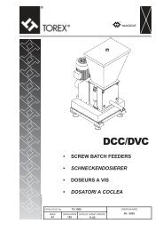
PROGRESSIVE SYSTEM<strong>SISTEMA</strong> <strong>DI</strong> <strong>LUBRIFICAZIONE</strong><strong>CENTRALIZZATA</strong>CENTRALIZED LUBRICATION SYSTEM<strong>SISTEMA</strong> PROGRESSIVOPROGRESSIVE SYSTEMCat. Code 3320950 - 06/2008
<strong>SISTEMA</strong> PROGRESSIVOCO<strong>DI</strong>CE IN<strong>DI</strong>CE NUMERICO PAGINACODE NUMERICAL INDEX PAGE3304001 ÷ 3304003 783304004 ÷ 3304005 793304006 ÷ 3304008 783304012 ÷ 3304017 786012030 ÷ 6012033 606012030 ÷ 6012033 616014200 ÷ 6014211 396014220 ÷ 6014231 396014260 ÷ 6014271 396015031 ÷ 6015032 336015050 ÷ 6015052 336015055 ÷ 6015057 336015060 ÷ 6015069 336015071 ÷ 6015074 336015076 ÷ 6015081 336015084 336015088 ÷ 6015089 336015103 336015105 ÷ 6015107 336015111 336015136 ÷ 6015144 336015146 336016010 6016011 366016014 366016020 ÷ 6016021 366016023 ÷ 6016026 366016030 366016033 ÷ 6016034 366016038 366016041 ÷ 6016044 366016049 366016052 366016054 ÷ 6016060 366016062 ÷ 6016063 366020001 ÷ 6020002 556020006 ÷ 6020007 556020009 556020017 556020022 556021001 ÷ 6021002 566021009 566021010 576021014 586021016 586027006 426027007 ÷ 6027008 416027009 ÷ 6027011 426027022 42CO<strong>DI</strong>CE IN<strong>DI</strong>CE NUMERICO PAGINACODE NUMERICAL INDEX PAGE6027064 ÷ 6027067 446027068 ÷ 6027069 416027071 426027085 416027105 416027108 446027161 426027193 ÷ 6027195 446027210 ÷ 6027212 426027224 446030002 546030004 546030010 476030012 516030018 466030024 506030026 516030030 546030034 466030036 ÷ 6030037 456030039 456030041 476030042 466030052 536030058 496030063 456030076 456030085 546030093 526030099 ÷ 6030103 526030115 456030126 ÷ 6030127 486030135 ÷ 6030136 486030145 476067374 ÷ 6067375 666072017 ÷ 6072019 66072020 86072021 ÷ 6072023 146072033 ÷ 6072050 76072053 ÷ 6072070 76072073 ÷ 6072090 76072101 ÷ 6072109 86072111 ÷ 6072119 86072121 ÷ 6072129 86072131 ÷ 6072139 86072141 ÷ 6072149 126072151 ÷ 6072159 126072161 ÷ 6072169 10IV
<strong>SISTEMA</strong> PROGRESSIVOCO<strong>DI</strong>CE IN<strong>DI</strong>CE NUMERICO PAGINACODE NUMERICAL INDEX PAGE7272002 457272003 457272003 467272006 477272007 457272007 467272008 ÷ 7272009 517272017 457272017 467272034 457272034 477272049 457272049 477272091 ÷ 7272092 487272096 ÷ 7272097 488042001 448062006 ÷ 8062008 58062006 628062008 628093003 818093006 818093009 408093009 818093030 238093030 278093036 ÷ 8093040 818093037 878093040 878093042 ÷ 8093044 818093039 758093042 758093043 248093046 238093046 248093047 758093046 ÷ 8093047 818093049 ÷ 8093051 818093053 ÷ 8093059 818093060 878093062 818093067 878094001 ÷ 8094014 828094020 ÷ 8094021 828097001 ÷ 8097007 818098001 ÷ 8098006 828098007 ÷ 8098008 878098017 ÷ 8098019 878102001 ÷ 8102021 85CO<strong>DI</strong>CE IN<strong>DI</strong>CE NUMERICO PAGINACODE NUMERICAL INDEX PAGE8102022 ÷ 8102025 868102026 ÷ 8102028 858102033 ÷ 8102042 858104001 ÷ 8104018 838104020 ÷ 8104025 838105001 ÷ 8105008 848120003 68124001 ÷ 8124007 838125003 ÷ 8125007 818125003 ÷ 8125007 828161050 ÷ 8161053 868125003 238125003 278125003 758125003 ÷ 8125004 878125004 238125004 248125004 278125004 758125005 238125005 248125005 758128004 338128004 368128016 338128026 338128050 ÷ 8128051 338132008 ÷ 8132010 778132017 ÷ 8132026 778132030 ÷ 8132034 778132043 ÷ 8132044 778132063 778133003 ÷ 8133004 788132063 778133007 808133010 808133021 788133025 ÷ 8133038 788133055 ÷ 8133058 808133066 ÷ 8133070 788133071 798133080 ÷ 8133081 798147015 408147019 408147029 408147031 408155001 ÷ 8155002 808155005 ÷ 8155024 80VI
PROGRESSIVE SYSTEMCO<strong>DI</strong>CE IN<strong>DI</strong>CE NUMERICO PAGINACODE NUMERICAL INDEX PAGE8155027 ÷ 8155035 808155037 ÷ 8155049 808155055 ÷ 8155057 808161055 ÷ 8161056 868161040 868161044 108161057 98161057 208161065 108161176 ÷ 8161177 208161179 208164077 818164272 ÷ 8164277 758169017 ÷ 8169024 838169025 ÷ 8169032 828169028 238176009 ÷ 8176014 738177008 ÷ 8177009 698183010 448183014 448186007 148186007 178186007 ÷ 8186009 98186015 ÷ 8186018 868213010 ÷ 8213011 118214142 378214157 378244002 ÷ 8244004 448249015 ÷ 8249016 828249020 ÷ 8249022 818249020 ÷ 8249022 828249022 878249024 818249024 828249024 238249024 278249024 878249025 828249026 ÷ 8249028 818249026 ÷ 8249028 828249026 878249027 238249027 248249027 878249028 238249028 248249061 108249075 10CO<strong>DI</strong>CE IN<strong>DI</strong>CE NUMERICO PAGINACODE NUMERICAL INDEX PAGE8249111 798249114 ÷ 8249120 868249220 ÷ 8249223 218249234 ÷ 8249237 218256002 738256007 818258146 668258150 668278003 558289005 868289007 868289012 ÷ 8289013 868289021 268289036 268289037 178289036 ÷ 8289037 98289038 ÷ 8289040 868289045 208289051 208289051 ÷ 8289054 868289084 ÷ 8289085 268289137 ÷ 8289140 198289137 ÷ 8289140 218289141 208289142 ÷ 8289145 198289142 ÷ 8289145 218302046 ÷ 8302053 258304014 ÷ 8304016 448306007 699036005 ÷ 9036006 809036008 ÷ 9036009 809036014 809036014 809106001 ÷ 9106002 909106010 ÷ 9106017 909107006 ÷ 9107009 789107012 789107014 ÷ 9107015 789107018 ÷ 9107022 789107024 789107030 ÷ 9107038 789107046 789107049 ÷ 9107059 789114001 ÷ 9114004 909114006 909118001 909118003 ÷ 9118006 909119001 ÷ 9119012 90VII
<strong>SISTEMA</strong> PROGRESSIVOCO<strong>DI</strong>CE IN<strong>DI</strong>CE NUMERICO PAGINACODE NUMERICAL INDEX PAGE9131002 ÷ 9131006 909131004 239131005 ÷ 9131006 239131005 ÷ 9131006 249131012 909131016 909133006 ÷ 9133008 809133007 809133011 ÷ 9133012 789151003 ÷ 9151004 809169032 55CO<strong>DI</strong>CE IN<strong>DI</strong>CE NUMERICO PAGINACODE NUMERICAL INDEX PAGE9169159 259176001 449241677 ÷ 9241678 809241691 209241934 559249007 799249010 ÷ 9249011 889249024 888218004 799300006 379300020 ÷ 9300021 37VIII
PROGRESSIVE SYSTEM<strong>SISTEMA</strong><strong>DI</strong> <strong>LUBRIFICAZIONE</strong>PROGRESSIVOPROGRESSIVELUBRICATIONSYSTEM
<strong>SISTEMA</strong> PROGRESSIVO<strong>SISTEMA</strong> PROGRESSIVONOTE GENERALIPROGRESSIVE SYSTEMGENERAL NOTESFUNZIONAMENTO DEL <strong>SISTEMA</strong> / SYSTEM RUNNING PMFPer visualizzare il funzionamento del sistema,premere il pulsante a destra.To see the system running,►press the push button on the right.Questo sistema utilizza una sola linea per distribuire il lubrificantee consente un controllo totale dell’impianto tramite un solodispositivo montato su uno qualsiasi degli elementi dosatori.Il principio di funzionamento di un dosatore progressivo è il seguente(vedi figura).Il lubrificante in pressione proveniente dalla pompa, entra nelpacco di dosatori progressivi composto da un minimo di tre elementie attraverso il condotto interno di mandata, arriva allaparte destra del pistoncino 1 spingendolo verso sinistra.Questo spostamento determina l’erogazione, attraverso l’uscitaD1, del lubrificante immagazzinato nella camera di dosaggiosinistra del primo elemento.Contemporaneamente si ha l’apertura del passaggio che permetteal lubrificante proveniente dalla linea di comandare il pistone2 muovendolo verso sinistra.Lo spostamento di questo pistone, oltre a far erogare il lubrificantedall’uscita S2, apre il passaggio che permette al pistone 3di eseguire la stessa operazione, con erogazione di lubrificantedall’uscita S3 ed apertura del passaggio che invia il lubrificantein pressione alla parte sinistra del pistone 1.In progressione si avrà lo spostamento degli altri due pistoniche completerà il ciclo di lubrificazione.Poiché il movimento di un pistone è la necessaria condizioneper il movimento del pistone successivo, tutti i dosatori progressividi un impianto, risultano collegati in serie e pertanto il bloccodel pistone di uno qualsiasi dei dosatori, anche se appartenentead un altro pacco, blocca automaticamente l’intero impianto.Questa caratteristica è molto importante per il controllo di unsistema centralizzato: basta infatti controllare con un microinterruttoreo con un reed magnetico o meglio con un sensoreinduttivo un’uscita qualsiasi di un dosatore per controllare tuttol’impianto.This system uses a single lubricant distribution line and allows acomplete control of the system using a single device that can beinstalled on any of the metering elements.A progressive metering device operates as follows (see figure).The pressurized lubricant coming from the pump enters theset of progressive metering elements consisting of a minimumof three elements and, through the internal deliveryduct, reaches the right-hand position of piston 1 pushing thisleftwards.This movement causes the supply, through outlet D1, of thelubricant that has been accumulated in the left-hand meteringchamber of the first element.At the same time, the passage allowing the lubricant to arrivefrom the line to activate piston 2, moving this leftwards,is opened.In addition to the supply of lubricant form outlet S2, the movementof this piston opens the passageway that allows piston3 to perform the same operating, with supply of lubricantfrom outlet S3 and opening the passageway the allowsthe pressurized lubricant to travel to the left-hand part ofpiston 1.The other two pistons that complete the lubrication cyclewill be moved in sequence. As the movement of a pistonis necessary to activate the next piston, all the progressivemetering elements of a system are connected in series.Therefore, the blocking of any of the pistons of the meteringelements, even those of another set, automatically blocksthe whole system.This characteristic is very important for the control of a centralizedsystem. The entire system can be controlled by monitoringany outlet of a metering element with a microswitchor magnetic reed or even better with an inductive sensor.
PROGRESSIVE SYSTEMESEMPI APPLICATIVIEXAMPLESIn figura è schematizzato un impianto a olio completo di elettropompaad ingranaggi tipo 6027 con 500 cm 3 /min. e pressione7 MPa.Diagram of an oil lubrication system equipped with a motorizedgear pump (model 6027) with output 500 cm 3 /min. atpressure of 7 MPa (1015 PSI).In figura è schematizzato un impianto progressivo completodi elettropompa a pistoni tipo 6015 con portata fino a 130cm 3 /min. e pressione fino a 35 MPa, e di microinterruttori dicontrollo ciclo.Diagram of a progressive lubrication system equipped withelectric pump (model 6015) with output up to 130 cm 3 /min.at pressure of 35 MPa (5075 PSI) with microswitch forcycle control.In figura è schematizzato un impianto misto progressivo, doppialinea. La pompa è tipo FXDUE da 240 cm 3 /min. - 50 MPa.Il controllo è effettuato da pressostato di fine linea e microinterruttorisui progressivi.Diagram of a mixed lubrication system, progressive anddual line. The pump used is an FXDUE type with output of240 cm 3 /min. at pressure of 50 MPa (7250 PSI).Cycle control is obtained by an end of line pressure switchand/or microswitches on the progressive distributors.
<strong>SISTEMA</strong> PROGRESSIVO<strong>DI</strong>STRIBUTORI PROGRESSIVI MODULARISERIE PMF / PMF0PROGRESSIVE MODULAR SYSTEMPMF / PMF0 SERIESIl sistema modulare PMF rappresenta, nel campo dellalubrificazione centralizzata, la soluzione tecnica più avanzatache consente: precisione e garanzia di dosaggio, flessibilitànell’assemblaggio dei blocchetti, intercambiabilità deidosatori, possibilità di intervento e modifica sul blocco inqualsiasi situazione e facilità di manutenzione.Il costo contenuto ha permesso a questo prodotto unimmediato successo fra gli utilizzatori.CARATTERISTICHE TECNICHE:Questi distributori modulari possono funzionare sia conlubrificante olio che grasso e precisamente i valori limite sono:PMF Progressive Modular System is the most advancedtechnical solution in the centralized lubrication field usingprogressive distributors.This new product is welcomed by users for its precision,consistency in metering, ease of assembly, interchangeabilityof metering blocks, modification blocks when necessary andits ease of maintenance and low cost.TECHNICAL CHARACTERISTICS:These modular distributors can operate both with lubricatingoil and with grease; the exact limit values are:viscosità minima olio:minimum oil viscosity:consistenza massima grasso:maximum grease consistency:pressione di funzionamento:operating pressure:pressione massima differenziale ammessa fra 2 uscite:differential pressure allowed between two outlets:temperatura di esercizio del lubrificante:lubricant operating temperature:numero di inversioni massime per minuto:maximum number of inversions for minutes:materiale:material:portate dosatori per uscita:metering units capacity per outlet:15 cSt220 ÷ 250 ASTMmax 40 MPa - min 1,5 MPa (max 5800 PSI - min. 217,5 PSI)25 MPa (3625 PSI) (grasso - grease)10 MPa (1450 PSI) (olio - oil)-30 °C to +100 °C con guarnizioni standard (with standard seals)-20 °C + 150 °C con guarnizioni in Viton (with Viton seals)500dosatore e base in acciaio zincato biancowhite galvanized steel metering units and base0,04 to 0,65 cm 3 /ciclo (cm 3 /cycle)
PROGRESSIVE SYSTEM<strong>DI</strong>STRIBUTORI PROGRESSIVI MODULARISERIE PMF / PMF0PROGRESSIVE MODULAR SYSTEMPMF / PMF0 SERIESLe connessioni di ingresso normali sono:1/4 BSP (a richiesta si possono fornire connessioni M 14 x 1 e 1/4 NPTF).Le connessioni di uscita normali sono:1/8 BSP (a richiesta si possono fornire connessioni M 10 x 1 e 1/8 NPTF).Common inlet connections are:1/4 BSP (M 14 x 1 and 1/4 NPTF connections can be supplied upon request).Common inlet connections are:1/8 BSP (M 10 x 1 and 1/8 NPTF connections can be supplied upon request).N° ElementiDosatoriN° MeteringElementsDimensioni Nominali. Tolleranza / ElementoNominal Dimensions. Tolerance for each Element+0 -0,05 mmN° ElementiDosatoriDimensioni Nominali. Tolleranza / ElementoNominal Dimensions. Tolerance for each Element+0 -0,05 mmPMF PMF0N° MeteringElementsPMF PMF0A B A B A B A B3 93,02 83,02 80,2 71,8 12 303,80 293,80 265,6 257,24 116,44 106,44 100,8 92,4 13 327,22 317,22 286,2 277,85 139,86 129,86 121,4 113 14 350,64 340,64 306,8 298,46 163,28 153,28 142 133,6 15 374,06 364,06 327,4 3197 186,70 176,70 162,6 154,2 16 397,48 387,48 348 339,68 210,12 200,12 183,2 174,8 17 420,90 410,90 368,6 360,29 233,54 223,54 203,8 195,4 18 444,32 434,32 389,2 380,810 256,96 246,96 224,4 216 19 467,74 457,74 409,8 401,411 280,38 270,38 245 236,6 20 491,16 481,16 430,4 422CodiceCodeABSPBBSPSede tuboTube seating8062008 1/4 1/8 Ø-e 88062007 3/8 3/8 conico Ø-e 108062006 1/8 1/8 conico Ø-e 68062005 1/4 1/4 conico Ø-e 8Filettatura entrataInlet Thread1/4 BSP PMF1/8 BSP PMF0 Tappo / plug 1/8 BSPCode 8186007
<strong>SISTEMA</strong> PROGRESSIVO<strong>DI</strong>STRIBUTORI PROGRESSIVI MODULARISERIE PMF / PMF0 - BASE ASSIEMATACOMPONENTI DELLA BASEIl gruppo base deve essere composto da una serie minima ditre elementi per effettuare una sequenza idraulica.FIG. Descrizione Codice PMF Codice PMF0A Base finale 6072019 6072502B Base intermedia 6072018 6072501C Base iniziale 6072017 6072500La base iniziale, unica per ogni gruppo, ha l’ingresso dellubrificante ed è costruita in modo da portare un dosatore.La base intermedia porta un dosatore ed è un elementovariabile in funzione dei punti da lubrificare. Concettualmentenon ha limitazioni di numero. La base finale è unica per ognigruppo ed ha funzione di chiudere il ciclo idraulico. È costruitain modo da portare un dosatore.PROGRESSIVE MODULAR SYSTEMPMF / PMF0 SERIES - BASE ASSEMBLYCOMPONENTS FOR THE BASEThe base unit must be composed at least by three elementsto allow a complete hydraulic sequence.FIG. Description PMF Code PMF0 CodeA Final base 6072019 6072502B Intermediate base 6072018 6072501C Initial base 6072017 6072500The initial base, one for each unit, has the lubricant inlet andis built to carry a metering unit.The intermediate base has a metering unit and is the variableelement according to the points to be lubricated. In theory,there is no limit to the number of such bases.The final base, one for each unit, has the purpose ofterminating the hydraulic cycle. It is built to carry a meteringelement.KIT RICAMBI: OR+VITI+FISSAGGIO+<strong>DI</strong>SCHETTIBASE ASSIEMATA PMF codice 8120003KIT SPARE PARTS: OR+SCREW+FASTENING+<strong>DI</strong>SKPMF BASE ASSEMBLY code 8120003N° ElementiDosatoriN° MeteringElementsBase Assiemata - Assembly BaseN° ElementiBase Assiemata - Assembly BaseFilettature: Entrata - UscitaPeso DosatoriFilettature: Entrata - UscitaThreads: Inlet OutletWeightThreads: Inlet Outletkg. N° MeteringBSP NPTF METRICO Elements BSP NPTF METRICOPesoWeightkg.3 6072203 6072223 6072243 1,4 12 6072212 6072232 6072252 4,464 6072204 6072224 6072244 1,74 13 6072213 6072233 6072253 4,85 6072205 6072225 6072245 2,08 14 6072214 6072234 6072254 5,146 6072206 6072226 6072246 2,42 15 6072215 6072235 6072255 5,487 6072207 6072227 6072247 2,76 16 6072216 6072236 6072256 5,828 6072208 6072228 6072248 3,1 17 6072217 6072237 6072257 6,169 6072209 6072229 6072249 3,44 18 6072218 6072238 6072258 6,510 6072210 6072230 6072250 3,78 19 6072219 6072239 6072259 6,8411 6072211 6072231 6072251 4,12 20 6072220 6072240 6072260 7,18BASE ASSIEMATA PMF0N° ElementiDosatoriN° MeteringElementsPMF0 ASSEMBLY BASEBase Assiemata - Assembly BaseN° ElementiBase Assiemata - Assembly BaseFilettature: Entrata - UscitaPeso DosatoriFilettature: Entrata - UscitaThreads: Inlet OutletWeightThreads: Inlet Outletkg. N° MeteringBSP NPTF METRICO Elements BSP NPTF METRICOPesoWeightkg.3 6072543 6072613 6072633 0,92 12 6072552 6072622 6072642 2,804 6072544 6072614 6072634 1,13 13 6072553 6072623 6072643 3,005 6072545 6072615 6072635 1,33 14 6072554 6072624 6072644 3,166 6072546 6072616 6072636 1,54 15 6072555 6072625 6072645 3,427 6072547 6072617 6072637 1,75 16 6072556 6072626 6072646 3,638 6072548 6072618 6072638 1,96 17 6072557 6072627 6072647 3,849 6072549 6072619 6072639 2,17 18 6072558 6072628 6072648 4,0510 6072550 6072620 6072640 2,38 19 6072559 6072629 6072649 4,2611 6072551 6072621 6072641 2,59 20 6072560 6072630 6072650 4,47Kit ricambi: OR + viti fissaggio + dischetto (codice 8120003). Spares kit: OR + fixing screws + washer (code 8120003).
PROGRESSIVE SYSTEM<strong>DI</strong>STRIBUTORI PROGRESSIVI MODULARISERIE PMF / PMF0 - ASSIEME COMPLETOPROGRESSIVE MODULAR SYSTEMPMF / PMF0 SERIES - ASSEMBLYASSIEME COMPLETO <strong>DI</strong> BASE + DOSATORI PMFPMF ASSEMBLY BASE + METERING ELEMENTSN° ElementiDosatoriN° MeteringElementsAssieme Completo BaseN° Elementi Assieme Completo BaseAssembly + Elements Peso Dosatori Assembly + ElementsFilettature: Entrate - uscita WeightFilettature: Entrate - uscitaThreads: Inlet - Outlet kg. N° Metering Threads: Inlet - OutletBSP NPTF METRICO Elements BSP NPTF METRICOPesoWeightkg.3 6072033 6072053 6072073 2,35 12 6072042 6072062 6072082 8,204 6072034 6072054 6072074 3,00 13 6072043 6072063 6072083 8,855 6072035 6072055 6072075 3,65 14 6072044 6072064 6072084 9,506 6072036 6072056 6072076 4,30 15 6072045 6072065 6072085 10,157 6072037 6072057 6072077 4,95 16 6072046 6072066 6072086 10,808 6072038 6072058 6072078 5,60 17 6072047 6072067 6072087 11,459 6072039 6072059 6072079 6,25 18 6072048 6072068 6072088 12,110 6072040 6072060 6072080 6,90 19 6072049 6072069 6072089 12,7511 6072041 6072061 6072081 7,55 20 6072050 6072070 6072090 13,40ASSIEME COMPLETO <strong>DI</strong> BASE + DOSATORI PMF0PMF0 ASSEMBLY BASE + METERING ELEMENTSN° ElementiDosatoriN° MeteringElementsAssieme Completo BaseN° Elementi Assieme Completo BaseAssembly + Elements Peso Dosatori Assembly + ElementsFilettature: Entrate - uscita WeightFilettature: Entrate - uscitaThreads: Inlet - Outlet kg. N° Metering Threads: Inlet - OutletBSP NPTF METRICO Elements BSP NPTF METRICOPesoWeightkg.3 6072563 6072653 6072673 1,58 12 6072572 6072662 6072682 4,464 6072564 6072654 6072674 2,00 13 6072573 6072663 6072683 4,85 6072565 6072655 6072675 2,40 14 6072574 6072664 6072684 5,146 6072566 6072656 6072676 2,75 15 6072575 6072665 6072685 5,487 6072567 6072657 6072677 3,15 16 6072576 6072666 6072686 5,828 6072568 6072658 6072678 3,50 17 6072577 6072667 6072687 6,169 6072569 6072659 6072679 3,88 18 6072578 6072668 6072688 6,510 6072570 6072660 6072680 3,24 19 6072579 6072669 6072689 6,8411 6072571 6072661 6072681 4,60 20 6072580 6072670 6072690 7,18
<strong>SISTEMA</strong> PROGRESSIVO<strong>DI</strong>STRIBUTORI PROGRESSIVI MODULARISERIE PMF / PMF0ELEMENTI DOSATORIGli elementi dosatori si montano sulla base tramite due viti difissaggio fornite con gli elmenti.Gli elementi dosatori sono disponibili con diverse portate: da0,04 a 0,65 cm 3 per ciclo, per uscita.Elementi dosatori ponte consentono di trasferire la portata diun elemento a quello successivo, eliminando così giunzioniesterne.Elementi by-pass consentono di creare coppie di puntidi riserva da inserire successivamente nell’impianto, o dieliminare coppie di punti non utilizzabili.Sono disponibili elementi, dosatori completi di controllo dibuon funzionamento: magnetico o visivo.Tutti gli elementi, compreso il by-pass, hanno le stessedimensioni di fissaggio e sono intercambiabili nelle diverseposizioni del gruppo.PROGRESSIVE MODULAR SYSTEMPMF / PMF0 SERIESMETERING ELEMENTSThe metering elements are assembled on the base by meansof fixing screws supplied with the elements.Metering elements having various capacities are available:from 0,04 to 0,65 cm 3 per cycle, per outlet.Bridge metering elements permit the transfer of the outputof one element to the next successive one, allowing theelimination of external junctions.Bypass metering elements allow the creation of reservepoints for future expansion of the system or the eliminationof pairs of points no longer required. Metering elements withmagnetic or visual performance controls are available.All the elements, including the bypass, have the samesecuring dimensions and are interchangeable in the variouspositions of the unit.Portataper ogni uscitaOutputfor each OutletDosatori PMFPMF MeteringElements1 o 2 Uscite / OutletsDosatori Ponte PMF con Portata al Successivo ElementoPMF Bridge Metering Elements with Output into the Next Elementcm 3cubicinchesSiglaMarkCodiceCodeSiglaMarksinistraleftCodiceCodesinistra - destraleft - rightSiglaMarkCodiceCodeSiglaMarkdestrarightCodiceCode0,04 0,002 PMF 04 6072101 PMF 04L 6072111 PMF 04LR 6072121 PMF 04R 60721310,08 0,005 PMF 08 6072102 PMF 08L 6072112 PMF 08LR 6072122 PMF 08R 60721320,16 0,010 PMF 16 6072103 PMF 16L 6072113 PMF 16LR 6072123 PMF 16R 60721330,25 0,015 PMF 25 6072104 PMF 25L 6072114 PMF 25LR 6072124 PMF 25R 60721340,35 0,021 PMF 35 6072105 PMF 35L 6072115 PMF 35LR 6072125 PMF 35R 60721350,40 0,025 PMF 40 6072106 PMF 40L 6072116 PMF 40LR 6072126 PMF 40R 60721360,50 0,030 PMF 50 6072107 PMF 50L 6072117 PMF 50LR 6072127 PMF 50R 60721370,60 0,036 PMF 60 6072108 PMF 60L 6072118 PMF 60LR 6072128 PMF 60R 60721380,65 0,040 PMF 65 6072109 PMF 65L 6072119 PMF 65LR 6072129 PMF 65R 6072139ELEMENTO BY-PASS PMF: SIGLA X - CO<strong>DI</strong>CE 6072020 PMF BY-PASS ELEMENT: MARK X - CODE 6072020Portataper ogni uscitaOutputfor each OutletDosatori PMFPMF MeteringElements1 o 2 Uscite / OutletsDosatori Ponte PMF con Portata al Successivo ElementoPMF Bridge Metering Elements with Output into the Next Elementcm 3cubicinchesSiglaMarkCodiceCodeSiglaMarksinistraleftCodiceCodesinistra - destraleft - rightSiglaMarkCodiceCodeSiglaMarkdestrarightELEMENTO BY-PASS PMF0: SIGLA X - CO<strong>DI</strong>CE 6072503 PMF0 BY-PASS ELEMENT: MARK X - CODE 6072503CodiceCode0,04 0,002 PMF0 04 6072504 PMF 04L 6072510 PMF0 04LR 6072530 PMF0 04LR 60725200,08 0,005 PMF0 08 6072505 PMF 08L 6072511 PMF0 08LR 6072531 PMF0 08LR 60725210,16 0,010 PMF0 16 6072506 PMF 16L 6072512 PMF0 16LR 6072532 PMF0 16LR 60725220,25 0,015 PMF0 25 6072507 PMF 25L 6072513 PMF0 25LR 6072533 PMF0 25LR 6072523Peso dei singoli elementi: PMF0: 0,20 Kgs. - PMF: 0,31 Kgs.Single element weight: PMF0: 0,20 Kgs. - PMF: 0,31 Kgs.
PROGRESSIVE SYSTEM<strong>DI</strong>STRIBUTORI PROGRESSIVI MODULARISERIE PMF / PMF0<strong>DI</strong>SPOSITIVO PER SOMMARE LE PORTATEPROGRESSIVE MODULAR SYSTEMPMF / PMF0 SERIESDEVICE FOR JOINING THE CAPACITIESTappo Giallo / Yellow Plug: 8289036 Tappo Bianco / White Plug: 8289037RondellaWasher:8161057UscitaOutletUscitaOutletBSPTappo / PlugNPTFMetricoMetric8186007 8186008 8186009È possibile sommare le due portate di uno stesso elemento,sostituendo il tappo giallo con il tappo bianco, come illustratonel disegno, togliendo inoltre la rondella di alluminio codice8161057.In questo caso, non si avranno mai due uscite dalla basecorrispondente; per tappare le uscite che non si voglionoutilizzare, basterà chiuderle con il tappo scegliendo l’adattafilettatura.IN<strong>DI</strong>CATORI <strong>DI</strong> PRESSIONEIt is possible to join the two capacities of the same element,by replacing the yellow plug with the white plug, as illustratedin the drawing, and taking off the washer code8161057.Once converted to a single outlet, either outlet in thebase not utilized can be closed off with a closing plug ofthe appropriate thread.PRESSURE IN<strong>DI</strong>CATORSCaratteristiche / CharacteristicsFilettaturaThreadPressione maxMax pressureNormaleNormalCon MemoriaWith MemoryBSP Mpa PSI Code Code2 290 7044005 –3 435 7044006 70430055 725 7044007 70430061/87,5 1087,5 – 704300710 1450 7044008 704300815 2175 7044009 704300920 2900 7044010 704301025 3625 7044011 7043011IN<strong>DI</strong>CATORE <strong>DI</strong> PRESSIONEGli indicatori di pressione vengono utilizzati per il controllodella pressione nella tubazione principale o secondaria, sonoprevisti per pressioni fino a 25 MPa.Nei tipi con astina e molla la pressione agisce su un pistoncino,rettificato e lappato che sposta l’astina.L’astina esce quando si raggiunge la pressione di taratura;rientra quando la pressione scende sotto tale valore.IN<strong>DI</strong>CATORE <strong>DI</strong> PRESSIONE A MEMORIAQuesto dispositivo è molto utile per il controllo della lineasecondaria di alimentazione.L’astina X esce quando, sulla tubazione dove viene impiegatol’indicatore, si verifica un anomalo aumento della pressionedovuto all’occlusione dell’entrata del lubrificante nelsupporto.Il dispositivo non permette il ritorno dell’astina X se non previosgancio della leva, segnalando all’operatore l’irregolarità difunzionamento(azionare la leva verso l’alto per il ripristino).PRESSURE IN<strong>DI</strong>CATORSPressure indicators are used to check the pressure in themain or secondary pipes and are available for pressures upto 25 MPa (3625 PSI).In pin and spring type pressure indicators, the pressure actson a ground and lapped piston which moves the pin.Pin W exits when the calibration pressure is reached. Itretracts when the pressure drops below this value.MEMORY TYPE PRESSURE IN<strong>DI</strong>CATORThis device is very useful for controlling the secondary supplyline. Pin X exits in the case of an irregular pressure increase inthe pipe on which the indicator is installed, due to the blockingof the lubricant infeed to the support.The device does not permit retraction of pin X if the lever thatinforms the operator of the alarm (move lever up to reset) hasnot been released.
<strong>SISTEMA</strong> PROGRESSIVO<strong>DI</strong>STRIBUTORI PROGRESSIVI MODULARISERIE PMF / PMF0MICROINTERRUTTORE PER CONTROLLO MOVIMENTOPISTONE DEI DOSATORI PROGRESSIVI TIPO PMFPROGRESSIVE MODULAR SYSTEMPMF / PMF0 SERIESMICROSWITCH FOR THE PISTON MOVEMENT CONTROLOF THE PMF <strong>DI</strong>STRIBUTORSABCPortataOutputPMFGuarnizioneSealCodeMicrointerruttoreMicroswitchCodeRaccordoConnectionCodeFig. A B C0.04 - 0.25 8161044 6213001 82490750.35 - 0.65 8161065 6213002 8249061CARATTERISTICHE TECNICHE:Alimentazione elettrica: 250V 5A a.c. 24V 5A d.c.Lunghezza cavo:1 mtGrado di protezione (custodia): IP 55Temperatura di esercizio: da -20 °C a +85 °CForza di manovra massima: 0.5NDurata meccanica:10 6 cicli circaTECHNICAL CHARACTERISTICS:Electrical supply:250V 5A a.c. 24V 5A d.c.Cable length:1 mtProtection degree (case): IP 55Operating temperature: from -20 °C a +85 °CMaximum manoeuvre effort: 0.5NMechanical life span: approx. 10 6 cyclesEsempio di funzionamento del dosatore PMF completo di microcontattoOperating example of PMF with microswitchMarroneBrownNeroBlackBluBlueSchema collegamentiConnections diagramsDOSATORI COMPLETI <strong>DI</strong> MICROCONTATTOMICROSWITCH <strong>DI</strong>STRIBUTORSPortataPMF PMF0 PMFOutput (cm 3 ) con Microcontatto / Microswitch con Microcontatto / Microswitch con Connettore / with Connector0,04 6072161 6072534 60727010,08 6072162 6072535 60727020,16 6072163 6072536 60727030,25 6072164 6072537 60727040,35 6072165 - 60727050,40 6072166 - 60727060,50 6072167 - 60727070,60 6072168 - 60727080,65 6072169 - 607270910
PROGRESSIVE SYSTEM<strong>DI</strong>STRIBUTORI PROGRESSIVI MODULARISERIE PMF / PMF0SENSORE <strong>DI</strong> PROSSIMITÀ INDUTTIVOCO<strong>DI</strong>CE 8213010 (TIPO NPN) CO<strong>DI</strong>CE 8213011 (TIPO PNP)PROGRESSIVE MODULAR SYSTEMPMF / PMF0 SERIESINDUCTIVE PROXIMITY SENSORCODE 8213010 (NPN TYPE) CODE 8213011 (PNP TYPE)Lunghezza cavo 2 mtCable Lenght 2 mtLed RossoRed LedGrano di FermoStop PlugDado per RegolazioneGrub ScrewQuesto tipo di controllo è costituito da un sensore di prossimitàinduttivo per corrente continua.Tensione di alimentazione 10 - 30V d.c.Max corrente permanente 200 mA protezione IP 67Temperature di funzionamento da -25 °C a +75 °C.Materiale custodia acciaio INOX, il tutto montato su uncorpo in alluminio nel quale scorre, azionato dall’astina deldosatore PMF, un pistone in acciaio. Il sensore segnala adun’apparecchiatura il regolare funzionamento del dosatore,oppure il numero di cicli effettuati.Un led, posto sul sensore, consente di controllare ilfunzionamento anche visivamente. Il sensore di prossimitàcompleto viene fornito già tarato. Potrebbe capitare che almomento dell’installazione la taratura risulti scarsa. In questocaso allentare i due dadi, regolare la distanza del sensore,azionare l’astina, verificare il regolare funzionamento permezzo del led e poi bloccare i dadi. Nel caso di impiantopreesistente nel quale fosse montato il dispositivo visivodi controllo del movimento pistone, è possibile montare ilcontrollo con sensore senza sostituire pezzi o scollegare letubazioni. Calzare il sensore sul raccordo stesso.Poi eventualmente, se occorresse, procedere alla taraturacorsa.This type of control is energized by a direct current inductiveproximity sensor.Power supply voltage:10 - 30V d.c.Max. permanent current: 200 mA protection IP 67Operating temperatures: from -25 °C to +75 °CThe sensor body is manufactured from aluminium withstainless steel interval components.When secured to a PMFmetering element, during a lubrication cycle, the pin on thePMF element makes contact with the plunger in the sensor,providing a signal indicating the conclusion of a successfulcycle. A LED on the sensor provides a visual indication of theconclusion of the successful cycle. The complete proximitysensor is supplied preset. In the event that the sensor isincorrectly positioned on the PMF element, loosen the twogrub screws and readjust the position of the sensor. Checkwith the LED that it is working correctly before re-securingthe grub screws. It is possible to fit the sensor to an existingsystem, providing a PMF element has an indicator pin fiitted.If this is not the case, a PMF element with sensor can beinstalled in place of an existing element without any changesto the pipework.Fit the sensor into the connector and, using the two pins,anchor the sensor to the connector. Then, if necessaryproceed with the stroke calibration.Schema collegamentiConnections diagramPortataOutput(cm 3 )PMFcon Sensore NPNwith NPN SensorPMFcon Sensore PNPwith PNP SensorPMF0con Sensore NPNwith NPN SensorPMF0con Sensore PNPwith PNP SensorCodice / Code Codice / Code Codice / Code Codice / Code0,04 6072171 6072601 6072538 60725810,08 6072172 6072602 6072539 60725820,16 6072173 6072603 6072540 60725830,25 6072174 6072604 6072541 60725840,35 6072175 6072605 - -0,40 6072176 6072606 - -0,50 6072177 6072607 - -0,60 6072178 6072608 - -0,65 6072179 6072609 - -11
<strong>SISTEMA</strong> PROGRESSIVO<strong>DI</strong>STRIBUTORI PROGRESSIVI MODULARISERIE PMF / PMF0CONTROLLO <strong>DI</strong> CICLO CON ASTINA VISIVAPROGRESSIVE MODULAR SYSTEMPMF / PMF0 SERIESWITH IN<strong>DI</strong>CATING PIN FOR CYCLE CONTROLCONTROLLO <strong>DI</strong> CICLO CON CONTATTO MAGNETICOUn magnete permanente applicato al pistone aziona un contatto“reed” (con contatto NA) che se connesso ad un circuito elettronicopuò conteggiare fino a 500 movimenti al minuto. Il contatto reed èinserito in un contenitore a tenuta ed è facilmente sostituibile.CARATTERISTICHE TECNICHE:ABPortateOutput(cm 3 )WITH N.O. REED SWITCHACon Astina Visiva / With Indicating PinPMFPMF00,04 6072151 60725140,08 6072152 60725150,16 6072153 60725160,25 6072154 60725170,35 6072155 -0,40 6072156 -0,50 6072157 -0,60 6072158 -0,65 6072159 -PortateOutput(cm 3 )BContatto magnetico / Reed SwitchPMFPMF00,04 6072141 60725240,08 6072142 60725250,16 6072143 60725260,25 6072144 60725270,35 6072155 -0,40 6072146 -0,50 6072147 -0,60 6072148 -0,65 6072149 -A permanent magnet on the piston operates a “reed” switch(with N.O. switch). If the switch is connected to an electroniccircuit, it can count up to 500 movements per minute. The reedswitch is placed in a hermetic box and is very easy to replace.TECHNICAL CHARACTERISTICS:Contatto magneticoReed switchCode 6158001CaratteristicheMain electric featuresTensione max commutabile/Max. voltageCorrente max commutabile/Max. currentPotenza maxcommutabilecontinua/directCondizioni del ContattoSwitch StateNA Normalmente ApertoN.O. Normally OpenConformità Internazionale del ContattoSwitch International ConformityFORM A-ASA-Valori elettrici, meccanici, termici ammissibiliElectrical, mechanical and thermal values220 V a.c.3 A50 WMax. power alternata/alternate 50 VAResistenza max/Max. resistanceTempo di commutazioneSwitching timeFrequenza max/Max. FrequencyInserimento a - c •=3msConnection o - c •=3ms100 mΩ320 Hz1 <strong>DI</strong>NDisinserimento c - a •=0,07 msDisconnection c - o •=0,07 msDurata max del contatto • / Max. Switch life • 500 milioni di cicli operativi/500 million cyclesCampo di temperatura di lavoro del contatto •Switch working temperature field •da (-55°C) a (+150°C)/from (-55°C) up to (+150°C)• condizioni normali di carico• normal load conditions• c=chiuso a=aperto• c=closed a=open12
PROGRESSIVE SYSTEM<strong>DI</strong>STRIBUTORI PROGRESSIVI MODULARISERIE PMF ARIA - OLIOPMF AIR-OIL PROGRESSIVEMODULAR SYSTEM<strong>DI</strong>STRIBUTORI <strong>DI</strong> <strong>LUBRIFICAZIONE</strong>PROGRESSIVI MODULARI SERIE PMF ARIA - OLIO(BASE IN ALLUMINIO COLORE AZZURRO)Pur mantenendo invariato il sistema di lubrificazione progressivotradizionale (PMF) i dosatori aria - olio sono particolarmenteindicati per la lubrificazione dei supporti di mandrini rotanti adalta velocità, per la lubrificazionedi organi operanti ad alte temperature e dei supporti delle gabbiedi laminazione. Dimensioni, ingombri e portate sono identichea quelle di dosatori PMF. Si distingue da quest’ultimo solo perla sua base che è in alluminio con colorazione azzurra.PRINCIPIO <strong>DI</strong> FUNZIONAMENTOIl lubrificante viene inviato in quantità accuratamente misurata daidosatori alle rispettive uscite sulle quali sono montati gli specialiraccordi di miscelazione. Questi raccordi sono collegati direttamentecon un continuo flusso di aria compressa max 1,2 MPa, la qualeinvestendo l’olio in uscita lo fraziona in minutissime particelle e lotrasporta fino al punto da lubrificare. In caso di miscelazione finissimao in presenza di tubazioni molto lunghe, un terminale miscelatoremontato sul punto da lubrificare, rigenera nuovamente la miscela diolio e aria. Con questo sistema aria - olio si ha un notevole risparmiosul consumo di lubrificante, in quanto è possibile incrementare gliintervalli di pausa tra un ciclo e l’altro, ed aumentare quindi la vitamedia degli elementi lubrificati perché tutte le superfici interessatevengono investite dal flusso nebulizzato. Qualora l’impiego dellubrificante miscelato fosse limitato a pochi punti si può escludere unodei passaggi del flusso aria con un tappo. In questo modo avremotutte le uscite di un lato con lubrificazione normale e le uscite dellato opposto con lubrificazione miscelata.PMF AIR - OIL PROGRESSIVE MODULARLUBRICATING SYSTEMS(BLUE COLOUR ALUMINUM BASE)The basic design of this system is similar to the PMFprogressive, but with the inclusion of airways to enable themixing of oil and air. This system is highly suited to highspeed spingle and bearing lubrication, and spray lubricationof chains and gears. The overall dimensions and outputs areidentical to the PMF distributors. They can be identified by theblue aluminium base.OPERATING PRINCIPLEThe lubricant (oil) is delivered from the metering blockin the appropriate outlet. The outlet may have a specialmixing connection (see page 14). Compressed air flowscontinuously through the base of the progressive block to thepoint of delivery (max. air pressure 1,2 MPa - 174 PSI). Theair breaks the delivered oil into tiny particles and migrates itto the exit point. By regulating air pressure and flow of air, fogcan be avoided. This air-oil system offers great savings inthe consumption of lubricant, since the interval time can beincreased due to the cooling effect of the air and the efficientdelivery the lubricant. Should the use of the air-oil lubricant belimited to only a few points, one of the two air flow passagescan be blocked using a plug. In this manner the output of thenormal lubrication will be obtained on one side and the outputof the air-oil lubrication will be obtained on the opposite side.13
<strong>SISTEMA</strong> PROGRESSIVO<strong>DI</strong>STRIBUTORI PROGRESSIVI MODULARISERIE PMF ARIA - OLIOPMF AIR-OIL PROGRESSIVEMODULAR SYSTEMDimensioni d’ingombroOverall dimensionsEntrata olioOil inlet1/8 BSPEntrata ariaAir inletSCELTA DELLA SOLA BASE ASSIEMATACHOICE OF THE ASSEMBLY BASEN° Elementi DosatoriN° Metering ElementsCodice BaseBase CodeQuote /DimensionsA B3 6072303 93.02 83.024 6072304 116.44 106.445 6072305 139.86 129.866 6072306 163.28 153.28SCELTA DEI SINGOLI ELEMENTIBase Iniziale Codice 6072021Base Intermedia Codice 6072022Base Finale Codice 6072023Elementi dosatori PMF da 0.04 a 0.65 cm 3 :per la loro scelta vedere a pagina 8.CHOICE OF THE SINGLE ELEMENTSInitial Base Code 6072021Intermediate Base Code 6072022Final Base Code 6072023For the choice of PMF 0.04 to 0.65 cm 3metering elements, see page 8.SCELTA TERMINALI <strong>DI</strong> MISCELAZIONECHOICE OF MIXTURING TERMINALSPos.N°123456DescrizioneDescriptionRaccordo di uscita per solo olioExit connection for oil onlyRaccordo di uscita miscelatore aria -olioExit connection for air -oil mixerTappo esclusione uscitaExit exclusion plugTappo esclusione dell’ingresso ariaAir entry exclusion plusTerminale per miscelazione fine (atomizzatore)Terminal for fine mixing (atomiser)Terminale per miscelazione grossolana (spruzzo)Terminal for heavier mixing (spray)CodiceCode6100002610000162890018186007609300260930037 Terminale per solo olio Terminal for oil only 609300114
PROGRESSIVE SYSTEM<strong>DI</strong>STRIBUTORI PROGRESSIVI MODULARI PMFPER SISTEMI MONOLINEA AD INVERSIONEPILOTATA DEL FLUSSOPMF PROGRESSIVE MODULAR SYSTEMFOR FLOW DRIVEN INVERSION SYSTEMSFOR SINGLE-LINEUscite / Outlets 1/8 BSPQuote nominali / Nominal DimensionsN° Elementi Dosatori Quote DimensionsN° Metering Elements A B1 69.60 59.602 93.20 83.023 116.44 106.444 139.86 129.865 163.28 15.286 186.70 176.707 210.12 200.128 233.54 223.549 256.96 246.9610 280.38 270.38DOSATORE A 3 ELEMENTI CO<strong>DI</strong>CE 6072413 3 ELEMENTS METERING BLOCK - CODE 6072413N° Elementi DosatoriN° Metering ElementsAssieme CompletoComplete AssemblySolo Basi AssiemateAssembled Base Only1 6072411 60724012 6072412 60724023 6072413 60724034 6072414 60724045 6072415 60724056 6072416 60724067 6072417 60724078 6072418 60724089 6072419 607240910 6072420 6072410Elementi dosatori Metering Elements (pag. 8)Code 6072421Elemento con pistoneservocomandoElement withservo - control pistonCode 6072400Elemeto selezionatoreSenso flussoSelector basedirection of flowValvole di RitegnoCheck ValvesUscite / Outlets 1/8 BSPBase AssiemataAssembled baseSpurgo AriaAir VentPer escludere un’uscita prevedere il grano codice 8186007 esostituire il tappo giallo con il tappo bianco codice 8289037 (vedipag. 9). I codici indicati della sola base assiemata sono compostidalla base finale, basi intermedie, base iniziale (selezionatrice)ed elemento servocomando. Mentre i codici di assieme completoservono solo per richiedere il prezzo. In fase di ordine, specificarein base al numero degli elementi il codice della base ed i singolielementi di dosaggio PMF che devono comporre il paccopartendo da destra verso sinistra. Attenzione! In questo sistemadi lubrificazione ad inversione di flusso, il primo elemento (PMF65) non è un elemento dosatore. Allo stesso modo le foratureda 1/8 BSP poste nella base iniziale servono alternativamentecome entrata del lubrificante. Grazie alla modularità del dosatoreprogressivo PMF è possibile, sostituendo la base iniziale ed ilprimo elemento di dosaggio trasformare un pacco di dosatoritradizionali in un sistema ad inversione di flusso come questo.To by-pass an outlet, use plug code 8186007 and replace theyellow plug with the white plug code 8289037 (see pag. 9).The codes indicated for base only consist of the final base,intermediate bases, initial base (selector) and servo-controlelement, whereas the complete assembly codes are usedonly to request the price.When ordering, specify, according tothe number of elements, the code of the baseand the singlePMF metering elements which are to make up the set, startingfrom the right and moving leftwards. Warning! In this flowinversion lubrication system, the first element (PMF 65) is nota metering element. Similarly, the 1/8 BSP holes in the initialselector base may be used alternatively as the lubricant inlet.The modular construction of the PMF progressive systemmakes it possible to convert a set of convertional meteringelements into a flow-inversion system of this type simply byreplacing the initial base and the first metering element.15
<strong>SISTEMA</strong> PROGRESSIVO<strong>DI</strong>STRIBUTORI PROGRESSIVI MODULARI PMFPER SISTEMI MONOLINEA AD INVERSIONEPILOTATA DEL FLUSSOPMF PROGRESSIVE MODULAR SYSTEMFOR FLOW DRIVEN INVERSION SYSTEMSFOR SINGLE-LINEFig. 1Fig. 2Fig. 3Fig. 416
PROGRESSIVE SYSTEM<strong>DI</strong>STRIBUTORI PROGRESSIVI MODULARI PMFPER SISTEMI MONOLINEA AD INVERSIONEPILOTATA DEL FLUSSOPMF PROGRESSIVE MODULAR SYSTEMFOR FLOW DRIVEN INVERSION SYSTEMSFOR SINGLE-LINESCHEMA <strong>DI</strong> FUNZIONAMENTO<strong>DI</strong>AGRAM FUNCTIONINGFigura 1: Il lubrificante in pressione muove il pistone selezionatoredi passaggio PV ed il pistone servocomando PS verso destra;quest’ultimo apre il passaggio al lubrificante consentendogli dispostare verso destra; il pistone P1 determinando l’erogazionedel lubrificante attraverso l’uscita 1a e progressivamentel’apertura del condotto, che sposterà verso destra il pistone P2.Figura 2: Il pistone P2 spostandosi comanda l’erogazione dellubrificante attraverso l’uscita 2a. Dato che il pistone è l’ultimodel blocco, determinerà il passaggio del lubrificante attraversola valvola di non ritorno V1 ad altri dosatori successivioppure in ritorno al serbatoio, completando in questo modoil primo mezzo ciclo di lubrificazione. Il lubrificante, prima discaricarsi in serbatoio incontra una valvola strozzatrice VSche opportunamente tarata, causa un innalzamento dellapressione registrata dal pressostato FL che per mezzo di unsegnale elettrico aziona l’invertitore I ottenendo l’inversione delflusso del lubrificante.Figura 3: Una volta azionato l’invertitore, il flusso del lubrificanteattraverso la stessa linea arriva al pacco dosatori dalla parteopposta e con la stessa procedura e sequenza sposterà ilpistone selezionatore PV, il pistone servocomando PS edi pistoni P1 e P2 verso sinistra, effettuando così il secondomezzo ciclo di lubrificazione tramite le uscite 1b e 2b.Figura 4: Completato il ciclo di lubrificazione, il lubrificantepassa attraverso la valvola di non ritorno V2 e come già illustrato,per mezzo della valvola strozzatrice VS e del pressostato FLaziona l’invertitore I predisponendolo per il successivo ciclo.Dall’illustrazione e dalla spiegazione si può capire che conquesto sistema progressivo, a differenza di quello tradizionale,è possibile dosare il lubrificante con estrema precisione, perchédopo ogni spostamento dei pistoni il lubrificante in eccessoviene scaricato completamente nel serbatoio.In tal modo aumenta la garanzia di funzionamento delmacchinario riducendo anche ogni spreco di lubrificante.Figure 2: The under pressure lubricant moves to the rightof the PV passage selector piston and the PS servo-controlpiston. This position opens the flow of lubricant, so that pistonP1 can move to the right with the consequent supply of thelubricant through outlet 1a and gradual opening of the duct,which will move to the right of piston P2.Figure 2: movement of P2 moves the lubricant supply throughoutlet 2a.As this piston is the last of the set, it will allow lubricant to passthrough the check valve V1 to other subsequent meteringblocks or return to the tank completing the first lubrication half- cycle. Before draining into the tank, the lubricant meets anappropriately calibrated VS throttle valve which causes anincrease in the pressure indicated by the pressure switch FLwhich, by means of an electrical signal, activates inverter Iwith consequent inversion of the lubricant flow.Figure 3: Once the flow inverter has been activated, theflow of lubricant, through the same line, arrives at the set ofmetering blocks from the apposite side and, with the sameprocedure and sequence, will move leftwards selector pistonPV, servo - control piston PS and pistons P1 and P2, therebyperforming the second lubrication half - cycle through outlets1b and 2b.Figure 4: After completion of the lubrication cycle, the lubricantpasses through check valve V2 and, as already illustrated,activates the inverter by means of the VS throttle valve andpressure switch FL, preparing it for the next cycle.It is clear, from the above illustration and explanations, thatthis progressive system, unlike conventional system, allowsextremely precise metering of the lubricant since all theexcess lubricant is drained into the tank after each movementof the pistons.Improving the operation of machinery and reducing possiblewastage of lubricant.17
<strong>SISTEMA</strong> PROGRESSIVO<strong>DI</strong>STRIBUTORI PROGRESSIVI SERIALIMONOBLOCCO DFM-DFMXDESCRIZIONE:I distributori progressivi della serie DFM e DFMX sono una unità diripartizione e di dosaggio destinate ad un impianto di lubrificazionecentralizzata a sequenza seriale. Essi consentono, per azione diuna serie di pistoni che si posizionano nelle loro sedi, pilotati l’unodall’altro, in una successione interdipendente, generata da unflusso di lubrificante, l’erogazione di quanitità predeterminate di olioo di grasso per ciascuna sezione ad un corrispondente numero diutenze. Caratteristiche principali di questa serie sono la costruzionemonoblocco con possibilità di tre grandezze diverse che a loro voltaconsentono la distribuzione ed il dosaggio per un numero variabile diutenti da 3 a 10, e la capacità di dosare le quantità di lubrificante checiascuna sezione può erogare con la semplice applicazione di unavite detta vite di dosaggio, da 0.025 a 0.100 cm 3 /ciclo per dosatoriDMF, e da 0.100 a 0.400cm 3 /ciclo per i dosatori DFMX.MANDATE: le mandate sono poste su due lati del blocco e possonoessere indipendenti o binate, così come è descritto nella tabella chesegue. Filettate da 5/16 24 UNF, per tubi da 4 e 6 mm, per i dosatoriDFM e da 1/8 BSP, per tubi da 6 e 8 mm per i dosatori DFMX.PORTATA: come già detto sopra, le portate sono regolabili, medianteviti di dosaggio da 0.025 a 0.100 cm 3 /ciclo, per dosatori DFM, e da0.100 a 0.400 cm 3 /ciclo per dosatori DFM, ad ogni mandata. Condue viti di dosaggio diverse sulla medesima sezione, si ottiene unaportata che è la media aritmetica della portata.LUBRIFICANTI: possono essere impiegati oli minerali di qualsiasitipo e viscosità e grassi fluidi o consistenti, pompabili anche a bassetemperature, con indici di penetrazione ASTM da 265 a 475 oppureNLGI da 000÷2.PRESSIONE <strong>DI</strong> ESERCIZIO: i distributori consentono normalipressioni di lavoro fino a 10 MPa.I SUDDETTI <strong>DI</strong>STRIBUTORI SONO COSTRUITI IN OTTONE(P-CuZn40Pb2 UNI 5705)BLOCK SERIALPROGRESSIVE VALVES DFM-DFMX.DESCRIPTION:The DFM and DFMX progressive valves series are measuringunits for a lubricating series type plant. These allow, by somepistons driven one by another following an interdependentsuccession due to a lubricant stream, the supply of presizedquantities of oil or grease for each section to acorresponding number of points. The main characteristics ofthis series are the block design in three different sizes thatallow the selection and measurement of a number of pointsfrom 3 to 10 and the possibility of measuring the lubricantquantity that each section can get only by setting a screwcalled “metering screw” from 0.025 to 0.100 cm 3 /cycle forDFM and, from 0.100 to 0.400 cm 3 /cycle for DFMX.PORTS: the ports are set on two sides of the block and canbe independent or combined as shown in the following table.Screwed from 5/16 24 UNF for 4 and 6 mm pipes for DFM,and screwed from 1/8 BSP for 6 and 8 mm pipes, for DFMX.FLOW: as said before, flows are adjustable using meteringscrews from 0.025 to 0.100 cm 3 /cycle for DFM and from0.100 to 0.400 cm 3 /cycle for DFMX, for each port. Using twodifferent metering screws on the same section, a flow that isthe arithmetic media of the flow can be obtained.LUBRICANTS: any type of oil at any viscosity and soft orheavy grease, also pumped at low temperature with ASTMhardness index from 265 to 475 or NLGI from 000÷2 can beused.WORKING PRESSURE: valves allow working pressure until10 MPa.THE ABOVE MENTIONED VALVES ARE MADE OF BRASS(P-CuZn40Pb2 UNI 5705)La figura indica il percorso di erogazione del lubrificante infunzione del dosaggio determinato da ciascuna vite.Identica indicazione è riportata su ogni distributore della serie.The side figure shows the lubricant flow depending on the setof each metering screw. The same indication is shown on allseries valves.18
PROGRESSIVE SYSTEMDFM TIPI E <strong>DI</strong>MENSIONI:DFM TYPES AND <strong>DI</strong>MENSIONS:Codice AssiemeAssembly CodeTipo DistributoreValve TypeNumero UsciteOutlet NumbersQuotaDimensionL6072781 DFM 6 6 706072782 DFM 8 8 876072783 DFM 10 10 1046072784 DFM 12 12 1216072785 DFM 14 14 1386072786 DFM 16 16 1556072787 DFM 18 18 1726072788 DFM 20 20 1896072789 DFM 22 22 2066072790 DFM 24 24 2236072811 DFM 26 26 2406072812 DFM 28 28 2576072813 DFM 30 30 274DFMX TIPI E <strong>DI</strong>MENSIONI:DFMX TYPES AND <strong>DI</strong>MENSIONS:Codice AssiemeAssembly CodeTipo DistributoreValve TypeNumero UsciteOutlets NumberQuotaDimensionL6072814 DFMX 6 6 706072815 DFMX 8 8 876072816 DFMX 10 10 1046072817 DFMX 12 12 1216072830 DFMX 14 14 1386072831 DFMX 16 16 1556072832 DFMX 18 18 1726072833 DFMX 20 20 1896072834 DFMX 22 22 206DFM VITI <strong>DI</strong> DOSAGGIO:OR<strong>DI</strong>NARE SEPARATAMENTEDFM METERING SCREWS:ORDER SEPARATELYCodice Viti di DosaggioMetering Screws CodePortata / Outputcm 3 /cycleColoreColourDFMX VITI <strong>DI</strong> DOSAGGIO:OR<strong>DI</strong>NARE SEPARATAMENTE8289137 0.025 Bianco / White8289138 0.050 Giallo / Yellow8289139 0.075 Nero / Black8289140 0.100 Verde / GreenDFMX METERING SCREWS:ORDER SEPARATELYCodice Viti di DosaggioMetering Screws CodePortata / Outputcm 3 /cycleColoreColour8289142 0.10 Bianco / White8289143 0.20 Giallo / Yellow8289144 0.30 Nero / Black8289145 0.40 Verde / Green19
<strong>SISTEMA</strong> PROGRESSIVO<strong>DI</strong>SPOSITIVO PER SOMMARE LE PORTATE:DFM: È possibile sommare le due portate di uno stessoelemento,sostituendo la rondella PIENA,con una FORATA echiudere con il tappo La mandata che non si vuole utilizzare.DEVICE FOR JOINING THE CAPACITIES:DFM: It is possible to add the two flows of the same elementchanging the FULL washer with a BORED one and tap theport not to be used by a plug.VERSIONE USCITE SEPARATESEPARATE OUTLETS TYPEVERSIONE AD UNA USCITAONE OUTLET TYPE81611768289141 8161057Ordinare SeparatamenteOrder Separately82890518289141 8161177Vite dei DosaggioMetering ScrewOrdinare SeparatamenteOrder SeparatelyDFMX: È possibile sommare le due portate di uno stessoelemento, togliendo la vite Codice 9241691, e la guarnizioneCodice 8161179 ed aggiungendo il tappo Codice 8289045.DFMX: It is possible to add the two flows of the sameelement by replacing the screw Code 9241691 and the sealCode 8161179 with the plug Code 8289045.VERSIONE USCITE SEPARATESEPARATE OUTLETS TYPEVERSIONE AD UNA USCITAONE OUTLET TYPE92416918161179Ordinare SeparatamenteOrder Separately8289045Vite dei DosaggioMetering ScrewOrdinare SeparatamenteOrder Separately20
PROGRESSIVE SYSTEMDFM - DFMXVITI <strong>DI</strong> DOSAGGIO CON IN<strong>DI</strong>CATORE VISIVOSi tratta di raccordi con cupolette di plexiglass, all’interno delle qualiappare un astina di colore bianco che si rende visibile quandoil pistone dosatore della sezione corrispondente ha funzionato.Con questo accoppiamento si ottiene un facile controllo di cicloavvenuto, quando il segnalatore sull’ultima sezione del distributoreinteressato, compie il suo movimento.Nella tabella sottostante,sono indicati i codici per i distributori DFM-DFMX, con astina dicontrollo e le varie viti di dosaggio con indicatore visivo.N.B. LA VITE <strong>DI</strong> DOSAGGIO CON IN<strong>DI</strong>CATORE VISIVO, ÈPOSIZIONATA SULL’ULTIMO DOSATORE A DESTRA (comenella figura sotto).<strong>DI</strong>STRIBUTORI CON IN<strong>DI</strong>CATORE VISIVOVite dei Dosaggiocon Indicatore VisivoMetering Screwwith Visual IndicatorVite dei DosaggioMetering ScrewOrdinare SeparatamenteOrder SeparatelyVITI <strong>DI</strong> DOSAGGIO E VITI <strong>DI</strong> DOSAGGIO CONIN<strong>DI</strong>CATORE VISIVO: OR<strong>DI</strong>NARE SEPARATAMENTEDFM - DFMXMETERING SCREWS WITH VISUAL IN<strong>DI</strong>CATORWhite colour bar appears inside a plexiglass cap when themetering piston of the corresponding section has worked.In this way we can easily control the worked cycle whenthe indicator on the final section of the valve concerned isworking. In the following table are shown the DFM valvescodes with control bar and the metering screws with visualindicator.Note: THE METERING SCREW WITH VISUAL IN<strong>DI</strong>CATORIS SET ON THE LAST VALVE ON THE RIGHT (as in thebelow figure).VALVES WITH VISUAL IN<strong>DI</strong>CATORDFMCodice / CodeDFMXCodice / CodeN° MandateDelivery6072791 6072822 66072792 6072823 86072793 6072824 106072794 6072825 126072795 6072843 146072796 6072844 166072797 - 186072798 - 206072799 - 226072800 - 246072854 - 266072855 - 286072856 - 30METERING SCREWS AND VISUAL METERINGSCREWS: TO BE ORDERED SEPARATELYDFMCodice Viti di DosaggioMetering Screws CodeCodice Viti di Dosaggiocon Indicatore VisivoMetering ScrewsCode With Visual IndicatorColoreColourPortata / Outputcm 3 /cycle8289137 8249220 Bianco / White 0.0258289138 8249221 Giallo / Yellow 0.0508289139 8249222 Nero / Black 0.0758289140 8249223 Verde / Green 0.100DFMXCodice Viti di DosaggioMetering Screws CodeCodice Viti di Dosaggiocon Indicatore VisivoMetering ScrewsCode With Visual IndicatorColoreColourPortata / Outputcm 3 /cycle8289142 8249234 Bianco / White 0.1008289143 8249235 Giallo / Yellow 0.2008289144 8249236 Nero / Black 0.3008289145 8249237 Verde / Green 0.40021
<strong>SISTEMA</strong> PROGRESSIVODFM-DFMXMICROINTERRUTTORE PER CONTROLLOMOVIMENTO PISTONEUn controllo più efficace di quello visivo può essere ottenutoapplicando ad uno degli elementi del gruppo dosatore unmicrointerruttore che rilevi il movimento del pistoncino interno.Durante il funzionamento normale, il microinterruttore effettueràdelle commutazioni ad una frequenza proporzionale alla portata cheattraversa il gruppo dosatore. L’apparecchiatura elettrica alla qualeil microinterruttore verrà collegato dovrà possedere caratteristichetali da rilevare variazioni nella frequenza di commutazione oppureaccertare semplicemente che la commutazione avvenga. Ciòdipenderà dalle esigenze degli organi lubrificanti.NB: L’USCITA CON MICROINTERRUTTORE HA PORTATAFISSA <strong>DI</strong> 0.100 cm 3 PER DFM E 0.400 cm 3 PER DFMX. ED ÈPOSIZIONATA SULL’ULTIMO DOSATORE A DESTRA (comenella figura sotto).<strong>DI</strong>STRIBUTORI CON MICROINTERRUTTOREDFM-DFMXMICROSWITCH TO CONTROL PISTON STROKEA more efficient control than the visual one is possible bysetting a microswitch on one the elements of the meteringgroup indicating the internal movement of the piston.During its normal functioning the microswitch will make someswitching at a frequence which is proportional to the flowcrossing the valve.The electrical group connected to the microswitch must beable to check any variations in the changing frequency orsimply check the changing has done.This is owing to the lubricated parts needs.NOTE: THE OUTLET WHIT MICROSWITCH HAS A FIXEDFLOW OF 0.100 cm 3 TO DFM AND 0.0400 cm 3 TO DFMX.AND IT IS SET ON THE LAST VALVE ON THE RIGHT (asin the below figure)VALVES WITH MICROSWITCHL’Uscita con Microinterruttoreha portata fissa di 0.100 cm 3The Outlet with Microswitch hasfixed flow of 0.100 cm 3MicrointerruttoreMicorswitchCodice / Code6213011Vite dei DosaggioMetering ScrewOrdinare SeparatamenteOrder SeparatelyDFMCodice / CodeDFMXCodice / CodeN° MandateN° Delivery6072801 6072818 66072802 6072819 86072803 6072820 106072804 6072821 126072805 6072845 146072806 6072846 166072807 - 186072808 - 206072809 - 226072810 - 246072840 - 266072841 - 286072842 3022
PROGRESSIVE SYSTEMRACCOR<strong>DI</strong> PER INGRESSO DFMRaccordo / FittingCodice / Code 8249027FITTINGS FOR INLET DFMBoccola per Tubi in Nylon / Bushing for Nylon PipesCodice / Code 9131006Tubo / Pipe Ø 6Tubo / Pipe Ø 8Bicono / DoubleconeCodice / Code 8125004Raccordo / FittingCodice / Code 8249028Terminale / TerminalCodice / Code 8093046Bicono / DoubleconeCodice / Code 8125005Boccola per Tubi in Nylon / Bushing for Nylon PipesCodice / Code 9131005RACCOR<strong>DI</strong> PER MANDATE DFMFITTINGS FOR DELIVERY DFMRaccordo / FittingCodice / Code 8249024Boccola per Tubi in Nylon / Bushing for Nylon PipesCodice / Code 9131004Tubo / Pipe Ø 4Tubo / Pipe Ø 6Bicono / DoubleconeCodice / Code 8125003Raccordo / FittingCodice / Code 8093030Dado / ScrewCodice / Code 8169028Bicono / DoubleconeCodice / Code 8125004Boccola per Tubi in Nylon / Bushing for Nylon PipesCodice / Code 913100623
<strong>SISTEMA</strong> PROGRESSIVORACCOR<strong>DI</strong> PER INGRESSO DFMXFITTINGS FOR INLET DFMXRaccordo / FittingCodice / Code 8249027Boccola per Tubi in Nylon / Bushing for Nylon PipesCodice / Code 9131006Terminale / TerminalCodice / Code 8093043Tubo / Pipe Ø 6Raccordo / FittingCodice / Code 8249028Bicono / DoubleconeCodice / Code 8125004Tubo / Pipe Ø 8Bicono / DoubleconeCodice / Code 8125005Boccola per Tubi in Nylon / Bushing for Nylon PipesCodice / Code 9131005RACCOR<strong>DI</strong> PER MANDATE DFMXFITTINGS FOR DELIVERY DFMXRaccordo / FittingCodice / Code 8249027Boccola per Tubi in Nylon / Bushing for Nylon PipesCodice / Code 9131006Tubo / Pipe Ø 6Bicono / DoubleconeCodice / Code 8125004Raccordo / FittingCodice / Code 8249028Tubo / Pipe Ø 8Bicono / DoubleconeCodice / Code 8125005Terminale / TerminalCodice / Code 8093046Boccola per Tubi in Nylon / Bushing for Nylon PipesCodice / Code 913100524
PROGRESSIVE SYSTEMDOSATORI PROGRESSIVI DFGPROGRESSIVE MODULAR SYSTEM DFGTABELLA CO<strong>DI</strong>CICODE TABLEDado Rosetta Tiranti Elemento Iniziale Dosatore FinaleNut Washer Tie Rods Initial Element Metering FinalCodiceCodeCodiceCode9169159 9264050N° ElementiN° ElementsCodiceCode3 8302046BSP3/8PortataOutputcm 3BSP1/40,5 60724424 8302047 1 60724435 8302048 1,5 60724446 8302049 2 60724457 8302050 2,5 607244660724408 8302051 3 60724479 8302052 3,5 607244810 8302053 4 6072449- - 4,5 6072450- - 5 6072451CodiceCode6072441CARATTERISTICHE TECNICHE:Pressione di funzionamento: max 40 MPamin 2 MPaPressione di funzionamento per impianti a ricircolazionesenza valvole di uscita:min 1,2 MPaN. inversioni al minuto: max 120Coppia di serraggio tiranti: max 3 kgmUsare questa tabella per la ricerca nel listino prezzi dei gruppi giàassiemati.L’assieme corrispondente è composto da elemento iniziale, elementidosatori, elemento finale, tiranti con dadi e rosette.TECHNICAL CHARACTERISTICS:Working pressure:max 40 MPamin 2 MPaRunning pressure for recirculating systemwithout outlet valves:min 1,2 MPaReverse number per minute: max 120Tie rods tightening torque: max 3 kgmUse this table for price list research of assembled groups.The assembled group is composed by: initial element,metering elements and final element, tie rods with nut andwasher.Elementi DosatoriMetering ElementsCodice AssiemeAssembly Code3 60724304 60724315 60724326 60724337 60724348 60724359 60724361 607243725
<strong>SISTEMA</strong> PROGRESSIVODOSATORI PROGRESSIVI DFGPROGRESSIVE MODULAR SYSTEM DFGTABELLA <strong>DI</strong>MENSIONI D’INGOMBRO DOSATORI DFGTABLE OF OVERALL <strong>DI</strong>MENSIONS METERING DFGASSIEMECO<strong>DI</strong>CEASSEMBLYCODEN°ELEMENTIDOSATORIMETERINGELEMENTS6072430 3 148.7 131.66072431 4 178.4 161.36072432 5 208.1 191.06072433 6 237.8 220.76072434 7 267.5 250.46072435 8 297.2 280.16072436 9 327.5 309.86072437 10 356.6 339.5QUOTE<strong>DI</strong>MENSIONSA B C D29.7 48GIUNZIONE A PONTE CO<strong>DI</strong>CE 8132096BRIDGE CONNECTION CODE 8132096USCITE SEPARATESEPARATE OUTLETSUSCITE UNITEJOINED OUTLETS26
PROGRESSIVE SYSTEMRIPARTITORI PROGRESSIVI A PISTONITIPO SPVS A 2 O 4 USCITEPROGRESSIVE PISTON MANIFOLD BLOCKSSPVS SERIES 2 OR 4 OUTLETS (SPLITTER BLOCKS)La raccorderia non viene fornita con i distributori - ordinare separatamenteFittings are not supplied with the blocks - order separatelyTubo/Tube Ø 4 Ø 6Raccordo/Fitting 8249024 8169028Doppiocono / Doublecone 8125003 8125004Terminale/Terminal - 8093030Codice 7172001 ripartitore a 2 uscite - 2 outlets manifold blockCodice 7172002 ripartitore a 4 uscite - 4 outlets manifold blockCARATTERISTICHE TECNICHE:- Funzionamento: olio o grasso- Pressione max di esercizio: 15 MPa- Pressione min.: (olio) 0,2 MPa;(grasso) 1,2 MPa- Portata 2 uscite: 0,330 cm 3 (ogni uscita)- Portata 4 uscite: 0,165 cm 3 (ogni uscita)circa a 300 cicli pistone- Portata min. consigliata: (olio) 0,66 cm 3 /min.circa a 1 ciclo pistone- Connessioni ingresso: Rp 1/8 UNI/ISO 7/1- Uscite: 5/16-24 UNF- Corpo: acciaio zincato- Pistoni: acciaio trattato- Peso: 0,37 kg.Questi ripartitori progressivi a pistoni sono in grado di ripartire in 2o in 4 parti uguali la portata (minimo 0,66 cm 3 /min.) che ricevonoin entrata. Idistributori così congegnati sono particolarmente indicatiin quelle applicazioni in cui si richiede una precisa regolazionedella quantità dilubrificante da erogare od una suddivisione in partiuguali della portata in entrata.Oltre alle interessanti applicazioni cui sono soggetti i ripartitori negliimpianti a doppia linea possono essere impiegati in alternativaai dosatori progressivi modulari PMF quando si ha un numero limitatodi punti da lubrificare, riducendo al contempo gli ingombri suimacchinari. I materiali scelti per la costruzione del corpo e dei pistonigarantiscono un perfetto funzionamento del ripartitore nei piùsvariati ambienti di lavoro (cementifici, laminatoi, cartiere, etc.).La tenuta è data dall’accoppiamento preciso tra corpo e pistone(senza guarnizioni) quindi in caso di ricambi, non è possibile fornireseparatamente il corpo o i pistoni.Nei ripartitori a 2 uscite una canalizzazione interna convoglia laportata dell’uscita mancante, raddoppiando la portata stessa.TECHNICAL CHARACTERISTICS:- Working: oil or grease- Working max. pressure: 15 MPa (2175 PSI)- Min.pressure: (oil) 0,2 MPa (29 PSI);(grease) 1,2 MPa (174 PSI)- 2 outlets output: 0,330 cm 3 (each outlet)- 4 outlets output: 0,165 cm 3 (each outlet)about to 300 piston cycles- Advised min.output: (oil) 0,66 cm 3 /min.about to 1 piston cycle- Inlet connections: Rp 1/8 UNI/ISO 7/1- Outlets: 5/16-24 UNF- Body: galvanized steel,- Pistons: treated steel- Weight: 0,37 kg.The progressive piston manifold blocks (splitter blocks)can split the input flow in to 2 or 4 equal parts (minimum0,66 cm 3 /minute). These splitter blocks are intended forapplications where a precise amount of lubricant is to bedivided into equal parts.In addition to many dual line applications, they can be usedin a progressive system PMF applications. This block isideal for many different applications, especially in areas ofconfined space.The construction of these blocks have been designed withmany diverse applications in mind (i.e. cement factories,rolling mills and paper mills).The seals within the block are precisly manufactured, thepistons in the body are manufactured as a pair, with precisetolerances, therefore it is not possible to supply separatelythe body or the piston.In two outlets manifold blocks, an inside canalization carriestheflow of the missing outlet, doubling the flow rate.27
<strong>SISTEMA</strong> PROGRESSIVORIPARTITORI PROGRESSIVI A PISTONITIPO SPVSA 2 O 4 USCITEPROGRESSIVE PISTON MANIFOLD BLOCKSSPVS SERIES 2 OR 4 OUTLETSFigura 1: Il lubrificante attraversa la connessione centrale eseguendo lacanalizzazione libera arriva nella camera a destradel pistone inferiorespostandolo verso sinistra. Il lubrificanteprecedentemente accumulato (0,165 cm 3 ) a sinistra delpistone inferiore viene a sua volta espulso dall’uscita 1.Figura 2: Lo spostamento del pistone inferiore libera il passaggiodellubrificante che dal foro di entrata arriva alla camerasinistra del pistone superiore spostandolo verso destra. Il lubrificanteaccumulato adestra verrà quindi espulso dall’uscita 2.Figura 3: Il fluido ora raggiungerà il lato sinistro del pistoneinferiore, il quale spostandosi a destra scaricherà attraversol’uscita 3 il lubrificante precedentemente accumulato nellacamera destra.Figura 4: Per ultimo il fluido arriverà nella camera destra delpistonesuperiore, scaricando la camera di sinistra nell’uscita4. Il ciclo si è così concluso per cui la quantità totale di lubrificanteimmessanel foro di entrata è stata ripartita in quattroparti uguali. Nel caso si fosse utilizzato un ripartitore a2 uscite, l’uscita 2 con unacanalizzazione interna viene convogliatanell’uscita 1. Così pure l’uscita 4 allo stesso modoviene convogliata nell’uscita 3. Per ottenere un ciclo completooccorre che il lubrificante immesso siaalmeno pari alla sommadei volumi delle 4 camere, ovvero 0,165x4 =0,66 cm 3 . Sefosse inferiore vedremo che non tutte le uscite lavorano. Ciòcomunque non rappresenta un problema perché le due sferecentrali mantengono i pistoni in posizione fino a quando nonviene immesso altro lubrificante. Il ciclo riprenderà dal puntoin cui si è interrottomantenendo intatta la progressione.Figure 1: The lubricant enters the inlet port following thepath to the porton the right of the lower piston, moving itleftwards.The lubricant that waspreviously accumulated(0,165 cm 3 ) on the left side of the lower piston isdischargedthrough outlet 1.Figure 2: The lower piston allows a path for the lubricant tothe left portof the upper piston moving the upper piston rightwards.Thelubricant previously accumulated on the rightis then discharged through outlet 2.Figure 3: The lubricant is then transferred to the leftside of the lower piston, moving it rightwards and dischargingthe previously accumulatedlubricant throughoutlet 3.Figure 4: Finally, the lubricant is transferred to the right sideof the upperpiston discharging through outlet 4. When thecycle is completed, the total amount of lubricant enteringthrough the inlet hole is split into 4 equal parts. With a 2outlet manifold block, outlet 2 is internally connected and isdirected to outlet 1.In the same way, outlet 4 is directed to outlet 3. To obtain acomplete cycle, be sure that the entering lubricant is equalto the sum of all the outlet volumes. Example of a 4 outlet:0,165 cm 3 x4 =0,66 cm 3 , if the incoming lubricant is lowerthan 0,66 cm 3 , not all the outlets will discharge.This is not a problem since the cycle will restart fromthepoint where it has left off thus maintaining a continuous progression.28
PROGRESSIVE SYSTEMVALVOLA DOSATRICE PNEUMATICACO<strong>DI</strong>CE 7069002La valvola dosatrice pneumatica è destinata alla distribuzioneautomatica di grasso, assicurando la lubrificazione di elementio meccanismi prima del montaggio. La portata si ottieneagendo sulla corsa del pistone tramite la vite di regolazione.CARATTERISTICHE TECNICHE:- Regolazione della portata 0,1 – 1 cm³- Pressione aria di comando 0,4 – 0,7 MPa- Pressione lubrificante alimentazione 25 MPa- Lubrificante 00 – 3 NLGI- Contropressione 1 Mpa MaxAVVERTENZE:- ARIA: utilizzare aria filtrata e lubrificata con olio per componentipneumatici.- INSTALLAZIONE: al fine di ottenere una portata regolaree precisa in ogni ciclo, posizionare la valvola dosatrice il piu’vicino possibile al punto da lubrificare.PNEUMATIC METERING VALVECODE 7069002Pneumatic metering valve designed for automatic grease distribution,lubrication of elements or mechanical parts beforeassembly. The output adjustable using regulation screw.TECHNICAL CHARACTERISTICS:- Output adjustment 0,1 – 1 cm³- Air control pressure 0,4 – 0,7 MPa- Lubrication feed pressure 25MPa- Lubricant 00 – 3 NLGI- Back pressure 1 Mpa MaxWARNING:- AIR: utilize air lubricated and filtered with oil forpneumatic components.- INSTALLATION: For a correct output position themetering valve as close as possibile to lubrication point.29
<strong>SISTEMA</strong> PROGRESSIVOVALVOLA DOSATRICE PNEUMATICACO<strong>DI</strong>CE 7069002PNEUMATIC METERING VALVECODE 7069002FASE 1 : POSIZIONE <strong>DI</strong> RIPOSOIl circuito del lubrificante è costantemente in pressione.Il circuito dell’aria non è in pressione.Il pistone dosatore si trova nella posizione alta pronto a funzionare.Il pistone dosatore rimane in questa posizione grazie allo sbilanciamentodi forze dovuto alla differenza di sezione dellesue facce.FASE 2 : DOSAGGIO DEL LUBRIFICANTEIl circuito dell’aria è in pressione.Il pistone pilota mette in comunicazione la camera di dosaggiocon l’uscita.La pressione del circuito di alimentazione agisce sulpistone dosatore che spinge il lubrificante dalla camera di dosaggioverso l’uscita.FASE 3 : RICARICA CAMERA <strong>DI</strong> DOSAGGIOIl circuito dell’aria non è piu’ in pressione.Il pistone pilota, grazie alla molla, torna nella posizione diriposo, chiudendo l’uscita e rimettendo in comunicazione lacamera di dosaggio con il circuito di alimentazione.Il pistone dosatore, per effetto dello sbilanciamento di forzevisto in precedenza, si muove verso l’alto permettendo ilriempimento della camera di dosaggio.Il sistema è pronto per un nuovo ciclo di dosaggio.PHASE 1 : REST POSITIONThe lubrication system is always under pressure.Air system is not under pressure.The metering piston is positioning on the top ready to work.The metering piston is in that position due to the unbalanceforces on his two different surfaces.PHASE 2 : LUBRICANT METERINGAir system is under pressure.The metering chamber is put in communication with the outletby the pilot piston.Feed system pressure operating on the metering piston thatpushing lubricant from metering chamber to the outlet.PHASE 3 : METERING CHAMBER RECHARGEAir system is not under pressure.By a spring the pilot piston come back to the rest position closingthe outlet and put in communication the metering chamberwith feed system.The metering piston due to the unbalance forces, moving onthe top so that the metering chamber recharging.The system is ready to work.30
PROGRESSIVE SYSTEMELETTROPOMPE PER GRASSOSERIE 6015ELECTRIC PUMPS FOR GREASE6015 SERIESCARATTERISTICHE TECNICHE:Serbatoio completo di contatto elettrico per il minimo livello,asta telescopica indicatrice visiva del livello-corsa50 mm, filtro di riempimento con valvola di non ritorno- attacco filettato maschio 1/2 BSP oppure con testinaidraulica per attacco pistola di ingrassaggio - grado di filtraggio150 micron con cartuccia rinforzata - invertitoredi linea automatico a sovrapressione regolabile sulle dueuscite - pressione max 30 MPa - indicatore di pressionecon manometro in bagno ammortizzante - motore elettricotrifase 220/380V 50Hz. - 260/460V 60Hz. - 4 poli.TECHNICAL CHARACTERISTICS:The tank is completed by minimum level electric contact, telescopicpin visually indicating the 50 mm stroke-level, fillingfilter with non return valve - 1/2 BSP male threaded connectionor with hydraulic head for the connection with thegreasing gun - filtering degreee 150 micron with reinforcedcartridge - over pressure automatic line reverser adjustableon two outlets - outlets with threaded hole 3/8 BSP - maxpressure 30 MPa (4352 PSI) - pressure indicator with pressuregauge in damping bath - three-phase electric motor220/380V 50Hz. - 260/460V 60Hz. - 4 poles.Capacità Serbatoio / Tank Capacitydm 3Quote / DimensionsA B C Ø4,5 567 423 16610 673 530 26030 840 695 33031
<strong>SISTEMA</strong> PROGRESSIVOELETTROMPE PER GRASSO<strong>SISTEMA</strong> PROGRESSIVO TIPO 6015PORTATA AL MINUTO: DA 1,25 cm 3 A 130 cm 3PRESSIONE MAX: FINO A 40 MPaNumero delle mandate: da 1 a 4 regolabili singolarmente o aportata fissa. Possibilità di riunire le portate dei singoli pompantiin una sola uscita.CARATTERISTICHE TECNICHE:- Motore elettrico trifase 220/380V 50Hz - 260/460V 60Hz- 4 Poli - Kw 0,18 - IP55 - classe di isolamento F- Rapporto di riduzione R = 1/15 e R = 1/30- Serbatoi per grasso 4,5 - 10 - 30 dm 3- Contatto elettrico di minimo livello- Attacco mandate 1/4 BSP femmina- Attacco filettato 1/4 BSP femmina per eventuale ritorno inpompa- Filtro 150 micron riempimento serbatoio - attacco filettato1/2 BSP maschio- Spatolatore per i serbatoi grasso e disco pressante- Rete filtrante di protezione per ruotismi pompaACCESSORI POMPA- Pompanti a portata variabile e a portata fissa- Invertitore automatico per doppia linea - pressione max diinversione 30 MPa- Valvola di erogazione pressioneELETTROPOMPA CON R = 1/15 - PORTATA cm 3 /min.- Min. 2,5 - max 18 pompante regolabile cod. 7234005 Ø 6- Min. 4,8 - max 33 pompante regolabile cod. 7234006 Ø 8- 18 pompante a portata fissa cod. 7234025 Ø 6- 33 pompante a portata fissa cod. 7234026 Ø 8ELETTROPOMPA CON R = 1/30 - PORTATA cm 3 /min.- Min. 1,25 - max 9,5 pompante regolabile cod. 7234005 Ø 6- Min. 2,5 - max 17 pompante regolabile cod. 7234006 Ø 8- 9,5 pompante a portata fissa cod. 7234025 Ø 6- 17 pompante a portata fissa cod. 7234026 Ø 8PRESSIONE MAX <strong>DI</strong> ESERCIZIO:Con 1 o 2 pompanti: R-1/15 - 30 MPaR-1/30 - 40 MPaCon 3 o 4 pompanti: R-1/15 - 30 MPaR-1/30 - 40 MPa6015 GREASE ELECTRIC PUMPSFOR PROGRESSIVE SYSTEMOUTPUT PER MINUTE: FROM 1,25 cm 3 TO 130 cm 3MAX PRESSURE: UP TO 40 MPa (8700 PSI)Number of deliveries: from 1 to 4 individually adjustable orwith fixed output.The output of each pumping element can beconveyed to a single outlet.TECHNICAL CHARACTERISTICS:- Three-phase electric motor 220/380V 50Hz - 260/460V 60Hz- 4 Poles - Kw 0,18 - IP55 - insulation class F- Ratio: R = 1/15 and R = 1/30- Grease tanks: 4.5 - 10 - 30 dm 3- Minimum level electrical contact- 1/4 BSP female delivery connection- 1/4 BSP threaded female delivery connection for any returnto pump- 150 micron tank filling filter - 1/2 BSP male connection- Paddle for grease tanks and pressing plate- Protective filtering mesh for pump wheelworkPUMP COMPONENTS- Variable and fixed output pumping elements- Automatic reverser for dual line - maximum reverse pressure30 MPa (4350 PSI)- Pressure regulating valveELECTRIC PUMP R = 1/15 - OUTPUT IN cm 3 /min.- Min. 2,5 - max 18 adjustable pumping element code 7234005 Ø 6- Min. 4,8 - max 33 adjustable pumping element code 7234006 Ø 8- 18 fixed flow pumping element code 7234025 Ø 6- 17 fixed flow pumping element code 7234026 Ø 8ELECTRIC PUMP R = 1/30 - OUTPUT IN cm 3 /min.- Min. 1.25 - max 9.5 adjustable pumping element code 7234005 Ø 6- Min. 2.5 - max 17 adjustable pumping element code 7234006 Ø 8- 9.5 fixed flow pumping element code 7234025 Ø 6- 17 fixed flow pumping element code 7234026 Ø 8MAXIMUM OPERATING PRESSURE:With 1 or 2 pumping elements: R-1/15 - 30 MPa (4350 PSI)R-1/30 - 40 MPa (5800 PSI)With 3 or 4 pumping elements: R-1/15 - 30 MPa (4350 PSI)R-1/30 - 40 MPa (5800 PSI)32
PROGRESSIVE SYSTEMELETTROMPE PER GRASSO<strong>SISTEMA</strong> PROGRESSIVO TIPO 60156015 GREASE ELECTRIC PUMPSFOR PROGRESSIVE SYSTEMCodiceAssiemeAssemblyCodePompaBasePumpBaseRapportodiRiduzioneRatioSerbatoioTank(Kg)Elementi pompantiPumping elementsØ6Ø8PortataOutputN° R F R F cm 360150314 ● 10-686015051106015032 1 ● 4.8-33CodiceCode723400660150601 ● 18 72340256015050 4.56015061 1 ● 33 72340261/1560150621 ● 18 72340256015051 106015063 1 ● 33 723402660150641 ● 18 72340256015052 306015065 1 ● 33 72340266015066 6015055 1/306015067 60150504.51 ● 1.25-9.5 72340051 ● 2.5-18 723400560150681 ● 2.5-18 72340056015051 106015069 1/151 ● 4.8-33 723400660150711 ● 2.5-18 72340056015052 306015072 1 ● 4.8-33 72340066015073 6015056 1/30 10 1 ● 1.25-9.5 723400560150741 ● 2.5-18 72340056015076 6015052 1/15 30 2 ● 5-36 72340056015077 1 ● 2.5-18 72340056015078 6015055 1/301 ● 17 72340264.56015079 6015050 1/15 1 ● 4.8-33 723400660150801 ● 2.5-17 72340066015056 1/30 106015081 1 ● 17 72340266015084 6015050 1/15 4.5 4 ● 132 723402660150881 ● 17 72340266015056 1/30 106015089 2 ● 34 72340266015103 601505330 2 ● 18 7234025PiastraPlateComponenti KitKit pomponentsValvolaValveBy-PassMax.Bar8128026 7050015 50081280046015105 6015045 10 4 ● 2.5-18 7234005 81280261/156015106 6015052 30 2 ● 5-36 72340066015136 6015054 10 1 ● 18 72340256015137 601505610 2 ● 5-36 72340051/306015138 6015055 4.5 1 ● 1.25-9.5 72340056015139 601510710 1 ● 33 72340268128004705001460151403 ●81280515-366015141 1/151 ● 8128050 7050019601505272340066015142 30 2 ● 9.6-66 81280046015143 4 ● 19.2-132 81280166015144 60150571 ●1/306015146 6015111 4.5 1 ●1.25-9.5 7234005 81280047050014300100 Bar = 10 MPa33
<strong>SISTEMA</strong> PROGRESSIVOELETTROPOMPE PER OLIOSERIE 6016ELECTRIC PUMPS FOR OIL6016 SERIESCARATTERISTICHE TECNICHE:Serbatoio completo di contatto elettrico per il minimolivello, filtro di 0riempimento con valvola di non-ritornoattacco filettato maschio 1/2 BSP oppure con testinaidraulica per attacco pistola di ingrassaggio grado difiltraggio 150 micron con cartuccia rinforzata; invertitoredi linea automatico a sovrapressione regolabile sulle dueuscite; pressione max 30 MPa; indicatore di pressionecon manometro in bagno ammortizzante; motore elettricotrifase 220 / 380V 50Hz. - 260 / 460V 60Hz. - 4 poli.TECHNICAL CHARACTERISTICS:The tank is completed by minimum level electric contact,filling filter with non return valve; 1/2 BSP male threadedconnection or with hydraulic head for the connectionwith the greasing gun; filtering degreee 150 micron withreinforced cartridge over pressure automatic line reverseradjustable on two outlets; outlets with threaded hole 3/8BSP; max pressure 30 MPa (4352 PSI); pressure indicatorwith pressure gauge in damping bath;0 three-phase electricmotor 220 / 380V 50Hz. - 260 / 460V 60Hz. - 4 poles.Capacità SerbatoioTank Capacitydm 3Quote / Dimensionsmm.A B C Ø4.50 449 393 16610 446 390 25430 751 695 33134
PROGRESSIVE SYSTEMELETTROPOMPE PER OLIOSERIE 6016PORTATA AL MINUTO: DA 1,25 cm 3 A 130 cm 3PRESSIONE MAX: FINO A 40 MPaNumero delle mandate: da 1 a 4 regolabili singolarmente o aportata fissa. Possibilità di riunire le portate dei singoli pompantiin una sola uscita.CARATTERISTICHE TECNICHE:- Motore elettrico trifase 220/380V 50Hz - 260/460V 60Hz- 4 Poli - Kw 0,18 - IP55 - classe di isolamento F- Rapporto di riduzione R = 1/15 e R = 1/30- Serbatoi per olio 4,5 - 10 - 30 dm 3- Contatto elettrico di minimo livello- Attacco mandate 1/4 BSP femmina- Attacco filettato 1/4 BSP femmina per eventuale ritorno inpompa- Filtro 150 micron riempimento serbatoio - attacco filettato1/2 BSP maschio- Rete filtrante di protezione per ruotismi pompa- Filtro a cestello per riempimento serbatoi olioACCESSORI POMPA- Pompanti a portata variabile e a portata fissa- Invertitore automatico per doppia linea - pressione max diinversione 30 MPa- Valvola di erogazione pressioneELETTROPOMPA CON R = 1/15 - PORTATA cm 3 /min.- Min. 2,5 - max 18 pompante regolabile cod. 7234005 Ø 6- Min. 4,8 - max 33 pompante regolabile cod. 7234006 Ø 8- 18 pompante a portata fissa cod. 7234025 Ø 6- 33 pompante a portata fissa cod. 7234026 Ø 8ELETTROPOMPA CON R = 1/30 - PORTATA cm 3 /min.- Min. 1,25 - max 9,5 pompante regolabile cod. 7234005 Ø 6- Min. 2,5 - max 17 pompante regolabile cod. 7234006 Ø 8- 9,5 pompante a portata fissa cod. 7234025 Ø 6- 17 pompante a portata fissa cod. 7234026 Ø 8PRESSIONE MAX <strong>DI</strong> ESERCIZIO:Con 1 o 2 pompanti: R-1/15 - 30 MPaR-1/30 - 40 MPaCon 3 o 4 pompanti: R-1/15 - 30 MPaR-1/30 - 40 MPaELECTRIC PUMPS FOR OIL6016 SERIESOUTPUT PER MINUTE: FROM 1,25 cm 3 TO 130 cm 3MAX PRESSURE: UP TO 40 MPA (8700 PSI)Number of deliveries: from 1 to 4 individually adjustable orwith fixed output.The output of each pumping element can beconveyed to a single outlet.TECHNICAL CHARACTERISTICS:- Three-phase electric motor 220/380V 50Hz - 260/460V 60Hz- 4 Poles - Kw 0,18 - IP55 - insulation class F- Ratio: R = 1/15 and R = 1/30 dm 3- Oil tanks: 4.5 - 10 - 30 dm 3- Minimum level electrical contact- 1/4 BSP female delivery connection- 1/4 BSP threaded female delivery connection for any returnto pump- 150 micron tank filling filter - 1/2 BSP male connection- Protective filtering mesh for pump wheelworkPUMP COMPONENTS- Variable and fixed output pumping elements- Automatic reverser for dual line - maximum reverse pressure30 MPa (4350 PSI)- Pressure regulating valveELECTRIC PUMP R = 1/15 - OUTPUT IN cm 3 /min.- Min. 2,5 - max 18 adjustable pumping element code 7234005 Ø 6- Min. 4,8 - max 33 adjustable pumping element code 7234006 Ø 8- 18 fixed flow pumping element code 7234025 Ø 6- 17 fixed flow pumping element code 7234026 Ø 8ELECTRIC PUMP R = 1/30 - OUTPUT IN cm 3 /min.- Min. 1.25 - max 9.5 adjustable pumping element code 7234005 Ø 6- Min. 2.5 - max 17 adjustable pumping element code 7234006 Ø 8- 9.5 fixed flow pumping element code 7234025 Ø 6- 17 fixed flow pumping element code 7234026 Ø 8MAXIMUM OPERATING PRESSURE:With 1 or 2 pumping elements: R-1/15 - 30 MPa (4350 PSI)R-1/30 - 40 MPa (5800 PSI)With 3 or 4 pumping elements: R-1/15 - 30 MPa (4350 PSI)R-1/30 - 40 MPa (5800 PSI)35
<strong>SISTEMA</strong> PROGRESSIVOELETTROPOMPE PER OLIOSERIE 6016ELECTRIC PUMPS FOR OIL6016 SERIESCodiceAssiemeAssemblyCodePompa BaseBase Pump- 6016010N° Ø 6 Ø 8Elementi pompantiPumping elementsPortataOutputcm 3CodiceCodePiastraPlateComponenti KitKit ComponentsValvolaValveBy-PassMaxBarRapportodi RiduzioneRatioSerbatoioTank- 6016011 101/15- 601601430- 6016036- 6016020- 6016021 10- 6016024 30- 60160341/3010- 6016047 30- 6016056 10- 601605830- 60160596016023 6016021 1 ● 1.25-9.5 72340056016025 6016024 1 ● 2.5-17 72340066016026 6016020 1 ● 1.25-9.5 72340056016030 6016014 2 ● 9.5-666016033 6016011 1 ● 4.8-3372340066016035 6016011 1 ● 2.5-18 72340056016038 6016010 1 ● 4.8-336016041 6016036 2 ● 9.5-666016042 6016034 2 ● 5-346016043 6016034 2 ● 5-346016044 6016034 1 ● 2.5-17723400681280047050015 5007050014 3007050015 5006016049 6016024 1 ● 1.25-9.57234005 7050014306016054 6016014 2 ● 5-361/156016055 6016011 2 ● 66 7234026 7050013 103006016057 6016058 1 ● 1.25-9.5 72340051/306016060 6016059 1 ● 2.5-17 72340067050014306016062 6016052 1 ● 2.5-181/1572340056016063 6016021 2 ● 9.5-19 7050015 500 1/30 10100 Bar = 10 MPa1/301/151/30Lt.4.54.5103030104.5301036
PROGRESSIVE SYSTEMACCESSORI PER ELETTROPOMPESERIE 5015 - 5016COMPONENT FOR ELECTRIC PUMPS5015 - 5016 SERIESFIG. 11/4 BSP - Attacco mandata1/4 Bsp Delivery connectionFIG. 21/4 BSP - Attacco mandata1/4 Bsp Delivery connectionACCESSORI POMPA DA OR<strong>DI</strong>NARE SEPARATAMENTEPompante a portata regolabile:codice 7234005 Ø 6 - codice 7234006 Ø 8 (Fig.1).Pompante a portata fissa:codice 7234025 Ø 6 - codice 7234026 Ø 8 (Fig.2).PUMP ACCESSORIES TO BE ORDERED SEPARATELYAdjustable output pumping element:code 7234005 Ø 6 - code 7234006 Ø 8 (Fig.1).Fixed output pumping element:code 7234025 Ø 6 - code 7234026 Ø 8 (Fig.2).FIG. 3VALVOLA <strong>DI</strong> MAX PRESSIONE PER DUE ENTRATE EUN’USCITA (FIG. 3)Valvole complete di manometro inbagno ammortizzante,sono previste per 2 gamme di pressioni massime:MAXIMUM PRESSURE VALVE FOR TWO INLETS ANDONE OUTLET (FIG. 3)Valves with pressure gauge in damping bath are required forthe two maximum pressure ranges:Assieme/AssemblyBy-passCampo di TaraturaTolleranceMollaSpringManometroPressure Gauge7050013 0 - 10 Mpa 8214157 93000067050014 0 - 30 Mpa 8214142 93000207050015 20 - 50 Mpa 8214142 93000217050018 0 - 16 Mpa 8214157 93000077050019 0 - 30 Mpa 8214157 Senza / Without37
<strong>SISTEMA</strong> PROGRESSIVOELETTROPOMPE PER GRASSO PER <strong>SISTEMA</strong>PROGRESSIVO TIPO OK-LUBIIOK LUBII ELETRIC PUMPS FOR GREASEPROGRESSIVE SYSTEMFLENCOOLub IIQuesta serie di elettropompe è particolarmente adatta per l’alimentazionedi distributori di tipo progressivo negli impianto di lubrificazione a grassocon funzionamento continuo o intermittente.CARATTERISTICHE:Motore:- Tensione di alimentazione: 12-24 Volt d.c.- Velocità di rotazione: 15 giri/min- Potenza resa. 27 wattPompante: Ø 6 mm - Ø 8 mm (1/4 BSP - 3/8 BSP)- Contropressione: max 20 Mpa- Portata: 1.5 cm 3 /min - 2.6 cm 3 /minQuantità pompanti: da 1 a 3- Serbatoio trasparente: 1.5 - 2 dm 3- Serbatoio in lamiera: 5 dm 3- Lubrificanti: NGLI 2 maxMATERIALI E TRATTAMENTI:- Corpo Pompa: Lega di alluminio- Serbatoio e coperchio: Policarbonato / lamiera- Carenatura motoriduttore: Poliammide rinforzatocon fibre di vetro- Pompante: Acciaio zincato<strong>DI</strong>MENSIONI:Quota A Quota B- Serbatoio 1.5 dm 3 : 356 mm 356 mm- Serbatoio 2 dm 3 : 425 mm 334 mm- Serbatoio 5 dm 3 : 608 mm 608 mmThiss series of elettric pumps is particularly suitable for feedingprogressive type distributors in grease lubrication plant withcontinuous or intermittent operation.CHARACTERISTICS:Motor:- Power supply voltage: 12-24 Volt d.c.- Speed rotation: 15 rpm- Consumption power: 27 wattPumping element: Ø 6 mm - Ø 8 mm(1/4 BSP - 3/8 BSP)- Max back pressure: 20 Mpa- Output: 1.5 cm 3 /min - 2.6 cm 3 /minNumber of pumping elements: from 1 to 3- Trasparent tank capacity: 1.5 - 2 dm 3- Steel Tank Capacity: 5 dm 3- Lubricant: NGLI 2 maxMATERIALS AND TREATMENT:- Pump Casing: Aluminium alloy- Tank and cover: Polycarbonate- Gear motor fairing: Glass-fibre reinforcedpolyamide- Pumping Element: Galvanized Steel<strong>DI</strong>MENSIONS:Dimension A Dimension B- Tank 1.5 dm 3 : 356 mm 356 mm- Tank 2 dm 3 : 425 mm 334 mm- Tank 5 dm 3 : 608 mm 608 mm38
PROGRESSIVE SYSTEMELETTROPOMPE PER GRASSO PER <strong>SISTEMA</strong>PROGRESSIVO TIPO OK-LUBIIOK-LUBII ELECTRIC PUMPS FOR GREASEPROGRESSIVE SYSTEMCodiceCodeElemento PompantePumping ElementControlloElettronico di LivelloElectricControl LevekSchedaElettronicaElectronicControl CardCapacita’SerbatoioTank CapacityKg.Tensionevoltage6014200- ●6014201 - ●66014202 - -6014203 - -6014204- ●6014205 - ●86014206 - -6014207 - -6014208- ●86014209 con ritorno a comando- ●6014210 meccanico- -with mechanical return6014211 - -6014220●●6014221 - ●66014222 ● -6014223 - -6014224●●6014225 - ●86014226 ● -6014227 - -6014228●●60142298con ritorno a comando- ●6014230 meccanico● -with mechanical return6014231 - -6014260●●6014261 - ●66014262 ● -6014263 - -6014264●●6014265 - ●86014266 ● -6014267 - -6014268●●60142698con ritorno a comando- ●6014270 meccanico● -with mechanical return6014271 - -1.52524V d.c.39
<strong>SISTEMA</strong> PROGRESSIVOELETTROPOMPE PER GRASSO PER <strong>SISTEMA</strong>PROGRESSIVO TIPO OK-LUBIIKIT CONNESSIONI ESTERNE CONSIGLIATE(Ordinare separatamente)OK-LUBII ELECTRIC PUMPS FOR GREASEPROGRESSIVE SYSTEMRECCOMANDED EXTERNAL CONNECTION KIT(Order separately)7120100 7120101 7120102KIT raccordo a “T” 1/4 BSPcon nipplo centrale e ingrassatoreKIT connection “T” 1/4 BSPwith nipples and hydraulic connectorKIT raccordo a “T” 1/4 BSPcon nipplo centrale ingrassatoree manometro 0-40 MpaKIT connection “T” 1/4 BSPwith nipples and hydraulic connectorsand pressure gauge 0-40KIT raccordo a “T” 1/4 BSPcon nipplo centrale ingrassatoree indicatore di pressione a memoriaKIT connection “T” 1/4 BSPwith nipples and hydraulic connectorsand pressure indicatorwhit memory o-40 MpaN.b. Per Il pompante Ø8 aggiungere la riduzione3/8 Maschio -1/4 Femmina Codice 8093009CAVO <strong>DI</strong> CONNESSIONE(Ordinare separatamente)Note: For pumping element Ø8 add reduction3/8 Male -1/4 Female Code 8093009CONNECTION CABLE(Order separately)8147015 8147019 8147029 8147031L = 2 mt L = 4 mt L = 6 mt L = 8 mtELEMENTI POMPANTIPUMPING ELEMENTS7234010 7234011 7234012Ø 6con ritorno a mollawith spring returnØ 8con ritorno a mollawith spring returnØ 8con ritorno a comando meccanicowith mechanical returnN.b. Tutti i pompanti sono completi di valvola di by-passinterna tarata a 20 MPaNote: Every pumping element has an inside by-pass valvepresetting to 20 MPa40
PROGRESSIVE SYSTEMELETTROPOMPE AD OLIO PER<strong>SISTEMA</strong> PROGRESSIVO SERIE 6027ELECTRIC PUMPS FOR OILPROGRESSIVE SYSTEM 6027 SERIESQueste elettropompe per olio sono particolarmente utilizzate perl’alimentazione di elementi dosatori di tipo progressivo.CARATTERISTICHE TECNICHE:- Portata pompa ad ingranaggi 350 - 500 cm 3 /min a 1500 giri/min- Pressione: max 7,5 MPa - Fornita tarata a 7 MPa- Tipo di olio: 15 ÷ 1000 cSt alla temperatura di esercizio- Motore trifase: grandezza 56 ventilato 90W protezione IP54isolamento classe di isolamento F- Tensione di alimentazione: 220/380V 50Hz - 260/460V 60Hz- Serbatoio: 3 dm 3 completo di livello visivo; tappo di caricamentocon filtro 3 - 6 litri- Filtro di aspirazione: 250 micron- Valvola di regolazione pressione accessibile esternamente- Valvola di ritegno- Manometro con scala 10 MPa per segnalazione della pressionesulla linea- Contatto elettrico di minimo livello: corrente max 3ATensione max 220V a.c. - 150V d.c.potenza max commutabile 50W - 50VAThese electric pumps for oil are used in particular to supplyprogressive type distribution blocks.TECHNICAL CHARACTERISTICS:- Gear pump output 350 - 500 cm 3 /min a 1500 rpm- Pressure: max. 7.5 MPa (1087,5 PSI) preset to 7 MPa- Type of oil: 15 ÷ 1000 cSt at operating temperature- Three-phase motor: size 56 ventilated 90W protectionrating IP 54 Insulation class F- Power supply voltage: 220/380V 50Hz - 260/460V 60Hz- Tank: 3 dm 3 complete with sight glass, filling plug withfilter 3 - 6 liters- Suction filter: 250 micron- Pressure regulation valve accessible from the outside- Check valve- Pressure gauge with 10 MPa (1450 PSI) scale for readoutof line pressure- Minimum level electrical contact: max. current 3AMax. voltage 220V a.c. - 150V d.c.Max switchable power 50W - 50 VACodiceCodePortataOutputcm 3 /min.6027007 350MotoreMotorCapacità serbatoioTank capacitydm 3Quote / Dimensionsmm.PesoWeightKg.A B C D E F G H3 in alluminio/aluminium 351 170 250 220 15 Ø 6.5 140 89 66027008 500 3 in alluminio/aluminium 351 170 250 220 15 Ø 6.5 140 89 66027068 350 3 nylon 351 170 250 220 15 Ø 6.5 140 89 5.2230/400V - 50 Hz.6027069 500 3 nylon 351 170 250 220 15 Ø 6.5 140 89 5.26027085 350 3 nylon 441,5 260 250 220 15 Ø 6.5 140 89 5.26027105 500 3 nylon 441,5 260 250 220 15 Ø 6 140 89 5.241
<strong>SISTEMA</strong> PROGRESSIVOELETTROPOMPE AD OLIO PER<strong>SISTEMA</strong> PROGRESSIVO SERIE 6027ELECTRIC PUMPS FOR OILPROGRESSIVE SYSTEM 6027Queste elettropompe per olio sono particolarmente utilizzate perl’alimentazione di elementi dosatori di tipo progressivo.CARATTERISTICHE TECNICHE:- Portata pompa ad ingranaggi 350 - 500 cm 3 /min a 1500 giri/min- Pressione: max 7,5 MPa - Fornita tarata a 7 MPa- Tipo di olio: 15 - 1000 cSt alla temperatura di esercizio- Motore trifase: grandezza 56 ventilato 90W protezione IP55isolamento classe F- Tensione di alimentazione: 220/380V 50Hz - 260/460V 60Hz- Serbatoio completo di livello visivo, tappo di caricamento con filtro,tappo di drenaggio- Filtro di aspirazione: 250 micron- Valvola di regolazione pressione accessibile esternamente- Valvola di ritegno incorporata- Manometro con scala 10 MPa per segnalazione della pressionesulla linea- Contatto elettrico di minimo livello: corrente max 3ATensione max 220V a.c. - 150V d.c.potenza max commutabile 50W - 50VAThese motorised oil pumps are particularly suitable tosupply lubricant for modular progressive distributors.TECHNICAL CHARACTERISTICS:- Gear pump output 350 cm 3 /min or 500 cm 3 /min at 1500 rpm- Pressure: up to 7.5 MPa (1087,5 PSI) - Preset to 7 MPa- Oil viscosity: from 15 to 1000cSt at operating temperature- Electric motor: three-phase - size 56 ventilated 90Wprotection degree IP55 insulation class F- Power supply voltage: 220/380V 50Hz - 260/460V 60Hz- Tank: complete with sight glass, filling plug with filter,drain plug- Suction filter: 250 micron- Pressure regulation valve accessible from the outside- Release valve for systems equipped with direct response- Pressure gauge with 10 MPa (1450 PSI) scale for readoutof line pressure- Oil minimum level switch: max current 3Amax voltage 220V a.c. - 150V d.c.max commutable power 50W-50VACodiceCodePortataOutputcm 3 /min.6027006 350MotoreMotorCapacità serbatoioTank capacitydm 36 Acciaio/Steel6027009 500 6 Acciaio/Steel6027010 350 11 Acciaio/Steel220/380V-50 Hz6027011 500 11 Acciaio/Steel6027022 350 15 Acciaio/Steel6027071 500 15 Acciaio/SteelQuote / Dimensionsmm.A B C D E F G H I L434.5 205594.5 365699.5 4706027161 350 230/400V-50 Hz 6 Acciaio/Steel 434.5 2056027210 50015 Acciaio/Steel6027211 350 100 V-50-60 Hz 15 Acciaio/Steel6027212 1200 15 Acciaio/Steel700 470327 305 19 34.5 11 Ø11 107 16842
PROGRESSIVE SYSTEMELETTROPOMPE AD OLIO PER<strong>SISTEMA</strong> PROGRESSIVO SERIE 6027ELECTRIC PUMPS FOR OILPROGRESSIVE SYSTEM 6027Queste elettropompe per olio sono particolarmente utilizzate perl’alimentazione di elementi dosatori di tipo progressivo.These motorised oil pumps are particularly suitable to supplylubricant for modular progressive distributors.CARATTERISTICHE TECNICHE:- Portata pompa ad ingranaggi: 350-500-1200 cm 3 /mina 1500 giri/minuto- Pressione max: 7,5 MPaFornita tarata a 7 MPa- 6027108: Fornita tarata a 3 MPa- Tipo di olio: 15 - 1000 cStalla temperatura di esercizio- Motore trifase: grandezza 56 ventilato 90Wprotezione IP55classe di isolamento F- Tensione di alimentazione: 220/380V 50Hz. - 260/460V 60Hz.- Filtro do aspirazione: 250 micronDa ordinare separatamente- Valvola di regolazione pressione accessibile esternamente- Valvola di ritegno incorporata- Manometro con scala 10 MPa per segnalazione della pressionesulla linea- Contatto elettrico di minimo livello: corrente max 3Ada ordinare separatamenteTensione max:220V a.c. - 150V d.c.Potenza max commutabile: 50W - 50VATECHNICAL CHARACTERISTICS:- Gear pump output: 350-500-1200 cm 3min at 1500 rpm- Max Pressure: up to 7.5 MPa (1087,5 PSI)Preset to 7 Mpa- 6027108: Preset to 3 Mpa- Oil viscosity: from 15 to 1000cStat operating temperature- Electric motor three-phase: size 56 ventilated 90Wprotection degree IP55insulation class F- Power supply voltage: 220/380V 50Hz - 260/460V 60Hz- Suction filter: 250 micronTo be ordered separately- Pressure regulation valve accessible from the outside- Incorporated check valve- Pressure gauge with 10 MPa (1450 PSI)scale for readout of line pressure- Oil minimum level switch: max current 3Ato be ordered separatelymax voltage:220V a.c. 150V d.c.,max commutable power: 50W-50VA43
<strong>SISTEMA</strong> PROGRESSIVOELETTROPOMPE AD OLIO PER<strong>SISTEMA</strong> PROGRESSIVO SERIE 6027ELECTRIC PUMPS FOR OILPROGRESSIVE SYSTEM 6027CodiceCodePortataOutputcm 3 /min.6027064 3506027065 3506027108 12006027066 3506027067 5006027193 3506027194 5006027195 1200Tensione MotoreMotor VoltageTrifase Ventilato / Three-Phase 230/400V 50/60 Hz - 0.09 kWMonofase Ventilato / Mono-Phase 110 50/60 Hz - 0.09 kWGiunto / JointCodice / Code8183010Trifase Ventilato / Three-Phase 230/400V 50/60 Hz - 0.09 kW 8183014(Chiavetta)6027224 350 Trifase Ventilato Three-Phase 500V 50/60 Hz - 0.09 kWACCESSORI POMPA DA OR<strong>DI</strong>NARESEPARATAMENTEPUMP ACCESSORIES TO BE ORDEREDSEPARATELYSerbatoioTankdm 3Prolunga AspirazioneSuction ExtensionAspirazioneSuctionLivelloLevelQuoteDimensions6 8304014 8244002 180 21711 8304015 8244003 341 37815 8304016 8244004 450 487ABLivello con contatto elettricoLevel with electric contactFiltro aspirazioneSuction filterCodiceCodeCodiceCode8042001917600144
PROGRESSIVE SYSTEMPOMPA A COMANDO PENUMATICO R=20:1PER GRASSO PER <strong>SISTEMA</strong> PROGRESSIVOPNEUMATIC PUMP FOR GREASE R=20:1PROGRESSIVE SYSTEMPompa a comando pneumatico: rapporto 20:1.Capacità serbatoio 1 - 2 - 5 dm 3Pressione aria di comando min. 0,4 MPa / max 0,8 MPa.Corsa pistone 37 mm. Corsa utile 30 mm.Portata regolabile da 7 a 12 cm 3Variazione della portata per ogni giro della vite di regolazione0,38 cm 3 .Lubrificante impiegato grasso consistenza max. NLGI 2(NLGI 1 senza mollone).Il serbatoio è completo di disco pressatore in ghisa, di una mollae di un pulsante di sfiato aria per facilitare l’estrazione del discopressatore.Per un buon funzionamento della pompa e per una maggior duratadella stessa si consiglia di effettuare il riempimento del serbatoioattraverso la valvola di caricamento onde evitare che si creino bolled’aria nocive al funzionamento pompa o entri dello sporco chepossa causare il grippaggio pompa.Pneumatic pump ratio: 20:1.Tank capacity: 1 - 2 - 5 dm 3Air working pressure range: min. 0.4 MPa (58 PSI) / max.0.8 MPa (116 PSI).Piston stroke: 37 mm. Useful stroke: 30 mm.Adjustable output: from 7 to 12 cm 3 .Output variation at each turn of the adjusting screw0.38 cm 3 .Lubricant: grease max. NLGI 2 (NLGI 1 without spring).The tank contains a cast iron follower plate and an airrelease button.To ensure that the pump operates efficiently and preventany contaminatns to enter the system, the pump reservoirshould only be filled via the pump fill valve at the base ofthe reservoir.AssiemeAssemblyCodice / CodeSerbatoioTankCodice / CodeLivello ElettricoElectric LevelCapacità SerbatoioTank Capacitydm 3QuoteDimensionsABPesoWeightKg.6030036 7272007 – 1 con mollone / with spring 384 496 7,5006030037 7272003 – 2 con mollone / with spring 607 896 7,7006030039 7272034 X 5 con mollone / with spring 531 772 156030076 7272002 X 5 senza mollone / without spring 531 772 14,5006030063 7272017 X 1 con mollone /with spring 384 496 7,6006030115 7272049 X4,5 senza mollone con asta telescopica4,5 without spring with telescopic rod524 574 14,50045
<strong>SISTEMA</strong> PROGRESSIVOPOMPA A COMANDO PENUMATICO PER GRASSOR = 30:1 PER <strong>SISTEMA</strong> PROGRESSIVOPNEUMATIC PUMP FOR GREASE R = 30:1PROGRESSIVE SYSTEMPompa a comando pneumatico rapporto 30:1.Capacità serbatoio 1 o 2 dm 3 .Pressione aria di comando min. 0,4 MPa / max 0,8 MPa.Corsa pistone 25 mm. Corsa utile 18 mm.Portata regolabile da 0,5 a 2 cm 3 .Variazione della portata per ogni giro della vite di regolazione 0,131 cm 3 .Lubrificante impiegato grasso consistenza max. NLGI 2.Il serbatoio è completo di disco pressatore in ghisa, di una mollae di un pulsante di sfiato aria per facilitare l’estrazione del discopressatore.Inoltre è previsto (solo per la 6030042) il controllo elettrico di min.livello con microinterruttore stagno IP 65. Assorbimenti 250V a.c. 5A30V d.c. 5A. Per un buon funzionamento della pompa e per unamaggior durata della stessa si consiglia di effettuare il riempimentodel serbatoio attraverso la valvola di caricamento onde evitare chesi creino bolle d’aria nocive al funzionamento pompa o entri dellosporco che possa causare il grippaggio pompa.Pneumatic pump ratio: 30:1.Tank capacity 1 or 2 dm 3 .Air working pressure range: min 0.4 MPa (58 PSI) / max.0.8 MPa (116 PSI).Piston stroke 25 mm. Useful stroke 18 mm.Ajustable output: from 0.5 to 2 cm 3 .Output variation at each turn of the adjusting screw 0.131 cm 3 .Lubricant: grease max. NLGI 2.The tank contains a cast iron follower plate and an airrelease button.Pump type (6030042 only) is completed by an electric controlof minimum level with IP 65 waterproof microswitch.Electrical inputs 250V a.c. 5A / 30V d.c. 5A. To ensure thatthe pump operates efficently and prevent any contaminantsto enter the system, the pump reservoir should only be filledvia the pump fill valve at the base of the reservoir.AssiemeAssemblyCodice / CodeSerbatoioTankCodice / CodeLivello ElettricoElectric LevelCapacità SerbatoioTank Capacitydm 3QuoteDimensions6030018 7272007 – 1 con molla / with spring 362 470 6ABPesoWeighkg.6030034 7272003 – 2 con molla / with spring 585 874 7,7006030042 7272017 X 1 con livello elettrico / with electric level 362 470 7,70046
PROGRESSIVE SYSTEMPOMPA A COMANDO PENUMATICO PER GRASSOR = 30:1 PER <strong>SISTEMA</strong> PROGRESSIVOPNEUMATIC PUMP FOR GREASE R = 30:1PROGRESSIVE SYSTEMPompa a comando pneumatico rapporto 30:1.Pressione aria di comando min. 0,4 MPa / max 0,8 MPa.Portata regolabile da 0,5 a 2 cm 3 .Corsa pistone 25 mm. / Corsa utile 18 mm.Variazione della portata per ogni giro della vite di regolazione 0,131 cm 3 .Lubrificante impiegato grasso consistenza max. NLGI 1 (NLGI2 versione 6030041).Il serbatoio è completo di disco pressatore in ghisa, di un pulsantedi sfiato aria per facilitare l’estrazione del disco pressatore e diun microinterruttore stagno IP65 per il controllo elettrico del min.livello.Assorbimenti 250V a.c. 5A / 30 V d.c. 5A. Inoltre è previsto (soloper la 6030041) una molla di ausilio al pressatore per l’utilizzo digrassi con consistenza max NLGI 2. Per un buon funzionamentodella pompa e per una maggior durata della stessa si consigliadi effettuare il riempimento del serbatoio attraverso la valvoladi caricamento onde evitare che si creino bolle d’aria nocive alfunzionamento della pompa o entri dello sporco che possa causareil grippaggio pompa.Pneumatic pump ratio: 30:1.Air working pressure range: min 0.4 MPa (58 PSI) / max.0.8 MPa (116 PSI).Ajustable output: from 0.5 to 2 cm 3- Piston stroke: 25 mm. Useful stroke: 18 mm.Output variation at each turn of the adjusting screw 0.131 cm 3 .Lubricant: grease max. NLGI 1 (NLGI 2 for pump code6030041).The tank contains a cast iron follower plate, a push buttonair release valve and an IP65 waterproof microswitch forthe electric control of the minimum level.Electrical inputs 250V a.c. 5A / 30V d.c. 5A. Pump type(6030041 only) is completed by a spring to be used withmax. NLGI 3 grease.TO ensure that the pump operates efficiently and preventany contaminants to enter the system, the pump reservoirshould onlyu be filled via the pump fill valve at the base ofthe reservoir.AssiemeAssemblyCodice / CodeSerbatoioTankCodice / CodeLivello ElettricoElectric LevelLubrificanteLubricantCapacità SerbatoioTank Capacitydm 3QuoteDimensionsABPesoWeighkg.6030010 7272006 X5 509 750 11,5Grasso6030041 7272034 X 5 con mollone / with spring 509 750 12Grease6030145 7272049 X 5 con mollone / with spring 509 750 1247
<strong>SISTEMA</strong> PROGRESSIVOPOMPA A COMANDO PENUMATICO PER GRASSOR = 30:1 PER <strong>SISTEMA</strong> PROGRESSIVOPNEUMATIC PUMP FOR GREASE R = 30:1PROGRESSIVE SYSTEMP.S.: a seconda delle esigenze del cliente è possibile avere l’uscitadel lubrificante lateralmente od inferiormente (come figura sopra).P.S.: it is possible to have the lubricant outlet sideways orlowerside (as in the figure).AssiemeAssemblyCodice / CodeSerbatoioTankCodice / CodeCapacità serbatoioTank capacityKg.RapportoRatioQuoteDimensionsAmm.PortataOutputcm 3MaxNLGI6030126 7272091 2 con molla / with spring 30:1 510,5 2 26030127 7272292 1 con molla / with spring 30:1 336 2 26030135 7272096 1 senza molla / without spring 30:1 470 0,5 - 2 06030136 72720972 con molla cavo connettore2 with spring connection cable30:1 510,5 2 248
PROGRESSIVE SYSTEMPOMPA A COMANDO PNEUMATICO PER GRASSOR = 20:1 PER <strong>SISTEMA</strong> PROGRESSIVOPNEUMATIC PUMP FOR GREASER = 20:1 FOR PROGRESSIVE SYSTEMGRUPPO POMPA SENZA SERBATOIO CO<strong>DI</strong>CE 6030058 PUMP WITHOUT TANK CODE 60300581 - Tappo di sfiato aria, serve per innescare la pompa.2 - Vite di regolazione della portata = 0,38 cm 3 ogni giro.3 - Pistone pompa temperato e lappato portata max 12cm 3 per ciclo.4 - Pistone per comando pneumatico (semplice effetto)R=20:1 entrata aria 1/8 BSP sede per bicono e tubo Ø 6.5 - Valvola di non ritorno incorporata. Se dopo averspurgato l’aria non si ha la portata, pulire la valvola dinon ritorno e rimontarla.È possibile montare un’altra valvola di non ritornodirettamente sull’uscita, ordinandola a parte con ilcodice 8062005.1 - Air vent valve, used to start up the pump.2 - Output regulation screw = 0.38 cm 3 each revolution.3 - Hardened and lapped pump piston, max. output 12cm 3 per cycle.4 - Piston for penumatic control (single acting) R = 20:1air inlet 1/8 BSP seat for compression cone and pipe Ø 6.5 - Incorporated check valve. If there is no outputafter venting the air, clean the check valve and reassembleit.Another check valve can be mounted directly on theoutlet. It must be ordered separately (8062005).49
<strong>SISTEMA</strong> PROGRESSIVOPOMPA A COMANDO PNEUMATICO R = 30:1PER <strong>SISTEMA</strong> PROGRESSIVOPNEUMATIC PUMP R = 30:1PROGRESSIVE SYSTEMGRUPPO POMPA SENZA SERBATOIOCO<strong>DI</strong>CE 6030024PUMP ASSEMBLY WITHOUT TANKCODE 60300241 - Tappo di sfiato aria, serve per innescare la pompa.2 - Vite di regolazione della portata = 0,113 cm 3 ogni giro.3 - Pistone pompa temperato e lappatoportata max 2 cm 3 per ciclo.4 - Pistone per comando pneumatico (semplice effetto)R=30:1 entrata aria 1/8 BSP sede per bicono etubo Ø 6.5 - Valvola di non ritorno. Se dopo aver spurgato l’arianon si ha la portata, pulire la valvola di non ritorno erimontarla.1 - Air vent valve, used to start up the pump.2 - Output regulation screw = 0.113 cm 3 each revolution.3 - Hardened and lapped pump piston,max. output 2 cm 3 per cycle.4 - Piston for penumatic control (single acting)R=30:1 air inlet 1/8 BSP seat for compression cone andpipe Ø 6.5 - Incorporated check valve. If there is no output afterventing the air, clean the check valve andre-assemble it.50
PROGRESSIVE SYSTEMPOMPA A COMANDO PNEUMATICO PER OLIOR = 30:1 PER <strong>SISTEMA</strong> PROGRESSIVOPNEUMATIC PUMP FOR OIL R = 30:1PROGRESSIVE SYSTEMPompa a comando pneumatico rapporto 30:1Pressione aria di comando min. 0,4 MPa / max 0,8 MPa.Portata regolabile da 0,5 a 2 cm 3 .Corsa pistone 25 mm. Corsa utile 18 mmVariazione della portata per ogni giro della vite di regolazione0,131 cm 3Lubrificante impiegato: olio.Viscosità massima 1000 cSt alla temperatura di funzionamento.Il serbatoio è completo di segnale elettrico e visivo del minimolivello.Pneumatic pump ratio: 30:1Air working pressure range: min 0.4 MPa (58 PSI) / max.0.8 MPa (116 PSI)Adjustable output: from 0.5 to 2 cm 3Piston stroke: 25 mm. Useful stroke: 18 mm.Output variation at each turn of the adjustabling screw0,131 cm 3Lubricant: oilMax viscosity 1000 cSt at working temperature.The tank contains the electric and visual signal of minimumAssiemeAssemblyCodice / CodeSerbatoioTankCodice / CodeLivello elettricoElectric levelLubrificantiLubricantCapacità SerbatoioTank CapacityQuoteDimensionsABPesoWeightKg.6030012 7272008 -5 lt 224 393 10olio / oil6030026 7272009 X 5 lt 224 440 10,551
<strong>SISTEMA</strong> PROGRESSIVOPOMPE A COMANDO PNEUMATICO AD OLIOR = 16:1 PER <strong>SISTEMA</strong> PROGRESSIVOPNEUMATIC PUMPS FOR OIL R = 16:1PROGRESSIVE SYSTEMCARATTERISTICHE TECNICHE:- Pompa a comando pneumatico: rapporto 16:1- Portata pompa: 6 cm 3 / ciclo- Pressione aria di comando: min. 0,1 MPamax 0,3 MPa- Serbatoio: in nylon e lamiera- Viscosità olio pompabile: da 15 a 1000 cStalla temperatura di funzionamento- Livello elettrico: 220V/3A max - 50W 50VA max- Manometro: DN 43 0÷10 MPaTECHNICAL CHARACTERISTICS:- Pneumatic pump ratio: 16:1- Pump output: 6 cm 3 / cycle- Command air pressure: min. 0,1 MPa (14.5 PSI)max 0.3 MPa (443.5 PSI)- Tank: nylon and plate- Pumping oil viscosity: from 15 to 1000 cStat working temperature- Electric level: 220V/3A max - 50W 50VA max- Pressure gauge: DN 43 0÷10 MPaCodiceCodeCapacità serbatoioTank capacitydm 3Quote / DimensionsA B C D G H I L M6030093 3 lamiera / plate 249 170 250 220 15 Ø 6 75 93 1406030099 3 nylon 249 171 250 220 15 Ø 6 75 93 1406030100 6 nylon 339 261 250 220 11 Ø 6 75 93 1406030101 6 lamiera / plate 342 205 327 305 11 Ø 11 80 98 1456030102 11 lamiera / plate 499 365 327 305 11 Ø 11 80 98 1456030103 15 lamiera / plate 607 470 327 305 11 Ø 11 80 98 145Complete di Livello Elettrico e Manometro / Completed by Electric Level and Pressure Gauge52
PROGRESSIVE SYSTEMPOMPA A COMANDO PNEUMATICO AD OLIO R = 10:1PER <strong>SISTEMA</strong> PROGRESSIVO CO<strong>DI</strong>CE 6030052PNEUMATIC PUMP FOR OIL R = 10:1PROGRESSIVE SYSTEM CODE 6030052PompaPumpCodiceCodeCapacità SerbatoioTank Capacitydm 3Portata per ColpoOutput for Stroke60300527,56030053 1.4156030054 30CARATTERISTICHE TECNICHE:TECHNICAL CHARACTERISTICS:Tipo di lubrificante: olio 1000 cSt max alla temperatura difunzionamentograsso NLGI = 000Pressione max: 5 MPaNumero delle mandate: n. 1 a destra n. 1 a sinistraConnessione mandata: adatta per tubo Ø 6Portata per colpo: 7,5 cm 3Portata utile per colpo: 4 cm 3Capacità serbatoio: 1,4 dm 3Lubricant type: Oil max 1000 cSt at workingtemperatureGrease - NLGI = 000Max pressure: 5 MPa (725 PSI)Number of outlets: no. 1 on the right no. 1 on the leftOutlet connection: suitable for tube Ø 6Output for stroke: 7,5 cm 3Useful output for stroke: 4 cm 3Tank capacity : 1,4 dm 3Sono pompe pneumatiche in cui il corpo pompante è alloggiatonel serbatoio dell’olio. Azionando il cilindro pneumatico si comprime ilpistone della pompa che eroga il lubrificante in grado di vincere unacontropressione massima di 5 MPa. Il riempimento del serbatoio avvieneattraverso il filtro a cestello 600 maglie/cm 2 . Un indicatore visivo verticalee uno elettrico permettono di controllare il livello dell’olio nel serbatThe pneumatic pump is immersed inside the oil tank.Moving the pneumatic cylinder the pump piston delivers enoughlubricant to overcome max 5 MPa (725 PSI) pressure.The tank fills through a gauze strainer 600 mesh/cm 2 .A vertical visual indicator and a level switch allow the oil level inthe tank to be checked.53
<strong>SISTEMA</strong> PROGRESSIVOPOMPA A COMANDO PENUMATICO AD OLIO R= 10:1PER <strong>SISTEMA</strong> PROGRESSIVOPNEUMATIC PUMP FOR OIL R = 10:1PROGRESSIVE SYSTEMCARATTERISTICHE TECNICHE:- Rapporto: 10:1- Portata: 2.6 cm 3 ad azionamento- Pressione aria di comando: min. 0,3 MPa / max 0,8 MPa- Capacità serbatoio: 1,5 - 3 dm 3 materiale nylon 6.6- Indicatore elettrico di minimo livello: tipo magnetico- FIltro di caricamento 600 maglie / cm 2- Lubrificante: olio con viscosità max 1000 cSt alla temperatura diesercizioTECHNICAL CHARACTERISTICS:- Ratio: 10:1- Output: 2.6 cm 3 at each power-on- Control air pressure: min. 0.3 MPa (43.5 PSI) / max 0.8MPa (116 PSI)- Tank capacity: 1.5 - 3 dm 3 - material: 6.6 nylon- Electrical minimum level readout: magnetic type- Filling filter: 600 mesh/cm 2- Lubricant: oil with max. viscosity 1000 cSt at operatingtemperatureCodice AssiemeAssembly CodeCapacità serbatoioTank capacitydm 3Filtro su ritornoFilter on returnQuote / DimensionsmmA B C D E6030002 1,5 - 175 190 110 161 - 2,36030004 3 - 175 250 140 171,5 - 2,56030085 1,5 X 175 190 110 161 278 3PesoWeightkg.6030030 3 X 175 250 140 171,5 278 3,154
PROGRESSIVE SYSTEMPOMPE MANUALI PER GRASSO SERIE 6020PER <strong>SISTEMA</strong> PROGRESSIVOMANUAL PUMPS FOR GREASE 6020 SERIESPROGRESSIVE SYSTEMInterasse fori fissaggio: 94fixing holes centers: 94Piastre a saldare a U Codice 8278003Plates to be U welded Code 8278003Per il fissaggio delle pompe serie 6020For pumps series 6020 fixingPeso kg. 3,70 / Weight Kgs. 3.70Vite Codice 9241934 / Screw Code 9241934Dado Codice 9169032 / Nut Code 9169032Rosetta Codice 9264066 / Ring Code 9264066Il serbatoio è completo di disco pressatore in ghisa e di un pulsantedi sfiato aria per facilitare l’estrazione del disco pressatore. Perun buon funzionamento della pompa si consiglia di effettuare ilriempimento del serbatoio attraverso la valvola di caricamentoonde evitare che si creino bolle d’aria nocive al funzionamentopompa. La pompa è completa dI una doppia valvola di non ritornoper consentire un sicuro funzionamento degli impianti con sistemaprogressivo modulare.FUNZIONAMENTO:Azionare la leva fino a quando non si è erogata una quantitàminima di grasso che possa garantire un ciclo completo deiprogressivi asserviti, oppure una quantità sufficiente per lubrificareil macchinario.La doppia valvola di non ritorno, incorporata nella pompa stessa,garantisce una sicura erogazione evitando contemporaneamenteun funzionamento discontinuo dei progressivi.L’aumento della pressione sul manometro segnala che il lubrificanteè arrivato ai punti. Se l’aumento della pressione è eccessivo,verificare che non ci sia un blocco sui dosatori progressivi.The tank contains a cast iron follower plate and a pushbutton to take out the air more easily.To ensure that the pump operates efficiently and preventany contaminants to enter the system, the pump reservoirshould only be filled via the pump fill valve at the base ofthe reservoir.The pump has a double check valve which guaranteesreliable running of the plant with a modular progressivesystem.OPERATION:Pump the lever until a minimum quantity of grease isdelivered until an indication of the progressive block isseen.The double check valve will guarantee that the delivery ofgrease is distributed to the progressive distributor.An increase in pressure on the gauge will indicate that thegrease been delivered to the points. In case of a blockedlubrication point or blocked tail tube, the gauge points willincrease significantly.CodiceCodeCapacità SerbatoioTank Capacity dm 36020001 5Tipo di LubrificanteLubricant TypeNLGIQuote / DimensionABPesoWeight kg.0 499 750 126020002 5 1 499 750 126020006 1 con mollone / spring 2 355 464 6,26020007 2 con mollone / spring grasso / grease 2 577 866 6,36020009 1 1 355 464 6,26020017 5 con molla / spring 2 499 750 126020022 5 con asta telescopica / telescopic rod 1 496 546 1255
<strong>SISTEMA</strong> PROGRESSIVOPOMPA MANUALE PER OLIOPER <strong>SISTEMA</strong> PROGRESSIVOMANUAL PUMP FOR OILPROGRESSIVE SYSTEMCARATTERISTICHE TECNICHE:Portata per azionamento : 3,4 cm 3Pressione MAX : 20 MPaPer un buon funzionamento della pompa si consiglia di effettuare ilriempimento del serbatoio attraverso la valvola di caricamento ondeevitare che si creino bolle d’aria nocive al funzionamento pompa.La pompa è completa di una doppia valvola di non ritorno perconsentire un sicuro funzionamento degli impianti con sistemaprogressivo modulare.FUNZIONAMENTO:Azionare la leva fino a quando non si è erogata una quantitàminima di grasso che possa garantire un ciclo completo deiprogressivi asserviti, oppure una quantità sufficiente per lubrificareil macchinario.La doppia valvola di non ritorno, incorporata nella pompa stessa,garantisce una sicura erogazione evitando contemporaneamenteun funzionamento discontinuo dei progressivi.L’aumento della pressione sul manometro segnala che il lubrificanteè arrivato ai punti. Se l’aumento della pressione è eccessivo,verificare che non ci sia un blocco sui dosatori progressivi.TECHNICAL CHARACTERISTICS:Output for stroke : 3,4 cm 3Max pressure : 20 MPaTo ensure that the pump operates efficiently and preventany contaminants to enter the system, the pump reservoirshould only be filled via the pump fill valve at the base ofthe reservoir.The pump has a double check valve which guaranteesreliable running of the plant with modular progressivesystem.OPERATION:Pump the lever until a minimum quantity of grease isdelivered until an indication of the progressive block isseen.The double check valve will guarantee that the delivery ofgrease is distributed to the progressive distributor.An increase in pressure on the gauge will indicate that thegrease been delivered to the points. In case of a blockedlubrication point or blocked tail tube, the gauge points willincrease significantly.Codice AssiemeAssembly CodeCapacità serbatoioTank capacitydm 36021001 1Tipo di LubrificanteLubricant TypeQuote / Dimensionsmm6021002 2 Olio/oil205 487 6ABPesoWeightkg.205 352 5,86021009 5 205 452 7,856
PROGRESSIVE SYSTEMPOMPA MANUALE PER OLIOPER <strong>SISTEMA</strong> PROGRESSIVOMANUAL PUMP FOR OILPROGRESSIVE SYSTEMIN<strong>DI</strong>CATORE <strong>DI</strong> LIVELLOVISIVO OLIOVISUAL OIL LEVELTAPPO <strong>DI</strong> CARICAMENTOCHARGING PLUGFILTRO A CESTELLOGAUZE STRAINERPOMPA MANUALE A LEVA CON VALVOLA <strong>DI</strong> RILASCIOE <strong>DI</strong> MAX PRESSIONE CO<strong>DI</strong>CE 6021010CARATTERISTICHE TECNICHE:Portata per colpo: 7,5 cm 3Portata utile per colpo: 4 cm 3Capacità totale serbatoio: 1,4 dm 3Pressione max:5 MPaNumero mandate:n. 1 a destra n. 1 a sinistraConnessione mandata: adatta per tubo Ø 6MANUAL PUMPS WITH RELEASE AND MAXPRESSURE VALVE CODE 6021010TECHNICAL CHARACTERISTICS:Output for stroke: 7.5 cm 3Useful output for stroke: 4 cm 3Tank total capacity: 1.4 dm 3Max pressure:5 MPa (725 PSI)Number of outlets:no. 1 on the right no. 1 on the leftOutlet connection: for tube Ø 6Questa pompa è adatta per impianti di lubrificazione ad olioche impiegano dosatori progressivi.È un tipo di pompa a leva in cui il corpo pompante è alloggiatonel serbatoio dell’olio.Azionando la leva si comprime il pistone della pompa cheeroga il lubrificante in grado di vincere una contropressionemassima di 5 MPa.La pompa è completa di una valvola di massima pressioneregolabile (pretarata a 5 MPa) e di una valvola automaticadi rilascio che ha la funzione di eliminare la pressionedell’impianto quando la pompa è a riposo.Il riempimento del serbatoio avviene attraverso il filtro acestello 600 maglie/cm 2 .Un indicatore visivo verticale permette di controllare il livellodell’olio nel serbatoio.This pump is suitable for oil lubrication system with progressivesystem.In this type of lever pump the pumping casing is placed insidethe oil tank. Moving the lever downwards the pump pistondelivers enough lubricant to overcome max 5 MPa (725 PSI)counter pressure.The pump is completed by an adjustable maximum pressurevalve (preset to 5 MPa - 725 PSI) and by an automatic releasevalve.The automatic release valve eliminates pressure in the systemwhen the pump does not work.The tank fills through a gauze strainer 600 mesh/cm 2 .A vertical visual indicator allows the oil level in the tank to bechecked.57
<strong>SISTEMA</strong> PROGRESSIVOPOMPA MANUALE PER OLIOPER <strong>SISTEMA</strong> PROGRESSIVOMANUAL PUMP FOR OILPROGRESSIVE SYSTEMCodiceCodeCapacità serbatoioTank capacityKg.PortataOutput6021014 0.6 26021016 2 2Pressione MaxMax PressureMpaUsciteOutletBSPMaxNLGI10 1/8 0N.B.: Valvola di max pressione, tarata a 10 MPa, all’interno della pompaNOTE: Relief valve, setting at 10 MPa, inside the pump58
PROGRESSIVE SYSTEMACCESSORICOMPONENTS59
<strong>SISTEMA</strong> PROGRESSIVOPANNELLO ELETTRONICO <strong>DI</strong>GITALE E.D.P.ELECTRONIC <strong>DI</strong>GITAL PANEL E.D.P.DESCRIZIONE:Il pannello E.D.P. con prestazioni elevate ed a bassissimocosto è stato progettato per il controllo ed il monitoraggiodi gran parte di impianti di lubrificazione di piccole e mediedimensioni.I parametri di configurazione sono memorizzatielettronicamente in 2 menù separati.Il menù operatore è utilizzato per regolare gli intervalli dipausa e lavoro.Il menù macchina/impianto è utilizzato per configurare il tipodi pompa e di impianto di lubrificazione al quale è collegatal’apparecchiatura.DESCRIPTION:The high performance and low cost E.D.P. panel has beendesigned to control and monitor a great number of small andmedium sized lubricating plants.The configuration parameters are electronically stored in 2separate menus.The operator menu is used to adjust the pause and workintervals.The machine/plant menu is used to set the type of pump andlubrication plant that the equipment is connected.CO<strong>DI</strong>CE - CODEDESCRIZIONE - DESCRIPTION6012030 110/120V - 50/60Hz MONOFASE / SINGLE PHASE6012031 24V d.c. / 24V - 50/60Hz6012032 400V - 50/60Hz TRIFASE / THREE PHASE6012033 500V - 50/60Hz TRIFASE / THREE PHASECARATTERISTICHE TECNICHE E.D.PAlimentazionePower SupplyTECHNICAL CHARACTERISTICS E.D.P.24/110/220V-50/60Hz MONOFASE / SINGLE PHASE24V d.c. 400V/500V - 50/60Hz TRIFASE / THREE PHASEPotenza assorbita / Assorbed damage20 wattsTemperatura di utilizzo / Operating temperature -5°C + 55°C / From -5°C to + 55°CTempo max di funzionamento / Max operating time Da 1 secondo a 99 minuti / From 1 second to 99 minutesTempo max di pausa / Max pause timeDa 1 minuto a 99 ore / From 1 minute to 99 hoursContatore della pausa max / Max pause counter7000 IMPULSI / 7000 IMPULSES60
PROGRESSIVE SYSTEMPANNELLO ELETTRONICO <strong>DI</strong>GITALE E.D.P.ELECTRONIC <strong>DI</strong>GITAL PANEL E.D.P.SEGNALI <strong>DI</strong> INGRESSOINPUT SIGNALSMax 12VMax 12VPressostato N.A.Pressure switch N.O.Microcontatto o contratto reed magneticoMicrocontract or magnetic reed contactProximity (NPN / PNP)Proximity (NPN / PNP)Controllo di livello:Level control:max 12Vmax 12Vcontatto che si chiude raggiungendo il minimo livellocontact that closes when reaching the minimum levelContaimpulsiImpulse counterFrequenza di conteggio max 10 Hz al 25% Count frequency: max 10 Hz at 25%SEGNALI <strong>DI</strong> USCITA / OUTPUT SIGNALContatto di comando pompa: alimentato in funzione della tensione collegata.Pump control contact: energised according to the connected voltage■ Contatto di allarme a distanza (libero da tensione, tensione max commutabile 250V 1A)Distance alarm contact (free from voltage, max, switchable voltage 250V 1A)CUSTO<strong>DI</strong>A / HOUSING■ Dimensioni esterne: 105 x 105 x 65 / External dimensions: 105 x 105 x 65■ Fissaggio: 95 x 95 / Fastening: 95 x 95■ Grado di protezione: IP 58 / Protection level: IP 58FISSAGGIO ED INGOMBRIFASTENING AND <strong>DI</strong>MENSIONCO<strong>DI</strong>CECODEA A1 B B1 C DCUSTO<strong>DI</strong>ACASE6012030 115 95 115 95 60 46012031 115 95 115 95 60 46012032 118 112 157 112 75 46012033 118 112 157 112 75 4PLASTICAPLASTIC61
<strong>SISTEMA</strong> PROGRESSIVOCONTROLLI PER LINEE SECONDARIESECONDARY LINE CONTROLSIn particolari condizioni è possibile rilevare la rottura di untubo secondario usando la valvola di non ritorno codice8062006 o 8062008 montata sull’uscita dell’elementodosatore, e la valvola di regolazione codice 7062001montata sul punto da lubrificare.Con l’inserimento di questi dispositivi, l’eventuale rotturadel tubo provoca una variazione di pressione nella lineaprincipale, il pressostato inserito nella linea segnaleràl’anomalia.If required, it is possible to detect breaking of a secondarytube using the check valve code 8062006 or 8062008mounted on the outlet of the metering element and theadjustment valve code 7062001 mounted on the point tobe lubricated.Inserting this device, any breakage of the pipe causes avariation in the pressure of the main line. The pressureswitch on the line will output the alarm.Codice 8062006 per tubo Ø 6Code 8062006 for tube Ø 6Codice 8062008 per tubo Ø 8Code 8062008 for tube Ø 862
PROGRESSIVE SYSTEMIMPIANTO <strong>DI</strong> <strong>LUBRIFICAZIONE</strong> AUTOMATICOPER CATENEAUTOMATIC LUBRICATION SYSTEMFOR CHAINS<strong>SISTEMA</strong> <strong>LUBRIFICAZIONE</strong> CATENE PER TRASPORTATORIIl sistema FLENCO (esclusivo), permette di lubrificarecuscinetti e snodi di una catena in movimento, ad intervalliprestabiliti. L’impianto è caratterizzato da una lubrificazione adolio, senza nebulizzazione e quindi praticabile senza rischi diinquinamento ambientale anche in locali chiusi e scarsamenteaerati. La precisione intrinseca del sistema consente inoltrela massima economia di lubrificante, evitando colature edispersioni indesiderate. Sono impiegabili diversi tipi di olii,purché con viscosità non superiore a 200 cSt (riferita allatemperatura di esercizio).In caso di olii con viscosità superiore oppure fluidificati consolventi volatili, sarà necessario apportare all’impianto basealcune modifiche.La lubrificazione di ogni singolo punto della catena avvieneproiettando una piccola dose di olio, 100 millimetri cubi(equivalenti ad una goccia di 3 mm di diametro) esattamentenella zona prestabilita.La proiezione avviene tramite ugelli calibrati posti ad opportunadistanza dalla catena ed alimentati da speciali dosatori chegarantiscono la precisione volumetrica e possiedono i requisitinecessari per “sparare” le gocce d’olio.Affinché il ciclo avvenga nel modo richiesto, è necessariofornire alla parte idraulica del sistema, un segnalesincronizzato con il passaggio dei perni della catena davantiagli ugelli distributori.Onde tener conto degli inevitabili piccoli sbandamenti dellacatena e per aumentare l’affidabilità e la durata del sistema, ildispositivo che invia il segnale di sincronismo è generalmentecostituito da un sensore di prossimità con forte distanza dirilevamento.La lunghezza della catena e la sua velocità permetteranno,con un semplice calcolo, di valutare il tempo ciclo che dovràessere impostato sull’apparecchiatura elettrica di controllo.CHAIN LUBRICATION SYSTEM FOR TRANSPORTERSThis exclusive FLENCO system allows the lubricationof bearing and articular points of a moving chain at predeterminedintervals.This system provides oil lubrication without atomization orfog. It provides quality lubrication with minimal environmentalrisks. The precision of this system provides the least amountof oil for the most efficient operation of your system. Manytypes of oils can be used, providing they do not exceed 200cst. Modifications of the system can be done in applicationsrequiring higher viscosity or with volatile solvents.The lubrication of each point on the chain is from a projectionof a small amount of oil (0,01 cm 3 ). The delivery is focusedexactly in the required zone.The projection of this oil takes place through a calibratednozzle and placed at a reasonable distance from a specialmetering device which guarantees accurate volumetricdischarge. The design of the metering valve and the nozzleprovides accurate projection of this small quantityof oil.The system operates with a signal which is synchronized withthe motion of the chain. Normally, a proximity sensor signalsthe pneumatic controlling valve at the appropriate time whena chain is in line with the discharge nozzles.To take into account the inevitable small haphazardmovements of the chain and to increase the reliability andduration of the system, the device that sends the synchronismsignal is generally made up of a proximity sensor with a strongtracking distance.The length of the chain and its speed will allow, using a simplecalculation, the evaluation of the cycle time which will have tobe fed into the electric control device.63
<strong>SISTEMA</strong> PROGRESSIVOIMPIANTO <strong>DI</strong> <strong>LUBRIFICAZIONE</strong> AUTOMATICOPER CATENECOMPONENTI NECESSARIPER REALIZZARE L’IMPIANTO1) Centralina comprendente:- vasca in acciaio con capacità di 60 litri;- segnalatore elettrico di livello minimo (contatto normalmentechiuso);- indicatore di livello visivo;- tappo di riempimento con filtro;- n. 2 pompe pneumatiche “FLENCO” con portata 4 cm 3 /impulso;- manometro per lettura pressione in uscita dalle pompe;- gruppo trattamento aria compressa con manometro;- elettrovalvola azionamento pompe;- valvola a scarico rapido;il tutto assiemato.2) Dosatore 100 mm 3 (uno per ogni punto da lubrificare).3) Tubo capillare Ø 4 lunghezza 500 mm con ugello calibrato(uno per ogni punto da lubrificare).Il tubo capillare dovrà essere modellato inopera in modo daorientare l’ugello verso il punto sul quale occorre proiettare la goccia(cuscinetto, snodo, ecc.).4) Apparecchiatura elettrica di comando e controllo(secondo norme FIAT) comprendente:- trasformatore con primario 500 volt e secondario 110 volt;- temporizzatore 0-24 ore per programmazione tempo ciclo;- temporizzatore 0-24 ore per programmazione tempo pausa;- dispositivi d’interfaccia tra sensore di posizione ed elettrovalvola;- segnalatore di allarme (Rotallarm) asservito al livello minimo olionella centralina;- spie luminose di funzionamento e controllo; il tutto assiemato.INSTALLAZIONE DELL’IMPIANTO- Individuare, su un passo qualsiasi della catena, dopo avernearrestato il movimento, i punti che richiedono lubrificazione.(Abitualmente, la lubrificazione viene effettuata su un solo passoper volta).- Scegliere una posizione in cui la catena sia ben guidata ed abbiaquindi le minime possibilità di spostarsi trasversalmente (sia insenso orizzontale che verticale).- Posizionare e fissare il primo dosatore, con relativo tubo capillareed ugello, in modo che l’ugello si trovi il più vicino possibile al puntoda lubrificare. Durante questa fase, accertarsi che lo sbandamentodella catena non porti questa ad interferire con l’ugello.- Ripetere l’operazione precedente per tutti i punti da lubrificare.- In corrispondenza del passo catena precedente a quello sul qualesono stati indirizzati gli ugelli, posizionare e fissare il sensore diprossimità in modo che risulti azionato. (Anche in questo caso tenerconto dello sbandamento che può subire la catena). La centralinanon dovrà essere ad oltre 18 metri di distanza dalla zona lubrificata.Se l’installazione è stata compiuta a dovere, in particolare, perquanto concerne il sensore di prossimità, attivando l’impianto siotterrà la lubrificazione di tutti i punti prestabiliti, su tutta la lunghezzadella catena.AUTOMATIC LUBRICATION SYSTEMFOR CHAINSNECESSARY COMPONENTSFOR THE SYSTEM REALISATION1) Gearbox including:- steel bath with 60 litres capacity;- electric minimum level warning (contact normally closed);- visual level indicator;- filler plug with filter;- 2 pneumatic “FLENCO” pumps with 4 cm 3 / impulse output;- pressure gauge for reading the exit pressure from thepumps;- Compressed air treatment group with pressure gauge;- pump start up solenoid valve;- rapid discharge valve;all assembled.2) 100 mm 3 meter (one for each point to be lubricated).3) Capillary tube Ø 4 length 500 mm with calibrated nozzle(one for each point to be lubricated).The capillary tube mustbe modelled insuch a way to direct the nozzle towards thepoint on which the drop isto be projected (bearing, articulatedjoint etc.).4) Command and control electric equipment(according to FIATnorms) including:- transformer with primary 500 volt and secondary 110 volt;- timer 0-24 hours for cycle time planning;- timer 0-24 hours for pause time planning;- interface devices between position sensor and solenoidvalve;- alarm warning (Rotallarm) connected to minimum oil level inthe central part;- operation and control luminous warning lights; allassembled.SYSTEM INSTALLATION- On any part of the chain after having stopped the movement,find the points that require lubrication. (Habitually, thelubrication takes place on only one part at a time).- Choose a position in which the chain is well led andtherefore hasthe minimum chances of shifting sideways (bothhorizontally and vertically).- Position and fix the first meter, with relative capillary tubeand nozzle, in order that the nozzle is as close as possible tothe point to be lubricated. During this phase, check that theshift of the chain does not make it interfere with the nozzle.- Repeat the previous operation for all the points to belubricated. In correspondence to the chain pitch precedingthe one on which the nozzles were addressed, position andfix the proximity sensor so that it activates. (Also in this casetake into account the shift movement that the chain mayundergo). The gearbox must not be more that 18 metresfrom the lubricated area. If the installation has been carriedout correctly, in particular regarding the proximity sensor, thestart up of the system will bring about the lubrication of all thepreestablished points over the whole length of the chain.64
PROGRESSIVE SYSTEMIMPIANTO <strong>DI</strong> <strong>LUBRIFICAZIONE</strong> AUTOMATICOPER CATENEAUTOMATIC LUBRICATION SYSTEMFOR CHAINSSCHEMA DOSATORI<strong>DI</strong>STRIBUTORS <strong>DI</strong>AGRAMSNO<strong>DI</strong> CATENACHAIN ARTICULATED JOINTSRUOTE CATENACHAIN WHEELSMANOMETROPRESSURE GAUGEFRLEVPOMPE PNEUMATICHEPNEUMATIC PUMPS65
<strong>SISTEMA</strong> PROGRESSIVOIMPIANTO <strong>DI</strong> <strong>LUBRIFICAZIONE</strong> AUTOMATICOPER CATENEAUTOMATIC LUBRICATION SYSTEMFOR CHAINSN°DenominazioneDescriptionCodiceCodeQuantitàQuantity1StaffaBracketA richiestaOn request12VascaBathA richiestaOn request1345Valvole dosatrici per ripartitoriMetering valves for manifold blocksRipartitori unilateraliUnilateral manifold blocksTubo rame Ø 6Copper tube Ø 66067374 128258150 39119009 16Centralina pneumaticaPneumatic central partA richiestaOn request17Piastrina 60 x 60 x 10Plate 60 x 60 x 10A richiestaOn request108910Valvole dosatrici per ripartitoriMetering valves for manifold blocksRipartitori unilateraliUnilateral manifold blocksUgello completo di tubo rame Ø 4 l=500 mmCopper tube Ø 4 length 500 mm6067375 68258146 28307008 566
PROGRESSIVE SYSTEMVALVOLA IDRAULICA A COMANDO PNEUMATICO3 VIE PER GRASSO E OLIO - ELETTROVALVOLA PILOTA3 WAY PNEUMATIC SOLENOID VALVEFOR GREASE AND OIL - PILOT SOLENOID VALVECARATTERISTICHE TECNICHE:Valvola a 3 vie pilotata con aria compressa - ritorno a mollaConnessioni pilotaggio Rp 1/8 UNI-ISO 7/1Connessioni entrata-uscita Rp 1/4 UNI/ISO 7/1Pressione di pilotaggio 0,4-1 MPaPressione max di esercizio 40 MPaPortata max (grasso NLGI 3) = 1000 cm 3 /min.Portata max (Olio 200 cSt) = 10 litri/min.TECHNICAL CHARACTERISTICS:3 way valve driven by compressed air - spring returnDrive connections Rp 1/8 UNI-ISO 7/1Inlet-outlet connections Rp 1/4 UNI-ISO 7/1Drive pressure 0,4-1 MPa (58-145 PSI)Max working pressure: 40 MPa (5800 PSI)Max output (grease NLGI 3) = 1000 cm 3 /min.Max output (oil 200 cSt) = 10 lt./min.CodiceCode7060006DescrizioneDescriptionValvola idraulicaHydraulic valveQuesta nuova valvola a 3 vie a comando penumatico (sempliceeffetto) con elevate prestazioni di pressione, è stata concepita persopperire alle esigenze di intercettazione e distribuzione negli impiantidi lubrificazione centralizzata per grasso che utilizzano i distributoriprogressivi.Di robusta costruzione, corpo in acciaio e pistone cementato etemprato, ha anche dimensioni ridotte per le più svariate applicazioni.Il trafilamento interno, molto inferiore a quello delle tradizionali valvoleidrauliche a cassetto, ne consente l’impiego anche con olio moltofluido e con bassissime portate.La sua caratteristica è nella versatilità di utilizzo, sotto vengono riportati3 esempi di impiego.CodiceCodeTensioneVoltage7060004 24V d.c.7060005 110V 50/60Hz7060007 24V 50/60Hz7060008 220V 50/60HzThis new high pressure, 3-way pneumatically operatedcontrol valve has been designed for various distributionrequirements in centralized lubrication systems for grease,including progressive systems.With its strong reliable construction, the valve is made of asteel body and case hardened and tempered piston. Its smallsize is ideal for many applications.With the precision of the pistons to the body, this valve is idealfor very fluid oil and with very low outputs. This valve is veryversatile. Below are three examples of how this valve can beused.DescrizioneDescriptionCon connettore completo di LEDwhit connector LED completeApplicazione come valvola deviatrice. Alimenta alternativamente 2 vie separate “P” in “A” azionando la valvola “P” in “B”.Application as switch valve. The valve feeds alternatively 2 separated ways “P” in “A” by actioning valve “P” in “B”.Applicazione come valvola ON/OFF. Normalmente aperta “P” in “A” azionando la valvola “P” viene escluso ed “A” va inscarico.Applications as ON/OFF valve. Normally open “P” in “A” by actioning the valve, “P” is excluded and “A” is discharged.Applicazione come valvola ON/OFF. Normalmente chiusa “A” in scarico. Azionando la valvola “P” in “A”.Applications as ON/OFF valve. Normally closed “A” in discharge. Actioning the valve “P” in “A”.67
<strong>SISTEMA</strong> PROGRESSIVOFLUSSOSTATI SERIE DELTADELTA SERIES FLOW METERSCARATTERISTICHE TECNICHE:- 9 modelli intercambiabili, con portate da:0,5 - 1 - 2 - 3 - 4 - 5 - 7 - 10 - 15 -20 lt./min. a fondo scala- Pressione massima di esercizio 1,5 MPa- Misurazione della portata tramite rilievo della pressionedifferenziale tra ingresso ed uscita su un diaframma calibrato- Indicazione visiva a pistone scorrevole- Scala di misura lineare- Controllo elettronico di uno o più valori di portata (fino a 4)mediante contatti “reed” a scambio- Limitatore di portata ricavato sulla sottobase-Realizzazione modulare-Tipo di lubrificante olio cSt 240 maxTECHNICAL CHARACTERISTICS:- 9 interchangeable models with flow of:0,5 - 1 - 2 - 3 - 4 - 5 - 7 - 10 -15 - 20 lt./min. at full scale- Max operating pressure 1,5 MPa-The flow is measured by taking pressure differential betweeninlet and outlet on a calibrated diaphragm-Sight glass with sliding piston- Linear measuring scale- Electronic control of one or more flow values (up to 4) by“reed” chan-geover contacts- Flow limiting device on subplate-Modular design-Type of lubricant: oil cSt 240 maxLa tabella sotto riporta il codice di assieme dei sottogruppi 1+2+3+4 per il numero degli elementi flussimetri che compongono un pacco da 1 a 15.The scheme below includes the assembly code of the subassembly 1+2+3-4 for the number of the flow meters elements which form a group from 1 to 15.Numero ElementiNumber of ElementsAssieme completoAssembly codeNumero ElementiNumber of ElementsAssieme completoAssembly code1 7040011 9 70400192 7040012 10 70400203 7040013 11 70400214 7040014 12 70400225 7040015 13 70400236 7040016 14 70400247 7040017 15 70400258 7040018NB: In fase di ordine specificare le portate e quantità di reed (o controlli elettrici)N.B.: For purchase orders, please specify flows and reeds (or electric controls quantity)68
PROGRESSIVE SYSTEMFLUSSOSTATI SERIE DELTADELTA SERIES FLOW METERSN. Descrizione / Description Portate / Output (lt./min.) Codice / Code1 Indicatore di flusso - Flow indicator 0,5÷20 70400012Corpo misuratore di portataFlow metering body0,5 70520011 70520022 70520033 70520045 70520057 705200610 705200715 705200820 70520093 Testata di chiusura sinistra - Left closing head - 81770094 Testata di chiusura destra - Right closing head - 81770085Controllo elettrico (max numero 4 per flussostato)Electric control (max number 4 each flow meter)- 830600769
<strong>SISTEMA</strong> PROGRESSIVOVALVOLA MISCELATRICE ARIA / OLIOCO<strong>DI</strong>CE 7117002MIXING VALVE AIR / OILCODE 7117002È un dispositivo molto semplice e di costo limitato che risolve moltiproblemi di lubrificazione a spruzzo. Solamente le grosse particelledi olio si mescolano con l’aria; sono così esclusi i problemi derivantidall’uso della micronebbia.CARATTERISTICHE TECNICHE :Viscosita’ max olio = cst 230 a 40°cPortata max al colpo = 15 ccPortata max in continuo = 0.5 Lt/1’Pressione min = 0.2 MpaPressione max = 10 MpaFUNZIONAMENTO:Il lubrificante fluisce attraverso il raccordo a tenuta X e si miscelacon l’aria nella camera Y. Il flusso dell’aria che proviene dal foro Aviene regolato attraverso la vite B.Per una buona miscelazione il tubo in uscita dovrà avere unalunghezza minima di 1 metro.L’elemento miscelatore può essere utilizzato singolarmente oppurea gruppi, ogni elemento dosatore ha un foro per il fissaggio a paretee un altro per l’accoppiamento ad altro elemento.I consumi dell’aria (in base all’apertura della vite di regolazione edella pressione) sono indicati nel diagramma.This very simple and low cost device is used to solve manyspray lubrication problems. Only the larger oil particles aremixed with the air; thus excluding problems resulting fromthe use of micro oil mist.TECHNICAL CHARACTERISTICS:Max. Oil viscosity = 230 cst at 40°cMax. Spot flow rate = 15 ccMax. Continuous flow rate = 0.5 L/min.Min. Pressure = 0.2 MpaMax. Pressure = 10 MpaOPERATION:The lubricant flows through the sealed coupling X andmixes with the air in the chamber Y. The airflow from holeA is regulated by means of the screw B.For a good mixture, the outlet tube will require a minimumlength of 1 metre.The mixing element can be used individually or in groups;each dosing element is fitted with a hole for wall fasteningand another hole for coupling it with another element.The air consumption (based on the opening of the adjustingscrew and the pressure) is indicated in the diagram.OIL INLETOIL OUTLET70
PROGRESSIVE SYSTEMVALVOLA MISCELATRICE ARIA / OLIOCO<strong>DI</strong>CE 7117002ESEMPI <strong>DI</strong> APPLICAZIONE:Alcune possibilità di alimentazione:fig. 1 con pompa a flusso continuo o intermittentefig. 2 alimentazione attraverso elementi dosatori progressivifig. 3 valvola miscelatrice collegata all’uscita di un dosatore a lineadoppia con portata regolabilefig. 4 valvole alimentate da un lubrificatore a linee multiple.L’alimentazione dell’aria può essere controllata da una valvola asolenoide, la stessa sarà collegata in parallelo alla pompa nei casidi lubrificazione intermittente.MIXING VALVE AIR / OILCODE 7117002EXAMPLES OF APPLICATIONSome possibilities of supply:fig. 1 with continuous or intermittent flow pumpfig. 2 supply through progressive dosing elementsfig. 3 mixing valve connected with the outlet of a doublelinen dosing element, with adjustable capacity fig. 4 valvessupplied by a multiple-line lubricator.The air supply can be controlled by a solenoid valve,which will be connected in parallel to the pump in case ofintermittent lubrication.AIR LINELUBRICANTOUTLET71
<strong>SISTEMA</strong> PROGRESSIVOVALVOLE A SPRUZZOSPRAY VALVESLUBRIFICANTECODE 7117001 LUBRICANTCODE 7117005PFSARIAAIRLUBRIFICANTELUBRICANTARIAAIRQuesto tipo di valvola a spruzzo è particolarmente indicataper la lubrificazione di ruote dentate o catene.In caso di superfici estese, si possono utilizzare più valvoleintervallandole di 20 - 30 cm una dall’altra.FUNZIONAMENTO:Il lubrificante (grasso) in entrata aziona il pistoncino “P” il qualesposta la sfera “S” consentendo il libero passaggio dell’aria. L’ariaattraverso il foro “F” raggiunge la zona di miscelazione con il grassoall’estremità dell’ugello.Quando il flusso del lubrificante si interrompe, la sfera “S” per mezzodi una molla chiude il passaggio spostando al contempo nella suaposizione iniziale il pistone “P”.ATTENZIONE: se quando si interrompe il flusso del lubrificante lapressione di alimentazione non scende a 0 bar il pistone “P” nontorna nella sua posizione di riposo, quindi rimane aperta la valvoladell’aria. Pertanto negli impianti di lubrificazione dove non è previstoil rilascio della pressione, si consiglia di pilotare l’aria per mezzo diuna elettrovalvola la quale è comandata dall’inserimento del motorepompa.<strong>DI</strong>AGRAMMA CONSUMO D’ARIAThis spay valve is designed for lubrication of large gears andchains.For wide surfaces, many valves can be connected side byside, placed 20 - 30 cm from each other.OPERATION OF SPRAY VALVES:The incoming lubricant (grease) activates piston “P” whichmoves ball “S”, allowing the air to pass through “F”.Air mixes with the grease prior to leaving the end of thenozzle.When the flow of lubrication stops, the ball “S” by means of aspring closes the air port; therefore, the piston “P” moves toits initial position.WARNING: If the air pressure does not drop to zero when thelubrication flow is stopped, piston “P” may not return to therest position. This may keep the flow of air open.Systems where the release of lubricant pressure is notavailable, it is advisable to control the air using an externalsolenoid valve.AIR CONSUMPTION <strong>DI</strong>AGRAMCO<strong>DI</strong>CECODEDESCRIZIONEDESCRIPTION711700171170057117006Valvola a spruzzo con chiusuraautomatica dell’ariaSpray valve with automatic closing airValvola a spruzzo con getto a conosenza chiusura automatica dell’ariaSpray valve with cone jet withoutautomatic closing airValvola a spruzzo con getto a ventagliosenza chiusura automatica dell’ariaSpray valve with san jet withoutautomatic closing air72
PROGRESSIVE SYSTEMFILTRO IN ACCIAIO PER ALTE PRESSIONI(MAX 50 MPa)STEEL FILTER FOR HIGH PRESSURES(MAX. 50 MPa-7250 PSI)Riduzione / Reduction 3/8 BSP CODE 9256019Riduzione / Reduction 1/4 BSP CODE 8256002La massima pressione indicata si riferisce a quella di tenutadell’assieme.Un’elevata pressione differenziale tra il foro di entrata e quello diuscita può provocare la rottura del filtro, si raccomanda pertantodi ispezionare regolarmente il filtro per controllarne l’eventualeintasamento.Durante l’installazione dell’impianto di lubrificazione è facile cheparticelle estranee rimangano nelle tubazioni. L’uso del filtro èsoprattutto raccomandato per evitare che le stesse entrino nelcircuito di lubrificazione danneggiando la macchina e l’impianto.Per ottenere attacchi in entrata ed uscita da 3/8“ o da 1/4“ BSPmontare le seguenti riduzioni:codice 9256019 3/8” BSP - codice 8256002 1/4” BSPThe maximum pressure indicated refers to the seal pressureof the assembly.A high differential pressure between the inlet hole and theoutlet hole may cause breakage of the filter. We recommendto regularly overhaul the filter to avoid its clogging.During installation of the lubrication system, foreign particlesmay remain in the pipes.Use of the filter is recommended in particular to avoidpenetration of these particles into the lubrication circuitwith consequent damage to machine and system. Use thereducers indicated to obtain inlet and outlet coupling of 3/8“and 1/4“ BSP:code 9256019 3/8” BSP - code 8256002 1/4” BSPFilettatura / threadBSP1/23/81/4Codice assiemeAssembly codeCodice cartucciaCartridge codeGrado di filtraggio in micronFiltering degree in microns7076007 8176009 257076008 8176010 407076009 8176011 607076010 8176012 1257076011 8176013 1507076012 8176014 3007076023 8176009 257076024 8176010 407076025 8176011 607076026 8176012 1257076027 8176013 1507076028 8176014 3007076035 8176009 257076036 8176010 407076037 8176011 607076038 8176012 1257076039 8176013 1507076040 8176014 30073
<strong>SISTEMA</strong> PROGRESSIVOSPAZZOLE PER CATENEBRUSHES FOR CHAINSCodiceCodeQuote / DimensionsA B C D EMateriale spazzoleBrushes material▲ 9281002 Ø 17 Ø 56 Ø 35 Ø 2 25 Nylon■ 9281003 Ø 29 Ø 75 Ø 50 Ø 3,2 25 Nylon● 9281004 Ø 30 Ø 75 Ø 50 Ø 3,2 30 Acciaio / SteelVALVOLE <strong>DI</strong> CHIUSURASHUT-OFF VALVESCodiceCodeFilettatura Thread“A”7265001 1/4 BSP7265002 3/8 BSP7265003 1/2 BSP74
PROGRESSIVE SYSTEMREGOLATORI <strong>DI</strong> FLUSSO A SPILLOPER IMPIANTI A CIRCOLAZIONE D’OLIONEEDLE FLOW REGULATORSFOR OIL CIRCULATING SYSTEMSCodice regolatoreRegulator codeNumero usciteOutlets numbers7052032 27052033 37052034 47052035 57052036 67052037 7In fase di ordine oltre al numero delle regolazioni indicare anche ildiametro delle tubazioni in uscita.For purchase orders please specify both the adjustments numberand the outlet piping diameter.TuboTubeTerminaleTerminalBiconoConeRaccordoFittingØ 4 8093039 8125003 8249024Ø 6 8093042 8125004 8249020Ø 8 8093047 8125005 8249028Il dispositivo (molto semplice ed economico) è particolarmenteadatto per la distribuzione di olio negli impianti di lubrificazione acircolazione.Corpo e componenti sono interamente costruiti in acciaio zincato.La regolazione avviene per mezzo di uno spillo (CH 4).La variazione di portata per ogni giro dello spillo è in funzione dellaportata sulla linea principale e della pressione.The device (very easy and economic) is perfectly suitable forthe oil distribution in the circulating systems.The body and the components are completely made ofgalvanized steel. The adjustment is realized by mean of aneedle (CH 4).The output variation at each needle turning depends on themain line output and pressure.CodiceregolatoreRegulatorcodeNumerousciteOutletsnumbersQuoteDimensionsA B C7052032 2 72 58CodicecorpoBodycode81642727052033 3 94 80 81642737052034 4 116 102 8164274227052035 5 138 124 81642757052036 6 160 146 81642767052037 7 182 168 816427775
<strong>SISTEMA</strong> PROGRESSIVOMANOMETRIPRESSURE GAUGESCASSA IN ABS O ACCIAIO VERNICIATOQUADRANTE CON DOPPIA SCALA (MPa - Psi)ABS OR PAINTED STEEL CASE<strong>DI</strong>AL WITH DOUBLE SCALE (MPa - Psi)CodicemanometroPressuregauge codeScala primariaMain scaleMPaScala secondariaSecondary scalePsi9300004 0 - 25 0 - 36009300013 0 - 10 0 - 14509300014 0 - 4 0 - 5509300024 0 - 1,6 0 - 2309300026 0 - 0,3 0 - 439300029 0 - 2,5 0 - 3509300032 0 - 0,6 0 - 859300037 0 - 0,1 0 - 14.59300041 0 - 40 0 - 5800MANOMETRI IN BAGNO <strong>DI</strong> GLICERINA,CASSA IN ACCIAIO INOXE QUADRANTE CON DOPPIA SCALA (MPa - Psi)PRESSURE GAUGES IN DAMPING BATH,STAINLESS STEEL CASEAND <strong>DI</strong>AL WITH DOUBLE SCALE (MPa - Psi)CodicemanometroPressuregauge codeScala primariaMain scaleMPaScala secondariaSecondary scalePsi9300003 0 - 25 0 - 36009300007 0 - 16 0 - 23009300020 0 - 40 0 - 58009300021 0 - 70 0 - 100009300022 0 - 100 0 - 145009300035 0 - 6 0 - 8509300036 0 - 1,6 0 - 2309300047 0 - 60 0 - 85009300028* 0 - 10 0 - 1450* Filettatura / thread 1/8 BSP76
PROGRESSIVE SYSTEMBLOCCHETTI <strong>DI</strong> DERIVAZIONEBLOCCHETTO <strong>DI</strong>RITTO PER FLEXANCHOR BLOCKSSTRAIGHT ANCHOR BLOCK FOR FLEXCodiceCodeFilettaturaThreadTuboTubeA B C D E F H8132019 5/16 - 24NF Ø 4 25 18 18 12,5 5,5 12 Ø 4,58132020 1/8 BSP Ø 6 30 20 20 15 4,5 13 Ø 4,58132018 1/4 BSP Ø 6 34 30 20 17 8 21 Ø 8,58132024 1/4 BSP Ø 8 34 30 20 17 7,5 21 Ø 8,58132034 3/8 BSP Ø 10 45 40 30 22,5 7,5 25 Ø 8,5BLOCCHETTO A 90° PER FLEX90° SINGLE ANCHOR BLOCK FOR FLEXCodiceCodeFilettaturaThreadTuboTubeA B C D E F H8132021 5/16 - 24NF Ø 4 20 20 18 9 4,5 14 Ø 4,58132022 1/8 BSP Ø 6 25 25 18 9 6 18 Ø 4,58132043 1/4 BSP Ø 6 30 30 20 9 7,5 21 Ø 8,58132008 1/4 BSP Ø 8 30 30 20 9 7,5 21 Ø 8,58132063 3/8 BSP Ø 10 40 40 30 15 7,5 27 Ø 8,5BLOCCHETTO A 90° ATTACCO FRONTALE PER FLEX90° SINGLE ANCHOR BLOCK FRONT CONNECTION FOR FLEXCodiceCodeFilettaturaThreadTuboTubeA B C D E F G H8132030 5/16 - 24NF Ø 4 40 25 18 28,5 9 14,5 16,5 Ø 4,58132025 1/8 BSP Ø 6 40 25 18 34 9 19 17 Ø 5,58132031 1/4 BSP Ø 6 45 30 20 37 10 20 20 Ø 8,58132032 1/4 BSP Ø 8 45 30 20 37 10 20 20 Ø 8,58132033 3/8 BSP Ø 10 52 40 30 44 15 25 25 Ø 8,5BLOCCHETTO A “T”3 - WAY ANCHOR BLOCKCodiceCodeFilettaturaThreadBSPTuboTubeA B C D E F H8132023 1/8 Ø 6 40 25 18 28 6 18 Ø 5,58132010 1/4 Ø 6 40 30 20 25 7,5 21 Ø 8,58132009 1/4 Ø 8 40 30 20 25 7,5 21 Ø 8,58132026 3/8 Ø 10 50 40 25 35 7 27 Ø 8,5BLOCCHETTO A CROCECROSS ANCHOR BLOCKCodiceCodeFilettaturaThreadBSPTuboTubeA B C D E F H8132044 1/8 Ø 6 40 40 18 30 10 20 Ø 4,58132017 1/4 Ø 8 40 40 20 25 7,5 20 Ø 5,277
<strong>SISTEMA</strong> PROGRESSIVOTUBI FLESSIBILIFLEXIBLE PIPESAssieme flexcon corazzaesterna in acciaiocodiceHose assemblywith externalsteel armour codeAssieme flexin gomma antioliocodiceHose assemblyin oil - proofrubber codeSolo tuboin gommacodiceRubber tubeonly code(C)BocchettonecodiceUnion code(D)Est.Ø TuboØ TubeØABRaggiominimodi curvaturaMin. bendingradiusPressioneesercizioWorkingpressureO.D. I.D. mm. mm. mm. MPa PSI9107046 9107052 3304002 8133004 13 4 4 20 35 10 14509107009 9107018 3304002 8133003 13 4 6 25 35 10 14509107035 9107053 3304003 8133021 17 6 6 24 50 15 21759107014 9107031 3304012 8133066 19 8 8 25 60 15 21759107015 9107054 3304013 8133067 19 8 10 25 60 45 58009107049 9107055 3304014 8133068 21 10 12 25 65 40 58009107050 9107056 3304015 8133069 24 13 16 30 70 35 50759107051 9107057 3304016 8133070 28 16 20 32 80 30 4350Int.Assieme flexcon corazzaesterna in acciaiocodiceHose assemblywith externalsteel armourcodeAssieme flexin gomma antioliocodiceHose assemblyin oil - proofrubber codeSolo tuboin gommacodiceRubber tubeonly code(C)RaccordomaschiogirevolecodiceMale fittingswivel code(D)RaccordomaschiofissocodiceMale fittingsolid code(E)TuboTubeØ (mm.)FilettaturacilindricaCylinidricthreadØ A BSPRaggio minimodi curvaturaMinimum bendingradius(mm.)PressioneesercizioWorkingpressure9107030 9107058 3304002 9133011 9133011 13 4 1/8 35 10 14509107012 9107059 3304002 9133012 9133012 13 4 1/4 35 10 14509107034 9107024 3304006 8133025 8133032 16,5 6 1/4 50 4 5809107006 9107019 3304001 8133026 8133033 17 8 1/4 90 10 14509107020 9107008 3304017 8133027 8133034 17,5 8 1/4 105 20 29009107021 9107007 3304007 8133028 8133035 19,5 9,5 3/8 125 20 29009107022 9107036 3304008 8133029 8133036 23 13 3/8 180 20 29009107033 9107037 3304013 8133030 8133037 19 8 1/4 60 45 58009107032 9107038 3304014 8133031 8133038 21 10 3/8 65 40 5800Est.O.D.Int.I.D.MPaPSIN.B.: Per ordinare un tubo flessibile bisognerà indicare, oltre alnumero di codice la lunghezza L in cm. I tubi flessibili in gommapossono essere forniti in rotoli (lunghezza max. 15 m) con i raccordistaccati, perl’assiemaggio nella misura voluta a carico del cliente.Quelli con corazza esterna in acciaio devono essere ordinatisempre completi.Note: To order a flexible tube, in addition to the code, thelength L in cm must be specified. Rubber flexible tubes canbe supplied in coils (max. length 15 m.) with the fittings loose,for assembly in the desired length, on the client’s premises.Those with external steel armour must always be orderedcomplete.78
PROGRESSIVE SYSTEMTUBI FLESSIBILIFLEXIBLE PIPESCodice tuboTube codeEsternoO.D.Tubo / TubeØ (mm.)InternoI.D.Raggio minimo di curvaturaMinimum bending radiusPressione esercizioWorking Pressuremm MPa PSIPesoal metroWeightper meter(gr.)3304004 8 4 38 35 5075 503304005 13 6,35 51 34,5 5002,5 107TEMPERATURA <strong>DI</strong> ESERCIZIO 65°C OPERATING PRESSURE 65°CRACCOR<strong>DI</strong> PER TUBI FLESSIBILIFITTINGS FOR FLEXIBLE PIPESRACCOR<strong>DI</strong>:FITTINGS:CodiceCodeTuboesternoTubeO.D.Ø (mm.)FilettoThreadBSPTubettoStraightTubeØ (mm.)ORIENTABILI:SWIVEL:CodiceCodeTuboesternoTubeO.D.Ø (mm.)FilettoThreadBSPmaschiofisso confilettaturacilindricasolidmalewithcylndricthread924901592490168131/81/4--OcchioEye92490249249025813a tubettodirittoStraighttube81330808133081924900781330718813134668RaccordoFitting924902692490278131/81/4femminagirevolea 90°90°swivelfemale924901292490138131/8M 14 x 1,5--Nipplodi giunzioneNippleconnector821800482491111/81/479
<strong>SISTEMA</strong> PROGRESSIVOINNESTI RAPI<strong>DI</strong>SNAP-ON COUPLINGPRESSIONE MAX ESERCIZIOMAX OPERATING PRESSURE• 15 MPa• 40 MPaA B CFISSATUBI CON 1 FORO <strong>DI</strong> FISSAGGIOPIPE CLIPS WITH 1 FIXING HOLECodiceCodeTubo - TubeØ (mm)Foro di FissaggioFixing HoleØ (mm)8155007 4 48155008 6 58155009 8 58155010 10 58155001 12 8,58155002 16 10,5CodiceCodeNr. tubiTubesno.TubiTubesØ (mm)FilettaturaConicaTaperThreadØ BSPForo di FissaggioFixing HoleØ (mm)8155005 2 4 48155006 3 4 4Assieme1 tenutamaschio/fem.1 Sealmale/ femaleAssemblyAssieme2 tenutefem./fem.2 Sealsfemale/ femaleAssemblySolo Innesto1 tenuta1 SealCoupling OnlyFig. ACodiceCodeTubiTubesØBocchettonesenza TenutaUnionwithout SealFig. BForo di FissaggioFixing HoleØ (mm)Bocchettonecon 1 TenutaUnionwith 1 SealFig. C• 1/8 - 7036016 9036014 - 9133006• 1/4 7036001 - 7036005 8133007 -• 1/4 9036005 - 9036006 8133055 -1/4 - 9036008 9036006 - 9133008• 3/8 7036020 - 7036002 8133010 -3/8 - 7036007 7036002 - 8133058• 1/2 7036021 - 7036006 8133056 -1/2 - 7036008 7036006 - 8133057• 3/4 7036022 7036018 9036009 - 9133007• 1 7036023 7036019 - - -FISSATUBI PER 2 TUBI STACCATIPIPE CLIPS FOR 2 DETACHED TUBESInterasseCenterDistance(mm)8155027 10 6,5 308155028 10 8,5 508155029 12 6,5 308155030 12 8,5 508155035 16 10,5 508155031 1/2 BSP 10,5 758155032 3/4 BSP 10,5 758155033 1 BSP 10,5 858155034 1 1/4 BSP 10,5 1008155049 1 1/2 BSP 10,5 108FISSATUBI CON 2 FORI <strong>DI</strong> FISSAGGIOPIPE CLIPS WITH 2 FIXING HOLESCodiceCodeNr. TubiTubesno.TubiTubesØ (mm)Foro diFissaggioFixing HoleØ (mm)8155013 4 4 4,58155014 5 4 4,58155011 6 4 4,58155012 8 4 4,58155015 2 6 58155016 3 6 58155017 4 6 58155055 5 6 58155020 2 8 58155021 3 8 58155018 4 8 58155019 5 8 58155022 2 10 58155023 3 10 58155024 4 10 58155056 5 10 58155057 6 10 5FISSATUBI PER 2 TUBI PIASTRA E VITEPIPE CLIPS FOR 2 TUBES PLATE AND SCREWCodiceCodeTubiTubesØLunghezzaLenght(L) (mm)InterasseCenterDistance(D) (mm)8155037 10 140 368155038 10 110 308155039 10 140 508155040 12 110 508155041 12 140 508155042 16 140 508155043 20 200 758155044 30 220 758155045 3/4 BSP 220 758155046 1 1/4 BSP 250 1008155047 1 1/2 BSP 250 1088155048 2 BSP 500 240VITI <strong>DI</strong> FISSAGGIO / FIXING SCREWSPer fissatuboFor pipe clipØ (mm)46 - 846 - 8CodiceCode9241677924167891510039151004ØAM3M43,54,2L(mm)81089,5ForaturaHoleØ (mm)2,73,833,6Din751680
PROGRESSIVE SYSTEMRACCORDERIA PER DOPPIO CONOPRESSIONE MAX. 15 MPaCOMPRESSION FITTINGSMAX PRESSURE 15 MPa (2175 PSI)TuboTubeØFilettatureThreadsTerminalecompletosenza valvolaCompleteFittingwithoutcheck valveTerminalecompletocon valvolaCompleteFittingwithcheck valve● FilettatureThreads● Terminalesenza valvolaFittingwithoutcheck valve● Terminalecon valvolaFittingwithcheck valve● RaccordoFittingDoppioconoDoubleconemm metric BSP Code H Code H CH metric BSP Code H1 Code H1 Code Code4 M6x0,75 7093030 10 9 5/16-24NF 8093059 17 8249024 81250034 M6x1 7093031 10 9 5-16-24NF 8093062 17 8249024 81250034 7093001 7097001 30,5 10 9 5/16-24NF 8093036 17,5 8097001 24 8249024 81250034 1/8 7093003 1/8 7097002 30,5 10 9 5-16-24NF 8093038 17,5 8097002 24 8249024 81250034 M10x1 7093002 11 9 M8x1 8093037 17,5 8249022 81250034 1/4 7093004 1/4 14 9 5/16-24NF 8093039 24 8249024 81250036 M10x1 7093005 12 10 M10x1 8093040 23 8249026 81250046 M12x1 1/8 8256007 20 81250046 1/8 7093006 1/8 1/8 8164077 27 8249027 81250046 1/8 1/8 7097003 36 17 14 1/4 8097003 27 8249020 81250046 1/4 7093007 1/4 7097004 38 17 14 1/4 8093042 25 8097004 29 8249020 81250046 1/4 7093008 1/4 17 10 1/8 8093043 23 8249027 81250046 3/8 7093009 3/8 19 14 1/4 8093044 24 8249020 81250046 1/2 7093010 1/2 22 14 1/4 8093003 27 8249020 81250048 1/8 7093011 1/8 7097005 37 17 14 1/4 8093046 24 8097005 27 8249028 81250058 1/4 7093012 1/4 7097006 39 17 14 1/4 8093047 25 8097006 29 8249028 81250058 3/8 7093013 3/8 19 14 1/4 8093009 24 8249028 81250058 1/2 7093014 1/2 22 14 1/4 8093049 27 8249028 812500510 1/4 7093015 1/4 22 17 3/8 8093050 30 8249021 812500610 3/8 7093016 3/8 7097007 43 22 17 3/8 8093051 30 8097007 8249021 812500610 1/2 7093017 1/2 22 17 3/8 8093006 29 8249021 81250066 1/4 7093018 1/4 17 14 1/4 8093053 25 8249021 81250046 ▲ 7093019 19 14 1/4 8093054 27,5 8249020 81250048 3/8 7093020 3/8 17 14 1/4 8093055 25 8249028 81250058 ▲ 7093021 19 14 1/4 8093056 27,5 8249028 812500510 1/4 7093022 1/4 22 17 3/8 8093057 32 8249021 812500610 ▲ 7093023 22 17 3/8 8093058 30 8249021 8125006▲ Filettatura cilindrica▲ Cylindrical thread81
<strong>SISTEMA</strong> PROGRESSIVORACCORDERIA PER DOPPIO CONOPRESSIONE MAX. 15 MPaCOMPRESSION FITTINGSMAX PRESSURE 15 MPa (2175 PSI)Terminale Completocon Valvola● FilettatureTerminale Completo● Terminale ● TerminaleDoppioTubo Filettaturesenza Valvola con ValvolaConosenza Valvola● RaccordoCH CH1Complete FittingThreadsFittingTube ThreadsFitting without Fitting withDoubleComplete Fitting withoutCheck Valve Check ValveConewithout Check ValveØ metric BSP Code H L Code H L BSP Code H1 Code H1 Code Code4 M6x0,75 7094015 22,5 15 10 9 5/16-24NF 8094020 16 8249024 81250034 M6x1 7094016 22,5 15 10 9 5/16-24NF 8094021 16 8249024 81250034 M8x1,25 ▲ 7094001 22,5 16 7098001 21,5 16 10 9 5/16-24NF 8094001 16 8098001 16 8249024 81250034 1/8 7094002 23 16 7098002 23 16 10 9 5/16-24NF 8094002 16,5 8098002 16 8249024 81250034 1/4 7094003 26,5 23 14 9 5/16-24NF 8094003 20 8249024 81250036 1/8 7094004 24 16 10 10 1/8 8094004 16,5 8249027 81250046 1/8 7098003 29 21 14 14 1/4 8098003 20 8249020 81250046 1/4 7094005 29 23 7098004 29 21,5 14 14 1/4 8094005 20 8098004 20 8249020 81250046 1/4 7094006 24 23 14 10 1/8 8094006 16,5 8249027 81250046 3/8 7094007 36 31 22 14 1/4 8094007 27 8249020 81250046 1/2 7094008 36 31 22 14 1/4 8094008 27 8249020 81250048 1/8 7094009 30 21 7098005 30 21 14 14 1/4 8094009 20 8098005 20 8249028 81250058 1/4 7094010 30 23 7098006 30 22,5 14 14 1/4 8094010 20 8098006 20 8249028 81250058 3/8 7094011 37 31 22 14 1/4 8094011 27 8249028 81250058 1/2 7094012 37 31 22 14 1/4 8094012 27 8249028 812500510 3/8 7094013 38,5 31 3/8 8094013 27 8249021 812500610 1/2 7094014 38,5 31 3/8 8094014 27 8249021 8125006TuboTubeØFilettatureDoppioconoRaccordo MaschioDadoThreadsMale FittingNutDoubleconemetric BSP metric BSP CH metric BSP CH4 M8x1 8125003 8249022 9 8169025 104 5/16-24NF 8125003 8249024 9 8169026 104 M10x1 8125003 8249025 104 1/8 8125003 8249015 106 1/8 8125004 8249027 10 8169027 126 M10x1 8125004 8249026 10 8169028 126 1/4 8125004 8249020 148 M12x1 8125005 8169030 148 1/4 8125005 8249028 14 8169029 178 M14x1,5 8125005 8249016 1410 3/8 8125006 8249021 1710 M18x1,5 8125006 8169031 2212 M20x1,5 8125007 8169032 24▲ Filettatura cilindrica▲ Cylindrical thread82
PROGRESSIVE SYSTEMRACCORDERIA AD ANELLOPRESSIONE MAX 40 MPaCOMPRESSION FITTINGSMAX PRESSURE 40 MPa (5800 PSI)TuboFilettaturaTerminale completoSolo terminaleDado AnelloTubeThreadsComplete FittingOnly FittingNut RingØ metric BSP Code H CH CH1 Code B H16 1/8 ● 7104001 31 14 14 8104006 M12x1,5 25 8169017 81240016 1/4 ● 7104002 31 14 14 8104007 M12x1,5 25 8169017 81240016 M12x1▲ 7104010 30,5 14 14 8104010 M12x1,5 24,5 8169017 81240016 1/4 ▲ 7104011 30,5 14 14 8104011 M12x1,5 24,5 8169017 81240018 1/8 ● 7104003 31 14 17 8104008 M14x1,5 25 8169018 81240028 1/4 ● 7104004 31 14 17 8104009 M14x1,5 25 8169018 81240028 1/4 ▲ 7104012 30,5 14 17 8104012 M14x1,5 24,5 8169018 81240028 M16x1▲ 7104013 34,5 17 17 8104013 M14x1,5 26,5 8169018 812400210 1/4 ● 7104005 39 19 22 8104001 M18x1,5 30 8169020 812400310 3/8 ● 7104006 39 19 22 8104002 M18x1,5 30 8169020 812400310 3/8 ▲ 7104014 38 19 22 8104014 M18x1,5 29 8169020 812400312 3/8 ● 7104007 40 22 24 8104003 M20x1,5 30 8169021 812400412 1/2 ● 7104008 47 22 24 8104004 M20x1,5 37 8169021 812400412 3/8 ▲ 7104015 39 22 24 8104015 M20x1,5 29 8169021 812400416 3/8 ● 7104009 42 24 27 8104005 M24x1,5 32 8169022 812400516 3/8 ▲ 7104016 41 24 27 8104016 M24x1,5 31 8169022 812400520 3/4 ▲ 7104017 58 32 36 8104017 M30x2 47 8169023 812400630 1 1/4 ▲ 7104018 70 50 50 8104018 M42x2 57 8169024 81240078 1/4 ■ 7104020 42 19 19 8104020 M16x1,5 34 8169019 812400210 1/4 ■ 7104021 43 19 22 8104021 M18x1,5 34,5 8169020 812400310 3/8 ■ 7104022 43 22 22 8104022 M18x1,5 34,5 8169020 812400312 1/4 ■ 7104023 45 22 24 8104023 M20x1,5 36,5 8169021 812400412 3/8 ■ 7104024 45 22 24 8104024 M20x1,5 36,5 8169021 812400416 3/8 ■ 7104025 49 27 27 8104025 M24x1,5 41 8169022 8124005■ Filettatura cilindrica con tenuta senza guarnizione▲ Filettatura cilindrica● Filettatura conica■ Cylindrical thread with seal without gasket▲ Cylindrical thread● Taper thread83
<strong>SISTEMA</strong> PROGRESSIVORACCORDERIA AD ANELLOPRESSIONE MAX 40 MPaCOMPRESSION FITTINGSMAX PRESSURE 40 MPa (5800 PSI)TuboTubeFilettaturaThreadTerminale CompletoComplete FittingSolo TerminaleOnly FittingDadoNutAnelloRingØ BSP Code H L CH CH1 Code B H1 Code Code6 1/4 7105001 31 23 12 14 8105001 M12x1,5 23 8169017 81240018 1/4 7105002 31,5 24 14 17 8105002 M14x1,5 24 8169018 812400210 1/4 7105003 34,5 25 17 22 8105003 M18x1,5 25 8169020 812400310 3/8 7105004 34,5 25 17 22 8105004 M18x1,5 25 8169020 812400312 3/8 7105005 39 29 17 24 8105005 M20x1,5 29 8169021 812400416 3/8 7105006 43 33 24 27 8105006 M24x1,5 33 8169022 812400520 3/4 ▲ 7105007 48 42 27 36 8105007 M30x2 37 8169023 812400630 1 1/4 ▲ 7105008 62 54 41 50 8105008 M42x2 49 8169024 8124007TuboTubeAnelloRingQuoteDimensionsDadoNutFilettaturaThreadQuoteDimensionsØ D Code L Code B L1 CH16 8124001 9,5 8169017 M12x1,5 13 148 8124002 9,5 8169018 M14x1,5 15 178 8124002 9,5 8169019 M14x1,5 16,5 1910 8124003 10 8169020 M18x1,5 15 2212 8124004 10 8169021 M20x1,5 17 2416 8124005 10,5 8169022 M24x1,5 18 2720 8124006 12,5 8169023 M30x2 24 3630 8124007 13 8169024 M42x2 29 50▲ Filettatura cilindrica▲ Cylindrical thread84
PROGRESSIVE SYSTEMRACCORDERIA AD ANELLOPRESSIONE MAX 40 MPaGIUNZIONI <strong>DI</strong>RITTE / STRAIGHT JOINTSGIUNZIONI A 90° / 90°JOINTSCodiceCodeØ TuboTubeFilettaturaThread8102001 6 M12x1,58102002 8 M14x1,58102003 10 M18x1,58102004 12 M20x1,58102005 16 M24x1,58102006 20 M30x28102007 30 M42x2CodiceCodeØ TuboTubeFilettaturaThread8102008 6 M12x1,58102009 8 M14x1,58102010 10 M18x1,58102011 12 M20x1,58102012 16 M24x1,58102013 20 M30x28102014 30 M42x2COMPRESSION FITTINGSMAX PRESSURE 40 MPa (5800 PSI)GIUNZIONI <strong>DI</strong>RITTE COMPLETE / COMPLETE STRAIGHT JOINTSCodiceCodeØ TuboTube7102001 67102002 87102003 107102004 127102005 167102006 207102007 30GIUNZIONI A 90° COMPLETE / COMPLETE 90°JOINTSCodiceCodeØ TuboTube7102008 67102009 87102010 107102011 127102012 167102013 207102014 30GIUNZIONI A “T” / “T” JOINTSCodiceCodeØ TuboTubeFilettaturaThread8102015 6 M12x1,58102016 8 M14x1,58102017 10 M18x1,58102018 12 M20x1,58102019 16 M24x1,58102020 20 M30x28102021 30 M42x2GIUNZIONI A “T” COMPLETE / COMPLETE “T” JOINTSCodiceCodeØ TuboTube7102015 67102016 87102017 107102018 127102019 167102020 207102021 30GIUNZIONI A CROCE / CROSS JOINTSGIUNZIONI A CROCE COMPLETE / COMPLETE CROSS JOINTSCodiceCodeØ TuboTubeFilettaturaThread8102036 6 M12x1,58102037 8 M14x1,58102038 10 M18x1,58102039 12 M20x1,58102040 16 M24x1,58102041 20 M30x28102042 30 M42x2CodiceCodeØ TubeTube7102026 67102027 87102028 107102029 127102030 167102031 207102032 30GIUNZIONI <strong>DI</strong>RITTE <strong>DI</strong> RIDUZIONEREDUCING STRAIGHT JOINTSGIUNZIONI <strong>DI</strong>RITTE <strong>DI</strong> RIDUZIONE COMPLETECOMPLETE REDUCING STRAIGHT JOINTSCodiceCodeØ TuboTubeFilettatura ThreadCodiceCodeØ TuboTube8102033 8 / 6 M14x1,5 / M12x1,58102034 10 / 8 M18x1,5 / M14x1,58102035 12 / 10 M20x1,5 / M18x1,57102033 8 / 67102034 10 / 87102035 12 / 10GIUNZIONI a 90° <strong>DI</strong> RIDUZIONEREDUCING STRAIGHT JOINTSGIUNZIONI a 90° <strong>DI</strong> RIDUZIONE COMPLETECOMPLETE REDUCING STRAIGHT JOINTSCodiceCodeØ TuboTubeFilettatura ThreadCodiceCodeØ TuboTube8102026 10 / 8 M18x1,5 / M14x1,58102027 16 / 8 M24x1,5 / M14x1,58102028 16 / 10 M24x1,5 / M18x1,57102036 10 / 87102037 16 / 87102038 16 / 1085
<strong>SISTEMA</strong> PROGRESSIVORACCORDERIA AD ANELLOPRESSIONE MAX 40 MPaGIUNZIONI A “T” <strong>DI</strong> RIDUZIONE / REDUCTION “T” JOINTSCodiceCodeFilettaturaThread8102022 M14x1,5/M12x1,5/M14x1,58102023 M18x1,5/M14x1,5/M18x1,58102024 M24x1,5/M14x1,5/M24x1,58102025 M24x1,5/M18x1,5/M24x1,5COMPRESSION FITTINGSMAX PRESSURE 40 MPa (5800 PSI)GIUNZIONI A “T” <strong>DI</strong> RIDUZIONE COMPLETECOMPLETE REDUCTION “T” JOINTSCodiceCodeØ TuboTube7102022 8 / 6 / 87102023 10 / 8 / 107102024 16 / 8 / 167102025 16 / 10 / 16GUARNIZIONI / GASKETSCodiceCode81610518161052FilettaturaThreadPer termin. M12x1-alluminio/For terminal M12x1 aluminiumPer termin. 1/4 BSP-acciaio/For terminal 1/4 BSP steelRACCOR<strong>DI</strong> ATTRAVERSAMENTO PARETEWALL CROSSING FITTINGCodiceCodeØ TuboTube8249114 68249115 8816104081610538161055Per termin. 3/8 BSP-alluminio/For terminal 1/4 BSP aluminiumPer termin. M16x1-acciaio/For terminal M16x1 BSP steelPer termin. 3/4 BSP-rame/For terminal 3/4 BSP copper8249116 108249117 128249118 168249119 208249120 308161056Per termin. 1 1/4 BSP-rame/For terminal 1 1/4 BSP copper8161050Per termin. M10x1-rame/For terminal M10x1 copperRIDUZIONI / REDUCTIONSTAPPI / PLUGSTAPPI / PLUGSCodiceCodeØ Tubo / TubeD1D29256001 12 109256002 16 129256003 20 109256004 20 129256005 20 169256006 30 209256007 30 169256008 30 109256009 30 12CodiceCodeFilettaturaThread8289007 M8x1 <strong>DI</strong>N1588289038 1/8 BSP ●8289039 1/4 BSP ●8289040 3/8 BSP ●8289013 M12x1▲8289012 1/4 BSP▲8289041 3/8 BSP▲8289042 M16x1,5▲CodiceCodeFilettaturaThread8289043 1/4 BSPTAPPI / PLUGS8289044 5/16-24NF8289045 1/8 BSP▲8289005 M10x1▲8289046 1/4 BSP▲8289047 M14x1,5 ▲8289048 3/8 BSP ▲CodiceCodeFilettaturaThread8289051 5/16-24NF8289052 1/8 BSP ▲8289053 M10x1 ▲8289054 1/4 BSP ▲GRANI / GRUB SCREWCodiceCodeFilettaturaThread8186015 M10x1 ▲8186016 M12x1 ▲8286017 M16x1 ▲8186018 1/4 BSP ▲▲ Filettatura cilindrica● Filettatura conica▲ Cylindrical thread● Taper thread86
PROGRESSIVE SYSTEMTERMINALI GIREVOLI - SOLO OSCILLAZIONIREVOLVING CONNECTORS - OSCILLATING ONLYCode 7103013 Codice 7103012Code 71030121/8 BSP M.1/8 BSP F.Girevole a 90°Revolving at 90°7103014M 10 x 1 M.M 10 x 1 F.DistanzialeSpacerCode 8303003Valvola diDosaggioFeederTerminaleTerminalDoppio Cono RaccordoCompression Cone FittingTubo est.D. tubeCode Code Code Ø8093067 8125003 8249024 48093060 8125004 8249027 6PER GIREVOLE - FOR REVOLVING CONNECTORS 71030148093037 8125003 8249022 48093040 8125004 8249026 6TERMINALI ROTANTIROTATING CONNECTORSA richiesta sono fornibili con l’applicazione di riduzione i seguenti tipi:On request the following types equipped with reducer are available7103020 1/2 BSP con. M. 1/4 BSP cil. F/1/2 BSP taper M 1/4 BSP cylindric F7103021 3/8 BSP con. M. 1/4 BSP cil. F/3/8 BSP taper M 1/4 BSP cylindric F7103022 1/4 BSP con. M. 1/4 BSP cil. F/1/4 BSP taper M 1/4 BSP cylindric F7103023 3/8 BSP con. M. 1/8 BSP cil. F/3/8 BSP taper M 1/8 BSP cylindric F7103024 1/4 BSP con. M. 1/8 BSP cil. F/1/4 BSP taper M 1/8 BSP cylindric F7103025 1/8 BSP con. M. 1/4 BSP cil. F/1/8 BSP taper M 1/4 BSP cylindric FM = Maschio Max. 1500 giri al minutoF = Femmina cod. 7103016 1/8 NPT - M1/8 NPT - FMax 500 giri al minutoM = Male for speed up to 1500 r.p.m. maxF = Female code 7103016 1/8 NPT - M1/8 NPT - FFor speed up to 500 r.p.m. max.TERMINALI CON VALVOLA <strong>DI</strong> TENUTACONNECTORS WITH SEALING VALVESSi usano come terminali sul puntoda lubrificare in supporti dove circoliacqua in pressione, assicurando unaperfetta tenuta.Used for the lubrification points wherewater circulates under pressure,assuring a perfects sealing.FilettaturaThreadTuboTubeCon terminale a 90°With 90° connectorSenza terminale a 90°Without 90° connectorØ BSP Ø Code Code1/8 8 8098007 80980171/4 8 8098008 80980181/4 8 – • 8098019• Pressione max 10 MPa• Max pressure 10 MPa (1450 PSI)87
<strong>SISTEMA</strong> PROGRESSIVOINNESTI RAPI<strong>DI</strong> BASSA PRESSIONEFAST COUPLING LOW PRESSURECARATTERISTICHE TECNICHE:TECHNICAL CHARACTERISTICS:Materiale:Filettature:Pressione:OT58 UNI 5705 NichelatoBSP ConicoMin.0 – Max. 1,6 MPaMaterial:Threads:Pressure:OT58 UNI 5705 Nichel-platedBSP ConicMin.0 – Max. 1,6 Mpa<strong>DI</strong>RITTISTRAIGHTØ Tubo CodiceQuote / DimensionsTube Code D1 D2 L1 L2 CH4 9249028 1/8 9 7,5 15,5 104 9249080 1/4 9 11 20 146 9249010 1/8 12 7,5 20,5 126 9249081 1/4 12 11 20 148 9249082 1/8 14 7,5 24,5 148 9249044 1/4 14 11 23 1490° 90°Ø Tubo CodiceQuote / DimensionsTube Code D1 D2 L1 L2 L3 CH4 9249029 1/8 9 7,5 15 17 94 9249083 1/4 9 11 18,5 17 96 9249011 1/8 12 7,5 15 20 106 9249084 1/4 12 11 18,5 20 108 9249085 1/8 14 7,5 19 20,5 128 9249086 1/4 14 11 21 20,5 1290° GIREVOLI 90° REVOLVINGØ Tubo CodiceQuote / DimensionsTube Code D1 D2 D3 L1 L2 L3 CH4 9249087 1/8 9 11,5 7,5 17,5 17 104 9249088 1/4 9 15,5 11 24 19 146 9249089 1/8 12 14,5 7,5 20 21,5 136 9249090 1/4 12 15,5 11 24 21,5 148 9249091 1/8 14 14,5 7,5 20 22 138 9249092 1/4 14 15,5 11 24 22 1488
PROGRESSIVE SYSTEMINNESTI RAPI<strong>DI</strong> ALTA PRESSIONEFAST COUPLING HIGH PRESSURECARATTERISTICHE TECNICHE:TECHNICAL CHARACTERISTICS:Materiale:Filettature:Pressione:Temperatura di Esercizio:UNI EN 12164-5 NichelatoBSP ConicoMax. 15 MpaDa –20°c A +70°cMaterial:Threads:Pressure:Working Temperature:Uni En 12164-5 NichelplatedBSP ConicMax. 15 MpaFrom –20°c To +70°c<strong>DI</strong>RITTISTRAIGHT90° 90°Ø Tubo CodiceQuote / DimensionsTube Code D1 L1 L2 CH4 9249093 1/8 7.5 21 104 9249094 M6x1 6 23 104 9249095 M6x0.75 8 25 104 9249096 M8x1 8 22 104 9249097 M10x1 8 21 116 9249098 1/8 7.5 24 126 9249099 M6x0.75 6 26 126 9249100 M6x1 8 28 126 9249079 M8x1 8 28 126 9249101 M10x1 8 24 12Ø TuboTubeCodiceCodeQuote / DimensionsD1 L1 L2 L3 CH4 9249102 1/8 7.5 17 21 104 9249103 M6x1 6 17 21 104 9249104 M8x1 6 17 21 104 9249105 M10x1 8 17 21 106 9249106 1/8 7.5 20 22 146 9249107 M6x1 6 20 22 146 9249108 M8x1 6 20 22 146 9249109 M10x1 8 20 22 1490° GIREVOLI 90° REVOLVINGØ Tubo CodiceQuote / DimensionsTube Code D1 L1 L2 CH1 CH24 9249110 1/8 7.5 21 10 34 9249111 M6x0.75 6 23 10 2.54 9249112 M6x1 8 25 10 2.54 9249113 M8x1 8 22 10 34 9249114 M10x1 8 21 11 36 9249115 1/8 7.5 24 12 46 9249116 M6x0.75 6 26 12 2.56 9249117 M6x1 8 28 12 2.56 9249118 M8x1 8 28 12 46 9249119 M10x1 8 24 12 489
<strong>SISTEMA</strong> PROGRESSIVOTUBAZIONI ED ATTREZZIPIPING AND TOOLSMaterialiMaterialsTubo acciaio trafilatoDrawn steel tubeTubo acciaio ramatoCopper plated steel tubeTubo rame ricottoSoft copper tubeDimensioniSizesCodiceCodePesoWeightkg/mlPressione EsercizioWorking PressureØ in barre I.c. - in bars MPa PSI6x19119001 0.120 36 52208x1 9119002 0.170 27 391510x1 9119003 0.220 21,6 313212x1,5 in barre I.c. - in bars 9119004 0.390 27 391516x2 9119005 0.690 27 391520x2 9119006 0.890 21,6 313230x3 9119007 2.000 21,6 31324x0,719119008 0.060 50 72506x0,71 9119009 0.097 31 44958x0,71 in barre I.c. - in bars 9119010 0.134 22 319010x0,71 9119011 0.171 18 261012x0,71 9119012 0.196 16 23204x0,5N.B.: I tubi di acciaio trafilati e di rame ricotto devonoessere ordinati in Kg. Quelli di acciaio ramato in mt.MaterialiMaterialsTubo nylon (B.P.)Nylon tube (L.P.)Tubo nylon (A.P.)Nylon tube (H.P.)Tubo nylon nero (A.P.)Black nylon tube (H.P.)9118001 0.049 13.3 1928.56x1 9118003 0.140 20 29008x1 in rotolo I.c. - in coils 9118004 0.196 13 188510x1 9118005 0.252 10 145012x1 9118006 0.308 8 1160DimensioniSizesØ in rotolo in coilsCodiceCodeNote: Drawn steel and soft copper tubes must beordered in Kg. Copper plated steel pipes in meters.PesoWeightkg/mPressionePressureMPaPSITemperaturaTemperature° CBoccoladi rinforzoBushestube4x3 9106010 0.006 3 435 -70+110 91310036x4,5 9106011 0.014 3 435 -70+110 91310028x6 9106012 0.025 3 435 -70+110 913100510x8 9106013 0.032 3 435 -70+110 91310124x2,5 9106014 0.008 8 1160 -70+110 91310046x4 9106015 0.017 8 1160 -70+110 91310068x5 9106016 0.034 8 1160 -70+110 913101610x6 9106017 0.057 8 1160 -70+110 -6x3 9106001 0.029 8 1160 -40+110 -4x2 9106002 0.008 8 1160 -40+110 -CURVATUBI - TUBE BENDERTAGLIATUBI - TUBE CUTTERPer tubi in rame ed acciaioFor copper and steel tubesCodeØ9114006 49114001 69114002 89114003 109114004 12Per tubi in rame ed acciaioFor copper steel tubescode 9114005Ruota di ricambio / Spare wheelcode 912001090
PROGRESSIVE SYSTEMNOTE INFORMATIVEIn base alla lunghezza ed al diametro del supporto questa tabellaindica il volume (in mm 3 ) del lubrificante richiesto.Questo volume di lubrificante sarà applicato ogni due ore se si trattadi grasso ed ogni ora se si tratta di olio.Per applicazioni più frequenti questo volume potrà essere ridottousando valvole con minor capacità. Nel caso di cuscinetti asfera, procedere come per supporti piani considerando 25 mm dilunghezza per ogni fila di sfere o di rulli. Questa tabella si applicaper i supporti piani fino ad una velocità di 600 giri/1’ per cuscinetti asfere o a rulli fino ad una velocità di 1800 giri/1’.INFORMATION NOTESThe table below indicates the volume (in mm 3 ) of the lubricantrequired according to the support, length and diameter.This volume of lubricant will be applied every two hours in thecase of grease and every hour in the case of oil.For more frequent applicatins volume can be reduced usinglower capacity valves. In the case of ball bearing, proceed asfor the flat supports considering a lenght of 25 mm for eachrow of balls or rollers.The table applies to flat supports up to a speed of 600 rpmand to ball and roller bearings up to a speed of 1800 rpm.Le lunghezze indicate in tabella devono essere diminuite quandoesistono curve nella tubazione.LUNGHEZZA - LENGTHmm 12 19 25 38 51 57 76 82 102 110 127 140 152 165 178 204 230 25012 16 16 16 32 32 48 4819 16 16 32 32 48 64 80 9625 16 32 32 48 64 96 112 128 144 160 196 21238 32 48 64 96 128 160 192 224 256 288 320 35251 48 80 96 144 208 240 304 352 400 442 496 560 608 656 70457 64 112 144 208 288 352 416 456 560 640 704 768 848 912 99276 96 144 192 288 384 464 560 656 752 848 944 1040 1136 1232 1328 1504 169682 176 240 332 480 608 720 848 960 1088 1200 1328 1456 1568 1696 1336 2224 2280102 224 304 448 608 752 896 1056 1200 1360 1504 1648 1808 1952 2112 2416 2704 3008110 368 577 736 912 1104 1280 1472 1648 1824 2016 2192 2384 2560 2928 3296 3664127 448 656 880 1104 1328 1536 1760 1984 2192 2416 2640 2864 3088 3520 3952 4400140 512 784 1040 1296 1552 1808 2064 2336 2592 2848 3104 3360 3632 4144 4656 5184152 608 896 1200 1504 1808 2112 2416 2704 3008 3312 3616 3920 4224 4816 5424 6032165 688 1040 1392 1728 2080 2432 2784 3120 3472 3824 4160 4512 4864 5552 6240 6944178 784 1184 1584 1984 2368 2768 3168 3552 3952 4352 4736 5136 5536 6320 7120 7904190 896 1344 1792 2240 2688 3136 3584 4016 4464 4912 5360 5808 6256 7152 8048 8944204 1008 1504 2016 2512 3008 3520 4016 4528 5024 5520 6032 6528 7040 8032 9040 10048216 1120 1680 2240 2800 3360 3920 4480 5040 5600 6160 6720 7280 7840 8960 10080 11200230 1248 1872 2480 3104 3728 4352 4960 5600 6208 6832 7456 8080 8688 9936 11184 12432240 1376 2048 2736 3424 4112 4800 5488 6176 6848 7536 8224 8912 9600 10976 12336 13712250 1504 2256 3008 3776 1698 5280 6032 6816 7536 8288 9040 9792 10544 12064 13568 15072The lengths indicated in the tabel must be reduced wherethere are curves in the tubing.Ø Esterno tubiPipe outsideØ (mm.)Lunghezza max in metri dei tubi alla temperatura di 20° C di funzionamentoPipes max length in meters at a temperature of 20° COlio - OilGrasso - GreaseLeggero - Light Pesante - Heavy NLGI-1LINEE PRINCIPALI - MAIN LINES6 70 20 108 85 35 1510 100 70 2012 240 170 3820 300 250 6425 590 500 90LINEE SECONDARIE - BRANCH LINES4 4 - -6 10 7 58 60 12 7Temperatura:Viscosità olio:Grassi:Pressioni:Temperature:Oil viscosity:Greases:Pressures:-20°C+100°Cminima 15 cStmax 220 ASTMmin. 2 MPamax. 40 MPa-20°C+100°Cminimum 15 cStmax 220 ASTMmin. 2 MPa(290 PSI)max. 40 MPa(5800 PSI)91
<strong>SISTEMA</strong> PROGRESSIVOCLASSIFICAZIONE LUBRIFICANTELUBRICANT CLASSIFICATIONPER LUBRIFICANTI LIQUI<strong>DI</strong> INDUSTRIALILa serie delle gradazioni di viscosità è stata fissata partendo dauna successione numerica, posta in progressione matematica, cheriflettesse al tempo stesso la reale situazione delle viscosità dellegradazioni esistenti in commercio.FOR LIQUID INDUSTRIAL LUBRICANTSThe set of viscosity levels has been established accordingto a numeric sequence, in mathematical progression, whichat the same time also reflects the effective situation of theviscosity ratings of commercially available degrees.1 2 3 OLIO / OILValore medio della viscositàMean viscositycSt a 40°CIntervallo di viscosità in cSt a 40°CMinimo / MinimumViscosity range in cSt at 40°CMassimo / MaximumSimbolo ISOISO symbol2,2 1,98 2,42 ISO VG 23,2 2,88 3,52 ISO VG 34,6 4,14 5,06 ISO VG 56,8 6,12 7,48 ISO VG 710 9,00 11,0 ISO VG 1015 13,5 16,5 ISO VG 1522 19,8 24,2 ISO VG 2232 28,8 35,2 ISO VG 3246 41,4 50,6 ISO VG 4668 61,2 74,8 ISO VG 68100 90,0 110 ISO VG 100150 135 165 ISO VG 150220 198 242 ISO VG 220320 288 352 ISO VG 320460 414 506 ISO VG 460680 612 748 ISO VG 6801000 900 1100 ISO VG 10001500 1350 1650 ISO VG 1500LEGGEROLIGHTPESANTEHEAVYGRASSO - CORRISPONDENZA NLGI - ASTMGREASE - NLGI - ASTM CORRESPONDENCEGrado NLGINLGI degreelavorata ASTM in 1/10 di mmASTM penetration in 1/10 of mmGrassoGrease000 445-47500 400-4300 355-3851 310-3402 265-2953 220-2504 175-2055 130-1606 85-115FluidoFluidSolidoSolidNLGINational Lubricating Grease InstituteASTMAmerican Society for Testing and Materials92
PROGRESSIVE SYSTEMCARATTERISTICHE DEI GRASSI RACCOMANDATIPER IMPIANTI <strong>DI</strong> <strong>LUBRIFICAZIONE</strong>CHARACTERISTICS OF RECOMMENDED GREASESFOR LUBRICATION SYSTEMSFabbricanteManufacturerSigla del lubrificanteLubricant codePunto di gocciaDropping pointIndice di penetrazionePenetration indexComposizioneCompositionTipo di impiantoType of systemAGIP F.1 GR MU/EP0 180°C 350/370Litio con additivi EPLithium with EP propertiesProgressivoProgressiveAGIPAGIP F.1 GR MU/EP1 180°C 310/340AGIP F.1 GR MU2 185°C 265/295*Litio con additivi EPLithium with EP propertiesLitioLithiumLinea doppiaDual lineLinea doppiaDual lineAGIP F.1 GR MU/EP2 185°C 265/295*LitioLithiumLinea doppiaDual lineEPEXA 0 155°C 355/385SodioSodiumProgressivoProgressiveEPEXA 1 160°C 310/340Litio - calcio EPLithium - calcium EPLinea doppiaDual lineEPEXA 2 165°C 265/295*Litio - calcio EPLithium - calcium EPLinea doppiaDual lineANTAREPEXA MO2 165°C 265/295*Litio - calcio - MO S2Lithium - calcium MO S2Linea doppiaDual lineMULTISERVICE 180°C 265/295*Litio - calcioLithium - calciumLinea doppiaDual lineROLEXA 1 175°C 310/340Litio - calcioLithium - calciumLinea doppiaDual lineROELXA 2 180°C 265/295*Litio - calcioLithium - calciumLinea doppiaDual lineAPIGREASE LT - M 195°C 250/270Litio + bisolfuroLithium + bisulfideLinea doppiaDual lineAPIGREASE LT - S 195°C 245/280LitioLithiumLinea doppiaDual lineAPIAPIGREASE PGX - 0 180°C 355/385Litio + additivi EPLithium + EP additivesLinea doppiaDual lineAPIGREASE PGX - 1 190°C 300/340Litio + additivi EPLithium + EP additivesLinea doppiaDual lineAPIGREASE PGX - 2 190°C 250/295*Litio + additivi EPLithium + EP additivesLinea doppiaDual lineMPG - 0 186°C 365Litio + additiviLithium + additivesProgressivoProgressiveBARDAHLMPG - 2 186°C 260*Litio + additiviLithium + additivesLinea doppiaDual lineNO MELT - GREA-SE 0infusibileinfusible365Gel di silicio + additiviSilicon gel + additivesLinea doppiaDual lineBP Energrease GP 3G 100°C 220/250*CalcioCalciumLinea doppiaDual lineBP Energrease GP 3G 190°C 265/295*LitioLithiumLinea doppiaDual lineBPBP Energrease GP 3G 190°C 310/340Litio con additivi EPLithium + EP additivesLinea doppiaDual lineBP Energrease LS-EP 2190°C 265/295*Litio con additivi EPLithium + EP additivesLinea doppiaDual lineBP Energrease 0/11EP175°C 340/370Litio con additivi EPLithium + EP additivesProgressivoProgressive93
<strong>SISTEMA</strong> PROGRESSIVOCARATTERISTICHE DEI GRASSI RACCOMANDATIPER IMPIANTI <strong>DI</strong> <strong>LUBRIFICAZIONE</strong>CHARACTERISTICS OF RECOMMENDED GREASESFOR LUBRICATION SYSTEMSFabbricanteManufacturerSigla del lubrificanteLubricant codePunto di gocciaDropping pointIndice di penetrazionePenetration indexComposizioneCompositionTipo di impiantoType of systemBR FIRE GREASE 1infusibileinfusible290/310*Silicio piomboSilicon leadLinea doppiaDual lineB.R.BR GREASE X1 180°C 350/380BR GREASE X2 180°C 310/350Litio calcio piomboLithium calcium leadLitio calcio piomboLithium calcium leadLinea doppiaDual lineLinea doppiaDual lineBR Grease EP 1 Extra 180°C 310/340Litio con additivi EPLithium with EP additivesLinea doppiaDual lineSPHEEROL APT 1 183°C 310/340LitioLithiumLinea doppiaDual lineSPHEEROL APT 2 183°C 265/295*LitioLithiumLinea doppiaDual lineCASTROLSPHEEROL BNinfusibileinfusible265/295*SPHEEROL EPL 0 175°C 350/360BentoneBentoneLitio con additivi EPLithium with EP additivesLinea doppiaDual lineProgressivoProgressiveSPHEEROL EPL 1 183°C 310/340Litio con additivi EPLithium with EP additivesLinea doppiaDual lineSPHEEROL EPL 2 183°C 265/295*Litio con additivi EPLithium with EP additivesLinea doppiaDual lineDura-Lith Grease EP 0 170°C 370LitioLithiumProgressivoProgressiveCHEVRONDura-Lith Grease EP 2 180°C 280*LitioLithiumLinea doppiaDual lineMulti-Move Grease 1 290°C 330*Calcio complessoComplex calciumLinea doppiaDual lineSTABYL A-2 EP 190°C 265/2/5Litio con additivi EPLithium with EP additivesLinea doppiaDual lineSTABYL L-TS MO 185°C 265/295Litio + Semisin. + MoS2Lithium + semisin. + MoS2Linea doppiaDual lineALMETYN 1 260°C 310/340Al. comp. + additivi EPAl comp. + EP additivesProgressivoProgressiveREINERALMETYN 2 270°C 265/295URETHYN E/M 2 260°C 265/295Al. comp. + additivi EPAl comp. + EP additivesSintetico + additivi EPSynthetic + EP additivesProgressivoProgressiveProgressivoProgressiveURETHYN E 2 257°C 265/295Sintetico + additivi EPSynthetic + EP additivesLinea doppiaDual lineGERALYN 2 240 265/295Al. comp.Al. comp.Linea doppiaDual lineGERALYN P 2senzawithout265/295Betone + sinteticoBetone + syntheticLinea doppiaDual lineGLEITMO 500 185°C 265/295Litio + MoS2Lithium + MoS2Linea doppiaDual lineGLEITMOGLEITMO 585 M 170°C 265/295GLEITMO 805 160°C 265/295Litio + solidi bianchiLithium + MoS2Litio + solidi bianchiLithium + white solidLinea doppiaDual lineLinea doppiaDual lineGLEITMO 523 220°C 265/295Litio complessoComplex lithiumLinea doppiaDual line94
PROGRESSIVE SYSTEMCARATTERISTICHE DEI GRASSI RACCOMANDATIPER IMPIANTI <strong>DI</strong> <strong>LUBRIFICAZIONE</strong>CHARACTERISTICS OF RECOMMENDED GREASESFOR LUBRICATION SYSTEMSFabbricanteManufacturerSigla del lubrificanteLubricant codePunto di gocciaDropping pointIndicedi penetrazionePenetration indexComposizioneCompositionTipo di impiantoType of systemBEACON EP 1 182°C 300/330*Litio con proprietà IPLithium with IP propertiesLinea doppia - ProgressivoDual line - ProgressiveESSOCAZARK 1 100°C 310/340*CAZARK 2 102°C 265/295*CalcioCalciumCalcioCalciumLinea doppia - ProgressivoDual line - ProgressiveLinea doppiaDual lineBEACON EP 0 180°C 355/385LitioLithiumProgressivoProgressiveEURO EP 0 100°C 360/370Calcio+piombo+add. EPCalcium+lead+EP add.Linea doppia - ProgressivoDual line - ProgressiveEUROILEUROLITEX EP 1 180°C 360/345Litio con additivi EPLithium with EP additivesLinea doppia - ProgressivoDual line - ProgressiveEUROLITEW EP 0 180°C 380/385LitioLithiumProgressivoProgressiveOLIO FIATGrassoLAMBDA 1 EP185°C 310/340Litio+additivi EPLithium + EP additivesLinea doppia - ProgressivoDual line - ProgressiveFINA BENTEX 0infusibileinfusible355/385Bentone con additiviBentone with additivesProgressivoProgressiveFINAFINA 5628 240°C 280/290*FINA MARSON HTL 1 180/190°C 32/330LitioLithiumLitioLithiumLinea doppia - ProgressivoDual line - ProgressiveLinea doppia - ProgressivoDual line - ProgressiveFINA MARSON LM 180°C 280/305*Litio con additiviLithium with additivesLinea doppia - ProgressivoDual line - ProgressiveGUN GREASE EP 1 170°C 350/370Litio con additivi EPLithium with EP additivesProgressivoProgressiveGAZELLEGUN GREASE EP 1 180°C 310/340Litio con additivi EPLithium with EP additivesLinea doppia - ProgressivoDual line - ProgressiveGUN GREASE 301 180°C 310/340Litio con additiviLithium with additivesLinea doppia - ProgressivoDual line - ProgressiveGREASE 429/0 95°C 330/360Base classicaClassic baseLinea doppia - ProgressivoDual line - ProgressiveHARRISONGREASE 430 EP 0 175°C 330/360Litio+additivi EPLithium + EP additivesLinea doppia - ProgressivoDual line - ProgressiveGREASE 433/3 180°C 300/330LitioLithiumLinea doppiaDual lineCOSMOLUBE MF 200°C 360Litio bisolfuro MoLithium bisulfide MoProgressivoProgressiveHOUGRTONKR380 AA MFSTABURAGSB15/A400infusibileinfusible320280°C 400Sintetico bisolfuro MoSynthetic bisulfide MoSodioSodiumLinea doppia - ProgressivoDual line - ProgressiveProgressivoProgressiveSTRABURAGSB30/A280infusibileinfusible270/280*AddensatoTreckening agentLinea doppia - ProgressivoDual line - Progressive95
<strong>SISTEMA</strong> PROGRESSIVOCARATTERISTICHE DEI GRASSI RACCOMANDATIPER IMPIANTI <strong>DI</strong> <strong>LUBRIFICAZIONE</strong>CHARACTERISTICS OF RECOMMENDED GREASESFOR LUBRICATION SYSTEMSFabbricanteManufacturerSigla del lubrificanteLubricant codePunto di gocciaDropping pointIndice di penetrazionePenetration indexComposizioneCompositionTipo di impiantoType of systemGRASSO STELISC/TC2009210°C 280/290*LitioLithiumLinea doppiaDual lineEUROILGRASSO TECALEM 120/130°C 280/290*AlluminioAluminumLinea doppiaDual lineGR. TECALEM UT/TC 100/110°C 380/400*AlluminioAluminumProgressivoProgressiveMobilgrease Larital 2 150°C 265/295*LitioLithiumLinea doppiaDual lineMobilgrease Special 170°C 275/305*LitioLithiumLinea doppia - ProgressivoDual line - ProgressiveMobilplex 46 260°C 310/340*ComplessoComplexLinea doppia - ProgressivoDual line - ProgressiveMOBILMobilplex 47 230°C 295/325Mobiltemp Grease 78 78 260°C 295/340ComplessoComplexSapone ispes. infusib.Infusible ispes. soapLinea doppia - ProgressivoDual line - ProgressiveLinea doppia - ProgressivoDual line - ProgressiveMobilux Grease 180°C 265/295*LitioLithiumLinea doppiaDual lineSovarex Grease L 0 225°C 370/390Calcio piombo additiviCalcium lead additivesProgressivoProgressiveSovarex Grease L 1 230°C 340/370Calcio piombo additiviCalcium lead additivesLinea doppia - ProgressivoDual line - ProgressiveLMP/180/0 191°C 355/385Litio+Mo S2Lithium+Mo S2Linea doppia - ProgressivoDual line - ProgressiveMOLYLMP/180/1 191°C 310/340Litio+Mo S2Lithium+Mo S2Linea doppia - ProgressivoDual line - ProgressiveLMP/180/2 191°C 165/295*Litio+Mo S2Lithium+Mo S2Linea doppiaDual lineBR2 185°C 265/295*LitioLithiumLinea doppiaDual lineFB 180 - 265/295*Bisolfuro MoBisulfide MoLinea doppiaDual lineMOLIKOTELONGTERM W 2 195°C 265/295*Litio+ossidi solidi bianchiLithium+solid white oxidesLinea doppiaDual lineLONGTERM 1-2 175°C 265/295*Litio+bisolfuro MoLithium+bisulfide MoLinea doppia - ProgressivoDual line - Progressive1132 - 245/275*Sintetico bisolfuroSynthetic bisulfideLinea doppia - ProgressivoDual line - ProgressiveOLEOBLITZEVERLUB 5 F - 310/340SFERUL LF 180°C 310/340Olio addensatoThickened oilLitioLithiumLinea doppia - ProgressivoDual line - ProgressiveLinea doppia - ProgressivoDual line - ProgressiveLITEEX - EP/1 180°C 310/340Litio+additivi EPLithium+EP additivesLinea doppia - ProgressivoDual line - ProgressiveROL OILMATIC - EP/0 100°C 355/385Calcio+additivi EPCalcium+EP additivesLinea doppia - ProgressivoDual line - ProgressiveMATIC - EP/1 100°C 310/340Calcio+additivi EPCalcium+EP additivesLinea doppia - ProgressivoDual line - Progressive96
PROGRESSIVE SYSTEMCARATTERISTICHE DEI GRASSI RACCOMANDATIPER IMPIANTI <strong>DI</strong> <strong>LUBRIFICAZIONE</strong>CHARACTERISTICS OF RECOMMENDED GREASESFOR LUBRICATION SYSTEMSFabbricanteManufacturerSigla del lubrificanteLubricant codePunto di gocciaDropping pointIndice di penetrazionePenetration indexComposizioneCompositionTipo di impiantoType of systemROL OILMERCURY/2 180°C 265/295*ROLEX/0 180°C 355/385LitioLithiumLitioLithiumLinea doppia.Dual lineProgressivoProgressiveHONDA 400 100/110°C 410/440Spec. composiz. EPSpec. EP composit.ProgressivoProgressivePLX 0 180°C 360/380Litio piombo+add. EPLithium lead+EP add.ProgressivoProgressivePLX 1 180°C 340/360Litio piombo+add. EPLithium lead+EP add.Linea doppia - ProgressivoDual line - ProgressiveIGLEAPLX 2 180°C 275/305*SILEX TG 1infusibileinfusible310/340*Litio piombo+add. EPLithium lead+EP add.Gel di silice stabilizzatoSilicon gel stabilizedLinea doppia - ProgressivoDual line - ProgressiveLinea doppia - ProgressivoDual line - ProgressiveSL EP 2 185°C 260/270*Litio piombo+add. EPLithium lead+EP add.Linea doppiaDual lineKANDAR EP 1 185°C 340Litio piombo+add. EPLithium lead+EP add.Linea doppia - ProgressivoDual line - ProgressiveSILEX TPSinfusibileinfusible310/340Olio sinteticoSyntethic oilLinea doppia - Progress.Dual line - Progress.Alvania Grease EP1 185°C 310/340Litio+additivi EPLithium+EP additivesLinea doppia - ProgressivoDual line - ProgressiveAlvania Grease EP2 185°C 265/295*Litio+additivi EPLithium+EP additivesLinea doppiaDual lineSHELLAlvania Grease 1 185°C 310/340Alvania Grease 2 185°C 265/295*LitioLithiumLitioLithiumLinea doppia - ProgressivoDual line - ProgressiveLinea doppiaDual lineRETINAX T 90°C 355/385CalceLimeProgressivoProgressiveUNEDO GREASE 1 95°C 310/340CalceLimeLinea doppia - ProgressivoDual line - ProgressiveNYCTEA 1 185°C 310/340LitioLithiumProgressivoProgressiveTOTALNYCTEA 2 185°C 265/295*MULTIS EP 1 180°C 310/340Litio+additiviLithium+additivesLitio+additivi EPLithium+EP additivesLinea doppiaDual lineLinea doppia - ProgressivoDual line - ProgressiveMULTIS EP 01 180°C 350/385Litio+additivi EPLithium+EP additivesProgressivoProgressiveSIGNAL G EP 300 185°C 350Litio+piomboLithium+LeadLinea doppia - ProgressivoDual line - ProgressiveVISCOLSIGNAL G SIL 81SIGNAL G EP 380infusibileinfusibleinfusibileinfusible270/340*380Bentone+add. EPBentone+EP add.ComplessoComplexLinea doppiaDual lineLinea doppia - ProgressivoDual line - ProgressiveSIGNAL POLAR 185°C 330Litio+additiviLithium+additivesLinea doppia - ProgressivoDual line - ProgressiveL’indice di penetrazione è riferito ad una temperatura ambiente di 25°C.*Grassi da impiegarsi per utenti che lavorano ad elevate temperature o per supporti con carichi molto elevati. Con l’uso di questi impianti richiedere l’idoneità al nostro Servizio Assistenza. Nel caso ilcliente decida di sostituire, nell’impianto di lubrificazione,il grasso normale con altro di tipo speciale, è sempre utile interpellare il nostro Servizio Assistenza, che verificherà se le caratteristiche dell’impianto e del grasso consentono il cambio del lubrificante.The penetration index refers to an ambient temperature of 25°C.*Grease to be utilized by working at high temperature or for supports with heavy loads. For using these systems, the suitability should be requested to our Assistance Service. If the customer decides tosubstitute normal grease with another special typein the lubrification system, our Assistance Service who will check that the characteristic of the system and of the grease make the changeover possible, should always be contacted.97
<strong>SISTEMA</strong> PROGRESSIVORIVEN<strong>DI</strong>TORI ESTERIFOREIGN RETAILERSGERMANYTribotech_Schmierungstechnik GmbHRosentalweg 908 340 SchwarzenbergTel: +49 3774 24110 - 24111Fax: +49 3774 24112tribotecgmbh@t-online.deFRANCEMolydal_lubrifiants industriesls221. rue Paul Langevin60744 St MaximinTel: +33 3 446 17676Fax: +33 3 442 31778molydal@molydal.comGREAT BRITAINRJ Mellor & Co. LTD.1 Devonshire GrovS17 3PG SheffieldSouth YorkshireTel: +44 114 2368666Fax: +44 114 2363020sales@rjmello.co.ukPORTUGALNorte Exacta LDARua Antonio Gomes da Cruz, 344535 S. Paio de OleirosTel: +351 2 764 2594Fax: +351 2 764 6311exacta@mail.telepac.ptAUSTRALIAAlemite15 Green StreetBrookvale, NSW, 2100Tel: +61 2 993 82999Fax: +61 2 993 86605info@alemite-lubrequip.com.auBRASILEJockRua Xavantes 155 - AtiradoresCEP 89203 - 210 Joinville SCTel: +55 47 21051300Fax: +55 47 21051310jock@jock.com.brwww.jock.com.brGERMANYMeyer GmbHIndustriegebiet Daimierstrasse 575 433 MaulbronnTel: +49 7043 8041 - 8043Fax: +49 7043 2612Info@meyer-schmiersysteme.deFRANCESogitLa Croisette - B.P. 5454 330 VezeliseTel: +33 3 832 69288Fax: +33 3 832 62656sogit@wanadoo.frCZECH REPUBLICLubtec s.r.oOpolany 16228 907 Libice nad cidlinouTel: +420 324 677545Fax: +420 324 677184lubtec@lubtec.czSPAINNeubor SLC. Pereda, 2408 930 Sant Adria del BesosTel: +34 93 462 1300Fax: +34 93 462 2475neubor@neubor.comMEXICORepresentaciones industriales de guadalajara S.A.Cal. G. Gallo 634, Col. Quinta Velarde44430 Guadalajara - JaliscoTel: +52 33 379 32026Fax: +52 33 379 32026acemaq@att.net.mxBENELUXLeijenaar BVPostbus 384 - Nijverheidsweg 131271 EA HUIZENThe NetherlandsTel: +31 (0)35 6939305Fax: +31 (0)35 6936552info@leijenaar.nlwww.leijenaar.nl98
www.flenco.comHEAD QUARTER ITALY10051 AVIGLIANA (TO)Corso Torino, 2Tel. +39.011.9330.611Fax +39.011.9367.717e-mail: info@flenco.comWORKSHOP ITALY13039 Trino (VERCELLI)S.S. 31 bis Km 31Tel. +39.011.9330.611Fax +39.0161.80.15.23e-mail: info@flenco.comOFFICE - 50045 FIRENZEVia dei Giunchi, 56/58Tel. +39.011.9330.611Fax +39.055.319.374e-mail: info@flenco.comOFFICE - 20132 MILANOVia Santa Maria Rossa, 8Tel. +39.02.26.30.62.66Fax +39.02.26.30.6274e-mail: info@flenco.comWORKSHOP CHINA438, Zhu Jang (Z) Road Beilun Area31580 NINGBO(Zheijang Province - PRC)Tel. +86.574.8689.7909Fax +86.574.8689.7939e-mail: flenco.ningbo@flenco.comWORKSHOP MEXICOFlenco de Mexico S.A. de C.V.FME 980930 T9AAv. 16 de Septiembre, 5Barrio de SantiaguitoTultitlan Edo. de MexicoC.P. 54900Tel. +52.55.5899.6532Fax +52.55.5899.6331e-mail: flenco.mexico@flenco.comWORKSHOP EAST EUROPERomania - BrasovSos. Cristianului, 1-3Tel. +40.0368.422.170Fax +40.0368.422.172e-mail: info@flenco.comOFFICE - GERMANYPrinzenallee, 740549 DusseldorfTel. +49.211.523.91.183Mobile +49.173.1683.422Fax +49.211.523.91.200e-mail: info@flenco.comWORKSHOP SLOVENIJARogozniska, 14 - 2250 PTUJTel. +386.2.749.27.30Fax +386.2.749.27.38e-mail: flenco.slovenija@flenco.comCat. Code 3320950 - Edition 06/2008