gb use and maintenance manual blast chiller/shock freezer
gb use and maintenance manual blast chiller/shock freezer
gb use and maintenance manual blast chiller/shock freezer

Create successful ePaper yourself
Turn your PDF publications into a flip-book with our unique Google optimized e-Paper software.
HC163111IGBMANUALE D'USO E MANUTENZIONEABBATTITORE/CONGELATORE(ELETTRONICO)USE AND MAINTENANCE MANUALBLAST CHILLER/SHOCK FREEZER(ELECTRONICAL)
1. NORME E AVVERTENZE GENERALI1.1 COLLAUDO E GARANZIACOLLAUDOIl prodotto viene spedito dopo il superamento dei collaudi: visivo, elettrico e funzionale.GARANZIAIl nostro obbligo per la garanzia sulle apparecchiature e sulle parti relative di nostra produzione ha la durata di 1anno, dalla data della fattura e consiste nella fornitura gratuita delle parti da sostituire che, a nostro insindacabilegiudizio, risultassero difettose.Sarà premura del costruttore rimuovere eventuali vizi e difetti purchè il frigorifero sia stato impiegato correttamentenel rispetto delle indicazioni riportate nel <strong>manual</strong>e.Durante il periodo di garanzia saranno a carico del committente le spese concernenti le prestazioni d'opera, viaggio trasferte, trasporto delle parti ed eventuali apparecchiature da sostituire. I materiali sostituiti in garanzia restano dinostra proprietà e devono esserci restituiti a cura e spese del committente.1.2 PREMESSAIl presente <strong>manual</strong>e ha lo scopo di fornire tutte le informazioni necessarie per effettuare correttamentel'installazione, l'uso e la manutenzione dell'apparecchiatura da parte di personale qualificato.Prima di ogni operazione bisogna leggere attentamente le istruzioni contenute, in quanto fornisconoindispensabili indicazioni riguardanti lo stato di sicurezza delle apparecchiature.IL COSTRUTTORE DECLINA OGNI RESPONSABILITA' DA USI NON PREVISTI DEL PRODOTTO.E' VIETATA LA RIPRODUZIONE, ANCHE IN PARTE, DEL PRESENTE MANUALE.1.3 NORME DI SICUREZZA GENERALEIl costruttore declina ogni responsabilità per qualsiasi operazione effettuata sull'apparecchiatura trascur<strong>and</strong>o leindicazioni riportate sul <strong>manual</strong>e.ATTENZIONE: Prima del collegamento alla rete di alimentazione elettrica assicurarsi che la tensione e lafrequenza di rete corrispondano a quelle riportate sulla targhetta caratteristiche.ATTENZIONE: Collegare sempre l'apparecchiatura ad un apposito interruttore magnetotermicodifferenziale ad alta sensibilità (30 mA).ATTENZIONE: Prima di effettuare qualsiasi operazione di pulizia o di manutenzione, disinserire l'apparecchiaturadalla rete di alimentazione elettrica.ATTENZIONE: Munirsi di guanti per effettuare la manutenzione o sull'unità condensatrice e/o sulla vaschettaevaporazione condensa, in quanto può esservi "ALTA TEMPERATURA".ATTENZIONE: Non inserire cacciaviti od altro tra le protezioni del ventilatore.ATTENZIONE: Non avvicinarsi alle parti elettriche con mani bagnate oppure scalzi.ATTENZIONE: Per una buona funzionalità del gruppo compressore ed evaporatore non ostruire le apposite presed'aria, qu<strong>and</strong>o l'apparecchio è in funzione o sotto tensione elettrica.ATTENZIONE: Tutte le nostre apparecchiature devono essere installate da personale tecnico specializzato edautorizzato con buona conoscenza degli impianti di refrigerazione ed elettrici, ed inoltre devonoessere utilizzate solamente da idoneo personale addestrato.Le operazioni di straordinaria manutenzione, quali ad esempio pulizia e manutenzione dell'impiantorefrigerante, devono essere eseguite da personale tecnico specializzato ed autorizzato, con buoneconoscenze degli impianti di refrigerazione ed elettrici.1.4 PREDISPOSIZIONE A CARICO DEL CLIENTE- Predisporre un interruttore magnetotermico differenziale ad alta sensibilità (30 mA).- Predisporre una presa di corrente con terra.- Verificare la planarità della superficie di appoggio della macchina.- Predisporre lo scarico delle acque di lavaggio cella.- Predisporre, nel caso di apparecchiature con condensazione ad acqua, l'allacciamento alla rete idraulica.2
1.5 ISTRUZIONI PER RICHIESTA INTERVENTISpesso le difficoltà di funzionamento che si possono verificare sono dovute a ca<strong>use</strong> banali quasi sempre rimediabilidi persona, quindi prima di richiedere l'intervento di un tecnico fate le seguenti semplici verifiche:A. IN CASO DI ARRESTO DELL'APPARECCHIO:- controllare che la spina sia inserita correttamente nella presa di corrente.B. IN CASO DI TEMPERATURA CELLA INSUFFICIENTE- verificare che non ci sia influenza di una fonte di calore;- verificare che la porta chiuda perfettamente.C. IN CASO DI APPARECCHIO RUMOROSO:- verificare che non ci sia contatto incerto fra l'apparecchio e qualche altro oggetto.Eseguite le verifiche suddette, se il difetto persiste, rivolgetevi all'assistenza tecnica ricord<strong>and</strong>ovi di segnalare:- la natura del difetto;- il codice ed il numero di matricola dell'apparecchio che si possono rilevare dalla targhetta caratteristiche dellostesso.1.6 ISTRUZIONI PER L'ORDINAZIONE RICAMBISi raccom<strong>and</strong>a l'impiego di RICAMBI ORIGINALI.Il costruttore declina ogni responsabilità per l'impiego di ricambi non originali.2. DATI TECNICI2.1 LIVELLO DI RUMOROSITA'Leq nel punto più rumoroso a 1 mt.in condizioni operativeLpc a 1 mt.in condizioni operative< 70 dB(A)< 130 dB(C)AMBIENTE DI PROVALa prova è stata eseguita all'interno di una sala di esposizione di forma rettangolare priva di trattamenti fonoassorbenti.Nello spazio circostante la macchina erano assenti ostacoli rilevanti.NORMATIVE DI RIFERIMENTOI rilievi delle prove acustiche sono stati effettuati in conformità al DL277 seguendo le modalità descritte dalle ISO230-5 per rilevare i dati richiesti dalla direttiva CEE 89/392.CONDIZIONI OPERATIVE DELLA MACCHINAI rilievi sono stati eseguiti nella condizione più gravosa che corrisponde alla fase di partenza denominata "POOLDOWN".2.2 MATERIALI E FLUIDI IMPIEGATILe zone a contatto con il prodotto alimentare sono realizzate in acciaio INOX AISI 304;all'interno delle suddette zone sono presenti protezioni dei ventilatori, viterie e supporti in acciaio inox. Il gruppoevaporante è in rame-alluminio con verniciatura anticorrosione.Nei gruppi refrigeranti viene impiegato fluido refrigerante consentito dalle attuali legislazioni, del tipo HCFC o HFC.3. FUNZIONAMENTO3.1 DESTINAZIONE D'USOLe nostre apparecchiature frigorifere sono macchine agroalimentari (DIRETTIVA MACCHINE 89/392), destinate altrattamento dei prodotti alimentari.Sono progettate con gli opportuni accorgimenti al fine di garantire la sicurezza e la salute dell'utilizzatore.Impiego dell' abbattitore-congelatore:L'abbattitore-congelatore è un'apparecchiatura che abbassa rapidamente la temperatura dei cibi cotti o freschi, alloscopo di mantenere inalterate le proprietà organolettiche (chimico-fisiche e nutritive) degli alimenti stessi.Ciclo di abbattimento rapido di temperatura:Mediante questo ciclo è possibile abbassare rapidamente la temperatura dell'alimento cotto (da +70 a +3°C in 90minuti) per evitare che rimanga nella zona critica di temperatura tra +10°C a +65°C.L'alimento cotto e abbattuto può essere conservato in frigorifero fino a 5 giorni.3
Ciclo di congelamento rapido di temperatura:Il congelamento rapido di temperatura (da +70 a -18°C) impedisce la formazione di macrocristalli di ghiaccionell'alimento, che comporterebbero perdita di liquidi e vitamine.Questo ciclo è indicato sia per alimenti cotti, che freschi e consente la loro conservazione rispettivamente fino a 2mesi e fino a 12 mesi.Ciclo di conservazione:Alla fine di ogni ciclo di abbattimento o congelamento rapido la macchina prevede un ciclo di conservazionedurante il quale l'apparecchiatura funziona come un normale refrigeratore, la durata di tale ciclo è a discrezionedell'utente.STOCCAGGIO DEGLI ALIMENTIAllo scopo di ottenere le migliori prestazioni dell'apparecchiatura è necessario rispettare le seguenti indicazioni:Ciclo di conservazione- Non introdurre all'interno dell'apparecchiatura cibi caldi o liquidi scoperti;- Confezionare o proteggere in altro modo gli alimenti soprattutto se contengono aromi;- Sistemare le derrate all'interno del tavolo in modo da non limitare la circolazione dell'aria, evit<strong>and</strong>o di disporresulle griglie carte, cartoni, taglieri ecc., che possono ostacolare il passaggio dell'aria;- Evitare il più possibile frequenti e prolungate aperture porta.Ciclo di abbattimento/congelamento rapido- Non aprire la porta una volta avviato il ciclo e sino a ciclo terminato;- Evitare di confezionare, proteggere o chiudere le teglie con coperchi o pellicole isolanti;- Non usare teglie e contenitori con altezza superiore a 65mm;- Non sovrapporre gli alimenti;- Utilizzare contenitori in alluminio o in acciaio inox.3.2 RISCHI E PERICOLILe apparecchiature frigorifere sono state realizzate e progettate con gli opportuni accorgimenti al fine di garantire lasicurezza e la salute dell'utilizzatore.La loro stabilità è garantita anche a porte aperte, è vietato comunque attaccarsi alle porte.Le apparecchiature non presentano spigoli affilati, superfici pericolose o elementi sporgenti dagli ingombri.RISCHI DOVUTI AD ELEMENTI MOBILIL'unico elemento mobile è il ventilatore, ma non presenta alcun rischio in quanto è protetto da griglia di protezionefissata tramite viti (prima di rimuovere tale protezione scollegare ugualmente l'apparecchiatura dalla rete dialimentazione).RISCHI DOVUTI ALLE TEMPERATURE ESTREMEIn prossimità delle zone con pericolo di temperature elevate, sono stati apposti degli adesivi indicanti "altatemperatura".RISCHI DOVUTI ALL'ENERGIA ELETTRICAI rischi di natura elettrica sono stati risolti progett<strong>and</strong>o gli impianti elettrici secondo la noma CEI EN 60204-1.Appositi adesivi indicanti "alta tensione" individuano le zone con pericoli di natura elettrica.4
RISCHI DOVUTI AL RUMORELeq < 70 dB(A)Lpc < 130 dB(C)RISCHI RESIDUIPer consentire ad eventuali liquidi provenienti dagli alimenti o dai prodotti di lavaggio di defluire verso l'esterno, si èrealizzata sul fondo della cella una piletta di scarico.E' ASSOLUTAMENTE IMPORTANTE RICHIUDERE IL FORO CON L'APPOSITO TAPPO.3.3 DISPOSITIVI DI SICUREZZA ADOTTATIATTENZIONE: E' ASSOLUTAMENTE VIETATO MANOMETTERE OD ASPORTARE I DISPOSITIVI DISICUREZZA ADOTTATI. IL COSTRUTTORE DECLINA OGNI RESPONSABILITA' SE NONVENGONO RISPETTATE LE ISTRUZIONI SUDDETTE.3.4 PRESTAZIONIIl tempo di raffreddamento o di congelamento, essendo in funzione del tipo di alimento o degli alimenti presenti inun piatto cucinato, è un parametro difficile da stabilire rigorosamente. Le prestazioni dichiarate sono state ottenutecon purè di patate, depositato in bacinelle di alluminio di dimensioni 180x280 H=40mm.Lo spessore del purè contenuto nelle vaschette è di 25mm.N.B.: Le prove sono state eseguite con ciclo "HARD".LE PRESTAZIONI DI RIFERIMENTO PER L’ABBATTITORE TAVOLO BF051T SONO:1) Raffreddamento da +70°C a +3°C in 90 minuti di 18 kg di prodotto.2) Congelamento da +70°C a -18°C in 240 minuti di 12 kg di prodotto.LE PRESTAZIONI DI RIFERIMENTO PER L'ABBATTITORE AD UN MODULO BC/BF051 SONO:1) Raffreddamento da +70°C a +3°C in 90 minuti di 18 kg di prodotto.2) Congelamento da +70°C a -18°C in 240 minuti di 12 kg di prodotto.LE PRESTAZIONI DI RIFERIMENTO PER L'ABBATTITORE DUE MODULI BC/BF101 SONO:1) Raffreddamento da +70°C a +3°C in 90 minuti di 30 kg di prodotto.2) Congelamento da +70°C a -18°C in 240 minuti di 21 kg di prodotto.LE PRESTAZIONI DI RIFERIMENTO PER L'ABBATTITORE TRE MODULI BC/BF151 SONO:1) Raffreddamento da +70°C a +3°C in 90 minuti di 46 kg di prodotto.2) Congelamento da +70°C a -18°C in 240 minuti di 30 kg di prodotto.5
4. ISTRUZIONI PER L'UTILIZZATORE4.1 MESSA IN FUNZIONE4.1.1 DESCRIZIONE PANNELLO COMANDO;ABBATTITORE "GN" - ABBATTITORE/CONGELATORE "GN"1 Spia compressore in lavoro 14 Tasto visualizzazione temperatura cella/sonda2 Display 15 Spia temperatura cella3 Spia allarme 16 Spia attivazione ciclo a tempo4 Spia ventole cella in funzione 17 Tasto attivazione/visualizzazione ciclo a tempo5 Spia sonda spillone in funzione 18 *Spia ciclo conservazione negativa6 Spia sbrinamento 19 Tasto selezione conservazione dopo fase di abbattimento7 Tasto programmazione 20 Spia ciclo conservazione positiva8 Spia programmazione 21 *Tasto selezione cicli di congelamento9 Spia apparecchiatura sotto tensione 22 *Spia ciclo selezionato10 Tasto accensione/spegnimento scheda (down) 23 Tasto selezione cicli di abbattimento11 Spia lampada germicida in funzione 24 Spia ciclo selezionato12 **Tasto accensione lampada germicida (up) 25 Tasto partenza/arresto ciclo13 Spia temperatura sonda al cuore 26 Spia ciclo in funzione* SOLO PER ABBATTITORE/CONGELATORE** OPTIONAL (ESCLUSO MODELLO BF051T)4.1.2 DESCRIZIONE SPECIFICA TASTI PANNELLO COMANDOTASTO START/STOP (25)Premendo il tasto START/STOP, qu<strong>and</strong>o è stata eseguita una selezione di "ciclo" di funzionamento, si avvia lamacchina.Se la macchina è in funzione e viene premuto il tasto START/STOP, succede che:- tutte le utenze smettono di funzionare;- tutte le temporizzazioni vengono azzerate;- permane lo stato dei led di selezione esistente prima dello STOP (è possibile quindi ripartire immediatamentecon lo stesso ciclo).TASTO ABBATTIMENTO (23)In STOP, mediante una pressione prolungata superiore a 1,5 secondi è possibile sc<strong>and</strong>ire la lista dei cicli diabbattimento previsti, al rilascio si seleziona il ciclo di abbattimento visualizzato.In START la pressione del tasto visualizza il ciclo di funzionamento attivo che può essere o di abbattimento o dicongelamento.TASTO CONGELAMENTO (21)In STOP, mediante una pressione prolungata superiore a 1,5 secondi è possibile sc<strong>and</strong>ire la lista dei cicli dicongelamento previsti, al rilascio si seleziona il ciclo di congelamento visualizzato.In START la pressione del tasto visualizza il ciclo di funzionamento attivo che può essere o di abbattimento o dicongelamento.6
TASTO CONSERVAZIONE (19)In STOP, seleziona la fase di conservazione.In START consente di visualizzare il set di conservazione del ciclo selezionato.TASTO FUNZIONAMENTO A TEMPO (17)Permette di selezionare il funzionamento a tempo. Tale operazione viene attivata automaticamente qu<strong>and</strong>o,durante l'abbattimento,non viene riconosciuta la sonda spillone.In entrambe i casi, nelle fasi di funzionamento a tempo viene visualizzato automaticamente il TEMPO di FINEFASE sul display.Qu<strong>and</strong>o la macchina è attiva (START), se premo il tasto 17 posso visualizzare il tempo trascorso dall'inizio del ciclodi abbattimento o congelamento.TASTO T° CELLA/SPILLONE/EVAP. o LABEL/VALORE (14)Premendo questo tasto, sul display vengono visualizzate la temperatura della cella o la temperatura della sonda spillone.Tenendo premuto questo tasto per più di 3 secondi è possibile visualizzare la temperatura dell'evaporatore.Dopo il rilascio del tasto la temperatura rimane a display per 10 secondi circa.E' utilizzato durante la fase di programmazione parametri per la visualizzazione del parametro o del suo valore(tasto bifunzione).TASTO LAMPADA STERILIZZAZIONE (optional) o UP (bifunzione) (12)Attiva o disattiva il relay lampada sterilizzazione.Il tasto è attivo solamente in STOP a strumento acceso.La funzione UP si ha nelle operazioni di personalizzazione (vedi 5.3).TASTO ON/OFF o DOWN (bifunzione) (10)Il tasto ON/OFF serve per accendere o spegnere la scheda.Esiste un ritardo fisso di un secondo tra la pressione del tasto e l'attivazione della funzione.Qu<strong>and</strong>o l'apparecchio viene spento, le temporizzazioni vengono azzerate per essere correttamente inizializzate alsucessivo START e gli allarmi vengono resettati.La funzione DOWN si ha nelle operazioni di personalizzazione (vedi 5.3).TASTO PROG. (7)PROGRAMMAZIONE SET CONSERVAZIONE:A strumento acceso, con macchina in STOP, premendo il tasto PROG. per meno di 5 secondi si entra inprogrammazione set point di conservazione del ciclo selezionato (vedi cicli personalizzati).Tale operazione attiverà ad intermittenza il led (20) e sul display apparirà la temperatura impostata (se non vienepremuto alcun tasto, dopo alcuni secondi, si esce dalla programmazione).Per uscire dalla programmazione parametri devo ripremere il tasto PROG.PROGRAMMAZIONE PARAMETRI:A strumento acceso, con macchina in STOP, premendo il tasto PROG. per 5 secondi si entra in programmazioneparametri utente, tale operazione attiverà il led (20) e sul display apparirà il primo parametro (se non viene premutoalcun tasto, dopo alcuni secondi, si esce dalla programmazione).Per uscire dalla programmazione parametri devo ripremere il tasto PROG.Per la modifica dei valori vedi paragrafo 5.3.4.1.3 DESCRIZIONE ALLARMIALLARME DI ALTA O BASSA TEMPERATURA IN CELLAQuesto tipo di allarme viene generato solamente in fase di conservazione.Viene generato allarme qu<strong>and</strong>o la temperatura cella è:- maggiore del valore determinato.- minore del valore determinato.Qu<strong>and</strong>o si verifica una delle due condizioni sopra descritte, se non ci sono in corso tempi di esclusione allarmeviene attivato il led di allarme e visualizzato il relativo codice di errore:- Hi : allarme di alta temperatura;- Li : allarme di bassa temperatura.Nell'istante in cui scompaiono le condizioni di allarme, l' allarme verrà cancellato automaticamente.ALLARME SONDA/EQu<strong>and</strong>o una delle sonde si trova al di fuori del campo di funzionamento nominale o in caso di sonda aperta o incorto, viene generato allarme se tale condizione permane per circa 5/7 secondi.La condizione di allarme viene indicata attraverso il led di allarme e visualizz<strong>and</strong>o sul display i codici sotto riportati:7
• CP: allarme sonda cella.Questo allarme provoca le seguenti azioni:- terminazione immediata del ciclo di funzionamento selezionato;- terminazione istantanea di eventuali sbrinamenti in corso;- blocco macchina;- viene attivato il buzzer;- spegnimento della lampada di sterilizzazione.• EP: allarme sonda evaporatore.Questo allarme provoca le seguenti azioni:- eventuali cicli in corso termineranno normalmente;- eventuali sbrinamenti termineranno per time-out;- il ripristino dell'errore è automatico.• IP: allarme sonda spillone.Questo allarme provoca le seguenti azioni:- eventuali cicli di abbattimento o congelamento in corso termineranno con fase a tempo;- eventuali sbrinamenti termineranno normalmente;- il ripristino dell'errore è automatico.ALLARME DI FINE FASE ABBATTIMENTO/CONGELAMENTO ERRATAQuesto tipo di controllo viene effettuato per verificare che un ciclo di abbattimento o congelamento regolato intemperatura (sonda spillone) termini correttamente; cioè la temperatura interna della pietanza raggiunga il valoredel set point di fine ciclo (della sonda spillone) entro il tempo stabilito dai parametri.Questo tipo di allarme viene controllato se:- il dispositivo è in START;- la fase di funzionamento è di abbattimento o congelamento;- la regolazione del ciclo sia in temperatura (sonda spillone) e non a tempo.La condizione di allarme viene indicata attraverso il buzzer e visualizz<strong>and</strong>o sul display "tEr".Per visualizzare il tempo ciclo totale usare il tasto TIME.Se il ciclo termina correttamente (al raggiungimento del set impostato) verrà visualizzata la label "END" e dopoaver tacitato il buzzer verrà visualizzata in alternanza la temperatura dello spillone e il tempo di durata del ciclo.Premendo il tasto TIME viene eliminata l'alternanza .Con il tasto TIME, se il dispositivo è in START è possibile visualizzare sul display (durante la pressione) il tempotrascorso dall'inizio del ciclo.ALLARME POWER FAILURELa scheda dispone di una batteria tampone per il salvataggio dei dati in caso di mancata tensione (al massimo 1ora).Se durante il ciclo di abbattimento/congelamento manca la corrente per meno di 1 ora, il ciclo riprende dal punto incui è stato interrotto, se l'interruzione di tensione supera 1 ora, il ciclo riprende dall'inizio.Qu<strong>and</strong>o manca tensione per più di 10 minuti, al suo ripristino un controllo di durata fa scattare un allarme visivo esul display compare la scritta "PF".ALLARME PORTA APERTAQuesto tipo di allarme viene rilevato se:- il dispositivo è in START;- l'ingresso digitale della porta segnala che la porta è aperta.Se l'apertura della porta avviene durante una fase di abbattimento o di congelamento si avrà l'interruzioneimmediata dei cicli e se perdura per un tempo superiore a quello stabilito, viene generata una segnalazione diallarme "Od".Se l'apertura della porta avviene durante uno sbrinamento, le ventole si fermano e viene bloccato anche ilconteggio della durata dello sbrinamento e il conteggio intervallo di sbrinamento che ripartirà alla richiusura dellaporta.Se l'apertura della porta avviene mentre il dispositivo è in STOP e il relay ausiliario è attivo (lampada germicidaaccesa), questi viene subito spento.Per riattivarlo sarà necessario chiudere la porta e ripremere il tasto UV-C LIGHT.4.1.4 TACITAZIONE ALLARMILa tacitazione degli allarmi consente di annullare <strong>manual</strong>mente la segnalazione acustica generata dall' allarmeverificatosi.Gli allarmi che generano segnalazioni acustiche sono:- FINE CICLO DI ABBATTIMENTO;8
- ALLARME PRESSOSTATO;- ALLARME SONDE;- ALLARME FINE CICLO ABBATTIMENTO/CONGELAMENTO ERRATO.La tacitazione <strong>manual</strong>e prevede che qu<strong>and</strong>o il buzzer è attivo, premendo qualunque tasto, sia possibileinterrompere il suono del buzzer.Il suono del buzzer si interromperà comunque automaticamente allo scadere del tempo di attivazione preimpostato.Le segnalazioni di allarme sono anche accompagnate da una visualizzazione a display con una apposita labelassociata all' allarme.Per alcuni allarmi gravi la label viene visualizzata permanentemente sul display finchè non scompare la causagenerante.E' il caso di:- allarme pressostato- allarme sonda cellaPer altri allarmi invece la label viene alternata ad altre segnalazioni funzionali (come ad esempio temperature otempi di esecuzione).Questi allarmi o segnalazioni sono:- fine ciclo di abbattimento/congelamento;- allarme per fine ciclo abbattimento/congelamento errato;- allarme di porta aperta prolungato;- allarme di ingresso ventole;- allarme di power failure prolungato;- allarme di alta o bassa temperatura cella;- allarme di errore sonda evaporatore o spillone.Alcuni di questi allarmi scompaiono non appena si elimina la causa che li ha generati, mentre altri (power failureprolungato) permangono fino alla fine del ciclo di funzionamento (stop macchina) allo scopo di rammentare leanomalie riscontrate durante l' esecuzione del ciclo.4.1.5 CODICI DI VISUALIZZAZIONE ALLARMIALLARME SONDA CELLA GUASTAALLARME SONDA SPILLONE GUASTAALLARME SONDA EVAPORATORE GUASTAALLARME BASSA TEMPERATURA CELLAALLARME ALTA TEMPERATURA CELLAALLARME TERMICA COMPRESSOREALLARME INGRESSO VENTOLEALLARME PORTA APERTAALLARME POWER FAILUREALLARME OVER TIMECPIPEPLiHiALFAOdPFtEr5. FUNZIONAMENTO5.1 FUNZIONAMENTO STANDARDQu<strong>and</strong>o si accende l'apparecchiatura (ON/OFF) lampeggia sempre l'ultimo ciclo utilizzato; contemporaneamentelampeggieranno i led delle funzioni selezionabili.Per confermare l'ultimo ciclo utilizzato premere il relativo tasto di ciclo (tasto -21- cicli CC1/CC2/CC3 tasto -23- cicliCA1/CA2/CA3) successivamente il tasto START (25).Tenendo premuti i tasti (21) o (23) si selezionano i cicli preimpostati di abbattimento/congelamento,agendo sultasto (19) si attiverà o disattiverà la conservazione (led lampeggianti funzioni disattivate, led fissi funzioniselezionate).Premere il tasto TIME (17) per selezionare l'abbattimento a tempo e premere START per avviare il ciclo.A ciclo attivato con funzione tempo, il display visualizzerà il tempo in minuti mancante, premendo il tasto SET (19)si avrà la visualizzazione della temperatura di conservazione impostata, premendo il tasto TIME (17) si visualizzeràil tempo trascorso dall' inizio del ciclo, infine premendo il tasto DISPLAY (14) si potrà visualizzare la temperaturacella o spillone segnalata dai due led sopra il tasto.Se non è stato selezionato il tasto TIME (17), dopo lo START, automaticamente viene attivata la sonda a spillone.Se dopo circa 2 minuti l'apparecchiatura non riconosce la sonda a spillone, verrà selezionato l'abbattimento atempo, si accende il led sopra il tasto TIME e lampeggia il led sonda (5).Al termine del ciclo di abbattimento sul display compare la scritta "END", si attiva il buzzer (per 10 sec.).Successivamente l'apparecchiatura effettuerà lo sbrinamento per poi passare alla conservazione se selezionata.Sul display verrà memorizzato il tempo trascorso per effettuare l'abbattimento, ripremendo il tasto TIME (17) avròla visualizzazione della funzione in corso (es.DEF=sbrinamento).9
5.1.1 PROGRAMMI DISPONIBILI DI ABBATTIMENTO/CONGELAMENTO- CC1 congelamento hard- CC2 congelamento soft- CC3 congelamento medium (personalizzabile)- CA1 abbattimento hard- CA2 abbattimento soft- CA3 abbattimento medium (personalizzabile)5.1.2 ABBATTIMENTO SOFTIl ciclo di abbattimento rapido "soft" risulta adatto agli alimenti di pezzatura inferiore a 20mm di spessore oparticolarmente delicati.Questo ciclo prevede che la temperatura della cella non scenda al di sotto di 0°C.Il gruppo frigorifero lavora in continuo fino al raggiungimento della temperatura di 0°C in cella , successivamente ilgruppo viene termostatato fintanto che la temperatura rilevata dalla sonda al cuore raggiunge i +3°C.Se il prodotto non consente l'utilizzo della sonda al cuore la fine del ciclo è determinata dal tempo impostato (max90').Una volta terminato il ciclo, il programma passa nella fase di conservazione, e l' apparecchiatura funzioneràcome un normale refrigeratore.5.1.3 ABBATTIMENTO HARDIl ciclo di abbattimento rapido "hard" risulta adatto agli alimenti di pezzatura superiore a 20mm di spessore.Questo ciclo prevede una prima fase in cui il gruppo frigorifero funziona al 100%.Qu<strong>and</strong>o la temperatura in cella raggiunge il set previsto il compressore viene termostatato finchè la temperatura alcuore raggiunge circa +10°C.Questo per evitare che con temperature al cuore positive si possano avere congelamenti superficiali.Successivamente la temperatura cella viene fatta risalire verso +0°C e mantenuta fino al raggiungimento dellatemperatura di +3°C al cuore del prodotto.Una volta raggiunta questa temperatura al cuore il programma passa nella fase di conservazione, el'apparecchiatura funzionerà come un normale refrigeratore.5.1.4 CONGELAMENTO SOFTIl ciclo di congelamento rapido "soft" risulta adatto agli alimenti di pezzatura inferiore a 20mm di spessore oparticolarmente delicati.Questo ciclo prevede che la temperatura della cella in una prima fase non scenda al di sotto di +0°C, fino a qu<strong>and</strong>ola temperatura al cuore del prodotto non ha raggiunto circa +20°C.Successivamente la temperatura della cella viene fatta scendere fino a -40°C, fino al raggiungimento dellatemperatura di -18°C al cuore del prodotto.Se il prodotto non consente l'utilizzo della sonda al cuore la fine della prima fase è determinata da un tempopreimpostato mentre la fine del ciclo è determinata dal tempo massimo consentito (240').Una volta terminato il ciclo il programma passa nella fase di conservazione, e l' apparecchiatura funzionerà comeun normale conservatore.5.1.5 CONGELAMENTO HARDIl ciclo di congelamento rapido "hard" risulta adatto agli alimenti di pezzatura superiore a 20mm di spessore.Questo ciclo prevede una unica fase in cui il gruppo frigorifero funziona al 100%.Qu<strong>and</strong>o la temperatura in cella raggiunge -40°C il compressore viene termostatato finchè la temperatura al cuoreraggiunge circa -18°C.Questo per avere la massima capacità di congelamento.Una volta raggiunta questa temperatura al cuore il programma passa nella fase di conservazione, el' apparecchiatura funzionerà come un normale conservatore.5.2 SONDA SPILLONELa sonda deve essere pulita scrupolosamente prima e dopo ogni ciclo.La sonda deve essere inserita nel prodotto di maggior volume.Estrarre la sonda ruot<strong>and</strong>ola leggermente. Non strattonare mai la sonda per il filo.Se non usata va sempre inserita nel proprio supporto.10
5.3 GESTIONE PROGRAMMAZIONE CICLI PERSONALIZZABILIPremendo il tasto PROG, se la macchina è ferma (STOP), si visualizza il SET di conservazione relativo al cicloimpostato sul display. Per modificarlo agire sui tasti UP (12) o DOWN (13). Per confermare il dato basterà oripremere il tasto PROG. oppure attendere qualche secondo senza schiacciare alcun tasto.L' apparecchiatura prevede la possibilità di personalizzare 2 dei 6 cicli disponibili.Questi cicli sono il CA3 selezionabile con il tasto (23), e il CC3 selezionabile con il tasto (21).Per riprogrammarli eseguire le seguenti operazioni:- accendere l' apparecchiatura con tasto ON/OFF (10);- tenere premuto il tasto PRG.(7) per circa 5 sec.;- il display visualizzerà la prima label 3CA;- premere il tasto DISPLAY (14);- il display visualizzerà il valore della label da modificare;- variare il valore con i tasti UP (12) e DOWN (10);- ripremere il tasto DISPLAY (14) per confermare il dato;- il display rivisualizzerà la label 3CA;- premere i tasti UP (12) o DOWN (10) per passare alla label sucessiva;- visualizzata la label sucessiva 3SA;- premere il tasto DISPLAY (14);- il display visualizzerà il valore della label da modificare;- variare il valore con i tasti UP (12) e DOWN (10);- ripremere il tasto DISPLAY (14) per confermare il dato;- il display rivisualizzerà la label 3SA;- .............................RIPETERE LE OPERAZIONI SOPRA DESCRITTE PER TUTTE LE LABEL SOTTO ELENCATE!!CICLO CA3LABEL DESCRIZIONE LIM - LIM +VALORE DIFABBRICAUM3CA Set cella abbattimento 1° fase -15 +25 -12 °C3SA Set spillone abbattimento 1° fase -15 +25 105 °C3iA Durata abbattimento 1° fase 1 240 60 Min3Cb Set cella abbattimento 2° fase -15 +25 0 °C3Sb Set spillone abbattimento 2° fase -15 +25 3 °C3ib Durata abbattimento 2° fase 0 240 30 MinCICLO CC3 (SOLO PER ABBATTITORE/CONGELATORE)LABEL DESCRIZIONE LIM - LIM +11VALORE DIFABBRICA6CA Set cella congelamento 1° fase -40 +25 -10 °C6SA Set spillone congelamento 1° fase -40 +25 10 °C6iA Durata congelamento 1° fase 1 240 60 Min6Cb Set cella congelamento 2° fase -40 +25 -40 °C6Sb Set spillone congelamento 2° fase -40 +25 -18 °C6ib Durata congelamento 2° fase 0 240 180 MindSrTempo selezione qutomatica controllo ciclo atempo o spilloneUM1 10 3 min
5.4 FUNZIONAMENTO LAMPADA GERMICIDA (optional)Per attivare il ciclo di sterilizzazione si deve procedere come di seguito riportato:- verificare che la macchina sia in stop- premere il tasto UVC (12).Non appena premuto quest'ultimo tasto parte il ciclo di sterilizzazione, per una durata pari al tempo preimpostatodal costruttore (20'), purchè la porta sia chiusa e la temperatura della camera sia superiore a 4°C.ATTENZIONE: si sconsiglia di sterilizzare cibi, data la nocività delle radiazioni delle lampade uv si raccom<strong>and</strong>ache non avvengano contatti con parti del corpo umano.Si consiglia di pulire accuratamente la cella prima di eseguire un ciclo di sterilizzazione e di nonotruire l'irragiamento della lampada con teglie o attrezzi posti in prossimità della stessa (lasterilizzazione avviene infatti solo in quelle superfici irradiate direttamente o indirettamente dallalampada).6. MANUTENZIONE ORDINARIA E PROGRAMMATALe informazioni contenute in questo capitolo sono destinate, per quanto riguarda la manutenzione ordinaria, apersonale non specializzato, ma addestrato e per quanto riguarda la manutenzione straordinaria e/o programmata,sono destinate a personale specializzato.6.1 ELEMENTARI NORME DI SICUREZZAPrima di eseguire qualsiasi intervento disinserire la presa dell'apparecchiatura dalla rete di alimentazione elettrica.6.1.1 PROIBIZIONE DELLA RIMOZIONE DEI RIPARI E DEI DISPOSITIVI DI SICUREZZAPer le operazioni di manutenzione ordinaria, è vietato rimuovere i ripari/dispositivi di sicurezza (griglie, adesivi, ecc.).6.1.2 INDICAZIONI SULLE OPERAZIONI DI EMERGENZA IN CASO DI INCENDIOATTENZIONE: In caso di incendio non usare acqua.Premunirsi di estintore a CO2 (anidride carbonica) e raffreddare nel più breve tempopossibile la zona del vano motore.6.2 PULIZIA DELL' APPARECCHIATURAPrima di qualsiasi operazione di pulizia, isolare l'apparecchiatura dall'energia elettrica.Pulizia e sistemazione accessoriPrima della messa in funzione:Lavare l'interno cella e gli accessori con poca acqua e sapone neutro per togliere il caratteristico odore di nuovo;sistemare gli accessori interni della cella nelle posizioni più consone all'uso.Pulizia giornalieraPulire accuratamente le superfici esterne dell'apparecchiatura us<strong>and</strong>o un panno umido e seguendo il senso dellasatinatura.Usare detersivi neutri e non sostanze a base di cloro e/o abrasive.Non usare utensili che possono provocare incisioni con la conseguente formazione di ruggine. Risciacquare conacqua pura ed asciugare accuratamente.Pulire l'interno cella per evitare che si formino residui di sporco, con detersivi neutri non contenenti cloro e nonabrasivi. Nel caso di residui induriti usare acqua e sapone o detergenti neutri, servendosi eventualmente di unaspatola in legno o plastica. Terminata la pulizia risciacquare con poca acqua e asciugare accuratamente.Non lavare l'apparecchiatura con getti d'acqua diretti, poichè eventuali infiltrazioni nei componenti elettricipotrebbero pregiudicarne il regolare funzionamento.Anche le zone sottostanti e adiacenti l'apparecchiatura devono essere giornalmente pulite, sempre con acqua esapone e non con detersivi tossici o a base di cloro.Pulizia e manutenzione generalePer un costante rendimento dell'apparecchiatura è bene compiere le operazioni di pulizia e manutenzioni generali.Per quanto riguarda la pulizia del gruppo frigorifero (condensatore), deve essere fatta da personale specializzato.Pulire periodicamente la piletta di scarico per evitare che il foro si ostruisca.E' ASSOLUTAMENTE IMPORTANTE RICHIUDERE IL FORO CON L'APPOSITO TAPPO.6.3 VERIFICHE PERIODICHE DA ESEGUIRE- Controllare che la spina sia inserita correttamente nella presa di corrente.12
- Verificare che non ci sia influenza di una fonte di calore.- Verificare che l'apparecchio sia perfettamente livellato.- Verificare che la guarnizione della porta chiuda perfettamente.- Verificare che la piletta di scarico non sia ostruita.- Verificare che la batteria condensante non sia intasata di polvere e nel caso chiamare l'assistenza tecnica.6.4 PRECAUZIONI IN CASO DI LUNGA INATTIVITA'In caso di prolungata inattività dell'apparecchiatura:- Spegnere l'apparecchiatura agendo sul pannello com<strong>and</strong>i tasto off;- Togliere la spina dalla presa di alimentazione;- Vuotare il frigorifero e pulirlo accuratamente (vedi pulizia);- Lasciare le porte del mobile socchi<strong>use</strong> per favorire la circolazione dell'aria ed evitare la formazione di muffe e/ocattivi odori.7. MANUTENZIONE STRAORDINARIAQuesto capitolo contiene informazioni destinate a personale specializzato.- Pulire periodicamente il condensatore.- Controllare guarnizioni porte, verificare la perfetta tenuta.- Controllare che l'impianto elettrico sia a norma.- Controllare le resistenze cornici (mediante pinza amperometrica).IN CASO DI RIPARAZIONE O SOSTITUZIONE DI PARTI RICORDARSI DI FORNIRE SEMPRE IL CODICE ED ILNUMERO DI MATRICOLA DELL'APPARECCHIATURA, CHE SI POSSONO RILEVARE DALLA TARGHETTACARATTERISTICHE.8. SMALTIMENTO RIFIUTI E DEMOLIZIONE8.1 STOCCAGGIO DEI RIFIUTIE' ammesso uno stoccaggio provvisorio di rifiuti speciali in vista di uno smaltimento mediante trattamento e/ostoccaggio definitivo. Vanno comunque osservate le leggi vigenti nel paese dell'utilizzatore in materia di tuteladell'ambiente.8.2 PROCEDURA RIGUARDANTE LE MACROOPERAZIONI DI SMONTAGGIO DELLA APPARECCHIATURANei vari Paesi sono in vigore legislazioni differenti,pertanto si devono osservare le prescrizioni imposte dalle leggi edagli enti preposti dai Paesi dove avviene la demolizione.In generale bisogna riconsegnare il frigorifero al rivenditore oppure ai centri specializzati per laraccolta/demolizione.Smontare il frigorifero raggrupp<strong>and</strong>o i componenti secondo la loro natura chimica, ricord<strong>and</strong>o che nel compressorevi è olio lubrificante e fluido refrigerante, che possono essere recuperati e riutilizzati e che i componenti delfrigorifero sono rifiuti speciali assimilabili agli urbani.LE OPERAZIONI DI SMONTAGGIO DEVONO COMUNQUE ESSERE ESEGUITE DA PERSONALEQUALIFICATO.9. DOCUMENTAZIONE ALLEGATA- Schemi elettrici- Dichiarazione di conformità13
1. GENERAL INSTRUCTIONS AND PRECAUTIONS1.1 TESTING AND WARRANTYTESTINGThe product is shipped after passing visual, electrical <strong>and</strong> functional tests.WARRANTYOur appliances <strong>and</strong> the relative parts of our manufacture are covered by a warranty for 1 year from the invoicedate. Under this warranty, we undertake to supply free replacements for any parts which we, at our own absolutediscretion, accept as faulty.The manufacturer is obliged to correct any faults or defects, provided the cold storage appliance has been properly<strong>use</strong>d in accordance with the instructions given in the <strong>manual</strong>.During the warranty period, all labour <strong>and</strong> travelling expenses <strong>and</strong> all freight charges for parts or appliances to bereplaced will be met by the purchaser. Materials replaced under guarantee are our property <strong>and</strong> must be returnedto us by the purchaser at his expense.1.2 FOREWORDThis <strong>manual</strong> is intended to supply all information required for the correct installation, <strong>use</strong> <strong>and</strong> servicing of theappliance by skilled personnel.Before carrying out any operation, read the instructions herein carefully; they provide essentialinformation concerning the safety of the appliance.THE MANUFACTURER DECLINES ALL RESPONSIBILITY FOR IMPROPER USE OF THE PRODUCT.ALL COPYING OF EVEN PART OF THIS MANUAL IS STRICTLY FORBIDDEN.1.3 GENERAL SAFETY RULESThe manufacture declines all responsibility for any operations carried out on the appliance without following theinstructions in this <strong>manual</strong>CAUTION:CAUTION:CAUTION:CAUTION:CAUTION:CAUTION:CAUTION:CAUTION:Before connecting to the mains electricity supply check that the voltage <strong>and</strong> frequency are asindicated on the appliance nameplate.Always connect the appliance to a specifically provided high sensitivity (30 mA) differentialsecurity breaker.Before any cleaning or servicing, always disconnect the appliance from the mains power supply.Always wear gloves for servicing work on the condenser unit <strong>and</strong>/or the condensate evaporator tray,since they may both be at HIGH TEMPERATURE.Never insert screwdrivers or other items between the fan grilles.Never touch electrical parts with wet h<strong>and</strong>s or bare feet.To ensure efficient operation of the compressore <strong>and</strong> evaporator unit, never block the air intakeswhen the appliance is in operation or connected to the power supply.All our appliances must be installed by skilled, authorized technicians familiar with refrigeration <strong>and</strong>electrical systems. They must only be <strong>use</strong>d by suitably trained staff. Extraordinary <strong>maintenance</strong>procedures, such as cleaning <strong>and</strong> servicing of the refrigeration system, must be carried out byskilled, authorized technicians familiar with refrigeration <strong>and</strong> electrical systems.1.4 ITEMS TO BE PREPARED BY THE CUSTOMER- Provide a high sensitivity (30 mA) differential security breaker.- Provide a mains power socket with earth.- Ensure that the surface on which the appliance is to be installed is perfectly flat.- Drain for compartment wash water- In case of appliances with water-cooled condensers or appliances with direct control of the humidity, provide amains water connection.14
1.5 BEFORE CONTACTING THE AFTER-SALES SERVICE...Malfunctions are very often ca<strong>use</strong>d by simple problems which the <strong>use</strong>r can solve for himself. Before contactingyour after-sales service, make the following simple checks:A. IF THE APPLIANCE STOPS OPERATING;- check that the plug is fitted into the mains power supply socket correctly.B. IF THE TEMPERATURE INSIDE THE COLD STORAGE APPLIANCE IS NOT LOW ENOUGH;- check that the temperature is not affected by a nearby heat source;- check that the door closes securely.C. IF THE APPLIANCE IS TOO NOISY;- check that the appliance is not in loose contact with any other object.After making the above checks, if the fault persists contact your after-sales service. Remember to specify thefollowing:- the nature of the defect;- the appliance's code <strong>and</strong> serial number, which you will find on its nameplate.1.6 ORDERING SPARE PARTSAlways <strong>use</strong> ORIGINAL SPARE PARTS.The manufacturer declines all responsibility for non original spare parts.2. TECHNICAL DATA2.1 NOISE LEVELLeq in the noisiest point at 1 mt in operating conditionsLpc at 1 mt.in operating conditions< 70 dB(A)< 130 dB(C)TESTING ENVIRONMENTThe test was performed inside a rectangular exposure room without soundproofing treatments. There were nosignificant obstacles in the area around the appliance.REFERENCE STANDARDSThe measurements in the noise level tests were made in accordance with Italian Decree Law n. 277 using theprocedures described in ISO 230-5, in order to collect the data required by EEC directive 89/392.MACHINE OPERATING CONDITIONSThe measurements were made in the most heavy-duty operating conditions, during the start-up phase known as"POOL DOWN".2.2 MATERIALS AND FLUIDS USEDZones in contact with foodstuffs are in AISI 304 stainless steel.These zones are fitted with fan grilles in non toxic plastic, while the metal fasteners <strong>and</strong> supports are in stainlesssteel. The evaporator unit is in copper-aluminium with corrosion-proof paint.The refrigerant units are filled with HCFC or HFC coolant fluid of the type permitted by current legislation.3. OPERATION3.1 APPLICATIONS, INTENDED USE, PROPER AND IMPROPER USE, PERMITTED USESOur cold storage appliances are designed for the storage of foodstuffs (MACHINES DIRECTIVE 89/392).They are designed with all appropriate features to ensure the health <strong>and</strong> safety of <strong>use</strong>rs.How to <strong>use</strong> the <strong>blast</strong> <strong>chiller</strong> <strong>and</strong> the <strong>shock</strong> <strong>freezer</strong>The <strong>blast</strong> <strong>chiller</strong> <strong>and</strong> the <strong>shock</strong> <strong>freezer</strong> are equipments <strong>use</strong>d to quickly lower the temperature of cooked or freshfoods, in order to maintain the organolectyc (chemical-physical <strong>and</strong> nutritional) properties unchanged.Blast chilling cycle:Using this cycle, it is possible to reduce the temperature of cooked food quickly (from +70 to +3°C in 90 minutes) inorder to prevent it from remaining in the critical temperature zone between +10°C <strong>and</strong> +65°C.The coocked, chilled food can be kept in the refrigerator for up to 5 days.15
Shock freezing cycle:The <strong>shock</strong> freezing cycle (rapid temperature reduction from +70 to -18°C) prevents the formation of macro-crystalsof ice inside the food, which would lead to the loss of liquids <strong>and</strong> vitamins.This cycle is suitable for both cooked <strong>and</strong> fresh foods, which can be then kept for up to 2 months <strong>and</strong> up to 12months respectively.Holding cycle:At the end of every chilling or freezing cycle, the machine switches to a holding cycle, during which it functions likea normal refrigerator. The duration of this cycle can be set at the <strong>use</strong>r's discretion.STORING FOODSThe following rules are fundamental in obtaining the best performance from your cold storage appliance:Holding cycle- Never place hot foods or uncovered liquids inside;- Wrap or otherwise protect foods, particularly if they contain herbs or spices;- Place the foods inside the table so that they do not limit the air circulation. Try not to place paper, cardboard,cutting boards etc., which might interrupt the air flow, on the shelves;- Try to open the door as infrequently as possible, <strong>and</strong> do not leave it open.Blast chilling/<strong>shock</strong> freezing cycle- Once the cycle has started, do not open the door until it is completed;- Never wrap, protect or close portions with lids or insulating films;- Never <strong>use</strong> portions or containers more than 65 mm high;- Never stack foods;- Use containers in aluminium or stainless steel.3.2 ANY HAZARDOUS AREAS, RISKS, HAZARDS AND AVOIDABLE RISKSOur cold storage appliances are designed to assure the <strong>use</strong>r's health <strong>and</strong> safety.Their stability is ensured even with the doors open, but never lean on the door.Our appliances do not have any hazardous corners, sharp edges or projections.RISKS DUE TO MOVING PARTSThe only moving part is the fan, which offers no risk since it is protected by a grille screwed in place (beforeremoving this grille, disconnect the appliance from the power supply).RISKS DUE TO EXTREME TEMPERATURESWarning stickers marked "high temperature" are applied near to zones where high temperatures may occur.RISKS DUE TO ELECTRICITYRisks of an electrical nature have been overcome by designing the electrical systems in accordance with CEI EN60204-1. Stickers warning "high voltage" mark the areas where there is an electrical hazard.RISKS DUE TO NOISELeq < 70 dB(A)Lpc < 130 dB(C)16
OTHER RISKSThere is a drainage hole in the bottom of the cold storage appliance to allow any liquids deriving from the foods orfrom cleaning products to flow out.IT IS ESSENTIAL TO RECLOSE THE HOLE WITH THE PLUG PROVIDED.3.3 SAFETY DEVICES ADOPTEDCAUTION: TAMPERING WITH OR REMOVAL OF THE SAFETY DEVICES ADOPTED IS ABSOLUTELYFORBIDDEN.THE MANUFACTURER DECLINES ALL RESPONSIBILITY IN CASE OF FAILURE TO COMPLYWITH THESE INSTRUCTIONS.3.4 PERFORMANCESThe chilling <strong>and</strong> freezing time, depending on the type of food or on the food in a cooked dish, is a very difficultparameter to define with accuracy. The stated performances have been achieved with mashed potatoes incommercially avaiable 180x280x40H mms aluminum containers.The thickness of the mashed potatoes into the carton containers is 25 mms.N.B.: Testing was carried out using the “HARD” cycle.THE REFERENCE PERFORMANCES FOR THE SINGLE-MODULE BLAST CHILLER ARE:1) Chilling from +70°C to +3°C in 90 minutes on 18 Kg. of product.2) Freezing from +70°C to -18°C in 240 minutes on 12 Kg. of product.THE REFERENCE PERFORMANCES FOR THE SINGLE-MODULE BLAST CHILLER BC/BF051 ARE:1) Chilling from +70°C to +3°C in 90 minutes on 18 Kg. of product.2) Freezing from +70°C to -18°C in 240 minutes on 12 Kg. of product.THE REFERENCE PERFORMANCES FOR THE DOUBLE-MODULE BLAST CHILLER BC/BF101 ARE:1) Chilling from +70°C to +3°C in 90 minutes on 30 Kg. of product.2) Freezing from +70°C to -18°C in 240 minutes on 21 Kg. of product.THE PERFORMANCES OF 3 MODULAR SHOCKFREEZER BC/BF151 ARE:1) Chilling from +70°C to +3°C in 90 minutes on 46 Kg. of product.2) Freezing from +70°C to -18°C in 240 minutes on 30 Kg. of product.17
4. INSTRUCTIONS FOR THE USERThe information in this section is intended for staff without specific qualifications.4.1 PUTTING INTO OPERATION4.1.1 DESCRIPTION OF THE CONTROL PANEL, LIGHTS AND BUTTONS“GN” BLAST CHILLER - “GN” BLAST CHILLER / SHOCK FREEZER1 Compressor run indicator 14 Compartment/code probe temperature display button2 Display 15 Compartment temperature indicator3 Alarm indicator 16 Timer cycle activation indicator4 Compartment fan run indicator 17 Timer cycle activation/display button5 Core probe indicator 18 *Subzero temperature storage cycle indicator6 Defrosting indicator 19 Storage selector button7 Programming button 20 Above zero temperature storage cycle indicator8 Programming indicator 21 *Shock freezing cycle selector9 Power ON indicator 22 *Cycle selected indicator10 Control unit ON/OFF button (DOWN) 23 Blast chilling cycle selector11 Germicidal lamp indicator 24 Cycle selected indicator12 **Germicidal lamp button (UP) 25 Cycle start/stop button13 Core probe temperature indicator 26 Cycle ON indicator* ONLY FOR BLAST CHILLER / SHOCK FREEZER** OPTIONAL (EXCEPT FOR MF051T MODEL)4.1.2 DESCRIPTION OF CONTROL PANEL BUTTONSSTART/STOP BUTTON (25)Pressing the START/STOP button after selecting an operating cycle button will ca<strong>use</strong> the appliance to start up.If the START/STOP button is pressed while the appliance is running:- all functions will be interrupted;- all timers will return to zero;- the selection LED status present before pressing START/STOP will be maintained, so the cycle can be restartedat the press of a button.BLAST CHILLING CYCLE SELECTOR (23)With the appliance in STOP status, press button (23) for more than 1.5 seconds to scroll through the list ofavailable <strong>blast</strong> chilling cycles. To select the currently displayed <strong>blast</strong> chilling cycle, simply release the button.Pressing this button with the appliance in START status displays the currently active operating cycle (<strong>blast</strong> chillingor <strong>shock</strong> freezing).SHOCK FREEZING CYCLE SELECTOR (21)With the appliance in STOP status, press button (21) for more than 1.5 seconds to scroll through the list ofavailable <strong>shock</strong> freezing cycles. To select the currently displayed <strong>shock</strong> freezing cycle, simply release the button.Pressing this button with the appliance in START status displays the currently active operating cycle (<strong>blast</strong> chilling18
or <strong>shock</strong> freezing).STORAGE CYCLE BUTTON (19)In STOP status selects the required storage cycle.In START status displays the currently selected storage cycle.TIMER CYCLE BUTTON (17)Selection of timer controlled operation. Timer controlled operation is activated automatically if the core temperatureprobe is not acknowledged during <strong>blast</strong> chilling or freezing.Whether timer control is selected <strong>manual</strong>ly or automatically (no core probe), during the cycle PHASE END TIME isautomatically shown on the display.With the appliance running (START status), pressing button 17 displays the elapsed time from the start of the <strong>blast</strong>chilling or <strong>shock</strong> freezing cycle.COMPARTMENT / CORE PROBE / EVAP. TEMPERATURE or PARAMETER / VALUE BUTTON (14)Pressing this button displays the compartment or core probe temperature.If the button is held down for more than 3 seconds, the temperature of the evaporator is displayed.After the button is released, the temperature remains on the display for approximately 10 seconds.This function is also active during parameter programming when it displays the parameter or its value (dual-function key).GERMICIDAL LAMP BUTTON (optional) or UP (dual-function) (12)Activates or deactivates the germicidal lamp relay.This button is only active with the appliance in STOP status <strong>and</strong> the control unit switched ON.The UP function is active during personalization procedures (see 5.3).ON/OFF or DOWN BUTTON (dual-function) (10)The ON/OFF button is <strong>use</strong>d to switch the control unit on or off.There is a fixed delay of one second between the moment the button is pressed <strong>and</strong> activation of the function.When the appliance is switched off, the timers are zero-set in order to be correctly initialized at the successiveSTART. The alarms are also reset.The DOWN function active during personalized procedures (see 5.3).PROGRAMMING BUTTON (7)STORAGE SET-POINT PROGRAMMING:With the control unit switched ON <strong>and</strong> the appliance in STOP status, pressing the PROG. button for less than 5seconds opens the storage temperature set-point programming function for the selected cycle (see personalized cycles).Programming mode is indicated by flashing LED (20); the set temperature is shown on the display (if no buttons arepressed, after a few seconds the programming function is ab<strong>and</strong>oned).To quit the parameter programming function, press the PROG. button again.PARAMETER PROGRAMMING:With the control unit switched ON <strong>and</strong> the appliance in STOP status, pressing the PROG. button for 5 secondsopens the <strong>use</strong>r parameter programming function (if no buttons are pressed, after a few seconds the programmingfunction is ab<strong>and</strong>oned).To quit the parameter programming function, press the PROG. button again.To edit values, see paragraph 5.3.4.1.3 ALARMSHIGH OR LOW COMPARTMENT TEMPERATURE ALARMThis type of alarm is only generated in the storage phase.The alarm is generated when the compartment temperature is:- higher than the preset value;- lower than the preset value;When either of these two conditions occurs, if no alarm inhibit timers are in progress, the alarm LED illuminates <strong>and</strong>the relative error code is displayed:- Hi: high temperature alarm;- Li: low temperature alarm.When the alarm conditions cease, the alarm is automatically cancelled.SENSOR(S) ALARMSWhen one of the sensors is outside the nominal operating range, presents an open circuit or a short circuit, <strong>and</strong>when this condition persists for more than 5/7 seconds, an alarm is generated.The alarm status is indicated by the alarm LED, <strong>and</strong> the display shows the following codes:19
• CP: compartment sensor alarm.This alarm ca<strong>use</strong>s the following actions:- immediate termination of the selected operating cycle;- immediate interruption of defrosting (if in progress);- appliance lock-up;- beeper activation;- germicidal lamp switched off.• EP: evaporator sensor alarm.This alarm ca<strong>use</strong>s the following actions:- normal termination of any cycles in progress;- time-out termination of defrosting (if in progress);- automatic error reset.• IP: core temperature probe alarm.- <strong>blast</strong> chilling or <strong>shock</strong> freezing cycles in progress will terminate with a timer-controlled phase;- normal termination of defrosting (if in progress)- automatic error reset.INCORRECT BLAST CHILLING / SHOCK FREEZING PHASE END ALARMThis control checks whether a temperature-regulated (core temperature probe) <strong>blast</strong> chilling or <strong>shock</strong> freezing cycleterminates correctly; i.e.: the core temperature of the food reaches the cycle end set-point value (of the coretemperature probe) within the time determined by the parameter settings.This alarm is controlled when:- the appliance is in START status;- operating mode is <strong>blast</strong> chilling or <strong>shock</strong> freezing;- the cycle is temperature controlled (core temperature probe) rather than timer controlled.The alarm condition is indicated by the beeper <strong>and</strong> the message “tEr” on the display.Press the TIME button to display total cycle time.If the cycle terminates correctly (on reaching the programmed set-point), the message “END” is displayed <strong>and</strong>, aftermuting the beeper, core probe temperature <strong>and</strong> cycle duration time are displayed alternately.With the appliance in START status, pressing TIME will display elapsed time since cycle start (until the TIME buttonis released).POWER FAILURE ALARMThe control unit is equipped with a back-up battery that protects memorized data in the event of a power failure(max. time = 1 hour).If there is a power failure for less than 1 hour during the <strong>blast</strong> chilling / <strong>shock</strong> freezing cycle, the cycle re-starts fromthe point where it was interrupted. If the power failure exceeds 1 hour, the cycle re-starts from the beginning.If there is a power failure for more than 10 minutes, when power is re-connected a visual alarm is activated <strong>and</strong> themessage “PF” appears on the display.DOOR OPEN ALARMThis alarm is generated if:- the appliance is in START status;- the door digital input indicates that the door is open.If the door is opened during the <strong>blast</strong> chilling / <strong>shock</strong> freezing cycle, the cycle is immediately interrupted <strong>and</strong> if thecondition continues for longer than the preset time, the alarm “Od” is generated.If the door is opened during defrosting, the fans stop <strong>and</strong> the defrost duration count <strong>and</strong> the defrost interval countare interrupted (counts restart as soon as door is closed).If the door is opened when the appliance is in STOP status <strong>and</strong> the auxiliary relay is active (germicidal lamp ON),the relay is immediately deactivated (i.e. germicidal lamp switched off).To re-activate the lamp, close the door <strong>and</strong> press the UV-C LIGHT button.4.1.4 ALARM MUTEAcoustic alarms can be muted <strong>manual</strong>ly.The following alarms are accompanied by the beeper:- BLAST CHILLING CYCLE END- PRESSURE SWITCH ALARM;- SENSOR ALARM;- INCORRECT BLAST CHILLING / FREEZING CYCLE END.Manual muting is performed by pressing any button when the beeper is sounding.The beeper is muted automatically at the end of the preset activation time.20
Alarms are also indicated by a message on the display.For certain critical alarms, the message remains on the display permanently until the ca<strong>use</strong> of the alarm has beeneliminated.Critical alarms are:- pressure switch alarm- compartment sensor alarm.For the other alarms, the messages flashes on the display in alternation with other functional signals (e.g.:temperature or execution time).These alarms or signals are as follows:- <strong>blast</strong> chilling / <strong>shock</strong> freezing cycle end;- incorrect <strong>blast</strong> chilling / <strong>shock</strong> freezing cycle end alarm;- prolonged door open alarm;- fan input alarm;- prolonged power failure alarm;- high or low compartment temperature alarm;- 7evaporator sensor or core temperature probe alarm.Some of these alarms are cancelled as soon as the ca<strong>use</strong> is eliminated, whereas other alarms (prolonged powerfailure) remain until the end of the operating cycle (appliance stop) to ensure the <strong>use</strong>r is informed of any anomaloussituations that have occurred during the cycle.4.1.5 ALARM DISPLAY CODESCOMPARTMENT SENSOR FAULT ALARMCORE TEMPERATURE PROBE FAULT ALARMEVAPORATOR SENSOR ALARMCOMPARTMENT LOW TEMPERATURE ALARMCOMPARTMENT HIGH TEMPERATURE ALARMPRESSURE SWITCH ALARMFAN INPUT ALARMDOOR OPEN ALARMPOWER FAILURE ALARMOVER TIME ALARMCPIPEPLiHiALFAOdPFtEr5. OPERATION5.1 STANDARD OPERATIONWhen the control unit is switched ON (ON/OFF) the last cycle to be <strong>use</strong>d flashes on the display; the LEDs relativeto selected functions will also flash.To confirm the last cycle <strong>use</strong>d, press the relative button (button -21- cycles CC1/CC2/CC3, button -23- cyclesCA1/CA2/CA3) followed by the START button (25).Hold down buttons (21) or (23) to select the preset <strong>blast</strong> chilling / <strong>shock</strong> freezing cycles <strong>and</strong> press button (19) toactivate or deactivate the storage function (functions deactivated = LEDs flashing, functions activated = LEDssteadily illuminated).Press the TIME button (17) to select timer-controlled <strong>blast</strong> chilling / <strong>shock</strong> freezing <strong>and</strong> press START to begin the cycle.When the timer-controlled cycle is in progress the display shows the minutes remaining; pressing SET (19) displaysthe set storage temperature; pressing TIME (17) displays the time elapsed since the beginning of the cycle;pressing DISPLAY (14) displays the compartment or core probe temperature, indicated by the two LEDs above the button.If the TIME button (17) is not pressed, the core temperature probe is automatically activated after START. If, afterapproximately 2 minutes, the control unit fails to acknowledge the core temperature probe, timer-controlledoperation is automatically selected: the LED above the TIME button illuminates <strong>and</strong> the core temperature probeLED (5) flashes.At the end of the <strong>blast</strong> chilling / <strong>shock</strong> freezing cycle, the message “END” appears on the display <strong>and</strong> the beepersounds for 10 seconds.The control unit now starts a defrost cycle <strong>and</strong> then switches to storage mode (if selected).The display shows the total duration of the <strong>blast</strong> chilling / <strong>shock</strong> freezing cycle; pressing the TIME button (17) againdisplays the function currently in progress (e.g.: DEF = defrosting).5.1.1 BLAST CHILLING / SHOCK FREEZING PROGRAMS- CC1 hard freezing- CC2 soft freezing- CC3 medium freezing (personalized program)21
- CA1 hard chilling- CA2 soft chilling- CA3 medium chilling (personalized program)5.1.2 SOFT BLAST CHILLINGThe “soft” <strong>blast</strong> chilling program is suitable for foods that are less than 20 mm thick, or particularly delicate foodstuffs.This cycle is programmed so that the compartment temperature does not drop below 0° C.The compressor runs constantly until the compartment temperature reaches 0° C, <strong>and</strong> is then thermostat-controlleduntil the core probe temperature reaches +3° C.If the core probe cannot be <strong>use</strong>d beca<strong>use</strong> of the type of food product, cycle end is determined by the set time (max.90’). Once the cycle has ended, the program switches to the storage phase <strong>and</strong> the appliance functions like aconventional refrigerator.5.1.3 HARD BLAST CHILLINGThe “hard” <strong>blast</strong> chilling program is suitable for foods that are more than 20 mm thick.In this cycle the compressor runs constantly for the initial stage.When the compartment temperature reaches the programmed set-point, the compressor is thermostat-controlleduntil the core probe reading reaches approximately +10° C.This is to avoid superficial freezing of the product when the core temperature is above zero.The compartment temperature is now increased to +0° C <strong>and</strong> maintained at this temperature until the product coretemperature reaches +3° C.Once this temperature has been reached at the product core, the program switches to the storage phase <strong>and</strong> theappliance functions like a conventional refrigerator.5.1.4 SOFT SHOCK FREEZINGThe “soft” <strong>shock</strong> freezing program is suitable for foods that are less than 20 mm thick, or particularly delicate foodstuffs.In this cycle the compartment temperature does not fall below 0°C in the initial stage, until the product coretemperature reaches +20°C.The compartment temperature is then reduced to -40° C, until the product core temperature reaches -18° C.If the core probe cannot be <strong>use</strong>d beca<strong>use</strong> of the type of food product, the end of the first stage is determined by apreset time interval, whereas cycle end is determined by the maximum permissible time (240’).Once the cycle has ended, the program switches to the storage phase <strong>and</strong> the appliance functions like aconventional <strong>freezer</strong>.5.1.5 HARD SHOCK FREEZINGThe “hard” <strong>shock</strong> freezing program is suitable for foods that are more than 20 mm thick.This cycle is composed of a single phase during which the compressor runs constantly.When the compartment temperature reaches -40° C, the compressor is thermostat-controlled until the coretemperature reaches -18° C.This system provides the maximum freezing power.Once this temperature has been reached at the product core, the program switches to the storage phase <strong>and</strong> theappliance functions like a conventional <strong>freezer</strong>.5.2 CORE TEMPERATURE PROBEThe probe must be thoroughly cleaned before <strong>and</strong> after each cycle.The probe should be inserted into the largest food piece in the compartment.Extract the probe by pulling <strong>and</strong> twisting. Never pull the probe by the lead.If the probe is not <strong>use</strong>d, it must be fitted in the dedicated support.5.3 PROGRAMMING PERSONALIZED CYCLESPressing the PROG. button with the appliance in stopped status (STOP) displays the storage set-point temperaturerelative to the selected cycle. To modify this value, <strong>use</strong> the UP (12) or DOWN (13) buttons. To confirm the newvalue, press the PROG. button again or wait for a few seconds without pressing any buttons.22
A total of 2 of the 6 available cycles can be personalized, namely CA3, selected by pressing button (23), <strong>and</strong> CC3selected with button (21).To personalize the cycles:- switch on the control unit with the ON/OFF button (10);- hold down PROG. button (7) for approx. 5 seconds;- the display shows the first parameter 3CA;- press the DISPLAY button (14);- the display shows the value of the parameter to be modified;- edit the value using the UP (12) or DOWN (10) buttons;- press DISPLAY button (14) again to confirm;- the display shows parameter 3CA again;- press the UP (12) or DOWN (10) buttons to go to the next parameter;- when parameter 3SA is on the display;- press DISPLAY button (14);- the display shows the value of the parameter to be modified;- edit the value using UP (12) or DOWN (10);- press DISPLAY button (14) again to confirm;- the display shows parameter 3SA again;- .............................REPEAT THE ABOVE STEPS FOR ALL THE PARAMETERS LISTED BELOW!!CYCLE CA3PARAMETER DESCRIPTION LIM - LIM + DEFAULT UM3CA Blast chilling stage 1 compart. Set-point -15 +25 -12 °C3SA Blast chilling stage 1 core probe set-point -15 +25 105 °C3iA Blast chilling stage 1 duration 1 240 60 Min3Cb Blast chilling stage 2 compart. Set-point -15 +25 0 °C3Sb Blast chilling stage 2 core probe set-point -15 +25 3 °C3ib Blast chilling stage 2 duration 0 240 30 MinCYCLE CC3 (BLAST CHILLER / SHOCK FREEZER ONLY)PARAMETER DESCRIPTION LIM - LIM + DEFAULT UM6CA Shock freeze stage 1 compart. Set-point -40 +25 -10 °C6SA Shock freeze stage 1 core probe set-point -40 +25 10 °C6iA Shock freeze stage 1 duration 1 240 60 Min6Cb Shock freeze stage 2 compart. Set-point -40 +25 -40 °C6Sb Shock freeze stage 2 core probe set-point -40 +25 -18 °C6ib Shock freeze stage 2 duration 0 240 180 MindSrTime for automatic selection of timer or coreprobe control mode1 10 3 min5.4 GERMICIDAL LAMP (optional)To activate the sterilization cycle:- check that the appliance is in STOP status;- press the UVC button (12).The sterilization cycle starts as soon as the UVC button is pressed <strong>and</strong> lasts for the time set by the manufacturer(20’) provided the door is closed <strong>and</strong> the compartment temperature is above 4° C.WARNING: sterilizing foodstuffs is not recommended; UV radiation is harmful, avoid exposing parts of the body toUV radiation.Clean the compartment thoroughly before carrying out the sterilization cycle. Do not obstruct the rayswith containers or tools placed in the vicinity of the lamp (only surfaces irradiated directly or indirectlywill be sterilized).23
6. ROUTINE AND SCHEDULED SERVICINGThe information in this section is intended for personnel without special skills who are however trained;extraordinary <strong>and</strong>/or scheduled servicing must be carried out by skilled staff.6.1 BASIC SAFETY REGULATIONSBefore doing any work on the appliance, always disconnect it from the power supply socket.6.1.1 BAN ON REMOVAL OF GUARDS AND SAFETY DEVICESNo guards/safety devices (grilles, stickers etc.) must be removed for routine servicing.6.1.2 EMERGENCY PROCEDURES IN CASE OF FIRECAUTION: In case of fire, do not <strong>use</strong> water.Obtain a CO2 (carbon dioxide) fire extinguisher <strong>and</strong> cool the motor compartment zone as quickly aspossible.6.2 CLEANING THE APPLIANCEBefore any cleaning procedures, disconnect the appliance from the power supply.Cleaning <strong>and</strong> fitting the accessoriesBefore initial start-up:Wash the inside of the appliance <strong>and</strong> the accessories with a little water <strong>and</strong> neutral detergent to remove the odourtypical of new appliances; fit the accessories inside the appliance as most convenient for the intended <strong>use</strong>.Daily cleaningClean the outside of the appliance thoroughly with a damp cloth, working in the direction of the satin finishing.Use neutral detergents <strong>and</strong> not chlorine-based <strong>and</strong>/or abrasive substances.Do not <strong>use</strong> utensils which may ca<strong>use</strong> scratches, leading to rust. Rinse with clean water <strong>and</strong> dry thoroughly.Clean the inside of the appliance to avoid the formation of dirt residues, using non abrasive neutral detergentswhich do not contain chlorine.Use soap <strong>and</strong> water or neutral detergents, with the aid of a wooden or plastic spatula if necessary, to remove anyhardened residues. After cleaning rinse with a little water <strong>and</strong> dry thoroughly.Never wash the appliance by pointing jets of water straight at it, as water may reach the electrical components <strong>and</strong>impair their operation.The zones under <strong>and</strong> around the appliance must also be cleaned every day, again using soap <strong>and</strong> water <strong>and</strong> nottoxic or chlorine-based detergents.Cleaning <strong>and</strong> general servicingThe cleaning <strong>and</strong> general servicing procedures must be carried out to obtain constant high performance from theappliance.The refrigeration unit must be cle<strong>and</strong> by skilled staff.Clean the drain outlet periodically to prevent the hole from becoming blocked.IT IS ESSENTIAL TO RECLOSE THE HOLE WITH THE PLUG PROVIDED.6.3 REGULAR CHECKS- Check that the plug is fitted securely into the power supply socket.- Check that the appliance is not subject to the effects of a heat source.- Check that the appliance is perfectly level.- Check that the door seal closes perfectly.- Check that the drain outlet is not blocked.- Check that the condensation bank is not blocked with dust; if so, call the after-sales service.6.4 PRECAUTIONS IF THE APPLIANCE IS TO BE OUT OF USE FOR LONG PERIODS.If the appliance is to be out of <strong>use</strong> for a long period:- switch off the control unit by pressing the OFF button on the control panel;- Remove the plug from the power supply socket;- Empty the appliance <strong>and</strong> clean thoroughly (see section on cleaning);- Leave the doors of the appliance ajar to allow air to circulate <strong>and</strong> prevent the formation of mould <strong>and</strong>/orunpleasant smells.24
7. EXTRAORDINARY MAINTENANCEThe information in this section is intended for skilled personnel.- Clean the condenser filter periodically.- Check the door seals <strong>and</strong> ensure that they are providing an airtight seal.- Check that the electrical system complies with the regulations in force.- Check the surround heating elements <strong>and</strong> the defrosting element (using a clamp meter).In case of repair or replacement of parts, always state the code <strong>and</strong> the serial number of the appliance, which willbe found on the nameplate.8. WASTE DISPOSAL AND DEMOLITION8.1 STORING WASTESpecial waste may be stored provisionally pending disposal by means of treatment <strong>and</strong>/or definitive storage. Theenvironmental protection laws in the <strong>use</strong>r's country must always be complied with.8.2 BASIC PROCEDURES FOR DISMANTLING THE APPLIANCEThe legislation in force in the various countries varies; take care to comply with the law in force in the countrieswhere demolition takes place.In general, the cold storage appliance must be returned to the dealer or to specialized centres for collection or disposal.When dismantling the appliance, group the components together on the basis of their chemical nature. Rememberthat the compressor contains lubricating oil <strong>and</strong> coolant fluid, which can be recovered <strong>and</strong> re<strong>use</strong>d, <strong>and</strong> that theappliance components are special waste which may be treated in the same way as municipal waste.THE APPLIANCE MUST BE DISMANTLED BY SKILLED PERSONNEL.9. ENCLOSED DOCUMENTATION- Technical data- Electric system diagrams- Declaration25
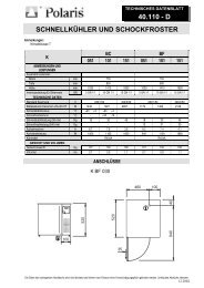
ABBATTITORE/CONGELATORE - BLAST CHILLER/SHOCK FREEZERSCHOCKKÜHLER/SCHOCKFROSTER - CELLULE DE REFROIDISSEMENT ET CONGELATION RAPIDEMODELLO - MODELMODELL - MODELECondensazione - CondensationKondensation - CondensationLxPxH - WxDxHBxTxH - BxDxHmm750x690x800BF051T760x700x850760x700x950Prestazioni - PerformanceLeistungen - Performancekgkg+70 +3 °C+70 -18 °C139Classe climatica - Climatic classificationKlimaklasse - Classe climatiqueCapacità di refrigerazioneRefrigeration capacityGefriervermögenPouvoir de refrigerationTipo refrigerante - RefrigerantKältemittels - GazPotenza - PowerLeistung - PuissanceWWW max 890 (**) 861 (**) 890 (**) 861 (**) 890 (**) 861 (**)W max 501 501 501 501 501 501T727727R404ACorrente assorb. - Absorb. CurrentStromaufnahme - Abs. CouratA max 4,86 4,67 4,86 4,67 4,86 4,67A max 2,17 2,17 2,17 2,17 2,17 2,17Sistema di refrigerazione - Refrigerating systemKühlsystem - Systéme de réfrigérationDotazione interna - Inside equipmentZubehör - Equipment interieurVENTILATO - VENTILATE - BELÜFTET - VENTILATE1 coppia supporti + 1 sonda al cuore1 pair of tray slides support + n. 1 core probe1 Paar Halterungen- und Auflageschienen + n.1 Kertemperaturfühler1 paire de échelles + n. 1 sonde au coeurPeso - WeightGewicht - Poidskgkg85601007510176Alimentazione - SupplyAnschlusswert - Alimentation( ** )Tevaporazione=-23,3°C Tcondensazione=+54,4°CEvap.temp.=-23,3°C Cond.temp=+54,4°CT.Verd.=-23,3°C T.Kond.=+54,4°CT.èvaporation=-23,3°C T.condensation=+54,4°CV/~/Hz230 / 1 / 50Refrigerato - Refrigerated - Gekühlt - RéfrigeréPredisposto - Remote unit - Für Zentralkühlung - Sans groupe05/03/0226
ABBATTITORE/CONGELATORE - BLAST CHILLER/SHOCK FREEZERSCHOCKKÜHLER/SCHOCKFROSTER - CELLULE DE REFROIDISSEMENT ET CONGELATION RAPIDEMODELLO - MODELMODELL - MODELELxPxH - WxDxHBxTxH - BxDxHmmBC051 BF051 BC101 BF101 BC151 BF151755x800x1030 755x800x1415 755x800x1800Prestazioni - PerformanceLeistungen - Performancekg+70 +3°C 18 18 30 30 46 46+70 -18°C - 12 - 21 - 30Classe climatica - Climatic classificationKlimaklasse - Classe climatiqueN N N N N NCapacità di refrigerazioneRefrigeration capacityGefriervermögenPouvoir de refrigerationTipo refrigerante - RefrigerantKältemittels - GazPotenza - PowerLeistung - PuissanceCorrente assorb. - Absorb. CurrentStromaufnahme - Abs. CouratW 2396 (*) 1129 (**) 3110 (*) 1480 (**) 4900 (*) 1886 (**)W 2396 (*) 1129 (**) 3110 (*) 1480 (**) 4900 (*) 1886 (**)R404AW max 1250(*) 1440 (**) 1550 (*) 1910 (**) 2390 (*) 2770W max 490 490 850 850 870 870A max 5,80 6,80 6,80 9,00 5,00 5,70A max 2,20 2,20 3,70 3,70 3,80 3,80Sistema di refrigerazione - Refrigerating systemKühlsystem - Systéme de réfrigérationDotazione interna - Inside equipmentZubehör - Equipment interieurVENTILATO - VENTILATE - BELÜFTET - VENTILATE1 coppia supporti + 1 sonda al cuore1 pair of tray slides support + n. 1 core probe1 Paar Halterungen- und Auflageschienen + n.1 Kertemperaturfühler1 paire de échelles + n. 1 sonde au coeurPeso - WeightGewicht - Poidskgkg157127185225165 200Alimentazione - SupplyAnschlusswert - AlimentationV/~/Hz230 / 1 / 50 380 / 3 / 50( * ) Tevaporazione=+7,2°C T.condensazione=+54,4°C ( ** ) Tevaporazione=-23,3°C Tcondensazione=+54,4°CEvap.temp.=+7,2°C Cond. Temp. =+54,4°CEvap.temp.=-23,3°C Cond.temp=+54,4°CT.Verd=+7,2°C T.Kond. =+54,4°CT.Verd.=-23,3°C T.Kond.=+54,4°CT èvaporation=+7,2°C T.condensation=+54,4°CT.èvaporation=-23,3°C T.condensation=+54,4°CRefrigerato - Refrigerated - Gekühlt - RéfrigeréPredisposto - Remote unit - Für Zentralkühlung - Sans groupe05/03/0227
SCHEMA ELETTRICOWIRING DIAGRAMSCHALTSCHEMASCHEMA ELECTRIQUELEDNINGSDIAGRAMELEKTRISCHE SCHEMA28711.180.0
SCHEMA ELETTRICOWIRING DIAGRAMSCHALTSCHEMASCHEMA ELECTRIQUELEDNINGSDIAGRAMELEKTRISCHE SCHEMA29711.179.0
SCHEMA ELETTRICOWIRING DIAGRAMSCHALTSCHEMABF051T COND/ARIASCHEMA ELECTRIQUELEDNINGSDIAGRAMELEKTRISCHE SCHEMA+70/-18°C230V-50Hz-1PhB1 B2 B3G2G119 20 21 22 44 45 23 24 25 26 27 28 - +1 2 3 4 5 6 7 8 9 10 31 32 33 11 14 13 15 46 47 48L338C11C114100M1 M2 M2R2MMM3R1MM M3 M1 ~ 1 ~1 ~1 ~1 ~N777 7777 7PE711.330.030
SCHEMA ELETTRICOWIRING DIAGRAMSCHALTSCHEMABF051T COND/H2OSCHEMA ELECTRIQUELEDNINGSDIAGRAMELEKTRISCHE SCHEMA+70/-18°C230V-50Hz-1PhB1 B2 B3G2G119 20 21 22 44 45 23 24 25 26 27 28 - +1 2 3 4 5 6 7 8 9 10 31 32 33 11 14 13 15 46 47 48L33P218C11C114100M1 M2 R2MM M3 M M3R1M1 ~1 ~1 ~1 ~N777 777 7PE711.331.031
SCHEMA ELETTRICOWIRING DIAGRAMSCHALTSCHEMABF051T PREDISPOSTOSCHEMA ELECTRIQUELEDNINGSDIAGRAMELEKTRISCHE SCHEMA+70/-18°C230V-50Hz-1PhB1 B2 B3G2G119 20 21 22 44 45 23 24 25 26 27 28 - +1 2 3 4 5 6 7 8 9 10 31 32 33 11 14 13 15 46 47 48L338C11C114100UMCR3M3M1 ~M3M1 ~R1R2N777 777 7PE711.332.032
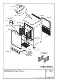
LEGENDAKEYB1 Sonda temperatura B1 Temperature probeB2 Sonda sbrinamento B2 Defrosting probeB3 Sonda al cuore B3 Core measuring probeC Condensatore elettrico C Electric condenserFU Fusibile FU F<strong>use</strong>G1 Schede potenza G1 Power cardsG2 Scheda com<strong>and</strong>o G2 Comm<strong>and</strong> cardI3 Micro porta I3 Door microswitchK1 Contattore copmpressore K1 Compressor contactorL Linea L LineL1 Linea 1 trifase L1 3-phase line #1L2 Linea 2 trifase L2 3-phase line #2L3 Linea 3 trifase L3 3-phase line #3M1 Motocompressore M1 CompressorM2 Motoventilatore condensatore M2 Fan of the condenserM3 Motoventilatore evaporatore M3 Fan of the evaporatorN Neutro N NeutralP Pressostato P Pressure switchPE Punto terra PE Earth pointQ1 Relè di potenza Q1 Power relayQ3 Relè protettore termico compressore Q3 Thermal protection relay for compressorR1 Resistenza cornici R1 Frames resistanceR2 Resistenza sbrinamento R2 Defrosting resistanceR3 Resistenza evaporatore R3 Evaporator resistanceR6 Resistenza scarico R6 Guard resistanceS Starter S StarterT2 Reattore T2 BallastW2 Lampada UVC W2 UVC lampX1 Morsettiera X1 Terminal boardZ Filtro antidisturbo Z Noise prevention filterUMC Unità motocondensante UMC Motorised condensing unit33
( I )( GB )DO163111MANUALE D'INSTALLAZIONEABBATTITORE/CONGELATORE(ELETTRONICO)INSTALLATION MANUALBLAST CHILLER/SHOCK FREEZER(ELECTRONICAL)
INDICECONTENTSCAP.1 INSTALLAZIONECHAP.1 INSTALLATION1.1 Trasporto del prodotto,movimentazione 1.1 Transporting <strong>and</strong> h<strong>and</strong>ling the product1.2 Descrizione delle operazioni di 1.2 Description of installation procedurespiazzamento1.3 Allacciamento 1.3 Connection1.3.1 Modelli BC/BF1, BC/BF2 1.3.1 Connection to el.mains modelsBC/BF1, BC/BF21.3.2 Modelli BC/BF3 1.3.2 Connection to el.mains modelsBC/BF31.4 Reinstallazione 1.4 Reinstallation1
1. INSTALLAZIONEQuesto capitolo contiene informazioni destinate a personale tecnico specializzato.1.1 TRASPORTO DEL PRODOTTO, MOVIMENTAZIONELe dimensioni dell'apparecchiatura sono contenute, ma non per questo può essere trasportata a mano.Il sistema di sollevamento da utilizzare è quello del carrello a forche o del transpallet, ponendo particolare cura albilanciamento del peso.Normalmente l'imballo è di cartone su pallet e per una maggiore sicurezza durante il trasporto e lo spostamento, ilpallet viene fissato tramite reggetta.Sull'imballo vengono stampati dei contrassegni di avvertimento, che rappresentano le prescrizioni che devonoessere osservate al fine di assicurare che nelle operazioni di carico e scarico, nel trasporto enell'immagazzinamento la merce non subisca avarie.CONTRASSEGNI STAMPATI SUI NOSTRI IMBALLI(UNI 6720-70):ALTO FRAGILE TENERE ALL'ASCIUTTOcaricare e scaricare con precauzionePer quanto riguarda lo smaltimento dell'imballo, esso può essere riutilizzato per un'eventuale reinstallazione.L'utilizzatore dovrà comunque comportarsi secondo le norme vigenti nel proprio paese.Limiti di impilabilitàSia per quanto riguarda il trasporto, sia per l'immagazzinamento degli abbattitori, il limite di impilabilità è massimo 2apparecchiature.A CAUSA DEL BARICENTRO NON COINCIDENTE CON IL CENTRO GEOMETRICODELL'APPARECCHIATURA,FARE ATTENZIONE ALL'INCLINAZIONE DURANTE GLI SPOSTAMENTI.1.2 DESCRIZIONI DELLE OPERAZIONI DI PIAZZAMENTOSi consiglia di sballare immediatamente l'apparecchiatura non appena ricevuto il collo, per poterne controllarel'integrità e l'assenza di danni al trasporto.Eventuali danni devono essere tempestivamente segnalati al vettore. In nessun caso comunque alcun apparecchiodanneggiato potrà essere reso al costruttore senza preavviso e senza averne ottenuta preventiva autorizzazionescritta.Come sballare l'apparecchiatura:- Rimuovere l'imballo in cartone, sfil<strong>and</strong>olo verso l'alto. Fare attenzione a non tagliare il cartone con lame taglientiche potrebbero rovinare l'acciaio;- Rimuovere le varie protezioni;- Con un carrello a forche, sollevare l'apparecchiatura e portarla sul luogo di installazione facendo attenzione cheil carico non sia sbilanciato.ATTENZIONE: DURANTE GLI SPOSTAMENTI NON SPINGERE O TRASCINARE L'APPARECCHIATURA PEREVITARE CHE SI RIBALTI O CREARE DANNI AD ALCUNE PARTI DELLO STESS(ADESEMPIO I PIEDINI). NON INCLINARE MAI L'APPARECCHIATURA DAL LATO PORTA.Dopo aver posizionato l'apparecchiatura togliere il basamento in legno.Procedere in questo modo:Con il carrello a forche tenerla sollevata di pochi centimetri.Con l'ausilio di scalpello e martello schiodare le tavole inferiori, facendo attenzione a non danneggiare i piedini.Rimettere a terra e schiodare il resto dei masselli in legno.Durante queste operazioni fare molta attenzione alle graffette che uniscono i masselli in legno, potrebberoprovocare ferite.Per ottenere il miglior rendimento dell'abbattitore e del congelatore si consiglia di collocarlo il più lontano possibileda fonti di calore, compresa l'esposizione a raggi solari diretti, ed in una posizione tale da garantire una buonacircolazione dell'aria in corrispondenza del cruscotto e della parte superiore asolata del piano.Livellare l'apparecchiatura avvit<strong>and</strong>o e svit<strong>and</strong>o i piedini. Prima del definitivo posizionamento, togliere il protettivo inPVC da tutte le pareti interne ed esterne del mobile.Per evacuare l’acqua di lavaggio collegare il tubo flessibile di scarico della cella ad uno scarico sifonato apavimento. Il tubo è fissato sul cielo del vano motore e vi si accede dallo schienale.2
ATTENZIONE: LA MACCHINA NON E' STATA PROGETTATA PER ESSERE INSTALLATA IN UNAATMOSFERA A RISCHIO DI ESPLOSIONE.1.3 ALLACCIAMENTO1.3.1 Modelli BC/BF051, BC/BF151, BF051T.Prima del collegamento alla rete di alimentazione elettrica, assicurarsi che la tensione e la frequenza di retecorrispondano a quelle riportate nella targhetta caratteristiche dell'apparecchiatura. E' ammessa una variazione +/-10% della tensione nominale.ATTENZIONE: NON IMPIEGARE PRESE O SPINE NON PROVVISTE DI TERRA.LA PRESA DI RETE DEVE ESSERE DA 16A/250 VOLT, PROVVISTA DI MESSA A TERRA.Al fine di salvaguardare l'apparecchiatura da eventuali sovraccarichi o cortocircuiti, il collegamento alla lineaelettrica va fatto tramite un interruttore magnetotermico differenziale ad alta sensibilità (30 mA) a ripristino<strong>manual</strong>e, di adeguata potenza.Per il dimensionamento del dispositivo di protezione, va tenuto conto della:Imax = 2,3 In (corrente nominale)Icc (corrente di corto circuito)= 4500A.1.3.2 Modelli BC/BF151.Prima del collegamento alla rete di alimentazione elettrica, assicurarsi che la tensione e la frequenza di rete sianopari a 400/3/50. E' ammessa una variazione in +/-10% della tensione nominale.COLLEGARE L'APPARECCHIATURA AD UN APPOSITO PUNTO PRESA CON INTERUTTOREQUADRIPOLARE CON PROTEZIONE TERMICA INCLUSA.Per il dimensionamento del dispositivo di protezione, va tenuto conto della:Imax = 2,3 In (corrente nominale)Icc (corrente di corto circuito) = 6000A.1.4 REINSTALLAZIONEPer una eventuale reinstallazione procedere in questo modo:1) Spegnere l'apparecchiatura agendo sul pannello com<strong>and</strong>i tasto off;2) Staccare la spina dalla presa di alimentazione e riavvolgere il cavo di alimentazione;3) Togliere tutti gli alimenti dall'interno della cella e pulire accuratamente la cella e gli accessori;4) Reimballare l'apparecchiatura avendo cura i rimettere le protezioni in polistirolo e fissare il basamento in legno.Tutto ciò per evitare danni durante il trasporto;5) Per il nuovo piazzamento ed allacciamenti, procedere come descritto precedentemente(DESCRIZIONE DELLE OPERAZIONI DI PIAZZAMENTO).3
1. INSTALLATIONThis section contains information intended for skilled technical staff.1.1 TRANSPORTING AND HANDLING THE PRODUCTThe appliance is of compact size, but this does not mean that it can be carried around by h<strong>and</strong>.It must be lifted using a fork-lift truck or pallet trolley, taking great care to balance the weight.The packaging normally consists of cardboard on a pallet, <strong>and</strong> for greater safety during transport <strong>and</strong> h<strong>and</strong>ling thepallet is secured to the bottom of the cabinet using brackets, or held in place with tapes.The warning symbols indicating the precautions which must be taken to prevent damage during loading <strong>and</strong>unloading, transport <strong>and</strong> storage are printed on the packagingSYMBOLS USED ON OUR PACKAGING (UNI 6720-70):THIS SIDE UP FRAGILE KEEP DRYload <strong>and</strong> unload with careThe packaging may be kept <strong>and</strong> <strong>use</strong>d again for any reinstallation.Users must always dispose of packaging materials in accordance with the regulations in force in their countries.Stacking limitsThe stacking limit during both transport <strong>and</strong> storage is 2 appliances.SINCE THE APPLIANCE'S CENTRE OF GRAVITY DOES NOT LIE IN ITS GEOMETRICAL CENTRE, TAKECARE THAT IT DOES NOT TIP WHEN HANDLING.1.2 INSTALLATION PROCEDURESUnpack the appliance immediately on receipt to check that no pieces have been lost or damaged in transit.Inform the carrier of any damage at once. No damaged appliances must be returned to the manufacturer withoutprior written authorization.Unpack the appliance- Remove the cardboard packaging by lifting it away. Never cut the board with sharp blades which mightdamage the steel.- Remove the various protective materials..- Using a fork-lift truck, lift the appliance <strong>and</strong> take it to the place of installation, ensuring that the load is wellbalanced.CAUTION: WHEN HANDLING, NEVER DRAG THE APPLIANCE OR PUSH IT TOO HARD AS IT MIGHT TIPUP, OR SOME PARTS (SUCH AS THE FEET) MIGHT BE DAMAGED.NEVER TILT THE APPLIANCE AWAY FROM THE DOOR SIDE.After positioning the appliance, remove the wooden base.Proceed as follows:Hold the appliance a few centimetres above the floor using a fork-lift truck.Remove the boards underneath with a hammer ahd chisel, taking care not to damage the feet.Return to the ground <strong>and</strong> remove the remaining blocks of wood.During these operations, remember that the wooden staples which hold the blocks of wood together are sharp <strong>and</strong>may ca<strong>use</strong> injury.In ordere to obtain better performances of the <strong>blast</strong> <strong>chiller</strong> <strong>and</strong> of the <strong>shock</strong> <strong>freezer</strong>, we reccomend you install themas far away from heat sources as possible, including any exposure to direct sunlight. They should also bepositioned in a way that some good air circulation is ensured on the instrument board <strong>and</strong> on the upper slottedportion of the top.Level the equipment by screwing the feet either in or out.Before definitely positioning the equipment, remove the PVC protection film from all its internal <strong>and</strong> external walls.With an adequate pipe, connect the discharge coupling of the cell with a floor-trapped discharge.The coupling is on the top wall inside the motor compartment, <strong>and</strong> access to it is possible from the back panel.BEWARE: THE EQUIPMENT HAS NOT BEEN CONCEIVED TO BE PLACED IN AN ENVIROMENT WITHEXPLOSION HAZARDS.4
1.3 CONNECTION1.3.1 CONNECTION TO EL.MAINS MODELS BC/BF051, BC/BF101, BF051TBefore making the connection to the mains, ensure that the voltage <strong>and</strong> frequency are as indicated on theappliance nameplate. A variation of +/-10% on the rated voltage is permitted.CAUTION: NEVER USE SOCKETS OR PLUGS WITHOUT EARTH CONNECTION THE MAINS SOCKET(16A/250 VOLTS) MUST HAVE AN EARTH CONNECTION.To protect the appliance against overloads or short-circuits, it must be connected to the mains by meansof a suitably rated high sensitivity (30 mA) differential security breaker with <strong>manual</strong> reset.When calculating the rating of this protective device, consider that:Imax = 2,3 In (rated current)Icc (short-circuit current)= 4500A.1.3.2 CONNECTION TO EL.MAINS MODELS BC/BF151Before connection to mains make sure that voltage <strong>and</strong> frequency of mains equal 400/3/50.A tollerance of +/- 10% is admissible.CONNECT THE APPLIANCE TO AN OUTLET WITH A FOUR-POLE SWITCH AND INTEGRAL THERMALOVERLOAD CUT-OUT.When calculating the rating of this protective device, consider that:Imax = 2,3 In (rated current)Icc (short-circuit current) = 6000A.1.4 REINSTALLATIONIn case of reinstallation, proceed as follows:1) Switch off the mains switch;2) Disconnect the plug from the power supply socket <strong>and</strong> rewind the cable;3) Remove all foods from the refrigerator <strong>and</strong> clean the inside <strong>and</strong> the accessories thoroughly;4) Repackage the appliance, taking care to fit the polystyrene guards in their original positions <strong>and</strong> secure thewooden base, to prevent damage in transit;5) For the new positioning <strong>and</strong> connections, proceed as previously described (INSTALLATION PROCEDURES).5