User Manual - Polaris S.p.A.
User Manual - Polaris S.p.A.
User Manual - Polaris S.p.A.

You also want an ePaper? Increase the reach of your titles
YUMPU automatically turns print PDFs into web optimized ePapers that Google loves.
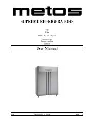
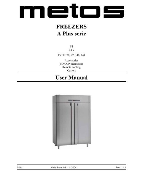
FREEZERSA Plus serieBTBTVTYPE: 70, 72, 140, 144AccessoriesHACCP thermostatRemote coolingCasters<strong>User</strong> <strong>Manual</strong>S/N: Valid from: 04. 11. 2004 Rev.: 1.1
4.11.2004 Rev. 1.1Dear Customer,Congratulations on deciding to choose a Metos appliance for your kitchen activities. Youmade an excellent choice. We will do our best to make you a satisfied Metos customerlike thousands of customers we have around the world.Please read this manual carefully. You will learn correct, safe and efficient working methodsin order to get the best possible benefit from the appliance. The instructions and hintsin this manual will give you a quick and easy start, and you will soon note how nice it isto use the Metos equipment.All rights are reserved for technical changes.You will find the main technical data on the rating plate fixed to the equipment. When youneed service or technical help, please let us know the serial number shown on the ratingplate. This will make it easier to provide you with correct service.For your convenience, space is provided below for you to record your local Metos servicecontact information.METOS TEAMMetos service phone number:...............................................................................................Contact person:....................................................................................................................
4.11.2004 Rev. 1.1
4.11.2004 Rev.1. General information ..................................................................................... 11.1 Symbols used in the manual .......................................................................................... 11.2 Symbols used on the appliance ...................................................................................... 11.3 Checking correspondence between the appliance and the manual ............................... 22. Safety .............................................................................................................. 32.1 Using the appliance safely ............................................................................................. 32.2 Recommendations on how to best operate the appliance (2000/40/EC) ....................... 32.2.1 Installation tips ....................................................................................................... 42.3 Disposing of the appliance (environmental protection) ............................................... 43. Functional description .................................................................................. 53.1 Intended use .................................................................................................................. 53.2 Control panel ................................................................................................................. 64. Operating instructions ................................................................................. 74.1 Prior to use .................................................................................................................... 74.1.1 Preliminary checks ................................................................................................. 74.1.2 Start-up and checks ............................................................................................... 74.2 Operation ....................................................................................................................... 84.3 After-use care ............................................................................................................... 84.3.1 Cleaning ................................................................................................................. 84.3.2 Maintenance operations that may be carried out by the user ................................ 84.3.3 Maintenance operations to be performed by authorised technical support personnel94.3.4 Rating plate data .................................................................................................... 94.3.5 Idle periods .......................................................................................................... 105. Installation ................................................................................................... 115.1 General information ..................................................................................................... 115.2 Transport and storage .................................................................................................. 115.3 Unpacking the appliance ............................................................................................. 125.4 Installation ................................................................................................................... 125.4.1 Cleaning ............................................................................................................... 125.5 Electrical connections .................................................................................................. 125.6 First turn-on ................................................................................................................ 125.7 Connections for “Remote cooling” ............................................................................. 135.7.1 Electrical connections .......................................................................................... 135.7.2 Connecting refrigerant pipes ................................................................................ 13
4.11.2004 Rev.5.7.3 Suggestions .......................................................................................................... 136. Adjustment instructions ............................................................................. 146.1 Thermostat operation ................................................................................................... 146.1.1 Keyboard .............................................................................................................. 146.1.2 Display ................................................................................................................. 146.1.3 Setting the SETPOINT ........................................................................................ 156.1.4 Starting a manual defrost ..................................................................................... 156.2 HACCP Thermostat operation (additional) ................................................................. 166.2.1 General information ............................................................................................. 166.2.2 Keyboard .............................................................................................................. 166.2.3 Display ................................................................................................................. 176.2.4 Setting up the clock ............................................................................................. 186.2.5 Setting the SETPOINT ........................................................................................ 196.2.6 Starting a manual defrost ..................................................................................... 196.2.7 Clearing the power failure alarm. ....................................................................... 196.2.8 HACCP functions ................................................................................................ 196.2.9 Alarm list - HACCP menu ................................................................................... 206.2.10 Function menu ................................................................................................... 206.3 Changing the light bulb ............................................................................................... 226.4 Attaching and detaching the grille support guide ........................................................ 227. Troubleshooting .......................................................................................... 238. Spare parts .................................................................................................. 258.1 Voltage codes .............................................................................................................. 278.2 Product codes ............................................................................................................... 279. Technical specifications .............................................................................. 37
General information4.11.2004 Rev. 1.11. General informationThis manual contains information on how to minimise environmental impact in compliancewith ECO-LABEL regulations (2000/40/EC).Read the instructions in this manual carefully, as they contain important information onhow to install, use and service the appliance safely, properly, and effectively.Keep this manual in a safe place for future reference by other users.This appliance should be installed following the instructions provided by the manufacturerand in compliance with all applicable local regulations. This appliance should be connectedto the power and water supply only by qualified personnel.All personnel in charge of using this appliance should be specifically trained in its operation.In the event of failure or malfunction, switch off the appliance. The periodic functionalchecks requested in this manual should be carried out according to the instructions. Havethe appliance serviced by a technically qualified person duly authorized by the manufacturerthat uses genuine spare parts. Never attempt to repair this appliance by yourself. Repairscarried out by unqualified people can cause damage.Failure to comply with the above may jeopardise the appliance’s safety.1.1 Symbols used in the manualThis symbol informs about a situation where a safety risk could be imminent. The instructionsprovided must be followed in order to prevent injury.This symbol informs about the right way to act in order to prevent bad results, damage tothe appliance, or hazardous situations.This symbol informs about tips and tricks that help the user to get the best possible performanceout of the appliance.This symbol informs about a function that needs to be taken into account when doing selfcontrol.1.2 Symbols used on the applianceThis symbol on a part warns the user that there are electrical terminals behind it. Therefore,the concerned part should only be removed by qualified personnel.1
General information4.11.2004 Rev. 1.11.3 Checking correspondence between the appliance and the manualThe rating plate of the appliance shows its serial number. If the manuals are missing, youmay order new ones from the manufacturer or your local representative. When orderingnew manuals it is essential to quote the serial number shown on the rating plate.Keep this manual as well as the wiring diagram with care, and put them at the operator’sdisposal for future reference.2
Safety4.11.2004 Rev. 1.12. Safety2.1 Using the appliance safelyRead the following directions and warnings carefully:2.2 Recommendations on how to best operate the appliance (2000/40/EC)Following the suggestions contained in this chapter will result in lower energy consumption.These appliances are designed for indoor use.Choosing a convenient installation location for the appliance is extremely important to ensureproper operation and energy savings; in fact, users who have the possibility of installingthe appliance in a non-heated or less-heated room can achieve significant energysavings.The best performance is obtained when room temperature ranges between +18°C (64°F)and +43°C (109°F) (Climate class T); +18°C (64°F) and +38°C (100°F) (Climate classST); +16°C (61°F) and +32°C (90°F) (Climate class ST); the rating plate found inside theappliance shows the climate class to which it belongs.If room temperature exceeds the values indicated by the climate class of this product,please follow the directions below: when room temperature falls below the minimum value,a proper storage temperature in the freezer compartment may not be ensured; therefore,we recommend that you use up all food contained in it as soon as possible.In order to achieve additional energy savings and ensure proper operation, we recommendthat you avoid opening the door/lid or holding it open more often or longer than necessary.It is important to let foods cool down prior to storing them in the appliance, because otherwisethey will produce steam which, in turn, favours frost build-up on the evaporator;in addition, it is important that the cool-down period is as short as possible (if possible,use blast chillers) for health and hygiene reasons.Avoid heavy frost build-up on the evaporator; if necessary, carry out additional manualdefrost cycles to melt away any frost build-up.Replace the door gasket if it is not working properly.It is useful to keep the condenser found in the appliance’s motor compartment and thespace under the refrigerator clean by removing any dust and cooking vapours.3
Safety4.11.2004 Rev. 1.12.2.1 Installation tipsCheck that the surface on which the appliance will rest is level and suitable to support itsweight.To ensure proper airflow and avoid any damage to the refrigeration circuit, allow a minimumside clearance of 50 mm (2 inches); do not place the appliance close to heat sources(such as ovens, radiators, etc.) or exposed to direct sunlight and provide suitable insulationfrom walls or floor if they transmit heat.If the appliance has been moved, wait for a while before switching it on again.2.3 Disposing of the appliance (environmental protection)Our appliances contain the refrigerant shown on the corresponding rating plate as perRegulation (EC) No. 2037/2000 of 29 June 2000; in addition, the appliance is composedof reusable or recyclable parts and materials. Therefore, at the end of its lifetime, the applianceshould be delivered to a specific disposal centre. The best method to ensure thatno one will remain trapped inside is to take off the door completely.The appliance must not be disposed of together with household waste and metal scrap.Absolutely avoid damaging the refrigeration circuit, particularly near the heat exchanger.Pic. 2.34
Functional description4.11.2004 Rev. 1.13. Functional description3.1 Intended useThis appliance should only be used to store food and beverages. The manufacturer shallnot be held liable for the consequences resulting from unintended uses of this appliance.Do not store food in direct contact with the structure.Both the appliance’s construction features and the condensing unit’s capacity have beendesigned to store only pre-cooled products. Never place carbonated beverages into thelow-temperature compartment as they may explode. Never place liquids or hot food intothe appliance and do not fill lidded containers to the top.In all appliances there are surfaces subject to frosting. Depending on the model, frost maybe melted away either automatically (automatic defrost) or manually. Never attempt to removefrost using a pointed object because in this way you could irreparably damage theappliance.Do not use any mechanical device or other artificial means to accelerate the defrost process.The Manufacturer declines all responsibility, and the warranty shall be null and void, ifelectrical and/or mechanical alterations are made to the product.The warranty shall also be null and void if the product is tampered with or, in general, incase of alterations not expressly authorised and not made in compliance with the instructionsgiven herein.5
Functional description4.11.2004 Rev. 1.13.2 Control panelThe following components are found on the appliance’s front panel:Pic. 3.2 - Front Panel1. Main switch2. Light switch, for glass door cabinets only3. Temperature display / Electronic controller6
Operating instructions4.11.2004 Rev. 1.14. Operating instructions4.1 Prior to use4.1.1 Preliminary checksGeneral checksTo ensure proper operation:• Check that the appliance is well levelled. If necessary, adjust the mobile part of theadjustable feet until the appliance is perfectly level.• Check that all plastic protective film has been removed from outer surfaces.• Check that the inside has been cleaned with warm water and neutral soap.• Check that the appliance is positioned as far from heat sources as possible.• Check for free, unobstructed air circulation inside motor compartment.• Check that locking keys (if available) are out of children’s reach.Checking the electrical equipment• Check that the power network voltage and frequency rating matches the valuesshown on the appliance’s rating plate (item 6 in paragraph "Rating plate data").• Check that the screws fixing the wires to the electric components found in theboard are properly tightened (as vibration could have worked them loose duringhandling and transportation).• Make sure that a 16A-fuse has been fitted upstream of the power socket (outlet).• Turn OFF the general switch to which the power cord plug will be connected.• Check that the power socket (outlet) is compatible with the type of plug the appliancehas. If necessary, have the plug replaced with a suitable one by a professionally qualifiedtechnician, who will be in charge of checking that the gauge of socket (outlet) wires issuitable for the appliance’s power input. Check that the plug is correctly plugged in.4.1.2 Start-up and checksOnce you have carried out all the above steps carefully, you are ready to start up the appliance:• Turn ON the general switch to which the power supply cord plug is connected.• Turn ON the appliance’s switch.• To change the SETPOINT, refer to paragraph "Thermostat operation" in chapter"Adjustment instructions".7
Operating instructions4.11.2004 Rev. 1.14.2 Operation4.3 After-use careProper storage of foodstuffs is a relevant factor in the safe and sanitary production of food;in addition, it improves the efficiency of foodservice activities and positively affects energyconsumption. Follow the directions below to obtain the highest performance possibleout of your appliance.Products should be placed into the appliance in such a way as to allow unobstructed airflow.Always leave some free space between the products and prevent them from comingin contact with the walls. If needed, adjust the distance between shelves. Products shouldalways be stored on the shelves; do not place any products on the cabinet’s bottom.4.3.1 CleaningHow often you will need to clean the appliance depends largely on how often you use it.Analyze the use and schedule the required cleaning operations.To clean the appliance’s inside and outside, use a neutral or slightly alkaline detergent.We recommend that you clean the inside with a disinfectant every once in a while. Impuritiesmay be removed using a damp cloth. Removing the shelves makes cleaning the insideeasier.Prevent water from coming in contact with the electrical components. Using a pressurisedjet of water to clean the appliance is forbidden. Never use metal objects to clean the appliance,as they could damage it.4.3.2 Maintenance operations that may be carried out by the userUnder normal conditions of use the appliance only requires a minimum of maintenance.The user can carry out the following operations:• Cleaning the inside and outside every day or as often as needed.• Cleaning the condenser at least twice a year or more often if used in a dusty environment.Before cleaning the condenser, turn the appliance off using the mainswitch and disconnect the power cord from the power socket (outlet). Use a vacuumcleaner or a soft brush. When brushing the condenser, exercise great care so asto avoid damaging the aluminium grid.• Check that the condensate drain hose is not clogged. If needed, clean it. Possiblemalfunctions due to a clogged drain may not be attributed to the manufacturer.• Check that the fan is properly fixed to its frame.• Check for fan unbalancing, evidenced by abnormal vibration or noise, thoroughly.• Check the power cord connecting the appliance to the wall socket (outlet) for cuts,cracks, or alterations which might compromise its insulation. If the power cordneeds servicing, contact your nearest technical support centre.8
Operating instructions4.11.2004 Rev. 1.14.3.3 Maintenance operations to be performed by authorised technical support personnelAny maintenance operations not mentioned in the above paragraphs, should be performedby authorised technical support personnel only. The need to perform maintenance operationsdepends largely on the external conditions and how often the appliance is used.For further information, contact your local representative. Identifying the appliance correctlyis useful when ordering spare parts or requesting maintenance or repair operations.The appliance’s model and serial number are shown on the rating plate found inside theappliance.4.3.4 Rating plate dataPic. 4.3.4 - Rating plate1. Serial Number2. Code3. Model4. Voltage5. Net capacity6. Power7. Defrost heater8. Power input9. Refrigerant10. Lowest and highest pressure11. Lamp12. Climate class13. Gas for expansion14. Year of Manufacture9
Operating instructions4.11.2004 Rev. 1.14.3.5 Idle periodsFollow the precautions below if the appliance will be left idle for some time:• Unplug the appliance from the wall socket (outlet);• Remove all foodstuffs from the appliance;• Defrost it and clean the inside;• Leave the door partly open to favour air circulation inside the cabinet and preventunpleasant smells from forming.• Store the appliance in such a way as to avoid that anyone can remain trapped inside.10
Installation4.11.2004 Rev. 1.15. Installation5.1 General information5.2 Transport and storageEnsure that installation is performed according to the instructions given under chapter"Recommendations on how to best operate the appliance (2000/40/EC)", "Installationtips". We remind you that insufficient airflow will certainly result in appliance malfunctionor damage.Once the appliance has been installed, ensure that it is not resting on the power cord.In the event of damage, the power cord should only be replaced by qualified personnelwith a special cable or cable assembly available from the manufacturer.Ensure compliance with all local safety rules in force at the time of installation.Prior to plugging in the appliance, ensure that the power distribution network ratingsmatch the values shown on the appliance’s rating plate.It is absolutely necessary that the appliance be connected to an effective earth (ground)connection. To this end, the power cord plug is equipped with a grounding contact. If thepower socket (outlet) of the system is not grounded (earthed), connect the appliance to aseparate grounding (earthing) system in compliance with applicable regulations in force.Ask for a qualified technician’s advice.The manufacturer declines all responsibility in case of non-compliance with this accidentpreventionrule.You must always be able to disconnect the appliance from power supply; therefore, oncethe appliance has been installed the power socket (outlet) should be easily accessible.If possible, do not unpack the appliance until it is placed near the final installation site. Donot tip it over.If the appliance has been tipped over, wait for a while until oil settles down again.The appliance should always be stored in sheltered areas.If the appliance was stored in a cold place, thus causing the temperature of the refrigerationunit to fall below 0°C (32°F), prior to start using the appliance keep it at room temperaturefor at least one hour so that the refrigeration unit will warm up to +16°C (61°F).Turning on the appliance when temperature is excessively low may result in compressormalfunction.11
Installation4.11.2004 Rev. 1.15.3 Unpacking the appliance5.4 InstallationUnpack the appliance and check for transport damage. Remove the protective film fromthe appliance’s body.Packing materials (plastic bags, polystyrene foam, nails, etc.) should be kept out of children’sreach as they are potential sources of hazard, and they should be properly recycledin compliance with local regulations in force.Place the appliance in its final installation site.When lifting the appliance with a suitable mechanical device, ensure that the structure atthe base is undamaged.Level the appliance using its adjustable feet. Use a level, if needed. The maximum permissibledeviation from the horizontal plane is +/-0.5 degrees. All four feet should be restingon the floor. This will ensure proper door operation.5.4.1 Cleaning5.5 Electrical connectionsPrior to use, clean the inside, the shelves and the outside with a cloth and wipe dry. Toclean use a neutral or slightly alkaline detergent.5.6 First turn-onThe appliance may be switched on three hours after installation. Plug the appliance into agrounded outlet (earthed socket). To do so, you will need to have a power outlet (socket)with a built-in 16A-fuse fitted upstream of the system. Check that power supply voltagematches the value shown on the appliance’s rating plate.Check that a circuit breaker switch having a contact gap of at least 3 mm is fitted upstreamof the power socket (outlet).Turn on the appliance using the main switch. After 1 minute, the compressor will start cyclinguntil internal temperature reaches the factory-set value. Do not load the applianceuntil the set temperature value has been reached. If you need to change any factory-set parameters,please read the instructions given under chapter "Adjustment instructions".12
Installation4.11.2004 Rev. 1.15.7 Connections for “Remote cooling”5.7.1 Electrical connectionsThe version with a control panel incorporates an electronic thermostat, switches, warninglights and indicators according to what has been specified under the chapter 3.2 “Construction”section. In this case the unit must be connected to a motor-driven condensingunit.Connect to terminals M on the compressor and on the electric condenser fan.5.7.2 Connecting refrigerant pipesSuction pipesLay down the suction line according to the established layout making sure that the numberof elbows and vertical sections where the refrigerant flows upward is limited to the veryminimum. Weld the suction line to the appliance exits jutting out of the side, provided forthis purpose. The suction pipe is generally to be distinguished from the liquid line by itsdiameter: it is the larger of them. Repeat the operation on the condensing unit. The verticalsections of the suction pipe shall be equipped with a trap and counter- trap to make oiltrapping easier and prevent it from flowing back to the evaporator when the compressoris off due to the thermostatic control.Please bear in mind that the only method applicable to vertical pipe sections where therefrigerant flows upward to make sure the oil returns to the compressor and prevent iffrom seizing due to insufficient lubrication, consists in “pulling” the oil by exploiting gasspeed.Liquid lineLay the liquid line pipes according to the established layout making sure that the numberof elbows and vertical sections where the refrigerant flows upward is limited to the veryminimum. Braze the liquid line pipe to the appliance outlet pipe located where the especiallyprovided protruding section is. The liquid line pipe can generally be distinguishedfrom the suction pipe by its diameter: it is the smaller one. Repeat the operation for thecondensing unit.5.7.3 Suggestions• SLANT: the horizontal sections of the suction pipes shall have a 0.5% slant towardsthe compressor to ensure oil back flow.• ELBOWS: to reduce pressure drops to a minimum, include as few elbows in yourline as possible and if you do, use large radius elbows only.• THERMAL INSULATION: the liquid line shall be insulated if exposed to the sunor if passing through areas where temperature is higher than condenser outlet temperatur13
Adjustment instructions4.11.2004 Rev. 1.16. Adjustment instructions6.1 Thermostat operation6.1.1 KeyboardPic. 6.1.1 - Thermostat ID 974 (BT, BTV)Arrow UP key (P1): Scrolls through the menu items; increases values, starts manual defrost.Arrow DOWN key (P2): Scrolls through the menu items; decreases values.FNC (P3): Exit function.SET (P4): Accesses the setpoint; accesses the menus; confirms commands.6.1.2 DisplaySymbols on the front panelLED L1 signals an alarm; blinking means that the alarm is in silent mode.LED L2 indicates that a defrost cycle is in progress; blinking means that a manual defrostcycle is in progress.LED L3 indicates that the compressor is on; blinking means that a delay time, a safety delaytime or a compressor shutdown is in progress.LED L4 (ID 974 only) indicates that the fan is on.14
Adjustment instructions4.11.2004 Rev. 1.16.1.3 Setting the SETPOINT1. To access the "Machine status" menu, press and immediately release the SET key.The label of the "Set" folder will appear;2. To display it, press SET again. The SETPOINT value will appear on the display.3. To change the SETPOINT value, use the arrow up and down keys within 15 seconds.6.1.4 Starting a manual defrostTo start a manual defrost cycle, press and hold down the arrow up key (P1) for 5 seconds.If the conditions required to start a defrost are not met (for example, evaporator sensortemperature is higher than defrost end temperature), the display will blink three times towarn the user that the operation will not be carried out.15
Adjustment instructions4.11.2004 Rev. 1.16.2 HACCP Thermostat operation (additional)The microprocessor-based control unit contains a series of parameters to control all cabinet’sfunctions. Each refrigeration unit has been pre-programmed at the factory. The usercan carry out two programming functions: setting temperature and starting a manual defrostcycle.6.2.1 General informationThe HAC series has been designed to meet the needs associated with the world of HAC-CP. The devices can record up to 20 alarm conditions taking place during the normal operationof the system or the cold rooms.The alarm conditions are conveniently shown on the display.The built-in clock allows recording the time at which the alarms took place and can alsobe used to schedule defrost cycles. For energy savings purposes, a "Night and Day" functionwith two different setpoints, is available.6.2.2 KeyboardPic. 6.2.2 - Thermostat HAC974SET (P1): Displays or changes the setpoint. While in programming mode, selects a parameteror confirms a value.M (P2): To access the menu. Press it and hold it down for 3 seconds to access the clockmenu.Arrow DOWN key (P3): To access the HACCP menu. While in programming mode, itscrolls the parameter codes or decreases their value.Arrow UP key (P4): To access the HACCP menu. While in programming mode, it scrollsthe parameter codes or increases their value. Press it and hold it down for 3 seconds tostart a manual defrost cycle.16
Adjustment instructions4.11.2004 Rev. 1.1Key combinationsArrow up key (P4) + arrow down key (P3): to lock or unlock the keypad.SET (P1) + arrow down key (P3): to access programming mode.SET (P1) + arrow up key (P4): to exit programming mode.6.2.3 DisplaySymbols on the front panelPic. 6.2.3.1LED L1: when lit, indicates that the compressor is on; blinking, indicates that the deviceis in programming mode (in this case, the LED L2 will blink as well) or a compressorshort-cycle protection delay is in progress.LED L2: when lit, indicates that a defrost cycle is in progress; blinking, indicates that adrip time or a defrost start delay is in progress.17
Adjustment instructions4.11.2004 Rev. 1.1Icons on the displayPic. 6.2.3.21. Degrees Celsius;2. Degrees Fahrenheit;3. High temperature alarm4. Low temperature alarm5. Critical temperature (high or low)6. Digital input alarm;7. Alarm list;8. Clock symbol:9. Date symbol:10. IR data transmission in progress;11. Indicates access to the "Function menu";12. Start time;13. End time.6.2.4 Setting up the clockIf "rtC" and the temperature alternate on the upper display when energising the device, itmeans that the clock needs to be set.To set the clock, proceed as follows:1. Press any key; the writing "Hur" will appear immediately on the lower display, andthe stored time on the upper one;2. Press the SET (P1) key; the hour digits will start blinking;3. Set the hour using the arrow keys (P3 and P4);4. Press SET to confirm the hour; the controller will display the next parameter;5. Repeat steps 2, 3 and 4 to set the remaining parameters of the clock: - Min: minutes(0÷60); - UdA: day of the week (Sun=Sunday, Mon= Monday; tuE = Tuesday,UEd = Wednesday, tHu = Thursday, Fri = Friday, SAt = Saturday; - dAy: day ofthe month (0÷31); - Mon: month (1÷12); - yEA: year (00÷99); - Hd1, Hd2, Hd3:days to which the non-working defrost schedule should be applied. (nu, Sun, Mon,tuE, UEd, tHu, Fri, SAt).18
Adjustment instructions4.11.2004 Rev. 1.16.2.5 Setting the SETPOINT1. Press and hold down the SET key for at least 2 seconds;2. The SETPOINT will blink on the display;3. To change the value, use the arrow keys.4. To store the new SETPOINT value press SET, or wait for 15 seconds to exit programmingmode.6.2.6 Starting a manual defrost1. Press and hold down the arrow up key for over 2 seconds.6.2.7 Clearing the power failure alarm.If the device’s built-in clock is working and the power failure alarm is enabled (par.bLE=yES), the message PUSH SET will be displayed on start-up every time the temperatureexceeds the temperature alarm threshold (par. HIt in the Menu)To clear the power failure alarm, proceed as follows:1. Press the SET (P1) key; this causes the alarm temperature override at start-up time(par. dAo) to start and the power failure event is not recorded.6.2.8 HACCP functionsThe HACCP alarms are:• High temperature alarm;• Low temperature alarm;• Power failure alarm.The following data are stored for each temperature alarm:• Start time (DATE and TIME);• End time (DATE and TIME);• Critical high or low temperature reached during the alarm condition;• Time at which a critical temperature was reached (DATE and TIME).Power failure alarmThe power failure alarm will be managed only if when power was restored, the clock wasstill working. In addition, the power failure alarm will be signalled only if temperature exceedsthe alarm threshold when the device is switched back on.• Power failure time (DATE and TIME);• Power restoration time (DATE and TIME);• Highest temperature reached.19
Adjustment instructions4.11.2004 Rev. 1.16.2.9 Alarm list - HACCP menuHow to display the alarms1. Press the arrow up key;2. The most recent alarm with the corresponding number will appear on the upperdisplay, and the alarm type on the lower display, according to the following codes:- HIt: high temperature alarm; - Lot: low temperature alarm; - blou: power failurealarm; - GEAL: generic digital input alarm.3. Press the arrow up key again to display the codes of the remaining alarms, fromthe oldest to the most recent.4. To find out when an alarm occurred, how long it lasted and what was the highesttemperature reached, press SET;5. The display will alternately show the time and date when the alarm started; at thesame time, the clock, calendar, and message "from" icons will light up.6. By pressing the arrow up key again, the display will alternately show the time anddate when the alarm ended in the "message to" field.7. By pressing the arrow up key again, the critical temperature reached together withthe time and date when it was reached, will be displayed. The alarm and criticaltemperature symbols will blink.8. Press the M key to exit.6.2.10 Function menuThe Function menu contains all the main controller variables. While in the Functionmenu, the "menu" message remains lit.• rSt: erases all stored alarms. It can be PASSWORD-PROTECTED. The time anddate of the last time the alarms were cancelled will alternately appear on the lowerdisplay. When the device is first installed, the display will show zeros;• LOt: low temperature alarm threshold. It can be PASSWORD-PROTECTED.• HIt: high temperature alarm threshold. It can be PASSWORD-PROTECTED.• ir: IR command;• PASS: enables, changes or disables the PASSWORD.Accessing the function menuPress and release key M.Exiting the function menuPress and release M or wait for the time-out to elapse (15 seconds).Entering the password1. All functions contained in the Function Menu can be password-protected.2. If a password is required, the lower display will show the writing "PASS" whilethe upper display will show three blinking zeros "000".3. Press the arrow up key to enter the right number;20
Adjustment instructions4.11.2004 Rev. 1.14. Then press SET to confirm;5. If the password is right, the function will be enabled, otherwise you will need tostart all over from step 2.NOTE: to disable the password, just set it to zero.Function rSt: erasing all stored alarms.1. Access the Function menu;2. Choose the "rSt" function and then press SET;3. Enter the password, if required; otherwise, all alarms will be erased immediately.4. The controller will return to temperature display mode.Functions HIt and LOt: high and low temperature alarms1. Access the Function menu;2. Choose the function "LOt" or HIt", then press SET to enable it;3. Enter the PASSWORD, if required;4. Now, press the arrow up and down keys to change the temperature or press SET toconfirm the value entered;5. The next function will be displayed.Function PASS: password changeTo change the password, you will need to enter the old password first and then set the newone.1. Access the Function menu;2. Choose the "PASS" - "oLd" function and then press SET;3. The lower display will show the writing "PASS" while the upper display will showthree blinking zeros "000".4. Enter the current PASSWORD and press SET to confirm;5. The lower display will show the writing "PASS" while the upper display will show"nEU" blinking;6. Press SET and enter the new PASSWORD with the help of the arrow up and downkeys;7. Press SET to confirm and got to the next function.Function ir: IR data transmissionTo download all the alarms stored in the controller’s memory to the portable HAC-IR device,proceed as follows:1. Access the Function menu.2. Choose the "ir" function and then press SET. The controller will return to temperaturedisplay mode and the symbol number 10 (*** 'Pic. 6.2.3.2' on page 18 ***)will light up.3. Press the reception button on the HAC-IR and move it close to the controller.21
Adjustment instructions4.11.2004 Rev. 1.16.3 Changing the light bulbTo change the light bulb perform the following steps (the voltage of the light bulb isshown on the adhesive label):• Switch off the appliance and disconnect the power cord;• Open the appliance door;• Remove the protective glass shield from the light;• Unscrew the light bulb located in the instrument panel and replace it with an identicalcomponent of the same voltage;• Refit the glass shield.6.4 Attaching and detaching the grille support guideCarry out the following steps to attach the grille support guides correctly:Push the guide downwards (2) and then inwards (3) in the chosen position of the rack.Pic. 6.4Perform the operation in reverse order to detach the guide.22
Troubleshooting4.11.2004 Rev. 1.17. TroubleshootingIn the event of malfunction, check the list below to see if it is possible to restore the applianceto working condition without needing to call the technical support service. Forfurther information, please contact your nearest technical support centre.TROUBLE POSSIBLE CAUSE REMEDYSENSOR(S) FAILURECOMPRESSOR WILLNOT RESTARTCOMPRESSOR SEL-DOM STOPSFROSTED COMPRES-SOR SHELLNOISY APPLIANCEOVERFLOWING OFSELF-EVAPORATINGCONDENSATE TRAYSensor disconnectedSensor damagedElectrical equipment of the compressor(relay, motor protection and condenser) isfaulty.Compressor has a winding open or shorted,or there is an earth (ground) faultRoom temperature is too highRefrigerated cabinet condenser is dirtyLow refrigerant chargeDoor gaskets do not ensure proper sealFrost build-up on the evaporatorExcess refrigerant chargeFrost build-up on the evaporatorEvaporator motor fan(s) damagedLoose screwsVibrating pipesHot or high-water content foodstuffs arebeing introduced into the appliance too oftenDoors and/or drawers are opened too oftenConnect sensor to the thermostat againCall an authorised technical support centre tohave it replacedCall an authorised technical support centre tohave the concerned component replacedCall an authorised technical support centre tohave the compressor replacedEnsure proper ventilation to the roomCheck it on a regular basis and clean it thoroughlyCall an authorised technical support centre tofind and repair any leaks and to recharge thecompressor with refrigerant.Call an authorised technical support centre toperform the necessary replacementDo not place hot or high water content foodstuffsinto the appliance and, if needed, perform a manualdefrost cycle.Call an authorised technical support centreDo not place hot or high water content foodstuffsinto the appliance and, if needed, perform a manualdefrost cycle.Call an authorised technical support centre toperform the necessary replacementCheck that all screws are tightened and tightenthem if needed.Check that they are well fixed and, if needed,space adjoining pipes out so that they do not collide.Do not introduce hot or high water content foodstuffsinto the appliance.Pay attention to the conditions of use of your appliance.23
Troubleshooting4.11.2004 Rev. 1.124
Spare parts4.11.2004 Rev. 1.18. Spare partsRefrigeration unit and Evaporator.....27Electric components and Thermostat.33General parts and Door .......................3525
Spare parts4.11.2004 Rev. 1.126
Spare parts4.11.2004 Rev. 1.18.1 Voltage codesVoltageABCDFGHIJKLMNOPRSTUVoltage code3/N/PE400/230V 50Hz250V 16A 50Hz3/N/PE380/220V 50Hz3/PE200V 50-60Hz2/PE 220240V 50Hz3/N/PE415/240V 50Hz3/PE230V 50Hz3/PE220V 60Hz3/PE380 50Hz3/PE400V 50Hz3/PE415V 50Hz3/PE440V 60Hz3/PE460V 60Hz3/PE480V 60Hz1/N/PE~220-240V 50Hz2/PE~220-230V 60Hz3/N/PE400/230V 50Hz3/PE230V 60Hz1/N/PE~100V 50-60Hz8.2 Product codesProduct code Full nameModel codesBTBTBTVBTVType codes70 7072 72140 140144 144Accessory codesHHACCP thermostatRCRemote coolingWCasters27
Spare parts4.11.2004 Rev. 1.128
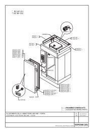
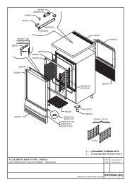
Spare parts4.11.2004 Rev. 1.1ID Code Model Type DescriptionModule:Refrigeration unit and EvaporatorRefrigeration unit60 141555100055 BT 70,72 Compressor SC 15 CL60 141555100065 BT 140,144 Compressor SC 21 CL60 141555100055 BTV 70 Compressor SC 15 CL60 141555100065 BTV 140 Compressor SC 21 CL70 Relay starter80 1665007 BT Clixon80 1665007 BTV Clixon90 Capacitor100 141622524139 BT 70,72 Condenser100 141622800020 BT 140,144 Condenser100 141622524139 BTV 70 Condenser100 141622800020 BTV 140 Condenser110 1648020182 BT 70,72 Motor, fan 23W110 1648001200 BT 140,144 Motor, fan 12W110 1648020182 BTV 70 Motor, fan 23W110 1648001200 BTV 140 Motor, fan 12WEvaporator120 14330570134 BT 70,72 Evaporator, complete120 14330540134 BT 140,144 Evaporator, complete120 14330570134 BTV 70 Evaporator, complete120 14330540134 BTV 140 Evaporator, complete130 1648001015 70,72 Motor, fan 10W130 1648001200 140,144 Motor, fan 12W150 1666353 BT 70,72 Heating element, evaporator defrost 350W150 1666700 BT 140,144 Heating element, evaporator defrost 700W150 1666353 BTV 70,72 Heating element, evaporator defrost 350WBT=BT, BTV=BTV70=70, 72=72, 140=140, 144=144H=HACCP thermostat, RC=Remote cooling, W=CastersP=1/N/PE~220-240V 50Hz29
Spare parts4.11.2004 Rev. 1.130
Spare parts4.11.2004 Rev. 1.1ID Code Model Type DescriptionModule:Refrigeration unit and Evaporator150 1666700 BTV 140,144 Heating element, evaporator defrost 700W20 1440290 Fan protection grillBT=BT, BTV=BTV70=70, 72=72, 140=140, 144=144H=HACCP thermostat, RC=Remote cooling, W=CastersP=1/N/PE~220-240V 50Hz31
Spare parts4.11.2004 Rev. 1.132
Spare parts4.11.2004 Rev. 1.1ID Code Model Type DescriptionModule:Electric components and ThermostatElectric components- 165820 BTV Lamp 36W160 1640403 BT Lamp 25W170 165705 BT Bulb socket- 165822 BTV Starter holder lamp- 1658011 BTV Starting switch for lamp- 1658224 BTV Lamp protection- 165821 BTV Lamp support220 1666031 70,140 Heating element, door frame 31W220 1666040 72,144 Heating element, door frame 41W230 164606 Micro-switchThermostat240 14261056 Polycarbonate250 161502 BT Black hole cover260 1635110 Green switch ON-OFF270 1635112 BTV White light switch ON-OFF280 167211 BT NTC sensor280 167211 BTV NTC sensor280 167212 BT NTC sensor280 167212 BTV NTC sensor290 16814012 BT Thermostat ID-974290 16814012 BTV Thermostat ID-974300 1681191 Thermostat seal340 1412062 HingeBT=BT, BTV=BTV70=70, 72=72, 140=140, 144=144H=HACCP thermostat, RC=Remote cooling, W=CastersP=1/N/PE~220-240V 50Hz33
Spare parts4.11.2004 Rev. 1.134
Spare parts4.11.2004 Rev. 1.1ID Code Model Type Accessory DescriptionModule:General parts and DoorGeneral parts- 164201 Glass for light30 1467515 Round foot40 147807 W Caster50 147808 W Caster with brakeDoor310 1412086 BT Cabinet hinges housing320 1468002 BT Lock housing330 1483009 Key- 1484003 72,144 Centre hinge360 1484001 BT Lower hinge360 1484002 BT Lower hinge370 14415991559 70,140 Door gasket 599x1559370 14415990738 72,144 Door gasket 599x738380 1412083 BT Right spring for door380 1412084 BT Left spring for door390 32630596 BT 70,140 Door390 32630597 BT 72,144 Door400 32250596 BT 70,140 Door with gasket400 32250597 BT 72,144 Door with gasket- 1470027 BTV Glass door, right- 1470028 BTV Glass door, left420 1483003 BT Cylinder lock430 1412082 Hinge holding bracket- 14120475 BTV Hinge holding bracket- 14120477 BTV Hinge holding bracket- 14120476 BTV Hinge holding bracketModule:General parts and Door- 14120478 BTV Hinge holding bracketBT=BT, BTV=BTV70=70, 72=72, 140=140, 144=144H=HACCP thermostat, RC=Remote cooling, W=CastersP=1/N/PE~220-240V 50Hz35
Spare parts4.11.2004 Rev. 1.136
Technical specifications4.11.2004 Rev. 1.19. Technical specificationsMotorised refrigeration circuit diagramRefrigeration circuit diagram of remote-refrigerated appliancesWiring diagram BT, BTVInstallation drawing BT, 70Installation drawing BT, 72Installation drawing BTV, 70Installation drawing BT, 140Installation drawing BT, 144Installation drawing BTV, 14037
Technical specifications4.11.2004 Rev. 1.1Motorised refrigeration circuit diagramDescription1 Compressor2 Condenser3 Filter drier dirty4 Capillary tube5 Evaporator38
Technical specifications4.11.2004 Rev. 1.1Refrigeration circuit diagram of remote-refrigerated appliancesDescription1 Compressor2 Condenser3 Filter drier dirty4 Valve5 Evaporator6 Will be borne by the installer39
Wiring diagram BT, BTV
Technical specifications4.11.2004 Rev. 1.1DescrizioneDescrizioneHL1 CABINET LIGHTING R3 DRAIN HEATERKA1 FAN AND LIGHTING RELAY SQ DOOR SWITCHKM POWER RELAY ST1 ELECTRONIC CABINET THERMOSTATM1 MOTOR COMPRESSOR YV2 BY-PASS SOLENOID VALVEM2 CONDENSER MOTOR FAN 1 FOR 120/140 VERSION ONLYM3 CABINET MOTOR FAN 11 ONLY ON REQUESTQM1 MAIN SWITCH 14AVAILABLE ON REMOTE-REFRIGERATEDUNITS ONLYR DEFROST HEATER 15NOT AVAILABLE ON REMOTEREFRIGER-ATED UNITSR1 CONDENSATE TRAY HEATER 16NOT AVAILABLE ON GLASS DOOR MOD-ELSR2 DOOR FRAME HEATER41
Technical specifications4.11.2004 Rev. 1.1Installation drawing BT, 7042
Technical specifications4.11.2004 Rev. 1.1Installation drawing BT, 7243
Technical specifications4.11.2004 Rev. 1.1Installation drawing BTV, 7044
Technical specifications4.11.2004 Rev. 1.1Installation drawing BT, 14045
Technical specifications4.11.2004 Rev. 1.1Installation drawing BT, 14446
Technical specifications4.11.2004 Rev. 1.1Installation drawing BTV, 14047
Technical specifications4.11.2004 Rev. 1.1ItemModel Type SpecificationNominal gross volume 70,7 600 l.Nominal gross volume 140 1300 l.Package dimensions WxDxH 70,7 760 x 880 x 2230Package dimensions WxDxH 140 1460 x 880 x 2230Volume with package 70,7 1,5 m3Volume with package 140 2,9 m3Total weight BT 70,7 145 KgTotal weight BT 140 235 KgTotal weight BTV 70 151 KgTotal weight BTV 140 247 KgVoltage 230/1/50Power of compressor BT 70,7 452 W (CECOMAF -30+45)Power of compressor BT 140 617 W (CECOMAF -30+45)Power of compressor BTV 70 542 W (CECOMAF -30+45)Power of compressor BTV 140 617 W (CECOMAF -30+45)Working temperature BT -21 / -18 °CWorking temperature BTV -20 / -15 °CRefrigerant feedCapillaryRefrigeration systemVentilatedType of defrostElectricalDefrosts per day / Defrost duration time (min)4 / 30 minutesCurrent absorbed during operation BT 70,7 3,0 ACurrent absorbed during operation BT 140 4,3 ACurrent absorbed during operation BTV 70 3,5 ACurrent absorbed during operation BTV 140 4,3 AMax current absorbed BT 70,7 3,3 AMax current absorbed BT 140 4,3 AMax current absorbed BTV 70 3,5 AMax current absorbed BTV 140 4,3 APower absorbed during operation BT 70,7 443 WPower absorbed during operation BT 140 830 WPower absorbed during operation BTV 70 700 WPower absorbed during operation BTV 140 830 WMax power absorbed BT 70,7 760 WMax power absorbed BT 140 830 WMax power absorbed BTV 70 700 WMax power absorbed BTV 140 830 WFuse16ARefrigerant type BT R404ARefrigerant type BTV R404AQuantity of refrigerant BT 70,7 360 grQuantity of refrigerant BT 140 400 grQuantity of refrigerant BTV 70 355 grQuantity of refrigerant BTV 140 400 grHeat emitted BT 70,7 685 W48
Technical specifications4.11.2004 Rev. 1.1ItemHeat emitted BT 140 720 WHeat emitted BTV 70 1000 WHeat emitted BTV 140 720 WAir capacity BT 70,7 390 m3/hAir capacity BT 140 450 m3/hAir capacity with filter BTV 70 390 m3/hAir capacity BTV 140 450 m3/hBT=BT, BTV=BTV70=70, 72=72, 140=140, 144=144H=HACCP thermostat, RC=Remote cooling, W=CastersP=1/N/PE~220-240V 50HzModel Type Specification49
DICHIARAZIONE DI CONFORMITA’DECLARATION OF CONFORMITYKONFORMITÄTSERKLÄRUNGDECLARACIÓN DE CONFORMIDADDECLARATION CE DE CONFORMITECostruttore / Manufacturer / Hersteller / Producteur /FabricanteMacchinario / Machine / Bezeichnung der Machine / Machine /MáquinaTipo, Modello / Type, Model / Maschinentyp / Type, Modèle /Tipo, Modeloinizio produzione / production start / debut production /producto a partir de / Produktions-Beginn<strong>Polaris</strong> SpAVia Cavalieri di Vittorio Veneto 2532030 Bribano di Sedico (BL)Frigorifero-ConservatoreSPA BT 70/P; SPA BT 72/PSPA TNN 70/P; SPA TNN 72/PSPA BT 140/P; SPA BT 144/PSPA TNN 140/P; SPA TNN 144/PSPA B 120/P; SPA B 240/P04Si dichiara che l’apparecchiatura di nostra produzione, specificata sopra, è progettata e costruita in conformità ai requisiti essenziali di sicurezzadettati dalla Direttiva Europea sulla Sicurezza. Vi rammentiamo che la presente dichiarazione perde validità in caso di modifichedell’apparecchiatura eseguite senza il nostro consenso.It is hereby declared that the mentioned machine manufactured by us is designed and manufactured in compliance with the essential safetyrequirements as provided under the European Directive on Safety. May we remind you that the present declaration shall be null and void shouldany modifications be carried out on the machine without our approval.Hiermit erklären wir, daß die bezeichnete Maschine bei uns hergestellt aufgrund ihren Konzipierung und Bauart sowie in der von uns in VerkehrAusfuhrung den einschlagigen grundlegenden Sicherheitsanforderungen der EG-Maschinenrichtline entspricht. Bei einer mit uns nichtabgestimmten Änderung der Maschine verliert diese Erklärung ihre Gültigkeit.Nous déclarons que la machine de notre production spécifiée a été conçue et construite de façon à répondre aux conditions essentiellesrequises en matière de sécurité dictées par la Directive Européenne sur la Sécurité. Nous vous rappelons que la présente déclaration perdra savalidité en cas de modifications apportées à la machine sans notre autorisation.El fabricante declara que la máquina de su producción especificada fue proyectada y fabricada de conformidad con los requisitos esenciales deseguridad prescritos en la Directiva europea sobre las seguridad. Se deja constancia de que la presente declaración perderá su validez en casode que se realicen modificaciones en los productos sin previa autorización del fabricante.Direttive di riferimento:Direttiva Bassa Tensione 73/23/EECDirettiva Compatibilità Elettromagnetica 89/336/EECDirettiva 93/68/EECNorme applicate in particolare: EN 60335-1:94 A16:01 EN 55014-2: 97 A1:01EN 60335-2-24: 00 EN 61000-3-2: 00 A1:01EN 55014-1: 00 A2:02 EN 61000-3-3: 95 A1:00Relevant Directives:Low Voltage Directive 73/23/EECElectromagnetic Compatibility Directive 89/336/EECDirettiva 93/68/EECSpecifically applied standards: EN 60335-1:94 A16:01 EN 55014-2: 97 A1:01EN 60335-2-24: 00 EN 61000-3-2: 00 A1:01EN 55014-1: 00 A2:02 EN 61000-3-3: 95 A1:00Einschlägige EG-Richtlinien:EG-Niederspannungsrichtline 73/23/EWGEG -Richtline Elektromagnetische Verträglickeit 89/336/EECEG Richtlinie 93/68 CEEAngewandte Normen, insbesondere: EN 60335-1:94 A16:01 EN 55014-2: 97 A1:01EN 60335-2-24: 00 EN 61000-3-2: 00 A1:01EN 55014-1: 00 A2:02 EN 61000-3-3: 95 A1:00Directives de référence:Directive Basse Tension 73/23/CEEDirective Compatibilité Èlectromagnétique 89/336/EECDirective 93/68 CEENormes appliquées en particulier: EN 60335-1:94 A16:01 EN 55014-2: 97 A1:01EN 60335-2-24: 00 EN 61000-3-2: 00 A1:01EN 55014-1: 00 A2:02 EN 61000-3-3: 95 A1:00Identificazione del firmatario / Identification of signer / Angaben zum Unterzeichner / Identification dusignataire / Identificación del firmanteL’Amministratore DelegatoPaolo Candiago
DICHIARAZIONE DI CONFORMITA’DECLARATION OF CONFORMITYKONFORMITÄTSERKLÄRUNGDECLARACIÓN DE CONFORMIDADDECLARATION CE DE CONFORMITECostruttore / Manufacturer / Hersteller / Producteur /FabricanteMacchinario / Machine / Bezeichnung der Machine / Machine /MáquinaTipo, Modello / Type, Model / Maschinentyp / Type, Modèle /Tipo, Modeloinizio produzione / production start / debut production /producto a partir de / Produktions-Beginn<strong>Polaris</strong> SpAVia Cavalieri di Vittorio Veneto 2532030 Bribano di Sedico (BL)Frigorifero-ConservatoreSPA BTV 70/P; SPA TNV 70/PSPA BTV 140/P; SPA TNV 140/P04Si dichiara che l’apparecchiatura di nostra produzione, specificata sopra, è progettata e costruita in conformità ai requisiti essenziali di sicurezzadettati dalla Direttiva Europea sulla Sicurezza. Vi rammentiamo che la presente dichiarazione perde validità in caso di modifichedell’apparecchiatura eseguite senza il nostro consenso.It is hereby declared that the mentioned machine manufactured by us is designed and manufactured in compliance with the essential safetyrequirements as provided under the European Directive on Safety. May we remind you that the present declaration shall be null and void shouldany modifications be carried out on the machine without our approval.Hiermit erklären wir, daß die bezeichnete Maschine bei uns hergestellt aufgrund ihren Konzipierung und Bauart sowie in der von uns in VerkehrAusfuhrung den einschlagigen grundlegenden Sicherheitsanforderungen der EG-Maschinenrichtline entspricht. Bei einer mit uns nichtabgestimmten Änderung der Maschine verliert diese Erklärung ihre Gültigkeit.Nous déclarons que la machine de notre production spécifiée a été conçue et construite de façon à répondre aux conditions essentiellesrequises en matière de sécurité dictées par la Directive Européenne sur la Sécurité. Nous vous rappelons que la présente déclaration perdra savalidité en cas de modifications apportées à la machine sans notre autorisation.El fabricante declara que la máquina de su producción especificada fue proyectada y fabricada de conformidad con los requisitos esenciales deseguridad prescritos en la Directiva europea sobre las seguridad. Se deja constancia de que la presente declaración perderá su validez en casode que se realicen modificaciones en los productos sin previa autorización del fabricante.Direttive di riferimento:Direttiva Bassa Tensione 73/23/EECDirettiva Compatibilità Elettromagnetica 89/336/EECDirettiva 93/68/EECNorme applicate in particolare: EN 60335-1:94 A16:01 EN 55014-2: 97 A1:01EN 60335-2-24: 00 EN 61000-3-2: 00 A1:01EN 55014-1: 00 A2:02 EN 61000-3-3: 95 A1:00Relevant Directives:Low Voltage Directive 73/23/EECElectromagnetic Compatibility Directive 89/336/EECDirettiva 93/68/EECSpecifically applied standards: EN 60335-1:94 A16:01 EN 55014-2: 97 A1:01EN 60335-2-24: 00 EN 61000-3-2: 00 A1:01EN 55014-1: 00 A2:02 EN 61000-3-3: 95 A1:00Einschlägige EG-Richtlinien:EG-Niederspannungsrichtline 73/23/EWGEG -Richtline Elektromagnetische Verträglickeit 89/336/EECEG Richtlinie 93/68 CEEAngewandte Normen, insbesondere: EN 60335-1:94 A16:01 EN 55014-2: 97 A1:01EN 60335-2-24: 00 EN 61000-3-2: 00 A1:01EN 55014-1: 00 A2:02 EN 61000-3-3: 95 A1:00Directives de référence:Directive Basse Tension 73/23/CEEDirective Compatibilité Èlectromagnétique 89/336/EECDirective 93/68 CEENormes appliquées en particulier: EN 60335-1:94 A16:01 EN 55014-2: 97 A1:01EN 60335-2-24: 00 EN 61000-3-2: 00 A1:01EN 55014-1: 00 A2:02 EN 61000-3-3: 95 A1:00Identificazione del firmatario / Identification of signer / Angaben zum Unterzeichner / Identification dusignataire / Identificación del firmanteL’Amministratore DelegatoPaolo Candiago
M_SPABT_uen11.pdf