Bruksanvisning för bord till handöverfräs Bruksanvisning for ... - Jula
Bruksanvisning för bord till handöverfräs Bruksanvisning for ... - Jula
Bruksanvisning för bord till handöverfräs Bruksanvisning for ... - Jula

Create successful ePaper yourself
Turn your PDF publications into a flip-book with our unique Google optimized e-Paper software.
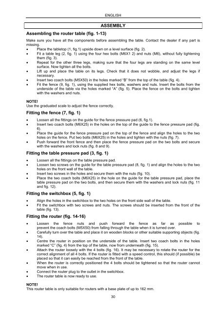
Assembling the router table (fig. 1-13)<br />
ENGLISH<br />
ASSEMBLY<br />
Make sure you have all the components be<strong>for</strong>e assembling the table. Contact the dealer if any part is<br />
missing.<br />
• Place the tabletop (1, fig.1) upside down on a level surface (fig. 2).<br />
• Fit a table leg (2, fig. 1) using the four hex bolts (M6X1 2) and nuts (M6), without fully tightening<br />
them (fig. 3).<br />
• Repeat <strong>for</strong> the other three legs, making sure that the four legs are standing on the same level<br />
surface. Now tighten all the bolts.<br />
• Lift up and place the table on its legs. Check that it does not wobble, and adjust the legs if<br />
necessary.<br />
• Insert two coach bolts (M5X50) in the holes marked “B” from the top of the table (fig. 4).<br />
• Fit the fence (9, fig. 1), using the supplied hex bolts, washers and nuts. Insert the bolts from the<br />
underside of the table via the holes marked “A” (fig. 5). Place the fence on the bolts and tighten<br />
with the washers and nuts.<br />
NOTE!<br />
Use the graduated scale to adjust the fence correctly.<br />
Fitting the fence (7, fig. 1)<br />
• Loosen all the fittings on the guide <strong>for</strong> the fence pressure pad (6, fig.1).<br />
• Insert two coach bolts (M6X25) in the holes on the top of the guide to the fence pressure pad (fig.<br />
6).<br />
• Place the guide <strong>for</strong> the fence pressure pad on the top of the fence and align the holes to the two<br />
holes on the fence. Put two bolts (M6X25) in the holes and tighten with the nuts (fig. 7).<br />
• Push <strong>for</strong>ward the front fence and then place the fence pressure pad on the two bolts and secure<br />
with the washers and lock nuts (fig. 8 and 9).<br />
Fitting the table pressure pad (3, fig. 1)<br />
• Loosen all the fittings on the table pressure pad.<br />
• Loosen two screws on the guide <strong>for</strong> the table pressure pad (8, fig. 1) and align the holes to the two<br />
holes on the front wall of the table.<br />
• Insert two screws in the holes and secure them with the nuts (fig. 10).<br />
• Place the two coach bolts (M6X25) in the hole on the guide <strong>for</strong> the table pressure pad, place the<br />
table pressure pad on the two bolts, and then secure them with the washers and lock nuts (fig. 11<br />
and fig. 12).<br />
Fitting the switchbox (5, fig. 1)<br />
• Align the holes in the switchbox to the two holes on the front side wall of the table.<br />
• Fit the switchbox with two screws and nuts. The screws should be inserted from the front of the<br />
table (fig. 13).<br />
Fitting the router (fig. 14-16)<br />
• Loosen the fence nuts and push <strong>for</strong>ward the fence as far as possible to<br />
prevent the coach bolts (M5X50) from falling through the table when it is turned over.<br />
• Carefully turn over the table and place it on wooden blocks or other suitable supporting objects (fig.<br />
14).<br />
• Centre the router in position on the underside of the table. Insert two coach bolts in the holes<br />
marked “C” (fig. 4) from the top of the table, now from underneath (fig. 15).<br />
• Attach the router loosely with the 4 bolts (fig. 16). It may be necessary to rotate the router <strong>for</strong> the<br />
correct alignment of all 4 bolts. If the router is fitted with a speed control, this should (if possible) be<br />
placed so that it can easily be reached from the front of the table.<br />
• When the router is correctly positioned the 4 bolts should be tightened so that the router cannot<br />
move when in use.<br />
• Connect the router plug to the outlet in the switchbox.<br />
• The router table is now ready to use.<br />
NOTE!<br />
This router table is only suitable <strong>for</strong> routers with a base plate of up to 162 mm.<br />
30