CR-101 OBDII felkODsläsaRe feIlkODeleseR ... - Biltema
CR-101 OBDII felkODsläsaRe feIlkODeleseR ... - Biltema
CR-101 OBDII felkODsläsaRe feIlkODeleseR ... - Biltema

You also want an ePaper? Increase the reach of your titles
YUMPU automatically turns print PDFs into web optimized ePapers that Google loves.
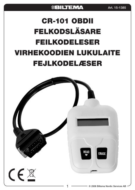
<strong>CR</strong>-<strong>101</strong> <strong>OBDII</strong><br />
<strong>felkODsläsaRe</strong><br />
<strong>feIlkODeleseR</strong><br />
1<br />
Art. 15-1385<br />
vIRhekOODIen lukulaIte<br />
fejlkODelæseR<br />
© 2008 <strong>Biltema</strong> Nordic Services AB
InnehållsföRteCknIng<br />
Introduktion<br />
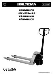
Vad gör <strong>CR</strong>-<strong>101</strong> kodläsare?<br />
Kodläsarens delar<br />
säkerhetsinstruktioner<br />
föreberedelser före test<br />
Placering av datalänk-kontakten<br />
Läsa diagnostiska felkoder<br />
använda kodläsaren<br />
Hämta felkoder<br />
Radera felkoder<br />
Ingen kommunikation<br />
Installera programvara<br />
Läsa diagnostiska felkodsdefinitioner<br />
usB anslutning<br />
generiska felkodsdefinitioner<br />
© 2008 <strong>Biltema</strong> Nordic Services AB<br />
<strong>CR</strong>-<strong>101</strong> <strong>OBDII</strong> <strong>felkODsläsaRe</strong><br />
IntRODuktIOn<br />
Alla nyare fordon har OBD (on-board diagnosis).<br />
Årsmodeller från 1996 till 2002 har <strong>OBDII</strong><br />
och från årsmodell 2002 och framåt har EOBD.<br />
<strong>CR</strong>-<strong>101</strong> kodläsare fungerar på alla <strong>OBDII</strong> eller<br />
EOBD kompatibla fordon.<br />
Om fordonets ECU upptäcker ett kommunikationsproblem<br />
med någon eller några av bilens<br />
olika sensorer lagras en felkod i ECUn. Dessutom<br />
tänds kontrollampan för motorelektronik<br />
för att informera föraren.<br />
<strong>CR</strong><strong>101</strong> kodläsare hämtar alla diagnostiska<br />
felkoder via en 16-polig universell Datalänkkontakt<br />
som normalt sitter under instrumentpanelen.<br />
Felkoderna underlättar felsökning<br />
och reparation.<br />
Observera följande<br />
• Varje diagnostisk felkod varnar för ett<br />
problem eller symptom som uppstått i ett<br />
system, inte i en specifik del.<br />
• Fordonets ECU kan bara rapportera fel<br />
som indikerats av systemet olika sensorer.<br />
2<br />
1<br />
2<br />
3<br />
Art. 15-1385<br />
• Det finns exempel på att sensorer kan<br />
verka trasiga även om de inte är det.<br />
Orsaken kan vara:<br />
Dåliga anslutningar, trasiga kablar eller<br />
kortslutningar kan orsaka felaktiga<br />
sensorsignaler till databoxen.<br />
Fel i ett system kan påverka sensorerna<br />
i ett annat system som då resulterar<br />
i en felaktig signal till databoxen.<br />
• Vi rekommenderar att man har tillgång till<br />
bilens servicemanual vid felsökningsprocessen.<br />
Nästa steg i diagnostiseringsprocessen är att<br />
testa de system som misstänks vara felaktiga.<br />
När felet är identifierat och reparerat kan<br />
kodläsaren användas för att radera koderna<br />
från fordonets databox. Felindikeringslampan<br />
släcks när felkoderna är raderade.<br />
kODläsaRens DelaR<br />
5<br />
1. Display<br />
Visar instruktioner och diagnostiska felkoder.<br />
2. Knappen READ<br />
Tryck på knappen för att läsa in felkoderna och<br />
för att visa nästa felkod.<br />
3. Knappen ERASE<br />
Tryck på knappen för att radera felkoderna<br />
från fordonets databox.<br />
4. <strong>OBDII</strong> hankontakt<br />
Ansluts till datalänk-kontakten i fordonet.<br />
5. USB-port<br />
<strong>CR</strong><strong>101</strong> ansluts till en persondator via en<br />
USB-kabel för att visa lagrade felkoder och<br />
definitioner.<br />
4
säkeRhetsInstRuktIOneR<br />
För att förhindra olyckor med allvarliga personskador,<br />
skador på fordonet eller testutrustningen<br />
ska säkerhetsinstruktionerna följas.<br />
När motorn är igång bildas avgaser<br />
som innehåller kolmonoxid. Se till<br />
att ventilationen är tillfredställande.<br />
Andas aldrig in avgaser.<br />
Bränsleånger är mycket brandfarliga.<br />
Förhindra gnistbildning,<br />
öppen eld och rökning i närheten av<br />
fordonet.<br />
När motorn är igång är det många<br />
delar som snurrar med hög hastighet<br />
t ex fläktrem. Håll alltid ett<br />
säkerhetsavstånd till dessa delar.<br />
Bär inte löst sittande kläder eller<br />
smycken vid arbete med motorn.<br />
Löst sittande kläder kan fastna i<br />
rörliga delar. Smycken kan bli strömförande<br />
och ge brännskador.<br />
Se till att handbromsen är åtdragen<br />
innan motorn startas för test och<br />
felsökning. Har bilen automatisk<br />
växellåda, lägg den i läge P. Bil med<br />
manuell växellåda läggs i friläge.<br />
Blockera alltid de drivande hjulen så<br />
att bilen inte kan börja rulla. Lämna<br />
aldrig bilen utan uppsikt.<br />
Delar av motorn blir mycket heta<br />
när motorn är igång. Rör aldrig heta<br />
motordelar.<br />
Lägg aldrig verktyg på bilbatteriet.<br />
Det kan orsaka kortslutning vilket<br />
kan skada dig, verktyget eller batteriet.<br />
3<br />
Art. 15-1385<br />
Undvik kontakt med högspänningskomponenterna<br />
(tändpolar,<br />
strömfördelarlock, tändkablar och<br />
tändstift) när motorn är igång.<br />
Slå alltid ifrån tändningen innan<br />
<strong>CR</strong>-<strong>101</strong> kodläsaren ansluts.<br />
Se till att en brandsläckare finns<br />
tillgånglig under arbetet.<br />
försiktighet:<br />
En del fordon är utrustade med krockkudde.<br />
Följ försiktighetsåtgärderna enligt fordonets<br />
servicemanual vid arbete i närheten av komponenter<br />
och kablar till krockkudden. Följs inte<br />
instruktionerna kan krockkudden lösa ut och<br />
orsaka personskador.<br />
Krockkudden kan lösa ut flera minuter efter<br />
att tändningen slagits ifrån eller bilbatteriet<br />
kopplats bort eftersom krockkudden har en<br />
speciell modul för reservspänning.<br />
Följ alltid tillverkarens försiktighetsåtgärder<br />
och serviceprocedurer.<br />
föreberedelser före test<br />
Placering av datalänk-kontakten<br />
Datalänk-kontakten är en standardiserad<br />
J1962-kontakt som används i alla fordon med<br />
<strong>OBDII</strong>-system.<br />
Specifikationen för J1962-kontakten definierar<br />
även placeringen av Datalänk-kontakten i<br />
fordonet. Se nedanstående figur.<br />
Områden för placering av<br />
Datalänk-kontakten.<br />
<strong>OBDII</strong>-kontakt<br />
Förarsidan Passagerarsidan<br />
Rekommenderad placering av kontakten<br />
© 2008 <strong>Biltema</strong> Nordic Services AB
POsItIOn BeskRIvnIng<br />
1 Förarsidan, under instrumentpanelen i området under styrkolonnen,<br />
+/-150 mm på varje sida om styrkolonnen.<br />
2 Förarsidan, under instrumentpanelen mellan förarsidans dörr och<br />
styrkolonnen.<br />
© 2008 <strong>Biltema</strong> Nordic Services AB<br />
4<br />
Art. 15-1385<br />
3 Förarsidan, under instrumentpanelen, mellan styrkolonnen och mittkonsolen<br />
(inkluderar även kontakter på förarsidan som är anslutna till mittkonsolen).<br />
4 Förarsidan, instrumentpanelen/området där mätinstrumenten sitter, mellan<br />
styrkolonnen och mittkonsolen.<br />
5 Förarsidan, instrumentpanelen/området där mätinstrumenten sitter, mellan<br />
förarsidans dörr och styrkolonnen.<br />
6 Mittkonsolen, vertikal placering i närheten av radio och klimatanläggning.<br />
6/7 Mittkonsolen, vertikal placering i närheten ar radio och klimatanläggning.<br />
7 Mittkonsolen, vertikal placering till höger om bilens centrumlinje eller på<br />
passagerarsidan av mittkonsolen.<br />
8 Mittkonsolen, horisontell placering t ex i området där armstöd och<br />
handbroms sitter, framför passagerarplatsen.<br />
9 Annan placering än position 1–8 t ex passagerarutrymmet, handskfacket,<br />
ovanför instrumentpanelen nära vindrutan.<br />
OBseRveRa<br />
• Position 1–3 är rekommenderad placering, position 4–8 är tillåten placering<br />
• Anslutningar i position 6/7 och 7 kan vara täckta av askkopp, täckplattor, mugghållare,<br />
mynthållare etc.<br />
läsa DIagnOstIska felkODeR<br />
När en kontrollenhet känner igen och identifierar<br />
ett problem lagras en diagnostisk felkod i<br />
databoxen. Dessa felkoder hjälper användaren<br />
att hitta orsaken till problemet.<br />
tolka diagnostiska felkoder<br />
• Det första tecknet i felkoden identifierar<br />
i vilket huvudsystem felet uppstått (drivkedja,<br />
kaross, chassi eller nätverk).<br />
• Det andra tecknet identifierar typ av kod,<br />
generisk eller tillverkarspecifik.<br />
• Det tredje tecknet identifierar det system<br />
där problemet uppstått.<br />
• Det fjärde och femte tecknet identifierar<br />
vilken del av systemet som inte fungerar.<br />
Exempel på tolkning av felkoder<br />
Bx=Kaross<br />
Cx=Chassi<br />
Px=Drivlina<br />
Ux=Fordonets Nätverk<br />
X=1, 2 eller 3<br />
P 0 1 0 1<br />
Identifierar det system<br />
där problemet uppstått.<br />
Identifierar vilken del<br />
av systemet som inte<br />
fungerar
Exempel<br />
P0<strong>101</strong> – Problem med luftkylningen<br />
Koder för drivlina<br />
P0xxx – Generisk (SAE)<br />
P1xxx – Tillverkarspecifik<br />
P2xxx – Generisk (SAE)<br />
P30xx – P33xx Tillverkarspecifik<br />
P34xx – P39xx – Generisk (SAE)<br />
Koder för Chassi<br />
C0xxx – Generisk (SAE)<br />
C1xxx – Tillverkarspecifik<br />
C2xxx – Tillverkarspecifik<br />
C3xxx – Generisk (SAE)<br />
Koder för Kaross<br />
B0xxx – Generisk (SAE)<br />
B1xxx – Tillverkarspecifik<br />
B2xxx – Tillverkarspecifik<br />
B3xxx – Generisk (SAE)<br />
Koder för nätverkskommunikation<br />
U0xxx – Generisk (SAE)<br />
U1xxx – Tillverkarspecifik<br />
U2xxx – Tillverkarspecifik<br />
U3xxx – Generisk (SAE)<br />
Fordonsspecifika system<br />
1. Bränsle- och luftmätning<br />
2. Bränsle- och luftmätning (endast fel i bränsleinsprutning)<br />
3. Tändningssystem eller misständning<br />
4. Extra avgaskontrollsystem<br />
5. Fordonets hastighetskontroll och tomgångskörning<br />
6. Databoxens utgångskretsar<br />
7. Transmission<br />
8. Transmission<br />
använDa kODläsaRen<br />
Se till att alla mekaniska problem som låg oljenivå,<br />
skadade slangar, kablar och elektriska<br />
anslutningar är åtgärdade innan <strong>CR</strong><strong>101</strong> ansluts<br />
och används på fordonet. Den här typen av fel<br />
kan generera felaktiga diagnostiska felkoder.<br />
Kontrollera följande innan testen startas:<br />
• Kontrollera nivån på motorolja, olja till servostyrning,<br />
transmissionsolja, kylarvätska<br />
och andra vätskor.<br />
5<br />
Art. 15-1385<br />
• Kontrollera att luftslangarna är hela och att<br />
luftfiltret är rent.<br />
• Se till att kuggremmen är hel och korrekt<br />
spänd.<br />
• Se till att tändstiften är rengjorda och i gott<br />
skick. Kontrollera även att tändkablarna är<br />
hela och korrekt anslutna.<br />
• Se till att alla mekaniska länkar till motorsensorerna<br />
(gasreglage, växelposition)<br />
är väl anslutna. Se service manualen för<br />
placering.<br />
• Kontrollera alla elektriska kablar så att de<br />
är korrekt anslutna och väl isolerade.<br />
• Kontrollera alla gummislangar och stålrör<br />
(vakuum och bränsle) så att de inte läcker,<br />
är igensatta eller skadade.<br />
• Kontrollera motorkompression och tändning.<br />
• För information om service- och reparationsprocedurer<br />
hänvisas till fordonets<br />
servicemanual.<br />
hämta in felkoder<br />
När alla förberedelser är gjorda kan testningen<br />
påbörjas.<br />
1. Slå ifrån tändningen.<br />
2. Leta upp Datalänk-kontakten<br />
(vanligtvis under<br />
instrumentpanelen)<br />
och anslut<br />
kodläsaren. Nu<br />
visas PRESS<br />
READ i displayen.<br />
3. Slå på tändningen<br />
utan att<br />
starta motorn.<br />
© 2008 <strong>Biltema</strong> Nordic Services AB
4. Tryck på knappen READ. Nu kommunicerar<br />
kodläsaren med fordonets databox.<br />
WAIT<br />
----------<br />
NO CODE<br />
P0305<br />
P0305 1<br />
P1233(5<br />
WAIT<br />
© 2008 <strong>Biltema</strong> Nordic Services AB<br />
5. Under tiden<br />
kommunikation<br />
sker visas WAIT i<br />
displayen.<br />
6. Efter ca 1 sekund<br />
börjar kodläsaren<br />
att hämta<br />
felkoderna från<br />
minnet och visa<br />
dem i displayen.<br />
7. Finns inga<br />
felkoder i minnet<br />
visas NO CODE i<br />
displayen.<br />
Finns endast en<br />
felkod visas den i<br />
displayen.<br />
Har kodläsaren<br />
hämtat fler diagnostiska<br />
felkoder stegar<br />
du genom listan av<br />
koder med knappen<br />
READ.<br />
Tryck och håll ner<br />
knappen READ i<br />
5 sekunder för att<br />
hämta felkoder<br />
igen.<br />
6<br />
CLEAR?<br />
----------<br />
CLR OK<br />
NO LINK<br />
Art. 15-1385<br />
Radera felkoder<br />
De diagnostiska felkoderna kan raderas från<br />
fordonets databox med kodläsaren. Använd<br />
funktionen endast då fordonet har testats och<br />
reparerats.<br />
Visas samma felkod igen har inte problemet<br />
åtgärdats eller så finns det ytterligare fel som<br />
påverkar samma sensor.<br />
1. Tryck på ERASE. Kodläsaren börjar kommunicera<br />
med databoxen i fordonet.<br />
2. Efter en stund<br />
visas CLEAR? i<br />
displayen.<br />
3. Tryck på knappen ERASE för att radera<br />
felkoderna från styrenheten i bilen.<br />
4. Under raderingsprocessen<br />
visas följande på<br />
displayen.<br />
5. När felkoderna<br />
är raderade<br />
från databoxen<br />
visas CLR OK i<br />
displayen.<br />
Ingen kommunikation<br />
Om kodläsaren inte kan kommunicera med<br />
fordonets databox visas NO LINK i displayen.<br />
Kodläsaren gör 5 försök med 5 olika protokoll.<br />
Kommunikationsproblem kan orsakas av:<br />
• Bilen är inte EOBD/<strong>OBDII</strong> kompatibel. Leta<br />
upp VECI dekalen, placerad någonstans i<br />
motorrummet.<br />
• Dålig kontakt i datalänk-kontakten, dra ur<br />
kontakten och sätt i den igen.
InstalleRa PROgRamvaRa<br />
applikationsprogrammet<br />
Applikationsprogrammet ska installeras på<br />
persondatorn innan kodläsaren ansluts till<br />
persondatorn. Installationen av applikationsprogrammet<br />
startas automatiskt när cd sätts i<br />
persondatorns cd-rom läsare. Följ proceduren<br />
enligt nedanstående bilder.<br />
7<br />
Art. 15-1385<br />
© 2008 <strong>Biltema</strong> Nordic Services AB
DRIvRutIneR föR usB-anslutnIng<br />
1. Anslut USB-kabeln mellan persondatorn<br />
och den 5-poliga mini-USB kontakten på<br />
kodläsaren. Windows letar efter anslutna<br />
enheter. Installationsprocessen startar<br />
automatiskt.<br />
2. Nu visas ”Ny maskinvara har hittats” på<br />
skärmen<br />
3. Se till att endast ”Install from a list or specified<br />
location ” (Advanced) är markerad.<br />
4. Klicka på ”Next”.<br />
© 2008 <strong>Biltema</strong> Nordic Services AB<br />
8<br />
Art. 15-1385<br />
5. Markera ”Search for the best driver in these<br />
locations” och ”Include this location in the<br />
search”.<br />
6. Klicka på “Browse”<br />
7. Leta upp E:\<strong>CR</strong><strong>101</strong>_DRIVER<br />
8. Kontrollera sökvägen till E:\<strong>CR</strong><strong>101</strong>_DRIVER<br />
9. Klicka på ”NEXT”<br />
10. Klicka på ”Continue anyway”
11. Klicka på ”Browse” och ange sökvägen<br />
E:\<strong>CR</strong><strong>101</strong>_DRIVER.<br />
12. Markera filen D12.sys och klicka på<br />
”Open”.<br />
9<br />
13. Klicka på ”OK”.<br />
14 . Klicka på ”Finish”<br />
Art. 15-1385<br />
© 2008 <strong>Biltema</strong> Nordic Services AB
läsa DIagnOstIska felkODsDefInItIOneR<br />
1. Installera programvaran till EOBD på persondatorn.<br />
2. Anslut medföljande USB-kabel mellan kodläsaren och persondatorn.<br />
3. Det som finns lagrat i kodläsaren visas automatiskt på datorskärmen.<br />
tyP fORDOn kOD DefInItIOn<br />
anslutnIng vIa usB<br />
1. Anslut kodläsaren till USB-uttaget på persondatorn<br />
via USB-kabeln. Kontrollera att<br />
kommunikationen fungerar genom att följa<br />
följande instruktioner:<br />
• Öppna Kontroll panelen (start\inställningar\kontrollpanelen)<br />
• Dubbelklicka på System.<br />
• Klicka på fliken Maskinvara.<br />
• Klicka på Enhetshanteraren.<br />
Om kommunikationen fungerar visas ”<strong>CR</strong>-<strong>101</strong><br />
USB link” på datorskärmen och ”PC MODE”<br />
på kodläsarens display.<br />
© 2008 <strong>Biltema</strong> Nordic Services AB<br />
10<br />
Art. 15-1385<br />
Pågående Generisk P0193 Fuel Rail Pressure Sensor High<br />
Input<br />
Pågående Chevrolet P1233 Fuel Pump Driver Module<br />
Disabled or Off Line (Fuel Pump<br />
Driver Module)<br />
Pågående Generisk P0xxx xxxx……..<br />
Lagrad Generisk …. …..<br />
2. Öppna programmet Code Definition. Nu<br />
visas följande på skärmen.<br />
• Klicka på LINK USB för att etablera<br />
kommunikation mellan persondator och<br />
kodläsare.<br />
• Klicka på GLOSSARY för att få förklaringar<br />
till förkortningar som används i definitionerna.<br />
• Klicka på HELP för att få information om<br />
programfunktionerna.<br />
• Klicka på About för information om programversionen.<br />
• Klicka på EXIT för att avsluta programmet.<br />
3. Se till att USB-kabeln mellan persondator<br />
och kodläsare är ordentligt ansluten. Välj<br />
Generic under Vehicle Search. Klicka på<br />
LINK USB. Nu visas definitionerna för de<br />
generiska felkoderna på skärmen.
4. Välj aktuell bilmodell, t ex Acura, under<br />
Vehicle Search för att visa definitionerna för<br />
de tillverkarspecifika felkoderna.<br />
5. Klicka på GLOSSARY för förklaring till<br />
förkortningar som används i definitionerna.<br />
Förkortningarna presenteras i bokstavsordning.<br />
6. Med funktionen CODE Search kan du söka<br />
efter en definition för specifik felkod genom<br />
att välja bilmodell och skriva in önskad<br />
felkod. Nu visas definitionen för angiven<br />
felkod.<br />
11<br />
Art. 15-1385<br />
7. Anges en felaktig felkod visas följande på<br />
skärmen.<br />
Observera<br />
Antalet felkoder och definitioner för en<br />
bilmodell förändras kontinuerligt. Fråga efter<br />
programvaruuppdateringar hos återförsäljaren<br />
för bilmodellen.<br />
avInstalleRa PROgRammen fRån<br />
WInDOWs XP<br />
Följ följande instruktioner för att avinstallera<br />
programvaran för <strong>CR</strong>-<strong>101</strong>.<br />
1. Klicka på Start<br />
2. Välj Inställningar/Kontollpanelen<br />
3. Välj Administrationsverktyg/Datorhantering/<br />
Enhetshantering<br />
4. Klicka på plustecknet (+) vid USB-styrenheter.<br />
5. Högerklicka på ”<strong>CR</strong>-<strong>101</strong> USB link”<br />
6. Välj avinstallera<br />
7. Starta om datorn<br />
DIagnOstIska<br />
felkODsDefInItIOneR<br />
Se s. 42.<br />
© 2008 <strong>Biltema</strong> Nordic Services AB
InnhOlDsfORtegnelse<br />
Innledning<br />
Hva gjør <strong>CR</strong>-<strong>101</strong> kodeleseren?<br />
Kodeleserens deler<br />
sikkerhetsinstruksjoner<br />
forberedelser før test<br />
Plassering av diagnosekontakt<br />
Lese diagnostiske feilkoder<br />
Bruke kodeleseren<br />
Hente feilkoder<br />
Slette feilkoder<br />
Ingen kommunikasjon<br />
Installere programvare<br />
Lese diagnostiske feilkodedefinisjoner<br />
usB-tilkobling<br />
generiske feilkodedefinisjoner<br />
InnleDnIng<br />
Alle nyere biler har OBD (on-board diagnosis).<br />
Årsmodeller fra 1996 til 2002 har <strong>OBDII</strong>, og<br />
årsmodell 2002 og nyere har EOBD. <strong>CR</strong>-<strong>101</strong><br />
kodeleseren fungerer på alle <strong>OBDII</strong>- eller<br />
EOBD-kompatible biler.<br />
Dersom bilens ECU oppdager et kommunikasjonsproblem<br />
med en eller flere av bilens<br />
forskjellige sensorer, lagres en feilkode i<br />
ECU-en. Dessuten tennes kontrollampen for<br />
motorelektronikk for å informere føreren.<br />
<strong>CR</strong><strong>101</strong> kodeleseren henter alle diagnostiske<br />
feilkoder via en 16-polet universell<br />
diagnosekontakt, som vanligvis sitter under<br />
instrumentpanelet. Feilkodene letter arbeidet<br />
ved feilsøking og reparasjon.<br />
vær klar over følgende:<br />
• Hver diagnostisk feilkode varsler om et<br />
problem eller symptom som har oppstått i<br />
et system, ikke i en spesifikk del.<br />
• Bilens ECU kan kun rapportere feil som er<br />
indikert av systemets forskjellige sensorer.<br />
© 2008 <strong>Biltema</strong> Nordic Services AB<br />
<strong>CR</strong>-<strong>101</strong> <strong>OBDII</strong> <strong>feIlkODeleseR</strong><br />
12<br />
1<br />
2<br />
3<br />
5<br />
Art. 15-1385<br />
• Det finnes eksempler på at sensorer kan<br />
se ut til å være defekte selv om de ikke er<br />
det. Årsaken kan være:<br />
Dårlige koblinger, defekte kabler eller<br />
kortslutninger kan forårsake feilaktige<br />
sensorsignaler til databoksen.<br />
Feil i ett system kan påvirke sensorene<br />
i et annet system, som igjen resulterer<br />
i et feilaktig signal til databoksen.<br />
• Man bør ha tilgang til bilens servicehåndbok<br />
ved feilsøkingsprosessen.<br />
Neste trinn i diagnostiseringsprosessen er å<br />
teste de systemene der man tror feilen ligger.<br />
Når feilen er identifisert og reparert, kan kodeleseren<br />
brukes for å slette kodene fra bilens<br />
databoks. Feilindikeringslampen slukkes når<br />
feilkodene er slettet.<br />
kODeleseRens DeleR<br />
1. Display<br />
Viser instruksjoner og diagnostiske feilkoder.<br />
2. Knappen READ<br />
Trykk på knappen for å lese ut feilkodene og<br />
for å vise neste feilkode.<br />
3. Knappen ERASE<br />
Trykk på knappen for å slette feilkodene fra<br />
bilens databoks.<br />
4. <strong>OBDII</strong> hankontakt<br />
Kobles til diagnosekontakten i bilen.<br />
5. USB-port<br />
<strong>CR</strong><strong>101</strong> kobles til en PC via en USB-kabel for å<br />
vise lagrede feilkoder og definisjoner.<br />
4
sIkkeRhetsInstRuksjOneR<br />
For å hindre ulykker med alvorlig personskade<br />
og skader på bil eller testutstyr må du følge<br />
sikkerhetsinstruksjonene nedenfor.<br />
Når motoren er i gang, dannes det<br />
eksos som inneholder karbonmonoksid.<br />
Sørg for god ventilasjon.<br />
Pust aldri inn eksos.<br />
Drivstoffdamper er svært brannfarlige.<br />
Gnistdannelse, åpen ild og<br />
røyking må ikke forekomme i<br />
nærheten av bilen.<br />
Når motoren er i gang, er det<br />
mange deler som snurrer rundt<br />
med høy hastighet, f.eks. vifteremmen.<br />
Hold alltid en sikker avstand<br />
til slike deler.<br />
Ha ikke på løstsittende klær eller<br />
smykker ved arbeid med motoren.<br />
Løstsittende klær kan sette seg fast<br />
i bevegelige deler. Smykker kan bli<br />
strømførende og gi brannskader.<br />
Pass på at håndbremsen er satt på<br />
før motoren startes for test og feilsøking.<br />
Har bilen automatgir, sett<br />
den i posisjon P. Bil med manuelt<br />
gir settes i fri.<br />
Blokker alltid drivhjulene, slik at<br />
bilen ikke kan begynne å rulle. Gå<br />
aldri fra bilen uten tilsyn.<br />
Deler av motoren blir svært varme<br />
når motoren er i gang. Berør aldri<br />
varme motordeler.<br />
Legg aldri verktøy på bilbatteriet.<br />
Dette kan forårsake kortslutning<br />
som kan skade deg selv, verktøyet<br />
eller batteriet.<br />
13<br />
Områder for plassering<br />
av diagnosekontakt.<br />
Art. 15-1385<br />
Unngå kontakt med høyspenningsdelene<br />
(coil, strømfordelerlokk,<br />
tennkabler og tennplugger) når<br />
motoren er i gang.<br />
Slå alltid av tenningen før kodeleseren<br />
tilkobles.<br />
Sørg for at det er en brannslukker<br />
tilgjengelig under arbeidet.<br />
forsiktig:<br />
En del biler er utstyrt med kollisjonspute. Iaktta<br />
forsiktighetstiltakene i bilens servicehåndbok<br />
ved arbeid i nærheten av komponenter og<br />
kabler til kollisjonsputen. Dersom instruksjonene<br />
ikke iakttas, kan kollisjonsputen løses ut<br />
og forårsake personskade.<br />
Kollisjonsputen kan løses ut flere minutter<br />
etter at tenningen er slått av eller bilbatteriet<br />
er frakoblet, fordi den har en spesiell modul for<br />
reservespenning.<br />
Iaktta alltid produsentens forsiktighetstiltak og<br />
serviceprosedyrer.<br />
forberedelser før test<br />
Plassering av diagnosekontakt<br />
Diagnosekontakten er en standardisert<br />
J1962-kontakt som brukes i alle biler med<br />
<strong>OBDII</strong>-system.<br />
Spesifikasjonen for J1962-kontakten definerer<br />
også plasseringen av diagnosekontakten i<br />
bilen. Se figur nedenfor.<br />
Førerside Passasjerside<br />
Anbefalt plassering av kontakt<br />
<strong>OBDII</strong>-kontakt<br />
© 2008 <strong>Biltema</strong> Nordic Services AB
POsIsjOn BeskRIvelse<br />
© 2008 <strong>Biltema</strong> Nordic Services AB<br />
14<br />
Art. 15-1385<br />
1 Førersiden, under dashbordet i området under rattstammen, +/-150 mm på<br />
hver side av rattstammen.<br />
2 Førersiden, under dashbordet mellom førersidens dør og rattstamme.<br />
3 Førersiden, under dashbordet, mellom rattstamme og midtkonsoll (inkluderer<br />
også kontakter på førersiden som er koblet til midtkonsollen).<br />
4 Førersiden, dashbord/området der måleinstrumentene sitter, mellom<br />
rattstamme og midtkonsoll.<br />
5 Førersiden, dashbord/området der måleinstrumentene sitter, mellom<br />
førersidens dør og rattstamme.<br />
6 Midtkonsoll, vertikal plassering i nærheten av radio og klimaanlegg.<br />
6/7 Midtkonsoll, vertikal plassering i nærheten av radio og klimaanlegg.<br />
7 Midtkonsoll, vertikal plassering til høyre for bilens midtlinje eller på passasjersiden<br />
av midtkonsollen.<br />
8 Midtkonsollen, horisontal plassering, f.eks. i området der armstøtte og<br />
håndbremse sitter, foran passasjerplassen.<br />
9 Annen plassering enn posisjon 1–8, f.eks. passasjerrom, hanskerom,<br />
ovenfor dashbordet nær frontruten.<br />
nB!<br />
• Posisjon 1–3 er anbefalt plassering, posisjon 4–8 er tillatt plassering<br />
• Tilkoblinger i posisjon 6/7 og 7 kan være dekket av askebeger, dekkskiver, begerholder,<br />
myntholder etc.<br />
lese DIagnOstIske feIlkODeR<br />
Når en kontrollenhet gjenkjenner og identifiserer<br />
et problem, lagres en diagnostisk feilkode i<br />
databoksen. Disse feilkodene hjelper brukeren<br />
å finne årsaken til problemet.<br />
tolke diagnostiske feilkoder<br />
• Det første tegnet i feilkoden identifiserer<br />
i hvilket hovedsystem feilen har oppstått<br />
(drivlinje, karosseri, chassis eller nettverk).<br />
• Det andre tegnet identifiserer kodetype,<br />
generisk eller produsentspesifikk.<br />
• Det tredje tegnet identifiserer systemet der<br />
problemet har oppstått.<br />
• Det fjerde og femte tegnet identifiserer<br />
hvilken del av systemet som ikke fungerer.<br />
eksempel på tolking av feilkoder<br />
Bx=Karosseri<br />
Cx=Chassis<br />
Px=Drivlinje<br />
Ux=Bilens nettverk<br />
X=1, 2 eller 3<br />
P 0 1 0 1<br />
Identifiserer systemet<br />
der problemet har<br />
oppstått.<br />
Identifiserer hvilken del<br />
av systemet som ikke<br />
fungerer.
Eksempel<br />
P0<strong>101</strong> – Problem med luftkjølingen<br />
Koder for drivlinje<br />
P0xxx – Generisk (SAE)<br />
P1xxx – Produsentspesifikk<br />
P2xxx – Generisk (SAE)<br />
P30xx – P33xx Produsentspesifikk<br />
P34xx – P39xx – Generisk (SAE)<br />
Koder for chassis<br />
C0xxx – Generisk (SAE)<br />
C1xxx – Produsentspesifikk<br />
C2xxx – Produsentspesifikk<br />
C3xxx – Generisk (SAE)<br />
Koder for karosseri<br />
B0xxx – Generisk (SAE)<br />
B1xxx – Produsentspesifikk<br />
B2xxx – Produsentspesifikk<br />
B3xxx – Generisk (SAE)<br />
Koder for nettverkskommunikasjon<br />
U0xxx – Generisk (SAE)<br />
U1xxx – Produsentspesifikk<br />
U2xxx – Produsentspesifikk<br />
U3xxx – Generisk (SAE)<br />
Bilspesifikke systemer<br />
1. Drivstoff- og luftmåling<br />
2. Drivstoff- og luftmåling (kun feil i drivstoffinnsprøyting)<br />
3. Tenningssystem eller mistenning/fusking<br />
4. Ekstra eksoskontrollsystem<br />
5. Bilens hastighetskontroll og tomgangskjøring<br />
6. Databoksens utgangskretser<br />
7. Transmisjon<br />
8. Transmisjon<br />
BRuke kODeleseRen<br />
Se til at alle mekaniske problemer som lavt<br />
oljenivå, skadede slanger, kabler og elektriske<br />
tilkoblinger er utbedret før <strong>CR</strong><strong>101</strong> kobles til og<br />
brukes på bilen. Denne typen feil kan generere<br />
feilaktige diagnostiske feilkoder.<br />
Kontroller følgende før testen igangsettes:<br />
• Kontroller nivået på motorolje, olje til<br />
servostyring, transmisjons-/girolje, frostvæske<br />
og andre væsker.<br />
15<br />
Art. 15-1385<br />
• Kontroller at luftslangene er hele, og at<br />
luftfilteret er rent.<br />
• Se til at tannremmen er hel og riktig strammet.<br />
• Se til at tennpluggene er rengjort og i god<br />
stand. Kontroller også at tennkablene er<br />
hele og riktig tilkoblet.<br />
• Se til at alle mekaniske forbindelser til motorsensorene<br />
(gassregulator, girposisjon)<br />
er godt tilkoblet. Se servicehåndbok for<br />
plassering.<br />
• Kontroller at alle elektriske kabler er riktig<br />
tilkoblet og godt isolert.<br />
• Kontroller alle gummislanger og stålrør<br />
(vakuum og drivstoff), slik at de ikke lekker,<br />
er tilstoppet eller skadet.<br />
• Kontroller motorkompresjon og tenning.<br />
• For informasjon om service- og reparasjonsprosedyrer,<br />
se bilens servicehåndbok.<br />
hente feilkoder<br />
Når alle forberedelser er gjort, kan testingen<br />
igangsettes.<br />
1. Slå av tenningen.<br />
2. Let opp diagnosekontakten<br />
(vanligvis under<br />
dashbordet), og<br />
koble til kodeleseren.<br />
Nå vises<br />
PRESS READ i<br />
displayet.<br />
3. Slå på tenningen<br />
uten å starte<br />
motoren.<br />
© 2008 <strong>Biltema</strong> Nordic Services AB
4. Trykk på knappen READ. Nå kommuniserer<br />
kodeleseren med bilens databoks.<br />
WAIT<br />
----------<br />
NO CODE<br />
P0305<br />
P0305 1<br />
P1233(5<br />
WAIT<br />
© 2008 <strong>Biltema</strong> Nordic Services AB<br />
5. Mens kommunikasjon<br />
finner<br />
sted, vises WAIT<br />
i displayet.<br />
6. Etter ca. 1<br />
sekund begynner<br />
kodeleseren å<br />
hente feilkodene<br />
fra minnet og<br />
vise dem i displayet.<br />
7. Dersom det ikke<br />
finnes noen feilkoder<br />
i minnet,<br />
vises NO CODE i<br />
displayet.<br />
Finnes det kun én<br />
feilkode, vises den i<br />
displayet.<br />
Har kodeleseren<br />
hentet flere diagnostiske<br />
feilkoder,<br />
går du gjennom<br />
listen av koder med<br />
knappen READ.<br />
Trykk inn og hold<br />
nede knappen<br />
READ i 5 sekunder<br />
for å hente feilkoder<br />
igjen.<br />
16<br />
CLEAR?<br />
----------<br />
NO LINK<br />
Art. 15-1385<br />
slette feilkoder<br />
De diagnostiske feilkodene kan slettes fra<br />
bilens databoks med kodeleseren. Bruk funksjonen<br />
kun når bilen har blitt testet og reparert.<br />
Dersom samme feilkode vises igjen, har ikke<br />
problemet blitt utbedret, eller så finnes det ytterligere<br />
feil som påvirker samme sensor.<br />
1. Trykk på ERASE. Kodeleseren begynner å<br />
kommunisere med databoksen i bilen.<br />
2. Etter en stund<br />
vises CLEAR? i<br />
displayet.<br />
3. Trykk på knappen ERASE for å slette feilkodene<br />
fra styreenheten i bilen.<br />
4. Under sletteprosessen<br />
vises følgende i<br />
displayet:<br />
5. Når feilkodene<br />
er slettet fra<br />
CLR OK databoksen,<br />
vises CLR OK i<br />
displayet.<br />
Ingen kommunikasjon<br />
Dersom kodeleseren ikke kan kommunisere<br />
med bilens databoks, vises NO LINK i<br />
displayet. Kodeleseren gjør 5 forsøk med 5<br />
forskjellige protokoller.<br />
Kommunikasjonsproblemer kan skyldes at:<br />
• bilen ikke er EOBD/<strong>OBDII</strong>-kompatibel.<br />
• det er dårlig kontakt i diagnosekontakten;<br />
trekk ut kontakten og sett den i igjen.
InstalleRe PROgRamvaRe<br />
applikasjonsprogram<br />
Applikasjonsprogrammet skal installeres<br />
på PC-en før kodeleseren kobles til denne.<br />
Installasjonen av applikasjonsprogrammet<br />
igangsettes automatisk når CD-en settes i PCens<br />
CD-ROM-leser. Følg prosedyren i samsvar<br />
med bildene nedenfor.<br />
17<br />
Art. 15-1385<br />
© 2008 <strong>Biltema</strong> Nordic Services AB
DRIveR fOR usB-tIlkOBlIng<br />
1. Koble USB-kabelen mellom PC-en og den<br />
5-polete mini-USB-kontakten på kodeleseren.<br />
Windows leter etter tilkoblede enheter.<br />
Installasjonsprosessen starter automatisk.<br />
2. Nå vises ”Ny maskinvare er funnet” på<br />
skjermen.<br />
3. Se til at kun ”Install from a list or specified<br />
location ” (Advanced) er merket.<br />
4. Klikk på ”Next”.<br />
© 2008 <strong>Biltema</strong> Nordic Services AB<br />
18<br />
Art. 15-1385<br />
5. Merk ”Search for the best driver in these<br />
locations” og ”Include this location in the<br />
search”.<br />
6. Klikk på “Browse”<br />
7. Let opp E:\<strong>CR</strong><strong>101</strong>_DRIVER<br />
8. Kontroller søkestien til E:\<strong>CR</strong><strong>101</strong>_DRIVER<br />
9. Klikk på ”NEXT”<br />
10. Klikk på ”Continue anyway”
11. Klikk på ”Browse” og angi søkestien<br />
E:\<strong>CR</strong><strong>101</strong>_DRIVER.<br />
12. Merk filen D12.sys og klikk på ”Open”.<br />
19<br />
13. Klikk på ”OK”.<br />
lese DIagnOstIske<br />
14. Klikk på ”Finish”<br />
Art. 15-1385<br />
© 2008 <strong>Biltema</strong> Nordic Services AB
feIlkODeDefInIsjOneR<br />
1. Installer programvaren til EOBD på PC-en.<br />
2. Koble medfølgende USB-kabel mellom kodeleser og PC.<br />
3. Det som er lagret i kodeleseren, vises automatisk på dataskjermen.<br />
tyPe BIleR kODe DefInIsjOn<br />
tIlkOBlIng vIa usB<br />
1. Koble PC-en til bilens <strong>OBDII</strong>-uttak via<br />
USB-kabelen. Kontroller at kommunikasjonen<br />
fungerer ved å følge instruksjonene<br />
nedenfor:<br />
• Åpne Kontrollpanelet (Start\Innstillinger\<br />
Kontrollpanel)<br />
• Dobbeltklikk på System.<br />
• Klikk på fanen Maskinvare.<br />
• Klikk på Enhetsbehandling.<br />
Dersom kommunikasjonen fungerer, vises<br />
”<strong>CR</strong>-<strong>101</strong> USB link” på dataskjermen og ”PC<br />
MODE” på kodeleserens display.<br />
© 2008 <strong>Biltema</strong> Nordic Services AB<br />
20<br />
Art. 15-1385<br />
Pågående Generisk P0193 Fuel Rail Pressure Sensor High<br />
Input<br />
Pågående Chevrolet P1233 Fuel Pump Driver Module Disabled<br />
or Off Line (Fuel Pump Driver<br />
Module)<br />
Pågående Generisk P0xxx xxxx……..<br />
Lagret Generisk …. …..<br />
2. Åpne programmet Code Definition. Nå vises<br />
følgende på skjermen:<br />
• Klikk på LINK USB for å opprette kommunikasjon<br />
mellom PC og kodeleser.<br />
• Klikk på GLOSSARY for å få forklaringer<br />
på forkortelser som brukes i definisjonene.<br />
• Klikk på HELP for å få informasjon om<br />
programfunksjonene.<br />
• Klikk på About for informasjon om programversjonen.<br />
• Klikk på EXIT for å avslutte programmet.<br />
3. Se til at USB-kabelen mellom PC og kodeleser<br />
er ordentlig tilkoblet. Velg Generic<br />
under Vehicle Search. Klikk på LINK USB.<br />
Nå vises definisjonene for de generiske<br />
feilkodene på skjermen.
4. Velg aktuell bilmodell, f.eks. Acura, under<br />
Vehicle Search for å vise definisjonene for<br />
de produsentspesifikke feilkodene.<br />
5. Klikk på GLOSSARY for forklaring på<br />
forkortelser som brukes i definisjonene.<br />
Forkortelsene presenteres i alfabetisk rekkefølge.<br />
6. Med funksjonen CODE Search kan du søke<br />
etter en definisjon for spesifikk feilkode<br />
ved å velge bilmodell og skrive inn ønsket<br />
feilkode. Nå vises definisjonen for angitt<br />
feilkode.<br />
21<br />
Art. 15-1385<br />
7. Dersom en feil feilkode angis, vises følgende<br />
på skjermen:<br />
NB!<br />
Antallet feilkoder og definisjoner for en<br />
bilmodell endres kontinuerlig. Spør etter<br />
programvareoppdateringer hos forhandleren<br />
av bilmodellen.<br />
avInstalleRe PROgRammet fRa<br />
WInDOWs XP<br />
Følg instruksjonene nedenfor for å avinstallere<br />
programvaren for <strong>CR</strong>-<strong>101</strong>.<br />
1. Klikk på Start.<br />
2. Velg Innstillinger/Kontollpanel.<br />
3. Velg Administrative verktøy/Datamaskinbehandling/Enhetsbehandling.<br />
4. Klikk på plusstegnet (+) ved USB-styreenheter.<br />
5. Høyreklikk på ”<strong>CR</strong>-<strong>101</strong> USB link”.<br />
6. Velg Avinstallere.<br />
7. Start PC-en om igjen.<br />
DIagnOstIske<br />
feIlkODeDefInIsjOneR<br />
Se s. 42.<br />
© 2008 <strong>Biltema</strong> Nordic Services AB
sIsällysluettelO<br />
<strong>CR</strong>-<strong>101</strong> <strong>OBDII</strong>-vIRhekOODIen lukulaIte<br />
johdanto<br />
Mitä <strong>CR</strong>-<strong>101</strong>-koodinlukulaite tekee?<br />
Koodinlukulaitteen osat<br />
turvallisuusohjeet<br />
ennen testausta<br />
Dataliitännän sijainti autoissa<br />
Diagnostiikan virhekoodien lukeminen<br />
koodinlukulaitteen käyttö<br />
Nouda virhekoodi<br />
Poista virhekoodi<br />
Ei yhteyttä<br />
Asenna ohjelmistot<br />
Lue diagnostiikan virhekoodien selitykset<br />
usB-liitäntä<br />
yleisten virhekoodien selitykset<br />
jOhDantO<br />
Kaikissa uusimmissa ajoneuvoissa on OBD<br />
(on-board diagnosis). Vuosimalleissa 1996<br />
– 2002 on <strong>OBDII</strong> ja vuosimalleissa 2002– on<br />
EOBD. <strong>CR</strong>-<strong>101</strong>-koodinlukulaite toimii kaikissa<br />
<strong>OBDII</strong>- tai EOBD-yhteensopivissa autoissa.<br />
Jos auton ECU:n yksi tai useampi anturi<br />
havaitsee viestintäongelman, ECUun tallentuu<br />
virhekoodi. Lisäksi moottorielektroniikan merkkivalo<br />
syttyy merkiksi kuljettajalle.<br />
<strong>CR</strong><strong>101</strong>-koodinlukulaite noutaa kaikki ECU:n<br />
diagnosoimat virheet 16-nastaisen yleismallisen<br />
dataliitännän kautta, joka yleensä sijaitsee<br />
kojelaudan alla. Virhekoodit helpottavat<br />
vianetsintää ja korjauksia.<br />
huomaa seuraavat asiat<br />
• Jokainen diagnostiikan virhekoodi vain varoittaa<br />
järjestelmään tulleesta ongelmasta<br />
tai viasta; se ei ilmoita ongelman tai vian<br />
sijaintia.<br />
• Ajoneuvon ECU pystyy ilmoittamaan vain<br />
ongelmista, jotka järjestelmän eri anturit<br />
ovat havainneet.<br />
© 2008 <strong>Biltema</strong> Nordic Services AB<br />
22<br />
1<br />
2<br />
3<br />
Art. 15-1385<br />
• Virheilmoituksia voi tulla, vaikkei missään<br />
olekaan varsinaista vikaa. Syynä voivat<br />
olla esimerkiksi:<br />
Huonot liitännät, rikkinäiset kaapelit tai<br />
oikosulut, jotka lähettävät datalaatikkoon<br />
virheellisiä anturisignaaleja.<br />
Järjestelmässä oleva vika voi aiheuttaa<br />
häiriön jonkin toisen järjestelmän antureihin,<br />
mikä puolestaan voi aiheuttaa<br />
virhesignaalin datalaatikkoon.<br />
• Auton huoltokäsikirja on hyvä olla käsillä<br />
vianetsinnän aikana.<br />
Tarkista ensin ne järjestelmät, joissa epäilet<br />
vian olevan.<br />
Kun olet paikallistanut ja korjannut vian,<br />
voit käyttää koodinlukulaitetta poistaaksesi<br />
virhekoodit ajoneuvon datalaatikosta. Vikaa<br />
osoittava merkkivalo sammuu, kun poistat<br />
virhekoodin.<br />
kOODInlukulaItteen Osat<br />
1. Näyttö<br />
5<br />
Näyttää ohjeet ja diagnostiikan ilmoittamat<br />
virhekoodit.<br />
2. Painike READ<br />
Paina painiketta lukeaksesi virhekoodit ja<br />
saadaksesi seuraavan virhekoodin näkyviin.<br />
3. Painike ERASE<br />
Paina painiketta poistaaksesi virhekoodit<br />
ajoneuvon datalaatikosta.<br />
4. <strong>OBDII</strong>-urosliitin<br />
Liitetään ajoneuvon dataliitäntään.<br />
5. USB-portti<br />
Tämän portin välityksellä voit liittää <strong>CR</strong><strong>101</strong>:n<br />
USB-kaapelin avulla tietokoneeseesi näyttääksesi<br />
tallennetut virhekoodit ja niiden selitykset.<br />
4
tuRvallIsuusOhjeet<br />
Noudata näitä turvallisuusohjeita, niin vältät<br />
onnettomuudet ja vakavat henkilövahingot<br />
sekä ajoneuvon tai testauslaitteen rikkoutumisen.<br />
Moottorin käydessä syntyy pakokaasua,<br />
joka sisältää hiilimonoksidia.<br />
Huolehdi riittävästä tuuletuksesta.<br />
Älä hengitä pakokaasua.<br />
Polttoainehuurut ovat erittäin<br />
helposti syttyviä. Varo aiheuttamasta<br />
kipinöitä äläkä käytä avotulta<br />
ajoneuvon läheisyydessä.<br />
Moottorin käydessä monet sen<br />
osat, kuten tuulettimen hihna,<br />
pyörivät suurella nopeudella.<br />
Pysyttele turvallisen etäisyyden<br />
päässä pyörivistä osista.<br />
Älä käytä löysiä tai irtonaisena<br />
riippuvia vaatteita, kuten huiveja ja<br />
solmioita tai koruja työskennellessäsi<br />
moottorin parissa. Ne voivat<br />
tarttua moottorin liikkuviin osiin.<br />
Korut voivat lisäksi johtaa sähköä ja<br />
aiheuttaa palovammoja.<br />
Muista vetää käsijarru päälle<br />
ennen kuin kytket moottorin päälle<br />
testausta ja vianetsintää varten.<br />
Jos autossa on automaattivaihteisto,<br />
aseta vaihde asentoon P. Jos<br />
autossa on käsivaihteisto, aseta<br />
vaihdevipu vapaalle.<br />
Aseta aina kiilat vetävien pyörien<br />
eteen siten, ettei auto pääse liikkumaan.<br />
Älä jätä autoa käyntiin ilman<br />
valvontaa.<br />
Jotkut moottorin osat tulevat erittäin<br />
kuumiksi moottorin käydessä.<br />
Varo, ettet polta sormiasi.<br />
Älä aseta työkaluja auton akun<br />
päälle. Ne voivat kytkeä akun navat<br />
oikosulkuun, mistä voi aiheutua vahinkoa<br />
sinulle, akulle tai kyseiselle<br />
työkalulle.<br />
23<br />
Dataliitännän<br />
sijaintipaikat.<br />
Art. 15-1385<br />
Vältä jännitteellisten osien (sytytyspuolat,<br />
virranjakajankansi,<br />
sytytyskaapelit ja sytytystulpat)<br />
koskettamista moottorin käydessä.<br />
Kytke auton virta pois aina ennen<br />
<strong>CR</strong>-<strong>101</strong>-koodilukijan liittämistä<br />
auton liitäntään.<br />
Huolehdi siitä, että lähettyvillä on<br />
sopiva vaahto- tai jauhesammutin.<br />
Ole varovainen:<br />
Monessa autossa on airbag-turvatyyny. Ole<br />
varovainen ja noudata auton huoltokäsikirjan<br />
ohjeita kun työskentelet turvatyynyn osien tai<br />
kaapelien läheisyydessä. Ellet noudata ohjeita,<br />
turvatyyny voi laueta ja aiheuttaa henkilövahingon.<br />
Turvatyyny voi laueta vielä useita minuutteja<br />
sen jälkeen, kun auton virta on kytketty pois<br />
päältä tai akkukaapeli irrotettu, koska siinä on<br />
oma varavirtalähde.<br />
Noudata aina autovalmistajan valmistajan<br />
antamia turvallisuus- ja huolto-ohjeita.<br />
ennen testausta<br />
Dataliitännän sijainti autoissa<br />
Dataliitäntä on vakiomallinen J1962-liitäntä,<br />
joka on samanlainen kaikissa <strong>OBDII</strong>-järjestelmää<br />
käyttävissä autoissa.<br />
J1962-liitännän teknisissä tiedoissa kerrotaan<br />
myös, missä kohtaa ajoneuvoa dataliitäntä<br />
sijaitsee. Ks. alla olevia kuvia.<br />
<strong>OBDII</strong>-liitäntä<br />
Kuljettajan puoli Matkustajan puoli<br />
Suositeltu liitännän paikka<br />
© 2008 <strong>Biltema</strong> Nordic Services AB
PaIkka kuvaus<br />
© 2008 <strong>Biltema</strong> Nordic Services AB<br />
24<br />
Art. 15-1385<br />
1 Kuljettajan puolella, kojelaudan alla ohjauspylvään lähistöllä<br />
+/-150 mm ohjauspylväästä.<br />
2 Kuljettajan puolella, kojelaudan alla kuljettajan oven ja ohjauspylvään<br />
välissä.<br />
3 Kuljettajan puolella, kojelaudan alla, ohjauspylvään ja keskikonsolin<br />
välissä (myös liitännät, jotka ovat kuljettajan puolella<br />
kiinni keskikonsolissa).<br />
4 Kuljettajan puolella, kojelaudassa/kojelaudan kiinnitysalueella,<br />
ohjauspylvään ja keskikonsolin välissä.<br />
5 Kuljettajan puolella, kojelaudassa/kojelaudan kiinnitysalueella,<br />
kuljettajan oven ja ohjauspylvään välissä.<br />
6 Keskikonsolissa, pystyasennossa radion ja ilmastointilaitteen<br />
läheisyydessä.<br />
6/7 Keskikonsolissa, pystyasennossa radion ja ilmastointilaitteen<br />
läheisyydessä.<br />
7 Keskikonsolissa, pystyasennossa auton keskilinjasta oikealle<br />
tai keskikonsolista matkustajaan päin.<br />
8 Keskikonsolissa, vaaka-asennossa esim. alueella, jolla käsinoja<br />
ja käsijarru sijaitsevat, matkustajan istuimen edessä.<br />
9 Muualla kuin paikoissa 1–8, kuten tavaratilassa, hansikaslokerossa,<br />
kojelaudan päällä lähellä tuulilasia.<br />
huOmaa<br />
• Kohdat 1–3 ovat suositeltavia, kohdat 4–8 sallittuja<br />
• Kohdissa 6/7 ja 7 olevat liitännät voivat olla tuhkakupin, peitelevyjen, mukitelineen,<br />
kolikkorengin yms. peitossa.<br />
DIagnOstIIkan vIRhekOODIen<br />
lukemInen<br />
Kun jokin anturi havaitsee ja tunnistaa ongelman,<br />
siitä tallentuu virhekoodi datalaatikkoon.<br />
Nämä koodit auttavat sinua löytämään<br />
ongelman syyn.<br />
• Virhekoodin ensimmäinen merkki kertoo,<br />
missä pääjärjestelmässä vika on (vetohihna,<br />
kori, alusta tai verkko).<br />
• Toinen merkki kertoo koodityypin: yleinen<br />
tai valmistajakohtainen.<br />
• Kolmas merkki kertoo, missä järjestelmässä<br />
vika on ilmennyt.<br />
• Koodin neljäs ja viides merkki kertovat,<br />
mikä järjestelmän osa ei toimi.<br />
Bx=Kori<br />
Cx=Alusta<br />
Px=Vetohihna<br />
Ux=Ajoneuvon verkko<br />
X=1, 2 tai 3<br />
P 0 1 0 1<br />
Kertoo järjestelmän,<br />
jossa vika on.<br />
Kertoo, mikä järjestelmän<br />
osa ei toimi
esimerkki virhekoodien tulkinnasta<br />
Esimerkki<br />
P0<strong>101</strong> – Ongelma ilmanjäähdytyksessä<br />
Vetohihnan koodit<br />
P0xxx – Yleinen (SAE)<br />
P1xxx – Valmistajakohtainen<br />
P2xxx – Yleinen (SAE)<br />
P30xx – P33xx Valmistajakohtainen<br />
P34xx – P39xx – Yleinen (SAE)<br />
Alustan koodit<br />
C0xxx – Yleinen (SAE)<br />
C1xxx – Valmistajakohtainen<br />
C2xxx – Valmistajakohtainen<br />
C3xxx – Yleinen (SAE)<br />
Korin koodit<br />
B0xxx – Yleinen (SAE)<br />
B1xxx – Valmistajakohtainen<br />
B2xxx – Valmistajakohtainen<br />
B3xxx – Yleinen (SAE)<br />
Viestintäverkon koodit<br />
U0xxx – Yleinen (SAE)<br />
U1xxx – Valmistajakohtainen<br />
U2xxx – Valmistajakohtainen<br />
U3xxx – Yleinen (SAE)<br />
ajoneuvokohtaiset järjestelmät<br />
1. Polttoaineen ja ilman mittaus<br />
2. Polttoaineen ja ilman mittaus (vain polttoaineen<br />
ruiskutukseen liittyvät viat)<br />
3. Sytytysjärjestelmä tai virhesytytys<br />
4. Ylimääräinen pakokaasunhallintajärjestelmä<br />
5. Ajoneuvon nopeudensäädin ja tyhjäkäynti<br />
6. Datalaatikon ulostulopiirit<br />
7. Voimansiirto<br />
8. Voimansiirto<br />
kOODInlukulaItteen käyttö<br />
Huolehdi ensin siitä, että kaikki mekaaniset<br />
ongelmat tulevat kuntoon (liian vähän öljyä,<br />
vahingoittuneet letkut, kaapelit ja sähköliitännät)<br />
ja liitä <strong>CR</strong><strong>101</strong> autoon vasta siten. Yllä<br />
luetellut mekaaniset ongelmat voivat aiheuttaa<br />
diagnostiikan virhekoodeja.<br />
Tarkasta seuraavat asiat ennen koodinlukulaitteen<br />
käyttöä:<br />
• Varmista että moottoriöljyä, servo-ohjauksen<br />
öljyä, voimansiirtoöljyä, jäähdytinnestettä<br />
ja muita nesteitä on riittävästi.<br />
25<br />
Art. 15-1385<br />
• Varmista, että ilmaletkut ovat ehjät ja että<br />
ilmansuodatin on puhdas.<br />
• Varmista, että hammashihna on ehjä ja<br />
sopivan kireällä.<br />
• Varmista, että sytytystulpat ovat puhtaat ja<br />
hyvässä kunnossa, ja että sytytyskaapelit<br />
ovat ehjiä ja kunnolla kiinni.<br />
• Varmista että kaikki moottorianturien mekaaniset<br />
liitännät ovat kunnolla paikoillaan<br />
(kaasun säädin, vaihteen asento). Em.<br />
osien sijaintipaikat löydät auton huoltokirjasta.<br />
• Varmista, että kaikki kaapelit ovat kunnolla<br />
liitettyjä ja että niiden eristeet ovat ehjät.<br />
• Tarkasta kaikki kumiletkut ja teräsputket<br />
(imu- ja polttoainejärjestelmä) vuotojen,<br />
tukosten ja vaurioiden varalta.<br />
• Tarkista moottorin kompressio ja sytytys.<br />
• Käytä apuna auton huoltokäsikirjaa.<br />
hae virhekoodit<br />
Kun kaikki esivalmistelut on tehty, voit aloittaa<br />
testauksen.<br />
1. Kytke autosta<br />
virta pois päältä.<br />
2. Etsi Dataliitäntä<br />
(yleensä kojelaudan<br />
alla) ja liitä<br />
koodinlukulaite<br />
siihen. Näytölle<br />
tulee näkyviin<br />
teksti PRESS<br />
READ.<br />
3. Kytke autoon<br />
virta päälle, mutta<br />
älä käynnistä<br />
moottoria.<br />
© 2008 <strong>Biltema</strong> Nordic Services AB
4. Paina painiketta READ. Nyt koodinlukulaite<br />
ottaa yhteyden auton datalaatikkoon.<br />
WAIT<br />
----------<br />
NO CODE<br />
P0305<br />
P0305 1<br />
P1233(5<br />
WAIT<br />
© 2008 <strong>Biltema</strong> Nordic Services AB<br />
5. Yhteydenoton<br />
aikana laitteen<br />
näytöllä näkyy<br />
teksti WAIT.<br />
6. Noin minuutin<br />
kuluttua koodinlukulaite<br />
alkaa<br />
hakea virhekoodeja<br />
muistista ja<br />
tuo ne näyttöön.<br />
7. Ellei muistissa<br />
ole yhtään virhekoodia,<br />
näytölle<br />
ilmestyy teksti<br />
NO CODE.<br />
Jos virhekoodeja on<br />
vain yksi, se tulee<br />
näkyviin näytölle.<br />
Jos virhekoodeja on<br />
löytynyt monta, voit<br />
selata listaa painamalla<br />
painiketta<br />
READ.<br />
Pidä painiketta<br />
READ painettuna<br />
5 sekunnin ajan<br />
hakeaksesi koodit<br />
uudelleen näyttöön.<br />
26<br />
CLEAR?<br />
NO LINK<br />
Art. 15-1385<br />
Poista virhekoodit<br />
Koodinlukulaitteen avulla voit myös poistaa<br />
diagnostiikan virhekoodit auton datalaatikosta.<br />
Käytä tätä toimintoa vasta, kun olet ensin<br />
testannut ja korjannut auton.<br />
Jos sama virhekoodi tulee näkyviin heti poistamisen<br />
jälkeen, et ole onnistunut korjaamaan<br />
ongelmaa, tai autossa on vielä toinenkin ongelma,<br />
joka vaikuttaa samaan anturiin.<br />
1. Paina ERASE. Koodinlukulaite ottaa yhteyttä<br />
auton datalaatikkoon.<br />
2. Hetken kuluttua<br />
näytölle ilmestyy<br />
teksti CLEAR?.<br />
3. Paina painiketta ERASE pyyhkiäksesi<br />
virhekoodit auton datalaatikosta.<br />
4. Tyhjennyksen<br />
aikana näytöllä<br />
---------- näkyy seuraava<br />
teksti.<br />
5. Kun virhekoodit<br />
on pyyhitty<br />
CLR OK datalaatikosta,<br />
näytölle ilmestyy<br />
teksti CLR OK.<br />
ei yhteyttä<br />
Ellei koodinlukulaite saa yhteyttä ajoneuvon<br />
datalaatikkoon, näytölle ilmestyy teksti NO<br />
LINK. Koodinlukulaite yrittää 5 kertaa 5 eri<br />
protokollan avulla.<br />
Yhteysongelmien syy voi olla jompikumpi<br />
seuraavista:<br />
• Auto ei ole EOBD-/<strong>OBDII</strong>-yhteensopiva.<br />
Etsi autosta VECI-tarra, se sijaitsee jossain<br />
päin moottoritilaa.<br />
• Liitin ei ole kunnolla kiinni dataliitännässä.<br />
Irrota se ja liitä uudelleen.
OhjelmIstOn asennus<br />
sovellusohjelma<br />
Asenna sovellusohjelma tietokoneeseesi<br />
ennen kuin liität koodinlukulaitteen koneeseen.<br />
Sovellusohjelman asennus käynnistyy automaattisesti,<br />
kun asetat CD-levyn tietokoneen<br />
cd-rom-asemaan. Toimi alla olevissa kuvissa<br />
näytetyllä tavalla.<br />
27<br />
Art. 15-1385<br />
© 2008 <strong>Biltema</strong> Nordic Services AB
usB-lIItännän OhjaInRutIInIt<br />
1. Liitä USB-kaapeli tietokoneen USB-liitännän<br />
ja koodinlukulaitteen 5-nastaisen mini-<br />
USB-liitännän väliin. Windows löytää liitetyt<br />
laitteet. Asennus käynnistyy automaattisesti.<br />
2. Nyt näytölle tulee näkyviin teksti ”Tietokone<br />
on löytänyt uuden laitteen”<br />
3. Varmista, että ruutu ”Install from a list or<br />
specified location ” (Advanced) on rastittu.<br />
4. Napsauta ”Next”.<br />
© 2008 <strong>Biltema</strong> Nordic Services AB<br />
28<br />
Art. 15-1385<br />
5. Rastita ruudut ”Search for the best driver in<br />
these locations” ja ”Include this location in<br />
the search”.<br />
6. Napsauta “Browse”<br />
7. Hae E:\<strong>CR</strong><strong>101</strong>_DRIVER<br />
8. Vahvista polku E:\<strong>CR</strong><strong>101</strong>_DRIVER<br />
9. Napsauta ”NEXT”<br />
10. Napsauta ”Continue anyway”
11. Napsauta ”Browse” ja anna polku E:\<br />
<strong>CR</strong><strong>101</strong>_DRIVER.<br />
12. Valitse tiedosto D12.sys ja napsauta<br />
”Open”.<br />
29<br />
13. Napsauta ”OK”.<br />
Art. 15-1385<br />
lue DIagnOstIIkan vIRhekOODIen<br />
14 . Napsauta ”Finish”<br />
© 2008 <strong>Biltema</strong> Nordic Services AB
lIItäntä usB-lIItännän<br />
välItyksellä<br />
1. Liitä koodinlukulaite tietokoneeseen USBkaapelin<br />
välityksellä. Varmista seuraavalla<br />
tavalla, että yhteys toimii:<br />
• Avaa ohjauspaneeli (käynnistä\asetukset\<br />
ohjauspaneeli)<br />
• Kaksoisnapsauta Järjestelmä.<br />
• Napsauta välilehteä Laitteisto.<br />
• Napsauta Laitehallinta.<br />
Jos yhteys toimii, tietokoneen näytölle tulee<br />
näkyviin ”<strong>CR</strong>-<strong>101</strong> USB LINK” ja koodinlukulaitteen<br />
näytölle teksti ”PC MODE”.<br />
© 2008 <strong>Biltema</strong> Nordic Services AB<br />
Art. 15-1385<br />
selItykset<br />
1. Asenna EOBD:n ohjelmisto tietokoneeseen.<br />
2. Liitä koodinlukulaite tietokoneeseesi mukana toimitetun USB-kaapelin avulla.<br />
3. Koodinlukulaitteeseen tallennetut tiedot tulevat automaattisesti näkyviin tietokoneen näytölle.<br />
tyyPPI ajOneuvO kOODI selItys<br />
Nykyinen Yleinen P0193 Fuel Rail Pressure Sensor High<br />
Input<br />
Nykyinen Chevrolet P1233 Fuel Pump Driver Module Disabled<br />
or Off Line (Fuel Pump Driver<br />
Module)<br />
Nykyinen Yleinen P0xxx xxxx……..<br />
Tallennettu Yleinen …. …..<br />
2. Avaa ohjelma Code Definition. Nyt näytöllä<br />
näkyy seuraavaa.<br />
• Napsauttamalla LINK USB saat muodostettua<br />
yhteyden tietokoneen ja koodinlukulaitteen<br />
välille.<br />
• Napsauttamalla GLOSSARY saat näkyviin<br />
ilmoituksissa käytettävien lyhenteiden<br />
selitykset.<br />
• Napsauttamalla HELP saat näkyviin ohjeita<br />
ohjelman toiminnoista.<br />
• Napsauttamalla About saat tietoa ohjelmaversiosta.<br />
• Napsauttamalla EXIT pääset pois ohjelmasta.<br />
3. Varmista, että USB-kaapeli on kunnolla<br />
liitetty sekä koodinlukulaitteeseen että<br />
tietokoneeseen. Valitse Generic kohdasta<br />
Vehicle Search. Napsauta LINK USB. Nyt<br />
yleisten virhekoodien selitykset tulevat<br />
näytölle.<br />
30
4. Valitse oman autosi malli, esim. Acura,<br />
kohdasta Vehicle Search, niin saat näkyviin<br />
valmistajakohtaiset virhekoodit.<br />
5. Napsauta GLOSSARY, niin saat näkyviin<br />
käytettyjen lyhenteiden selitykset. Lyhenteet<br />
löytyvät sanastosta aakkosjärjestyksessä.<br />
6. Toiminnon CODE Search avulla voit tietyn<br />
virhekoodin määritelmää. Valitse ensin automalli<br />
ja kirjoita sitten kyseinen virhekoodi,<br />
niin sen selitys tulee näkyviin.<br />
31<br />
Art. 15-1385<br />
7. Jos kirjoitat sellaisen virhekoodin, jota ei ole<br />
olemassa, näytölle tulee näkyviin seuraava<br />
teksti.<br />
huomaa<br />
Automallien virhekoodien ja niiden määritelmien<br />
lukumäärä muuttuu jatkuvasti. Päivityksiä<br />
kannattaa kysellä autovalmistajalta.<br />
Ohjelman POIstamInen WInDOWs<br />
XP:stä<br />
Jos haluat poistaa <strong>CR</strong>-<strong>101</strong>ohjelman tietokoneestasi,<br />
toimi seuraavasti.<br />
1. Napsauta Käynnistä<br />
2. Valitse Asetukset/Ohjauspaneeli<br />
3. Valitse Hallintatyökalut/Tietokoneen hallinta/Yksikönhallinta<br />
4. Napsauta USB-ohjainyksikköjen vieressä<br />
olevaa plusmerkkiä (+).<br />
5. Napsauta hiiren oikealla painikkeella kohtaa<br />
”<strong>CR</strong>-<strong>101</strong> USB link”<br />
6. Valitse Poista ohjelma<br />
7. Käynnistä tietokone uudelleen<br />
DIagnOstIIkan vIRhekOODIen<br />
selItykset<br />
Ks. s. 42.<br />
© 2008 <strong>Biltema</strong> Nordic Services AB
InDhOlDsfORtegnelse<br />
Introduktion<br />
Hvad gør <strong>CR</strong>-<strong>101</strong>-kodelæseren?<br />
Kodelæserens dele<br />
sikkerhedsinstruktioner<br />
forberedelse før test<br />
Placering af datalink-stikket<br />
Læsning af diagnostiske fejlkoder<br />
anvendelse af kodelæseren<br />
Hentning af fejlkoder<br />
Sletning af fejlkoder<br />
Ingen kommunikation<br />
Installation af software<br />
Aflæsning af diagnostiske fejlkodedefinitioner<br />
usB-tilslutning<br />
generiske fejlkodedefinitioner<br />
IntRODuktIOn<br />
Alle nyere køretøjer er udstyret med OBD (On-<br />
Board Diagnosis). Årgange fra 1996 til 2002<br />
har <strong>OBDII</strong> og fra årgang 2002 og nyere har<br />
EOBD. <strong>CR</strong>-<strong>101</strong>-kodelæseren fungerer på alle<br />
<strong>OBDII</strong>- eller EOBD-kompatible køretøjer.<br />
Hvis køretøjets ECU opdager et kommunikationsproblem<br />
med nogen eller nogle af<br />
bilens forskellige sensorer, lagres en fejlkode<br />
i ECU’en. Desuden tændes kontrollampen for<br />
motorelektronik for at informere føreren.<br />
<strong>CR</strong><strong>101</strong>-kodelæser henter alle diagnostiske fejlkoder<br />
via et 16-polet universelt datalink-stik,<br />
der normalt sidder under instrumentpanelet.<br />
Fejlkoderne letter fejlsøgning og reparation.<br />
hold øje med følgende<br />
• Hver diagnostisk fejlkode advarer om et<br />
problem eller symptom, der er opstået i et<br />
system, ikke i en specifik del.<br />
• Køretøjets ECU kan kun rapportere om<br />
fejl, der indikeres af systemets forskellige<br />
sensorer.<br />
© 2008 <strong>Biltema</strong> Nordic Services AB<br />
<strong>CR</strong>-<strong>101</strong> <strong>OBDII</strong> fejlkODelæseR<br />
32<br />
Art. 15-1385<br />
• Der findes eksempler på, at sensorer<br />
kan virke defekte, selvom de ikke er det.<br />
Årsagen kan være:<br />
Dårlige tilslutninger, defekte kabler<br />
eller kortslutninger kan medføre fejlagtige<br />
sensorsignaler til databoksen.<br />
Fejl i et system kan påvirke sensorerne<br />
i et andet system, som da medfører et<br />
fejlagtigt signal til databoksen.<br />
• Vi anbefaler, at du har adgang til bilens<br />
servicemanual ved fejlsøgningsprocessen.<br />
Næste trin i diagnosticeringsprocessen er at<br />
teste de systemer, der mistænkes for at være<br />
fejlagtige.<br />
Når fejlen er identificeret og repareret, kan<br />
kodelæseren anvendes til at slette koderne fra<br />
køretøjets databoks. Fejlindikeringslampen<br />
slukkes, når fejlkoderne er slettet.<br />
kODelæseRens Dele<br />
1<br />
2<br />
5<br />
1. Display<br />
Viser instruktioner og diagnostiske fejlkoder.<br />
2. Knappen READ<br />
Tryk på knappen for at indlæse fejlkoderne og<br />
til at vise den næste fejlkode.<br />
3. Knappen ERASE<br />
Tryk på knappen for at slette fejlkoderne fra<br />
køretøjets databoks.<br />
4. <strong>OBDII</strong> hanstik<br />
Tilsluttes til datalink-stikket i køretøjet.<br />
5. USB-port<br />
<strong>CR</strong><strong>101</strong> tilsluttes til en pc med et USB-kabel for<br />
at vise lagrede fejlkoder og -definitioner.<br />
3<br />
4
sIkkeRheDsInstRuktIOneR<br />
For at forhindre ulykker med alvorlige personskader,<br />
skader på køretøjet eller testudstyret<br />
skal sikkerhedsinstruktionerne følges.<br />
Når motoren er i gang, dannes<br />
udstødningsgasser, der indeholder<br />
kuloxid. Sørg for, at ventilationen er<br />
i orden. Indånd aldrig udstødningsgasser.<br />
Brændstofslanger er meget brandfarlige.<br />
Forhindr gnistdannelse,<br />
åben ild og rygning i nærheden af<br />
køretøjet.<br />
Når motoren er i gang, er der<br />
mange dele, der kører med høj<br />
hastighed, f.eks. ventilatorremmen.<br />
Hold altid sikkerhedsafstand til<br />
disse dele.<br />
Bær ikke løstsiddende tøj eller<br />
smykker ved arbejde med motoren.<br />
Løstsiddende tøj kan sætte sig<br />
fast i bevægelige dele. Smykker<br />
kan blive strømførende og give<br />
brandskader.<br />
Sørg for, at håndbremsen er trukket,<br />
inden motoren startes for test<br />
og fejlsøgning. Har bilen automatisk<br />
gear, skal du sætte den i stilling<br />
P. Biler med manuel gearkasse<br />
sættes i frigear.<br />
Bloker altid de trækkende hjul, så<br />
bilen ikke kan begynde at trille.<br />
Efterlad aldrig bilen uden opsyn.<br />
Dele af motoren bliver meget<br />
varme, når motoren kører. Rør<br />
aldrig ved varme motordele.<br />
Læg aldrig værktøj på bilbatteriet.<br />
Dette kan medføre kortslutning,<br />
der kan skade dig, værktøjet eller<br />
batteriet.<br />
33<br />
Området til placering af<br />
datalink-stikket.<br />
Art. 15-1385<br />
Undgå kontakt med højspændingskomponenterne<br />
(tændpoler,<br />
strømfordelerdæksel, tændkabler og<br />
tændstift), når motoren kører.<br />
Sluk altid for tændingen, inden<br />
<strong>CR</strong>-<strong>101</strong>-kodelæseren tilsluttes.<br />
Sørg for, at der er en brandslukker<br />
ved hånden under arbejdet.<br />
forsigtighed:<br />
De fleste køretøjer er udstyret med airbag.<br />
Følg forsigtighedsanvisningerne iht. køretøjets<br />
servicemanual ved arbejde i nærheden af komponenter<br />
og kabler til airbaggen. Følges disse<br />
instruktioner ikke, kan airbaggen udløses og<br />
medføre personskader.<br />
Airbaggen kan udløses flere minutter efter,<br />
at tændingen er slået fra, eller bilbatteriet er<br />
koblet fra, da airbaggen har et særligt modul<br />
med reservespænding.<br />
Følg altid producentens forsigtighedsanvisninger<br />
og serviceprocedurer.<br />
forberedelse før test<br />
Placering af datalink-stikket<br />
Datalink-stikket er et standardiseret J1962stik,<br />
der anvendes i alle køretøjer med <strong>OBDII</strong>system.<br />
Specifikationen af J1962-stikket definerer<br />
endda placeringen af datalink-stikket i køretøjet.<br />
Se figuren herunder.<br />
<strong>OBDII</strong>-stik<br />
Førersiden Passagersiden<br />
Anbefalet placering af stikket<br />
© 2008 <strong>Biltema</strong> Nordic Services AB
POsItIOn BeskRIvelse<br />
© 2008 <strong>Biltema</strong> Nordic Services AB<br />
34<br />
Bx=Karosseri<br />
Cx=Chassis<br />
Px=Drivværk<br />
Ux=Køretøjets netværk<br />
X=1, 2 eller 3<br />
P 0 1 0 1<br />
Art. 15-1385<br />
1 Førersiden under instrumentpanelet i området under ratstammen,<br />
+/-150 mm på hver side af ratstammen.<br />
2 Førersiden, under instrumentpanelet mellem førersidens dør<br />
og ratstammen.<br />
3 Førersiden, under instrumentpanelet, mellem ratstammen og<br />
midterkonsollen (omfatter også stik på førersiden der er tilsluttet<br />
til midterkonsollen).<br />
4 Førersiden, instrumentpanelet/området hvor måleinstrumenterne<br />
sidder, mellem ratstammen og midterkonsollen.<br />
5 Førersiden, instrumentpanelet/området hvor måleinstrumenterne<br />
sidder, mellem førersidens dør og ratstammen.<br />
6 Midterkonsollen, vertikal placering i nærheden af radio og<br />
klimaanlæg.<br />
6/7 Midterkonsollen, vertikal placering i nærheden af radio og<br />
klimaanlæg.<br />
7 Midterkonsol, vertikal placering til højre for bilens midterlinje<br />
eller på midterkonsollens passagerside.<br />
8 Midterkonsol, horisontal placering, f.eks. i området hvor<br />
armlæn og håndbremse sidder, foran passagersædet.<br />
9 Anden placering end placering 1-8, f.eks. i passagerområdet,<br />
handskerummet, over instrumentpanelet tæt på forruden.<br />
OBs!<br />
• Position 1–3 er anbefalet placering, position 4–8 er tilladt placering<br />
• Tilslutningerne i position 6/7 og 7 kan være dækket af askebæger, dækplader, kopholdere,<br />
møntholdere mv.<br />
læsnIng af DIagnOstIske<br />
fejlkODeR<br />
Når en kontrolenhed genkender og identificerer<br />
et problem, lagres en diagnostisk fejlkode i<br />
databoksen. Disse fejlkoder hjælper brugeren<br />
med at finde årsagen til problemet.<br />
fortolkning af diagnostiske fejlkoder<br />
• Det første tegn i fejlkoden identificerer det<br />
hovedsystem, som fejlen er opstået i (drivværk,<br />
karosseri, chassis eller netværk).<br />
• Det andet tegn identificerer typen af kode,<br />
generisk eller producentspecifik.<br />
• Det tredje tegn identificerer det system,<br />
som problemet er opstået i.<br />
• Det fjerde og femte tegn identificerer den<br />
del af systemet, der ikke fungerer.<br />
eksempel på fortolkning af fejlkoder<br />
Identificerer der<br />
system, som problemet<br />
er opstået i.<br />
Identificerer den del<br />
af systemet, der ikke<br />
fungerer
Eksempel<br />
P0<strong>101</strong> – Problem med luftkølingen<br />
Koder for drivværk<br />
P0xxx – Generisk (SAE)<br />
P1xxx – Producentspecifik<br />
P2xxx – Generisk (SAE)<br />
P30xx – P33xx Producentspecifik<br />
P34xx – P39xx – Generisk (SAE)<br />
Koder for chassis<br />
C0xxx – Generisk (SAE)<br />
C1xxx – Producentspecifik<br />
C2xxx – Producentspecifik<br />
C3xxx – Generisk (SAE)<br />
Koder for karosseri<br />
B0xxx – Generisk (SAE)<br />
B1xxx – Producentspecifik<br />
B2xxx – Producentspecifik<br />
B3xxx – Generisk (SAE)<br />
Koder for netværkskommunikation<br />
U0xxx – Generisk (SAE)<br />
U1xxx – Producentspecifik<br />
U2xxx – Producentspecifik<br />
U3xxx – Generisk (SAE)<br />
Producentspecifikke systemer<br />
1. Brændstof- og luftmåling<br />
2. Brændstof- og luftmåling (kun fejl i brændstofindsprøjtning)<br />
3. Tændingssystem eller fejltænding<br />
4. Ekstra udstødningssystem<br />
5. Køretøjets hastighedskontrol og tomgangskørsel<br />
6. Databoksens udgangskredse<br />
7. Transmission<br />
8. Transmission<br />
anvenDelse af kODelæseRen<br />
Sørg for, at alle mekaniske problemer, som<br />
lavt olieniveau, beskadigede slanger, kabler<br />
og elektriske tilslutninger er løst, inden <strong>CR</strong><strong>101</strong><br />
tilsluttes til og anvendes på køretøjet. Denne<br />
type fejl kan generere fejlagtige diagnostiske<br />
fejlkoder.<br />
Kontroller følgende, inden testen startes:<br />
• Kontroller niveauet på motorolie, olie til<br />
servostyring, transmissionsolie, kølervæske<br />
og andre væsker.<br />
35<br />
Art. 15-1385<br />
• Kontroller, at luftslangerne er hele, og at<br />
luftfilteret er rent.<br />
• Sørg for, at tandremmen er hel og spændt<br />
korrekt.<br />
• Sørg for, at tændrør er rene og i god stand.<br />
Kontroller også, at tændkablerne er hele<br />
og tilsluttet korrekt.<br />
• Sørg for, at alle mekaniske kæder til<br />
motorsensorerne (gasregulering, gearposition)<br />
er tilsluttet korrekt. Se servicemanualen<br />
for placering.<br />
• Kontroller alle elektriske kabler, så de er<br />
tilsluttet korrekt og godt isolerede.<br />
• Kontroller alle gummislanger og stålrør<br />
(vakuum og brændstof), så de ikke lækker,<br />
ikke er tilstoppede eller beskadigede.<br />
• Kontroller motorkompression og tænding.<br />
• For informationer om service- og reparationsprocedurer<br />
henvises til køretøjets<br />
servicemanual.<br />
hentning af fejlkoder<br />
Når alle forberedelser er udført, kan testen<br />
startes.<br />
1. Slå tændingen<br />
fra.<br />
2. Find datalinkstikket<br />
(oftest<br />
under instrumentpanelet),<br />
og<br />
tilslut kodelæseren.<br />
Nu vises<br />
PRESS READ i<br />
displayet.<br />
3. Tænd for<br />
tændingen uden<br />
at starte for<br />
motoren.<br />
© 2008 <strong>Biltema</strong> Nordic Services AB
4. Tryk på knappen READ. Nu kommunikerer<br />
kodelæseren med køretøjets databoks.<br />
WAIT<br />
----------<br />
NO CODE<br />
P0305<br />
P0305 1<br />
P1233(5<br />
WAIT<br />
© 2008 <strong>Biltema</strong> Nordic Services AB<br />
5. Mens kommunikationen<br />
findes<br />
sted, vises WAIT i<br />
displayet.<br />
6. Efter ca. 1<br />
sekund begynder<br />
kodelæseren at<br />
hente fejlkoderne<br />
fra hukommelsen<br />
og vise dem i<br />
displayet.<br />
7. Er der ingen<br />
fejlkoder i hukommelsen,<br />
vises NO<br />
CODE i displayet.<br />
Findes der kun en<br />
enkelt fejlkode, vises<br />
den i displayet.<br />
Har kodelæseren<br />
hentet flere diagnostiske<br />
fejlkoder, går<br />
du gennem listen<br />
med koder med<br />
knappen READ.<br />
Tryk på og hold<br />
knappen READ nede<br />
i 5 sekunder for at<br />
hente fejlkoder igen.<br />
36<br />
CLEAR?<br />
----------<br />
CLR OK<br />
Art. 15-1385<br />
sletning af fejlkoder<br />
De diagnostiske fejlkoder kan slettes fra køretøjets<br />
databoks med kodelæseren. Anvend<br />
kun funktionen, når køretøjet er afprøvet og<br />
repareret.<br />
Vises samme fejlkode igen, er problemet ikke<br />
løst, eller der findes flere fejl, der påvirker den<br />
samme sensor.<br />
1. Tryk på ERASE. Kodelæseren begynder at<br />
kommunikere med databoksen i køretøjet.<br />
2. Efter et øjeblik<br />
vises CLEAR? i<br />
displayet.<br />
3. Tryk på knappen ERASE for at slette fejlkoderne<br />
fra styrenheden i bilen.<br />
4. Under sletningsprocessen<br />
vises følgende i<br />
displayet.<br />
5. Når fejlkoderne<br />
er slettet fra<br />
databoksen,<br />
vises CLR OK i<br />
displayet. [Displaybild,<br />
Clr ok]<br />
Ingen kommunikation<br />
Hvis kodelæseren ikke kan kommunikere med<br />
køretøjets databoks, vises NO LINK i displayet.<br />
Kodelæseren forsøger fem gange med fem<br />
forskellige protokoller.<br />
Kommunikationsproblemer kan skyldes:<br />
• Bilen er ikke EOBD/<strong>OBDII</strong>-kompatibel.<br />
Find VECI-mærkatet, der findes et sted i<br />
motorrummet.<br />
• Dårlig kontakt i datalink-stikket. Træk stikket<br />
ud, og sæt det i igen.<br />
NO LINK
InstallatIOn af sOftWaRe<br />
applikationssoftware<br />
Applikationssoftwaren skal installeres på<br />
en pc, inden kodelæseren tilsluttes til pc’en.<br />
Installationen af applikationssoftwaren startes<br />
automatisk, når cd’en sættes i pc’ens cd-drev.<br />
Følg proceduren i henhold til nedenstående<br />
billeder.<br />
37<br />
Art. 15-1385<br />
© 2008 <strong>Biltema</strong> Nordic Services AB
DRIveRe tIl usB-tIlslutnIng<br />
1. Tilslut USB-kablet mellem pc’en og det<br />
5-polede mini-USB-stik på kodelæseren.<br />
Windows begynder at lede efter tilsluttede<br />
enheder. Installationsprocessen starter<br />
automatisk.<br />
2. Nu vises ”Ny hardware fundet” på skærmen<br />
3. Sørg for, at kun ”Install from a list or specified<br />
location” (Advanced) er markeret.<br />
4. Klik på ”Next”.<br />
© 2008 <strong>Biltema</strong> Nordic Services AB<br />
38<br />
Art. 15-1385<br />
5. Marker ”Search for the best driver in these<br />
locations” og ”Include this location in the<br />
search”.<br />
6. Klik på “Browse”<br />
7. Søg efter E:\<strong>CR</strong><strong>101</strong>_DRIVER<br />
8. Kontroller søgestien til E:\<strong>CR</strong><strong>101</strong>_DRIVER<br />
9. Klik på ”NEXT”<br />
10. Klik på ”Continue anyway”
11. Klik på ”Browse”, og angiv søgestien<br />
E:\<strong>CR</strong><strong>101</strong>_DRIVER.<br />
39<br />
13. Klik på ”OK”.<br />
12. Marker filen D12.sys, og klik på ”Open”. aflæsnIng af DIagnOstIske<br />
14. Klik på ”Finish”<br />
Art. 15-1385<br />
© 2008 <strong>Biltema</strong> Nordic Services AB
fejlkODeDefInItIOneR<br />
1. Installer softwaren til EOBD på pc’en.<br />
2. Tilslut medfølgende USB-kabel mellem kodelæseren og pc’en.<br />
3. Det, der er gemt i kodelæseren, vises automatisk på pc-skærmen.<br />
tyPe køRetøj kODe DefInItIOn<br />
tIlslutnIng vIa usB<br />
1. Tilslut pc’en til køretøjets <strong>OBDII</strong>-stik med<br />
USB-kablet. Kontroller, at kommunikationen<br />
fungerer ved at følge disse instruktioner:<br />
• Åbn Kontrolpanelet (Start\Indstillinger\<br />
Kontrolpanel)<br />
• Dobbeltklik på System.<br />
• Klik på fanen Hardware.<br />
• Klik på Enhedshåndtering.<br />
Hvis kommunikationen fungerer, vises ”<strong>CR</strong>-<strong>101</strong><br />
USB link” på pc-skærmen og ”PC MODE” på<br />
kodelæserens display.<br />
© 2008 <strong>Biltema</strong> Nordic Services AB<br />
40<br />
Art. 15-1385<br />
Aktuel Generisk P0193 Fuel Rail Pressure Sensor High Input<br />
Aktuel Chevrolet P1233 Fuel Pump Driver Module Disabled or Off<br />
Line (Fuel Pump Driver Module)<br />
Aktuel Generisk P0xxx xxxx……..<br />
Lagret Generisk …. …..<br />
2. Åbn programmet Code Definition. Nu vises<br />
følgende på skærmen.<br />
• Klik på LINK USB for at etablere kommunikation<br />
mellem pc og kodelæser.<br />
• Klik på GLOSSARY for at få en forklaring til<br />
forkortelser, der anvendes i definitionerne.<br />
• Klik på HELP for at få informationer om<br />
programfunktionerne.<br />
• Klik på About for informationer om programversionen.<br />
• Klik på EXIT for at afslutte programmet.<br />
3. Sørg for, at USB-kablet mellem pc og kodelæser<br />
er ordentligt tilsluttet. Vælg Generic<br />
under Vehicle Search. Klik på LINK USB.<br />
Nu vises definitionerne for de generiske<br />
fejlkoder på skærmen.
4. Vælg aktuel bilmodel, f.eks. Acura, under<br />
Vehicle Search for at vise definitionerne for<br />
de producentspecifikke fejlkoder.<br />
5. Klik på GLOSSARY for forklaring til<br />
forkortelser, der anvendes i definitionerne.<br />
Forkortelserne står i bogstavrækkefølge.<br />
6. Med funktionen CODE Search kan du søge<br />
efter en definition for en specifik fejlkode<br />
ved at vælge bilmodel og indtaste ønsket<br />
fejlkode. Nu vises definitionen for den<br />
angivne fejlkode.<br />
41<br />
Art. 15-1385<br />
7. Angives en fejlkode, vises følgende på<br />
skærmen.<br />
OBs!<br />
Antallet af fejlkoder og definitioner for en<br />
bilmodel ændres hele tiden. Spørg efter<br />
softwareopdateringer hos forhandleren for<br />
bilmodellen.<br />
afInstallatIOn af PROgRammet<br />
fRa WInDOWs XP<br />
Følg følgende instruktioner for at afinstallere<br />
softwaren til <strong>CR</strong>-<strong>101</strong>.<br />
1. Klik på Start<br />
2. Vælg Indstillinger/Kontrolpanel<br />
3. Vælg Administration/Computeradministration/Enhedshåndtering<br />
4. Klik på plustegnet (+) ved USB-enheder.<br />
5. Højreklik på ”<strong>CR</strong>-<strong>101</strong> USB link”<br />
6. Vælg afinstallation<br />
7. Genstart pc’en<br />
DIagnOstIske<br />
fejlkODeDefInItIOneR<br />
Se s. 42.<br />
© 2008 <strong>Biltema</strong> Nordic Services AB
DtC DefInItIOn<br />
B0031 Second Row Left Frontal Stage 1 Deployment Control (Subfault)<br />
B0100 Driver Air Bag Circuit Malfunction<br />
B0<strong>101</strong> Driver Air Bag Circuit Range/Performance<br />
B0102 Driver Air Bag Circuit Low Input<br />
B0103 Driver Air Bag Circuit High Input<br />
B0105 Passenger Air Bag Circuit Malfunction<br />
B0106 Passenger Air Bag Circuit Range/Performance<br />
B0107 Passenger Air Bag Circuit Low Input<br />
B0108 Passenger Air Bag Circuit High Input<br />
B0110 Driver-Side Air Bag Circuit Malfunction<br />
B0111 Driver-Side Air Bag Circuit Range/Performance<br />
B0112 Driver-Side Air Bag Circuit Low Input<br />
B0113 Driver-Side Air Bag Circuit High Input<br />
B0115 Passenger-Side Air Bag Circuit Malfunction<br />
B0116 Passenger-Side Air Bag Circuit Range/Performance<br />
B0117 Passenger-Side Air Bag Circuit Low Input<br />
B0118 Passenger-Side Air Bag Circuit High Input<br />
B0120 Seatbelt #1 Switch Monitor Circuit Malfunction<br />
B0121 Seatbelt #1 Switch Monitor Circuit Range/Performance<br />
B0122 Seatbelt #1 Switch Monitor Circuit Low Input<br />
B0123 Seatbelt #1 Switch Monitor Circuit High Input<br />
B0125 Seatbelt #2 Switch Monitor Circuit Malfunction<br />
B0126 Seatbelt #2 Switch Monitor Circuit Range/Performance<br />
B0127 Seatbelt #2 Switch Monitor Circuit Low Input<br />
B0128 Seatbelt #2 Switch Monitor Circuit High Input<br />
B0130 Seatbelt #1 Retract Circuit Malfunction<br />
B0131 Seatbelt #1 Retract Circuit Range/Performance<br />
B0132 Seatbelt #1 Retract Circuit Low Input<br />
B0133 Seatbelt #1 Retract Circuit High Input<br />
© 2008 <strong>Biltema</strong> Nordic Services AB 42<br />
Art. 15-1385
DtC DefInItIOn<br />
B0135 Seatbelt #2 Retract Circuit Malfunction<br />
B0136 Seatbelt #2 Retract Circuit Range/Performance<br />
B0137 Seatbelt #2 Retract Circuit Low Input<br />
B0138 Seatbelt #2 Retract Circuit High Input<br />
B0300 Cooling Fan #1 Circuit Malfunction<br />
B0301 Cooling Fan #1 Circuit Range/Performance<br />
B0302 Cooling Fan #1 Circuit Low Input<br />
B0303 Cooling Fan #1 Circuit High Input<br />
B0305 Cooling Fan #2 Circuit Malfunction<br />
B0306 Cooling Fan #2 Circuit Range/Performance<br />
B0307 Cooling Fan #2 Circuit Low Input<br />
B0308 Cooling Fan #2 Circuit High Input<br />
B0310 A/C Clutch Circuit Malfunction<br />
B0311 A/C Clutch Circuit Range/Performance<br />
B0312 A/C Clutch Circuit Low Input<br />
B0313 A/C Clutch Circuit High Input<br />
B0315 A/C Pressure #1 Circuit Malfunction<br />
B0316 A/C Pressure #1 Circuit Range/Performance<br />
B0317 A/C Pressure #1 Circuit Low Input<br />
B0318 A/C Pressure #1 Circuit High Input<br />
B0320 A/C Pressure #2 Circuit Malfunction<br />
B0321 A/C Pressure #2 Circuit Range/Performance<br />
B0322 A/C Pressure #2 Circuit Low Input<br />
B0323 A/C Pressure #2 Circuit High Input<br />
B0325 A/C Press Reference (Signal) Circuit Malfunction<br />
B0326 A/C Press Reference (Signal) Circuit Range/Performance<br />
B0327 A/C Press Reference (Signal) Circuit Low Input<br />
B0328 A/C Press Reference (Signal) Circuit High Input<br />
B0330 Outside Air Temperature Circuit Malfunction<br />
43<br />
Art. 15-1385<br />
© 2008 <strong>Biltema</strong> Nordic Services AB
DtC DefInItIOn<br />
B0331 Outside Air Temperature Circuit Range/Performance<br />
B0332 Outside Air Temperature Circuit Low Input<br />
B0333 Outside Air Temperature Circuit High Input<br />
B0335 In Air Temp Sensor #1 Circuit Malfunction<br />
B0336 In Air Temp Sensor #1 Circuit Range/Performance<br />
B0337 In Air Temp Sensor #1 Circuit Low Input<br />
B0338 In Air Temp Sensor #1 Circuit High Input<br />
B0340 In Air Temp Sensor #2 Circuit Malfunction<br />
B0341 In Air Temp Sensor #2 Circuit Range/Performance<br />
B0342 In Air Temp Sensor #2 Circuit Low Input<br />
B0343 In Air Temp Sensor #2 Circuit High Input<br />
B0345 Solar Load Sensor 1 Circuit Malfunction<br />
B0346 Solar Load Sensor 1 Circuit Range/Performance<br />
B0347 Solar Load Sensor 1 Circuit Low Input<br />
B0348 Solar Load Sensor 1 Circuit High Input<br />
B0350 Solar Load Sensor 2 Circuit Malfunction<br />
B0351 Solar Load Sensor 2 Circuit Range/Performance<br />
B0352 Solar Load Sensor 2 Circuit Low Input<br />
B0353 Solar Load Sensor 2 Circuit High Input<br />
B0355 Blower Motor #1 Speed Circuit Malfunction<br />
B0356 Blower Motor #1 Speed Circuit Range/Performance<br />
B0357 Blower Motor #1 Speed Circuit Low Input<br />
B0358 Blower Motor #1 Speed Circuit High Input<br />
B0360 Blower Motor #1 Power Circuit Malfunction<br />
B0361 Blower Motor #1 Power Circuit Range/Performance<br />
B0362 Blower Motor #1 Power Circuit Low Input<br />
B0363 Blower Motor #1 Power Circuit High Input<br />
B0365 Blower Motor #1 Ground Circuit Malfunction<br />
B0366 Blower Motor #1 Ground Circuit Range/Performance<br />
© 2008 <strong>Biltema</strong> Nordic Services AB 44<br />
Art. 15-1385
DtC DefInItIOn<br />
B0367 Blower Motor #1 Ground Circuit Low Input<br />
B0368 Blower Motor #1 Ground Circuit High Input<br />
B0370 A/C High Side Temperature Sensor Malfunction<br />
B0371 A/C High Side Temperature Sensor Range/Performance<br />
B0372 A/C High Side Temperature Sensor Low Input<br />
B0373 A/C High Side Temperature Sensor High Input<br />
B0375 A/C Evaporator Inlet Temperature Sensor Malfunction<br />
B0376 A/C Evaporator Inlet Temperature Sensor Range/Performance<br />
B0377 A/C Evaporator Inlet Temperature Sensor Low Input<br />
B0378 A/C Evaporator Inlet Temperature Sensor High Input<br />
B0380 A/C Refrigerant Underpressure<br />
B0381 A/C Refrigerant Overpressure<br />
B0400 Air Flow Control #1 Defrost Malfunction<br />
B0401 Air Flow Control #1 Defrost Range/Performance<br />
B0402 Air Flow Control #1 Defrost Low Input<br />
B0403 Air Flow Control #1 Defrost High Input<br />
B0405 Air Flow Control #2 Heater Malfunction<br />
B0406 Air Flow Control #2 Heater Range/Performance<br />
B0407 Air Flow Control #2 Heater Low Input<br />
B0408 Air Flow Control #2 Heater High Input<br />
B0410 Air Flow Control #3 Blend Malfunction<br />
B0411 Air Flow Control #3 Blend Range/Performance<br />
B0412 Air Flow Control #3 Blend Low Input<br />
B0413 Air Flow Control #3 Blend High Input<br />
B0415 Air Flow Control #4 Vent Malfunction<br />
B0416 Air Flow Control #4 Vent Range/Performance<br />
B0417 Air Flow Control #4 Vent Low Input<br />
B0418 Air Flow Control #4 Vent High Input<br />
B0420 Air Flow Control #5 A/C Malfunction<br />
45<br />
Art. 15-1385<br />
© 2008 <strong>Biltema</strong> Nordic Services AB
DtC DefInItIOn<br />
B0421 Air Flow Control #5 A/C Range/Performance<br />
B0422 Air Flow Control #5 A/C Low Input<br />
B0423 Air Flow Control #5 A/C High Input<br />
B0425 Air Flow Control #6 Recirculation Malfunction<br />
B0426 Air Flow Control #6 Recirculation Range/Performance<br />
B0427 Air Flow Control #6 Recirculation Low Input<br />
B0428 Air Flow Control #6 Recirculation High Input<br />
B0430 Rear Defrost Circuit Malfunction<br />
B0431 Rear Defrost Circuit Range/Performance<br />
B0432 Rear Defrost Circuit Low Input<br />
B0433 Rear Defrost Circuit High Input<br />
B0435 A/C Request Circuit Malfunction<br />
B0436 A/C Request Circuit Range/Performance<br />
B0437 A/C Request Circuit Low Input<br />
B0438 A/C Request Circuit High Input<br />
B0440 Control Head #1 Feedback Malfunction<br />
B0441 Control Head #1 Feedback Range/Performance<br />
B0442 Control Head #1 Feedback Low Input<br />
B0443 Control Head #1 Feedback High Input<br />
B0445 Control Head #2 Feedback Malfunction<br />
B0446 Control Head #2 Feedback Range/Performance<br />
B0447 Control Head #2 Feedback Low Input<br />
B0448 Control Head #2 Feedback High Input<br />
B0500 Right Hand Turn Signal Circuit Malfunction<br />
B0501 Right Hand Turn Signal Circuit Range/Performance<br />
B0502 Right Hand Turn Signal Circuit Low Input<br />
B0503 Right Hand Turn Signal Circuit High Input<br />
B0505 Left Hand Turn Signal Circuit Malfunction<br />
B0506 Left Hand Turn Signal Circuit Range/Performance<br />
© 2008 <strong>Biltema</strong> Nordic Services AB 46<br />
Art. 15-1385
DtC DefInItIOn<br />
B0507 Left Hand Turn Signal Circuit Low Input<br />
B0508 Left Hand Turn Signal Circuit High Input<br />
B0510 Headlamp Indicators Circuit Malfunction<br />
B0511 Headlamp Indicators Circuit Range/Performance<br />
B0512 Headlamp Indicators Circuit Low Input<br />
B0513 Headlamp Indicators Circuit High Input<br />
B0515 Speedometer Circuit Malfunction<br />
B0516 Speedometer Circuit Range/Performance<br />
B0517 Speedometer Circuit Low Input<br />
B0518 Speedometer Circuit High Input<br />
B0520 Tachometer Circuit Malfunction<br />
B0521 Tachometer Circuit Range/Performance<br />
B0522 Tachometer Circuit Low Input<br />
B0523 Tachometer Circuit High Input<br />
B0525 Temperature Gauges Circuit Malfunction<br />
B0526 Temperature Gauges Circuit Range/Performance<br />
B0527 Temperature Gauges Circuit Low Input<br />
B0528 Temperature Gauges Circuit High Input<br />
B0530 Fuel Level Gauge Circuit Malfunction<br />
B0531 Fuel Level Gauge Circuit Range/Performance<br />
B0532 Fuel Level Gauge Circuit Low Input<br />
B0533 Fuel Level Gauge Circuit High Input<br />
B0535 Turbo/Super Boost Gauge Malfunction<br />
B0536 Turbo/Super Boost Gauge Range/Performance<br />
B0537 Turbo/Super Boost Gauge Low Input<br />
B0538 Turbo/Super Boost Gauge High Input<br />
B0540 Fasten Seatbelt Indicator Malfunction<br />
B0541 Fasten Seatbelt Indicator Range/Performance<br />
B0542 Fasten Seatbelt Indicator Low Input<br />
47<br />
Art. 15-1385<br />
© 2008 <strong>Biltema</strong> Nordic Services AB
DtC DefInItIOn<br />
B0543 Fasten Seatbelt Indicator High Input<br />
B0545 Door Ajar #1 Indicator Malfunction<br />
B0546 Door Ajar #1 Indicator Range/Performance<br />
B0547 Door Ajar #1 Indicator Low Input<br />
B0548 Door Ajar #1 Indicator High Input<br />
B0550 Door Ajar #2 Indicator Malfunction<br />
B0551 Door Ajar #2 Indicator Range/Performance<br />
B0552 Door Ajar #2 Indicator Low Input<br />
B0553 Door Ajar #2 Indicator High Input<br />
B0555 Brake Indicator Circuit Malfunction<br />
B0556 Brake Indicator Circuit Range/Performance<br />
B0557 Brake Indicator Circuit Low Input<br />
B0558 Brake Indicator Circuit High Input<br />
B0560 Air Bag Lamp #1 Circuit Malfunction<br />
B0561 Air Bag Lamp #1 Circuit Range/Performance<br />
B0562 Air Bag Lamp #1 Circuit Low Input<br />
B0563 Air Bag Lamp #1 Circuit High Input<br />
B0565 Security Op Information Circuit Malfunction<br />
B0566 Security Op Information Circuit Range/Performance<br />
B0567 Security Op Information Circuit Low Input<br />
B0568 Security Op Information Circuit High Input<br />
B0600 Option Configuration Error<br />
B0601 KAM Reset<br />
B0602 Osc Watchdog COP Malfunction<br />
B0603 EEPROM Write Error<br />
B0604 EEPROM Calibration Error<br />
B0605 EEPROM Checksum Error<br />
B0606 RAM Malfunction<br />
B0607 Internal Error<br />
© 2008 <strong>Biltema</strong> Nordic Services AB 48<br />
Art. 15-1385
DtC DefInItIOn<br />
B0608 Initialization Error<br />
B0800 Device Power m Circuit Malfunction<br />
B0801 Device Power #1 Circuit Range/Performance<br />
B0802 Device Power #1 Circuit Low Input<br />
B0803 Device Power #1 Circuit High Input<br />
B0805 Device Power #2 Circuit Malfunction<br />
B0806 Device Power #2 Circuit Range/Performance<br />
B0807 Device Power #2 Circuit Low Input<br />
B0808 Device Power #2 Circuit High Input<br />
B0810 Device Power #3 Circuit Malfunction<br />
B0811 Device Power #3 Circuit Range/Performance<br />
B0812 Device Power #3 Circuit Low Input<br />
B0813 Device Power #3 Circuit High Input<br />
B0815 Device Ground #1 Circuit Malfunction<br />
B0816 Device Ground #1 Circuit Range/Performance<br />
B0817 Device Ground #1 Circuit Low Input<br />
B0818 Device Ground #1 Circuit High Input<br />
B0820 Device Ground #2 Circuit Malfunction<br />
B0821 Device Ground #2 Circuit Range/Performance<br />
B0822 Device Ground #2 Circuit Low Input<br />
B0823 Device Ground #2 Circuit High Input<br />
B0825 Device Ground #3 Circuit Malfunction<br />
B0826 Device Ground #3 Circuit Range/Performance<br />
B0827 Device Ground #3 Circuit Low Input<br />
B0828 Device Ground #3 Circuit High Input<br />
B0830 Ignition 0 Circuit Malfunction<br />
B0831 Ignition 0 Circuit Range/Performance<br />
B0832 Ignition 0 Circuit Low Input<br />
B0833 Ignition 0 Circuit High Input<br />
49<br />
Art. 15-1385<br />
© 2008 <strong>Biltema</strong> Nordic Services AB
DtC DefInItIOn<br />
B0835 Ignition 1 Circuit Malfunction<br />
B0836 Ignition 1 Circuit Range/Performance<br />
B0837 Ignition 1 Circuit Low Input<br />
B0838 Ignition 1 Circuit High Input<br />
B0840 Ignition 3 Circuit Malfunction<br />
B0841 Ignition 3 Circuit Range/Performance<br />
B0842 Ignition 3 Circuit Low Input<br />
B0843 Ignition 3 Circuit High Input<br />
B0845 Device 5 Volt Reference Circuit Malfunction<br />
B0846 Device 5 Volt Reference Circuit Range/Performance<br />
B0847 Device 5 Volt Reference Circuit Low Input<br />
B0848 Device 5 Volt Reference Circuit High Input<br />
B0850 (Clean) Battery Circuit Malfunction<br />
B0851 (Clean) Battery Circuit Range/Performance<br />
B0852 (Clean) Battery Circuit Low Input<br />
B0853 (Clean) Battery Circuit High Input<br />
B0855 (Dirty) Battery Circuit Malfunction<br />
B0856 (Dirty) Battery Circuit Range/Performance<br />
B0857 (Dirty) Battery Circuit Low Input<br />
B0858 (Dirty) Battery Circuit High Input<br />
B0859 System Voltage Low<br />
B0860 System Voltage High<br />
C0004 TCS Control Channel B Valve 2 (Subfault)<br />
C0031 Left Front Wheel Speed Sensor (Subfault)<br />
C0200 Right Front Wheel Speed Sensor Circuit Malfunction<br />
C0201 Right Front Wheel Speed Sensor Circuit Range/Performance<br />
C0202 Right Front Wheel Speed Sensor Circuit Low Input<br />
C0203 Right Front Wheel Speed Sensor Circuit High Input<br />
C0205 Left Front Wheel Speed Sensor Circuit Malfunction<br />
© 2008 <strong>Biltema</strong> Nordic Services AB 50<br />
Art. 15-1385
DtC DefInItIOn<br />
C0206 Left Front Wheel Speed Sensor Circuit Range/Performance<br />
C0207 Left Front Wheel Speed Sensor Circuit Low Input<br />
C0208 Left Front Wheel Speed Sensor Circuit High Input<br />
C0210 Right Rear Wheel Speed Sensor Circuit Malfunction<br />
C0211 Right Rear Wheel Speed Sensor Circuit Range/Performance<br />
C0212 Right Rear Wheel Speed Sensor Circuit Low Input<br />
C0213 Right Rear Wheel Speed Sensor Circuit High Input<br />
C0215 Left Rear Wheel Speed Sensor Circuit Malfunction<br />
C0216 Left Rear Wheel Speed Sensor Circuit Range/Performance<br />
C0217 Left Rear Wheel Speed Sensor Circuit Low Input<br />
C0218 Left Rear Wheel Speed Sensor Circuit High Input<br />
C0220 Rear Wheel Speed Sensor Circuit Malfunction<br />
C0221 Rear Wheel Speed Sensor Circuit Range/Performance<br />
C0222 Rear Wheel Speed Sensor Circuit Low Input<br />
C0223 Rear Wheel Speed Sensor Circuit High Input<br />
C0225 Wheel Speed Sensor Frequency Error<br />
C0226 Right Front ABS Solenoid/Meter #1 Circuit Malfunction<br />
C0227 Right Front ABS Solenoid/Meter #1 Circuit Range/Performance<br />
C0228 Right Front ABS Solenoid/Meter #1 Circuit Low Input<br />
C0229 Right Front ABS Solenoid/Meter #1 Circuit High Input<br />
C0231 Right Front ABS Solenoid/Meter #2 Circuit Malfunction<br />
C0232 Right Front ABS Solenoid/Meter #2 Circuit Range/Performance<br />
C0233 Right Front ABS Solenoid/Meter #2 Circuit Low Input<br />
C0234 Right Front ABS Solenoid/Meter #2 Circuit High Input<br />
C0236 Left Front ABS Solenoid/Meter #1 Circuit Malfunction<br />
C0237 Left Front ABS Solenoid/Meter #1 Circuit Range/Performance<br />
C0238 Left Front ABS Solenoid/Meter #1 Circuit Low Input<br />
C0239 Left Front ABS Solenoid/Meter #1 Circuit High Input<br />
C0241 Left Front ABS Solenoid/Meter #2 Circuit Malfunction<br />
51<br />
Art. 15-1385<br />
© 2008 <strong>Biltema</strong> Nordic Services AB
DtC DefInItIOn<br />
C0242 Left Front ABS Solenoid/Meter #2 Circuit Range/Performance<br />
C0243 Left Front ABS Solenoid/Meter #2 Circuit Low Input<br />
C0244 Left Front ABS Solenoid/Meter #2 Circuit High Input<br />
C0246 Right Rear ABS Solenoid/Meter #1 Circuit Malfunction<br />
C0247 Right Rear ABS Solenoid/Meter #1 Circuit Range/Performance<br />
C0248 Right Rear ABS Solenoid/Meter #1 Circuit Low Input<br />
C0249 Right Rear ABS Solenoid/Meter #1 Circuit High Input<br />
C0251 Right Rear ABS Solenoid/Meter #2 Circuit Malfunction<br />
C0252 Right Rear ABS Solenoid/Meter #2 Circuit Range/Performance<br />
C0253 Right Rear ABS Solenoid/Meter #2 Circuit Low Input<br />
C0254 Right Rear ABS Solenoid/Meter #2 Circuit High Input<br />
C0256 Left Rear ABS Solenoid/Meter #1 Circuit Malfunction<br />
C0257 Left Rear ABS Solenoid/Meter #1 Circuit Range/Performance<br />
C0258 Left Rear ABS Solenoid/Meter #1 Circuit Low Input<br />
C0259 Left Rear ABS Solenoid/Meter #1 Circuit High Input<br />
C0261 Right Rear ABS Solenoid/Meter #2 Circuit Malfunction<br />
C0262 Right Rear ABS Solenoid/Meter #2 Circuit Range/Performance<br />
C0263 Right Rear ABS Solenoid/Meter #2 Circuit Low Input<br />
C0264 Right Rear ABS Solenoid/Meter #2 Circuit High Input<br />
C0266 Pump Motor Circuit Malfunction<br />
C0267 Pump Motor Circuit Range/Performance<br />
C0268 Pump Motor Circuit Low Input<br />
C0269 Pump Motor Circuit High Input<br />
C0271 Pump Motor Relay Circuit Malfunction<br />
C0272 Pump Motor Relay Circuit Range/Performance<br />
C0273 Pump Motor Relay Circuit Low Input<br />
C0274 Pump Motor Relay Circuit High Input<br />
C0276 Valve Relay Circuit Malfunction<br />
C0277 Valve Relay Circuit Range/Performance<br />
© 2008 <strong>Biltema</strong> Nordic Services AB 52<br />
Art. 15-1385
DtC DefInItIOn<br />
C0278 Valve Relay Circuit Low Input<br />
C0279 Valve Relay Circuit High Input<br />
C0300 Right Front TCS Solenoid/Meter #1 Circuit Malfunction<br />
C0301 Right Front TCS Solenoid/Meter #1 Circuit Range/Performance<br />
C0302 Right Front TCS Solenoid/Meter #1 Circuit Low Input<br />
C0303 Right Front TCS Solenoid/Meter #1 Circuit High Input<br />
C0305 Right Front TCS Solenoid/Meter #2 Circuit Malfunction<br />
C0306 Right Front TCS Solenoid/Meter #2 Circuit Range/Performance<br />
C0307 Right Front TCS Solenoid/Meter #2 Circuit Low Input<br />
C0308 Right Front TCS Solenoid/Meter #2 Circuit High Input<br />
C0310 Left Front TCS Solenoid/Meter #1 Circuit Malfunction<br />
C0311 Left Front TCS Solenoid/Meter #1 Circuit Range/Performance<br />
C0312 Left Front TCS Solenoid/Meter #1 Circuit Low Input<br />
C0313 Left Front TCS Solenoid/Meter #1 Circuit High Input<br />
C0315 Left Front TCS Solenoid/Meter #2 Circuit Malfunction<br />
C0316 Left Front TCS Solenoid/Meter #2 Circuit Range/Performance<br />
C0317 Left Front TCS Solenoid/Meter #2 Circuit Low Input<br />
C0318 Left Front TCS Solenoid/Meter #2 Circuit High Input<br />
C0320 Right Rear TCS Solenoid/Meter #1 Circuit Malfunction<br />
C0321 Right Rear TCS Solenoid/Meter #1 Circuit Range/Performance<br />
C0322 Right Rear TCS Solenoid/Meter #1 Circuit Low Input<br />
C0323 Right Rear TCS Solenoid/Meter #1 Circuit High Input<br />
C0325 Right Rear TCS Solenoid/Meter #2 Circuit Malfunction<br />
C0326 Right Rear TCS Solenoid/Meter #2 Circuit Range/Performance<br />
C0327 Right Rear TCS Solenoid/Meter #2 Circuit Low Input<br />
C0328 Right Rear TCS Solenoid/Meter #2 Circuit High Input<br />
C0330 Left Rear TCS Solenoid/Meter #1 Circuit Malfunction<br />
C0331 Left Rear TCS Solenoid/Meter #1 Circuit Range/Performance<br />
C0332 Left Rear TCS Solenoid/Meter #1 Circuit Low Input<br />
53<br />
Art. 15-1385<br />
© 2008 <strong>Biltema</strong> Nordic Services AB
DtC DefInItIOn<br />
C0333 Left Rear TCS Solenoid/Meter #1 Circuit High Input<br />
C0335 Right Rear TCS Solenoid/Meter #2 Circuit Malfunction<br />
C0336 Right Rear TCS Solenoid/Meter #2 Circuit Range/Performance<br />
C0337 Right Rear TCS Solenoid/Meter #2 Circuit Low Input<br />
C0338 Right Rear TCS Solenoid/Meter #2 Circuit High Input<br />
C0340 ABS/TCS Brake Switch Circuit Malfunction<br />
C0341 ABS/TCS Brake Switch Circuit Range/Performance<br />
C0342 ABS/TCS Brake Switch Circuit Low Input<br />
C0343 ABS/TCS Brake Switch Circuit High Input<br />
C0345 Low Brake Fluid Circuit Malfunction<br />
C0346 Low Brake Fluid Circuit Range/Performance<br />
C0347 Low Brake Fluid Circuit Low Input<br />
C0348 Low Brake Fluid Circuit High Input<br />
C0350 Rear Solenoid/Meter #1 Circuit Malfunction<br />
C0351 Rear Solenoid/Meter #1 Circuit Range/Performance<br />
C0352 Rear Solenoid/Meter #1 Circuit Low Input<br />
C0353 Rear Solenoid/Meter #1 Circuit High Input<br />
C0355 Throttle Reduction Meter Circuit Malfunction<br />
C0356 Throttle Reduction Meter Circuit Range/Performance<br />
C0357 Throttle Reduction Meter Circuit Low Input<br />
C0358 Throttle Reduction Meter Circuit High Input<br />
C0360 System Pressure Circuit Malfunction<br />
C0361 System Pressure Circuit Range/Performance<br />
C0362 System Pressure Circuit Low Input<br />
C0363 System Pressure Circuit High Input<br />
C0365 Lateral Accelerometer Circuit Malfunction<br />
C0366 Lateral Accelerometer Circuit Range/Performance<br />
C0367 Lateral Accelerometer Circuit Low Input<br />
C0368 Lateral Accelerometer Circuit High Input<br />
© 2008 <strong>Biltema</strong> Nordic Services AB 54<br />
Art. 15-1385
DtC DefInItIOn<br />
C0370 Yaw Rate Circuit Malfunction<br />
C0371 Yaw Rate Circuit Range/Performance<br />
C0372 Yaw Rate Circuit Low Input<br />
C0373 Yaw Rate Circuit High Input<br />
C0500 Steering Solenoid Circuit Malfunction<br />
C0501 Steering Solenoid Circuit Range/Performance<br />
C0502 Steering Solenoid Circuit Low Input<br />
C0503 Steering Solenoid Circuit High Input<br />
C0505 Steering Position Sensor Malfunction<br />
C0506 Steering Position Sensor Range/Performance<br />
C0507 Steering Position Sensor Low Input<br />
C0508 Steering Position Sensor High Input<br />
C0510 Steering Change Rate Sensor Malfunction<br />
C0511 Steering Change Rate Sensor Range/Performance<br />
C0512 Steering Change Rate Sensor Low Input<br />
C0513 Steering Change Rate Sensor High Input<br />
C0700 Left Front Solenoid Circuit Malfunction<br />
C0701 Left Front Solenoid Circuit Range/Performance<br />
C0702 Left Front Solenoid Circuit Low Input<br />
C0703 Left Front Solenoid Circuit High Input<br />
C0705 Right Front Solenoid Circuit Malfunction<br />
C0706 Right Front Solenoid Circuit Range/Performance<br />
C0707 Right Front Solenoid Circuit Low Input<br />
C0708 Right Front Solenoid Circuit High Input<br />
C0710 Left Rear Solenoid Circuit Malfunction<br />
C0711 Left Rear Solenoid Circuit Range/Performance<br />
C0712 Left Rear Solenoid Circuit Low Input<br />
C0713 Left Rear Solenoid Circuit High Input<br />
C0715 Right Rear Solenoid Circuit Malfunction<br />
55<br />
Art. 15-1385<br />
© 2008 <strong>Biltema</strong> Nordic Services AB
DtC DefInItIOn<br />
C0716 Right Rear Solenoid Circuit Range/Performance<br />
C0717 Right Rear Solenoid Circuit Low Input<br />
C0718 Right Rear Solenoid Circuit High Input<br />
C0720 Left Front Accelerometer Circuit Malfunction<br />
C0721 Left Front Accelerometer Circuit Range/Performance<br />
C0722 Left Front Accelerometer Circuit Low Input<br />
C0723 Left Front Accelerometer Circuit High Input<br />
C0725 Right Front Accelerometer Circuit Malfunction<br />
C0726 Right Front Accelerometer Circuit Range/Performance<br />
C0727 Right Front Accelerometer Circuit Low Input<br />
C0728 Right Front Accelerometer Circuit High Input<br />
C0730 Left Rear Accelerorneter Circuit Malfunction<br />
C0731 Left Rear Accelerometer Circuit Range/Performance<br />
C0732 Left Rear Accelerometer Circuit Low Input<br />
C0733 Left Rear Accelerometer Circuit High Input<br />
C0735 Right Rear Accelerometer Circuit Malfunction<br />
C0736 Right Rear Accelerometer Circuit Range/Performance<br />
C0737 Right Rear Accelerometer Circuit Low Input<br />
C0738 Right Rear Accelerometer Circuit High Input<br />
C0740 Left Front Position Sensor Circuit Malfunction<br />
C0741 Left Front Position Sensor Circuit Range/Performance<br />
C0742 Left Front Position Sensor Circuit Low Input<br />
C0743 Left Front Position Sensor Circuit High Input<br />
C0745 Right Front Position Sensor Circuit Malfunction<br />
C0746 Right Front Position Sensor Circuit Range/Performance<br />
C0747 Right Front Position Sensor Circuit Low Input<br />
C0748 Right Front Position Sensor Circuit High Input<br />
C0750 Left Rear Position Sensor Circuit Malfunction<br />
C0751 Left Rear Position Sensor Circuit Range/Performance<br />
© 2008 <strong>Biltema</strong> Nordic Services AB 56<br />
Art. 15-1385
DtC DefInItIOn<br />
C0752 Left Rear Position Sensor Circuit Low Input<br />
C0753 Left Rear Position Sensor Circuit High Input<br />
C0755 Right Rear Position Sensor Circuit Malfunction<br />
C0756 Right Rear Position Sensor Circuit Range/Performance<br />
C0757 Right Rear Position Sensor Circuit Low Input<br />
C0758 Right Rear Position Sensor Circuit High Input<br />
P0001 Fuel Volume Regulator Control Circuit/Open<br />
P0002 Fuel Volume Regulator Control Circuit Range/Performance<br />
P0003 Fuel Volume Regulator Control Circuit Low<br />
P0004 Fuel Volume Regulator Control Circuit High<br />
P0005 Fuel Shuloff Valve Control Circuit/Open<br />
P0006 Fuel Shutoff Valve Control Circuit Low<br />
P0007 Fuel Shutoff Valve Control Circuit High<br />
P0008 Engine Position System Performance - Bank 1<br />
P0009 Engine Position System Performance - Bank 2<br />
P0010 A Camshaft Position Actuator Circuit (Bank 1)<br />
Art. 15-1385<br />
P0011 A Camshaft Position - Timing Over-Advanced or System Performance<br />
(Bank 1)<br />
P0012 A Camshaft Position - Timing Over-Retarded (Bank 1)<br />
P0013 B Camshaft Position -Actuator Circuit (Bank 1)<br />
P0014 B Camshaft Position - Timing Over-Advanced or System Performance<br />
(Bank 1)<br />
P0015 B Camshaft Position -Timing Over-Retarded (Bank 1)<br />
P0016 Crankshaft Position - Camshaft Position Correlation - Bank 1 Sensor A<br />
Crankshaft/Camshaft Timing Misaliqnment/Out-of-sync<br />
P0017 Crankshaft Position - Camshaft Position Correlation - Bank 1 Sensor B<br />
P0018 Crankskaft Position - Camshaft Position Correlation - Bank 2 Sensor A<br />
P0019 Crankshaft Position - Camshaft Position Correlation - Bank 2 Sensor B<br />
P0020 A Camshaft Position Actuator Circuit (Bank 2)<br />
P0021 A Camshaft Position - Timing Over-Advanced or System Performance<br />
(Bank 2)<br />
57<br />
© 2008 <strong>Biltema</strong> Nordic Services AB
DtC DefInItIOn<br />
P0022 A Camshaft Position - Timing Over-Retarded (Bank 2)<br />
P0023 B Camshaft Position - Actuator Circuit (Bank 2)<br />
© 2008 <strong>Biltema</strong> Nordic Services AB 58<br />
Art. 15-1385<br />
P0024 B Camshaft Position - Timing Over-Advanced or System Performance<br />
(Bank 2)<br />
P0025 B Camshaft Position - Timing Over-Retarded (Bank 2)<br />
P0026 Intake Valve Control Solenoid Circuit Range/Performance (Bank 1)<br />
P0027 Exhaust Valve Control Solenoid Circuit Range/Performance (Bank 1)<br />
P0028 Intake Valve Control Solenoid Circuit Range/Performance (Bank 2)<br />
P0029 Exhaust Valve Control Solenoid Circuit Range/Performance (Bank 2)<br />
P0030 H02S Heater Control Circuit (Bank 1 Sensor 1)<br />
P0031 H02S Heater Control Circuit Low (Bank 1 Sensor 1)<br />
P0032 H02S Heater Control Circuit High (Bank 1 Sensor 1)<br />
P0033 Turbo/Super Charger Bypass Valve Control Circuit / Open<br />
P0034 Turbo/Super Charger Bypass Valve Control Circuit Low<br />
P0035 Turbo/Super Charger Bypass Valve Control Circuit High<br />
P0036 H02S Heater Control Circuit (Bank 1 Sensor 2)<br />
P0037 H02S Heater Control Circuit Low (Bank 1 Sensor 2)<br />
P0038 H02S Heater Control Circuit High (Bank 1 Sensor 2)<br />
P0039 Turbo/Supercharger Bypass Valve Control Circuit Range/Performance<br />
P0040 02 Sensor Signals Swapped Bank 1 Sensor 1/ Bank 2 Sensor 1<br />
P0041 02 Sensor Signals Swapped Bank 1 Sensor 2/ Bank 2 Sensor 2<br />
P0042 H02S Heater Control Circuit (Bank 1 Sensor 3)<br />
P0043 H02S Heater Control Circuit Low (Bank 1 Sensor 3)<br />
P0044 H02S Heater Control Circuit High (Bank 1 Sensor 3)<br />
P0045 Turbo/Super Charger Boost Control Solenoid Circuit/Open<br />
P0046 Turbo/Super Charger Boost Control Solenoid Circuit Range/Performance<br />
P0047 Turbo/Super Charger Boost Control Solenoid Circuit Low<br />
P0048 Turbo/Super Charger Boost Control Solenoid Circuit High<br />
P0049 Turbo/Super Charger Turbine Overspeed
DtC DefInItIOn<br />
P0050 H02S Heater Control Circuit (Bank 2 Sensor 1)<br />
P0051 H02S Heater Control Circuit Low (Bank 2 Sensor 1)<br />
P0052 H02S Heater Control Circuit High (Bank 2 Sensor 1)<br />
P0053 H02S Heater Resistance (Bank 1 Sensor 1)<br />
P0054 H02S Heater Resistance (Bank 1 Sensor 2)<br />
P0055 H02S Heater Resistance (Bank 1 Sensor 3)<br />
P0056 H02S Heater Control Circuit (Bank 2 Sensor 2)<br />
P0057 H02S Heater Control Circuit Low (Bank 2 Sensor 2)<br />
P0058 H02S Heater Control Circuit High (Bank 2 Sensor 2)<br />
P0059 H02S Heater Resistance (Bank 2 Sensor 1)<br />
P0060 H02S Heater Resistance (Bank 2 Sensor 2)<br />
P0061 H02S Heater Resistance (Bank 2 Sensor 3)<br />
P0062 H02S Heater Control Circuit (Bank 2 Sensor 3)<br />
P0063 H02S Heater Control Circuit Low (Bank 2 Sensor 3)<br />
P0064 H02S Heater Control Circuit High (Bank 2 Sensor 3)<br />
P0065 Air Assisted Injector Control Range/Performance<br />
P0066 Air Assisted Injector Control Circuit or Circuit Low<br />
P0067 Air Assisted Injector Control Circuit High<br />
P0068 MAP / MAF - Throttle Position Correlation<br />
P0069 MAP - Barometric Pressure Correlation (DTC reinstated). Manifold<br />
Absolute Pressure Barometric Pressure Correlation<br />
P0070 Ambient Air Temperature Sensor Circuit<br />
P0071 Ambient Air Temperature Sensor Range/Performance<br />
P0072 Ambient Air Temperature Sensor Circuit Low Input<br />
P0073 Ambient Air Temperature Sensor Circuit High Input<br />
P0074 Ambient Air Temperature Sensor Circuit Intermittent<br />
P0075 Intake Valve Control Solenoid Circuit (Bank 1)<br />
P0076 Intake Valve Control Solenoid Circuit Low (Bank 1)<br />
P0077 Intake Valve Control Solenoid Circuit High (Bank 1)<br />
59<br />
Art. 15-1385<br />
© 2008 <strong>Biltema</strong> Nordic Services AB
DtC DefInItIOn<br />
P0078 Exhaust Valve Control Solenoid Circuit (Bank 1)<br />
P0079 Exhaust Valve Control Solenoid Circuit Low (Bank 1)<br />
P0080 Exhaust Valve Control Solenoid Circuit High (Bank 1)<br />
P0081 Intake valve Control Solenoid Circuit (Bank 2)<br />
P0082 Intake Valve Control Solenoid Circuit Low (Bank 2)<br />
P0083 Intake Valve Control Solenoid Circuit High (Bank 2)<br />
P0084 Exhaust Valve Control Solenoid Circuit (Bank 2)<br />
P0085 Exhaust Valve Control Solenoid Circuit Low (Bank 2)<br />
P0086 Exhaust Valve Control Solenoid Circuit High (Bank 2)<br />
P0087 Fuel Rail/System Pressure - Too Low<br />
P0088 Fuel Rail/System Pressure - Too High<br />
P0089 Fuel Pressure Regulator 1 Performance<br />
P0090 Fuel Pressure Regulator 1 Control Circuit<br />
P0091 Fuel Pressure Regulator 1 Control Circuit Low<br />
P0092 Fuel Pressure Regulator 1 Control Circuit High<br />
P0093 Fuel System Leak Detected - Large Leak<br />
P0094 Fuel System Leak Detected - Small Leak<br />
P0095 Intake Air Temperature Sensor 2 Circuit<br />
P0096 Intake Air Temperature Sensor 2 Circuit Range/Performance<br />
P0097 Intake Air Temperature Sensor 2 Circuit Low Input<br />
P0098 Intake Air Temperature Sensor 2 Circuit High Input<br />
P0099 Intake Air Temperature Sensor 2 Circuit Intermittent/Erratic<br />
P0100 Mass or Volume Air Flow Circuit Malfunction<br />
P0<strong>101</strong> Mass or Volume Air Flow Circuit Range/Performance Problem<br />
P0102 Mass or Volume Air Flow Circuit Low Input<br />
P0103 Mass or Volume Air Flow Circuit High Input<br />
P0104 Mass or Volume Air Flow Circuit Intermittent<br />
© 2008 <strong>Biltema</strong> Nordic Services AB 60<br />
Art. 15-1385<br />
P0105 Manifold Absolute Pressure/Barometric Pressure Circuit Malfunction
DtC DefInItIOn<br />
P0106 Manifold Absolute Pressure/Barometric Pressure Circuit Range/Performance<br />
Problem<br />
P0107 Manifold Absolute Pressure/Barometric Pressure Circuit Low Input<br />
P0108 Manifold Absolute Pressure/Barometric Pressure Circuit High Input<br />
P0109 Manifold Absolute Pressure/Barometric Pressure Circuit Intermittent<br />
P0110 Intake Air Temperature Sensor 1 Circuit<br />
P0111 Intake Air Temperature Circuit Range/Performance Problem<br />
P0112 Intake Air Temperature Circuit Low Input<br />
P0113 Intake Air Temperature Circuit High Input<br />
P0114 Intake Air Temperature Circuit Intermittent<br />
P0115 Engine Coolant Temperature Circuit Malfunction<br />
P0116 Engine Coolant Temperature Circuit Range/Performance Problem<br />
P0117 Engine Coolant Temperature Circuit Low Input<br />
P0118 Engine Coolant Temperature Circuit High Input<br />
P0119 Engine Coolant Temperature Circuit Intermittent<br />
P0120 Throttle/Pedal Position Sensor/Switch A Circuit Malfunction<br />
P0121 Throttle/Pedal Position Sensor/Switch A Circuit Range/Performance<br />
Problem<br />
P0122 Throttle/Pedal Position Sensor/Switch A Circuit Low Input<br />
P0123 Throttle/Pedal Position Sensor/Switch A Circuit High Input<br />
P0124 Throttle/Pedal Position Sensor/Switch A Circuit Intermittent<br />
P0125 Insufficient Coolant Temperature for Closed Loop Fuel Control<br />
P0126 Insufficient Coolant Temperature for Stable Operation<br />
P0127 Intake Air Temperature Too High<br />
P0128 Coolant Thermostat (Coolant Temperature Below Thermostat Regulating<br />
Temperature)<br />
P0129 Barometric Pressure Too Low<br />
P0130 02 Sensor Circuit Malfunction (Bank 1 Sensor 1)<br />
P0131 02 Sensor Circuit Low Voltage (Bank 1 Sensor 1)<br />
P0132 02 Sensor Circuit High Voltage (Bank 1 Sensor 1)<br />
61<br />
Art. 15-1385<br />
© 2008 <strong>Biltema</strong> Nordic Services AB
DtC DefInItIOn<br />
P0133 02 Sensor Circuit Slow Response (Bank 1 Sensor 1)<br />
P0134 02 Sensor Circuit No Activity Detected (Bank 1 Sensor 1)<br />
P0135 02 Sensor Heater Circuit Malfunction (Bank 1 Sensor 1)<br />
P0136 02 Sensor Circuit Malfunction (Bank 1 Sensor 2)<br />
P0137 02 Sensor Circuit Low Voltage (Bank 1 Sensor 2)<br />
P0138 02 Sensor Circuit High Voltage (Bank 1 Sensor 2)<br />
P0139 02 Sensor Circuit Slow Response (Bank 1 Sensor 2)<br />
P0140 02 Sensor Circuit No Activity Detected (Bank 1 Sensor 2)<br />
P0141 02 Sensor Heater Circuit Malfunction (Bank 1 Sensor 2)<br />
P0142 02 Sensor Circuit Malfunction (Bank 1 Sensor 3)<br />
P0143 02 Sensor Circuit Low Voltage (Bank 1 Sensor 3)<br />
P0144 02 Sensor Circuit High Voltage (Bank 1 Sensor 3)<br />
P0145 02 Sensor Circuit Slow Response (Bank 1 Sensor 3)<br />
P0146 02 Sensor Circuit No Activity Detected (Bank 1 Sensor 3)<br />
P0147 02 Sensor Heater Circuit Malfunction (Bank 1 Sensor 3)<br />
P0148 Fuel delivery malfunction<br />
P0149 Fuel timing malfunction<br />
P0150 02 Sensor Circuit Malfunction (Bank 2 Sensor 1)<br />
P0151 02 Sensor Circuit Low Voltage (Bank 2 Sensor 1)<br />
P0152 02 Sensor Circuit High Voltage (Bank 2 Sensor 1)<br />
P0153 02 Sensor Circuit Slow Response (Bank 2 Sensor 1)<br />
P0154 02 Sensor Circuit No Activity Detected (Bank 2 Sensor 1)<br />
P0155 02 Sensor Heater Circuit Malfunction (Bank 2 Sensor 1)<br />
P0156 02 Sensor Circuit Malfunction (Bank 2 Sensor 2)<br />
P0157 02 Sensor Circuit Low Voltage (Bank 2 Sensor 2)<br />
P0158 02 Sensor Circuit High Voltage (Bank 2 Sensor 2)<br />
P0159 02 Sensor Circuit Slow Response (Bank 2 Sensor 2)<br />
P0160 02 Sensor Circuit No Activity Detected (Bank 2 Sensor 2)<br />
P0161 02 Sensor Heater Circuit Malfunction (Bank 2 Sensor 2)<br />
© 2008 <strong>Biltema</strong> Nordic Services AB 62<br />
Art. 15-1385
DtC DefInItIOn<br />
P0162 02 Sensor Circuit Malfunction (Bank 2 Sensor 3)<br />
P0163 02 Sensor Circuit Low Voltage (Bank 2 Sensor 3)<br />
P0164 02 Sensor Circuit High Voltage (Bank 2 Sensor 3)<br />
P0165 02 Sensor Circuit Slow Response (Bank 2 Sensor 3)<br />
P0166 02 Sensor Circuit No Activity Detected (Bank 2 Sensor 3)<br />
P0167 02 Sensor Heater Circuit Malfunction (Bank 2 Sensor 3)<br />
P0168 Engine fuel temperature too high<br />
P0169 Fuel composition incorrect<br />
P0170 Fuel Trim Malfunction (Bank 1)<br />
P0171 System too Lean (Bank 1)<br />
P0172 System too Rich (Bank 1)<br />
P0173 Fuel Trim Malfunction (Bank 2)<br />
P0174 System too Lean (Bank 2)<br />
P0175 System too Rich (Bank 2)<br />
P0176 Fuel Composition Sensor Circuit Malfunction<br />
P0177 Fuel Composition Sensor Circuit Range/Performance<br />
P0178 Fuel Composition Sensor Circuit Low Input<br />
P0179 Fuel Composition Sensor Circuit High Input<br />
P0180 Fuel Temperature Sensor A Circuit Malfunction<br />
P0181 Fuel Temperature Sensor A Circuit Range/Performance<br />
P0182 Fuel Temperature Sensor A Circuit Low Input<br />
P0183 Fuel Temperature Sensor A Circuit High Input<br />
P0184 Fuel Temperature Sensor A Circuit Intermittent<br />
P0185 Fuel Temperature Sensor B Circuit Malfunction<br />
P0186 Fuel Temperature Sensor B Circuit Range/Performance<br />
P0187 Fuel Temperature Sensor B Circuit Low Input<br />
P0188 Fuel Temperature Sensor B Circuit High Input<br />
P0189 Fuel Temperature Sensor B Circuit Intermittent<br />
P0190 Fuel Rail Pressure Sensor Circuit Malfunction<br />
63<br />
Art. 15-1385<br />
© 2008 <strong>Biltema</strong> Nordic Services AB
DtC DefInItIOn<br />
P0191 Fuel Rail Pressure Sensor Circuit Range/Performance<br />
P0192 Fuel Rail Pressure Sensor Circuit Low Input<br />
P0193 Fuel Rail Pressure Sensor Circuit High Input<br />
P0194 Fuel Rail Pressure Sensor Circuit Intermittent<br />
P0195 Engine Oil Temperature Sensor Malfunction<br />
P0196 Engine Oil Temperature Sensor Range/Performance<br />
P0197 Engine Oil Temperature Sensor Low<br />
P0198 Engine Oil Temperature Sensor High<br />
P0199 Engine Oil Temperature Sensor Intermittent<br />
P0200 Injector Circuit Malfunction<br />
P0201 Injector Circuit Malfunction - Cylinder 1<br />
P0202 Injector Circuit Malfunction - Cylinder 2<br />
P0203 Injector Circuit Malfunction - Cylinder 3<br />
P0204 Injector Circuit Malfunction - Cylinder 4<br />
P0205 Injector Circuit Malfunction - Cylinder 5<br />
P0206 Injector Circuit Malfunction - Cylinder 6<br />
P0207 Injector Circuit Malfunction - Cylinder 7<br />
P0208 Injector Circuit Malfunction - Cylinder 8<br />
P0209 Injector Circuit Malfunction - Cylinder 9<br />
P0210 Injector Circuit Malfunction - Cylinder 10<br />
P0211 Injector Circuit Malfunction - Cylinder 11<br />
P0212 Injector Circuit Malfunction - Cylinder 12<br />
P0213 Cold Start Injector 1 Malfunction<br />
P0214 Cold Start Injector 2 Malfunction<br />
P0215 Engine Shutoff Solenoid Malfunction<br />
P0216 Injection Timing Control Circuit Malfunction<br />
P0217 Engine Coolant Over Temperature Condition<br />
P0218 Transmission Fluid Over Temperature Condition<br />
P0219 Engine Overspeed Condition<br />
© 2008 <strong>Biltema</strong> Nordic Services AB 64<br />
Art. 15-1385
DtC DefInItIOn<br />
P0220 Throttle/Pedal Position Sensor/Switch B Circuit Malfunction<br />
P0221 Throttle/Pedal Position Sensor/Switch B Circuit Range/Performance<br />
Problem<br />
P0222 Throttle/Pedal Position Sensor/Switch B Circuit Low Input<br />
P0223 Throttle/Pedal Position Sensor/Switch B Circuit High Input<br />
P0224 Throttle/Pedal Position Sensor/Switch B Circuit Intermittent<br />
P0225 Throttle/Pedal Position Sensor/Switch C Circuit Malfunction<br />
P0226 Throttle/Pedal Position Sensor/Switch C Circuit Range/Performance<br />
Problem<br />
P0227 Throttle/Pedal Position Sensor/Switch C Circuit Low Input<br />
P0228 Throttle/Pedal Position Sensor/Switch C Circuit High Input<br />
P0229 Throttle/Pedal Position Sensor/Switch C Circuit Intermittent<br />
P0230 Fuel Pump Primary Circuit Malfunction<br />
P0231 Fuel Pump Secondary Circuit Low<br />
P0232 Fuel Pump Secondary Circuit High<br />
P0233 Fuel Pump Secondary Circuit Intermittent<br />
P0234 Turbo/Super Charger Overboost Condition<br />
P0235 Turbo/Super Charger Boost Sensor A Circuil<br />
P0236 Turbo/Super Charger Boost Sensor A Circuit Range/Performance<br />
P0237 Turbo/Super Charger Boost Sensor A Circuit Low<br />
P0238 Turbo/Super Charger Boost Sensor A Circuit High<br />
P0239 Turbo/Super Charger Boost Sensor B Circuit<br />
P0240 Turbo/Super Charger Boost Sensor B Circuit Range/Performance<br />
P0241 Turbo/Super Charger Boost Sensor B Circuit Low<br />
P0242 Turbo/Super Charger Boost Sensor B Circuit High<br />
P0243 Turbo/Super Charger Wastegate Solenoid A<br />
P0244 Turbo/Super Charger Wastegate Solenoid A Range/Performance<br />
P0245 Turbo/Super Charger Wastegate Solenoid A Low<br />
P0246 Turbo/Super Charger Wastegate Solenoid A High<br />
P0247 Turbo/Super Charger Wastegate Solenoid B<br />
65<br />
Art. 15-1385<br />
© 2008 <strong>Biltema</strong> Nordic Services AB
DtC DefInItIOn<br />
P0248 Turbo/Super Charger Wastegate Solenoid B Range/Performance<br />
P0249 Turbo/Super Charger Wastegate Solenoid B Low<br />
P0250 Turbo/Super Charger Wastegate Solenoid B High<br />
P0251 Injection Pump Fuel Metering Control A Malfunction (Cam/Rotor/<br />
lnjector)<br />
P0252 Injection Pump Fuel Metering Control A Range/Performance (Cam/<br />
Rotor/lnjector)<br />
P0253 Injection Pump Fuel Metering Control A Low (Cam/Rotor/Injector)<br />
P0254 Injection Pump Fuel Metering Control A High (Cam/Rotor/Injector)<br />
P0255 Injection Pump Fuel Metering Control A Intermittent (Cam/Rotor/<br />
Injector)<br />
P0256 Injection Pump Fuel Metering Control B Malfunction (Cam/Rotor/<br />
lnjector)<br />
P0257 Injection Pump Fuel Metering Control B Range/Performance (Cam/<br />
Rotor/lnjector)<br />
P0258 Injection Pump Fuel Metering Control B Low (Cam/Rotor/Injector)<br />
P0259 Injection Pump Fuel Metering Control B High (Cam/Rotor/Injector)<br />
P0260 Injection Pump Fuel Metering Control B Intermittent (Cam/Rotor/<br />
Injector)<br />
P0261 Cylinder 1 Injector Circuit Low<br />
P0262 Cylinder 1 Injector Circuit High<br />
P0263 Cylinder 1 Contribution/Balance Fault<br />
P0264 Cylinder 2 Injector Circuit Low<br />
P0265 Cylinder 2 Injector Circuit High<br />
P0266 Cylinder 2 Contribution/Balance Fault<br />
P0267 Cylinder 3 Injector Circuit Low<br />
P0268 Cylinder 3 Injector Circuit High<br />
P0269 Cylinder 3 Contribution/Balance Fault<br />
P0270 Cylinder 4 Injector Circuit Low<br />
P0271 Cylinder 4 Injector Circuit High<br />
P0272 Cylinder 4 Contribution/Balance Fault<br />
© 2008 <strong>Biltema</strong> Nordic Services AB 66<br />
Art. 15-1385
DtC DefInItIOn<br />
P0273 Cylinder 5 Injector Circuit Low<br />
P0274 Cylinder 5 Injector Circuit High<br />
P0275 Cylinder 5 Contribution/Balance Fault<br />
P0276 Cylinder 6 Injector Circuit Low<br />
P0277 Cylinder 6 Injector Circuit High<br />
P0278 Cylinder 6 Contribution/Balance Fault<br />
P0279 Cylinder 7 Injector Circuit Low<br />
P0280 Cylinder 7 Injector Circuit High<br />
P0281 Cylinder 7 Contribution/Balance Fault<br />
P0282 Cylinder 8 Injector Circuit Low<br />
P0283 Cylinder 8 Injector Circuit High<br />
P0284 Cylinder 8 Contribution/Balance Fault<br />
P0285 Cylinder 9 Injector Circuit Low<br />
P0286 Cylinder 9 Injector Circuit High<br />
P0287 Cylinder 9 Contribution/Balance Fault<br />
P0288 Cylinder 10 Injector Circuit Low<br />
P0289 Cylinder 10 Injector Circuit High<br />
P0290 Cylinder 10 Contribution/Balance Fault<br />
P0291 Cylinder 11 Injector Circuit Low<br />
P0292 Cylinder 11 Injector Circuit High<br />
P0293 Cylinder 11 Contribution/Balance Fault<br />
P0294 Cylinder 12 Injector Circuit Low<br />
P0295 Cylinder 12 Injector Circuit High<br />
P0296 Cylinder 12 Contribution/Range Fault<br />
P0297 Vehicle Overspeed Condition<br />
P0298 Engine Oil Over Temperature<br />
P0299 Turbo/Supercharger Underboost<br />
P0300 Random/Multiple Cylinder Misfire Detected<br />
P0301 Cylinder 1 Misfire Detected<br />
67<br />
Art. 15-1385<br />
© 2008 <strong>Biltema</strong> Nordic Services AB
DtC DefInItIOn<br />
P0302 Cylinder 2 Misfire Detected<br />
P0303 Cylinder 3 Misfire Detected<br />
P0304 Cylinder 4 Misfire Detected<br />
P0305 Cylinder 5 Misfire Detected<br />
P0306 Cylinder 6 Misfire Detected<br />
P0307 Cylinder 7 Misfire Detected<br />
P0308 Cylinder 8 Misfire Detected<br />
P0309 Cylinder 9 Misfire Detected<br />
P0310 Cylinder 10 Misfire Detected<br />
P0311 Cylinder 11 Misfire Detected<br />
P0312 Cylinder 12 Misfire Detected<br />
P0313 Misfire detected - Low fuel level<br />
P0314 Single Cylinder Misfire (Cylinder not Specified)<br />
P0315 Crankshaft Position System Variation Not Learned<br />
P0316 Misfire Detected on Startup (First 1000 Revolutions)<br />
P0317 Rough Road Hardware Not Present<br />
P0318 Rough Road Sensor A Signal Circuit<br />
P0319 Rough Road Sensor B Signal Circuit<br />
© 2008 <strong>Biltema</strong> Nordic Services AB 68<br />
Art. 15-1385<br />
P0320 Ignition/Distributor Engine Speed Input Circuit Malfunction Crankshaft<br />
Position Sensor CKT<br />
P0321 Ignition/Distributor Engine Speed Input Circuit Range/Performance<br />
P0322 Ignition/Distributor Engine Speed Input Circuit No Signal<br />
P0323 Ignition/Distributor Engine Speed Input Circuit Intermittent<br />
P0324 Knock Control System Malfunction<br />
P0325 Knock Sensor 1 Circuit Malfunction (Bank 1 or Single Sensor)<br />
P0326 Knock Sensor 1 Circuit Range/Performance (Bank 1 or Single Sensor)<br />
P0327 Knock Sensor 1 Circuit Low Input (Bank 1 or Single Sensor)<br />
P0328 Knock Sensor 1 Circuit High Input (Bank 1 or Single Sensor)<br />
P0329 Knock Sensor 1 Circuit Input Intermittent (Bank 1 or Single Sensor)
DtC DefInItIOn<br />
P0330 Knock Sensor 2 Circuit Malfunction (Bank 2)<br />
P0331 Knock Sensor 2 Circuit Range/Performance (Bank 2)<br />
P0332 Knock Sensor 2 Circuit Low Input (Bank 2)<br />
P0333 Knock Sensor 2 Circuit High Input (Bank 2)<br />
P0334 Knock Sensor 2 Circuit Input Intermittent (Bank 2)<br />
P0335 Crankshaft Position Sensor A Circuit Malfunction<br />
P0336 Crankshaft Position Sensor A Circuit Range/Performance<br />
P0337 Crankshaft Position Sensor A Circuit Low Input<br />
P0338 Crankshaft Position Sensor A Circuit High Input<br />
P0339 Crankshaft Position Sensor A Circuit Intermittent<br />
P0340 Camshaft Position Sensor A Circuit Malfunction (Bank 1 or Single<br />
Sensor)<br />
P0341 Camshaft Position Sensor A Circuit Range/Performance (Bank 1 or<br />
Single Sensor)<br />
P0342 Camshaft Position Sensor A Circuit Low Input (Bank 1 or Single<br />
Sensor)<br />
P0343 Camshaft Position Sensor A Circuit High Input (Bank 1 or Single<br />
Sensor)<br />
P0344 Camshaft Position Sensor A Circuit Intermittent (Bank 1 or Single<br />
Sensor)<br />
P0345 Camshaft Position Sensor A - Bank 2 Circuit Malfunction<br />
P0346 Camshaft Position Sensor A Circuit Range/Performance (Bank 2)<br />
P0347 Camshaft Position Sensor A - Bank 2 Circuit Low Input<br />
P0348 Camshaft Position Sensor A - Bank 2 Circuit High Input<br />
P0349 Camshaft Position Sensor A - Bank 2 Circuit Intermittent<br />
P0350 Ignition Coil Primary/Secondary Circuit Malfunction<br />
P0351 Ignition Coil A Primary/Secondary Circuit Malfunction<br />
P0352 Ignition Coil B Primary/Secondary Circuit Malfunction<br />
P0353 Ignition Coil C Primary/Secondary Circuit Malfunction<br />
P0354 Ignition Coil D Primary/Secondary Circuit Malfunction<br />
P0355 Ignition Coil E Primary/Secondary Circuit Malfunction<br />
69<br />
Art. 15-1385<br />
© 2008 <strong>Biltema</strong> Nordic Services AB
DtC DefInItIOn<br />
P0356 Ignition Coil F Primary/Secondary Circuit Malfunction<br />
P0357 Ignition Coil G Primary/Secondary Circuit Malfunction<br />
P0358 Ignition Coil H Primary/Secondary Circuit Malfunction<br />
P0359 Ignition Coil I Primary/Secondary Circuit Malfunction<br />
P0360 Ignition Coil J Primary/Secondary Circuit Malfunction<br />
P0361 Ignition Coil K Primary/Secondary Circuit Malfunction<br />
P0362 Ignition Coil L Primary/Secondary Circuit Malfunction<br />
P0363 Misfire Detected Fueling Disabled<br />
P0364 Reserved<br />
P0365 Camshaft Position Sensor B - Bank 1 Circuit Malfunction<br />
P0366 Camshaft Position Sensor B - Bank 1 Circuit Range/Performance<br />
P0367 Camshaft Position Sensor B - Bank 1 Circuit Low Input<br />
P0368 Camshaft Position Sensor B - Bank 1 Circuit High Input<br />
P0369 Camshaft Position Sensor B - Bank 1 Circuit Intermittent<br />
P0370 Timing Reference High Resolution Signal A Malfunction<br />
P0371 Timing Reference High Resolution Signal A Too Many Pulses<br />
P0372 Timing Reference High Resolution Signal A Too Few Pulses<br />
© 2008 <strong>Biltema</strong> Nordic Services AB 70<br />
Art. 15-1385<br />
P0373 Timing Reference High Resolution Signal A Intermittent/Erratic Pulses<br />
P0374 Timing Reference High Resolution Signal A No Pulses<br />
P0375 Timing Reference High Resolution Signal B Malfunction<br />
P0376 Timing Reference High Resolution Signal B Too Many Pulses<br />
P0377 Timing Reference High Resolution Signal B Too Few Pulses<br />
P0378 Timing Reference High Resolution Signal B Intermittent/Erratic Pulses<br />
P0379 Timing Reference High Resolution Signal B No Pulses<br />
P0380 Glow Plug/Heater Circuit A Malfunction<br />
P0381 Glow Plug/Heater Indicator Circuit Malfunction<br />
P0382 Glow Plug/Heater Circuit B Malfunction<br />
P0385 Crankshaft Position Sensor B Circuit Malfunction<br />
P0386 Crankshaft Position Sensor B Circuit Range/Performance
DtC DefInItIOn<br />
P0387 Crankshaft Position Sensor B Circuit Low Input<br />
P0388 Crankshaft Position Sensor B Circuit High Input<br />
P0389 Crankshaft Position Sensor B Circuit Intermittent<br />
P0390 camshaft Position Sensor B Circuit<br />
P0391 Camshaft Position Sensor B circuit Range/Performance (Bank 2)<br />
P0392 Camshaft Position Sensor B Circuit Low Input (Bank 2)<br />
P0393 Camshaft Position Sensor B Circuit High Input (Bank 2)<br />
P0394 Camshaft Position Sensor B Circuit Intermittent (Bank 2)<br />
P0400 Exhaust Gas Recirculation Flow Malfunction<br />
P0401 Exhaust Gas Recirculation Flow Insufficient Detected<br />
P0402 Exhaust Gas Recirculation Flow Excessive Detected<br />
P0403 Exhaust Gas Recirculation Circuit Malfunction<br />
P0404 Exhaust Gas Recirculation Control Circuit Range/Performance<br />
P0405 Exhaust Gas Recirculation Sensor A Circuit Low<br />
P0406 Exhaust Gas Recirculation Sensor A Circuit High<br />
P0407 Exhaust Gas Recirculation Sensor B Circuit Low<br />
P0408 Exhaust Gas Recirculation Sensor B Circuit High<br />
P0409 Exhaust Gas Recirculation Sensor A Circuit<br />
P0410 Secondary Air Injection System Malfunction<br />
P0411 Secondary Air Injection System Incorrect Flow Detected<br />
71<br />
Art. 15-1385<br />
P0412 Secondary Air Injection System Switching Valve A Circuit Malfunction<br />
P0413 Secondary Air Injection System Switching Valve A Circuit Open<br />
P0414 Secondary Air Injection System Switching Valve A Circuit Shorted<br />
P0415 Secondary Air Injection System Switching Valve B Circuit Malfunction<br />
P0416 Secondary Air Injection System Switching Valve B Circuit Open<br />
P0417 Secondary Air Injection System Switching Valve B Circuit Shorted<br />
P0418 Secondary Air Injection System Relay A Circuit Malfunction<br />
P0419 Secondary Air Injection System Relay B Circuit Malfunction<br />
P0420 Catalyst System Efficiency Below Threshold (Bank 1)<br />
© 2008 <strong>Biltema</strong> Nordic Services AB
DtC DefInItIOn<br />
P0421 Warm Up Catalyst Efficiency Below Threshold (Bank 1)<br />
P0422 Main Catalyst Efficiency Below Threshold (Bank 1)<br />
P0423 Heated Catalyst Efficiency Below Threshold (Bank 1)<br />
P0424 Heated Catalyst Temperature Below Threshold (Bank 1)<br />
P0425 Catalyst Temperature Sensor (Bank 1)<br />
P0426 Catalyst Temperature Sensor Range/Performance (Bank 1)<br />
P0427 Catalyst Temperature Sensor Low Input (Bank 1)<br />
P0428 Catalyst Temperature Sensor High Input (Bank 1)<br />
P0429 Catalyst Heater Control Circuit (Bank 1)<br />
P0430 Catalyst System Efficiency Below Threshold (Bank 2)<br />
P0431 Warm Up Catalyst Efficiency Below Threshold (Bank 2)<br />
P0432 Main Catalyst Efficiency Below Threshold (Bank 2)<br />
P0433 Heated Catalyst Efficiency Below Threshold (Bank 2)<br />
P0434 Heated Catalyst Temperature Below Threshold (Bank 2)<br />
P0435 Catalyst Temperature Sensor (Bank 2)<br />
P0436 Catalyst Temperature Sensor Range/Performance (Bank 2)<br />
P0437 Catalyst Temperature Sensor Low Input (Bank 2)<br />
P0438 Catalyst Temperature Sensor High Input (Bank 2)<br />
P0439 Catalyst Heater Control Circuit (Bank 2)<br />
P0440 Evaporative Emission Control System Malfunction<br />
P0441 Evaporative Emission Control System Incorrect Purge Flow<br />
P0442 Evaporative Emission Control System Leak Detected (small leak)<br />
P0443 Evaporative Emission Control System Purge Control Valve Circuit<br />
Malfunction<br />
© 2008 <strong>Biltema</strong> Nordic Services AB 72<br />
Art. 15-1385<br />
P0444 Evaporative Emission Control System Purge Control Valve Circuit Open<br />
P0445 Evaporative Emission Control System Purge Control Valve Circuit<br />
Shorted<br />
P0446 Evaporative Emission Control System Vent Control Circuit Malfunction<br />
P0447 Evaporative Emission Control System Vent Control Circuit Open
DtC DefInItIOn<br />
P0448 Evaporative Emission Control System Vent Control Circuit Shorted<br />
P0449 Evaporative Emission Control System Vent Valve/Solenoid Circuit<br />
Malfunction<br />
P0450 Evaporative Emission Control System Pressure Sensor Malfunction<br />
73<br />
Art. 15-1385<br />
P0451 Evaporative Emission Control System Pressure Sensor Range/Performance<br />
P0452 Evaporative Emission Control System Pressure Sensor Low Input<br />
P0453 Evaporative Emission Control System Pressure Sensor High Input<br />
P0454 Evaporative Emission Control System Pressure Sensor Intermittent<br />
P0455 Evaporative Emission Control System Leak Detected (gross leak)<br />
P0456 Evaporative Emission Control System Leak Detected (very small leak)<br />
P0457 Evaporative Emission Control System Leak Detected (fuel cap loose/<br />
off)<br />
P0458 Evaporative Emission System Purge Control Valve Circuit Low<br />
P0459 Evaporative Emission System Purge Control Valve Circuit High<br />
P0460 Fuel Level Sensor Circuit Malfunction Fuel Level Sensor A Circuit<br />
P0461 Fuel Level Sensor Circuit Range/Performance<br />
P0462 Fuel Level Sensor Circuit Low Input<br />
P0463 Fuel Level Sensor Circuit High Input<br />
P0464 Fuel Level Sensor Circuit Intermittent<br />
P0465 EVAP Purge Flow Sensor Circuit Malfunction<br />
P0466 EVAP Purge Flow Sensor Circuit Range/Performance<br />
P0467 EVAP Purge Flow Sensor Circuit Low Input<br />
P0468 EVAP Purge Flow Sensor Circuit High Input<br />
P0469 EVAP Purge Flow Sensor Circuit Intermittent<br />
P0470 Exhaust Pressure Sensor Malfunction<br />
P0471 Exhaust Pressure Sensor Range/Performance<br />
P0472 Exhaust Pressure Sensor Low<br />
P0473 Exhaust Pressure Sensor High<br />
P0474 Exhaust Pressure Sensor Intermittent<br />
© 2008 <strong>Biltema</strong> Nordic Services AB
DtC DefInItIOn<br />
P0475 Exhaust Pressure Control Valve Malfunction<br />
P0476 Exhaust Pressure Control Valve Range/Performance<br />
P0477 Exhaust Pressure Control Valve Low<br />
P0478 Exhaust Pressure Control Valve High<br />
P0479 Exhaust Pressure Control Valve Intermittent<br />
P0480 Cooling Fan 1 Control Circuit Malfunction<br />
P0481 Cooling Fan 2 Control Circuit Malfunction<br />
P0482 Cooling Fan 3 Control Circuit Malfunction<br />
P0483 Cooling Fan Rationality Check Malfunction<br />
P0484 Cooling Fan Circuil Over Current<br />
P0485 Cooling Fan Power/Ground Circuit Malfunction<br />
P0486 Exhaust Gas Recirculation Sensor B Circuit<br />
P0487 Exhaust Gas Recirculation Throttle Position Control Circuit<br />
P0488 Exhaust Gas Recirculation Throttle Position Control Range/Performance<br />
P0489 Exhaust Gas Recirculation Control Circuit Low<br />
P0490 Exhaust Gas Recirculation Control Circuit High<br />
P0491 Secondary Air Injection System (Bank 1)<br />
P0492 Secondary Air Injection System (Bank 2)<br />
P0493 Fan Overspeed (clutch locked)<br />
P0494 Fan Speed Low<br />
P0495 Fan Speed High<br />
P0496 Evaporative Emission System High Purge Flow<br />
P0497 Evaporative Emission System Low Purge Flow<br />
P0498 Evaporative Emission System Vent Valve Control Circuit Low<br />
P0499 Evaporative Emission System Vent Valve Control Circuit High<br />
P0500 Vehicle Speed Sensor Malfunction Vehicle Speed Sensor A<br />
© 2008 <strong>Biltema</strong> Nordic Services AB 74<br />
Art. 15-1385<br />
P0501 Vehicle Speed Sensor Range/Performance Vehicle Speed Sensor A<br />
Range/Performance
DtC DefInItIOn<br />
75<br />
Art. 15-1385<br />
P0502 Vehicle Speed Sensor Low Input Vehicle Speed Sensor A Circuit Low<br />
Input<br />
P0503 Vehicle Speed Sensor Intermittent/Erratic/High Vehicle Speed Sensor<br />
A InlermiUent/Erratic/High<br />
P0504 Brake S witch A/B Correlation<br />
P0505 Idle Control System Malfunction<br />
P0506 Idle Control System RPM Lower Than Expected<br />
P0507 Idle Control System RPM Higher Than Expected<br />
P0508 Idle Control System Circuit Low<br />
P0509 Idle Control System Circuit High<br />
P0510 Closed Throttle Position Switch Malfunction<br />
P0511 Idle Air Control Circuit<br />
P0512 Starter Request Circuit<br />
P0513 Incorrect Irnmobilizer Key (Immobilizer pending SAE J1930 approval)<br />
Incorrect Irnrnobilizer Key<br />
P0514 Battery Temperature Sensor Circuit Range/Performance<br />
P0515 Battery Temperature Sensor Circuit<br />
P0516 Battery Temperature Sensor Circuit Low<br />
P0517 Battery Temperature Sensor Circuit High<br />
P0518 Idle Air Control Circuit Intermittent<br />
P0519 Idle Air Control Circuit System Performance<br />
P0520 Engine Oil Pressure Sensor/Switch Circuit Malfunction<br />
P0521 Engine Oil Pressure Sensor/Switch Circuit Range/Performance<br />
P0522 Engine Oil Pressure Sensor/Switch Circuit Low Voltage<br />
P0523 Engine Oil Pressure Sensor/Switch Circuit High Voltage<br />
P0524 Engine Oil Pressure Too Low<br />
P0525 Cruise Control Servo Control Circuit Range/Performance<br />
P0526 Fan Speed Sensor Circuit<br />
P0527 Fan Speed Sensor Circuit Range/Performance<br />
P0528 Fan Speed Sensor Circuit No Signal<br />
© 2008 <strong>Biltema</strong> Nordic Services AB
DtC DefInItIOn<br />
P0529 Fan Speed Sensor Circuit Intermittent<br />
P0530 A/C Refrigerant Pressure Sensor Circuit Malfunction<br />
P0531 A/C Refrigerant Pressure Sensor Circuit Range/Performance<br />
P0532 A/C Refrigerant Pressure Sensor Circuit Low Input<br />
P0533 A/C Refrigerant Pressure Sensor Circuit High Input<br />
P0534 Air Conditioner Refrigerant Charge Loss<br />
P0535 A/C Evaporator Temperature Sensor Circuit<br />
P0536 A/C Evaporator Temperature Sensor Circuit Range/Performance<br />
P0537 A/C Evaporator Temperature Sensor Circuit Low<br />
P0538 A/C Evaporator Temperature Sensor Circuit High<br />
P0539 A/C Evaporator Temperature Sensor Circuit Intermittent<br />
P0540 Intake Air Heater Circuit<br />
P0541 Intake Air Heater Circuit Low<br />
P0542 Intake Air Heater Circuit High<br />
P0543 Intake Air Heater Circuit Open<br />
P0544 Exhaust Gas Temperature Sensor Circuit (Bank 1 Sensor 1)<br />
P0545 Exhaust Gas Temperature Sensor Circuit Low (Bank 1 Sensor 1)<br />
P0546 Exhaust Gas Temperature Sensor Circuit High (Bank 1 Sensor 1)<br />
P0547 Exhaust Gas Temperature Sensor Circuit (Bank 2 Sensor 1)<br />
P0548 Exhaust Gas Temperature Sensor Circuit Low (Bank 2 Sensor 1)<br />
P0549 Exhaust Gas Temperature Sensor Circuit High (Bank 2 Sensor 1)<br />
P0550 Power Steering Pressure Sensor Circuit Malfunction<br />
P0551 Power Steering Pressure Sensor/Switch Circuit Range/Performance<br />
P0552 Power Steering Pressure Sensor/S witch Circuit Low Input<br />
P0553 Power Steering Pressure Sensor/Switch Circuit High Input<br />
P0554 Power Steering Pressure Sensor/S witch Circuit Intermittent<br />
P0555 Brake Booster Pressure Sensor Circuit<br />
P0556 Brake Booster Pressure Sensor Circuit Range/Performance<br />
P0557 Brake Booster Pressure Sensor Circuit Low Input<br />
© 2008 <strong>Biltema</strong> Nordic Services AB 76<br />
Art. 15-1385
DtC DefInItIOn<br />
P0558 Brake Booster Pressure Sensor Circuit High Input<br />
P0559 Brake Booster Pressure Sensor Circuit Intermittent<br />
P0560 System Voltage Malfunction<br />
P0561 System Voltage Unstable<br />
P0562 System Voltage Low<br />
P0563 System Voltage High<br />
P0564 Cruise Control Multi-Function Input Signal<br />
P0565 Cruise Control On Signal Malfunction<br />
P0566 Cruise Control Off Signal Malfunction<br />
P0567 Cruise Control Resume Signal Malfunction<br />
P0568 Cruise Control Set Signal Malfunction<br />
P0569 Cruise Control Coast Signal Malfunction<br />
P0570 Cruise Control Accel Signal Malfunction<br />
P0571 Cruise Control/Brake Switch A Circuit Malfunction<br />
P0572 Cruise Control/Brake Switch A Circuit Low<br />
P0573 Cruise Control/Brake Switch A Circuit High<br />
P0574 Cruise Control Related Malfunction -Vehicle Speed Too High<br />
P0575 Cruise Control Related Malfunction - Cruise Control Input Circuit<br />
Malfunction<br />
77<br />
Art. 15-1385<br />
P0576 Cruise Control Related Malfunction - Cruise Control Input Circuit Low<br />
P0577 Cruise Control Related Malfunction - Cruise Control Input Circuit High<br />
P0578 Cruise Control Multi-Function Input A Circuit Stuck<br />
P0579 Cruise Control Multi-Function Input Circuit Range/Performance/Stuck<br />
Cruise Control Multi-Function Input A Circuit Range/Performance<br />
P0580 Cruise Control Multi-Function Input Circuit Low<br />
P0581 Cruise Control Multi-Function Input Circuit High<br />
P0582 Cruise Control Vacuum Control Circuit /Open<br />
P0583 Cruise Control Vacuum Control Circuit Low<br />
P0584 Cruise Control Vacuum Control Circuit High<br />
P0585 Cruise Control Multi-Function Input A/B Correlation<br />
© 2008 <strong>Biltema</strong> Nordic Services AB
DtC DefInItIOn<br />
P0586 Cruise Control Vent Control Circuit/Open<br />
P0587 Cruise Control Vent Control Circuit Low<br />
P0588 Cruise Control Vent Control Circuit High<br />
P0589 Cruise Control Multi-Function Input B Circuit<br />
P0590 Cruise Control Multi-Function Input B Circuit Stuck<br />
P0591 Cruise Control Multi-Function Input B Circuit Range/Performance<br />
P0592 Cruise Control Multi-Function Input B Circuit Low<br />
P0593 Cruise Control Multi-Function Input B Circuit High<br />
P0594 Cruise Control Servo Control Circuit/Open<br />
P0595 Cruise Control Servo Control Circuit Low<br />
P0596 Cruise Control Servo Control Circuit High<br />
P0597 Thermostat Heater Control Circuit/Open<br />
P0598 Thermostat Heater Control Circuit Low<br />
P0599 Thermostat Heater Control Circuit High<br />
P0600 Serial Communication Link Malfunction<br />
P0601 Internal Control Module Memory Check Sum Error<br />
P0602 Control Module Programming Error<br />
P0603 Internal Control Module Keep Alive Memory (KAM) Error<br />
P0604 Internal Control Module Random Access Memory (RAM) Error<br />
P0605 Internal Control Module Read Only Memory (ROM) Error<br />
P0606 ECM/PCM Processor Fault<br />
P0607 Control Module Performance<br />
P0608 Control Module VSS Output A Malfunction<br />
P0609 Control Module VSS Output B Malfunction<br />
P0610 Control Module Vehicle Options Error<br />
P0611 Fuel Injector Control Module Performance<br />
P0612 Fuel Injector Control Module Relay Control Circuit<br />
P0613 TCM Processor<br />
P0614 ECM / TCM Mismatch ECM /TCM Incompatible<br />
© 2008 <strong>Biltema</strong> Nordic Services AB 78<br />
Art. 15-1385
DtC DefInItIOn<br />
P0615 Starter Relay Circuit<br />
P0616 Starter Relay Circuit Low<br />
P0617 Starter Relay Circuit High<br />
P0618 Alternative Fuel Control Module KAM Error<br />
P0619 Alternative Fuel Control Module RAM/ROM Error<br />
P0620 Generator Control Circuit Malfunction<br />
P0621 Generator Lamp L Control Circuit Malfunction Generator Lamp/L<br />
Terminal Circuit<br />
P0622 Generator Field F Control Circuit Malfunction Generator Field/F<br />
Terminal Circuit<br />
P0623 Generator Lamp Control Circuit<br />
P0624 Fuel Cap Lamp Control Circuit<br />
P0625 Generator F Terminal Control Circuit Low<br />
P0626 Generator F Terminal Control Circuit High<br />
P0627 Fuel Pump Relay Control Circuil/Open<br />
P0628 Fuel Pump Relay Control Circuit Low<br />
P0629 Fuel Pump Relay Control Circuit High<br />
79<br />
Art. 15-1385<br />
P0630 VIN Not Programmed or Mismatch - E CM /PCM VIN Not Programmed<br />
or Incompatible ECM/PCM<br />
P0631 VIN Not Programmed or Mismatch - TCM VIN Not Programmed or<br />
Incompatible TCM<br />
P0632 Odometer Not Programmed - E CM/PCM<br />
P0633 Immobiliser Key Not Programmed - E CM/PCM<br />
P0634 PCM / ECM / TCM Internal Temperature Too High<br />
P0635 Power Steering Control Circuit<br />
P0636 Power Steering Control Circuit Low<br />
P0637 Power Steering Control Circuit High<br />
P0638 Throttle Actuator Control Range/Performance (Bank 1)<br />
P0639 Throttle Actuator Control Range/Performance (Bank 2)<br />
P0640 Intake Air Heater Control Circuit<br />
© 2008 <strong>Biltema</strong> Nordic Services AB
DtC DefInItIOn<br />
P0641 Sensor Reference Voltage A Circuit/Open<br />
P0642 Sensor Reference Voltage A Circuit Low<br />
P0643 Sensor Reference Voltage A Circuit High<br />
P0644 Driver Display Serial Communicalion Circuit<br />
P0645 A/C Clutch Relay Control Circuit<br />
P0646 A/C Clutch Relay Control Circuit Low<br />
P0647 A/C Clutch Relay Control Circuit High<br />
P0648 Immobilizer Lamp Control Circuit (Immobilizer pending SAE J1930<br />
approval)<br />
P0649 Speed Control Lamp Control Circuit Cruise Control Lamp Control<br />
Circuit<br />
P0650 Malfunction Indicator Lamp (MIL) Control Circuit Malfunction<br />
P0651 Sensor Reference Voltage B Circuit/Open<br />
P0652 Sensor Reference Voltage B Circuit Low<br />
P0653 Sensor Reference Voltage B Circuit High<br />
P0654 Engine RPM Output Circuit Malfunction<br />
P0655 Engine Hot Lamp Output Control Circuit Malfucntion<br />
P0656 Fuel Level Output Circuit Malfunction<br />
P0657 Actuator Supply Voltage Circuit / Open<br />
P0658 Actuator Supply Voltage Circuit Low<br />
P0659 Actuator Supply Voltage Circuit High<br />
P0660 Intake Manifold Tuning Valve Control Circuit/Open (Bank 1)<br />
P0661 Intake Manifold Tuning Valve Control Circuit Low (Bank 1)<br />
P0662 Intake Manifold Tuning Valve Control Circuit High (Bank 1)<br />
P0663 Intake Manifold Tuning Valve Control Circuit/Open (Bank 2)<br />
P0664 Intake Manifold Tuning Valve Control Circuit Low (Bank 2)<br />
P0665 Intake Manifold Tuning Valve Control Circuit High (Bank 2)<br />
P0666 PCM/ECM/TCM Internal Temperature Sensor Circuit<br />
© 2008 <strong>Biltema</strong> Nordic Services AB 80<br />
Art. 15-1385<br />
P0667 PCM / ECM / TCM Internal Temperature Sensor Range/Performance
DtC DefInItIOn<br />
P0668 PCM / ECM / TCM Internal Temperature Sensor Circuit Low<br />
P0669 PCM / ECM / TCM Internal Temperature Sensor Circuit High<br />
P0670 Glow Plug Module Control Circuit<br />
P0671 Cylinder 1 Glow Plug Circuit<br />
P0672 Cylinder 2 Glow Plug Circuit<br />
P0673 Cylinder 3 Glow Plug Circuit<br />
P0674 Cylinder 4 Glow Plug Circuit<br />
P0675 Cylinder 5 Glow Plug Circuit<br />
P0676 Cylinder 6 Glow Plug Circuit<br />
P0677 Cylinder 7 Glow Plug Circuit<br />
P0678 Cylinder 8 Glow Plug Circuit<br />
P0683 Glow Plug Control Module to PCM Communication Circuit<br />
P0684 Glow Plug Control Module to PCM Communication Circuit Range/<br />
Performance<br />
P0685 E CM/PCM Power Relay Control Circuit/Open<br />
P0686 E CM/PCM Power Relay Control Circuit Low<br />
P0687 E CM/PCM Power Relay Control Circuit High<br />
P0688 E CM/PCM Power Relay Sense Circuit<br />
P0689 E CM/PCM Power Relay Sense Circuit Low<br />
P0690 E CM/PCM Power Relay Sense Circuit High<br />
P0691 Fan 1 Control Circuit Low<br />
P0692 Fan 1 Control Circuit High<br />
P0693 Fan 2 Control Circuit Low<br />
P0694 Fan 2 Control Circuit High<br />
P0695 Fan 3 Control Circuit Low<br />
P0696 Fan 3 Control Circuit High<br />
P0697 Sensor Reference Voltage C Circuit/Open 0<br />
P0698 Sensor Reference Voltage C Circuit Low<br />
P0699 Sensor Reference Voltage C Circuit High<br />
81<br />
Art. 15-1385<br />
© 2008 <strong>Biltema</strong> Nordic Services AB
DtC DefInItIOn<br />
P0700 Transmission Control System Malfunction (MIL Request)<br />
P0701 Transmission Control System Range/Performance<br />
P0702 Transmission Control System Electrical<br />
P0703 Torque Converter/Brake Switch B Circuit Malfunction<br />
P0704 Clutch Switch Input Circuit Malfunction<br />
P0705 Transmission Range Sensor Circuit malfunction (PRNDL Input)<br />
P0706 Transmission Range Sensor Circuit Range/Performance<br />
P0707 Transmission Range Sensor Circuit Low Input<br />
P0708 Transmission Range Sensor Circuit High Input<br />
P0709 Transmission Range Sensor Circuit Intermittent<br />
P0710 Transmission Fluid Temperature Sensor Circuit Malfunction<br />
P0711 Transmission Fluid Temperature Sensor Circuit Range/Performance<br />
P0712 Transmission Fluid Temperature Sensor Circuit Low Input<br />
P0713 Transmission Fluid Temperature Sensor Circuit High Input<br />
P0714 Transmission Fluid Temperature Sensor Circuit Intermittent<br />
P0715 Input/Turbine Speed Sensor Circuit Malfunction<br />
P0716 Input/Turbine Speed Sensor Circuit Range/Performance<br />
P0717 Input/Turbine Speed Sensor Circuit No Signal<br />
P0718 Input/Turbine Speed Sensor Circuit Intermittent<br />
P0719 Torque Converter/Brake Switch B Circuit Low<br />
P0720 Output Speed Sensor Circuit Malfunction<br />
P0721 Output Speed Sensor Range/Performance<br />
P0722 Output Speed Sensor Circuit No Signal<br />
P0723 Output Speed Sensor Intermittent<br />
P0724 Torque Converter/Brake Switch B Circuit High<br />
P0725 Engine Speed input Circuit Malfunction<br />
P0726 Engine Speed Input Circuit Range/Performance<br />
P0727 Engine Speed Input Circuit No Signal<br />
P0728 Engine Speed Input Circuit Intermittent<br />
© 2008 <strong>Biltema</strong> Nordic Services AB 82<br />
Art. 15-1385
DtC DefInItIOn<br />
P0729 Gear G Incorrect Ratio<br />
P0730 Incorrect Gear Ratio<br />
P0731 Gear 1 Incorrect ratio<br />
P0732 Gear 2 Incorrect ratio<br />
P0733 Gear 3 Incorrect ratio<br />
P0734 Gear 4 Incorrect ratio<br />
P0735 Gear 5 Incorrect ratio<br />
P0736 Reverse incorrect gear ratio<br />
P0737 TCM Engine Speed Output Circuit<br />
P0738 TCM Engine Speed Output Circuit Low<br />
P0739 TCM Engine Speed Output Circuit High<br />
P0740 Torque Converter Clutch Circuit Malfuction<br />
P0741 Torque Converter Clutch Circuit Performance or Stuck Off<br />
P0742 Torque Converter Clutch Circuit Stuck On<br />
P0743 Torque Converter Clutch Circuit Electrical<br />
P0744 Torque Converter Clutch Circuit Intermittent<br />
P0745 Pressure Control Solenoid A Malfunction<br />
P0746 Pressure Control Solenoid A Performance or Stuck Off<br />
P0747 Pressure Control Solenoid A Stuck On<br />
P0748 Pressure Control Solenoid A Electrical<br />
P0749 Pressure Control Solenoid A Intermittent<br />
P0750 Shift Solenoid A Malfunction<br />
P0751 Shift Solenoid A Performance or Stuck Off Overdrive Switch Low<br />
P0752 Shift Solenoid A Stuck On<br />
P0753 Shift Solenoid A Electrical<br />
P0754 Shift Solenoid A Intermittent<br />
P0755 Shift Solenoid B Malfunction<br />
P0756 Shift Solenoid B Performance or Stuck Off<br />
P0757 Shift Solenoid B Stuck On<br />
83<br />
Art. 15-1385<br />
© 2008 <strong>Biltema</strong> Nordic Services AB
DtC DefInItIOn<br />
P0758 Shift Solenoid B Electrical<br />
P0759 Shift Solenoid B Intermittent<br />
P0760 Shift Solenoid C Malfunction<br />
P0761 Shift Solenoid C Performance or Stuck Off<br />
P0762 Shift Solenoid C Stuck On<br />
P0763 Shift Solenoid C Electrical<br />
P0764 Shift Solenoid C Intermittent<br />
P0765 Shift Solenoid D Malfunction<br />
P0766 Shift Solenoid D Performance or Stuck Off<br />
P0767 Shift Solenoid D Stuck On<br />
P0768 Shift Solenoid D Electrical<br />
P0769 Shift Solenoid D Intermittent<br />
P0770 Shift Solenoid E Malfunction<br />
P0771 Shift Solenoid E Performance or Stuck Off<br />
P0772 Shift Solenoid E Stuck On<br />
P0773 Shift Solenoid E Electrical<br />
P0774 Shift Solenoid E Intermittent<br />
P0775 Pressure Control Solenoid B<br />
P0776 Pressure Control Solenoid B Performance or Stuck Off<br />
P0777 Pressure Control Solenoid B Stuck On<br />
P0778 Pressure Control Solenoid B Electrical<br />
P0779 Pressure Control Solenoid B Intermittent<br />
P0780 Shift Malfunction<br />
P0781 1-2 Shift Malfunction<br />
P0782 2-3 Shift Malfunction<br />
P0783 3-4 Shift Malfunction<br />
P0784 4-5 Shift Malfunction<br />
P0785 Shift/Timing Solenoid Malfunction<br />
P0786 Shift/Timing Solenoid Range/Performance<br />
© 2008 <strong>Biltema</strong> Nordic Services AB 84<br />
Art. 15-1385
DtC DefInItIOn<br />
P0787 Shift/Timing Solenoid Low<br />
P0788 Shift/Timing Solenoid High<br />
P0789 Shift/Timing Solenoid Intermittent<br />
P0790 Normal/Performance Switch Circuit Malfunction<br />
P0791 Intermediate Shaft Speed Sensor Circuit<br />
P0792 Intermediate Shaft Speed Sensor Circuit Range/Performance<br />
P0793 Intermediate Shaft Speed Sensor Circuit No Signal<br />
P0794 Intermediate Shaft Speed Sensor Circuit Intermittent<br />
P0795 Pressure Control Solenoid C<br />
P0796 Pressure Control Solenoid C Performance or Stuck off<br />
P0797 Pressure Control Solenoid C Stuck On<br />
P0798 Pressure Control Solenoid C Electrical<br />
P0799 Pressure Control Solenoid C Intermittent<br />
P0800 Transfer Case Control System (MIL Request)<br />
P0801 Reverse Inhibit Control Circuit Malfunction<br />
P0802 Transmission Control System MIL Request Circuit/Open<br />
P0803 1-4 Upshift (Skip Shift) Solenoid Control Circuit Malfunction<br />
P0804 1-4 Upshift (Skip Shift) Lamp Control Circuit Malfunction<br />
P0805 Clutch Position Sensor Circuit<br />
P0806 Clutch Position Sensor Circuit Range/Performance<br />
P0807 Clutch Position Sensor Circuit Low<br />
P0808 Clutch Position Sensor Circuit High<br />
P0809 Clutch Position Sensor Circuit Intermittent<br />
P0810 Clutch Position Control Error<br />
P0811 Excessive Clutch Slippage<br />
P0812 Reverse Input Circuit<br />
P0813 Reverse Output Circuit<br />
P0814 Transmission Range Display Circuit<br />
P0815 Upshift Switch Circuit<br />
85<br />
Art. 15-1385<br />
© 2008 <strong>Biltema</strong> Nordic Services AB
DtC DefInItIOn<br />
P0816 Downshift Switch Circuit<br />
P0817 Starter Disable Circuit<br />
P0818 Driveline Disconnect Switch Input Circuit<br />
P0819 Up and Down Shift Switch to Transmission Range Correlation<br />
P0820 Gear Lever X-Y Position Sensor Circuit<br />
P0821 Gear Lever X Position Sensor Circuit<br />
P0822 Gear Lever Y Position Sensor Circuit<br />
P0823 Gear Lever X Position Sensor Circuit Intermittent<br />
P0824 Gear Lever Y Position Sensor Circuit Intermittent<br />
P0825 Gear Lever Push-Pull Switch (Shift Anticipate)<br />
P0826 Up and Down Switch Input Circuit<br />
P0827 Up and Down Switch Input Circuit Low<br />
P0828 Up and Down Switch Input Circuit High<br />
P0829 5-6 Shift<br />
P0830 Clutch Pedal Switch A Circuit<br />
P0831 Clutch Pedal Switch A Circuit Low<br />
P0832 Clutch Pedal Switch A Circuit High<br />
P0833 Clutch Pedal Switch B Circuit Clutch Upstop Switch Performance<br />
P0834 Clutch Pedal Switch B Circuit Low<br />
P0835 Clutch Pedal Switch B Circuit High<br />
P0836 Four Wheel Drive (4WD) Switch Circuit<br />
P0837 Four Wheel Drive (4WD) Switch Circuit Range/Performance<br />
P0838 Four Wheel Drive (4WD) Switch Circuit Low<br />
P0839 Four Wheel Drive (4WD) Switch Circuit High<br />
P0840 Transmission Fluid Pressure Sensor/Switch A Circuit<br />
P0841 Transmission Fluid Pressure Sensor/Switch A Circuit Range/Performance<br />
P0842 Transmission Fluid Pressure Sensor/Switch A Circuit Low<br />
P0843 Transmission Fluid Pressure Sensor/Switch A Circuit High<br />
© 2008 <strong>Biltema</strong> Nordic Services AB 86<br />
Art. 15-1385
DtC DefInItIOn<br />
P0844 Transmission Fluid Pressure Sensor/Switch A Circuit Intermittent<br />
P0845 Transmission Fluid Pressure Sensor/Switch B Circuil<br />
P0846 Transmission Fluid Pressure Sensor/Switch B Circuit Range/Performance<br />
P0847 Transmission Fluid Pressure Sensor/Switch B Circuit Low<br />
P0848 Transmission Fluid Pressure Sensor/Switch B Circuit High<br />
P0849 Transmission Fluid Pressure Sensor/Switch B Circuit Intermittent<br />
P0850 Neutral Switch Input Circuit Park/Neutral Switch Input Circuit<br />
87<br />
Art. 15-1385<br />
P0851 Neutral Switch Input Circuit Low Park/Neutral Switch Input Circuit Low<br />
P0852 Neutral Switch Input Circuit High Park/Neutral Switch Input Circuit<br />
High<br />
P0853 Drive Switch Input Circuit<br />
P0854 Drive Switch Input Circuit Low<br />
P0855 Drive Switch Input Circuit High<br />
P0856 Traction Control Input Signal<br />
P0857 Traction Control Input Signal Range/Performance<br />
P0858 Traction Control Input Signal Low<br />
P0859 Traction Control Input Signal High<br />
P0860 Gear Shift Module Communication Circuit<br />
P0861 Gear Shift Module Communication Circuit Low<br />
P0862 Gear Shift Module Communication Circuit High<br />
P0863 TCM Communication Circuit<br />
P0864 TCM Communication Circuit Range/Performance<br />
P0865 TCM Communication Circuit Low<br />
P0866 TCM Communication Circuit High<br />
P0867 Transmission Fluid Pressure<br />
P0868 Transmission Fluid Pressure Low<br />
P0869 Transmission Fluid Pressure High<br />
P0870 Transmission Fluid Pressure Sensor/Switch C Circuil<br />
© 2008 <strong>Biltema</strong> Nordic Services AB
DtC DefInItIOn<br />
P0871 Transmission Fluid Pressure Sensor/Switch C Circuit Range/Performance<br />
P0872 Transmission Fluid Pressure Sensor/Switch C Circuit Low<br />
P0873 Transmission Fluid Pressure Sensor/Switch C Circuit High<br />
P0874 Transmission Fluid Pressure Sensor/Switch C Circuit Intermittent<br />
P0875 Transmission Fluid Pressure Sensor/Switch D Circuit<br />
P0876 Transmission Fluid Pressure Sensor/Switch D Circuit Range/Performance<br />
P0877 Transmission Fluid Pressure Sensor/Switch D Circuit Low<br />
P0878 Transmission Fluid Pressure Sensor/Switch D Circuit High<br />
P0879 Transmission Fluid Pressure Sensor/Switch D Circuit Intermittent<br />
P0880 TCM Power Input Signal<br />
P0881 TCM Power Input Signal Range/Performance<br />
P0882 TCM Power Input Signal Low<br />
P0883 TCM Power Input Signal High<br />
P0884 TCM Power Input Signal Intermittent<br />
P0885 TCM Power Relay Control Circuit /Open<br />
P0886 TCM Power Relay Control Circuit Low<br />
P0887 TCM Power Relay Control Circuit High<br />
P0888 TCM Power Relay Sense Circuit<br />
P0889 TCM Power Relay Sense Circuit Range/Performance<br />
P0890 TCM Power Relay Sense Circuit Low<br />
P0891 TCM Power Relay Sense Circuit High<br />
P0892 TCM Power Relay Sense Circuit Intermittent<br />
P0893 Multiple Gears Engaged<br />
P0894 Transmission Component Slipping<br />
P0895 Shift Time Too Short<br />
P0896 Shift Time Too Long<br />
P0897 Transmission Fluid Deteriorated<br />
P0898 Transmission Control System MIL Request Circuit Low<br />
© 2008 <strong>Biltema</strong> Nordic Services AB 88<br />
Art. 15-1385
DtC DefInItIOn<br />
P0899 Transmission Control System MIL Request Circuit High<br />
P0900 Clutch Actuator Circuit / Open<br />
P0901 Clutch Actuator Circuit Range/Performance<br />
P0902 Clutch Actuator Circuit Low<br />
P0903 Clutch Actuator Circuit High<br />
P0904 Gate Select Position Circuit [senses left / right position]<br />
P0905 Gate Select Position Circuit Range/Performance<br />
P0906 Gate Select Position Circuit Low<br />
P0907 Gate Select Position Circuit High<br />
P0908 Gate Select Position Circuit Intermittent<br />
P0909 Gate Select Control Error<br />
P0910 Gate Select Actuator Circuit / Open [left/right motion]<br />
P0911 Gate Select Actuator Circuit Range/Performance<br />
P0912 Gate Select Actuator Circuit Low<br />
P0913 Gate Select Actuator Circuit High<br />
P0914 Gear Shift Position Circuit [senses forward/rearward position, odd /<br />
even gears]<br />
P0915 Gear Shift Position Circuit Range/Performance<br />
P0916 Gear Shift Position Circuit Low<br />
P0917 Gear Shift Position Circuit High<br />
P0918 Gear Shift Position Circuit Intermittent<br />
P0919 Gear Shift Position Control Error<br />
P0920 Gear Shift Forward Actuator Circuit/Open [fwd, odd gears, 1,3,5]<br />
P0921 Gear Shift Forward Actuator Circuit Range/Performance<br />
P0922 Gear Shift Forward Actuator Circuit Low<br />
P0923 Gear Shift Forward Actuator Circuit High<br />
P0924 Gear Shift Reverse Actuator Circuit/Open [rwd, even gears, 2,4,6]<br />
P0925 Gear Shift Reverse Actuator Circuit Range/Performance<br />
P0926 Gear Shift Reverse Actuator Circuit Low<br />
89<br />
Art. 15-1385<br />
© 2008 <strong>Biltema</strong> Nordic Services AB
DtC DefInItIOn<br />
P0927 Gear Shift Reverse Actuator Circuit High<br />
P0928 Gear Shift Lock Solenoid Circuit/Open<br />
P0929 Gear Shift Lock Solenoid Circuit Range/Performance<br />
P0930 Gear Shift Lock Solenoid Control Circuit Low<br />
P0931 Gear Shift Lock Solenoid Control Circuit High<br />
P0932 Hydraulic Pressure Sensor Circuit<br />
P0933 Hydraulic Pressure Sensor Range/Performance<br />
P0934 Hydraulic Pressure Sensor Circuit Low Input<br />
P0935 Hydraulic Pressure Sensor Circuit High Input<br />
P0936 Hydraulic Pressure Sensor Circuit Intermittent<br />
P0937 Hydraulic Oil Temperature Sensor Circuit<br />
P0938 Hydraulic Oil Temperature Sensor Range/Performance<br />
P0939 Hydraulic Oil Temperature Sensor Circuit Low Input<br />
P0940 Hydraulic Oil Temperature Sensor Circuit High Input<br />
P0941 Hydraulic Oil Temperature Sensor Circuit Intermittent<br />
P0942 Hydraulic Pressure Unit<br />
P0943 Hydraulic Pressure Unit Cycling Period Too Short<br />
P0944 Hydraulic Pressure Unit Loss of Pressure<br />
P0945 Hydraulic Pump Relay Circuit / Open<br />
P0946 Hydraulic Pump Relay Circuit Range/Performance<br />
P0947 Hydraulic Pump Relay Circuit Low<br />
P0948 Hydraulic Pump Relay Circuit High<br />
P0949 Auto Shift Manual Adaptive Learning Not Complete<br />
© 2008 <strong>Biltema</strong> Nordic Services AB 90<br />
Art. 15-1385<br />
P0950 ASM Control Circuit [Up / Down /Auto / etc]. Auto Shift Manual Control<br />
Circuit<br />
P0951 Auto Shift Manual Control Circuit Range/Performance<br />
P0952 Auto Shift Manual Control Circuit Low<br />
P0953 Auto Shift Manual Control Circuit High<br />
P0954 Auto Shift Manual Control Circuit Intermittent
DtC DefInItIOn<br />
91<br />
Art. 15-1385<br />
P0955 ASM Mode Circuit [Perf /Winter / Sport / etc]. Auto Shift Manual Mode<br />
Circuit<br />
P0956 Auto Shift Manual Mode Circuit Range/Performance<br />
P0957 Auto Shift Manual Mode Circuit Low<br />
P0958 Auto Shift Manual Mode Circuit High<br />
P0959 Auto Shift Manual Mode Circuit Intermittent<br />
P0960 Pressure Control Solenoid A Control Circuit / Open<br />
P0961 Pressure Control Solenoid A Control Circuit Range/Performance<br />
P0962 Pressure Control Solenoid A Control Circuit Low<br />
P0963 Pressure Control Solenoid A Control Circuit High<br />
P0964 Pressure Control Solenoid B Control Circuit / Open<br />
P0965 Pressure Control Solenoid B Control Circuit Range/Performance<br />
P0966 Pressure Control Solenoid B Control Circuit Low<br />
P0967 Pressure Control Solenoid B Control Circuit High<br />
P0968 Pressure Control Solenoid C Control Circuit / Open<br />
P0969 Pressure Control Solenoid C Control Circuit Range/Performance<br />
P0970 Pressure Control Solenoid C Control Circuit Low<br />
P0971 Pressure Control Solenoid C Control Circuit High<br />
P0972 Shift Solenoid A Control Circuit Range/Performance<br />
P0973 Shift Solenoid A Control Circuit Low<br />
P0974 Shift Solenoid A Control Circuit High<br />
P0975 Shift Solenoid B Control Circuit Range/Performance<br />
P0976 Shift Solenoid B Control Circuit Low<br />
P0977 Shift Solenoid B Control Circuit High<br />
P0978 Shift Solenoid C Control Circuit Range/Performance<br />
P0979 Shift Solenoid C Control Circuit Low<br />
P0980 Shift Solenoid C Control Circuit High<br />
P0981 Shift Solenoid D Control Circuit Range/Performance<br />
P0982 Shift Solenoid D Control Circuit Low<br />
© 2008 <strong>Biltema</strong> Nordic Services AB
DtC DefInItIOn<br />
P0983 Shift Solenoid D Control Circuit High<br />
P0984 Shift Solenoid E Control Circuit Range/Performance<br />
P0985 Shift Solenoid E Control Circuit Low<br />
P0986 Shift Solenoid E Control Circuit High<br />
P0987 Transmission Fluid Pressure Sensor/Switch E Circuil<br />
P0988 Transmission Fluid Pressure Sensor/Switch E Circuit Range/Performance<br />
P0989 Transmission Fluid Pressure Sensor/Switch E Circuit Low<br />
P0990 Transmission Fluid Pressure Sensor/Switch E Circuit High<br />
P0991 Transmission Fluid Pressure Sensor/Switch E Circuit Intermittent<br />
P0992 Transmission Fluid Pressure Sensor/Switch F Circuit<br />
P0993 Transmission Fluid Pressure Sensor/Switch F Circuit Range/Performance<br />
P0994 Transmission Fluid Pressure Sensor/Switch F Circuit Low<br />
P0995 Transmission Fluid Pressure Sensor/Switch F Circuit High<br />
P0996 Transmission Fluid Pressure Sensor/Switch F Circuit Intermittent<br />
P0997 Shift Solenoid F Control Circuit Range/Performance<br />
P0998 Shift Solenoid F Control Circuit Low<br />
P0999 Shift Solenoid F Control Circuit High<br />
P2000 NOk Trap Efficiency Below Threshold (Bank 1)<br />
P2001 NOk Trap Efficiency Below Threshold (Bank 2)<br />
P2002 Participate Trap Efficiency Below Threshold (Bank 1)<br />
P2003 Participate Trap Efficiency Below Threshold (Bank 2)<br />
P2004 Intake Manifold Runner Control Stuck Open (Bank 1)<br />
P2005 Intake Manifold Runner Control Stuck Open (Bank 2)<br />
P2006 Intake Manifold Runner Control Stuck Closed (Bank 1)<br />
P2007 Intake Manifold Runner Control Stuck Closed (Bank 2)<br />
P2008 Intake Manifold Runner Control Circuit/Open (Bank 1)<br />
P2009 Intake Manifold Runner Control Circuit Low (Bank 1)<br />
P2010 Intake Manifold Runner Control Circuit High (Bank 1)<br />
© 2008 <strong>Biltema</strong> Nordic Services AB 92<br />
Art. 15-1385
DtC DefInItIOn<br />
P2011 Intake Manifold Runner Control Circuit/Open (Bank 2)<br />
P2012 Intake Manifold Runner Control Circuit Low (Bank 2)<br />
P2013 Intake Manifold Runner Control Circuit High (Bank 2)<br />
P2014 Intake Manifold Runner Position Sensor/Switch Circuit (Bank 1)<br />
93<br />
Art. 15-1385<br />
P2015 Intake Manifold Runner Position Sensor/Switch Circuit Range/Performance<br />
(Bank 1)<br />
P2016 Intake Manifold Runner Position Sensor/Switch Circuit Low (Bank 1)<br />
P2017 Intake Manifold Runner Position Sensor/Switch Circuit High (Bank 1)<br />
P2018 Intake Manifold Runner Position Sensor/Switch Circuit Intermittent<br />
(Bank 1)<br />
P2019 Intake Manifold Runner Position Sensor/Switch Circuit (Bank 2)<br />
P2020 Intake Manifold Runner Position Sensor/Switch Circuit Range/Performance<br />
(Bank 2)<br />
P2021 Intake Manifold Runner Position Sensor/Switch Circuit Low (Bank 2)<br />
P2022 Intake Manifold Runner Position Sensor/Switch Circuit High (Bank 2)<br />
P2023 Intake Manifold Runner Position Sensor/Switch Circuit Intermittent<br />
(Bank 2)<br />
P2024 Evaporative Emissions (EVAP) Fuel Vapor Temperature Sensor Circuit<br />
P2025 Evaporative Emissions (EVAP) Fuel Vapor Temperature Sensor Performance<br />
P2026 Evaporative Emissions (EVAP) Fuel Vapor Temperature Sensor Circuit<br />
Low Voltage<br />
P2027 Evaporative Emissions (EVAP) Fuel Vapor Temperature Sensor Circuit<br />
High Voltage<br />
P2028 Evaporative Emissions (EVAP) Fuel Vapor Temperature Sensor Circuit<br />
Intermittent<br />
P2029 Fuel Fired Heater Disabled<br />
P2030 Fuel Fired Heater Performance<br />
P2031 Exhaust Gas Temperature Sensor Circuit (Bank 1 Sensor 2)<br />
P2032 Exhaust Gas Temperature Sensor Circuit Low (Bank 1 Sensor 2)<br />
P2033 Exhaust Gas Temperature Sensor Circuit High (Bank 1 Sensor 2)<br />
P2034 Exhaust Gas Temperature Sensor Circuit (Bank 2 Sensor 2)<br />
© 2008 <strong>Biltema</strong> Nordic Services AB
DtC DefInItIOn<br />
P2035 Exhaust Gas Temperature Sensor Circuit Low (Bank 2 Sensor 2)<br />
P2036 Exhaust Gas Temperature Sensor Circuit High (Bank 2 Sensor 2)<br />
P2037 Reductant Injection Air Pressure Sensor Circuit<br />
P2038 Reductant Injection Air Pressure Sensor Circuit Range/Performance<br />
P2039 Reductant Injection Air Pressure Sensor Circuit Low Input<br />
P2040 Reductant Injection Air Pressure Sensor Circuit High Input<br />
P2041 Reductant Injection Air Pressure Sensor Circuit Intermittent<br />
P2042 Reductant Temperature Sensor Circuit<br />
P2043 Reductant Temperature Sensor Circuit Range/Performance<br />
P2044 Reductant Temperature Sensor Circuit Low Input<br />
P2045 Reductant Temperature Sensor Circuit High Input<br />
P2046 Reductant Temperature Sensor Circuit Intermittent<br />
P2047 Reductant Injector Circuit/Open (Bank 1 Unit 1)<br />
P2048 Reductant Injector Circuit Low (Bank 1 Unit 1)<br />
P2049 Reductant Injector Circuit High (Bank 1 Unit 1)<br />
P2050 Reductant Injector Circuit/Open (Bank 2 Unit 1)<br />
P2051 Reductant Injector Circuit Low (Bank 2 Unit 1)<br />
P2052 Reductant Injector Circuit High (Bank 2 Unit 1)<br />
P2053 Reductant Injector Circuit/Open (Bank 1 Unit 2)<br />
P2054 Reductant Injector Circuit Low (Bank 1 Unit 2)<br />
P2055 Reductant Injector Circuit High (Bank 1 Unit 2)<br />
P2056 Reductant Injector Circuit/Open (Bank 2 Unit 2)<br />
P2057 Reductant Injector Circuit Low (Bank 2 Unit 2)<br />
P2058 Reductant Injector Circuit High (Bank 2 Unit 2)<br />
P2059 Reductant Injection Air Pump Control Circuit/Open<br />
P2060 Reductant Injection Air Pump Control Circuit Low<br />
P2061 Reductant Injection Air Pump Control Circuit High<br />
P2062 Reductant Supply Control Circuit/Open<br />
P2063 Reductant Supply Control Circuit Low<br />
© 2008 <strong>Biltema</strong> Nordic Services AB 94<br />
Art. 15-1385
DtC DefInItIOn<br />
P2064 Reductant Supply Control Circuit High<br />
P2065 Fuel Level Sensor B Circuit<br />
P2066 Fuel Level Sensor B Performance<br />
P2067 Fuel Level Sensor B Circuit Low<br />
P2068 Fuel Level Sensor B Circuit High<br />
P2069 Fuel Level Sensor B Circuit Intermittent<br />
P2070 Intake Manifold Tuning (IMT) Valve Stuck Open<br />
P2071 Intake Manifold Tuning (IMT) Valve Stuck Closed<br />
P2075 Intake Manifold Tuning (IMT) Valve Position Sensor/S witch Circuit<br />
P2076 Intake Manifold Tuning (IMT) Valve Position Sensor/S witch Circuit<br />
Range/Performance<br />
95<br />
Art. 15-1385<br />
P2077 Intake Manifold Tuning (IMT) Valve Position Sensor/S witch Circuit Low<br />
P2078 Intake Manifold Tuning (IMT) Valve Position Sensor/S witch Circuit High<br />
P2079 Intake Manifold Tuning (IMT) Valve Position Sensor/S witch Circuit<br />
Intermittent<br />
P2080 Exhaust Gas Temperature Sensor Circuit Range/Performance (Bank 1<br />
Sensor 1)<br />
P2081 Exhaust Gas Temperature Sensor Circuit Intermittent (Bank 1 Sensor 1)<br />
P2082 Exhaust Gas Temperature Sensor Circuit Range/Performance (Bank 2<br />
Sensor 1)<br />
P2083 Exhaust Gas Temperature Sensor Circuit Intermittent (Bank 2 Sensor 1)<br />
P2084 Exhaust Gas Temperature Sensor Circuit Range/Performance (Bank 1<br />
Sensor 2)<br />
P2085 Exhaust Gas Temperature Sensor Circuit Intermittent (Bank 1 Sensor 2)<br />
P2086 Exhaust Gas Temperature Sensor Circuit Range/Performance (Bank 2<br />
Sensor 2)<br />
P2087 Exhaust Gas Temperature Sensor Circuit Intermittent (Bank 2 Sensor 2)<br />
P2088 A Camshaft Position Actuator Control Circuit Low (Bank 1)<br />
P2089 A Camshaft Position Actuator Control Circuit High (Bank 1)<br />
P2090 B Camshaft Position Actuator Control Circuit Low (Bank 1)<br />
P2091 B Camshaft Position Actuator Control Circuit High (Bank 1)<br />
© 2008 <strong>Biltema</strong> Nordic Services AB
DtC DefInItIOn<br />
P2092 A Camshaft Position Actuator Control Circuit Low (Bank 2)<br />
P2093 A Camshaft Position Actuator Control Circuit High (Bank 2)<br />
P2094 B Camshaft Position Actuator Control Circuit Low (Bank 2)<br />
P2095 B Camshaft Position Actuator Control Circuit High (Bank 2)<br />
P2096 Post Catalyst Fuel Trim System Too Lean (Bank 1)<br />
P2097 Post Catalyst Fuel Trim System Too Rich (Bank 1)<br />
P2098 Post Catalyst Fuel Trim System Too Lean (Bank 2)<br />
P2099 Post Catalyst Fuel Trim System Too Rich (Bank 2)<br />
P2100 Throttle Actuator Control Motor Circuit/Open<br />
P2<strong>101</strong> Throttle Actuator Control Motor Circuit Range/Performance<br />
P2102 Throttle Actuator Control Motor Circuit Low<br />
P2103 Throttle Actuator Control Motor Circuit High<br />
P2104 Throttle Actuator Control System - Forced Idle<br />
P2105 Throttle Actuator Control System - Forced Engine Shutdown<br />
P2106 Throttle Actuator Control System - Forced Limited Power<br />
P2107 Throttle Actuator Control Module Processor<br />
P2108 Throttle Actuator Control M odule Performance<br />
P2109 Throttle/Pedal Position Sensor A Minimum Stop Performance<br />
P2110 Throttle Actuator Control System - Forced Limited RPM<br />
P2111 Throttle Actuator Control System - Stuck Open<br />
P2112 Throttle Actuator Control System - Stuck Closed<br />
P2113 Throttle/Pedal Position Sensor B Minimum Stop Performance<br />
P2114 Throttle/Pedal Position Sensor C Minimum Stop Performance<br />
P2115 Throttle/Pedal Position Sensor D Minimum Stop Performance<br />
P2116 Throttle/Pedal Position Sensor E Minimum Stop Performance<br />
P2117 Throttle/Pedal Position Sensor F Minimum Stop Performance<br />
P2118 Throttle Actuator Control Motor Current Range/Performance<br />
P2119 Throttle Actuator Control Throttle Body Range/Performance<br />
P2120 Throttle/Pedal Position Sensor/Switch D Circuit<br />
© 2008 <strong>Biltema</strong> Nordic Services AB 96<br />
Art. 15-1385
DtC DefInItIOn<br />
P2121 Throttle/Pedal Position Sensor/Switch D Circuit Range/Performance<br />
P2122 Throttle/Pedal Position Sensor/Switch D Circuit Low Input<br />
P2123 Throttle/Pedal Position Sensor/Switch D Circuit High Input<br />
P2124 Throttle/Pedal Position Sensor/Switch D Circuit Intermittent<br />
P2125 Throttle/Pedal Position Sensor/Switch E Circuit<br />
P2126 Throttle/Pedal Position Sensor/Switch E Circuit Range/Performance<br />
P2127 Throttle/Pedal Position Sensor/Switch E Circuit Low Input<br />
P2128 Throttle/Pedal Position Sensor/Switch E Circuit High Input<br />
P2129 Throttle/Pedal Position Sensor/Switch E Circuit Intermittent<br />
P2130 Throttle/Pedal Position Sensor/Switch F Circuit<br />
P2131 Throttle/Pedal Position Sensor/Switch F Circuit Range Performance<br />
P2132 Throttle/Pedal Position Sensor/Switch F Circuit Low Input<br />
P2133 Throttle/Pedal Position Sensor/Switch F Circuit High Input<br />
P2134 Throttle/Pedal Position Sensor/Switch F Circuit Intermittent<br />
P2135 Throttle/Pedal Position Sensor/Switch A / B Voltage Correlation<br />
P2136 Throttle/Pedal Position Sensor/Switch A / C Voltage Correlation<br />
P2137 Throttle/Pedal Position Sensor/Switch B / C Voltage Correlation<br />
P2138 Throttle/Pedal Position Sensor/Switch D / E VoUage Correlation<br />
P2139 Throttle/Pedal Position Sensor/Switch D / F Voltage Correlation<br />
P2140 Throttle/Pedal Position Sensor/Switch E / F Voltage Correlation<br />
P2141 Exhaust Gas Recirculation Throttle Control Circuit Low<br />
P2142 Exhaust Gas Recirculation Throttle Control Circuit High<br />
P2143 Exhaust Gas Recirculation Vent Control Circuit/Open<br />
P2144 Exhaust Gas Recirculation Vent Control Circuit Low<br />
P2145 Exhaust Gas Recirculation Vent Control Circuit High<br />
P2146 Fuel Injector Group A Supply Voltage Circuit/Open<br />
P2147 Fuel Injector Group A Supply Voltage Circuit Low<br />
P2148 Fuel Injector Group A Supply Voltage Circuit High<br />
P2149 Fuel Injector Group B Supply Voltage Circuit/Open<br />
97<br />
Art. 15-1385<br />
© 2008 <strong>Biltema</strong> Nordic Services AB
DtC DefInItIOn<br />
P2150 Fuel Injector Group B Supply Voltage Circuit Low<br />
P2151 Fuel Injector Group B Supply Voltage Circuit High<br />
P2152 Fuel Injector Group C Supply Voltage Circuit/Open<br />
P2153 Fuel Injector Group C Supply Voltage Circuit Low<br />
P2154 Fuel Injector Group C Supply Voltage Circuit High<br />
P2155 Fuel Injector Group D Supply Voltage Circuit/Open<br />
P2156 Fuel Injector Group D Supply Voltage Circuit Low<br />
P2157 Fuel Injector Group D Supply Voltage Circuit High<br />
P2158 Vehicle Speed Sensor B<br />
P2159 Vehicle Speed Sensor B Range/Performance<br />
P2160 Vehicle Speed Sensor B Circuit Low<br />
P2161 Vehicle Speed Sensor B Intermittent/Erratic<br />
P2162 Vehicle Speed Sensor A / B Correlation<br />
P2163 Throttle/Pedal Position Sensor A Maximum Stop Performance<br />
P2164 Throttle/Pedal Position Sensor B Maximum Stop Performance<br />
P2165 Throttle/Pedal Position Sensor C Maximum Slop Performance<br />
P2166 Throttle/Pedal Position Sensor D Maximum Stop Performance<br />
P2167 Throttle/Pedal Position Sensor E Maximum Slop Performance<br />
P2168 Throttle/Pedal Position Sensor F Maximum Stop Performance<br />
P2169 Exhaust Pressure Regulator Vent Solenoid Control Circuit/Open<br />
P2170 Exhaust Pressure Regulator Vent Solenoid Control Circuit Low<br />
P2171 Exhaust Pressure Regulator Vent Solenoid Control Circuit High<br />
P2172 Throttle Actuator Control System Sudden High Airflow Detected<br />
P2173 Throttle Actuator Control System High Airflow Detected<br />
P2174 Throttle Actuator Control System Sudden Low Airflow Detected<br />
P2175 Throttle Actuator Control System Low Airflow Detected<br />
P2176 Throttle Actuator Control System Idle Position Not Learned<br />
P2177 System Too Lean Off Idle (Bank 1)<br />
P2178 System Too Rich Off Idle (Bank 1)<br />
© 2008 <strong>Biltema</strong> Nordic Services AB 98<br />
Art. 15-1385
DtC DefInItIOn<br />
P2179 System Too Lean Off Idle (Bank 2)<br />
P2180 System Too Rich Off Idle (Bank 2)<br />
P2181 Cooling System Performance<br />
P2182 Engine Coolant Temperature Sensor 2 Circuit<br />
P2183 Engine Coolant Temperature Sensor 2 Circuit Range/Performance<br />
P2184 Engine Coolant Temperature Sensor 2 Circuit Low<br />
P2185 Engine Coolant Temperature Sensor 2 Circuit High<br />
P2186 Engine Coolant Temperature Sensor 2 Circuit Intermittent/Erratic<br />
P2187 System Too Lean at Idle (Bank 1)<br />
P2188 System Too Rich at Idle (Bank 1)<br />
P2189 System Too Lean at Idle (Bank 2)<br />
P2190 System Too Rich at Idle (Bank 2)<br />
P2191 System Too Lean at Higher Load (Bank 1)<br />
P2192 System Too Rich at Higher Load (Bank 1)<br />
P2193 System Too Lean at Higher Load (Bank 2)<br />
P2194 System Too Rich at Higher Load (Bank 2)<br />
P2195 02 Sensor Signal Stuck Lean (Bank 1 Sensor 1)<br />
P2196 02 Sensor Signal Stuck Rich (Bank 1 Sensor 1)<br />
P2197 02 Sensor Signal Stuck Lean (Bank 2 Sensor 1)<br />
P2198 02 Sensor Signal Stuck Rich (Bank 2 Sensor 1)<br />
P2199 Intake Air Temperature Sensor 1 / 2 Correlation<br />
P2200 NOx Sensor Circuit (Bank 1)<br />
P2201 NOx Sensor Circuit Range/Performance (Bank 1)<br />
P2202 NOx Sensor Circuit Low Input (Bank 1)<br />
P2203 NOx Sensor Circuit High Input (Bank 1)<br />
P2204 NOx Sensor Circuit Intermittent Input (Bank 1)<br />
P2205 NOx Sensor Heater Control Circuit/Open (Bank 1)<br />
P2206 NOx Sensor Heater Control Circuit Low (Bank 1)<br />
P2207 NOx Sensor Heater Control Circuit High (Bank 1)<br />
99<br />
Art. 15-1385<br />
© 2008 <strong>Biltema</strong> Nordic Services AB
DtC DefInItIOn<br />
P2208 NOx Sensor Heater Sense Circuit (Bank 1)<br />
P2209 NOx Sensor Heater Sense Circuit Range/Performance (Bank 1)<br />
P2210 NOx Sensor Heater Sense Circuit Low Input (Bank 1)<br />
P2211 NOx Sensor Heater Sense Circuit High Input (Bank 1)<br />
P2212 NOx Sensor Heater Sense Circuit Intermittent (Bank 1)<br />
P2213 NOx Sensor Circuit (Bank 2)<br />
P2214 NOx Sensor Circuit Range/Performance (Bank 2)<br />
P2215 NOx Sensor Circuit Low Input (Bank 2)<br />
P2216 NOx Sensor Circuit High Input (Bank 2)<br />
P2217 NOx Sensor Circuit Intermittent Input (Bank 2)<br />
P2218 NOx Sensor Heater Control Circuit/Open (Bank 2)<br />
P2219 NOx Sensor Heater Control Circuit Low (Bank 2)<br />
P2220 NOx Sensor Heater Control Circuit High (Bank 2)<br />
P2221 NOx Sensor Heater Sense Circuit (Bank 2)<br />
P2222 NOx Sensor Heater Sense Circuit Range/Performance (Bank 2)<br />
P2223 NOx Sensor Heater Sense Circuit Low (Bank 2)<br />
P2224 NOx Sensor Heater Sense Circuit High (Bank 2)<br />
P2225 NOx Sensor Heater Sense Circuit Intermittent (Bank 2)<br />
P2226 Barometric Pressure Circuit<br />
P2227 Barometric Pressure Circuit Range/Performance<br />
P2228 Barometric Pressure Circuit Low<br />
P2229 Barometric Pressure Circuit High<br />
P2230 Barometric Pressure Circuit Intermittent<br />
P2231 02 Sensor Signal Circuit Shorted to Heater Circuit (Bank 1 Sensor 1)<br />
P2232 02 Sensor Signal Circuit Shorted to Heater Circuit (Bank 1 Sensor 2)<br />
P2233 02 Sensor Signal Circuit Shorted to Heater Circuit (Bank 1 Sensor 3)<br />
P2234 02 Sensor Signal Circuit Shorted to Heater Circuit (Bank 2 Sensor 1)<br />
P2235 02 Sensor Signal Circuit Shorted to Heater Circuit (Bank 2 Sensor 2)<br />
P2236 02 Sensor Signal Circuit Shorted to Heater Circuit (Bank 2 Sensor 3)<br />
© 2008 <strong>Biltema</strong> Nordic Services AB 100<br />
Art. 15-1385
DtC DefInItIOn<br />
P2237 02 Sensor Positive Current Circuit/Open (Bank 1 Sensor 1)<br />
P2238 02 Sensor Positive Current Circuit Low (Bank 1 Sensor 1)<br />
P2239 02 Sensor Positive Current Circuit High (Bank 1 Sensor 1)<br />
P2240 02 Sensor Positive Current Circuit/Open (Bank 2 Sensor 1)<br />
P2241 02 Sensor Positive Current Circuit Low (Bank 2 Sensor 1)<br />
P2242 02 Sensor Positive Current Circuit High (Bank 2 Sensor 1)<br />
P2243 02 Sensor Reference Voltage Circuit/Open (Bank 1 Sensor 1)<br />
P2244 02 Sensor Reference Voltage Performance (Bank 1 Sensor 1)<br />
P2245 02 Sensor Reference Voltage Circuit Low (Bank 1 Sensor 1)<br />
P2246 02 Sensor Reference Vokage Circuit High (Bank 1 Sensor 1)<br />
P2247 02 Sensor Reference Vokage Circuit/Open (Bank 2 Sensor 1)<br />
P2248 02 Sensor Reference Vokage Performance (Bank 2 Sensor 1)<br />
P2249 02 Sensor Reference Vokage Circuit Low (Bank 2 Sensor 1)<br />
P2250 02 Sensor Reference Vokage Circuit High (Bank 2 Sensor 1)<br />
P2251 02 Sensor Negative Current Control Circuit/Open (Bank 1 Sensor 1)<br />
P2252 02 Sensor Negative Current Control Circuit Low (Bank 1 Sensor 1)<br />
P2253 02 Sensor Negative Current Control Circuit High (Bank 1 Sensor 1)<br />
P2254 02 Sensor Negative Current Control Circuit/Open (Bank 2 Sensor 1)<br />
P2255 02 Sensor Negative Current Control Circuit Low (Bank 2 Sensor 1)<br />
P2256 02 Sensor Negative Current Control Circuit High (Bank 2 Sensor 1)<br />
P2257 Secondary Air Injection System Control A Circuit Low<br />
P2258 Secondary Air Injection System Control A Circuit High<br />
P2259 Secondary Air Injection System Control B Circuit Low<br />
P2260 Secondary Air Injection System Control B Circuit High<br />
P2261 Turbo/Super Charger Bypass Valve - Mechanical<br />
P2262 Turbo Boost Pressure Not Detected - Mechanical<br />
P2263 Turbo/Super Charger Boost System Performance<br />
P2264 Water in Fuel Sensor Circuit<br />
P2265 Water in Fuel Sensor Circuit Range/Performance<br />
<strong>101</strong><br />
Art. 15-1385<br />
© 2008 <strong>Biltema</strong> Nordic Services AB
DtC DefInItIOn<br />
P2266 Water in Fuel Sensor Circuit Low<br />
P2267 Water in Fuel Sensor Circuit High<br />
P2268 Water in Fuel Sensor Circuit Intermittent<br />
P2269 Water in Fuel Condition<br />
P2270 02 Sensor Signal Stuck Lean (Bank 1 Sensor 2)<br />
P2271 02 Sensor Signal Stuck Rich (Bank 1 Sensor 2)<br />
P2272 02 Sensor Signal Stuck Lean (Bank 2 Sensor 2)<br />
P2273 02 Sensor Signal Stuck Rich (Bank 2 Sensor 2)<br />
P2274 02 Sensor Signal Stuck Lean (Bank 1 Sensor 3)<br />
P2275 02 Sensor Signal Stuck Rich (Bank 1 Sensor 3)<br />
P2276 02 Sensor Signal Stuck Lean (Bank 2 Sensor 3)<br />
P2277 02 Sensor Signal Stuck Rich (Bank 2 Sensor 3)<br />
P2278 02 Sensor Signals Swapped Bank 1 Sensor 3 / Bank 2 Sensor 3<br />
P2279 Intake Air System Leak<br />
P2280 Air Flow Restriction / Air Leak Between Air Filter and MAF<br />
P2281 Air Leak Between MAF and Throttle Body<br />
P2282 Air Leak Between Throttle Body and Intake Valves<br />
P2283 Injector Control Pressure Sensor Circuit<br />
P2284 Injector Control Pressure Sensor Circuit Range/Performance<br />
P2285 Injector Control Pressure Sensor Circuit Low<br />
P2286 Injector Control Pressure Sensor Circuit High<br />
P2287 Injector Control Pressure Sensor Circuit Intermittent<br />
P2288 Injector Control Pressure Too High<br />
P2289 Injector Control Pressure Too High Engine Off<br />
P2290 Injector Control Pressure Too Low<br />
P2291 Injector Control Pressure Too Low Engine Cranking<br />
P2292 Injector Control Pressure Erratic<br />
P2293 Fuel Pressure Regulator 2 Performance<br />
P2294 Fuel Pressure Regulator 2 Control Circuit<br />
© 2008 <strong>Biltema</strong> Nordic Services AB 102<br />
Art. 15-1385
DtC DefInItIOn<br />
P2295 Fuel Pressure Regulator 2 Control Circuit Low<br />
P2296 Fuel Pressure Regulator 2 Control Circuit High<br />
P2297 02 Sensor Out of Range During Deceleration (Bank 1 Sensor 1)<br />
P2298 02 Sensor Out of Range During Deceleration (Bank 2 Sensor 1)<br />
P2299 Brake Pedal Position /Accelerator Pedal Position Incompatible<br />
P2300 Ignition Coil A Primary Control Circuit Low<br />
P2301 Ignition Coil A Primary Control Circuit High<br />
P2302 Ignition Coil A Secondary Circuit<br />
P2303 Ignition Coil B Primary Control Circuit Low<br />
P2304 Ignition Coil B Primary Control Circuit High<br />
P2305 Ignition Coil B Secondary Circuit<br />
P2306 Ignition Coil C Primary Control Circuit Low<br />
P2307 Ignition Coil C Primary Control Circuit High<br />
P2308 Ignition Coil C Secondary Circuit<br />
P2309 Ignition Coil D Primary Control Circuit Low<br />
P2310 Ignition Coil D Primary Control Circuit High<br />
P2311 Ignition Coil D Secondary Circuit<br />
P2312 Ignition Coil E Primary Control Circuit Low<br />
P2313 Ignition Coil E Primary Control Circuit High<br />
P2314 Ignition Coil E Secondary Circuit<br />
P2315 Ignition Coil F Primary Control Circuit Low<br />
P2316 Ignition Coil F Primary Control Circuit High<br />
P2317 Ignition Coil F Secondary Circuit<br />
P2318 Ignition Coil G Primary Control Circuit Low<br />
P2319 Ignition Coil G P rirnary Control Circuit High<br />
P2320 Ignition Coil G Secondary Circuit<br />
P2321 Ignition Coil H Primary Control Circuit Low<br />
P2322 Ignition Coil H Primary Control Circuit High<br />
P2323 Ignition Coil H Secondary Circuit<br />
103<br />
Art. 15-1385<br />
© 2008 <strong>Biltema</strong> Nordic Services AB
DtC DefInItIOn<br />
P2324 Ignition Coil I Primary Control Circuit Low<br />
P2325 Ignition Coil I Primary Control Circuit High<br />
P2326 Ignition Coil I Secondary Circuit<br />
P2327 Ignition Coil J Primary Control Circuit Low<br />
P2328 Ignition Coil J Primary Control Circuit High<br />
P2329 Ignition Coil J Secondary Circuit<br />
P2330 Ignition Coil K Primary Control Circuit Low<br />
P2331 Ignition Coil K Primary Control Circuit High<br />
P2332 Ignition Coil K Secondary Circuit<br />
P2333 Ignition Coil L Primary Control Circuit Low<br />
P2334 Ignition Coil L Primary Control Circuit High<br />
P2335 Ignition Coil L Secondary Circuit<br />
P2336 Cylinder #1 Above Knock Threshold<br />
P2337 Cylinder #2 Above Knock Threshold<br />
P2338 Cylinder #3 Above Knock Threshold<br />
P2339 Cylinder #4 Above Knock Threshold<br />
P2340 Cylinder #5 Above Knock Threshold<br />
P2341 Cylinder #6 Above Knock Threshold<br />
P2342 Cylinder #7 Above Knock Threshold<br />
P2343 Cylinder #8 Above Knock Threshold<br />
P2344 Cylinder #9 Above Knock Threshold<br />
P2345 Cylinder #10 Above Knock Threshold<br />
P2346 Cylinder #11 Above Knock Threshold<br />
P2347 Cylinder #12 Above Knock Threshold<br />
P2400 Evaporative Emission System Leak Detection Pump Control Circuit/<br />
Open<br />
P2401 Evaporative Emission System Leak Detection Pump Control Circuit<br />
Low<br />
P2402 Evaporative Emission System Leak Detection Pump Control Circuit<br />
High<br />
© 2008 <strong>Biltema</strong> Nordic Services AB 104<br />
Art. 15-1385
DtC DefInItIOn<br />
P2403 Evaporative Emission System Leak Detection Pump Sense Circuit/<br />
Open<br />
P2404 Evaporative Emission System Leak Detection Pump Sense Circuit<br />
Range/Performance<br />
105<br />
Art. 15-1385<br />
P2405 Evaporative Emission System Leak Detection Pump Sense Circuit Low<br />
P2406 Evaporative Emission System Leak Detection Pump Sense Circuit High<br />
P2407 Evaporative Emission System Leak Detection Pump Sense Circuit<br />
Intermittent/Erratic<br />
P2408 Fuel Cap Sensor/Switch Circuit<br />
P2409 Fuel Cap Sensor/Switch Circuit Range/Performance<br />
P2410 Fuel Cap Sensor/Switch Circuit Low<br />
P2411 Fuel Cap Sensor/Switch Circuit High<br />
P2412 Fuel Cap Sensor/Switch Circuit Intermittent/Erratic<br />
P2413 Exhaust Gas Recirculation System Performance<br />
P2414 02 Sensor Exhaust Sample Error (Bank 1 Sensor 1)<br />
P2415 02 Sensor Exhaust Sample Error (Bank 2 Sensor 1)<br />
P2416 02 Sensor Signals Swapped Bank 1 Sensor 2 / Bank 1 Sensor 3<br />
P2417 02 Sensor Signals Swapped Bank 2 Sensor 2 / Bank 2 Sensor 3<br />
P2418 Evaporative Emission System Switching Valve Control Circuit /Open<br />
P2419 Evaporative Emission System Switching Valve Control Circuit Low<br />
P2420 Evaporative Emission System Switching Valve Control Circuit High<br />
P2421 Evaporative Emission System Vent Valve Stuck Open<br />
P2422 Evaporative Emission System Vent Valve Stuck Closed<br />
P2423 HC Adsorption Catalyst Efficiency Below Threshold (Bank 1)<br />
P2424 HC Adsorption Catalyst Efficiency Below Threshold (Bank 2)<br />
P2500 Generator Lamp/L-Terminal Circuit Low<br />
P2501 Generator Lamp/L-Terminal Circuit High<br />
P2502 Charging System Voltage<br />
P2503 Charging System Voltage Low<br />
P2504 Charging System Voltage High<br />
© 2008 <strong>Biltema</strong> Nordic Services AB
DtC DefInItIOn<br />
P2505 E CM/PCM Power Input Signal<br />
P2506 ECM/PCM Power Input Signal Range/Performance<br />
P2507 ECM/PCM Power Input Signal Low<br />
P2508 ECM/PCM Power Input Signal High<br />
P2509 ECM/PCM Power Input Signal Intermittent<br />
P2510 ECM/PCM Power Relay Sense Circuit Range/Performance<br />
P2511 E CM/PCM Power Relay Sense Circuit Intermittent<br />
P2512 Event Data Recorder Request Circuit/ Open<br />
P2513 Event Data Recorder Request Circuit Low<br />
P2514 Event Data Recorder Request Circuit High<br />
P2515 A/C Refrigerant Pressure Sensor B Circuit<br />
P2516 A/C Refrigerant Pressure Sensor B Circuit Range/Performance<br />
P2517 A/C Refrigerant Pressure Sensor B Circuit Low<br />
P2518 A/C Refrigerant Pressure Sensor B Circuit High<br />
P2519 A/C Request A Circuit<br />
P2520 A/C Request A Circuit Low<br />
P2521 A/C Request A Circuit High<br />
P2522 A/C Request B Circuit<br />
P2523 A/C Request B Circuit Low<br />
P2524 A/C Request B Circuit High<br />
P2525 Vacuum Reservoir Pressure Sensor Circuit<br />
P2526 Vacuum Reservoir Pressure Sensor Circuit Range/Performance<br />
P2527 Vacuum Reservoir Pressure Sensor Circuit Low<br />
P2528 Vacuum Reservoir Pressure Sensor Circuit High<br />
P2529 Vacuum Reservoir Pressure Sensor Circuit Intermittent<br />
P2530 Ignition Switch Run Position Circuit<br />
P2531 Ignition Switch Run Position Circuit Low<br />
P2532 Ignition Switch Run Position Circuit High<br />
P2533 Ignition Switch Run/Start Position Circuit<br />
© 2008 <strong>Biltema</strong> Nordic Services AB 106<br />
Art. 15-1385
DtC DefInItIOn<br />
P2534 Ignition Switch Run/Start Position Circuit Low<br />
P2535 Ignition Switch Run/Start Position Circuit High<br />
P2536 Ignition Switch Accessory Position Circuit<br />
P2537 Ignition Switch Accessory Position Circuit Low<br />
P2538 Ignition Switch Accessory Position Circuit High<br />
P2539 Low Pressure Fuel System Sensor Circuit<br />
P2540 Low Pressure Fuel System Sensor Circuit Range/Performance<br />
P2541 Low Pressure Fuel System Sensor Circuit Low<br />
P2542 Low Pressure Fuel System Sensor Circuit High<br />
P2543 Low Pressure Fuel System Sensor Circuit Intermittent<br />
P2544 Torque Management Request Input Signal A<br />
P2545 Torque Management Request Input Signal A Range/Performance<br />
P2546 Torque Management Request Input Signal A Low<br />
P2547 Torque Management Request Input Signal A High<br />
P2548 Torque Management Request Input Signal B<br />
P2549 Torque Management Request Input Signal B Range/Performance<br />
P2550 Torque Management Request Input B Signal Low<br />
P2551 Torque Management Request Input B Signal High<br />
P2552 Throttle/Fuel Inhibit Circuit<br />
P2553 Throttle/Fuel Inhibit Circuit Range/Performance<br />
P2554 Throttle/Fuel Inhibit Circuit Low<br />
P2555 Throttle/Fuel Inhibit Circuit High<br />
P2556 Engine Coolant Level Sensor/Switch Circuit<br />
P2557 Engine Coolant Level Sensor/Switch Circuit Range/Performance<br />
P2558 Engine Coolant Level Sensor/Switch Circuit Low<br />
P2559 Engine Coolant Level Sensor/Switch Circuit High<br />
P2560 Engine Coolant Level Low<br />
P2600 Coolant Pump Control Circuit/Open<br />
P2601 Coolant Pump Control Circuit Range/Performance<br />
107<br />
Art. 15-1385<br />
© 2008 <strong>Biltema</strong> Nordic Services AB
DtC DefInItIOn<br />
P2602 Coolant Pump Control Circuit Low<br />
P2603 Coolant Pump Control Circuit High<br />
P2604 Intake Air Heater A Circuit Range/Performance<br />
P2605 Intake Air Heater A Circuit/Open<br />
P2606 Intake Air Heater B Circuit Range/Performance<br />
P2607 Intake Air Heater B Circuit Low<br />
P2608 Intake Air Heater B Circuit High<br />
P2609 Intake Air Heater System Performance<br />
P2610 E CM/PCM Internal Engine Off Timer Performance<br />
P2611 A/C Refrigerant Distribution Valve Control Circuit/Open<br />
P2612 A/C Refrigerant Distribution Valve Control Circuit Low<br />
P2613 A/C Refrigerant Distribution Valve Control Circuit High<br />
P2614 Camshaft Position Signal Output Circuit/Open<br />
P2615 Camshaft Position Signal Output Circuit Low<br />
P2616 Camshaft Position Signal Output Circuit High<br />
P2617 Crankshaft Position Signal Output Circuit/Open<br />
P2618 Crankshaft Position Signal Output Circuit Low<br />
P2619 Crankshaft Position Signal Output Circuit High<br />
P2620 Throttle Position Output Circuit/Open<br />
P2621 Throttle Position Output Circuit Low<br />
P2622 Throttle Position Output Circuit High<br />
P2623 Injector Control Pressure Regulator Circuit/Open<br />
P2624 Injector Control Pressure Regulator Circuit Low<br />
P2625 Injector Control Pressure Regulator Circuit High<br />
P2626 02 Sensor Pumping Current Trim Circuit/Open (Bank 1 Sensor 1)<br />
P2627 02 Sensor Pumping Current Trim Circuit Low (Bank 1 Sensor 1)<br />
P2628 02 Sensor Pumping Current Trim Circuit High (Bank 1 Sensor 1)<br />
P2629 02 Sensor Pumping Current Trim Circuit/Open (Bank 2 Sensor 1)<br />
P2630 02 Sensor Pumping Current Trim Circuit Low (Bank 2 Sensor 1)<br />
© 2008 <strong>Biltema</strong> Nordic Services AB 108<br />
Art. 15-1385
DtC DefInItIOn<br />
P2631 02 Sensor Pumping Current Trim Circuit High (Bank 2 Sensor 1)<br />
P2632 Fuel Pump B ConUol Circuit /Open<br />
P2633 Fuel Pump B ConUol Circuit Low<br />
P2634 Fuel Pump B ConUol Circuit High<br />
P2635 Fuel Pump A Low Flow / Performance<br />
P2636 Fuel Pump B Low Flow / Performance<br />
P2637 Torque Management Feedback Signal A<br />
P2638 Torque Management Feedback Signal A Range/Performance<br />
P2639 Torque Management Feedback Signal A Low<br />
P2640 Torque Management Feedback Signal A High<br />
P2641 Torque Management Feedback Signal B<br />
P2642 Torque Management Feedback Signal B Range/Performance<br />
P2643 Torque Management Feedback Signal B Low<br />
P2644 Torque Management Feedback Signal B High<br />
P2645 A Rocker Arm Actuator Control Circuit/Open (Bank 1)<br />
P2646 A Rocker Arm Actuator System Performance or Stuck Off (Bank 1)<br />
P2647 A Rocker Arm Actuator System Stuck On (Bank 1)<br />
P2648 A Rocker Arm Actuator Control Circuit Low (Bank 1)<br />
P2649 A Rocker Arm Actuator Control Circuit High (Bank 1)<br />
P2650 B Rocker Arm Actuator Control Circuit/Open (Bank 1)<br />
P2651 B Rocker Arm Actuator System Performance or Stuck Off (Bank 1)<br />
P2652 B Rocker Arm Actuator System Stuck On (Bank 1)<br />
P2653 B Rocker Arm Actuator Control Circuit Low (Bank 1)<br />
P2654 B Rocker Arm Actuator Control Circuit High (Bank 1)<br />
P2655 A Rocker Arm Actuator Control Circuit/Open (Bank 2)<br />
P2656 A Rocker Arm Actuator System Performance or Stuck Off (Bank 2)<br />
P2657 A Rocker Arm Actuator System Stuck On (Bank 2)<br />
P2658 A Rocker Arm Actuator Control Circuit Low (Bank 2)<br />
P2659 A Rocker Arm Actuator Control Circuit High (Bank 2)<br />
109<br />
Art. 15-1385<br />
© 2008 <strong>Biltema</strong> Nordic Services AB
DtC DefInItIOn<br />
P2660 B Rocker Arm Actuator Control Circuit/Open (Bank 2)<br />
P2661 B Rocker Arm Actuator System Performance or Stuck Off (Bank 2)<br />
P2662 B Rocker Arm Actuator System Stuck On (Bank 2)<br />
P2663 B Rocker Arm Actuator Control Circuit Low (Bank 2)<br />
P2664 B Rocker Arm Actuator Control Circuit High (Bank 2)<br />
P2700 Transmission Friction Element A Apply Time Range/Performance<br />
P2701 Transmission Friction Element B Apply Time Range/Performance<br />
P2702 Transmission Friction Element C Apply Time Range/Performance<br />
P2703 Transmission Friction Element D Apply Time Range/Performance<br />
P2704 Transmission Friction Element E Apply Time Range/Performance<br />
P2705 Transmission Friction Element F Apply Time Range/Performance<br />
P2706 Shift Solenoid F<br />
P2707 Shift Solenoid F Performance or Stuck Off<br />
P2708 Shift Solenoid F Stuck On<br />
P2709 Shift Solenoid F Electrical<br />
P2710 Shift Solenoid F Intermittent<br />
P2711 Unexpected Mechanical Gear Disengagement<br />
P2712 Hydraulic Power Unit Leakage<br />
P2713 Pressure Control Solenoid D<br />
P2714 Pressure Control Solenoid D Performance or Stuck Off<br />
P2715 Pressure Control Solenoid D Stuck On<br />
P2716 Pressure Control Solenoid D Electrical<br />
P2717 Pressure Control Solenoid D Intermittent<br />
P2718 Pressure Control Solenoid D Control Circuit / Open<br />
P2719 Pressure Control Solenoid D Control Circuit Range/Performance<br />
P2720 Pressure Control Solenoid D Control Circuit Low<br />
P2721 Pressure Control Solenoid D Control Circuit High<br />
P2722 Pressure Control Solenoid E<br />
P2723 Pressure Control Solenoid E Performance or Stuck Off<br />
© 2008 <strong>Biltema</strong> Nordic Services AB 110<br />
Art. 15-1385
DtC DefInItIOn<br />
P2724 Pressure Control Solenoid E Stuck On<br />
P2725 Pressure Control Solenoid E Electrical<br />
P2726 Pressure Control Solenoid E Intermittent<br />
P2727 Pressure Control Solenoid E Control Circuit / Open<br />
P2728 Pressure Control Solenoid E Control Circuit Range/Performance<br />
P2729 Pressure Control Solenoid E Control Circuit Low<br />
P2730 Pressure Control Solenoid E Control Circuit High<br />
P2731 Pressure Control Solenoid F<br />
P2732 Pressure Control Solenoid F Performance or Stuck Off<br />
P2733 Pressure Control Solenoid F Stuck On<br />
P2734 Pressure Control Solenoid F Electrical<br />
P2735 Pressure Control Solenoid F Intermittent<br />
P2736 Pressure Control Solenoid F Conlrol Circuit/Open<br />
P2737 Pressure Control Solenoid F Control Circuit Range/Performance<br />
P2738 Pressure Control Solenoid F Control Circuit Low<br />
P2739 Pressure Control Solenoid F Control Circuit High<br />
P2740 Transmission Fluid Temperature Sensor B Circuit<br />
111<br />
Art. 15-1385<br />
P2741 Transmission Fluid Temperature Sensor B Circuit Range Performance<br />
P2742 Transmission Fluid Temperature Sensor B Circuit Low<br />
P2743 Transmission Fluid Temperature Sensor B Circuit High<br />
P2744 Transmission Fluid Temperature Sensor B Circuit Intermittent<br />
P2745 Intermediate Shaft Speed Sensor B Circuit<br />
P2746 Intermediate Shaft Speed Sensor B Circuit Range/Performance<br />
P2747 Intermediate Shaft Speed Sensor B Circuit No Signal<br />
P2748 Intermediate Shaft Speed Sensor B Circuit Intermittent<br />
P2749 Intermediate Shaft Speed Sensor C Circuit<br />
P2750 Intermediate Shaft Speed Sensor C Circuit Range/Performance<br />
P2751 Intermediate Shaft Speed Sensor C Circuit No Signal<br />
P2752 Intermediate Shaft Speed Sensor C Circuit Intermittent<br />
© 2008 <strong>Biltema</strong> Nordic Services AB
DtC DefInItIOn<br />
P2753 Transmission Fluid Cooler Control Circuit/Open<br />
P2754 Transmission Fluid Cooler Control Circuit Low<br />
P2755 Transmission Fluid Cooler Control Circuit High<br />
P2756 Torque Converter Clutch Pressure Control Solenoid<br />
P2757 Torque Converter Clutch Pressure Control Solenoid Control Circuit<br />
Performance or Stuck Off<br />
P2758 Torque Converter Clutch Pressure Control Solenoid Control Circuit<br />
Stuck On<br />
P2759 Torque Converter Clutch Pressure Control Solenoid Control Circuit<br />
Electrical<br />
P2760 Torque Converter Clutch Pressure Control Solenoid Control Circuit<br />
Intermittent<br />
P2761 Torque Converter Clutch Pressure Control Solenoid Control Circuit/<br />
Open<br />
P2762 Torque Converter Clutch Pressure Control Solenoid Control Circuit<br />
Range/Performance<br />
P2763 Torque Converter Clutch Pressure Control Solenoid Control Circuit<br />
High<br />
© 2008 <strong>Biltema</strong> Nordic Services AB 112<br />
Art. 15-1385<br />
P2764 Torque Converter Clutch Pressure Control Solenoid Control Circuit Low<br />
P2765 Input/Turbine Speed Sensor B Circuit<br />
P2766 Input/Turbine Speed Sensor B Circuit Range/Performance<br />
P2767 Input/Turbine Speed Sensor B Circuit No Signal<br />
P2768 Input/Turbine Speed Sensor B Circuit Intermittent<br />
P2769 Torque Converter Clutch Circuit Low<br />
P2770 Torque Converter Clutch Circuit High<br />
P3400 Cylinder Deactivation System<br />
P3401 Cylinder 1 Deactivation/lntake Valve Control Circuit/Open<br />
P3402 Cylinder 1 Deactivation/lntake Valve Control Performance<br />
P3403 Cylinder 1 Deactivation/lntake Valve Control Circuit Low<br />
P3404 Cylinder 1 Deactivation/lntake Valve Control Circuit High<br />
P3405 Cylinder 1 Exhaust Valve Control Circuit/Open<br />
P3406 Cylinder 1 Exhaust Valve Control Performance
DtC DefInItIOn<br />
P3407 Cylinder 1 Exhaust Valve Control Circuit Low<br />
P3408 Cylinder 1 Exhaust Valve Control Circuit High<br />
P3409 Cylinder 2 Deactivation/lntake Valve Control Circuit/Open<br />
P3410 Cylinder 2 Deactivation/lntake Valve Control Performance<br />
P3411 Cylinder 2 Deactivation/lntake Valve Control Circuit Low<br />
P3412 Cylinder 2 Deactivation/lntake Valve Control Circuit High<br />
P3413 Cylinder 2 Exhaust Valve Control Circuit/Open<br />
P3414 Cylinder 2 Exhaust Valve Control Performance<br />
P3415 Cylinder 2 Exhaust Valve Control Circuit Low<br />
P3416 Cylinder 2 Exhaust Valve Control Circuit High<br />
P3417 Cylinder 3 Deactivation/lntake Valve Control Circuit/Open<br />
P3418 Cylinder 3 Deactivation/lntake Valve Control Performance<br />
P3419 Cylinder 3 Deactivation/lntake Valve Control Circuit Low<br />
P3420 Cylinder 3 Deactivation/lntake Valve Control Circuit High<br />
P3421 Cylinder 3 Exhaust Valve Control Circuit/Open<br />
P3422 Cylinder 3 Exhaust Valve Control Performance<br />
P3423 Cylinder 3 Exhaust Valve Control Circuit Low<br />
P3424 Cylinder 3 Exhaust Valve Control Circuit High<br />
P3425 Cylinder 4 Deactivation/lntake Valve Control Circuit/Open<br />
P3426 Cylinder 4 Deactivation/lntake Valve Control Performance<br />
P3427 Cylinder 4 Deactivation/lntake Valve Control Circuit Low<br />
P3428 Cylinder 4 Deactivation/lntake Valve Control Circuit High<br />
P3429 Cylinder 4 Exhaust Valve Control Circuit/Open<br />
P3430 Cylinder 4 Exhaust Valve Control Performance<br />
P3431 Cylinder 4 Exhaust Valve Control Circuit Low<br />
P3432 Cylinder 4 Exhaust Valve Control Circuit High<br />
P3433 Cylinder 5 Deactivation/lntake Valve Control Circuit/Open<br />
P3434 Cylinder 5 Deactivation/lntake Valve Control Performance<br />
P3435 Cylinder 5 Deactivation/lntake Valve Control Circuit Low<br />
113<br />
Art. 15-1385<br />
© 2008 <strong>Biltema</strong> Nordic Services AB
DtC DefInItIOn<br />
P3436 Cylinder 5 Deactivation/lntake Valve Control Circuit High<br />
P3437 Cylinder 5 Exhaust Valve Control Circuit/Open<br />
P3438 Cylinder 5 Exhaust Valve Control Performance<br />
P3439 Cylinder 5 Exhaust Valve Control Circuit Low<br />
P3440 Cylinder 5 Exhaust Valve Control Circuit High<br />
P3441 Cylinder 6 Deactivation/lntake Valve Control Circuit/Open<br />
P3442 Cylinder 6 Deactivation/lntake Valve Control Performance<br />
P3443 Cylinder 6 Deactivation/lntake Valve Control Circuit Low<br />
P3444 Cylinder 6 Deactivation/lntake Valve Control Circuit High<br />
P3445 Cylinder 6 Exhaust Valve Control Circuit/Open<br />
P3446 Cylinder 6 Exhaust Valve Control Performance<br />
P3447 Cylinder 6 Exhaust Valve Control Circuit Low<br />
P3448 Cylinder 6 Exhaust Valve Control Circuit High<br />
P3449 Cylinder 7 Deactivation/lntake Valve Control Circuit/Open<br />
P3450 Cylinder 7 Deactivation/lntake Valve Control Performance<br />
P3451 Cylinder 7 Deactivation/lntake Valve Control Circuit Low<br />
P3452 Cylinder 7 Deactivation/lntake Valve Control Circuit High<br />
P3453 Cylinder 7 Exhaust Valve Control Circuit/Open<br />
P3454 Cylinder 7 Exhaust Valve Control Performance<br />
P3455 Cylinder 7 Exhaust Valve Control Circuit Low<br />
P3456 Cylinder 7 Exhaust Valve Control Circuit High<br />
P3457 Cylinder 8 Deactivation/lntake Valve Control Circuit/Open<br />
P3458 Cylinder 8 Deactivation/lntake Valve Control Performance<br />
P3459 Cylinder 8 Deactivation/lntake Valve Control Circuit Low<br />
P3460 Cylinder 8 Deactivation/lntake Valve Control Circuit High<br />
P3461 Cylinder 8 Exhaust Valve Control Circuit/Open<br />
P3462 Cylinder 8 Exhaust Valve Control Performance<br />
P3463 Cylinder 8 Exhaust Valve Control Circuit Low<br />
P3464 Cylinder 8 Exhaust Valve Control Circuit High<br />
© 2008 <strong>Biltema</strong> Nordic Services AB 114<br />
Art. 15-1385
DtC DefInItIOn<br />
P3465 Cylinder 9 Deactivation/lntake Valve Control Circuit/Open<br />
P3466 Cylinder 9 Deactivation/lntake Valve Control Performance<br />
P3467 Cylinder 9 Deactivation/lntake Valve Control Circuit Low<br />
P3468 Cylinder 9 Deactivation/lntake Valve Control Circuit High<br />
P3469 Cylinder 9 Exhaust Valve Control Circuit/Open<br />
P3470 Cylinder 9 Exhaust Valve Control Performance<br />
P3471 Cylinder 9 Exhaust Valve Control Circuit Low<br />
P3472 Cylinder 9 Exhaust Valve Control Circuit High<br />
P3473 Cylinder 10 Deactivation/lntake Valve Control Circuit/Open<br />
P3474 Cylinder 10 Deactivation/lntake Valve Control Performance<br />
P3475 Cylinder 10 Deactivation/lntake Valve Control Circuit Low<br />
P3476 Cylinder 10 Deactivation/lntake Valve Control Circuit High<br />
P3477 Cylinder 10 Exhaust Valve Control Circuit/Open<br />
P3478 Cylinder 10 Exhaust Valve Control Performance<br />
P3479 Cylinder 10 Exhaust Valve Control Circuit Low<br />
P3480 Cylinder 10 Exhaust Valve Control Circuit High<br />
P3481 Cylinder 11 Deactivation/lntake Valve Control Circuit/Open<br />
P3482 Cylinder 11 Deactivation/lntake Valve Control Performance<br />
P3483 Cylinder 11 Deactivation/lntake Valve Control Circuit Low<br />
P3484 Cylinder 11 Deactivation/lntake Valve Control Circuit High<br />
P3485 Cylinder 11 Exhaust Valve Control Circuit/Open<br />
P3486 Cylinder 11 Exhaust Valve Control Performance<br />
P3487 Cylinder 11 Exhaust Valve Control Circuit Low<br />
P3488 Cylinder 11 Exhaust Valve Control Circuit High<br />
P3489 Cylinder 12 Deactivation/lntake Valve Control Circuit/Open<br />
P3490 Cylinder 12 Deactivation/lntake Valve Control Performance<br />
P3491 Cylinder 12 Deactivation/lntake Valve Control Circuit Low<br />
P3492 Cylinder 12 Deactivation/lntake Valve Control Circuit High<br />
P3493 Cylinder 12 Exhaust Valve Control Circuit/Open<br />
115<br />
Art. 15-1385<br />
© 2008 <strong>Biltema</strong> Nordic Services AB
DtC DefInItIOn<br />
P3494 Cylinder 12 Exhaust Valve Control Performance<br />
P3495 Cylinder 12 Exhaust Valve Control Circuit Low<br />
P3496 Cylinder 12 Exhaust Valve Control Circuit High<br />
U0001 High Speed CAN Communication Bus<br />
U0002 High Speed CAN Communication Bus Performance<br />
U0003 High Speed CAN Communication Bus (+) Open<br />
U0004 High Speed CAN Communication Bus (+) Low<br />
U0005 High Speed CAN Communication Bus (+) High<br />
U0006 High Speed CAN Communication Bus (–) Open<br />
U0007 High Speed CAN Communication Bus (–) Low<br />
U0008 High Speed CAN Communication Bus (–) High<br />
U0009 High Speed CAN Communication Bus (–) shorted to Bus (+)<br />
U0010 Medium Speed CAN Communication Bus<br />
U0011 Medium Speed CAN Communication Bus Performance<br />
U0012 Medium Speed CAN Communication Bus (+) Open<br />
U0013 Medium Speed CAN Communication Bus (+) Low<br />
U0014 Medium Speed CAN Communication Bus (+) High<br />
U0015 Medium Speed CAN Communication Bus (–) Open<br />
U0016 Medium Speed CAN Communication Bus (–) Low<br />
U0017 Medium Speed CAN Communication Bus (–) High<br />
U0018 Medium Speed CAN Communication Bus (–) shorted to Bus (+)<br />
U0019 Low Speed CAN Communication Bus<br />
U0020 Low Speed CAN Communication Bus Performance<br />
U0021 Low Speed CAN Communication Bus (+) Open<br />
U0022 Low Speed CAN Communication Bus (+) Low<br />
U0023 Low Speed CAN Communication Bus (+) High<br />
U0024 Low Speed CAN Communication Bus (–) Open<br />
U0025 Low Speed CAN Communication Bus (–) Low<br />
U0026 Low Speed CAN Communication Bus (–) High<br />
© 2008 <strong>Biltema</strong> Nordic Services AB 116<br />
Art. 15-1385
DtC DefInItIOn<br />
U0027 Low Speed CAN Communication Bus (–) shorted to Bus (+)<br />
U0028 Vehicle Communication Bus A<br />
U0029 Vehicle Communication Bus A Performance<br />
U0030 Vehicle Communication Bus A (+) Open<br />
U0031 Vehicle Communication Bus A (+) Low<br />
U0032 Vehicle Communication Bus A (+) High<br />
U0033 Vehicle Communication Bus A (–) Open<br />
U0034 Vehicle Communication Bus A (–) Low<br />
U0035 Vehicle Communication Bus A (–) High<br />
U0036 Vehicle Communication Bus A (–) shorted to Bus A (+)<br />
U0037 Vehicle Communication Bus B<br />
U0038 Vehicle Communication Bus B Performance<br />
U0039 Vehicle Communication Bus B (+) Open<br />
U0040 Vehicle Communication Bus B (+) Low<br />
U0041 Vehicle Communication Bus B (+) High<br />
U0042 Vehicle Communication Bus B (–) Open<br />
U0043 Vehicle Communication Bus B (–) Low 0<br />
U0044 Vehicle Communication Bus B (–) High<br />
U0045 Vehicle Communication Bus B (–) shorted to Bus B (+)<br />
U0046 Vehicle Communication Bus C<br />
U0047 Vehicle Communication Bus C Performance<br />
U0048 Vehicle Communication Bus C (+) Open<br />
U0049 Vehicle Communication Bus C (+) Low<br />
U0050 Vehicle Communication Bus C (+) High<br />
U0051 Vehicle Communication Bus C (–) Open<br />
U0052 Vehicle Communication Bus C (–) Low<br />
U0053 Vehicle Communication Bus C (–) High<br />
U0054 Vehicle Communication Bus C (–) shorted to Bus C (+)<br />
U0055 Vehicle Communication Bus D<br />
117<br />
Art. 15-1385<br />
© 2008 <strong>Biltema</strong> Nordic Services AB
DtC DefInItIOn<br />
U0056 Vehicle Communication Bus D Performance<br />
U0057 Vehicle Communication Bus D (+) Open<br />
U0058 Vehicle Communication Bus D (+) Low<br />
U0059 Vehicle Communication Bus D (+) High<br />
U0060 Vehicle Communication Bus D (–) Open<br />
U0061 Vehicle Communication Bus D (–) Low<br />
U0062 Vehicle Communication Bus D (–) High<br />
U0063 Vehicle Communication Bus D (–) shorted to Bus D (+)<br />
U0064 Vehicle Communication Bus E<br />
U0065 Vehicle Communication Bus E Performance<br />
U0066 Vehicle Communication Bus E (+) Open<br />
U0067 Vehicle Communication Bus E (+) Low<br />
U0068 Vehicle Communication Bus E (+) High<br />
U0069 Vehicle Communication Bus E (–) Open<br />
U0070 Vehicle Communication Bus E (–) Low<br />
U0071 Vehicle Communication Bus E (–) High<br />
U0072 Vehicle Communication Bus E (–) shorted to Bus E (+)<br />
U0073 Control Module Communication Bus Off<br />
U0100 Lost Communication With E CM/PCM A<br />
U0<strong>101</strong> Lost Communication with TCM<br />
U0102 Lost Communication with Transfer Case Control Module<br />
U0103 Lost Communication With Gear Shift Module<br />
U0104 Lost Communication With Cruise Control Module<br />
U0105 Lost Communication With Fuel Injector Control Module<br />
U0106 Lost Communication With Glow Plug Control Module<br />
U0107 Lost Communication With Throttle Actuator Control Module<br />
U0108 Lost Communication With Alternative Fuel Control Module<br />
U0109 Lost Communication With Fuel Pump Control Module<br />
U0110 Lost Communication With Drive Motor Control Module<br />
© 2008 <strong>Biltema</strong> Nordic Services AB 118<br />
Art. 15-1385
DtC DefInItIOn<br />
U0111 Lost Communication With Battery Energy Control Module A<br />
U0112 Lost Communication With Battery Energy Control Module B<br />
U0113 Lost Communication With Emissions Critical Control Information<br />
U0114 Lost Communication With Four-Wheel Drive Clutch Control Module<br />
U0115 Lost Communication With E CM/PCM B<br />
U0121 Lost Communication With Anti-Lock Brake System (ABS) Control<br />
Module<br />
U0122 Lost Communication With Vehicle Dynamics Control Module<br />
U0123 Lost Communication With Yaw Rate Sensor Module<br />
U0124 Lost Communication With Lateral Acceleration Sensor Module<br />
U0125 Lost Communication With Multi-axis Acceleration Sensor Module<br />
U0126 Lost Communication With Steering Angle Sensor Module<br />
U0127 Lost Communication With Tire Pressure Monitor Module<br />
U0128 Lost Communication With Park Brake Control Module<br />
U0129 Lost Communication With Brake System Control Module<br />
U0130 Lost Communication With Steering Effort Control Module<br />
U0131 Lost Communication With Power Steering Control Module<br />
U0132 Lost Communication With Ride Level Control Module<br />
U0140 Lost Communication With Body Control Module<br />
U0141 Lost Communication With Body Control Module A<br />
U0142 Lost Communication With Body Control Module B<br />
U0143 Lost Communication With Body Control Module C<br />
U0144 Lost Communication With Body Control Module D<br />
U0145 Lost Communication With Body Control Module E<br />
U0146 Lost Communication With Gateway A<br />
U0147 Lost Communication With Gateway B<br />
U0148 Lost Communication With Gateway C<br />
U0149 Lost Communication With Gateway D<br />
U0150 Lost Communication With Gateway E<br />
119<br />
Art. 15-1385<br />
© 2008 <strong>Biltema</strong> Nordic Services AB
DtC DefInItIOn<br />
U0151 Lost Communication With Restraints Control Module<br />
U0152 Lost Communication With Side Restraints Control Module (Left)<br />
U0153 Lost Communication With Side Restraints Control Module (Right)<br />
U0154 Lost Communication With Restraints Occupant Sensing Control<br />
Module<br />
U0155 Lost Communication With Instrument Panel Cluster (IPC) Control<br />
Module<br />
U0156 Lost Communication With Information Center A<br />
U0157 Lost Communication With Information Center B<br />
U0158 Lost Communication With Head Up Display<br />
U0159 Lost Communication With Parking Assist Control Module<br />
U0160 Lost Communication With Audible Alert Control Module<br />
U0161 Lost Communication With Compass Module<br />
U0162 Lost Communication With Navigation Display Module<br />
U0163 Lost Communication With Navigation Control Module<br />
U0164 Lost Communication With HVAC Control Module<br />
U0165 Lost Communication With HVAC Control Module (Rear)<br />
U0166 Lost Communication With Auxiliary Heater Control Module<br />
U0167 Lost Communication With Vehicle Imrnobilizer Control Module<br />
U0168 Lost Communication With Vehicle Security Control Module<br />
U0169 Lost Communication With Sunroof Control Module<br />
U0170 Lost Communication With Restraints System Sensor A<br />
U0171 Lost Communication With Restraints System Sensor B<br />
U0172 Lost Communication With Restraints System Sensor C<br />
U0173 Lost Communication With Restraints System Sensor D<br />
U0174 Lost Communication With Restraints System Sensor E<br />
U0175 Lost Communication With Restraints System Sensor F<br />
U0176 Lost Communication With Restraints System Sensor G<br />
U0177 Lost Communication With Restraints System Sensor H<br />
U0178 Lost Communication With Restraints System Sensor I<br />
© 2008 <strong>Biltema</strong> Nordic Services AB 120<br />
Art. 15-1385
DtC DefInItIOn<br />
U0179 Lost Communication With Restraints System Sensor J<br />
U0180 Lost Communication With Automatic Lighting Control Module<br />
U0181 Lost Communication With Headlamp Leveling Control Module<br />
U0182 Lost Communication With Lighting Control Module (Front)<br />
U0183 Lost Communication With Lighting Control Module (Rear)<br />
U0184 Lost Communication With Radio<br />
U0185 Lost Communication With Antenna Control Module<br />
U0186 Lost Communication With Audio Amplifier<br />
U0187 Lost Communication With Digital Disc Player/Changer Module A<br />
U0188 Lost Communication With Digital Disc Player/Changer Module B<br />
U0189 Lost Communication With Digital Disc Player/Changer Module C<br />
U0190 Lost Communication With Digital Disc Player/Changer Module D<br />
U0191 Lost Communication With Television<br />
U0192 Lost Communication With Personal Computer<br />
U0193 Lost Communication With Digital Audio Control Module A<br />
U0194 Lost Communication With Digital Audio Control Module B<br />
121<br />
Art. 15-1385<br />
U0195 Lost Communication With Subscription Entertainment Receiver Module<br />
U0196 Lost Communication With Rear Seat Entertainment Control Module<br />
U0197 Lost Communication With Telephone Control Module<br />
U0198 Lost Communication With Telematic Control Module<br />
U0199 Lost Communication With Door Control Module A<br />
U0200 Lost Communication With Door Control Module B<br />
U0201 Lost Communication With Door Control Module C<br />
U0202 Lost Communication With Door Control Module D<br />
U0203 Lost Communication With Door Control Module E<br />
U0204 Lost Communication With Door Control Module F<br />
U0205 Lost Communication With Door Control Module G<br />
U0206 Lost Communication With Folding Top Control Module<br />
U0207 Lost Communication With Moveable Roof Control Module<br />
© 2008 <strong>Biltema</strong> Nordic Services AB
DtC DefInItIOn<br />
U0208 Lost Communication With Seat Control Module A<br />
U0209 Lost Communication With Seat Control Module B<br />
U0210 Lost Communication With Seat Control Module C<br />
U0211 Lost Communication With Seat Control Module D<br />
U0212 Lost Communication With Steering Column Control Module<br />
U0213 Lost Communication With Mirror Control Module<br />
U0214 Lost Communication With Remote Function Actuation<br />
U0215 Lost Communication With Door Switch A<br />
U0216 Lost Communication With Door Switch B<br />
U0217 Lost Communication With Door Switch C<br />
U0218 Lost Communication With Door Switch D<br />
U0219 Lost Communication With Door Switch E<br />
U0220 Lost Communication With Door Switch F<br />
U0221 Lost Communication With Door Switch G<br />
U0222 Lost Communication With Door Window Motor A<br />
U0223 Lost Communication With Door Window Motor B<br />
U0224 Lost Communication With Door Window Motor C<br />
U0225 Lost Communication With Door Window Motor D<br />
U0226 Lost Communication With Door Window Motor E<br />
U0227 Lost Communication With Door Window Motor F<br />
U0228 Lost Communication With Door Window Motor G<br />
U0229 Lost Communication With Heated Steering Wheel Module<br />
U0230 Lost Communication With Rear Gate Module<br />
U0231 Lost Communication With Rain Sensing Module<br />
U0232 Lost Communication With Side Obstacle Detection Control Module<br />
(Left)<br />
U0233 Lost Communication With Side Obstacle Detection Control Module<br />
(Right)<br />
U0234 Lost Communication With Convenience Recall M odule<br />
© 2008 <strong>Biltema</strong> Nordic Services AB 122<br />
Art. 15-1385<br />
U0235 Lost Communication With Cruise Control Front Distance Range Sensor
DtC DefInItIOn<br />
U0300 Internal Control Module Software Incompatibility<br />
U0301 Software Incompatibility with E CM/PCM<br />
U0302 Software Incompatibility with Transmission Control Module<br />
U0303 Software Incompatibility with Transfer Case Control Module<br />
U0304 Software Incompatibility with Gear Shift Control Module<br />
U0305 Software Incompatibility with Cruise Control Module<br />
U0306 Software Incompatibility with Fuel Injector Control Module<br />
U0307 Software Incompatibility with Glow Plug Control Module<br />
U0308 Software Incompatibility with Throttle Actuator Control Module<br />
U0309 Software Incompatibility with Alternative Fuel Control Module<br />
U0310 Software Incompatibility with Fuel Pump Control Module<br />
U0311 Software Incompatibility with Drive Motor Control Module<br />
U0312 Software Incompatibility with Battery Energy Control Module A<br />
U0313 Software Incompatibility with Battery Energy Control Module B<br />
123<br />
Art. 15-1385<br />
U0314 Software Incompatibility with Four-Wheel Drive Clutch Control Module<br />
U0315 Software Incompatibility with Anti-Lock Brake System Control Module<br />
U0316 Software Incompatibility with Vehicle Dynamics Control Module<br />
U0317 Software Incompatibility with Park Brake Control Module<br />
U0318 Software Incompatibility with Brake System Control Module<br />
U0319 Software Incompatibility with Steering Effort Control Module<br />
U0320 Software Incompatibility with Power Steering Control Module<br />
U0321 Software Incompatibility with Ride Level Control Module<br />
U0322 Software Incompatibility with Body Control Module<br />
U0323 Software Incompatibility with Instrument Panel Control Module<br />
U0324 Software Incompatibility with HVAC Control Module<br />
U0325 Software Incompatibility with Auxiliary Heater Control Module<br />
U0326 Software Incompatibility with Vehicle Immobilizer Control Module<br />
U0327 Software Incompatibility with Vehicle Security Control Module<br />
© 2008 <strong>Biltema</strong> Nordic Services AB
Art. 15-1385