Instruction Manual - GME
Instruction Manual - GME
Instruction Manual - GME
Create successful ePaper yourself
Turn your PDF publications into a flip-book with our unique Google optimized e-Paper software.
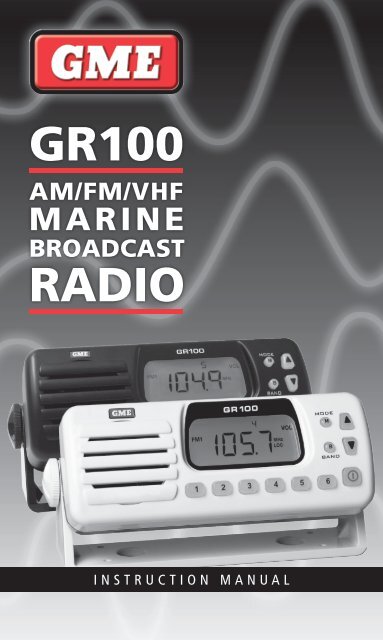
GR100<br />
AM/FM/VHF<br />
MARINE<br />
BROADCAST<br />
RADIO<br />
INSTRUCTION MANUAL
CONTENTS<br />
Features......................................................... 3<br />
ACCESSORIES...................................................... 3<br />
COMPLIANCE...................................................... 4<br />
Listening to FM in your Boat .. . . . . . . . . . . . . . . . . . . . . . . . . . . . . . . . . . . . . . 4<br />
LCD Display. ..................................................... 4<br />
Controls.. . . . . . . . . . . . . . . . . . . . . . . . . . . . . . . . . . . . . . . . . . . . . . . . . . . . . . . 5<br />
Power Key.. . . . . . . . . . . . . . . . . . . . . . . . . . . . . . . . . . . . . . . . . . . . . . . . . . . . 5<br />
Mode Key .. . . . . . . . . . . . . . . . . . . . . . . . . . . . . . . . . . . . . . . . . . . . . . . . . . . . 5<br />
Band Key...................................................... 5<br />
Up/Down Keys.................................................. 6<br />
Memory Keys................................................... 6<br />
Operation .. . . . . . . . . . . . . . . . . . . . . . . . . . . . . . . . . . . . . . . . . . . . . . . . . . . . . . 6<br />
Turning the GR100 On and Off..................................... 6<br />
Adjusting the Sound. . . . . . . . . . . . . . . . . . . . . . . . . . . . . . . . . . . . . . . . . . . . . 6<br />
Tuning for Stations. ............................................. 8<br />
Memory Keys................................................... 9<br />
Automatic Memory Storage.. . . . . . . . . . . . . . . . . . . . . . . . . . . . . . . . . . . . . . . 9<br />
Local/DX Mode .. . . . . . . . . . . . . . . . . . . . . . . . . . . . . . . . . . . . . . . . . . . . . . . 10<br />
Stereo/Mono Mode.. . . . . . . . . . . . . . . . . . . . . . . . . . . . . . . . . . . . . . . . . . . . 10<br />
Installation .. . . . . . . . . . . . . . . . . . . . . . . . . . . . . . . . . . . . . . . . . . . . . . . . . . . 10<br />
Mounting the GR100............................................ 11<br />
Electrical Wiring................................................ 12<br />
Specifications................................................... 14<br />
STANDARD COMMUNICATIONS CONTRACT WARRANTY. . . . . . . . . . . . . . . . . . . . 15<br />
BRANCH ADDRESSES .. . . . . . . . . . . . . . . . . . . . . . . . . . . . . . . . . . . . . . . BACK PAGE<br />
Page 2 <strong>Instruction</strong> <strong>Manual</strong> GR100
FEATURES<br />
• Compact design with bracket or flush mounting options<br />
• Ingress Protection to IP55*<br />
• 7 Bands (LW, SW, AM1, AM2, FM1, FM2, VHF)<br />
• 6 Preset Frequency memories per band<br />
• Simple Push button Controls.<br />
• Front panel ‘monitor’ speaker<br />
• Large amber backlit display with ‘Dim’ feature<br />
• FM stereo reception<br />
• Bass, treble and balance controls<br />
• Separate bass and treble memories for each band<br />
• Over voltage indicator<br />
• Reverse polarity protection<br />
• Static discharge protection at antenna input<br />
• User selectable VHF frequencies & NOAA Weather channels<br />
• Available in black or white<br />
Supplied<br />
accessories<br />
2 x Extension speaker leads - 3.5 mm mini jack<br />
Mounting bracket, gimbal knobs and Stainless Steel screws<br />
DC supply lead<br />
<strong>Instruction</strong> manual<br />
Optional<br />
In-dash flush mounting kits – MK100W (white), MK100B (black), MK002W, MK002B.<br />
Rear flush mount kit – MK600<br />
Choose from a range of <strong>GME</strong> antennas<br />
Choose from a range of <strong>GME</strong> speakers<br />
Cabin cover – CVR001 (white), CVR001B (black).<br />
*Refer: www.gme.net.au/IPRatings/IPRatings.html<br />
GR100<br />
<strong>Instruction</strong> <strong>Manual</strong><br />
Page 3
COMPLIANCE<br />
This device complies with AS/NZS 1053-CISPR13<br />
This device complies with part 15 of the FCC rules. Operation is subject to the<br />
condition that this device does not cause harmful interference.<br />
lISTENING TO FM IN YOUR BOAT<br />
The majority of FM broadcasts are music programs. Compared with AM signals, FM<br />
signals have a wider dynamic range, are relatively immune to noise and provide<br />
virtually distortion free music reproduction. However, because of the nature of FM<br />
signals and the fact that FM stations are usually positioned for shore based reception,<br />
reception in a moving boat may be accompanied by problems.<br />
FM programs are broadcast for local reception and may not be heard satisfactorily at<br />
distant locations. To enjoy FM programs at their best, it is important that you tune to a<br />
station that is broadcasting in your locality.<br />
FM signals can reflect from solid objects such as buildings or hills. If these reflected<br />
signals are received along with signals that are arriving directly from the transmitter,<br />
they may mix together to produce what is known as ‘multipath distortion’. This<br />
distortion is heard as noise. Often, moving as little as one metre from your position will<br />
correct this problem.<br />
FM signals travel in straight lines. Because the signals are reflected from or absorbed<br />
by large solid objects, a signal ‘shadow’ may be present behind the object which may<br />
result in poor reception in that area.<br />
LCD DISPLAY<br />
Weather Channels<br />
VHF Channels<br />
Memory number<br />
Band Selection<br />
Modes<br />
Frequency<br />
Page 4 <strong>Instruction</strong> <strong>Manual</strong> GR100
CONTROLS<br />
LCD Display<br />
Mode Key<br />
Band Key<br />
M<br />
B<br />
Up Key<br />
Down Key<br />
Speaker<br />
Memory Keys<br />
Power/Mute Key<br />
Power Key<br />
Press and hold the Power key to turn the GR100 ON or OFF. While the radio is ON,<br />
briefly press the Power key to toggle the audio mute button.<br />
Mode Key (M)<br />
The Mode Key provides access to the Volume, Bass, Treble, Balance, Frequency<br />
Adjustment, Automatic Memory Store (AMS) and Local/DX settings.<br />
The Mode selection will automatically return to the Volume setting 20 seconds after<br />
the last key press.<br />
Band Key (B)<br />
The GR100 has 7 selectable frequency bands labelled LW, SW, AM1, AM2, FM1, FM2<br />
and VHF. Each press of the BAND key cycles to the next band in sequence and a<br />
corresponding icon (LW, SW, AM1, AM2, FM1, FM2 or VHF) is displayed.<br />
The frequency coverage for each band is listed in the specifications at the rear of<br />
this manual.<br />
GR100<br />
<strong>Instruction</strong> <strong>Manual</strong><br />
Page 5
UP/Down Keys<br />
The Up and Down keys are used to adjust functions selected using the Mode key.<br />
Memory keys<br />
Six memory keys are provided for storage and retrieval of station memories.<br />
TURNING THE GR100 ON & OFF<br />
Operation<br />
To switch the GR100 on, press and hold the<br />
The radio will turn on.<br />
To switch the GR100 off, press and hold the<br />
The radio will turn off.<br />
key for two seconds.<br />
key for two seconds.<br />
Note: When the GR100 is switched off or the power is interrupted, it will remember<br />
the last state that it was set to and return to that state when it is switched back on.<br />
ADJUSTING THE SOUND<br />
Adjusting the Volume.<br />
During normal use, the GR100 will default to the Volume mode. Whenever the Volume<br />
mode is selected ‘VOL’ is displayed on the right of the LCD. If you are not in the<br />
Volume mode, briefly press the Mode key repeatedly until ‘VOL’ is displayed on<br />
the LCD.<br />
To adjust the Volume, press the or key. Pressing the key will increase the<br />
Volume while pressing the key will decrease the Volume. The volume setting will be<br />
displayed on the LCD. Minimum Volume setting displays a value of 0 with a maximum<br />
volume setting of 33. To quickly adjust the Volume setting, press and hold the<br />
or key.<br />
Adjusting the Bass<br />
To select the bass mode, briefly press the Mode key repeatedly until BASS is displayed<br />
on the right of the LCD. To adjust the bass, press the or key. Pressing the<br />
key will increase the bass while pressing the Key will decrease the bass. The bass<br />
setting will be displayed on the LCD. Minimum bass setting displays a value of -7 with<br />
a maximum bass setting of +7. A setting of 0 indicates a flat bass response. To quickly<br />
adjust the bass setting, press and hold the or key.<br />
Adjusting the Treble<br />
To select the treble mode, briefly press the Mode key repeatedly until ‘TRE’ is displayed<br />
on the right of the LCD. To adjust the treble, press the or key. Pressing the key<br />
Page 6 <strong>Instruction</strong> <strong>Manual</strong> GR100
will increase the treble while pressing the key will decrease the treble. The treble<br />
setting will be displayed on the LCD. Minimum treble setting displays a value of -7<br />
with a maximum treble setting of +7. A setting of 0 indicates a flat treble response. To<br />
quickly adjust the treble setting, press and hold the or key.<br />
Adjusting the Balance<br />
The balance setting controls the audio balance between the left and right speaker.<br />
Note: The balance mode is only available when the external speakers are attached. If<br />
running the GR100 from the internal monitor speaker, the balance function is skipped<br />
when the Mode key is pressed.<br />
Briefly press the Mode key repeatedly until ‘BAL’ is displayed on the right of the<br />
LCD. To adjust the Balance, press the or key. Pressing the key will adjust the<br />
balance towards the left speaker while pressing the Key will adjust the Balance<br />
towards the right speaker. The Balance setting will be displayed on the LCD. Full left<br />
balance displays a value of L10 with a full right balance setting of R10. A setting of<br />
0 indicates the balance is set equally between both speakers. To quickly adjust the<br />
Balance setting, press and hold the or key.<br />
Muting the Sound<br />
The Mute feature allows the radio’s sound to be temporarily disabled without affecting<br />
any other settings. This could be useful when making calls on your two way radio or<br />
mobile phone or during a local conversation where the radio sound is distracting.<br />
To temporarily mute the radio, briefly press the key. The audio will be temporarily<br />
disabled and no sound will be heard from the speaker(s). While the sound is muted,<br />
‘MUTE’ will flash on the display.<br />
To cancel the Mute selection and restore the sound to its previous level, briefly press<br />
the key again.<br />
Dimming the Display<br />
The display lighting can be dimmed for night time viewing. The default setting is<br />
maximum brightness. To dim the display:<br />
1. Press and hold the key to turn the GR100 OFF.<br />
2. Now press and hold the key again. The GR100 will turn on. DON’T RELEASE<br />
THE KEY YET.<br />
3. Now briefly press the M key to toggle the display lighting dim or bright. Once you<br />
have selected the display lighting you can release the key.<br />
GR100<br />
<strong>Instruction</strong> <strong>Manual</strong><br />
Page 7
TUNING FOR STATIONS<br />
Selecting the Frequency Band<br />
The GR100 has 7 selectable frequency bands labelled LW, SW, AM1, AM2, FM1, FM2<br />
and VHF. The two AM bands (AM1 and AM2) are identical to each other as are the two<br />
FM bands (FM1 and FM2).<br />
To select the required frequency band, briefly press the Band key. Each press will<br />
advance to the next band in sequence and a corresponding icon (LW1, SW, AM1, AM2,<br />
FM1, FM2 or VHF) will be displayed.<br />
Selecting USA or European Receiver Standards<br />
The GR100 supports both USA and European standards for AM and FM reception.<br />
Australian models conform to the European standard and are set that way by default.<br />
Owners in the USA should select the USA standard.<br />
To toggle between European or USA standards, press and hold the Band key for 3<br />
seconds. The GR100 will display ‘E’ at the top of the display for European or U for USA.<br />
The E or U will disappear when any of the preset memory buttons are pressed.<br />
The differences between European and USA bands and their frequency steps are listed<br />
in the specifications at the rear of this manual.<br />
Note: When the VHF marine band is selected, switching between USA and European<br />
standards will also select USA or International VHF marine channel allocations.<br />
<strong>Manual</strong>ly Tuning the Frequency<br />
Briefly press the Mode key repeatedly until ‘FREQ’ is displayed on the right hand side<br />
of the LCD. You can now manually change the frequency. To adjust the frequency,<br />
briefly press the or key. Pressing the key will increase the frequency while<br />
pressing the Key will decrease the frequency. The frequency will be displayed on the<br />
LCD.<br />
Scanning for Stations<br />
While in frequency tuning mode, press and hold the or key for 3 seconds. The<br />
GR100 will automatically scan upwards or downwards in frequency starting at the<br />
present frequency. When a station is found, scanning will stop on that frequency.<br />
Note: When tuning in the VHF band, standard VHF marine channel numbers 1-28 and<br />
60-88 are displayed. If the USA standard is selected, an additional ten NOAA weather<br />
channels are also available. When these are selected, ‘WEATHER’ is displayed on<br />
the LCD.<br />
Page 8 <strong>Instruction</strong> <strong>Manual</strong> GR100
MEMORY KEYS<br />
The GR100 has 6 preset memory keys which allow up to 6 frequencies to be stored<br />
and recalled within each band. Because there are two identical AM bands and two<br />
identical FM bands, this allows 12 AM and 12 FM preset memories. The memories can<br />
be stored either manually or automatically.<br />
<strong>Manual</strong>ly locating and storing station frequencies in the preset Memories<br />
1. Press the Band key repeatedly until the required band is selected.<br />
2. Press the Mode key repeatedly until the frequency adjustment mode is selected<br />
(‘Freq’ will be displayed).<br />
3. Press the or key briefly to manually step through the frequencies. To<br />
automatically scan for the next station, press and hold the or key.<br />
4. Once the required station has been located, press and hold one of the six memory<br />
keys for 3 seconds. The frequency will flash and the sound will mute briefly as the<br />
frequency is stored into the selected memory. The selected memory number will be<br />
displayed at the top of the LCD.<br />
Repeat steps 3 and 4 above to store other frequencies into the preset memories.<br />
Note: If a frequency or VHF marine channel is selected that is already stored in<br />
memory, the allocated memory number will also be displayed.<br />
Recalling stations from the preset Memories<br />
Select the required band, then briefly press the required memory button. The GR100<br />
will switch to the frequency stored in that memory location and the selected memory<br />
number will be displayed at the top of the LCD.<br />
AUTOMATIC MEMORY STORAGE (AMS)<br />
The AMS feature allows the GR100 to search the selected band for stations and<br />
automatically store the first six strongest stations it locates into the station memories.<br />
While activated, the Local (LOC) receiver sensitivity mode is temporarily selected to<br />
ensure only stronger local stations are selected.<br />
To activate the AMS feature, briefly press the Mode key repeatedly until ‘AMS’ is<br />
displayed on the lower right of the LCD. To begin the search, press the or key.<br />
Pressing the key will cause the GR100 to search upwards through the frequencies<br />
while pressing the key will cause it to search downwards. The search will begin from<br />
the last displayed frequency. As strong stations are found they will be automatically<br />
stored into the station memories. When all six memories have been filled, or the entire<br />
band has been searched, the search will stop and the station in Memory 1 is selected.<br />
To manually stop the memory search, briefly press the or key. To change the<br />
search direction, briefly press the opposite key after the search has been<br />
manually stopped.<br />
GR100<br />
<strong>Instruction</strong> <strong>Manual</strong><br />
Page 9
LOCAL/DX MODE<br />
The Local/DX mode controls the receiver’s sensitivity when in the FM mode. The GR100<br />
can be set to high sensitivity for long distance reception (DX) or low sensitivity for local<br />
reception (LOC).<br />
Briefly press the Mode key six times (one press past the AMS selection). The frequency<br />
will be displayed along with the LOC symbol. To select Local or DX modes, briefly press<br />
the or key. Each press will alternate between a solid LOC symbol (indicating Local<br />
mode is selected) and a flashing ‘LOC’ symbol (indicating DX mode is selected).<br />
When the GR100 returns to the normal display mode, a ‘LOC’ icon on the display<br />
indicates that local mode is selected. If ‘LOC’ is not visible, DX mode is selected.<br />
STEREO/MONO MODE<br />
The Stereo/Mono function can be selected on the FM band when the external stereo<br />
speakers are attached. If the GR100 is only operating from the internal monitor<br />
speaker, Mono/Stereo selection is not available.<br />
Mono<br />
Selecting Mono improves the quality of the reception when FM signals are weak or<br />
noisy by disabling stereo detection. When Mono is selected, there is no indication on<br />
the display<br />
Stereo<br />
Select stereo for normal stereo listening on the FM bands. When stereo is selected and<br />
a stereo signal is being received, ‘ST’ is displayed.<br />
To switch between Mono and Stereo modes, press and hold the Mode key for 3<br />
seconds. The ST icon will appear or disappear indicating the current selection.<br />
Rear Panel Connections<br />
INSTALLATION<br />
Antenna Socket<br />
Left Speaker Output<br />
DC Power<br />
Right Speaker Output<br />
Page 10 <strong>Instruction</strong> <strong>Manual</strong> GR100
Mounting the GR100<br />
The GR100 is designed to be mounted in several different ways to enable it to be<br />
installed in the most convenient position. The GR100 is designed to meet IP55<br />
Standard (Refer: www.gme.net.au/IPRatings/IPRatings.html). A location should be selected<br />
which provides the best viewing angle for the display. For best results select a location<br />
that is free from excessive vibration and continuous direct sunlight.<br />
Panel Mount Overhead Mount Upright Mount<br />
Upright or Overhead Mounting.<br />
Position the mounting bracket onto the GR100 so that the mounting holes in the<br />
bracket align with those on the side of the unit, and fit the gimbal knobs. Temporarily<br />
position the bracket in the desired location and roughly mark the bracket edges. Now<br />
remove the unit from the bracket and reposition the bracket to mark the mounting<br />
holes. Screw or bolt the bracket into position. The mounting method will depend on<br />
the surface to which the bracket is being attached. Refit the GR100 to the bracket and<br />
adjust the unit to the correct position before tightening the gimbal knobs.<br />
Complete the antenna lead and electrical wiring as described later.<br />
Flush Mounting<br />
If you require to flush mount your GR100 we recommend the MK100 flush mounting<br />
kit designed especially for the purpose. <strong>Instruction</strong>s and a mounting template are<br />
included with the kit.<br />
Panel<br />
Bracket<br />
GR100<br />
GR100<br />
<strong>Instruction</strong> <strong>Manual</strong><br />
Page 11
Electrical Wiring.<br />
The GR100 is suitable for either negative or positive ground systems.<br />
Note: The GR100 has an over voltage detector to indicate when excessive voltage is<br />
being applied to the radio. The over voltage detector is triggered when the voltage<br />
being applied to the power leads exceeds 18 Volts DC. If this happens, the words<br />
‘hi dc’ will flash on the display. If the voltage exceeds 21 Volts DC, the radio will<br />
automatically shut down.<br />
Referring to the wiring diagram<br />
1. Connect the RED fused wire directly to the positive terminal of the battery or to a<br />
point in the vessels electrical wiring that provides a +12 Volt connection.<br />
2. Connect the Black negative wire directly to the battery’s negative terminal or to a<br />
negative point in the vessels wiring.<br />
Speaker Connections<br />
Note: For simple installations, the GR100 can be used without external speakers if<br />
required. The GR100’s internal monitor speaker can provide good quality mono sound<br />
suitable for many applications. For full stereo sound you will need to connect a pair of<br />
external speakers. The GR100’s internal monitor speaker is automatically disconnected<br />
when the external speakers are plugged in.<br />
Page 12 <strong>Instruction</strong> <strong>Manual</strong> GR100
The GR100 is supplied with two speaker adapter leads which are designed to accept<br />
the standard bullet connectors found on some <strong>GME</strong> marine speakers and most marine<br />
and automotive speaker cables. The plugs on the speaker adapters plug into the<br />
matching the sockets on the rear of the GR100. The plugs are fitted with protective<br />
flexible covers.<br />
When connecting the speakers, observe the correct polarity as shown in the diagram.<br />
Incorrect polarity will result in a reduction of bass response and stereo effect. The use<br />
of speakers with an impedance of less than 4 ohms is not recommended as they will<br />
cause excessive loading of the GR100’s output circuit.<br />
The GR100 is a two speaker system that requires one pair of wires for each speaker.<br />
Avoid shorting the speaker wires together or touching them to the supply voltage or<br />
to ground.<br />
Once the GR100 is connected, you can adjust the balance between the left and right<br />
speaker using the Balance function.<br />
Antenna Connection<br />
The antenna should be mounted in a position as high as practical to ensure good<br />
reception especially in areas of low signal strength. When installing the antenna,<br />
ensure a minimum clearance of around 20 cm from bow or stern rails or windscreen<br />
frames etc. It is also recommended the antenna be placed at least one metre from<br />
two-way radio antennas to minimise interference from radio transmissions.<br />
To connect the antenna to your GR100, simply plug the antenna lead into the flying<br />
antenna socket on the rear of the unit.<br />
Waterproofing the connections<br />
After installation, the power, speaker and antenna connectors should be wrapped in<br />
waterproof tape or similar to minimise the risk of corrosion or water damage. Do not<br />
use normal electrical tape as this will not provide an adequate seal against water.<br />
The connectors should then be positioned where they are not directly exposed to the<br />
elements.<br />
Fuse Replacement<br />
If the fuse in the DC lead should blow, it should be replaced with a 2 Amp 3AG type.<br />
In the event of a failure, the use of a higher value fuse could result in damage to your<br />
GR100 which would void the warranty.<br />
GR100<br />
<strong>Instruction</strong> <strong>Manual</strong><br />
Page 13
specifications*<br />
General<br />
Complies with: AS<br />
Frequency Range: LW, MW, SW, VHF, AM and FM<br />
Channel Set: Broadcast Radio Bands<br />
Scan Speed: 100 ms/channel<br />
Supply Voltage Range: 10.8–15.6 V DC negative earth<br />
Current Protection: 2 A 3 AG fuse<br />
Reverse Polarity &<br />
Over Voltage Protection: ‘hi dc’ at 18 V shutdown at 21 V<br />
Receiver<br />
IF Frequencies: 1st: 10.7 MHz, 2nd: 450 kHz<br />
Modulation Frequency Response: 60 Hz–15 kHz for FM<br />
Adjacent Channel Rejection: > 73 dB<br />
Intermodulation Rejection: > 73 dB<br />
Blocking Rejection: > 90 dB<br />
Spurious Rejection: > 75 dB<br />
Audio Output Power: 4 Watts x 2 average into external 4 Ohms<br />
speaker. 2 Watts average into internal speaker.<br />
Audio S/N: > 45 dB<br />
Conducted Spurious Emission: < -70 dB<br />
Current Consumption: Full Volume: 1.2 A<br />
SENSITIVITY<br />
aM: -101 dBm 20 dB SINAD<br />
FM: -101 dBm 30 dB SINAD<br />
VHF: -105 dBm 12 dB SINAD<br />
mechanical<br />
Unit Dimensions: 164 (W) x 65 (H) x 58 (D) mm<br />
Unit Weight: 360 g approx.<br />
Flush Mounting Depth: 26 mm min.<br />
environmental<br />
Ingress Protection Rating: IP55 - Refer: www.gme.net.au/IPRatings/IPRatings.html<br />
Temperature Range: -10°C to +60°C<br />
Solar Radiation: Case UV stabilised<br />
Compass Safe Distance: 200 mm<br />
external connections<br />
DC Supply: 2 Pin polarised plug Socket<br />
External Speaker: 3.5 mm mini phone jack<br />
*All specifications are typical and subject to change without notice or obligation.<br />
Page 14 <strong>Instruction</strong> <strong>Manual</strong> GR100
Standard communications contract warranty<br />
1. Statutory Warranties<br />
1.1 The Trade Practices Act Part V, Division 2A<br />
and other legislation imply conditions,<br />
warranties and other obligations on us<br />
to consumers that cannot be excluded,<br />
restricted or modified. Those provisions<br />
apply to the extent required by law.<br />
1.2 We exclude all other conditions, warranties<br />
and obligations which would otherwise be<br />
implied concerning the activities covered<br />
by this agreement.<br />
1.3 We limit our liability where we are allowed<br />
to do so. Examples of where we are<br />
allowed to limit liability are -<br />
(a) you acquire goods from us for<br />
re-supply;<br />
(b) the goods or services we supply are<br />
not of a kind ordinarily acquired for<br />
personal, domestic or household use or<br />
consumption.<br />
1.4 Where we are allowed to limit our liability,<br />
to the extent permitted by law, our sole<br />
liability for breach of a condition, warranty<br />
or other obligation implied by law is<br />
limited -<br />
(a) in the case of goods we supply, to any<br />
one of the following as we decide -<br />
(i) the replacement of the goods or the<br />
supply of equivalent goods;<br />
(ii) the repair of the goods;<br />
(iii) the payment of the cost of<br />
repairing the goods or of acquiring<br />
equivalent goods;<br />
(iv) the payment of the cost of having<br />
the goods repaired; or<br />
(b) in the case of services we supply,<br />
to any one of the following as we<br />
decide -<br />
(i) the supplying of the services again;<br />
(ii) the payment of the cost of having<br />
the services supplied again.<br />
2. additional Warranties<br />
2.1 The warranties in this clause are in<br />
addition to the statutory warranties<br />
referred to in the previous clause.<br />
2.2 We warrant our goods to be free<br />
fromdefects in materials and workmanship<br />
for one year from the date of original sale<br />
(or another period we agree to in writing).<br />
During this period and as our sole liability<br />
to you under this warranty, we agree to,<br />
at our option, either repair or replace<br />
goods which we are satisfied are defective.<br />
We warrant replacement parts for the<br />
remainder of the period of warranty for the.<br />
goods into which they are incorporated.<br />
2.3 We warrant our other repairs to be<br />
free from defects in materials and<br />
workmanship for three months from the<br />
date of the original repair. During this<br />
period and as our sole liability to you for<br />
the repair, we agree to repair or replace (at<br />
our option) repaired goods which we are<br />
satisfied are defective.<br />
2.4 We warrant that we will perform services<br />
with reasonable care and skill and agree<br />
to investigate any complaint made in good<br />
faith that we have performed services<br />
unsatisfactorily. If we are satisfied that<br />
the complaint is justified, and as our sole<br />
liability to you under this warranty, we<br />
agree to supply those services again at no<br />
extra charge to you.<br />
2.5 If you want warranty service under this<br />
clause you must give us an original or copy<br />
of the sales invoice from the transaction<br />
or some other evidence showing details of<br />
the transaction.<br />
3. other limitations<br />
3.1 You may not rely on any representation,<br />
warranty or other provision by or for us<br />
which is not covered by clause [ 1 ] or<br />
repeated in this agreement in clear terms.<br />
3.2 We are not liable (nor are our employees,<br />
contractors and agents) for any damage,<br />
economic loss or loss of profits whether<br />
direct, indirect, general, special or<br />
consequential -<br />
(a) arising out of any breach of any implied<br />
or express term, condition or warranty;<br />
or<br />
(b) suffered as a result of our negligence<br />
(or that of our employees, contractors<br />
or agents)<br />
- apart from liability as set out in the<br />
previous two clauses.<br />
3.3 The liability of a party under this<br />
agreement (whether arising in contract,<br />
tort or by statute) is to be reduced by<br />
the same proportion as represents the<br />
proportion of the loss or damage caused<br />
or contributed to by the other party, its<br />
contractors or agents.<br />
GR100<br />
<strong>Instruction</strong> <strong>Manual</strong><br />
Page 15
A Division of: Standard Communications Pty. Ltd.<br />
Head Office: Sydney, Locked Bag 2086, North Ryde,<br />
N.S.W. 1670, Australia. T: +61 (0)2 9844 6666 F: +61 (0)2 9844 6600<br />
Branches:<br />
MELBOURNE, 7 Micro Circuit, DANDENONG STH 3165. T: (03) 9798 0988 F: (03) 9798 0177<br />
ADELAIDE, Unit 1, 14 Phillips St., THEBARTON 5031. T: (08) 8234 2633 F: (08) 8234 5138<br />
PERTH, Unit 1, 10-12 Harvard Way, CANNING VALE 6155. T: (08) 9455 5744 F: (08) 9455 3110<br />
BRISBANE, Unit 1, 89-101 Factory Rd., OXLEY 4075. T: (07) 3278 6444 F: (07) 3278 6555<br />
SYDNEY, Unit B, 22-24 College St., GLADESVILLE 2111. T: (02) 9879 8888 F: (02) 9816 4722<br />
AUCKLAND, Unit F, 35 Neilpark Drive, EAST TAMAKI 2141 NZ. T: (09) 274 0955 F: (09) 274 0959<br />
For customers outside Australia and New Zealand please contact your local <strong>GME</strong> retailer or email:<br />
export@gme.net.au<br />
Part No. 310195 Drawing. No.: 41780-6


