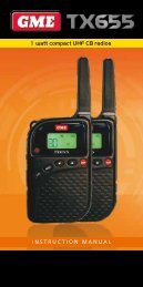
INSTRUCTION MANUAL Super compact 5 Watt 80 Channel ... - GME
INSTRUCTION MANUAL Super compact 5 Watt 80 Channel ... - GME
INSTRUCTION MANUAL Super compact 5 Watt 80 Channel ... - GME
- No tags were found...
Create successful ePaper yourself
Turn your PDF publications into a flip-book with our unique Google optimized e-Paper software.
CONTENTSIntroduction..........................................................................3IMPORTANT INFORMATION........................................................3Telemetry <strong>Channel</strong>s..............................................................4Features...................................................................................5General Operation................................................................6Unique Flip Feature.............................................................7Power.................................................................................7Volume...............................................................................7Selecting <strong>Channel</strong>s..............................................................7Transmitting........................................................................7Squelch Control..................................................................8Squelch Sensitivity...............................................................8Backlight............................................................................9Duplex Operation................................................................9Dynamic Volume Control.....................................................9Adjusting the Beep Tone Level...........................................11CTCSS & DCS............................................................................11Selecting the CTCSS or DCS Tone.......................................12Enabling CTSS/DCS on a <strong>Channel</strong>......................................13Disabling CTCSS/DCS on a <strong>Channel</strong>...................................13Monitoring the <strong>Channel</strong>....................................................13Scanning...............................................................................14Programming Scan <strong>Channel</strong>s.............................................14Using Scan...............................................................................14Skipping Over Busy <strong>Channel</strong>s While Scanning............................15Transmitting While Scanning.....................................................15Installation..........................................................................15Antenna Installation..........................................................16Noise Suppression.............................................................16DC Power Connection.......................................................19High Voltage Detection......................................................20Antenna Connection.........................................................20UHF CB Operating Frequencies...........................................21CTCSS Tone Frequency chart.............................................22DCS Tone chart.....................................................................23specifications.......................................................................24SC contract Warranty.......................................................26<strong>GME</strong> After Sales Service.....................................................27Accessories supplied• Main Radio Unit• Screw Pack• Mounting Cradle • Supplementary <strong>GME</strong>model label• Instruction ManualIf any items are missing or• Microphonedamaged, please contact your• Microphone Clip retailer or place of purchase.• DC LeadPA G E 2 i n s t r u c t i o n m a n ua l t X 3 1 0 0
Basic ControlsGeneral operationMicrophone SocketPower<strong>Channel</strong>TX3100SLCDVolumeScanSquelchLCDTransmitSquelch IconScan IconSilent (CTCSS) IconSDCS Icon<strong>Channel</strong> DisplayPA G E 6 i n s t r u c t i o n m a n ua l t X 3 1 0 0
MicrophonePush-To-Talk (PTT)POWERTo turn the TX3100 ON, briefly press the key.To turn the TX3100 OFF, press and hold the key.VOLUMEPress the or keys to increase or decrease the volume. Theradio will beep with each key press and the display will flashto indicate the volume setting is being displayed. The volumelevel can be set from 00 (min) to 31 (max). The display will stopflashing and will return to displaying the selected channel a fewseconds after the last volume adjustment.NOTE: At the minimum volume setting there is still sufficientvolume to be heard in a quiet cabin environment.Selecting <strong>Channel</strong>sUnique Flip FeatureThe TX3100 has a unique Display Flip function that allows theunit to be installed upside down, if required, and the display readfrom either orientation.For more information on this feature please refer to Flipping theDisplay under Installation on page 18.Press the or keys to step upwards or step downwardsthrough the channels.TransmittingTo transmit, press the PTT button. Hold the microphone about5-8 cm from your face and speak at a normal voice level. Themicrophone is quite sensitive so it is not necessary to raise yourvoice or shout. Release the PTT when you have finished talking.IMPORTANT: Always listen to ensure the channel is freebefore transmitting.T X 3 1 0 0 i n s t r u c t i o n m a n ua l PA G E 7
<strong>Channel</strong> Selected Receive <strong>Channel</strong> Transmit <strong>Channel</strong>1 1 312 2 323 3 334 4 345* 5* 35*6 6 367 7 378 8 3841 41 7142 42 7243 43 7344 44 7445 45 7546 46 7647 47 7748 48 78* Emergency <strong>Channel</strong> onlyThe TX3100 allows you to select Duplex operationindividually on each channel.To select Duplex on individual channels;1. Select the required channel (1 – 8 or 41 – 48).2. Press and hold the key and immediately press thekey. The ‘0’ in the channel number will change to ‘r’ ifchannel 1 – 8 is selected to indicate that channel is now setas a repeater channel. The ‘0’ in the channel will change to’u’ to indicate the channel is now set as an upper repeaterchannel, if channel 41 – 48 is selected.Eg: <strong>Channel</strong> 2 will be displayed as ‘02’ S when in simplex modebut will change to ‘r2’ when duplex is activated on that channel.<strong>Channel</strong> 42 will be displayed as ‘42’ when in simplex mode butwill change to ‘u2’ when duplex is activated on that channel.<strong>Channel</strong> 2 Simplex<strong>Channel</strong> 2 Duplex (repeater)<strong>Channel</strong> 42 Duplex (repeater)SSPA G E 1 0 i n s t r u c t i o n m a n ua l t X 3 1 0 0
NOTE: You must press the key immediately after pressing thekey otherwise the scan memory function will be activated.See Scanning on page 14.Adjusting the Beep Tone LevelThe beep tones on your TX3100 are designed to provide audiblefeedback whenever a key is pressed. If the beep tone level is tooloud or too soft for your operating environment you can adjust itas follows:1. Turn the TX3100 OFF.2. Hold either the or key while turning the radio ON.3. A number will flash on the display to indicate the currentbeep tone level setting.4. Within 3 seconds, press the or keys to increase ordecrease the beep tone level. The maximum level is 9 and theminimum audible level is 1. To turn the beep tone off set thelevel to 0.5. To return the radio to normal operation, press any other key orsimply wait 3 seconds.CTCSS & DCSCTCSS (Continuous Tone Coded Squelch System) and DCS(Digitally Coded Squelch) are Squelch quieting systems thatallow several groups of users to share the same channel withoutdisturbing each other. The system applies a continuous low-leveltone to your transmission and uses a matching tone decoder tocontrol your receiver’s Squelch. With CTCSS or DCS enabled, thechannel remains quiet to all incoming signals unless they carrythe correct tone. When a transmission with the correct tone isreceived, the Squelch opens and remains open for as long asthe signal is present. When the transmission ends, the channelbecomes quiet again. Transmissions that do not use the correcttone will not be heard.There are two tone sets installed in your TX3100, compromising50 CTCSS and 104 DCS user-selectable tones.The TX3100 allows CTCSS or DCS to be enabled or disabled onindividual channels.NOTE: The CTCSS/DCS tone you select will be used for allCTCSS/DCS enabled channels in your radio.T X 3 1 0 0 i n s t r u c t i o n m a n ua l PA G E 1 1
Selecting the CTCSS or DCS ToneChoosing which tone to use will probably be dependent on theother radios you talk to. If you talk to others outside your groupwho already use CTCSS or DCS tones you will need to select thetone set that matches theirs. The TX3100 includes most of thecommonly used tone sets.If the users you talk to don’t currently use CTCSS or DCS you canmake your own choice. There is no difference in performancebetween the two tone sets.NOTE: When selecting tones please refer to the CTCSS andDCS Tone Charts on pages 22 – 23.SCTCSS Off3. Press the or keys to select the required CTCSS tone.The flashing ‘S’ indicates the tones you are selecting areCTCSS tones.The CTCSS and DCS tones are stored in your radio in a sequentialtable. The first table location is OFF. The next 50 locations areCTCSS tones followed by 104 DCS tones.SCTCSS Tone 24OFF CTCSS 01 to CTCSS 50 DCS 01 to DCS 104To select a tone1. Switch the TX3100 off.2. Press and hold the key while switching the radio on.‘S’ flashes and the channel number displays the currentlyselected tone. If OF is displayed the tones are set to OFF.4. If you advance past CTCSS tone 50 the tone number resets to01 and the symbol flashes indicating that you are nowselecting DCS tones. Continue advancing through the tones toselect your required DCS tone.SPA G E 1 2 i n s t r u c t i o n m a n ua l t X 3 1 0 0
NOTE: Since the display does not have enough digits to displayDCS tones 100 - 104, these tones are displayed as A0 - A4.5. Once the required CTCSS or DCS tone is selected, briefly pressthe key to exit the tone setting mode. The selected tonewill now be used on any channels where the Silent modeis enabled.Enabling CTCSS/DCS on a <strong>Channel</strong>Once a CTCSS/DCS tone has been selected, it can be enabled onindividual channels.1. Press the or keys to select the required channel.2. Press and hold the key. A high beep will be heard and‘S’ will appear on the display. If a DCS tone is being used,will also be displayed.Your radio is now in ‘Silent’ mode and will remain muted on thatchannel unless a signal containing your selected CTCSS/DCS toneis received. <strong>Channel</strong>s that do not have CTCSS/DCS enabled willremain open to all signals.You may activate CTCSS/DCS on as many channels as you wishexcept channel 5 which is designated for emergency use.NOTE: CTCSS/DCS may not work through some repeaters.Disabling CTCSS/DCS on a <strong>Channel</strong>Repeat steps 1 and 2 above. A low beep will be heard and ‘S’will disappear from the display.NOTE: You will not be able to activate CTCSS/DCS on anychannel if the CTCSS/DCS tone is set to ‘OF’.Monitoring the <strong>Channel</strong>It is useful to be able to temporarily open your radio’s Squelchto allow you to listen for signals from other CTCSS/DCS usersoutside your group. Because their CTCSS/DCS tone is differentto yours, your Squelch would normally remain closed, preventingyou from hearing them. You can use the key to openthe Squelch and listen to the channel to check that it is clearbefore transmitting. This will help prevent you from accidentallytransmitting over the top of others.To monitor the channelBriefly press the key. If there are no signals present, you willhear the usual hiss of an empty channel. Press the key againto restore the Squelch to its previous setting.T X 3 1 0 0 i n s t r u c t i o n m a n ua l PA G E 1 3
SCANNINGThe TX3100 has a SCAN function that allows a selection of userprogrammable channels to be scanned for signals. <strong>Channel</strong>sare scanned at 20 channels per second. When a signal is found,scanning will pause on that channel to allow the signal to beheard, then resume scanning when the channel is clear again.Programming Scan <strong>Channel</strong>sYour TX3100 is supplied with all <strong>80</strong> UHF CB channelsprogrammed into the Scan memory. Any channels not needed,can be removed if required.To add or remove channels from the scan memory1. Ensure that the radio is not already scanning. If it is, brieflypress the key to cancel the scan function.2. Select the required channel by using the or keys• If is visible on the display, the selected channel isalready in the scan memory.• If is not visible, then the selected channel is not inthe memory.• To add or remove the selected channel, press and hold thekey for a few seconds until a beep is heard.3. Repeat step 2 to add or remove other channels in thescan memory.To start scanningTo begin scanning, briefly press the key. A high beep willbe heard, will flash on the display and the radio willbegin scanning.NOTE: If there is only one channel programmed into the Scanmemory, a long low beep will be heard when you press thekey and the command will be ignored.To stop scanningTo cancel the scan, briefly press the key. A low beep willbe heard and will stop flashing on the display.Using Scan• If a busy channel is found, scanning will pause on that channelto allow the signal to be heard and will remain there for aslong as the channel remains busy. Once the channel has beenclear for 5 seconds, scanning will resume automatically.• If your radio is paused on a busy channel and you wish toremain there, briefly press the key. The radio will exitScan mode and remain on the busy channel.• If the radio pauses on a busy channel and you don’t wishto listen to the conversation briefly press either of the orkeys. The radio will skip over that channel and resumescanning from the next channel in the sequence.PA G E 1 4 i n s t r u c t i o n m a n ua l t X 3 1 0 0
Skipping Over Busy <strong>Channel</strong>s While ScanningWhen scanning, if the radio pauses on a busy channel and youdon’t wish to listen to the conversation briefly press either of theor keys. The radio will skip over that channel and resumescanning from the next channel in the sequence.Transmitting while scanningWhen scanning, your radio remembers the last channel on whichit transmitted and will automatically return to that channel eachtime the PTT is pressed.Before scanning, you can define your initial transmit channel bypreselecting that channel first before you press the key.Once scanning has commenced, pressing the PTT will pause thescan and your radio will transmit on the preselected channel. Ifthere is no activity on the channel after 5 seconds thescan resumes.• If scanning pauses on a (different) busy channel and you pressthe PTT during this time, the busy channel becomes your newdefault transmit channel. If there is no activity on the channelafter 5 seconds the scan resumes but subsequent presses ofthe PTT will return you to this new channel. This allows you tocontinue to use this channel even if pauses in the conversationexceed the 5 second timeout period.• If the radio stops on another busy channel then restartswithout the PTT being pressed, your default transmit channelwon’t change.INSTALLATIONThe TX3100 is supplied with a slim, U-shaped mounting cradle.The cradle can be screwed or bolted in any convenient locationin your vehicle (under or above the dash, on the centre console,etc.) using the mounting slots provided in the cradle. TheTX3100 contains a built-in speaker and should be installed in alocation where the sound can be heard from the driver’s position.Alternatively it can be installed in a less audible location and anextension speaker used instead.The microphone comes complete with a mounting clip. Its lightweight design allows it to be mounted in almost any convenientposition accessible to the driver.When installing the radio, avoid mounting it close to heaters orair conditioners. Screw the microphone’s clip to a firm surface. Fitthe TX3100 into the cradle and tighten the gimbal knobs. Placethe microphone in its mounting clip. Finally, plug the microphoneinto the front panel of the TX3100 and the power and antennaleads into the sockets provided on the rear of the radio.T X 3 1 0 0 i n s t r u c t i o n m a n ua l PA G E 1 5
Antenna InstallationIt is essential to select a good quality, high efficiency, 477 MHzantenna. A poor quality antenna or one not designed for thespecific frequency band you are using will give verypoor performance.<strong>GME</strong> have a wide range of suitable 477 MHz UHF CB antennasto suit most installations and applications. We recommendcontacting your local <strong>GME</strong> retailer for advice.Connect the antenna cable to the rear antenna socket using aPL259 coaxial connector.Fitting the MicrophoneSlide Microphoneinto the mounting clipNoise SuppressionThe inherent design of FM transceivers result in a high level ofresistance to ignition and electrical interference. However insome installations it may be necessary to take additional steps tohelp reduce or eliminate noise interference. During installation,try to route the DC battery leads, the antenna lead or anyaccessory wires away from the engine compartment, ignition oralternator wiring. If the noise continues, it may be necessary tofit a suppression kit in which case we recommend you consult anauto electrician for advice specific to your installation.Higher frequency electrical interference caused by electric motorscan be suppressed directly at the motor terminals.Mounting the CradlePA G E 1 6 i n s t r u c t i o n m a n ua l t X 3 1 0 0
TX3100Fitting the RadioFit radio into cradle and tighten gimbal knobs.58 mmLabel31 mmThe mounting bracket can be oriented with the arms extendingeither forward or backwards to adjust the position of the frontpanel with reference to the mounting point.Your TX3100 is fitted with a <strong>GME</strong> model label adjacent tothe LCD. If the final orientation of your radio results in thislabel being upside down, please fit the supplementary <strong>GME</strong>label supplied. Simply remove the backing tape and install thesupplementary label over the top of the current <strong>GME</strong> label.T X 3 1 0 0 i n s t r u c t i o n m a n ua l PA G E 1 7
Connecting the MicrophoneThe microphone uses a 6 pin plug and socket. To connect:1. Position the microphone plug in the socket so the plastic tabfaces away from the speaker, and press the plug into thesocket until it ‘clicks’.2. Gently slide the rubber boat towards the hole surrounding thesocket and press into place until it locks into the front panel.Removing the Microphone1. Slide the rubber boot back along the microphone cord.2. Squeeze the plastic tab on the microphone plug towards theplug to unlock it while gently pulling the plug outwards. Ifthe plug does not come out easily, the tab has not releasedcorrectly and should be squeezed again.CableSpeakerPlastic tabScrewdriverLocking levermove left torelease plugCable entryholeFlipping the DisplayThe TX3100’s small size allows it to be mounted in almost anyconvenient location. However the most suitable location maysometimes require the unit to be installed upside-down whenreferenced to your driving position.The TX3100 is designed to overcome this situation by allowingthe display to be ‘flipped’. In addition the keys have symbolsthat can be read from either direction.You can flip the display as follows.With the unit installed or held in the required orientation;1. Turn the unit off.2. Press and hold the key while turning the radio on.3. The display will be flip to match the radio’s orientation.Front Panel Upright (speaker above)TX3100SFront Panel Flipped (speaker below)STX3100PA G E 1 8 i n s t r u c t i o n m a n ua l t X 3 1 0 0
DC POWER CONNECTIONThe TX3100 is designed for 13.8 volts DC, negative earthinstallations only (i.e. where the negative terminal of the batteryis connected to the chassis or frame of the vehicle).There are two recommended methods of installation.Radio remains ON when the ignition switch is OFFConnect the radio's negative (black) lead to the vehicle's chassis,or if preferred, directly to the battery's negative terminal.The radio's positive (red) lead should be connected via the 2amp fuse to the battery's positive terminal. Alternatively, thepositive lead could be connected into the fuse box at a point thathas +13.8 volts continuously available (the battery side of theignition switch) via the 2 amp fuse.Radio turns OFF with the ignition switch:Connect the radio's negative (black) lead to the vehicle's chassis,or if preferred, directly to the battery's negative terminal.The radio's positive (red) lead should connect to an accessorypoint in the vehicle's fuse box via the 2 amp fuse. This pointshould supply +13.8 volts only when the ignition switch is turnedON or in the ACCESSORY position.RadioRadioremainsremainsONONwhenwhenignitionignitionswitchswitchisisOFFOFFREDREDToTX3100BLACKBLACKChassisChassisCar batteryCar batteryIngnition SwitchIngnition SwitchRadioRadioturnsturnsONONandandOFFOFFwithwithignitionignitionswitchswitchREDREDToTX3100BLACKBLACKChassisChassisCar batteryCar batteryIngnition SwitchIngnition SwitchT X 3 1 0 0 i n s t r u c t i o n m a n ua l PA G E 1 9
UHF CB Operating Frequencies<strong>Channel</strong> Frequency (MHz) <strong>Channel</strong> Frequency (MHz) <strong>Channel</strong> Frequency (MHz) <strong>Channel</strong> Frequency (MHz)1 476.425 ~ 21 476.925 41 476.4375 ~ 61 • 476.93752 476.450 ~ 22 # 476.950 42 476.4625 ~ 62 • 476.96253 476.475 ~ 23 # 476.975 43 476.4875 ~ 63 • 476.98754 476.500 ~ 24 477.000 44 476.5125 ~ 64 477.01255* 476.525 ~ 25 477.025 45 476.5375 ~ 65 477.03756 476.550 ~ 26 477.050 46 476.5625 ~ 66 477.06257 476.575 ~ 27 477.075 47 476.5875 ~ 67 477.08758 476.600 ~ 28 477.100 48 476.6125 ~ 68 477.11259 476.625 29 477.125 49 476.6375 69 477.137510 476.650 30 477.150 50 476.6625 70 477.162511 + 476.675 31 477.175 ~ 51 476.6875 71 477.1875 ~12 476.700 32 477.200 ~ 52 476.7125 72 477.2125 ~13 476.725 33 477.225 ~ 53 476.7375 73 477. 2375 ~14 476.750 34 477.250 ~ 54 476.7625 74 477.2625 ~15 476.775 35* 477.275 ~ 55 476.7875 75 477.2875 ~16 476.<strong>80</strong>0 36 477.300 ~ 56 476.8125 76 477.3125 ~17 476.825 37 477.325 ~ 57 476.8375 77 477.3375 ~18 476.850 38 477.350 ~ 58 476.8625 78 477.3625 ~19 476.875 39 477.375 59 476.8875 79 477.387520 476.900 40^ 477.400 60 475.9125 <strong>80</strong> 477.4125T X 3 1 0 0 i n s t r u c t i o n m a n ua l PA G E 2 1
50 ToneSetFrequency50 ToneSetCTCSS Tone frequency chartFrequency50 ToneSetFrequency50 ToneSetFrequency50 ToneSetFrequency1 67.0 11 94.8 21 131.8 31 171.3 41 203.52 69.4 12 97.4 22 136.5 32 173.8 42 206.53 71.9 13 100.0 23 141.3 33 177.3 43 210.74 74.4 14 103.5 24 146.2 34 179.9 44 218.15 77.0 15 107.2 25 151.4 35 183.5 45 225.76 79.7 16 110.9 26 156.7 36 186.2 46 229.17 82.5 17 114.8 27 159.8 37 189.9 47 233.68 85.4 18 118.8 28 162.2 38 192.8 48 241.89 88.5 19 123.0 29 165.5 39 196.6 49 250.310 91.5 20 127.3 30 167.9 40 199.5 50 254.1CTCSS Frequency shown in HzPA G E 2 2 i n s t r u c t i o n m a n ua l t X 3 1 0 0
DCS TONE chartDCS CODE DCS CODE DCS CODE DCS CODE DCS CODE DCS CODE1 023 19 116 37 225 55 325 73 452 91 6272 025 20 122 38 226 56 331 74 454 92 6313 026 21 125 39 243 57 332 75 455 93 6324 031 22 131 40 244 58 343 76 462 94 6545 032 23 132 41 245 59 346 77 464 95 6626 036 24 134 42 246 60 351 78 465 96 6647 043 25 143 43 251 61 356 79 466 97 7038 047 26 145 44 252 62 364 <strong>80</strong> 503 98 7129 051 27 152 45 255 63 365 81 506 99 72310 053 28 155 46 261 64 371 82 516 A0 73111 054 29 156 47 263 65 411 83 523 A1 73212 065 30 162 48 265 66 412 84 526 A2 73413 071 31 165 49 266 67 413 85 532 A3 74314 072 32 172 50 271 68 423 86 546 A4 75415 073 33 174 51 274 69 431 87 56516 074 34 205 52 306 70 432 88 60617 114 35 212 53 311 71 445 89 61218 115 36 223 54 315 72 446 90 624T X 3 1 0 0 i n s t r u c t i o n m a n ua l PA G E 2 3
Specifications*ENVIRONMENTALTemperature Range: -10°C to +60°CELECTRICALGeneralCompliant Specification: AS/NZS 4365Frequency Range: 476.425-477.4125 MHzNumber of <strong>Channel</strong>s: <strong>80</strong> UHF CB<strong>Channel</strong> Spacing: 12.5 kHzOperation Mode: Simplex channels 1-<strong>80</strong>semi Duplex channels 1‐8, 41-48.Scanning Speed: 20 channels per secondAntenna Impedance: 50 Ohms nominalOperating Voltage Range: 10-15 volts DCNominal Battery Voltage: 13.8 volts DCOver Voltage Protection: 25 volts DC max. At 18 volts DC theRF power is reduced, and the words‘Hi DC’ flash.Over Current Protection: In-line 2A FuseReverse Polarity Protection: Shunt DiodeFrequency Stability: ±2.5 PPMTransmitterrF Output: 5.0 watts max.modulation: FMMaximum Deviation: < ± 2.5 kHz at + 20 dB limitingSpurious Emissions: < - 70 dBcTransmit Frequencyresponse: + 6 dB per octave300 Hz to 3 kHz + 1-3 dB.Audio Signal to Noise: > 45 dBCurrent Consumption: 1.5 amps with 50 Ohms termination*Specifications are typical unless otherwise indicated and may be subject to change without notice or obligation.PA G E 2 4 i n s t r u c t i o n m a n ua l t X 3 1 0 0
Receivercircuit Type: Double Conversion<strong>Super</strong>heterodyneIntermediate Frequencies: 1st - 38.85 MHz2nd - 450 kHzCurrent Consumption: < 1<strong>80</strong> mA muted600 mA @ max. A.F outputsensitivity: - 123 dBm for 12 dB SINADunweightedselectivity: - 6 dB at + 3.5 kHz‐ 60 dB at ± 12.5 kHzIntermodulation Immunity: 73 dBBlocking Immunity: 100 dBSpurious Responseimmunity: 70 dBAudio Power: 3 watts average into 4 OhmsAudio Signal to Noise: > 45 dBReceive Frequencyresponse: ‐ 6 dB/Octave de‐emphasis300 Hz to 3 kHz + 1-3 dBConducted SpuriousEmission: < - 57 dBmMECHANICALDimensions: 102 (W) x 87 (D) x 23 (H) mmWeight: 158 gramsShock and Vibration: MIL STD 810 methodT X 3 1 0 0 i n s t r u c t i o n m a n ua l PA G E 2 5
Standard communications contract warranty1. Statutory Warranties1.1 The Trade Practices Act Part V, Division 2A and otherlegislation imply conditions, warranties and other obligationson us to consumers that cannot be excluded, restricted ormodified. Those provisions apply to the extent required bylaw.1.2 We exclude all other conditions, warranties and obligationswhich would otherwise be implied concerning the activitiescovered by this agreement.1.3 We limit our liability where we are allowed to do so.Examples of where we are allowed to limit liability are -(a) you acquire goods from us for re-supply;(b) the goods or services we supply are not of a kindordinarily acquired for personal, domestic or householduse or consumption.1.4 Where we are allowed to limit our liability, to the extentpermitted by law, our sole liability for breach of a condition,warranty or other obligation implied by law is limited -(a) in the case of goods we supply, to any one of thefollowing as we decide -(i) the replacement of the goods or the supply ofequivalent goods;(ii) the repair of the goods;(iii) the payment of the cost of repairing the goods or ofacquiring equivalent goods;(iv) the payment of the cost of having the goodsrepaired; or(b) in the case of services we supply, to any one of thefollowing as we decide -(i) the supplying of the services again;(ii) the payment of the cost of having the servicessupplied again.2. additional Warranties2.1 The warranties in this clause are in addition to the statutorywarranties referred to in the previous clause.2.2 We warrant our goods to be free from defects in materialsand workmanship for three years from the date of originalsale (or another period we agree to in writing). During thisperiod and as our sole liability to you under this warranty, weagree to, at our option, either repair or replace goods whichwe are satisfied are defective. We warrant replacement partsfor the remainder of the period of warranty for the goods intowhich they are incorporated.2.3 We warrant our other repairs to be free from defects inmaterials and workmanship for three months from the dateof the original repair. During this period and as our soleliability to you for the repair, we agree to repair or replace (atour option) repaired goods which we are satisfiedare defective.2.4 We warrant that we will perform services with reasonablecare and skill and agree to investigate any complaint made ingood faith that we have performed services unsatisfactorily.If we are satisfied that the complaint is justified, and as ourPA G E 2 6 i n s t r u c t i o n m a n ua l t X 3 1 0 0
sole liability to you under this warranty, we agree to supplythose services again at no extra charge to you.2.5 If you want warranty service under this clause you mustgive us an original or copy of the sales invoice from thetransaction or some other evidence showing details ofthe transaction.3. other limitations3.1 You may not rely on any representation, warranty or otherprovision by or for us which is not covered by clause [ 1 ] orrepeated in this agreement in clear terms.3.2 We are not liable (nor are our employees, contractors andagents) for any damage, economic loss or loss of profitswhether direct, indirect, general, special or consequential -(a) arising out of any breach of any implied or expressterm, condition or warranty; or(b) suffered as a result of our negligence (or that of ouremployees, contractors or agents) - apart fromliability as set out in the previous two clauses.3.3 The liability of a party under this agreement (whetherarising in contract, tort or by statute) is to be reduced bythe same proportion as represents the proportion of the lossor damage caused or contributed to by the other party, itscontractors or agents.<strong>GME</strong> after sales serviceYour <strong>GME</strong> TX3100 is especially designed for the environmentencountered in mobile applications. The use of all solid statecircuitry, careful design and rigorous testing, result in highreliability. Should failure occur however, <strong>GME</strong> maintain a fullyequipped service facility and spare parts stock to meet thecustomer’s requirements long after expiry of the warranty period.T X 3 1 0 0 i n s t r u c t i o n m a n ua l PA G E 2 7
For customers outside Australia and New Zealand, please contact your local <strong>GME</strong> retailer or email to: export@gme.net.auwww.gme.net.auPart Number: 310520 Drawing Number: 45455-2A division of:Standard Communications Pty. Ltd.Head Office: SYDNEY- Locked Bag 2086, North Ryde NSW 1670, Australia. Tel: (02) 9844 6666, Fax: (02) 9844 6600.Melbourne Adelaide Perth Brisbane Sydney Auckland7 Micro Circuit 14 Phillips St. Unit 1 Unit 1 Unit B 2/24 Bishop Dunn PlaceDandenong South Thebarton 10-12 Harvard Way 89-101 Factory Rd. 22-24 College St. East TamakiVIC 3165 SA 5031 Canning Vale Oxley Gladesville Manukau 2013T: (03) 9798 0988 T: (08) 8234 2633 WA 6155 QLD 4075 NSW 2111 NZF: (03) 9798 0177 F: (08) 8234 5138 T: (08) 9455 5744 T: (07) 3278 6444 T: (02) 9879 8888 T: (09) 274 0955F: (08) 9455 3110 F: (07) 3278 6555 F: (02) 9816 4722 F: (09) 274 0959


