Computer Science 281 Lab 1: Logisim Basics
Computer Science 281 Lab 1: Logisim Basics
Computer Science 281 Lab 1: Logisim Basics

You also want an ePaper? Increase the reach of your titles
YUMPU automatically turns print PDFs into web optimized ePapers that Google loves.
<strong>Computer</strong> <strong>Science</strong> <strong>281</strong><br />
<strong>Lab</strong> 1: <strong>Logisim</strong> <strong>Basics</strong><br />
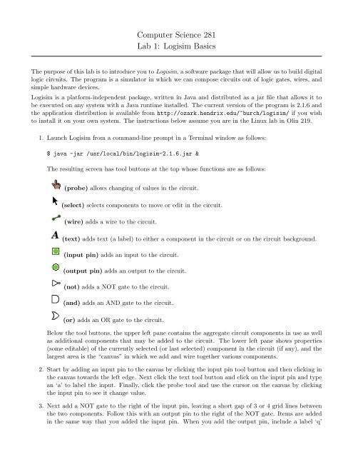
The purpose of this lab is to introduce you to <strong>Logisim</strong>, a software package that will allow us to build digital<br />
logic circuits. The program is a simulator in which we can compose circuits out of logic gates, wires, and<br />
simple hardware devices.<br />
<strong>Logisim</strong> is a platform-independent package, written in Java and distributed as a jar file that allows it to<br />
be executed on any system with a Java runtime installed. The current version of the program is 2.1.6 and<br />
the application distribution is available from http://ozark.hendrix.edu/~burch/logisim/ if you wish<br />
to install it on your own system. The instructions below assume you are in the Linux lab in Olin 219.<br />
1. Launch <strong>Logisim</strong> from a command-line prompt in a Terminal window as follows:<br />
$ java -jar /usr/local/bin/logisim-2.1.6.jar &<br />
The resulting screen has tool buttons at the top whose functions are as follows:<br />
(probe) allows changing of values in the circuit.<br />
(select) selects components to move or edit in the circuit.<br />
(wire) adds a wire to the circuit.<br />
(text) adds text (a label) to either a component in the circuit or on the circuit background.<br />
(input pin) adds an input to the circuit.<br />
(output pin) adds an output to the circuit.<br />
(not) adds a NOT gate to the circuit.<br />
(and) adds an AND gate to the circuit.<br />
(or) adds an OR gate to the circuit.<br />
Below the tool buttons, the upper left pane contains the aggregate circuit components in use as well<br />
as additional components that may be added to the circuit. The lower left pane shows properties<br />
(some editable) of the currently selected (or last selected) component in the circuit (if any), and the<br />
largest area is the “canvas” in which we add and wire together various components.<br />
2. Start by adding an input pin to the canvas by clicking the input pin tool button and then clicking in<br />
the canvas towards the left edge. Next click the text tool button and click on the input pin and type<br />
an ‘a’ to label the input. Finally, click the probe tool and use the cursor on the canvas by clicking<br />
the input pin to see it change value.<br />
3. Next add a NOT gate to the right of the input pin, leaving a short gap of 3 or 4 grid lines between<br />
the two components. Follow this with an output pin to the right of the NOT gate. Items are added<br />
in the same way that you added the input pin. When you add the output pin, include a label ‘q’
for the pin. Finally wire together the input pin to the NOT gate input and the output of the NOT<br />
gate to the output pin. This is accomplished by using the wire tool and dragging a wire from the<br />
input pin to the NOT gate and another from the NOT gate to the output pin. You have just created<br />
a digital circuit realization of the boolean equation q = a. Test the circuit works as you expect by<br />
toggling the input pin from 0 to 1 and back again.<br />
4. Now add an AND gate to your circuit (independent of the NOT circuit you just completed). Do this<br />
by clicking the and gate tool button and then, before you place the AND gate on the canvas, click<br />
on the value of the fourth property in the lower left pane, labeled “Number Of Inputs”. Change this<br />
from a 5 to a 2. Once you have changed the property, you can now bring the cursor over the canvas<br />
and place the AND gate. Put it below your NOT circuit, and leave some room to the left of the gate<br />
for input pins. Add the AND gate, two input pins labeled a and b to the left of the gate, and a single<br />
output pin to the right of the gate, labeled q. Wire them together to complete the circuit realization<br />
of the boolean equation q = a · b.<br />
5. Give a circuit realization of q = a + b the same way you did for AND.<br />
6. Give circuit realizations and (in your lab notebook) truth tables for the following boolean equations:<br />
(a) q = (a · b) + (a · b)<br />
(b) q = (a · b) + (a · b)<br />
(c) q = a · b<br />
(d) q = a + b