Nondestructive testing of defects in adhesive joints
Nondestructive testing of defects in adhesive joints
Nondestructive testing of defects in adhesive joints

You also want an ePaper? Increase the reach of your titles
YUMPU automatically turns print PDFs into web optimized ePapers that Google loves.
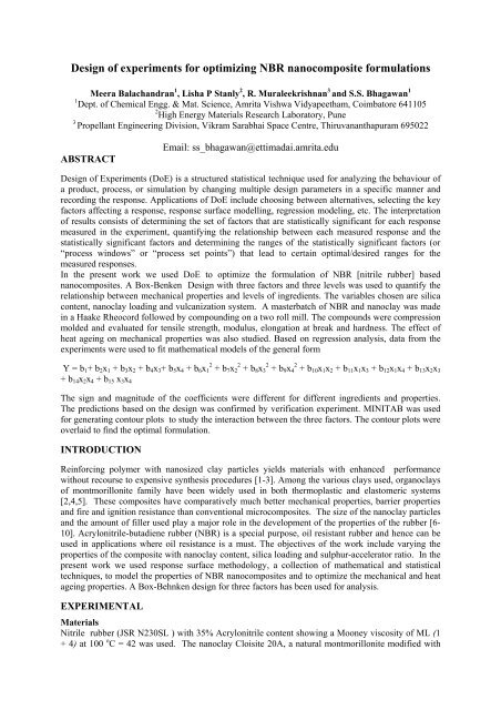
Design <strong>of</strong> experiments for optimiz<strong>in</strong>g NBR nanocomposite formulations<br />
Meera Balachandran 1 , Lisha P Stanly 2 , R. Muraleekrishnan 3 and S.S. Bhagawan 1<br />
1 Dept. <strong>of</strong> Chemical Engg. & Mat. Science, Amrita Vishwa Vidyapeetham, Coimbatore 641105<br />
2 High Energy Materials Research Laboratory, Pune<br />
3 Propellant Eng<strong>in</strong>eer<strong>in</strong>g Division, Vikram Sarabhai Space Centre, Thiruvananthapuram 695022<br />
ABSTRACT<br />
Email: ss_bhagawan@ettimadai.amrita.edu<br />
Design <strong>of</strong> Experiments (DoE) is a structured statistical technique used for analyz<strong>in</strong>g the behaviour <strong>of</strong><br />
a product, process, or simulation by chang<strong>in</strong>g multiple design parameters <strong>in</strong> a specific manner and<br />
record<strong>in</strong>g the response. Applications <strong>of</strong> DoE <strong>in</strong>clude choos<strong>in</strong>g between alternatives, select<strong>in</strong>g the key<br />
factors affect<strong>in</strong>g a response, response surface modell<strong>in</strong>g, regression model<strong>in</strong>g, etc. The <strong>in</strong>terpretation<br />
<strong>of</strong> results consists <strong>of</strong> determ<strong>in</strong><strong>in</strong>g the set <strong>of</strong> factors that are statistically significant for each response<br />
measured <strong>in</strong> the experiment, quantify<strong>in</strong>g the relationship between each measured response and the<br />
statistically significant factors and determ<strong>in</strong><strong>in</strong>g the ranges <strong>of</strong> the statistically significant factors (or<br />
“process w<strong>in</strong>dows” or “process set po<strong>in</strong>ts”) that lead to certa<strong>in</strong> optimal/desired ranges for the<br />
measured responses.<br />
In the present work we used DoE to optimize the formulation <strong>of</strong> NBR [nitrile rubber] based<br />
nanocomposites. A Box-Benken Design with three factors and three levels was used to quantify the<br />
relationship between mechanical properties and levels <strong>of</strong> <strong>in</strong>gredients. The variables chosen are silica<br />
content, nanoclay load<strong>in</strong>g and vulcanization system. A masterbatch <strong>of</strong> NBR and nanoclay was made<br />
<strong>in</strong> a Haake Rheocord followed by compound<strong>in</strong>g on a two roll mill. The compounds were compression<br />
molded and evaluated for tensile strength, modulus, elongation at break and hardness. The effect <strong>of</strong><br />
heat age<strong>in</strong>g on mechanical properties was also studied. Based on regression analysis, data from the<br />
experiments were used to fit mathematical models <strong>of</strong> the general form<br />
Y = b1+ b2x1 + b3x2 + b4x3+ b5x4 + b6x1 2 + b7x2 2 + b8x3 2 + b9x4 2 + b10x1x2 + b11x1x3 + b12x1x4 + b13x2x3<br />
+ b14x2x4 + b15 x3x4<br />
The sign and magnitude <strong>of</strong> the coefficients were different for different <strong>in</strong>gredients and properties.<br />
The predictions based on the design was confirmed by verification experiment. MINITAB was used<br />
for generat<strong>in</strong>g contour plots to study the <strong>in</strong>teraction between the three factors. The contour plots were<br />
overlaid to f<strong>in</strong>d the optimal formulation.<br />
INTRODUCTION<br />
Re<strong>in</strong>forc<strong>in</strong>g polymer with nanosized clay particles yields materials with enhanced performance<br />
without recourse to expensive synthesis procedures [1-3]. Among the various clays used, organoclays<br />
<strong>of</strong> montmorillonite family have been widely used <strong>in</strong> both thermoplastic and elastomeric systems<br />
[2,4,5]. These composites have comparatively much better mechanical properties, barrier properties<br />
and fire and ignition resistance than conventional microcomposites. The size <strong>of</strong> the nanoclay particles<br />
and the amount <strong>of</strong> filler used play a major role <strong>in</strong> the development <strong>of</strong> the properties <strong>of</strong> the rubber [6-<br />
10]. Acrylonitrile-butadiene rubber (NBR) is a special purpose, oil resistant rubber and hence can be<br />
used <strong>in</strong> applications where oil resistance is a must. The objectives <strong>of</strong> the work <strong>in</strong>clude vary<strong>in</strong>g the<br />
properties <strong>of</strong> the composite with nanoclay content, silica load<strong>in</strong>g and sulphur-accelerator ratio. In the<br />
present work we used response surface methodology, a collection <strong>of</strong> mathematical and statistical<br />
techniques, to model the properties <strong>of</strong> NBR nanocomposites and to optimize the mechanical and heat<br />
age<strong>in</strong>g properties. A Box-Behnken design for three factors has been used for analysis.<br />
EXPERIMENTAL<br />
Materials<br />
Nitrile rubber (JSR N230SL ) with 35% Acrylonitrile content show<strong>in</strong>g a Mooney viscosity <strong>of</strong> ML (1<br />
+ 4) at 100 o C = 42 was used. The nanoclay Cloisite 20A, a natural montmorillonite modified with
quaternary ammonium salt (organic modifier - dimethyl dehydrogenated tallow, quaternary<br />
ammonium, modifier concentration 95 meq/100g clay and d001 =24.2Å ) was procured from Southern<br />
Clay Products, USA. Silica [Ultrasil], sulphur, dicumyl peroxide and other compound<strong>in</strong>g <strong>in</strong>gredients,<br />
were obta<strong>in</strong>ed from standard suppliers.<br />
Preparation <strong>of</strong> Nanocomposites<br />
Cloisite 20A was mixed <strong>in</strong>to NBR <strong>in</strong> the ratio 1:3 us<strong>in</strong>g an <strong>in</strong>ternal mixer type Fissions Haake<br />
Rheocord 90 at 60 rpm and at 50°C for 10 m<strong>in</strong>utes. The <strong>in</strong>ternal mixer has an 8-shaped chamber <strong>in</strong><br />
which two sigmoid, counter-rotat<strong>in</strong>g blades turn. The NBR – nanoclay masterbatch was later<br />
compounded with NBR and other compound<strong>in</strong>g <strong>in</strong>gredients <strong>in</strong> laboratory size two roll mill (15cm x<br />
33cm) with friction ratio 1 : 1.25 at room temperature us<strong>in</strong>g standard procedures. The rubber<br />
formulations were evaluated for cure characteristics on TechPro Rheotech ODR. (ASTM D-2084)).<br />
Cur<strong>in</strong>g was done at 150°C and 200 kg/cm² for the optimum cure time <strong>in</strong> a hydraulic press to make ~<br />
2mm thick rubber sheets.<br />
Characterization <strong>of</strong> NBR Nanocomposites.<br />
Dumbbell specimens were punched out from the molded sheets and stress-stra<strong>in</strong> characteristics were<br />
evaluated as per ASTM D412 method on a UTM . The dumbbell specimens were subjected to heat<br />
age<strong>in</strong>g at 100°C for 48 hours.<br />
Design Selection for Property Optimization<br />
A Box-Benken design was chosen for the study consider<strong>in</strong>g its efficiency <strong>in</strong> the number <strong>of</strong> required<br />
runs. Also, this design does not conta<strong>in</strong> any po<strong>in</strong>ts at the vertices <strong>of</strong> the cubic region created by upper<br />
and lower limits for each variable and hence is advantageous when these po<strong>in</strong>ts are impossible to be<br />
tested because <strong>of</strong> physical constra<strong>in</strong>ts. The three level three factor Box-Benken design employed <strong>in</strong><br />
this study required 15 experiments. [11 -15] with silica content (X1), Nanoclay load<strong>in</strong>g (X2) and<br />
sulphur / Accelerator ratio (X3) as the <strong>in</strong>dependent variables. The compositions were optimized for<br />
mechanical properties and heat age<strong>in</strong>g properties. The coded and uncoded levels <strong>of</strong> the <strong>in</strong>dependent<br />
variables are given <strong>in</strong> Table 1.<br />
RESULTS AND DISCUSSION<br />
The mechanical properties <strong>of</strong> NBR nanocomposites before and after heat age<strong>in</strong>g are tabulated <strong>in</strong><br />
Table 2. A wide range <strong>of</strong> values were observed for the different NBR compounds..<br />
Statistical analysis<br />
The experimental data obta<strong>in</strong>ed by follow<strong>in</strong>g the above procedures were analyzed by the response<br />
surface regression procedure us<strong>in</strong>g the follow<strong>in</strong>g second-order polynomial equation:<br />
where y is the response xi and xj are the uncoded <strong>in</strong>dependent variables and β0, βi, βii and βij are<br />
<strong>in</strong>tercept, l<strong>in</strong>ear, quadratic and <strong>in</strong>teraction constant coefficients, respectively. MINITAB s<strong>of</strong>tware<br />
package was used for regression analysis. The regression coefficients for the various parameters are<br />
tabulated <strong>in</strong> Table 3. The factors with positive coefficients have a positive effect on the property and<br />
vice versa. Us<strong>in</strong>g the regression equation, the contour diagrams and response surface plots were<br />
generated (fig 1 & 2).<br />
Overlay<strong>in</strong>g <strong>of</strong> Contour Plots<br />
The contour plots for tensile strength, elongation at break, modulus at 100% elongation and<br />
changes <strong>in</strong> tensile strength and modulus after heat age<strong>in</strong>g were overlaid to f<strong>in</strong>d the feasible<br />
region (shown as white region) hav<strong>in</strong>g desired properties [Fig 3 & 4]. The desired values <strong>of</strong> all<br />
these properties can be obta<strong>in</strong>ed at any given comb<strong>in</strong>ation with<strong>in</strong> the optimized region. For the<br />
purpose <strong>of</strong> overlay<strong>in</strong>g, nanoclay and silica contents were chosen as variables keep<strong>in</strong>g the<br />
value <strong>of</strong> sulphur/accelerator ratio constant at mid po<strong>in</strong>t.
Verification Experiments<br />
Confirmatory experiments were carried out to validate the equations, us<strong>in</strong>g comb<strong>in</strong>ations <strong>of</strong><br />
<strong>in</strong>dependent variables which were not part <strong>of</strong> the orig<strong>in</strong>al experimental design but were with<strong>in</strong> the<br />
experimental region.The values are listed <strong>in</strong> table 4. The predicted and experimental values were <strong>in</strong><br />
good agreement. These validations confirmed the suitability <strong>of</strong> the design chosen, method <strong>of</strong> sample<br />
preparation and property evaluation.<br />
CONCLUSION<br />
Silica load<strong>in</strong>g, nanoclay content and sulphur / accelerator ratio <strong>of</strong> NBR compounds were optimized<br />
us<strong>in</strong>g Design <strong>of</strong> Experiments approach. The nanocomposites were characterized for Tensile Strength,<br />
Modulus and Elongation at break, both before and after heat age<strong>in</strong>g. The data obta<strong>in</strong>ed were used to<br />
generate models by l<strong>in</strong>ear regression analysis us<strong>in</strong>g MINITAB package. Contour plots [a series <strong>of</strong><br />
curves that identified different comb<strong>in</strong>ations <strong>of</strong> variables for which the response was constant] for<br />
tensile strength, elongation, modulus and change <strong>in</strong> tensile strength and modulus after heat age<strong>in</strong>g<br />
were overlaid to provide an optimum region for a desired set <strong>of</strong> specifications. Results from<br />
verification experiments were found to be with<strong>in</strong> reasonable limits.<br />
Table 1 Coded and Uncoded levels <strong>of</strong> Independent Variables – NBR –nanoclay systems<br />
VARIABLE LOW (-1) MID (0) HIGH (1)<br />
Silica Load<strong>in</strong>g (X1), phr 0 10 20<br />
Nanoclay Content (X2),<br />
phr 0 5 10<br />
Sulphur/Accelerator ratio<br />
(X3) 0.3 2 3.7<br />
Table 2 Three variable Box – Behnken design <strong>in</strong> coded units and Mechanical properties NBR<br />
Nanocomposites<br />
RO Name Silica<br />
Coded Variable Properties before Heat Age<strong>in</strong>g Properties before Heat Age<strong>in</strong>g<br />
Nano<br />
-clay<br />
S/Accl<br />
Ratio<br />
TS Eb M100 M300 TS Eb M100 M300<br />
N/mm 2 % N/mm 2<br />
N/mm 2<br />
N/mm 2 % N/mm 2<br />
N/mm 2<br />
1 NBR201 -1 1 0 6.44 757 1.36 2.39 4.96 486 1.58 2.97<br />
2 NBR202 0 0 0 7.89 1063 1.20 1.91 6.87 736 1.43 2.40<br />
3 NBR203 0 1 -1 7.99 1279 1.13 1.62 6.81 919 1.21 1.81<br />
4 NBR204 0 0 0 7.28 1013 1.06 1.81 7.76 797 1.53 2.55<br />
5 NBR205 -1 0 1 5.07 556 1.35 2.57 4.49 400 1.55 3.23<br />
6 NBR206 1 -1 0 11.14 1378 1.01 1.54 8.70 917 1.27 2.09<br />
7 NBR207 0 -1 1 5.16 762 1.00 1.61 5.49 601 1.26 2.27<br />
8 NBR208 0 -1 -1 4.76 1392 0.74 0.95 4.03 958 0.83 1.11<br />
9 NBR209 1 0 -1 8.15 1488 0.90 1.36 7.81 1116 1.04 1.36<br />
10 NBR210 -1 -1 0 2.77 720 0.78 1.18 2.43 536 0.92 1.37<br />
11 NBR211 1 1 0 11.41 1129 1.37 2.46 11.46 870 1.72 3.21<br />
12 NBR212 -1 0 -1 4.23 958 0.79 1.31 4.01 748 1.01 1.59<br />
13 NBR213 1 0 1 12.90 944 1.54 2.98 11.37 644 2.05 4.30<br />
14 NBR214 0 0 0 8.49 1079 1.09 1.93 7.94 771 1.47 2.56<br />
15 NBR215 0 1 1 11.60 766 1.80 3.74 9.16 515 2.34 4.90
Table 3 Regression Coefficients for Properties <strong>of</strong> NBR Nanocomposites<br />
Term<br />
Tensile<br />
Strength<br />
Before heat age<strong>in</strong>g After Heat age<strong>in</strong>g<br />
Eb M100<br />
Tensile<br />
Strength<br />
Eb M100<br />
N/mm2 % N/mm2 N/mm2 % N/mm2<br />
Constant β0 7.89 1051.51 1.12 7.52 768.18 1.48<br />
Silica β1 3.13 243.30 0.07 2.93 172.23 0.13<br />
Nanoclay β2 1.70 -40.21 0.27 1.47 -27.68 0.32<br />
S/Accl Ratio β3 1.20 -261.21 0.27 0.98 -197.72 0.39<br />
Silica*Silica β12 0.13 -59.37 0.00 -0.05 -43.48 -0.05<br />
Nanoclay*Nanoclay β22 -0.08 3.84 0.02 -0.59 -22.19 -0.05<br />
S/Accl Ratio*S/Accl Ratio β32 -0.43 -5.62 0.03 -0.56 2.35 -0.02<br />
Silica*Nanoclay β1β2 -0.85 -71.57 -0.05 0.06 0.66 -0.05<br />
Silica*S/Accl Ratio β1β3 0.98 -35.55 0.02 0.77 -30.99 0.12<br />
Nanoclay*S/Accl Ratio β2β3 0.80 29.22 0.10 0.22 -11.78 0.18<br />
Table 4 Comparison <strong>of</strong> the predicted and the observed values<br />
% change from<br />
actual<br />
Tensile strength,<br />
N/mm2<br />
Elongation at Break ,<br />
7.40 7.68 3.7<br />
% 914 811 -12.6<br />
M100 , N/mm2<br />
Tensile strength,<br />
1.24 1.27 2.6<br />
N/mm2<br />
Elongation at Break ,<br />
6.62 7.53 12.1<br />
% 652 602 -8.2<br />
M100 , N/mm2 1.56 1.64 5.0<br />
Properties Predicted Experimental<br />
Before heat<br />
Age<strong>in</strong>g<br />
After heat Age<strong>in</strong>g<br />
Fig 1. Contour Plots for Tensile Strength Fig 2. Response Surface Plots for Tensile strength
Fig 3 Overlaid contour plots for<br />
tensile strength, Elongation at<br />
break and M100<br />
REFERENCES<br />
Fig 4 Overlaid contour plots for tensile<br />
strength, Elongation at break, M100<br />
and change <strong>in</strong> these properties after<br />
1. T.V. Yen , James E.M., et al. (2001),. J Appl Polym Sci., 82, 1391-1403.<br />
2. T.J. P<strong>in</strong>navaia and Beall G. W (Eds), “Polymer-Clay Nanocomposites”, Wiley, New<br />
York, Ch 11 and 13 (2000)<br />
3. A. Mousa & J. Karger-Kocsis (2001). Macromol .Mater. Eng, 286, 260-266.<br />
4. J<strong>in</strong>-tae Kim, Taeg-su Oh and Dong-ho Lee, Poly Intl, 52:1058–1063 (2003)<br />
5. Yurong Liang, Yiq<strong>in</strong>g Wang, et al., Poly Test<strong>in</strong>g 24 (2005) 12-17<br />
6. A. B. Morgan, W.G. Jeffrey, J App Poly Sci, 87 (2003) 1329-1338<br />
7. S. Varghese, J. Karger-Kocsis, Polymer, 44 (2003) 4921-1927<br />
8. S. Sadhu and A. K. Bhowmick, J Appl Poly Sci : Part B, Poly. Phy. 42, 1573 (2004)<br />
9. A. M. Shanmugaraj, A. K. Bhowmick, J Appl Polym Sci, 88, 2992 (2003)<br />
10. Wei-Gwo Hwang, Kung-Hwa Wei & Chang-Mon Wu, Polymer 45(2004) 5729-5734<br />
11. D.C. Montgomery, Design and Analysis <strong>of</strong> Experiments, 4 th Edn, John Wiley, 1996<br />
12. Paritosh Ja<strong>in</strong>, R.Muraleekrishnan, S.S. Bhagawan, M.S.Rao, “Response Surface<br />
Methodology: A tool for develop<strong>in</strong>g low SBR compounds”, <strong>in</strong> Macromolecules : New<br />
Frontiers, Vol II, Ed. K.S.V.Sr<strong>in</strong>ivasan, John Wiley, New Delhi, 1998, 1058-61<br />
13. E. Hajizadeh, and H. Garmabi, “Response Surface Based Optimization <strong>of</strong> Toughness <strong>of</strong><br />
Hybrid Polyamide 6 Nanocomposites”, Intl J Chem Biomol Engg, 2008, 1(1), 40-44.<br />
14. V. Mittal, “Model<strong>in</strong>g the Behavior <strong>of</strong> Polymer-layered Silicate Nanocomposites us<strong>in</strong>g<br />
Factorial and Mixture Designs”, Jl Thermoplastic Compos Matl, 2008, 21,9<br />
15. S.S. Bhagawan, “Statistical Design <strong>in</strong> Polymer Process<strong>in</strong>g” <strong>in</strong> ‘Polymer Process<strong>in</strong>g<br />
Technology’, B.R. Gupta (Ed), Asian Books, New Delhi, 2008
Studies on pressure sensitive <strong>adhesive</strong>s based on blends <strong>of</strong> natural rubber<br />
and polychloroprene rubber modified with phosphorylated cashew nut<br />
ABSTRACT<br />
shell liquid prepolymer<br />
A.R.R. Menon # , J. Chameswary and J.D. Sudha<br />
National Institute for Interdiscipl<strong>in</strong>ary Science and Technology (NIIST, CSIR)<br />
Thiruvananthapuram – 695 019, Kerala, INDIA<br />
Email : rav<strong>in</strong>dranathamenon@yahoo.co.<strong>in</strong><br />
Effect <strong>of</strong> compositional and process<strong>in</strong>g variations on the T-peel adhesion strength <strong>of</strong> rex<strong>in</strong><br />
specimens bonded with phosphorylated cashew nut shell liquid prepolymer (PCNSL) based pressure<br />
sensitive <strong>adhesive</strong>s (PSAs) conta<strong>in</strong><strong>in</strong>g natural rubber (NR) and polychloroprene rubber (CR) has been<br />
studied. Increase <strong>in</strong> adhesion strength above that <strong>of</strong> a commercial sample <strong>of</strong> PSA has been observed<br />
with the <strong>in</strong>crease <strong>in</strong> solids content <strong>of</strong> the PCNSL based PSA from 15% to 25%. Also, considerable<br />
<strong>in</strong>crease <strong>in</strong> adhesion strength has been obta<strong>in</strong>ed with the <strong>in</strong>crease <strong>in</strong> storage time prior to <strong>test<strong>in</strong>g</strong> <strong>of</strong> the<br />
specimens from 1 to 7 days which <strong>in</strong>dicates the time dependent diffusion behavior <strong>of</strong> PCNSL based<br />
PSA facilitat<strong>in</strong>g wett<strong>in</strong>g and bond formation with the substrates. Irrespective <strong>of</strong> the solids content and<br />
the type <strong>of</strong> PCNSL, a maximum <strong>in</strong> T-peel adhesion strength has been obta<strong>in</strong>ed at a CR dosage <strong>of</strong> 90<br />
phr <strong>in</strong> the blend. Typical cohesive failure along-with high strength have been obta<strong>in</strong>ed with PSAs<br />
based on PCNSL hav<strong>in</strong>g a higher degree <strong>of</strong> phosphorylation / oligomerization. Uniform and almost<br />
complete wett<strong>in</strong>g <strong>of</strong> the substrate has been confirmed by the optical stereo micrographs <strong>of</strong> the failure<br />
surfaces <strong>of</strong> the test specimens and the results on viscosity obta<strong>in</strong>ed from rheometry.<br />
INTRODUCTION<br />
Pressure sensitive <strong>adhesive</strong>s (PSAs) 1 , popularly known as ‘contact <strong>adhesive</strong>s’ hold a ma<strong>in</strong> stay <strong>in</strong><br />
the present consumer and <strong>in</strong>dustrial market. A variety <strong>of</strong> PSAs based on natural rubber (NR) and<br />
polychloroprene rubber (CR) modified with tackifiers and other additives have been <strong>in</strong> use for various<br />
applications such as removable tapes / labels, upholstery, carpentry and footwears. 2-4 It has been<br />
established by the results <strong>of</strong> previous studies that Phosphorylated Cashew Nut Shell Liquid<br />
prepolymer (PCNSL) – an amphiphyllic derivative <strong>of</strong> cashew nut shell liquid (CNSL) could function<br />
as an excellent multifunctional additive for rubber compound<strong>in</strong>g. 5-7 The chemical structure <strong>of</strong> PCNSL<br />
prepolymer is given <strong>in</strong> Fig. 1. The multifunctional role <strong>of</strong> PCNSL as a plasticizer, antioxidant and<br />
tackifier has been made use <strong>of</strong> <strong>in</strong> the design and development <strong>of</strong> a series <strong>of</strong> solvent based PSAs<br />
conta<strong>in</strong><strong>in</strong>g NR and CR. A prelim<strong>in</strong>ary study was made on the effect <strong>of</strong> different compositional and
process<strong>in</strong>g variables on the adhesion strength <strong>of</strong> substrates bonded with these PSAs - the results <strong>of</strong><br />
which are reported <strong>in</strong> this paper.<br />
O<br />
HO OH<br />
P<br />
O<br />
( CH2)7 CH CH CH2 CH CH CH2<br />
(I)<br />
Prepolymer <strong>of</strong> PCNSL<br />
Materials & Methods<br />
(<br />
CH CH2 )<br />
n<br />
n = 2 to 4<br />
Polychloroprene rubber (CR) (Skyprene Y-30H, Toyo Soda Co.) was supplied by M/s. Jeni<br />
Polyplast, Ahmedabad, Gujarat, India. CNSL conform<strong>in</strong>g to Indian Standards IS: 840 - 1964 was<br />
supplied by M/s. Adarsh Industrial Chemicals, Sanoor, Mangalore, India. Commercial sample <strong>of</strong> PSA<br />
(Fevicol SR 998) was manufactured by M/s. Pidilite Industries Pvt. Ltd., Mumbai, India.<br />
PCNSL was synthesized (at 20 kg level) by the simultaneous esterification and oligomerization <strong>of</strong><br />
CNSL us<strong>in</strong>g o-phosphoric acid at controlled temperature, time and vacuum conditions <strong>in</strong> a Multi<br />
Purpose Reactor (Pyrodevices) supplied by M/s. Thermosystems, Veli, Thiruvananthapuram.<br />
Blends <strong>of</strong> NR, CR and PCNSL (<strong>in</strong> various proportions) were prepared by mix<strong>in</strong>g on an open two<br />
roll mill (6” X 12”) for 5 m<strong>in</strong>utes followed by homogenization and sheet<strong>in</strong>g out. The sheets were cut<br />
to small pieces and weighed amounts <strong>of</strong> the same were kept immersed <strong>in</strong> requisite amount <strong>of</strong><br />
dichloromethane for 24 h, stirred there-after for homogeneity and kept <strong>in</strong> air-tight conta<strong>in</strong>ers.<br />
The viscosity <strong>of</strong> the PSAs was measured on a rheometer (Anton Paar Physica, Austria, model<br />
MCR-150) by parallel plate method, at 28°C over the shear rate range from 0.1 s 1 to 100 s 1 . T-peel<br />
test specimens were prepared from rex<strong>in</strong> sheet cut to size (75 mm X 25 mm). Two coats <strong>of</strong> the PSA<br />
were applied manually on an area <strong>of</strong> 50 mm X 25 mm from one end <strong>of</strong> the fabric surface, an open<br />
tack time <strong>of</strong> 2 m<strong>in</strong>utes was given and bonded together under hand pressure. The test specimens were<br />
kept pressed between two flat sheets under a load <strong>of</strong> 10 kg, applied uniformly for a period <strong>of</strong> 24 h or<br />
168 h. The T-peel adhesion strength <strong>of</strong> the specimens was measured on a Universal Tensile <strong>test<strong>in</strong>g</strong><br />
Mach<strong>in</strong>e (Hounsfield, H5KS) at a cross head speed <strong>of</strong> 100 mm/m<strong>in</strong>. The optical micro photographs<br />
<strong>of</strong> the failure surfaces were obta<strong>in</strong>ed us<strong>in</strong>g a stereo microscope (Leica MZ 16A / DC Twa<strong>in</strong>) at a<br />
magnification <strong>of</strong> X 11.<br />
RESULTS AND DISCUSSION<br />
Effect <strong>of</strong> type <strong>of</strong> PCNSL and storage time <strong>of</strong> bonded specimens on adhesion strength<br />
The results on T-peel strength <strong>of</strong> rex<strong>in</strong> specimens bonded with the PCNSL based PSAs are given<br />
<strong>in</strong> Table 1. It shows a general <strong>in</strong>crease <strong>in</strong> the T-peel strength with the change <strong>in</strong> type <strong>of</strong> PCNSL from<br />
2
PCNSL-1 to PCNSL-3. This is expected to be due to the <strong>in</strong>crease <strong>in</strong> cohesive strength <strong>of</strong> the PSA<br />
based on it due to the <strong>in</strong>crease <strong>in</strong> molecular weight / viscosity up on chang<strong>in</strong>g from PCNSL-1 to<br />
PCNSL-3. Also, at higher solids contents the nature <strong>of</strong> failure changed from ‘<strong>adhesive</strong>’ to ‘cohesive’<br />
NR / CR / PCNSL (phr) 100 / 0 / 5 0 / 100 / 5<br />
Storage time (days) 1 7 1 7<br />
TSC (%) Mean T-peel strength (N/25mm)<br />
PCNSL - 1 15 5.4 9.2 13.7 16.5<br />
PCNSL - 2<br />
PCNSL -3<br />
20 8.8 10.4 21.5 33.7<br />
25 9.1 11.5 34.8 41<br />
15 5.3 7.3 14.6 18<br />
20 8.7 11 18.8 30<br />
25 9.3 12.1 33.3 45.3<br />
15 6.3 7.4 15 16.9<br />
20 9.7 14.1 26 33.1<br />
25 13.4 17.1 32.6 43.9<br />
Table 1. Variation <strong>in</strong> T-peel strength <strong>of</strong> rex<strong>in</strong> / rex<strong>in</strong> bonded with PCNSL based PSAs<br />
type similar to that <strong>of</strong> the commercial sample. The adhesion strength <strong>of</strong> rex<strong>in</strong> specimens bonded with<br />
PCNSL based PSAs <strong>in</strong>crease with storage time from 1 to 7 days. This is more prom<strong>in</strong>ent <strong>in</strong> the<br />
<strong>adhesive</strong> conta<strong>in</strong><strong>in</strong>g higher solids content, higher proportion <strong>of</strong> CR and PCNSL hav<strong>in</strong>g a higher<br />
extent <strong>of</strong> oligomerization / phosphorylation. Time dependent diffusion <strong>of</strong> the PSA to the substrate<br />
matrix aid<strong>in</strong>g ‘wett<strong>in</strong>g’ may be one <strong>of</strong> the reasons for the <strong>in</strong>crease <strong>in</strong> adhesion strength. A similar<br />
time dependent <strong>in</strong>crease <strong>in</strong> self adhesion strength (tack) <strong>of</strong> PCNSL modified NR has been reported<br />
earlier 5 which was ascribed to higher molecular diffusion <strong>of</strong> NR assisted by the plasticiz<strong>in</strong>g effect <strong>of</strong><br />
PCNSL. The T-peel strength <strong>of</strong> rex<strong>in</strong> bonded with Fevicol SR 998 showed a peak value (19N/25 mm)<br />
after stor<strong>in</strong>g for five days. This may probably be facilitated by its very low value <strong>of</strong> viscosity.<br />
However, it can be noted that the <strong>in</strong>crease <strong>in</strong> adhesion strength is comparatively greater for the<br />
PCNSL modified CR based PSAs, particularly at the higher solids contents, as shown <strong>in</strong> Table 1. The<br />
progressively decreas<strong>in</strong>g viscosity at higher shear rates <strong>of</strong> PCNSL – 1, PCNSL-2 and PCNSL-3<br />
based PSAs may aid the flow <strong>of</strong> the <strong>adhesive</strong> and wett<strong>in</strong>g <strong>of</strong> the substrates, facilitat<strong>in</strong>g development<br />
<strong>of</strong> a higher bond strength over a longer period <strong>of</strong> time. This <strong>in</strong>creas<strong>in</strong>g adhesion strength may also be<br />
due to possible physico-chemical <strong>in</strong>teraction between CR and PCNSL as mentioned <strong>in</strong> an earlier<br />
work 7 where-<strong>in</strong> the polar phosphate group <strong>of</strong> PCNSL can <strong>in</strong>teract with the chloro-group <strong>of</strong> CR. Polar<br />
– polar <strong>in</strong>teraction between an additive and PSA has been reported as a factor responsible for a high<br />
value <strong>of</strong> T- peel strength. 8 Table 2 shows the mean T-peel strength <strong>of</strong> rex<strong>in</strong> bonded with PSAs based<br />
on unmodified blends <strong>of</strong> NR and CR, tested after 24 h. The lower values <strong>of</strong> adhesion strength here is<br />
<strong>in</strong> sharp contrast to the considerably higher values for the PCNSL based PSAs shown <strong>in</strong> Table 1.<br />
3
NR / CR<br />
TSC (%)<br />
100 / 0 75 / 25 50 / 50 25 / 75<br />
Mean T-peel 15 2.4 3.3 4.9 3.7<br />
strength (N/25mm) 20 2.8 3.6 4.5 4.8<br />
Table 2. T-peel strength <strong>of</strong> rex<strong>in</strong> / rex<strong>in</strong> bonded with unmodified NR/CR based PSAs<br />
In the former, the lower segmental mobility <strong>of</strong> the elastomeric cha<strong>in</strong>s <strong>in</strong> the absence <strong>of</strong> PCNSL may<br />
reduce the flow and wett<strong>in</strong>g <strong>of</strong> the substrates, essential for development <strong>of</strong> a high value <strong>of</strong> adhesion<br />
strength. It is expected that the plasticiz<strong>in</strong>g and s<strong>of</strong>ten<strong>in</strong>g effect <strong>of</strong> PCNSL <strong>in</strong> NR 5 and CR 6 as<br />
reported earlier facilitates the built up <strong>of</strong> <strong>adhesive</strong> tack <strong>in</strong> the PCNSL modified PSAs.<br />
Effect <strong>of</strong> solids content <strong>of</strong> PSA on adhesion characteristics<br />
The optical micro-photographs <strong>of</strong> the failure surfaces <strong>of</strong> rubber specimens bonded with Fevicol<br />
SR 998 and PCNSL based PSAs are given as Figure 2.<br />
(a) (b)<br />
Fig.2.T-peel failure surface <strong>of</strong> rubber / rubber bonded with (a) Fevicol and (b) PCNSL based PSA,<br />
(TSC – 30%)<br />
Figure 2(a) shows almost uniform and complete wett<strong>in</strong>g <strong>of</strong> the substrate with a layer <strong>of</strong> the <strong>adhesive</strong>.<br />
A similar morphology was observed for the PCNSL based <strong>adhesive</strong> at 30% solids content (Fig.2(b)).<br />
This was reflected <strong>in</strong> the <strong>in</strong>crease <strong>in</strong> T-peel adhesion strength from 10% to 30% solids content, as<br />
given <strong>in</strong> Table 3. Also, the nature <strong>of</strong> adhesion failure changed from ‘<strong>adhesive</strong>’ to ‘cohesive’ type with<br />
PSA TSC (%) Mean T-peel strength (N/25mm)<br />
Fevicol SR 998 - 39.5<br />
NR/CR/PCNSL 10 15.8<br />
20 25.9<br />
30 45.5<br />
Table 3.T-peel strength <strong>of</strong> rubber / rubber bonded with Fevicol and PCNSL based PSA<br />
the <strong>in</strong>crease <strong>in</strong> solids content.<br />
Effect <strong>of</strong> proportion <strong>of</strong> CR and type <strong>of</strong> PCNSL on adhesion strength<br />
Table 2 gives the T- peel adhesion strength <strong>of</strong> rex<strong>in</strong> specimens bonded with PSAs based on<br />
blends <strong>of</strong> NR and CR at two different solids contents. It can be noted that irrespective <strong>of</strong> the content<br />
4
<strong>of</strong> CR and solids content, all <strong>of</strong> the unmodified <strong>adhesive</strong>s show low values <strong>of</strong> adhesion strength. The<br />
lower adhesion strength <strong>of</strong> the unmodified <strong>adhesive</strong>s may be due to the absence <strong>of</strong> a plasticizer and /<br />
or tackifier which are known to be essential constituents <strong>of</strong> an elastomeric PSA.<br />
Figure 3 shows that the PCNSL based PSAs show a maximum <strong>in</strong> the T-peel strength at a CR<br />
content <strong>of</strong> 90 phr. Also, at all the different proportions <strong>of</strong> NR and CR there is a gradual <strong>in</strong>crease <strong>in</strong> T-<br />
peel strength (<strong>in</strong> the order PCNSL-1 < PCNSL-2 < PCNSL-3) with a change <strong>in</strong> the type <strong>of</strong> PCNSL.<br />
Mean T-peel strength (N/25mm)<br />
55<br />
50<br />
45<br />
40<br />
35<br />
30<br />
25<br />
20<br />
15<br />
10<br />
5<br />
B<br />
C<br />
D<br />
TSC = 20%<br />
PCNSL - 5 phr<br />
PCNSL - 1<br />
PCNSL - 2<br />
PCNSL - 3<br />
0<br />
0 20 40 60 80 100<br />
Dosage <strong>of</strong> CR (phr)<br />
Fig.3. Variation <strong>in</strong> T-peel adhesion strength <strong>of</strong> rex<strong>in</strong> / rex<strong>in</strong> bonded specimens with dosage <strong>of</strong> CR<br />
<strong>in</strong> the NR/CR/PCNSL blend and at 20% TSC <strong>of</strong> <strong>adhesive</strong>s.<br />
This can be attributed to the <strong>in</strong>crease <strong>in</strong> molecular weight <strong>of</strong> the res<strong>in</strong> <strong>in</strong> that order, contribut<strong>in</strong>g to the<br />
cohesive strength <strong>of</strong> the <strong>adhesive</strong>. Zosel has reported that above a m<strong>in</strong>imum molecular weight <strong>of</strong> the<br />
modifier, tendency for fibrillation <strong>in</strong>creases lead<strong>in</strong>g to an <strong>in</strong>crease <strong>in</strong> cohesive strength <strong>of</strong> PSAs. 9 A<br />
similar mode <strong>of</strong> cohesive failure was observed for rex<strong>in</strong> specimens bonded with the PCNSL based<br />
PSA conta<strong>in</strong><strong>in</strong>g PCNSL-3. This <strong>in</strong>dicates the possibility for entanglement <strong>of</strong> the pre-polymer cha<strong>in</strong>s<br />
<strong>of</strong> PCNSL with macromolecular cha<strong>in</strong>s <strong>of</strong> CR and NR with consequent <strong>in</strong>crease <strong>in</strong> cohesive strength<br />
and T-peel adhesion strength. Also, the small proportion <strong>of</strong> NR (10 phr) may facilitate the visco-<br />
elastic deformation / flow characteristics <strong>of</strong> the <strong>adhesive</strong> facilitat<strong>in</strong>g quick and uniform wett<strong>in</strong>g <strong>of</strong> the<br />
substrates and development <strong>of</strong> a high value <strong>of</strong> adhesion strength. The comparatively lower values <strong>of</strong><br />
viscosity <strong>of</strong> Fevicol SR 998 at various shear rates may be one <strong>of</strong> the factors for its high value <strong>of</strong><br />
adhesion strength. Thus, the low viscosity <strong>of</strong> this <strong>adhesive</strong> leads to almost complete wett<strong>in</strong>g <strong>of</strong> the<br />
substrates as shown <strong>in</strong> the stereo optical micrograph <strong>of</strong> the failure surface, given as Fig.4 (a). The<br />
optical micrograph <strong>of</strong> the failure surface <strong>of</strong> rex<strong>in</strong> bonded with PCNSL based PSA hav<strong>in</strong>g 25% solids<br />
content is given as Figures 4(b).This shows almost complete wett<strong>in</strong>g <strong>of</strong> the substrate, account<strong>in</strong>g for<br />
5
the observed high values <strong>of</strong> its T-peel strength (15.5 N/25mm as aga<strong>in</strong>st 9.8 N/25mm for Fevicol SR<br />
998).<br />
Fig.4.T-peel failure surface <strong>of</strong> rex<strong>in</strong> / rex<strong>in</strong> bonded with (a) Fevicol and (b) PCNSL based PSA<br />
CONCLUSION<br />
Adhesion strength higher than that <strong>of</strong> Fevicol SR 998 was obta<strong>in</strong>ed for PCNSL based PSAs<br />
with <strong>in</strong>creases <strong>in</strong> solids content from 15% to 25% and storage time <strong>of</strong> test specimens prior to <strong>test<strong>in</strong>g</strong><br />
from 1 to 7 days which <strong>in</strong>dicates time dependent diffusion characteristics <strong>of</strong> the latter caus<strong>in</strong>g a<br />
change <strong>in</strong> failure pattern from ‘<strong>adhesive</strong>’ to ‘cohesive’ type. Increase <strong>in</strong> the extent <strong>of</strong> phosphorylation<br />
/ oligomerisation <strong>of</strong> CNSL dur<strong>in</strong>g synthesis <strong>of</strong> PCNSL resulted <strong>in</strong> a res<strong>in</strong> hav<strong>in</strong>g higher viscosity<br />
which enhanced the cohesive strength <strong>of</strong> the PSA and consequently the T-peel adhesion strength with<br />
flexible substrates. Rex<strong>in</strong> specimens bonded with the PCNSL based PSAs showed an optimum high<br />
value <strong>of</strong> T-peel adhesion strength at a CR dosage <strong>of</strong> 90 phr, irrespective <strong>of</strong> the type <strong>of</strong> PCNSL and<br />
solids content.<br />
Acknowledgement: Thanks are due to the Kerala State Council for Science Technology &<br />
Environment<br />
(KSCSTE), Thiruvanthapuram for sponsor<strong>in</strong>g this work and to Pr<strong>of</strong>. T.K. Chandrasekhar, Director,<br />
NIIST, Thiruvananthapuram for provid<strong>in</strong>g the necessary facilities.<br />
REFERENCES<br />
1. Wake, W.C. Adhesion and the formulation <strong>of</strong> <strong>adhesive</strong>s; 2 nd Edn., Appl Sci Pub., New York, 1982,<br />
Ch.10, pp. 220-223.<br />
2. John, N.; Joseph, R. J Appl Polym Sci, 1998, 68, 1185.<br />
3. Poh, B.T.; Kwo, H.K. J Appl Polym Sci, 2007,105 (2), 680.<br />
4. Kozakiewicz, J.; Kujawa-Penczek, B.; Penczek, P.; Puton, K. J Appl Polym Sci, 1981, 26,<br />
3699.<br />
5. Menon, A.R.R.; Pillai, C.K.S. ; Nando, G.B. J Adhesion Sci Technol, 1995, 9(4), 443.<br />
6. Menon, A.R.R.; Pillai, C.K.S.; Nando, G.B.; Bhattacharya, A.K.; Gupta, B.R. Kauts Gummi<br />
6
Kunsts, 2000, 53(1-2), 35.<br />
7. Menon, A.R.R.; Visconte, L.L.Y. J Appl Polym Sci, 2004, 91(3), 1619.<br />
8. Taghizadeh, S.M.; Mirzadeh, H.; Barikani, M. ; Yousefi, M Iran Polym J, 2007, 16(4), 279.<br />
9. Zosel, A. Int J Adhesion & Adhesives, 1998, 18, 265.<br />
7
<strong>Nondestructive</strong> <strong>test<strong>in</strong>g</strong> <strong>of</strong> <strong>defects</strong> <strong>in</strong> <strong>adhesive</strong> jo<strong>in</strong>ts<br />
P.N. V<strong>in</strong>od, Reji John, Shiv Kumar, K. Shajahan, C.G. Padma Kumar and RMR Vishnubhatla<br />
Naval Physical and Oceanographic Laboratory,<br />
Defence Research and Development Organisation,<br />
Thrikkakara P.O, Coch<strong>in</strong>-682 021<br />
Abstract<br />
Email: tsonpol@vsnl.com<br />
Rubbers are generally used for encapsulat<strong>in</strong>g underwater components to prevent moisture<br />
<strong>in</strong>gress. Reliability aspects <strong>of</strong> these components are very important while consider<strong>in</strong>g the performance<br />
<strong>of</strong> the sensor. The sensor is deployed <strong>in</strong> underwater for quite long period <strong>of</strong> time and has no option for<br />
monitor<strong>in</strong>g the structural health and functionality. The sub-surface <strong>defects</strong> such as micro-cracks,<br />
voids, porosity and delam<strong>in</strong>ation are generally <strong>in</strong>troduced dur<strong>in</strong>g the encapsulation or damage may<br />
create due to handl<strong>in</strong>g or when service stress exceeds design stresses. <strong>Nondestructive</strong> test (NDT)<br />
techniques such as <strong>in</strong>frared thermography (IRT) and micro-focal x-ray radiography techniques have<br />
been applied as an <strong>in</strong>spection methodology for detect<strong>in</strong>g these <strong>defects</strong> <strong>in</strong> the encapsulants. The ma<strong>in</strong><br />
advantage <strong>of</strong> the NDT techniques is that reliable and quantitative <strong>in</strong>formation about the hidden <strong>defects</strong><br />
or flaws can be generated with high precision without sacrific<strong>in</strong>g or damag<strong>in</strong>g the entire structure <strong>of</strong><br />
the device or its components. The bright spots and its dimensions observed on the IR images <strong>of</strong> the<br />
partially debonded samples correspond to the location as well as the relative size <strong>of</strong> the delam<strong>in</strong>ation<br />
presents <strong>in</strong> the sample. The x-ray image <strong>of</strong> the spiced cable jo<strong>in</strong>ts shows that the <strong>in</strong>ternal structure<br />
with cracks or voids at the cable jo<strong>in</strong>ts.<br />
Keywords: encapsulants, NDT, <strong>in</strong>frared thermal imag<strong>in</strong>g and micr<strong>of</strong>ocal x-ray radiography.<br />
1. Introduction<br />
Rubbers are generally used for encapsulat<strong>in</strong>g underwater components to prevent moisture<br />
<strong>in</strong>gress. The sensor is deployed <strong>in</strong> underwater for quite long period <strong>of</strong> time and has no option for<br />
monitor<strong>in</strong>g the structural health and functionality on a regular basis. The generally observed <strong>defects</strong> <strong>of</strong><br />
underwater components are delam<strong>in</strong>ation <strong>of</strong> <strong>adhesive</strong> jo<strong>in</strong>ts or at the cable-spliced jo<strong>in</strong>ts, cracks <strong>in</strong><br />
ceramics, porosity and p<strong>in</strong> holes <strong>in</strong> transducer encapsulations and rubber moulded junction boxes,<br />
which are seriously affect<strong>in</strong>g the reliability <strong>of</strong> the sonar systems. Hence, detection and localization <strong>of</strong><br />
the above types <strong>of</strong> <strong>defects</strong> and monitor<strong>in</strong>g the health <strong>of</strong> the components are the prime important<br />
factors to improve the reliability <strong>of</strong> the device and <strong>in</strong> predict<strong>in</strong>g the life <strong>of</strong> the components, thereby<br />
elim<strong>in</strong>at<strong>in</strong>g the possibility <strong>of</strong> catastrophic failure <strong>of</strong> sonar. These <strong>defects</strong> are so t<strong>in</strong>y that visual<br />
<strong>in</strong>spection is not practically feasible. Consequently, there exists an <strong>in</strong>creas<strong>in</strong>g demand for reliable and<br />
effective non-destructive evaluation (NDE) for the wet-end components <strong>of</strong> the encapsulants. A<br />
number <strong>of</strong> different nondestructive test (NDT) techniques have also been developed as an <strong>in</strong>spection<br />
methodology and applied successfully to identify and characterize the <strong>defects</strong> [ 1- 2]. No s<strong>in</strong>gle<br />
method can detect all forms <strong>of</strong> flaws <strong>in</strong> all materials. Hence, suitable NDT <strong>in</strong>spection methods have to<br />
appropriately select for each case. In the present study, the delam<strong>in</strong>ation and cracks <strong>in</strong> the<br />
encapsulants <strong>of</strong> the wet-end components <strong>of</strong> the underwater sensors have been detected and<br />
characterized us<strong>in</strong>g the NDT technique such as micro-focal x-ray radiography and IR thermal imag<strong>in</strong>g<br />
techniques. These techniques are applied due to their reliability and high sensitivity <strong>in</strong> detect<strong>in</strong>g the<br />
<strong>defects</strong> [ 3].<br />
1. (a) The pr<strong>in</strong>ciple <strong>of</strong> Infrared thermography<br />
Infrared thermography is a non-contact sens<strong>in</strong>g method concerned with the measurement <strong>of</strong><br />
radiated thermal or <strong>in</strong>frared radiation from a surface <strong>in</strong> the <strong>in</strong>frared region. This <strong>in</strong>volves the use <strong>of</strong> an<br />
IR camera to capture the evolution <strong>of</strong> surface temperature pr<strong>of</strong>iles <strong>of</strong> the test object after be<strong>in</strong>g
subjected to thermal perturbation from a high-energy uniform light source. It detects heat signatures<br />
via <strong>in</strong>frared imag<strong>in</strong>g and uses this heat signature to detect leaks, cracks, debond<strong>in</strong>g, corrosion etc. The<br />
spectrum and <strong>in</strong>tensity <strong>of</strong> the radiation emitted by the object depends on its absolute temperature and<br />
emissivity <strong>of</strong> the surface [ 3]. The basic pr<strong>in</strong>ciple <strong>of</strong> this approach is that when a materials present<br />
<strong>defects</strong>; it <strong>in</strong>troduces areas <strong>of</strong> locally high temperature because <strong>of</strong> the reduced heat flux <strong>in</strong> the areas<br />
immediately surround<strong>in</strong>g the <strong>defects</strong>. This results thermal gradients. This thermal transient flux can be<br />
picked up or recorded by an <strong>in</strong>frared camera operat<strong>in</strong>g <strong>in</strong> the <strong>in</strong>frared wavelength range 4 to 9μm. The<br />
analysis <strong>of</strong> the IR images provides qualitative <strong>in</strong>formation about the hidden <strong>defects</strong> or <strong>in</strong>ternal flaws<br />
<strong>in</strong> the material.<br />
1. (b) The pr<strong>in</strong>ciple <strong>of</strong> X-ray radiography measurement<br />
The radiography measurement is based on the differential absorption <strong>of</strong> x-ray radiation on its<br />
transmission through the structure <strong>of</strong> the tested specimen. This <strong>in</strong>dicates that the <strong>in</strong>tensity <strong>of</strong> the<br />
<strong>in</strong>cident radiation on the tested structure is attenuated more or less due to the presence <strong>of</strong> any flaws or<br />
discont<strong>in</strong>uities <strong>in</strong> the specimen. Thickness alterations and the presence <strong>of</strong> discont<strong>in</strong>uities are<br />
visualized by differences <strong>in</strong> contrast (radiographic density) <strong>of</strong> the obta<strong>in</strong>ed images [ 3].<br />
2. Experimental<br />
For detect<strong>in</strong>g the various <strong>defects</strong>-like th<strong>in</strong> l<strong>in</strong>e cracks, voids or sub-surface <strong>defects</strong> on the<br />
spliced neoprene cable, both IR thermal imag<strong>in</strong>g and x-ray micro-focal radiography measurements<br />
were carried out. The tested samples were <strong>adhesive</strong>ly bonded alum<strong>in</strong>um disc with neoprene rubber<br />
used for encapsulat<strong>in</strong>g underwater acoustic sensors hav<strong>in</strong>g delam<strong>in</strong>ation <strong>in</strong>troduced deliberately. The<br />
Al disc had a thorough central hole to connect the rode for sensor assembl<strong>in</strong>g. The delam<strong>in</strong>ation was<br />
suitably created at the upper portion <strong>of</strong> the sample by not apply<strong>in</strong>g any <strong>adhesive</strong>s and <strong>adhesive</strong> was<br />
applied at the lower portion <strong>of</strong> the samples. It serves as a delam<strong>in</strong>ation <strong>of</strong> one half <strong>of</strong> the 4” dia<br />
circular disc. The thermal imag<strong>in</strong>g was carried out on <strong>adhesive</strong> jo<strong>in</strong>ts to exam<strong>in</strong>e the delam<strong>in</strong>ation.<br />
The Thermovision 550 IR camera was used for the experimental works. The IR thermal imag<strong>in</strong>g was<br />
performed <strong>in</strong> reflection mode <strong>in</strong> which both the heat<strong>in</strong>g source and the IR camera were positioned at<br />
the same side and <strong>in</strong>frared images were captured us<strong>in</strong>g the IR camera <strong>in</strong> the wavelength range 3-5μm.<br />
The test samples were heated us<strong>in</strong>g a hot air-gun for a few m<strong>in</strong>utes. Then, the samples were allowed<br />
to cool for one m<strong>in</strong>ute. The IR thermal imag<strong>in</strong>g system operated on the reflection mode <strong>in</strong> which both<br />
the heat<strong>in</strong>g source and the camera are positioned on the same side. The transient <strong>in</strong>frared images were<br />
acquired and analyzed. The micro-focal x-ray radiography measurements were carried out (us<strong>in</strong>g a<br />
Fe<strong>in</strong>focus FXE 225.20 unit which has a focal spot size <strong>of</strong> about 15μm with a geometric magnification<br />
<strong>of</strong> 3X) on the spliced cable jo<strong>in</strong>t to monitor the flaws/<strong>defects</strong>. Us<strong>in</strong>g this technique, the f<strong>in</strong>er details <strong>of</strong><br />
the cable jo<strong>in</strong>ts such as delam<strong>in</strong>ation, voids, and quality <strong>of</strong> crimp, <strong>in</strong>gress <strong>of</strong> water, etc can be<br />
monitored. The radiography exposure parameters were suitably adjusted to obta<strong>in</strong> a radiographic<br />
density <strong>of</strong> about 2.0 to 2.5 at the region <strong>of</strong> <strong>in</strong>terest (ROI). These films were processed manually under<br />
standard conditions to identify the f<strong>in</strong>e-scale detailed <strong>of</strong> the damage or <strong>defects</strong>. A 3mm thick lead<br />
sheet was used at the entire area except the ROI for mask<strong>in</strong>g around the tube to control the scatter<strong>in</strong>g<br />
<strong>of</strong> the x-rays.<br />
3. Results and Discussion<br />
Fig 1 shows the IR thermal image <strong>of</strong> the tested structure consist<strong>in</strong>g <strong>of</strong> neoprene rubber encapsulants<br />
glued to the Al hous<strong>in</strong>g <strong>of</strong> the sensor assemblies. Left side shows the schematic draw<strong>in</strong>g <strong>of</strong> the 4” dia<br />
circular end cap <strong>of</strong> the sensor (test specimen) with upper portion is completely debonded and lower<br />
portion is completely bonded. From the thermal image given, a defect like non-bonded area can be<br />
detected with bright portion <strong>in</strong>dicates the delam<strong>in</strong>ation. The presence <strong>of</strong> this bright area corresponds<br />
to the delam<strong>in</strong>ation <strong>in</strong>dicat<strong>in</strong>g its shape and location <strong>of</strong> the delam<strong>in</strong>ation. The delam<strong>in</strong>ation <strong>of</strong> the<br />
encapsulants with the Al hous<strong>in</strong>g or ceramic r<strong>in</strong>gs is resulted due to the poor bond<strong>in</strong>g practices<br />
employed or due to <strong>in</strong>adequate bond<strong>in</strong>g <strong>of</strong> the <strong>adhesive</strong>s [ 2]. For th<strong>in</strong> lam<strong>in</strong>ates, damage or <strong>defects</strong> is<br />
usually occurs at the subsurface and hence not readily detected visually (this is known as the barely
visible impact damage (BVID). The cracks, <strong>in</strong>clusions, void or delam<strong>in</strong>ation that transfers heat at<br />
different rates causes these thermal gradients. The temperature <strong>of</strong> the material changes rapidly after<br />
the <strong>in</strong>itial thermal pulse because the thermal wave front propagates by diffusion process. The presence<br />
<strong>of</strong> delam<strong>in</strong>ation reduces the diffusion rate so that temperature gradient orig<strong>in</strong>ates at or near around the<br />
defected area as the thermal wave propagates. Hence, it acts as an <strong>in</strong>sulator and possesses a higher<br />
temperature with respect to the surround<strong>in</strong>g area. The large distribution <strong>of</strong> the temperature mapp<strong>in</strong>g at<br />
the non bonded area <strong>in</strong>dicates that complete debonded condition <strong>of</strong> the encapsulants with the Al<br />
metal. The uniform distribution <strong>of</strong> temperature <strong>in</strong> the lower portion <strong>of</strong> the IR image shows that no<br />
delam<strong>in</strong>ation is present between the neoprene rubber encapsulants and Al hous<strong>in</strong>g <strong>of</strong> the sensor.<br />
Hence, it provides quantitative <strong>in</strong>formation about the hidden <strong>defects</strong> or <strong>in</strong>ternal flaws <strong>in</strong> the material.<br />
A junction between two similar or dissimilar materials represents generally a weak structural<br />
jo<strong>in</strong>t and so it requires an appropriate choice <strong>of</strong> the most adequate jo<strong>in</strong><strong>in</strong>g technique to make good<br />
adhesion between the materials. An effective and reliable <strong>adhesive</strong> bond between dissimilar substrates<br />
is extremely important for transducer applications. Figure 2 shows the radiographic image <strong>of</strong> the<br />
spliced rubber cable. F<strong>in</strong>e details at the cable jo<strong>in</strong>ts can be clearly seen <strong>in</strong> the image. Though there is<br />
contact at some locations (two strands), there was f<strong>in</strong>ite gap between the other strands. The gap is<br />
approximately 1 mm. The arrows <strong>in</strong>dicate the transverse micro-cracks observed <strong>in</strong> the core strands.<br />
Figure 3(a) shows the photography <strong>of</strong> the tested cable splice. Fig 3(b-d) shows the micro-focal<br />
radiography images <strong>of</strong> the neoprene cable splice hav<strong>in</strong>g a geometrical magnification <strong>of</strong> X3. In Fig 3b,<br />
the circled portion shows the large discont<strong>in</strong>uity <strong>in</strong> the copper conductor <strong>in</strong> the cable. The gap<br />
between the jo<strong>in</strong>ts is <strong>in</strong>dicated by a circle. Figure 4 shows the radiographic image <strong>of</strong> the spliced cable<br />
jo<strong>in</strong>ts and it shows the splice <strong>in</strong> non-defective.<br />
4. Conclusion<br />
The sub-surface <strong>defects</strong> such as micro-cracks, voids, porosity and delam<strong>in</strong>ation are generally<br />
observed <strong>in</strong> the rubber encapsulants <strong>of</strong> the wet-end components. NDT tools like micr<strong>of</strong>ocal X ray<br />
radiography and IR thermal imag<strong>in</strong>g techniques are useful to detect these <strong>defects</strong>. It was shown that<br />
with these techniques, f<strong>in</strong>er details <strong>of</strong> the <strong>defects</strong> such as size and dimensions <strong>of</strong> delam<strong>in</strong>ation or<br />
cracks can be effectively detected and monitored. However, each <strong>of</strong> these NDT tools is sensitive to<br />
the type <strong>of</strong> <strong>defects</strong> present and hence can provide a quantitative account on the hidden flaws or faults<br />
<strong>in</strong> the encapsulants.<br />
5. Acknowledgements<br />
The authors thank Dr John Philip <strong>of</strong> IGCAR, Kalpakkam, Chennai, for the help rendered for<br />
characteriz<strong>in</strong>g samples for micr<strong>of</strong>ocal radiography and IR thermal imag<strong>in</strong>g respectively. The<br />
encouragements and permission <strong>of</strong> the Director, NPOL to publish this work is greatly acknowledged.<br />
6. References<br />
1. C. Meola and G.M. Carlomagno, ‘Recent advances <strong>in</strong> the use <strong>of</strong> <strong>in</strong>frared thermography’,<br />
Measurement Science and Technology., 15, 27-58 (2004).<br />
2. G. Busse, ‘<strong>Nondestructive</strong> evaluation <strong>of</strong> polymer materials,’ NDT & E Int’l, 27,253-262, (1994).<br />
3. Bahman Zo<strong>of</strong>an, ‘Microradiography as a strong NDT tool’, ASNT handbook on <strong>Nondestructive</strong><br />
test Series (http://www.asnt.org).
4. Fig 1. The IR image show<strong>in</strong>g the delam<strong>in</strong>ation <strong>of</strong> the Al – Rubber jo<strong>in</strong>t.
Fig 2. Photograph <strong>of</strong> the spliced neoprene cable and (b) Radiography image (3X) <strong>of</strong> the spliced cable.<br />
Fig 3(a) photograph <strong>of</strong> the tested cable and (b&d) represents radiography images.<br />
a<br />
b
Fig 4. X-ray micr<strong>of</strong>ocal radiograph <strong>of</strong> spliced neoprene cable. The splice is no defective.
Electrical studies on silver subsurface particulate films on blends <strong>of</strong><br />
polystyrene and poly (4-v<strong>in</strong>ylpyrid<strong>in</strong>e)<br />
Manjunatha Pattabi*#, Pratima Parashar and S C Gurumurthy<br />
Department <strong>of</strong> Materials Science, Mangalore University, Mangalagangotri 574 199, INDIA<br />
Abstract:<br />
*E-mail: manjupattabi@yahoo.com<br />
Vacuum deposition <strong>of</strong> metals on s<strong>of</strong>tened polymers <strong>of</strong>fers a technique to prepare subsurface<br />
particulate films. Morphology <strong>of</strong> such films depends on deposition as well as thermodynamic<br />
parameters. In addition, the polymer metal <strong>in</strong>teraction plays an important role <strong>in</strong> decid<strong>in</strong>g the<br />
morphology. The electrical properties <strong>of</strong> particulate films are strongly dependent on their<br />
morphology. Blend<strong>in</strong>g <strong>of</strong> polymers can be used to control the morphology <strong>of</strong> such films and thereby,<br />
tailor their electrical properties. Blends <strong>of</strong> Polystyrene (PS) and Poly (4-v<strong>in</strong>ylpyrid<strong>in</strong>e) (P4VP)<br />
prepared by mix<strong>in</strong>g <strong>in</strong> common solvent, Di-methyl Formamide (DMF), are solution cast on to clean<br />
glass substrates. The substrates were held at 457 K, much above the glass transition temperature <strong>of</strong><br />
both the polymers, to ensure sufficient polymer fluidity dur<strong>in</strong>g deposition, to obta<strong>in</strong> a subsurface<br />
particulate film. A constant deposition rate <strong>of</strong> 0.4 nm/s was used throughout the study. The particle<br />
sizes were estimated from the l<strong>in</strong>e width broaden<strong>in</strong>g <strong>of</strong> the X-ray Diffraction (XRD) peaks and the<br />
mean particle sizes are <strong>in</strong> the range 30-50 nm. Films on s<strong>of</strong>tened PS give rise to a very high room<br />
temperature resistance due to the formation <strong>of</strong> a highly agglomerated structure. On the other hand,<br />
films on s<strong>of</strong>tened P4VP gives rise to a room temperature resistance <strong>in</strong> the range <strong>of</strong> a few tens to a few<br />
hundred MΩ/ , which is desirable for device applications. Blends <strong>of</strong> PS and P4VP show room<br />
temperature resistances <strong>in</strong> the desirable range, even at a PS/ P4VP ratio <strong>of</strong> 75:25. The film resistances<br />
<strong>in</strong> the desired range could be obta<strong>in</strong>ed on PS by blend<strong>in</strong>g it with P4VP.<br />
Introduction<br />
Organised small metal particles with an average <strong>in</strong>ter-particle separation <strong>of</strong> a couple <strong>of</strong> nm would<br />
exhibit <strong>in</strong>terest<strong>in</strong>g optical and electrical properties which can be exploited for device applications. An<br />
<strong>in</strong>terest<strong>in</strong>g sub-surface particulate structure formation was reported when certa<strong>in</strong> <strong>in</strong>organic materials<br />
are vacuum deposited on to s<strong>of</strong>tened polymer substrates [1-4] and the morphology and formation <strong>of</strong><br />
such structures depend on thermodynamic as well as deposition parameters [4, 3]. The morphology <strong>of</strong><br />
sub-surface particulate structures also depends upon polymer metal <strong>in</strong>teraction [5, 6].<br />
Silver deposited on s<strong>of</strong>tened <strong>in</strong>ert polymers like polystyrene (PS) substrates formed highly<br />
agglomerated structures with their room temperature resistances equall<strong>in</strong>g that <strong>of</strong> the substrate,<br />
irrespective <strong>of</strong> the thickness deposited. On the other hand, silver deposited on an <strong>in</strong>teract<strong>in</strong>g polymers
like poly (2-v<strong>in</strong>ylpyrid<strong>in</strong>e) (P2VP) or poly (4-v<strong>in</strong>ylpyrid<strong>in</strong>e) (P4VP) resulted <strong>in</strong> the formation <strong>of</strong><br />
smaller particles (~ a few tens <strong>of</strong> nm) with smaller <strong>in</strong>ter-particle separations [6]. Such structures<br />
showed electrical resistance <strong>in</strong> the range desirable for device applications. However, P2VP and P4VP<br />
are hygroscopic while PS is a stable polymer. Therefore, it would be <strong>in</strong>terest<strong>in</strong>g to study the electrical<br />
properties <strong>of</strong> sub-surface particulate structures formed on PS/P4VP blends. This article reports the<br />
results <strong>of</strong> the studies taken up on the electrical properties <strong>of</strong> silver island films deposited on s<strong>of</strong>tened<br />
PS/P4VP blends.<br />
Experimental technique<br />
Poly (4-v<strong>in</strong>ylpyrid<strong>in</strong>e) and silver (purity better than 99.99+ %) used <strong>in</strong> this study were procured from<br />
Sigma-Aldrich Chemicals Pvt. Ltd. Polystyrene was procured from Alfa-Aesar (A Johnson Mattey<br />
company). The molecular weight <strong>of</strong> P4VP and PS are 60,000 and 100,000, respectively. Polymer<br />
blends were prepared through solution blend<strong>in</strong>g by mix<strong>in</strong>g <strong>in</strong> a common solvent, Die-methyl<br />
Formamide (DMF). 2 g <strong>of</strong> the total polymers at different ratios were dissolved <strong>in</strong> 20 ml <strong>of</strong> DMF at<br />
room temperature and solution cast on a glass slide pre-coated with silver contacts with a gap <strong>of</strong> 1 cm<br />
X 1 cm for electrical studies. Silver films <strong>of</strong> various thicknesses were deposited on these substrates<br />
held at 457 K <strong>in</strong> a vacuum better than 8 × 10 -6 torr. A chromel-alumel thermocouple was used to<br />
measure the substrate temperature. A Telemark quartz crystal monitor (Model 850) was used to<br />
measure the deposition rate, as well as the overall film thickness. The deposition rate was 0.4 nm/s<br />
for all the films. Resistance measurements were carried out <strong>in</strong>-situ, us<strong>in</strong>g a Keithley electrometer<br />
model 617. The films were annealed at the deposition temperature for 1 hour before cool<strong>in</strong>g them to<br />
room temperature. X-ray diffraction (XRD) studies were carried out for particle size measurements<br />
us<strong>in</strong>g a Bruker D8 Advance powder x-ray diffractometer with Cu K∝ radiation.<br />
Results and Discussion<br />
Figure 1 shows the variation <strong>of</strong> the logarithm <strong>of</strong> resistance aga<strong>in</strong>st <strong>in</strong>verse <strong>of</strong> temperature for silver<br />
films <strong>of</strong> different thicknesses deposited on polymers and blends at a temperature <strong>of</strong> 457 K, dur<strong>in</strong>g<br />
cool<strong>in</strong>g to room temperature. It is <strong>in</strong>terest<strong>in</strong>g to note that while some <strong>of</strong> the films show only negative<br />
temperature coefficient <strong>of</strong> resistance (TCR) some show almost zero TCR. Some <strong>of</strong> the films show<br />
negative TCR at higher temperatures and almost zero TCR at lower temperatures. The 50 nm thick<br />
silver films on pure PS and 75:25 blend <strong>of</strong> PS/P4VP show negative TCR. Silver on PS showed similar<br />
behaviour <strong>in</strong> our earlier studies result<strong>in</strong>g <strong>in</strong> room temperature resistance same as that <strong>of</strong> the substrate<br />
with the formation <strong>of</strong> large silver particles separated by large distances [7]. Blend<strong>in</strong>g the <strong>in</strong>ert<br />
polymer PS with an <strong>in</strong>teract<strong>in</strong>g polymer like P4VP to the extent <strong>of</strong> 25% does not seem to alter the<br />
morphology <strong>of</strong> the particulate film as <strong>in</strong>dicated by the electrical behaviour. When the P4VP content is<br />
<strong>in</strong>creased to 50%, a negative TCR at high temperature followed by almost zero TCR at lower
temperatures exhibited by the 50 nm thick film is similar to the behaviour observed earlier for pure<br />
P4VP [8] <strong>in</strong>dicat<strong>in</strong>g that the film consists <strong>of</strong> small particles separated by small distances. With<br />
further <strong>in</strong>crease <strong>in</strong> P4VP content, the negative TCR part dim<strong>in</strong>ishes, giv<strong>in</strong>g rise to a near zero TCR.<br />
It is also <strong>in</strong>terest<strong>in</strong>g to note that even at 50% P4VP, with an <strong>in</strong>crease <strong>of</strong> silver deposited, films show<br />
electrical characteristics as that <strong>of</strong> the films on pure P4VP [8]. Further, when 150 nm thick silver is<br />
deposited on a polymer blend with only 25% <strong>of</strong> P4VP, the films show desirable electrical<br />
characteristics <strong>in</strong> contrast with the very high room temperature resistance observed for films on pure<br />
PS even at 300 nm <strong>of</strong> silver [7].This <strong>in</strong>dicates blend<strong>in</strong>g has positive effect on electrical properties on<br />
silver films deposited on PS. It was shown through X-ray photoelectron spectroscopy (XPS) studies at<br />
various electron take <strong>of</strong>f angles (ETOA) that silver clusters are formed at a depth <strong>of</strong> a couple <strong>of</strong> nm<br />
from the polymer surface [7,8]. It is known that the formation <strong>of</strong> subsurface particulate structure is<br />
subject to certa<strong>in</strong> thermodynamic [4] and deposition conditions [3]. While the thermodynamic<br />
conditions are met for the deposition <strong>of</strong> metals on most <strong>of</strong> the polymer substrates, deposition<br />
conditions used <strong>in</strong> the present study are similar to those used <strong>in</strong> our earlier studies. Therefore, it is<br />
reasonable to assume that the particles are formed just a couple <strong>of</strong> nm below the polymer surface.<br />
Table 1 gives the resistance data and particle size estimated from the X-ray l<strong>in</strong>e width measurements<br />
for the silver films <strong>of</strong> different thicknesses deposited on the PS/P4VP blends <strong>of</strong> various compositions.<br />
It is seen that the resistance <strong>of</strong> silver films at room temperature lie at a few tens <strong>of</strong> MΩ/ , at certa<strong>in</strong><br />
thicknesses even for the PS content <strong>of</strong> 50-75%, <strong>in</strong> contrast with the behaviour <strong>of</strong> silver on pure PS.<br />
The particle size <strong>in</strong>creases with <strong>in</strong>crease <strong>in</strong> PS content at a fixed silver thickness, as expected. It is<br />
seen that as the P4VP concentration <strong>in</strong>creases there is a regular decrease <strong>of</strong> resistance at a fixed silver<br />
thickness. The plot <strong>of</strong> logarithm <strong>of</strong> these resistances with blend concentration gives l<strong>in</strong>ear fit as shown<br />
<strong>in</strong> figure 2. Through this fit, one can estimate the resistance <strong>of</strong> the film at a particular blend and for<br />
the given conditions and thickness.<br />
Conclusions:<br />
1. Deposition <strong>of</strong> silver on polymer blends coated substrate held at 457 K provides an approach to<br />
produce stable island films with reasonable control over their electrical resistance.<br />
2. Higher thickness films show almost zero TCR near room temperature, a desirable property for most<br />
<strong>of</strong> the devices. Low thickness films show a negative TCR, characteristic <strong>of</strong> island films.<br />
3. Silver particulate films deposited on PS/P4VP blends show better electrical properties compared to<br />
those on pure PS, even at a P4VP content <strong>of</strong> 25%. The blends PS/ P4VP (50:50, 25:75) seem to be<br />
better with regard to their electrical behaviour.
Acknowledgment:<br />
One <strong>of</strong> the authors (PP) thanks Department <strong>of</strong> Science and Technology, Government <strong>of</strong> India, for<br />
f<strong>in</strong>ancial assistance.<br />
References<br />
[1] Kovacs G J and V<strong>in</strong>centt P S 1982 J. Colloid. Interface. Sci. 90 335<br />
[2] Kovacs G J and V<strong>in</strong>centt P S 1983 Th<strong>in</strong> Solid Films 100 341<br />
[3] Kovacs G J, V<strong>in</strong>centt P S, Trumblay C and Pundsak A L 1983 Th<strong>in</strong> Solid<br />
Films 101 21<br />
[4] Kovacs G J and V<strong>in</strong>centt P S 1984 Th<strong>in</strong> Solid Films 111 65<br />
[5] Kunz M S, Shull K R and Kellock A J 1992 J. Appl. Phys. 72 4458<br />
[6] Mohan Rao K and Pattabi M 2001 J. New Mat. Electrochem. Systems 4 11<br />
[7] Mohan Rao K, Pattabi M, Mayya K S, Sa<strong>in</strong>kar S R and Murali Sastry M S<br />
1997 Th<strong>in</strong> Solid Films 310 97<br />
[8] Mohan Rao K, Manjunatha Pattabi, Sa<strong>in</strong>kar S R, Arun Lobo, Kulkarni S K,<br />
Jayasheela Uchil and Murali Sastry M S 1999 J. Phys. D: Appl.Phys. 32 2327<br />
Table 1: Resistances at substrate temperature (Rst), after one hour <strong>of</strong> ag<strong>in</strong>g ( R1hr), at Room<br />
temperature (Rrt) and particle size for silver films deposited on PS/P4VP blends held at 457 K.<br />
Polymer<br />
PS:P4VP<br />
Silver film<br />
thickness<br />
Resistances (MΩ/ ) Particle size<br />
XRD (nm)<br />
Rst R1 hra Rrt<br />
0:100 50 nm 1.9 26.8 27.1 30<br />
25:75 50 nm 6.2 42.2 47.1 46.6<br />
25:75 85 nm 3.2 14.7 14.2 53<br />
50:50 50 nm 15.9 119.5 159.4 49.1<br />
50:50 95 nm 2.9 29.9 30.1 47.5<br />
75:25 50 nm 214 325 - 51.8<br />
75:25 150 nm 14.8 98.2 248.9 46.4<br />
100:0 50 nm 302 491 - 53.3
Figure 1: Variation <strong>of</strong> ln R with 1/T for silver films deposited on PS/P4VP<br />
blends held at 457 K<br />
Figure 2: Variation <strong>of</strong> logarithm <strong>of</strong> resistances at 457 K and 300K<br />
with PS/P4VP blend composition for 50 nm silver films.
Uncompatibilized and reactively compatibilized ternary polymer blends<br />
<strong>of</strong> PA6/PP/ABS: Morphological <strong>in</strong>vestigation<br />
Biswajit Panda *, Arup R. Bhattacharyya # and Ajit R. Kulkarni #<br />
Department <strong>of</strong> Metallurgical Eng<strong>in</strong>eer<strong>in</strong>g and Materials Science, Indian Institute <strong>of</strong> Technology<br />
Bombay, Powai, Mumbai-400076, India<br />
E-mail: arupranjan@iitb.ac.<strong>in</strong> ajit.kulkarni@iitb.ac.<strong>in</strong><br />
Abstract<br />
Morphological <strong>in</strong>vestigation was carried out for melt mixed ternary polymer blends <strong>of</strong> polyamide<br />
6(PA6)/ polypropylene (PP)/ acrylonitrile butadiene styrene (ABS) <strong>in</strong> order to understand the role<br />
<strong>of</strong> compatibilizer <strong>in</strong> morphological developments. Uncompatibilized 80/10/10 PA6/PP/ABS<br />
blends exhibited matrix- dispersed droplet type morphology <strong>in</strong> which the dispersed phases (PP &<br />
ABS) were found to exhibit core-shell type <strong>of</strong> morphology. The difference <strong>in</strong> morphology type<br />
may be due to the difference <strong>in</strong> surface free energy between the matrix and one <strong>of</strong> the dispersed<br />
phases. Eventually it was found that “core-shell” type <strong>of</strong> morphology changed to “co-cont<strong>in</strong>uous”<br />
type on <strong>in</strong>creas<strong>in</strong>g the concentration <strong>of</strong> PP and ABS <strong>in</strong> the ternary blends. In this context, styrene<br />
maleic anhydride co-polymer was found to act as a compatibilizer <strong>in</strong> PA6/PP/ABS ternary blends,<br />
manifest<strong>in</strong>g <strong>in</strong> f<strong>in</strong>er doma<strong>in</strong> size <strong>of</strong> the dispersed phase.<br />
Introduction<br />
Multicomponent polymer blends consist <strong>of</strong> three or more immiscible polymers are a new<br />
<strong>in</strong>terest<strong>in</strong>g area <strong>in</strong> the field <strong>of</strong> polymer blends. A variety <strong>of</strong> phase morphology has been observed<br />
which directly <strong>in</strong>fluence the whole set <strong>of</strong> properties [1-2]. Three factors have been found to<br />
<strong>in</strong>fluence the morphological developments <strong>in</strong> immiscible multicomponent polymer blends viz.<br />
thermodynamic properties <strong>of</strong> the blends such as <strong>in</strong>terfacial tensions <strong>of</strong> the constituent polymers<br />
[3], melt viscosity <strong>of</strong> the constituent polymers [4] and elasticity <strong>of</strong> the constituent polymers [5].<br />
Hobbs et al. [6] expla<strong>in</strong>ed the morphological phenomenon <strong>in</strong> ternary polymer blends on the basis<br />
<strong>of</strong> spread<strong>in</strong>g co-efficient by modify<strong>in</strong>g Hark<strong>in</strong>’s equation, <strong>in</strong> which two dissimilar phases were<br />
dispersed <strong>in</strong> the third phase (matrix). If p, q and r are the three polymers <strong>of</strong> a ternary blend system<br />
and if p is the matrix, then the spread<strong>in</strong>g co-efficient, λrq is given as<br />
λrq = σqp – σrp - σqr (1)<br />
where λij is def<strong>in</strong>ed as the spread<strong>in</strong>g co-efficient for i and j and σij is the <strong>in</strong>terfacial tension<br />
between i and j. If λrq is positive then q becomes the core encapsulated by r. Both r and q will<br />
disperse separately when both λrq and λqr are negative. Based on the spread<strong>in</strong>g co-efficient sign<br />
four types <strong>of</strong> morphologies can be observed [7].<br />
In the present work the morphological <strong>in</strong>vestigation has been carried out for PA6/PP/ABS blends<br />
and the <strong>in</strong>fluence <strong>of</strong> a reactive compatibilizer on the morphological developments has been<br />
<strong>in</strong>vestigated. Core-shell type <strong>of</strong> morphological observation <strong>in</strong> 80/10/10 PA6/PP/ABS has been<br />
analyzed with the help <strong>of</strong> spread<strong>in</strong>g co-efficient and <strong>in</strong>terfacial energy. 40/30/30 PA6/PP/ABS<br />
blends show co-cont<strong>in</strong>uous morphology. In this context morphological <strong>in</strong>vestigation has also<br />
been carried out for these blends <strong>in</strong> presence <strong>of</strong> styrene maleic anhydride copolymer (SMA) <strong>in</strong><br />
order to understand the role <strong>of</strong> SMA as a compatibilizer.
Experimental<br />
Polyamide6 (PA6 with zero shear viscosity = 180 Pa s at 260 o C) was obta<strong>in</strong>ed from GSFC,<br />
Gujarat, India (Gujlon M28RC, relative viscosity 2.8, Mv is 38642 <strong>in</strong> 85% formic acid).<br />
Polypropylene (H200MA) was obta<strong>in</strong>ed from Reliance Industries Ltd with melt flow <strong>in</strong>dex (MFI)<br />
<strong>of</strong> 23. Acrylonitrile-butadiene-styrene (ABS) copolymer (Absolac-120, with composition as:<br />
acrylonitrile 24 wt %, styrene 59.5 wt % and rubber content 16.5 wt %) was obta<strong>in</strong>ed from Bayer<br />
India Ltd. Styrene-maleic anhydride copolymer (SMA) with 8% MA content (Dylark 232) was<br />
supplied by Nova Chemicals, USA. The ternary blends <strong>of</strong> PA6/PP/ABS were prepared by melt<br />
mix<strong>in</strong>g <strong>in</strong> a conical tw<strong>in</strong>-screw microcompounder (Micro 5, DSM Research, Netherlands) at<br />
260 o C with a rotational speed <strong>of</strong> 150 rpm for 15 m<strong>in</strong>.<br />
Morphological <strong>in</strong>vestigation was carried out by scann<strong>in</strong>g electron microscopy (SEM, Hitachi<br />
S3400N).<br />
Results and discussion<br />
Depend<strong>in</strong>g on the composition two different types <strong>of</strong> morphologies have been observed<br />
<strong>in</strong> PA6/PP/ABS ternary blends viz. core-shell and co-cont<strong>in</strong>uous morphology for the<br />
compositions hav<strong>in</strong>g 80/10/10 and 40/30/30 PA6/PP/ABS respectively.<br />
The phase morphology <strong>of</strong> melt-mixed 80/10/10 PA6/PP/ABS blends has been <strong>in</strong>vestigated<br />
through SEM and can be found <strong>in</strong> Figure1. Core-shell type morphology has been observed <strong>in</strong><br />
cry<strong>of</strong>ractured etched surface <strong>of</strong> the extruded strands <strong>of</strong> the blends. By selective extraction <strong>of</strong> PP<br />
(by hot xylene) and ABS (by THF) it is revealed from the SEM micrographs that ABS is found to<br />
encapsulate the PP phase i.e. PP phase form<strong>in</strong>g the core and ABS phase becomes the shell.<br />
In case <strong>of</strong> 80/10/10 PA6/PP/ABS ternary blends system PA6 forms matrix and PP along with<br />
ABS form dispersed phases or more specifically core-shell type <strong>of</strong> morphology is observed from<br />
the SEM micrographs (Figure 1).The formation <strong>of</strong> this k<strong>in</strong>d <strong>of</strong> morphology can better be<br />
understood from the spread<strong>in</strong>g co-efficients <strong>of</strong> the respective polymer pairs [9]. The spread<strong>in</strong>g<br />
coefficient λPP/ABS <strong>of</strong> PP phase over ABS phase can be described as:<br />
λ PP/ABS = σ PA6/ABS – σ PA6/PP – σ ABS/PP -------------------------------------------- (2)<br />
where σ ij is the <strong>in</strong>terfacial tension between i and j components.<br />
If λ PP/ABS is >0 then PP phase becomes shell and ABS phase core. Similarly, if λ ABS/PP (Eq. 3) is<br />
>0 then ABS forms shell and PP core.<br />
λ ABS/PP = σ PA6/PP – σ PA6/ABS – σ PP/ABS -------------------------------------------- (3)<br />
If both λ PP/ABS and λ ABS/PP are negative, the PP and the ABS phases will disperse separately <strong>in</strong><br />
the PA6 matrix.<br />
To determ<strong>in</strong>e the spread<strong>in</strong>g co-efficient value, Interfacial tension (σ ij) data were calculated for<br />
the three polymer-polymer <strong>in</strong>terfaces present <strong>in</strong> the blends, i.e. PA6/ABS, PA6/PP and PPABS<br />
us<strong>in</strong>g the harmonic mean equation [8]:<br />
σ12 = σ1 + σ 2 - 4 σ d 1 σ d 2 / σ d 1 + σ d 2 - 4σ p 1 σ p 2 / σ p 1 + σ p 2 -------------------(4)<br />
where σ ij is the <strong>in</strong>terfacial tension between the components i and j. σ i is the surface tension <strong>of</strong><br />
component i, σ d i is the dispersive fraction <strong>of</strong> the surface tension <strong>of</strong> component i and σ p i is the<br />
polar fraction <strong>of</strong> the surface tension <strong>of</strong> component i.
Incorporat<strong>in</strong>g the values <strong>in</strong> equation (3 and 4), it has been found that the spread<strong>in</strong>g co-efficient<br />
values <strong>in</strong> all the cases were
Table 1: Sample code and compositions <strong>of</strong> PA6/PP/ABS ternary blends<br />
Sample code PA6 (wt %) PP (wt %) ABS (wt %) SMA8 (wt %)<br />
8N1P1A 80 10 10 ------<br />
8N1P1A2S 78.4 9.8 9.8 2<br />
8N1P1A4S 76.8 9.6 9.6 4<br />
8N1P1A6S 75.2 9.4 9.4 6<br />
4N3P3A 40 30 30 ------<br />
core<br />
a b<br />
shell<br />
Figure 1: Core-shell morphology <strong>in</strong> 80/10/10 PA6/PP/ABS ternary blends <strong>in</strong> which (a) PP<br />
phase extracted by hot Xylene and (b) ABS phase extracted by THF<br />
a<br />
c<br />
Figure2. 80/10/10 PA6/PP/ABS ternary phase morphology with (a) 0 wt%, (b) 2 wt%, (c) 4 wt%<br />
and (d) 6 wt% SMA8<br />
b<br />
d
a b<br />
c<br />
Fig.3 Co-cont<strong>in</strong>uous morphology <strong>of</strong> 40/30/30 PA6/PP/ABS ternary blends <strong>in</strong> which (a) ABS<br />
phase, (b) PP phase, (c) PA6 phase and (d) PP and ABS phases have been extracted<br />
d
Blends <strong>of</strong> unsaturated polyester res<strong>in</strong> with maleated HTPB<br />
Neethumol Varghese 1 , Jenish Paul 2 and A. Benny Cherian 1<br />
1- Department <strong>of</strong> Chemistry, Union Christian College,Aluva<br />
2- Polmer Science &Rubber Technology, CUSAT<br />
Email: vavuty84@gmail.com<br />
ABSTRACT<br />
Unsaturated polyester res<strong>in</strong> is widely used <strong>in</strong> the fibre re<strong>in</strong>forced plastic <strong>in</strong>dustry.<br />
The fracture toughness and impact resistance <strong>of</strong> rigid unsaturated polyester can be improved by<br />
the <strong>in</strong>corporation <strong>of</strong> functional elastomers like hydroxy term<strong>in</strong>ated polybutadiene (HTPB). HTPB<br />
is further funtionalised by maleic anhydride graft<strong>in</strong>g. The maleated HTPB is then blended with<br />
polyester res<strong>in</strong>. Maleic anhydride graft HTPB is found to <strong>in</strong>crease toughness substantially without<br />
seriously affect<strong>in</strong>g tensile and flexural properties.<br />
INTRODUCTION<br />
Unsaturated polyester res<strong>in</strong> (UPR) is used extensively as a matrix for fibre- re<strong>in</strong>forced plastic<br />
(FRP). The wide spread use <strong>of</strong> the res<strong>in</strong> is due to its low cost, ease <strong>of</strong> process<strong>in</strong>g, its ease <strong>of</strong><br />
comb<strong>in</strong>ation with re<strong>in</strong>forcements, rapid cure, excellent dimensional stability and ease <strong>of</strong><br />
colour<strong>in</strong>g and modification for special purpose. Carothers was the first to prepare UPR 1 .<br />
When cross-l<strong>in</strong>k<strong>in</strong>g is <strong>in</strong>itiated with the help <strong>of</strong> a catalyst and an accelerator styrene<br />
facilitates cross-l<strong>in</strong>k<strong>in</strong>g at the sites <strong>of</strong> unsaturation <strong>in</strong> the polyester cha<strong>in</strong>s. The saturated acid<br />
reduces the number <strong>of</strong> cross-l<strong>in</strong>k<strong>in</strong>g sites and consequently the cross-l<strong>in</strong>k density and brittleness<br />
<strong>of</strong> the cured res<strong>in</strong>. S<strong>in</strong>ce cross-l<strong>in</strong>k<strong>in</strong>g occurs via free radical addition mechanism across the<br />
double bonds <strong>in</strong> the polyester cha<strong>in</strong> and the reactive diluent, no volatiles are given <strong>of</strong>f dur<strong>in</strong>g<br />
cure. When cross-l<strong>in</strong>k<strong>in</strong>g is <strong>in</strong>itiated with the help <strong>of</strong> a catalyst and an accelerator, styrene forms<br />
polystyrene cha<strong>in</strong>s, which cross-l<strong>in</strong>k the polyester cha<strong>in</strong>s at the sites <strong>of</strong> unsaturation 2 .<br />
The broad objective <strong>of</strong> the work is (i) to study the effect <strong>of</strong> addition <strong>of</strong> hydroxy<br />
term<strong>in</strong>ated polybutadiene (HTPB) and maleic anhydride graft hydroxy term<strong>in</strong>ated polybutadiene<br />
(MA-g-HTPB) on the properties <strong>of</strong> polyester res<strong>in</strong> (ii) to <strong>in</strong>vestigate the optimum concentration<br />
<strong>of</strong> functional rubbers and (iii) to identify the functional rubber, which give optimum properties.<br />
Materials<br />
EXPERIMENTAL<br />
GP grade UPR (Bakelite Hylam res<strong>in</strong> HSR 8113 M), styrene, methyl ethyl ketone peroxide<br />
(MEKP) and cobalt naphthenate were supplied by Sharon Eng<strong>in</strong>eer<strong>in</strong>g Enterprises, Coch<strong>in</strong>.<br />
HTPB (Mn=2620) was obta<strong>in</strong>ed from Vikram Sarabhai Space Centre, Thiruvananthapuram. MA<br />
and benzoyl peroxide were supplied by E. Merck India Ltd, Bombay.<br />
Modification <strong>of</strong> UPR with HTPB<br />
Unmodified res<strong>in</strong> was first cured at room temperature by the catalyst MEKP and<br />
by the accelerator cobalt naphthenate. These were used <strong>in</strong> concentrations <strong>of</strong> 0.5 % and 1 % <strong>of</strong> the
weight <strong>of</strong> the res<strong>in</strong> respectively to obta<strong>in</strong> a reasonable gel time. The res<strong>in</strong> was then poured <strong>in</strong>to<br />
the tensile mould. Samples for impact test and flexural strength were cast separately <strong>in</strong><br />
appropriate moulds. Cur<strong>in</strong>g was done at room temperature for 24 hrs, followed by post cur<strong>in</strong>g at<br />
80 0 C for 3 hrs<br />
The blends were prepared by the follow<strong>in</strong>g procedure. Vary<strong>in</strong>g amounts (0-5 wt %) <strong>of</strong> the HTPB<br />
were added to the res<strong>in</strong>. The mixture was stirred well us<strong>in</strong>g a mechanical stirrer to give a<br />
homogeneous liquid. Cur<strong>in</strong>g <strong>of</strong> the blend was done as per the procedure employed for UPR.<br />
Thereafter, post cur<strong>in</strong>g was done at 80 0 C for 3 hrs.<br />
The samples after post cur<strong>in</strong>g were tested for tensile strength, elongation at break,<br />
modulus, flexural strength and flexural modulus tak<strong>in</strong>g six trials <strong>in</strong> each case. The tensile and<br />
flexural properties were tested on a universal <strong>test<strong>in</strong>g</strong> mach<strong>in</strong>e (ASTM D 638-89).<br />
Modification <strong>of</strong> UPR with MA grafted HTPB<br />
Maleated HTPB is prepared by mix<strong>in</strong>g HTPB with 5% MA and 0.5% benzoyl<br />
peroxide <strong>in</strong> a Brabender at 100 0 C and 50 RPM speed for 10 m<strong>in</strong>. The reaction <strong>of</strong> MA with HTPB<br />
was confirmed by FTIR spectroscopy and titration. The amount <strong>of</strong> maleic anhydride reacted is<br />
determ<strong>in</strong>ed by reflux<strong>in</strong>g a solution <strong>of</strong> maleated HTPB <strong>in</strong> xylene saturated with water for 1 hr and<br />
then titrat<strong>in</strong>g with a solution <strong>of</strong> 0.05N ethanolic KOH us<strong>in</strong>g 1 % thymol blue as an <strong>in</strong>dicator.<br />
Vary<strong>in</strong>g amounts <strong>of</strong> MA modified HTPB conta<strong>in</strong><strong>in</strong>g 0-5 weight percentage <strong>of</strong><br />
elastomers were blended and cast with the UPR by the same procedure adopted earlier. The<br />
tensile and flexural properties and water absorption were determ<strong>in</strong>ed <strong>in</strong> accordance with ASTM<br />
standards.<br />
Test methods<br />
Tensile <strong>test<strong>in</strong>g</strong><br />
mach<strong>in</strong>e.<br />
Tensile tests were carried out accord<strong>in</strong>g to ASTM D 638-89 us<strong>in</strong>g a universal <strong>test<strong>in</strong>g</strong><br />
Flexural properties (ASTM D 790-99)<br />
Flexural strength is a measure <strong>of</strong> the load required to break a material<br />
when it is subjected to bend<strong>in</strong>g Flexural modulus is the ratio <strong>of</strong> stress to correspond<strong>in</strong>g stra<strong>in</strong><br />
and is expressed <strong>in</strong> MPa. It is calculated by draw<strong>in</strong>g a tangent to the steepest <strong>in</strong>itial straight l<strong>in</strong>e<br />
portion <strong>of</strong> the load- deflection curve<br />
Water absorption<br />
Water absorption <strong>of</strong> the sample was measured accord<strong>in</strong>g to ASTM 570-81.<br />
RESULTS AND DISCUSSIONS<br />
Mechanical Properties <strong>of</strong> UP res<strong>in</strong> modified by Functional elastomers<br />
Tensile Properties<br />
Referr<strong>in</strong>g to Fig.1, tensile strength values obta<strong>in</strong>ed by add<strong>in</strong>g HTPB were<br />
significantly higher than that obta<strong>in</strong>ed by add<strong>in</strong>g maleated HTPB. Tensile strength values reached<br />
a maximum on add<strong>in</strong>g progressively larger amounts <strong>of</strong> HTPB, but addition <strong>of</strong> more rubber<br />
beyond this po<strong>in</strong>t resulted <strong>in</strong> a reduction <strong>of</strong> tensile strength. The improvement <strong>in</strong> tensile strength,
<strong>in</strong> comparison to that <strong>of</strong> the base res<strong>in</strong> was due to the high degree <strong>of</strong> compatibility aris<strong>in</strong>g from<br />
the polar groups <strong>of</strong> HTPB and UPR. The tensile strength <strong>of</strong> maleated HTPB blends gradually<br />
decreases on add<strong>in</strong>g progressively larger amounts <strong>of</strong> rubber due to the higher flexibility <strong>of</strong><br />
maleated HTPB.<br />
The elongation at break <strong>in</strong>creases with <strong>in</strong>crease <strong>in</strong> elastomer concentration as shown <strong>in</strong> Fig.3.<br />
The addition <strong>of</strong> MA-g-HTPB produced the greatest <strong>in</strong>crease <strong>in</strong> elongation at break compared to<br />
HTPB due to the higher flexibility and compatibility <strong>of</strong> maleated HTPB. The elongation at break<br />
<strong>of</strong> MA-g-HTPB/UPR is about 219 % <strong>of</strong> UPR<br />
The energy absorption <strong>of</strong> the cured res<strong>in</strong> as a function <strong>of</strong> rubber concentration is<br />
shown <strong>in</strong> Fig.4. At 3-wt % MA-g-HTPB concentration, the energy absorption <strong>of</strong> the blend was at<br />
a maximum (about 305 % <strong>of</strong> the energy absorption <strong>of</strong> UPR). The energy absorption is related to<br />
the toughness <strong>of</strong> the sample. Higher elongation at break values <strong>in</strong>creases the toughness <strong>of</strong> MA-g-<br />
HTPB. The performance <strong>of</strong> MA-g-HTPB was far superior to HTPB, due to better dispersion <strong>of</strong><br />
the rubber phase as particles <strong>in</strong> the cont<strong>in</strong>uous polyester phase.<br />
Flexural properties<br />
Fig. 5 shows the variation <strong>of</strong> flexural strength with rubber content. The flexural strength <strong>of</strong><br />
MA-g-HTPB/UPR blend decreases with elastomer concentration due to the higher flexibility and<br />
compatibility <strong>of</strong> maleated HTPB.<br />
Water absorption<br />
Water absorption <strong>of</strong> HTPB and maleated HTPB modified res<strong>in</strong>s is shown by Fig.6.<br />
The maleated HTPB has slightly higher water absorption compared to HTPB due to the higher<br />
functionalisation.<br />
CONCLUSIONS<br />
The study reveals the effect <strong>of</strong> <strong>in</strong>corporat<strong>in</strong>g functional elastomers <strong>in</strong>to UPR at low<br />
concentrations by a physical method. Toughness and tensile/flexural properties show maximum<br />
improvement at about 2-3 wt % HTPB concentrations. Interest<strong>in</strong>gly, the <strong>in</strong>crease <strong>in</strong> toughness (76<br />
% <strong>of</strong> the energy absorption <strong>of</strong> UPR) has been observed with simultaneous <strong>in</strong>crease <strong>in</strong> tensile and<br />
flexural properties for HTPB.<br />
Maleation <strong>in</strong>creases the toughness and elongation at break <strong>of</strong> HTPB. At 3-wt % MA-g-<br />
HTPB concentration, the energy absorption <strong>of</strong> the blend was at a maximum (about 305 % <strong>of</strong> the<br />
energy absorption <strong>of</strong> UPR) with marg<strong>in</strong>al lower<strong>in</strong>g <strong>of</strong> tensile and flexural properties.
REFERENCES<br />
1. W. H. Carothers, J. Am. Chem. Soc.1929, 51, 2569,<br />
2. Boe<strong>in</strong>g, H.V., Unsaturated polyester res<strong>in</strong>-structure and properties, Elsevier Publish<strong>in</strong>g<br />
Company, Amsterdam,1964.<br />
3. F. J. McGarry, Rubber <strong>in</strong> cross- l<strong>in</strong>ked Polymers, Applied Science, London ,1983.<br />
4. C. F<strong>in</strong>temann., Polym. Plast. Tec.,1981, 17, 225.<br />
5. A. Pavan, Reports <strong>of</strong> the 2nd Internat. Conf SIM-Plast. 79, Warsaw,1979, Vol.1, p.28.<br />
6. C. Keith Riew and A.J. K<strong>in</strong>loch, Rubber Toughened Plastics, American Chemical Society,<br />
Advances <strong>in</strong> chemistry series 233, Wash<strong>in</strong>gton DC ,1993.<br />
7. C. Keith Riew, Eds., <strong>in</strong> Rubber Toughened Plastics, Advances <strong>in</strong> chemistry series 222,<br />
American Chemical Society, Wash<strong>in</strong>gton DC, 1989<br />
8. G. A. Crosbie and M. G. Phillips, 37th Ann. Conf SPI, Sect. 8.C, 1982<br />
9. Charles B. Arends, Eds., <strong>in</strong> Polymer Toughen<strong>in</strong>g, p-177, Marcel Dekker, Inc. New York,<br />
1996.<br />
10. C.Keith Riew, Rubber Toughened Plastics, American Chemical Society, Wash<strong>in</strong>gton ,1989.<br />
11. M .J. Owen and R. G. Rose, J. Mat. Sci.,1975, 10,1711.<br />
12. A. Christiansen and J. B. Shortall, J. Mat. Sci.,1976,11,1113.<br />
13. L. Leel, C. K. Riew, and A. R. Seeber, Polymer Mat. Sci. Eng.,1990, 63.<br />
14. J. G. Park and C. E. Pohang, Chan. Eon.lnst. Sci. Tech.,1990, 1.4 (3), 266.<br />
15. D.S. Kim, K. Cho, J.H. Park and C.E Pohang, J. Mat. Sci.,1992, 11(17).<br />
16. Siebert Alan, R.Bertsch, and J. Robert, (B.F. Goodrich Co,), U.S.A,1992,17.<br />
17. L.K. Kostanski, and W. Krolikowski, IPSAT,1985, 12(7).<br />
18. E.H. Rowe, and F.J. McGarry, 35 th Ann. Tech. Conf. SPI, Sect. 18.E, 1980.<br />
19. Yan-Jyi Huang and Ch<strong>in</strong>-Cheng Su, J. Appl. Polym. Sci.,1995, 55, 305-342 .<br />
20. A. A. Collyer, Rubber Toughened Eng<strong>in</strong>eer<strong>in</strong>g Plastics,1994,5.7, pp.160.<br />
21. Korb, J. Proc. Annu. Conf. SPE,1984, 660.<br />
22. Farmer, E.H. and Wheeler, J., U.S. Patent 2,1940, 227,777 (to British Rubber Producers<br />
Research Association), 1940, January 6.<br />
23. Lawson D.F. Hergenrother, W. L. and Matlock M.G. J. Appl. Polym. S.G.1990, 39, 2331.<br />
24. Trivedi, B.C. Culbertson, B.M. Maleic Anhydride, Plenum, New York ppt.,1982, 172-3.
Fig. 1 Tensile strength <strong>of</strong> rubber modified Fig. 2 Modulus <strong>of</strong> rubber modified res<strong>in</strong><br />
res<strong>in</strong> as a function <strong>of</strong> rubber concentration as a function <strong>of</strong> rubber concentration<br />
Tensile strength (MPa)<br />
50<br />
45<br />
40<br />
35<br />
30<br />
25<br />
20<br />
15<br />
10<br />
5<br />
HTPB/ UPR<br />
M A-g-HTPB/UPR<br />
0<br />
0 1 2 3 4 5 6<br />
Rubber concentration (%)<br />
Tensile modulus (x10 2<br />
MPa)<br />
25<br />
20<br />
15<br />
10<br />
5<br />
HTPB / UPR<br />
0<br />
0 2 4 6<br />
Rubber concentration (%)<br />
MA-g-HTPB/UPR<br />
Fig. 3 Elongation at break <strong>of</strong> rubber modified Fig. 4 Energy absorbed by rubber modified<br />
res<strong>in</strong> as a function <strong>of</strong> rubber concentration res<strong>in</strong> as a function <strong>of</strong> rubber concentration<br />
Elongation at break<br />
(%)<br />
14<br />
12<br />
10<br />
8<br />
6<br />
4<br />
2<br />
0<br />
HTPB/UPR<br />
MA-g-HTPB/UPR<br />
0 2 4 6<br />
Rubber concentration (%)<br />
Energy absorbed<br />
18<br />
16<br />
14<br />
12<br />
10<br />
8<br />
6<br />
4<br />
2<br />
0<br />
HTPB / UPR<br />
M A-g-HTPB/UPR<br />
0 2 4 6<br />
Rubber concentration (%)<br />
Fig. 5 Flexural strength <strong>of</strong> rubber modified Fig. 6 Water absorption <strong>of</strong> rubber modified<br />
res<strong>in</strong> as a function <strong>of</strong> rubber concentration res<strong>in</strong> as a function <strong>of</strong> rubber concentration<br />
Flexural strength (MPa)<br />
10 0<br />
90<br />
80<br />
70<br />
60<br />
50<br />
40<br />
30<br />
20<br />
10<br />
HTPB/UPR<br />
0<br />
0 2 4 6<br />
Rubber concentration (%)<br />
MA-g-HTPB/UPR<br />
Water absorption (%)<br />
0.4<br />
0.35<br />
0.3<br />
0.25<br />
0.2<br />
0.15<br />
0.1<br />
0.05<br />
0<br />
HTPB/ UPR<br />
M A-g-HTPB/UPR<br />
0 2 4<br />
Rubber concentration (%)<br />
6
Effect <strong>of</strong> organic modification on the compatibilisation efficiency <strong>of</strong> Poly<br />
(trimethylene terephthalate) PTT/m-LLDPE blend nanocomposites<br />
Kapil K. Gangele 1 , S.Mohanty 2 , S.K.Nayak 2*<br />
Laboratory for Advanced Research <strong>in</strong> Polymer Materials,<br />
1. Central Institute <strong>of</strong> Plastics Eng<strong>in</strong>eer<strong>in</strong>g & Technology, Bhubaneswar-751024, India<br />
2. Central Institute <strong>of</strong> Plastics Eng<strong>in</strong>eer<strong>in</strong>g & Technology, Chennai – 600 032, India<br />
Email: drsknayak@yahoo.com<br />
Abstract<br />
Poly (Trimethylene Terephthalate)(PTT) and Metallocene L<strong>in</strong>ear Low density Polyethylene (m-LLDPE)<br />
Blends and its Nanocomposites were prepared us<strong>in</strong>g melt blend<strong>in</strong>g technique <strong>in</strong> a batch mixer.<br />
Organically modified nanoclays; Cloisite 20A(C20A), Cloisite 30B(C30B) and Bentone 109(B109) have<br />
been used as nanoscale re<strong>in</strong>forcement to prepare blend nanocomposites. The blend composition <strong>of</strong><br />
PTT/m-LLDPE <strong>of</strong> 70:30 has been optimized based on the mechanical performance. Further,<br />
characterization studies such as DMA, DSC/TGA, TEM and WAXD have been <strong>in</strong>vestigated to evaluate<br />
the effect <strong>of</strong> <strong>in</strong>corporation <strong>of</strong> nanoclays <strong>in</strong>to the blend matrix. WAXD studies revealed a significant<br />
<strong>in</strong>crease <strong>in</strong> <strong>of</strong> d001 spac<strong>in</strong>g <strong>of</strong> clay galleries <strong>in</strong> the blend nanocomposites <strong>in</strong>dicat<strong>in</strong>g <strong>in</strong>tercalated<br />
morphology. From DSC, it was observed that Cloisite 30B with 5 wt. % shows higher crystallization<br />
temperature as compared with PTT Virg<strong>in</strong> and other modified clay systems. Further with the <strong>in</strong>crease <strong>in</strong><br />
the scann<strong>in</strong>g rate, Crystallization temperature <strong>of</strong> PTT virg<strong>in</strong> polymer as well as Nanocomposites<br />
decreases. TGA thermograms <strong>in</strong>dicated that the thermal stability <strong>of</strong> the blend <strong>in</strong>creases with the<br />
<strong>in</strong>corporation <strong>of</strong> Cloisite 20A. DMA measurements reveal that the Cloisite 30B nanocomposite has<br />
maximum modulus as compared to other nanocomposites. It is <strong>in</strong>terpreted from DMA results that PTT/m-<br />
LLDPE blend is immiscible blend due to observation <strong>of</strong> two peaks and shift<strong>in</strong>g <strong>of</strong> Tg outward.<br />
Nanocomposites show higher tensile strength and modulus as well as flexural strength and modulus as<br />
compared to optimized blend. The Effect <strong>of</strong> m-LLDPE content on the mechanical properties <strong>of</strong> PTT has<br />
also been <strong>in</strong>vestigated. It is found that m-LLDPE functions as impact modifier to enhance the impact<br />
properties <strong>of</strong> neat PTT and prepare rubber-toughened blend.<br />
Keywords-: Poly (Trimethylene Terephthalate), Polymer Blend and Nanocomposites<br />
Introduction<br />
Poly (Trimethylene Terephthalate) (PTT), aromatic polyester prepared by polycondensation reaction<br />
between propane 1, 3 diol and terephthalic acid or dimethyl Terephthalate, has ga<strong>in</strong>ed commercialization<br />
over the last years. PTT has become a potential competitor <strong>of</strong> PET and PBT for various emerg<strong>in</strong>g<br />
applications <strong>in</strong> fibers, packag<strong>in</strong>g, and films and as eng<strong>in</strong>eer<strong>in</strong>g thermoplastic [16]. PTT comb<strong>in</strong>es the<br />
mechanical properties <strong>of</strong> PET and process<strong>in</strong>g characteristics <strong>of</strong> PBT, thus possess<strong>in</strong>g the desired attributes<br />
<strong>of</strong> thermoplastic polyester, where<strong>in</strong> the properties such as dimensional stability, solvent and abrasion<br />
resistance are pre-requisite. The polymer has very good tensile strength, elastic recovery and surface<br />
properties; together with relatively low melt temperature, good chemical resistance and rapid<br />
crystallization rate. However, certa<strong>in</strong> impediments such as low toughness, low heat distortion<br />
temperature, low viscosity, poor optical properties and pronounced low temperature brittleness have<br />
restricted the optimum use <strong>of</strong> PTT, as eng<strong>in</strong>eer<strong>in</strong>g plastic <strong>in</strong> many applications. Several attempts have<br />
already been made by various researchers to <strong>in</strong>crease the toughness <strong>of</strong> PTT by blend<strong>in</strong>g it with ABS [25],<br />
EPDM [26] and EOC [27]. In the present <strong>in</strong>vestigation, mechanical, thermal and morphological
characterization <strong>of</strong> PTT/m-LLDPE blend nanocomposites at variable weight percentages <strong>of</strong> organically<br />
modified nanoclay have been studied.<br />
Experimental<br />
Materials<br />
PTT (Futura CPTT ® ) was purchased from M/s Futura Polymers Ltd., India, hav<strong>in</strong>g density 1.3 g/cm 3 and<br />
<strong>in</strong>tr<strong>in</strong>sic viscosity 0.915 dL/g (Phenol/Carbon Tetracholride, 60/40). m-LLDPE (Relene ® ) was obta<strong>in</strong>ed<br />
from M/s Reliance Industries Ltd., India hav<strong>in</strong>g MFI 1.0 g/10 m<strong>in</strong>. The clay m<strong>in</strong>erals used were:<br />
Cloisite ® 20A (C20A) Cloisite ® 30B, (C30B), obta<strong>in</strong>ed from M/s Southern Clay Products Inc, USA, and<br />
Bentone ® 109 (B109) from M/s Elementis Ltd. UK. Prior to blend<strong>in</strong>g, PTT was dried at 110 0 C for 24<br />
hours and all the nanoclays were dried at 80 0 C for 4 hrs.<br />
Preparation <strong>of</strong> blend and blend nanocomposites<br />
PTT/m-LLDPE blend <strong>of</strong> various composition (90/10, 80/20, 70/30, 50/50 by weight) were prepared us<strong>in</strong>g<br />
a Torque Rheocord-9000 (HAAKE ® , Germany), at a screw speed <strong>of</strong> 70 rpm and temperature <strong>of</strong> 250 °C<br />
for a duration <strong>of</strong> 6 m<strong>in</strong>utes. m-LLDPE was added to the molten PTT after 3 m<strong>in</strong>utes. The blend<br />
composition was optimized at 70: 30 ratio <strong>of</strong> PTT : m-LLDPE. This blend composition was ma<strong>in</strong>ta<strong>in</strong>ed<br />
for preparation <strong>of</strong> polymer blend nanocomposites us<strong>in</strong>g various nanoclays C20A, C30B and B109 at<br />
variable weight percent (1-5 wt. %). Specimens were prepared us<strong>in</strong>g m<strong>in</strong>i Injection mold<strong>in</strong>g mach<strong>in</strong>e<br />
(HAAKE ® M<strong>in</strong>ijet) at 245 0 C barrel temperature, 840-870 bar <strong>in</strong>jection pressure and mold temperature <strong>of</strong><br />
110 0 C as per ASTM standard.<br />
X-ray Diffraction Analysis<br />
The <strong>in</strong>terlayer gallery spac<strong>in</strong>g <strong>of</strong> nanoclays <strong>in</strong> the nanocomposites was studied by wide angle Philips<br />
X’Pert MPD (Japan)X-ray diffraction at ambient temperature.<br />
Transmission Electron Microscopy (TEM)<br />
For TEM observation, the samples were sta<strong>in</strong>ed with OsO4 vapor and microtomed at low temperature (-<br />
55 0 C) and exam<strong>in</strong>ed us<strong>in</strong>g a Transmission Electron Microscope (Philips CM12, The Netherlands) an<br />
acceleration voltage <strong>of</strong> 100 kv at 100nm scale.<br />
Mechanical Properties<br />
Tensile & Flexural Properties were determ<strong>in</strong>ed us<strong>in</strong>g Universal Test<strong>in</strong>g Mach<strong>in</strong>e (UTM), LR-100K<br />
(Lloyd Instruments Ltd. U.K as per ASTM-D 638 & ASTM-D 790. Izod impact strength was determ<strong>in</strong>ed<br />
as per ASTM D 256.<br />
Dynamic mechanical Analysis<br />
The dynamic mechanical analysis <strong>of</strong> was <strong>in</strong>vestigated us<strong>in</strong>g DMA242 analyzer (NETZSCH, Germany). at<br />
fixed frequency <strong>of</strong> 1Hz, heat<strong>in</strong>g rate <strong>of</strong> 10K/m<strong>in</strong>, under N2 atmosphere over a temperature range <strong>of</strong> -<br />
150 o C to 200 0 C <strong>in</strong> three po<strong>in</strong>t bend<strong>in</strong>g mode.<br />
Thermal analysis<br />
DSC & TGA measurements were performed on a diamond DSC (Perk<strong>in</strong> Elmer Inc., USA) Pyris – 7 TGA<br />
equipment (Perk<strong>in</strong> Elmer Inc., USA).<br />
Results and Discussion<br />
X-Ray diffraction analysis<br />
The state <strong>of</strong> dispersion <strong>of</strong> the silicate layers <strong>in</strong> the blend matrix have been <strong>in</strong>vestigated us<strong>in</strong>g X-ray<br />
diffraction patterns represented <strong>in</strong> the figure-1. The mean <strong>in</strong>terlayer spac<strong>in</strong>g <strong>of</strong> plane (d001) <strong>of</strong> C30B was<br />
4.01nm.In case <strong>of</strong> the 70PTT/30m-LLDPE/5C30B hybrid, the characteristic peak shifted to a smaller<br />
angle correspond<strong>in</strong>g to d001 spac<strong>in</strong>g <strong>of</strong> 4.01 nm, because <strong>of</strong> <strong>in</strong>tercalation <strong>of</strong> both polymer cha<strong>in</strong>s <strong>in</strong>to<br />
silicate galleries [37]. A similar shift<strong>in</strong>g <strong>of</strong> angles was also observed <strong>in</strong> PTT/m-LLDPE/B109 to 4.02 nm<br />
and PTT/m-LLDPE/C20A to 4.06 0 nm nanocomposites system respectively reveal<strong>in</strong>g the formation <strong>of</strong><br />
<strong>in</strong>tercalated structure. Furthermore, it was also noticed that the X-ray diffractograms <strong>in</strong> all the blend<br />
nanocomposites system reveals diffraction peak <strong>in</strong> the similar range <strong>of</strong> 2.205 0 . However, peak <strong>in</strong>tensity <strong>of</strong>
orig<strong>in</strong>al C30B, C20A <strong>in</strong>creased significantly that probably due to more parallel stack<strong>in</strong>g <strong>of</strong> the<br />
organoclays <strong>in</strong> the blend matrix.<br />
Transmission electron microscopy (TEM)<br />
To elucidate the dispersion <strong>of</strong> clay <strong>in</strong> the blend nanocomposites <strong>in</strong> detail, figure-2 illustrates the TEM<br />
micrographs <strong>of</strong> PTT/m-LLDPE/C20A, PTT/m-LLDPE/B109 and PTT/m-LLDPE/C30B. The dark l<strong>in</strong>es<br />
represent the thickness <strong>of</strong> <strong>in</strong>dividual clay layers or agglomerates. Thick darker l<strong>in</strong>es represent stacked<br />
silicate layers due to cluster<strong>in</strong>g or agglomeration. It was observed from the micrographs that clay particles<br />
preferentially resided <strong>in</strong> the PTT phase rather than m-LLDPE phase. In case C30B blend nanocomposites,<br />
it was found that stacked and <strong>in</strong>tercalated silicate layers are well dispersed with<strong>in</strong> the blend matrix<br />
especially <strong>in</strong> polar phase due to similar solubility parameter. It was <strong>in</strong>terest<strong>in</strong>g to note that the organoclay<br />
has a strong tendency to be located <strong>in</strong> the PTT phase and the doma<strong>in</strong> size <strong>of</strong> dispersed particle effectively<br />
reduced, due to obstacle created by exfoliated clay, as shown <strong>in</strong> figure: 2(b) and(c). However, a mixed<br />
nanomorphology was obta<strong>in</strong>ed <strong>in</strong> both PTT/m-LLDPE/C20A as well as PTT/m-LLDPE/B109<br />
nanocomposites due to presence <strong>of</strong> regions <strong>of</strong> ordered /disordered <strong>in</strong>tercalation.<br />
Mechanical Properties <strong>of</strong> Polymer Blend and Blend nanocomposites<br />
The mechanical properties <strong>of</strong> PTT/m-LLDPE blend at variable weight percent (1-5 wt%) <strong>of</strong> m-LLDPE<br />
are depicted <strong>in</strong> table-1. It is evident that the tensile & flexural properties <strong>of</strong> PTT decreases with the<br />
<strong>in</strong>crease <strong>in</strong> m-LLDPE content. This behavior is probably because m-LLDPE is <strong>in</strong>herently weak and s<strong>of</strong>t<br />
with elastomeric properties due to l<strong>in</strong>earity <strong>in</strong> its structure with 5-10% branch<strong>in</strong>g. Izod impact strength <strong>of</strong><br />
PTT was observed to be 26.80 J/m. Incorporation <strong>of</strong> m-LLDPE to the tune <strong>of</strong> 10-30% results <strong>in</strong> an<br />
<strong>in</strong>crease <strong>in</strong> the impact properties <strong>of</strong> PTT matrix <strong>in</strong> the blends. The blend prepared at PTT: m-LLDPE ratio<br />
<strong>of</strong> 70:30 exhibits maximum impact strength <strong>of</strong> 33.76 J/m, which subsequently reduces with the <strong>in</strong>crease<br />
<strong>in</strong> PTT content to 50-wt%. This <strong>in</strong>dicates that m-LLDPE acts as impact modifier due to presence <strong>of</strong><br />
metallocene and butene <strong>in</strong> its structure, at lower concentrations. The blend prepared at 70:30 ratio <strong>of</strong> PTT:<br />
m-LLDPE has been optimized based on optimum impact performance and has been considered for<br />
fabrication <strong>of</strong> blend nanocomposites us<strong>in</strong>g various organically modified nanoclays.<br />
The mechanical properties <strong>of</strong> PTT/m-LLDPE blend nanocomposites at various wt.% <strong>of</strong> organically<br />
modified is also depicted <strong>in</strong> table-1. It is evident that a tensile property <strong>of</strong> blend <strong>in</strong>creases with addition <strong>of</strong><br />
5 wt% <strong>of</strong> C20A, B109 and C30B nanoclays. Tensile strength <strong>of</strong> blend matrix <strong>in</strong>creases from 37.92 MPa<br />
to 50.86 MPa <strong>in</strong> PTT/m-LLDPE/C20A, 53.24 MPa <strong>in</strong> PTT/m-LLDPE/C30B and 51.36 MPa <strong>in</strong> PTT/m-<br />
LLDPE/B109 blend nanocomposites respectively at 5 wt. % <strong>of</strong> nanoclay load<strong>in</strong>g, which <strong>in</strong>dicates<br />
stiffen<strong>in</strong>g effect <strong>of</strong> nanoclay layers. A similar l<strong>in</strong>ear <strong>in</strong>crease <strong>in</strong> tensile modulus to the tune <strong>of</strong> 52.1 % <strong>in</strong><br />
C20A, 61.5 % <strong>in</strong> C30B and 57.4 % <strong>in</strong> B109 respectively was also obta<strong>in</strong>ed as compared with the blend<br />
matrix. Accord<strong>in</strong>g to Via and co-workers [38], the <strong>in</strong>terlayer structure <strong>of</strong> the organically modified layered<br />
silicate should be optimized to atta<strong>in</strong> maximum configurational freedom <strong>of</strong> the functionalz<strong>in</strong>g cha<strong>in</strong>s<br />
upon layer separation and <strong>in</strong>crease the potential reaction sites at the <strong>in</strong>terlayer surface. In the present<br />
context, the methyl tallow bis-2 hydroxy ethyl quaternary ammonium <strong>in</strong>tercalant <strong>in</strong> C30B has two –OH<br />
groups <strong>in</strong> its structure, which might have <strong>in</strong>teracted with the carboxylic group <strong>of</strong> PTT result<strong>in</strong>g <strong>in</strong><br />
enhanced polar-polar <strong>in</strong>teractions <strong>of</strong> the silicate layer with<strong>in</strong> PTT phase which further contributes to an<br />
<strong>in</strong>crease <strong>in</strong> tensile properties. A similar <strong>in</strong>crease <strong>in</strong> the flexural & impact strength <strong>of</strong> blend<br />
nanocomposites was also obta<strong>in</strong>ed. The mechanical performance <strong>of</strong> the blend matrix varies <strong>in</strong> the<br />
follow<strong>in</strong>g order:<br />
PTT/m-LLDPE/C30B > PTT/m-LLDPE/B109 > PTT/m-LLDPE/C20A ><br />
PTT/m-LLDPE.<br />
This further <strong>in</strong>dicates improved <strong>in</strong>teractions <strong>in</strong> C30B system as compared with C20A and predom<strong>in</strong>ant<br />
role <strong>of</strong> PTT base matrix.<br />
Dynamic mechanical properties (DMA)<br />
The dynamic storage modulus (E’) versus temperature <strong>of</strong> PTT, PTT /m-LLDPE blend and blend<br />
nanocomposites are shown <strong>in</strong> the figure-3. A gradual decrease <strong>in</strong> E’ with <strong>in</strong>creas<strong>in</strong>g temperature from -<br />
150 to 200 0 C was observed. It was noted that <strong>in</strong>corporation <strong>of</strong> m-LLDPE decreased the storage modulus<br />
<strong>of</strong> PTT matrix due to s<strong>of</strong>ten<strong>in</strong>g <strong>of</strong> dilut<strong>in</strong>g effect <strong>of</strong> the s<strong>of</strong>t elastomeric phase. Conversely, addition <strong>of</strong>
organoclay <strong>in</strong>to the blend matrix results <strong>in</strong> a remarkable <strong>in</strong>crease <strong>in</strong> the storage modulus over the entire<br />
<strong>in</strong>vestigated temperature range. The blend nanocomposites prepared us<strong>in</strong>g C30B organoclay displays<br />
optimum E’ as compared with the other blend nanocomposites<br />
Differential Scann<strong>in</strong>g Calorimetry (DSC)<br />
The DSC thermogram <strong>of</strong> virg<strong>in</strong> PTT, virg<strong>in</strong> m-LLDPE, 70PTT/30m-LLDPE blend and the blend<br />
nanocomposites is depicted <strong>in</strong> figure-4. Virg<strong>in</strong> PTT depicts a melt<strong>in</strong>g transition around 247.59 0 C with m-<br />
LLDPE at 127 0 C.The DSC scan <strong>of</strong> the blend reveals two dist<strong>in</strong>ct Tm which <strong>in</strong>dicates phase-separated<br />
morphology. Similar to the blend, the DSC curves <strong>of</strong> the blend nanocomposites also exhibited two<br />
dist<strong>in</strong>ct Tm’s confirm<strong>in</strong>g presence <strong>of</strong> a phase-separated morphology. However, <strong>in</strong>corporation <strong>of</strong><br />
organically modified nanoclays <strong>in</strong>creases the Tm <strong>of</strong> the PTT phase <strong>in</strong> blend matrix, while reduc<strong>in</strong>g the<br />
Tm <strong>of</strong> the m-LLDPE phase. This <strong>in</strong>dicates improved compatibility <strong>of</strong> nanoclay <strong>in</strong> the PTT matrix. The<br />
crystallization exotherms <strong>of</strong> virg<strong>in</strong> PTT, PTT/m-LLDPE blend and blend nanocomposite system is shown<br />
<strong>in</strong> figure-5. It is evident that the Tc <strong>of</strong> PTT matrix decreases from 175.47 0 C to 170.40 0 C with<br />
<strong>in</strong>corporation <strong>of</strong> m-LLDPE <strong>in</strong>dicat<strong>in</strong>g elastomeric effect due to amorphous nature and low spherulitic<br />
growth <strong>of</strong> m-LLDPE. However <strong>in</strong>corporation <strong>of</strong> nanoclay <strong>in</strong>creases the Tc <strong>of</strong> PTT phase <strong>in</strong> the blend<br />
matrix considerably <strong>in</strong>dicat<strong>in</strong>g heterogeneous nucleat<strong>in</strong>g effect.<br />
Thermo gravimetric analysis (TGA)<br />
Virg<strong>in</strong> PTT exhibits an <strong>in</strong>itial degradation temperature (Tid) <strong>of</strong> 352.12 0 C with f<strong>in</strong>al degradation<br />
temperature (Tfd) 503.47 0 C (Figure 6).Incorporation <strong>of</strong> m-LLDPE decreases Tid <strong>of</strong> matrix from 352.12 0 C<br />
to 345.97 0 C and Tfd <strong>of</strong> matrix from 503.47 0 C to 495.90 0 C.This is predom<strong>in</strong>antly attributed to lower<br />
degradation temperature <strong>of</strong> ethylene l<strong>in</strong>kage due to weak bond<strong>in</strong>g between them and presence <strong>of</strong> side<br />
cha<strong>in</strong> branch<strong>in</strong>g (5-10%) <strong>in</strong> m-LLDPE. Further addition <strong>of</strong> organoclays substantially <strong>in</strong>creases the<br />
thermal stability (Tid, Tfd) <strong>of</strong> the blend matrix. Blend nanocomposites with C20A organoclay has highest<br />
thermal stability due to higher modifier concentration and gallery spac<strong>in</strong>g.<br />
Conclusion<br />
The mechanical, thermal, crystallization and morphological characteristics <strong>of</strong> PTT/m-LLDPE blend and<br />
its nanocomposites prepared through batch mix<strong>in</strong>g process were <strong>in</strong>vestigated. The impact strength <strong>of</strong> PTT<br />
<strong>in</strong>creased up to 30 wt% load<strong>in</strong>g <strong>of</strong> m-LLDPE. The blend nanocomposites prepared us<strong>in</strong>g C30B shown<br />
maximum mechanical performance. XRD results showed <strong>in</strong>tercalated structure <strong>in</strong> the elastomer modified<br />
PTT organoclay nanocomposites DSC & DMA analysis revealed two phase morphology <strong>in</strong> the blend<br />
system. TGA thermograms <strong>in</strong>dicated <strong>in</strong>creased thermal stability <strong>of</strong> PTT matrix <strong>in</strong> the blends with the<br />
addition <strong>of</strong> nanoclays.<br />
References<br />
1. Mishra S.P.; Deopure L.; Polym.Bull; 1985:26:5.<br />
2. Yu Y.; Choi K. ; Polym. Eng. & Sci 1997: 37: 91.<br />
3. Nabisaheb D; Jog J.P., J. Polym. Sci: part-B: Polym Phy. 1999: 37: 2439.<br />
4. Avramova N. Polym 1995: 36: 801.<br />
5. Wfer J., M. US pat. 4,485,212 (1984)<br />
6. Pratt C.F., Phadke S.V., Olivier E., U.S.Pat. 4,965,111 (1990)<br />
7. Khatua B.B.; Lee D.J.; Kim H.Y.; Kim J.K.; Macromolecules 2004:37:2454-59.<br />
8. Ray S.S.; Bousm<strong>in</strong>a M.; Macromol. Rapid Commun., 2005:26:1639-46.<br />
9. Lim J.W.; Hassan A.; Rahmat A.R.; Wahit M.U. Polym Int 2006:55:204-15.
Table 1: Mechanical properties <strong>of</strong> PPT/m-LLDPE blends and its Nanocomposites<br />
Tensile<br />
Tensile Flexural Flexural Impact<br />
Compositions<br />
Strength (MPa) Modulus (MPa) Strength (MPa) Modulus (MPa) Strength (J/m)<br />
PTT Virg<strong>in</strong> 48.20 1420 58.80 2670 26.80<br />
PTT/m-LLDPE (90/10) 45.32 1092.3 55.92 2342 31.22<br />
PTT/m-LLDPE (80/20) 41.08 984.33 52.70 2180 31.22<br />
PTT/m-LLDPE (70/30) 37.92 933.41 49.81 2028 33.76<br />
PTT/m-LLDPE (50/50) 32.27 866.52 43.61 1816 31.11<br />
PTT/m-<br />
LLDPE(70/30)/C20A5%<br />
50.86 1422 61.73 2695 37.23<br />
PTT/m-LLDPE<br />
70/30)/C30B5%<br />
53.24 1507 63.77 2810 39.88<br />
PTT/m-<br />
LLDPE(70/30)/B109 5%<br />
51.36 1470 62.12 2752 33.76<br />
Figure: 1- XRD pattern <strong>of</strong> (a) PTT/m-<br />
LLDPE/C30B5 %( b) PTT/m-LLDPE/B109,<br />
5 %( c) PTT/m-LLDPE/C20A5%<br />
Storage Modulus E'<br />
12000<br />
PTT Virg<strong>in</strong><br />
PTT/m-LLDPE(70/30)<br />
11000<br />
PTT/m-LLDPE(70/30)/C20A5 %<br />
PTT/m-LLDPE(70/30)/B109 5%<br />
10000<br />
9000<br />
8000<br />
7000<br />
6000<br />
5000<br />
4000<br />
3000<br />
2000<br />
1000<br />
0<br />
PTT/m-LLDPE(70/30)/C30B5%<br />
-150 -100 -50 0 50 100 150 200<br />
Temperature 0 C<br />
Figure 3: Temperature dependence <strong>of</strong> Storage<br />
modulus (E’) blend and nanocomposites at 5%<br />
load<strong>in</strong>g <strong>of</strong> nanoclay<br />
(a) (b)<br />
(c)<br />
Figure: 2 TEM micrographs <strong>of</strong> (a) PTT/m-<br />
LLDPE/C30B 5% (b) PTT/m-LLDPE/C20A 5% (c )<br />
PTT/m-LLDPE/B109, 5%<br />
Figure: 4 - DSC thermogram <strong>of</strong>(a)PTT virg<strong>in</strong> (b) PTT/m-<br />
LLDPE(70/30) (c) ) PTT/m-LLDPE(70/30)/C20A 5% (d)<br />
PTT/m-LLDPE(70/30)/B109 5% (e) PTT/m-<br />
LLDPE(70/30)/C30B 5%
Figure: 5 - DSC cool<strong>in</strong>g thermogram <strong>of</strong> (a) PTT/m-<br />
LLDPE(70/30)/C30B 5% (b)PTT/m-LLDPE(70/30)/B109<br />
5% (c) PTT Virg<strong>in</strong><br />
Figure: 6-TGA graph <strong>of</strong> (a) Virg<strong>in</strong> PT(b) m-LLDPE<br />
Virg<strong>in</strong> (c) PTT/m-LLDPE (70/30) (d) PTT/m-LLDPE<br />
(70/30)/C 20A5% (e) PTT/m-LLDPE (70/30)/B109,5% (f)<br />
PTT/m-LLDPE (70/30)/C 30B5%
Mechanical and rheological behavior <strong>of</strong> peroxide cured polypropylene<br />
(PP)/ethylene octene copolymer (EOC) thermoplastic vulcanizates<br />
(TPVS)<br />
R.Rajesh Babu*, Nikhil K S<strong>in</strong>gha and K<strong>in</strong>suk Naskar #<br />
Rubber Technology Centre, Indian Institute <strong>of</strong> Technology,<br />
Kharagapur -721302, India<br />
E.mail: knaskar@rtc.iitkgp.ernet.<strong>in</strong><br />
Abstract<br />
Technologically compatible b<strong>in</strong>ary blends <strong>of</strong> polypropylene (PP) and ethylene octene<br />
copolymer (EOC) were dynamically vulcanized by coagent assisted peroxide crossl<strong>in</strong>k<strong>in</strong>g<br />
system. Addition <strong>of</strong> peroxide <strong>in</strong> PP/EOC blend <strong>in</strong>volves two major compet<strong>in</strong>g reactions: EOC<br />
cross-l<strong>in</strong>k<strong>in</strong>g and PP degradation by β-scission. F<strong>in</strong>al product properties are thus dependent on<br />
the balance among those two compet<strong>in</strong>g reactions. As the concentration <strong>of</strong> peroxide <strong>in</strong>creases,<br />
particle size decreases. However, mechanical properties <strong>of</strong> these TPVs are not good enough,<br />
which is due to severe degradation <strong>in</strong> the PP phase <strong>in</strong> the presence <strong>of</strong> peroxide. Pr<strong>in</strong>cipally,<br />
coagent <strong>in</strong>corporation <strong>in</strong>creases the crossl<strong>in</strong>k<strong>in</strong>g efficiency <strong>in</strong> the EOC phase and decreases the<br />
degradation <strong>in</strong> the PP phase. Present study focus on the <strong>in</strong>fluence <strong>of</strong> the three structurally<br />
different coagents namely triallyl cyanurate (TAC), trimethyol propane triacrylate(TMPTA) and<br />
N,N’-m-phenylene dimaleimide(HVA-2) on the mechanical and rheological properties <strong>of</strong> the<br />
PP/EOC thermoplastic vulcanizates (TPVs). Depend<strong>in</strong>g on the structure and reactivity, different<br />
coagents show different performance. All the compositions were prepared by melt mix<strong>in</strong>g method<br />
<strong>in</strong> the Haake rheomix at 180°C and rheological properties also have been evaluated at the same<br />
temperature. Viscoelastic behaviors <strong>of</strong> the TPVs prepared were analyzed by a dynamic oscillatory<br />
rheometer <strong>in</strong> the melt state <strong>in</strong> Rubber Process Analyzer (RPA 2000). Morphologically TPVs<br />
consist <strong>of</strong> dense crossl<strong>in</strong>ked rubber doma<strong>in</strong>s <strong>in</strong> the thermoplastic phase and their rheological<br />
behavior can be compared to that <strong>of</strong> highly filled polymers. The crossl<strong>in</strong>ked particles tend to<br />
agglomerate and build local cluster which tends to dis<strong>in</strong>tegrate by shear<strong>in</strong>g. A variety <strong>of</strong><br />
rheological observations such as Payne effect, modulus recovery and shear rate sensitivity were<br />
studied by carry<strong>in</strong>g frequency sweep and stra<strong>in</strong> sweep.<br />
Introduction<br />
Thermoplastic vulcanizates (TPVs) are prepared by dynamic vulcanization process,<br />
where crossl<strong>in</strong>k<strong>in</strong>g <strong>of</strong> the elastomeric material takes place dur<strong>in</strong>g its melt mix<strong>in</strong>g with a<br />
thermoplastic material under high shear and temperature. Temperature should be high enough to<br />
activate and complete the process <strong>of</strong> vulcanization. The result<strong>in</strong>g morphology consists <strong>of</strong> micron<br />
sized f<strong>in</strong>ely dispersed cross-l<strong>in</strong>ked rubbery particles <strong>in</strong> a cont<strong>in</strong>uous thermoplastic matrix<br />
although the rubber content is higher than the thermoplastic component. The rheological behavior<br />
can be compared with that <strong>of</strong> highly filled polymers. TPVs have proven themselves to perform <strong>in</strong><br />
a wide range <strong>of</strong> demand<strong>in</strong>g eng<strong>in</strong>eer<strong>in</strong>g requirements ma<strong>in</strong>ly <strong>in</strong> automobile sectors. Several<br />
crossl<strong>in</strong>k<strong>in</strong>g agents are used <strong>in</strong> the preparation <strong>of</strong> TPVs such as phenolic res<strong>in</strong>, peroxide and<br />
silane crossl<strong>in</strong>k<strong>in</strong>g system. Phenolic res<strong>in</strong> ga<strong>in</strong>ed considerable commercial importance but still<br />
the formation <strong>of</strong> black specks motivates the development <strong>of</strong> other potential crossl<strong>in</strong>k<strong>in</strong>g system.<br />
In this particular polypropylene (PP)/ ethylene octene copolymer (EOC) blend system; phenolic<br />
res<strong>in</strong> is <strong>in</strong>effective, s<strong>in</strong>ce the latter needs the presence <strong>of</strong> double bond to form a crossl<strong>in</strong>ked<br />
network structure. Peroxides can crossl<strong>in</strong>k both saturated and unsaturated polymers without any<br />
reversion characteristics. The formation <strong>of</strong> strong C-C bonds provides substantial heat resistance<br />
and good compression set property without any discoloration. It has been well established that<br />
1
polypropylene exhibits β-cha<strong>in</strong> scission reaction (degradation) with the addition <strong>of</strong> peroxide.<br />
Hence the use <strong>of</strong> only peroxide is limited to the preparation <strong>of</strong> PP based TPVs. An alternative<br />
approach is to use coagent together with peroxide cur<strong>in</strong>g system. Generally coagents are<br />
multifunctional v<strong>in</strong>yl monomers which are highly reactive towards free radicals either by addition<br />
reaction and/or by hydrogen abstraction. Cha<strong>in</strong> scission also could be retarded by stabiliz<strong>in</strong>g the<br />
PP macroradicals by addition reaction across the double bond <strong>in</strong> the v<strong>in</strong>yl monomer (coagent).<br />
Hence addition <strong>of</strong> coagent <strong>in</strong> the PP/EOC blend <strong>in</strong>creases the crossl<strong>in</strong>k<strong>in</strong>g efficiency <strong>in</strong> the EOC<br />
phase and decreases the extent <strong>of</strong> degradation <strong>in</strong> the PP phase. Different coagents have different<br />
reactivity and efficiency <strong>in</strong> terms <strong>of</strong> <strong>in</strong>creas<strong>in</strong>g the degree <strong>of</strong> crossl<strong>in</strong>k<strong>in</strong>g and decreas<strong>in</strong>g the<br />
extent <strong>of</strong> degradation. The ma<strong>in</strong> objective <strong>of</strong> the present <strong>in</strong>vestigation is to study the <strong>in</strong>fluence <strong>of</strong><br />
three structurally different coagents as a function <strong>of</strong> concentration on the dicumyl peroxide cured<br />
PP/EOC TPVs <strong>in</strong> terms <strong>of</strong> mechanical and rheological characteristics.<br />
Experimental<br />
Materials - The general purpose polyolef<strong>in</strong> elastomer Exact 5371 (specific gravity,0.870 g/cc at<br />
23 °C; co-monomer octene content 13 %; melt flow <strong>in</strong>dex,5.0 @190 °C/2.16 Kg), was<br />
commercialized by Exxon Mobil Chemical company, USA. Polypropylene (Specific gravity,<br />
0.9 g/cc at 23 °C; melt flow <strong>in</strong>dex, 3.0 @ 230 °C/2.16 Kg) was obta<strong>in</strong>ed from IPCL, India.<br />
Dicumyl peroxide (DCP) (Perkadox-BC-40B-PD) hav<strong>in</strong>g active peroxide content <strong>of</strong> 40 %;<br />
temperature at which half life time (t1/2) is 1 hour at 138°C; specific gravity <strong>of</strong> 1.53 g/cm 3 at 23<br />
°C) was used as the crossl<strong>in</strong>k<strong>in</strong>g agent obta<strong>in</strong>ed from Akzo Nobel Chemical Company, The<br />
Netherlands. Three different types <strong>of</strong> coagents, Triallylcyanurate (TAC), Trimethylol propane<br />
triacrylate (TMPTA), N,N’-m-phenylene dimaleimide (HVA-2) were used as boosters for DCPcured<br />
TPVs, were obta<strong>in</strong>ed from Sartomer Company, USA.<br />
Preparation <strong>of</strong> PP/EOC TPVs - The TPV compositions employed are shown <strong>in</strong> Table 1. The<br />
experimental variables are the type and concentration <strong>of</strong> different coagents. All TPVs were mixed<br />
by a batch process <strong>in</strong> a Haake Rheomix 600 OS <strong>in</strong>ternal mixer, hav<strong>in</strong>g a mix<strong>in</strong>g chamber volume<br />
<strong>of</strong> 85 cm 3 with a rotor speed <strong>of</strong> 80 rpm at180°C. Immediately after mix<strong>in</strong>g, passed once through a<br />
cold two-roll mill to achieve a sheet <strong>of</strong> about 2 mm thickness. The sheet was cut and pressed <strong>in</strong> a<br />
compression mold<strong>in</strong>g mach<strong>in</strong>e (Moore Press, Birm<strong>in</strong>gham, UK) at 200°C, 4 m<strong>in</strong> and 5 MPa<br />
pressure. The sheet was then cooled down to room temperature under pressure. Different<br />
coagents not only differ <strong>in</strong> molecular weight but they also have different relative functionality.<br />
Hence <strong>in</strong> order to compare different coagents, concentration employed should be <strong>in</strong> terms <strong>of</strong><br />
milliequivalents.<br />
Test<strong>in</strong>g Procedure - Tensile tests were carried out accord<strong>in</strong>g to ASTM D412-98 on dumb-bell<br />
shaped specimens us<strong>in</strong>g a universal tensile <strong>test<strong>in</strong>g</strong> mach<strong>in</strong>e Hounsfield H10KS at a constant<br />
cross-head speed <strong>of</strong> 500 mm/m<strong>in</strong>. Tear strength were carried out accord<strong>in</strong>g to ASTM D-624-81<br />
test method us<strong>in</strong>g un-nicked 90° angle test piece. Phase morphology <strong>of</strong> the cryo- fractured and<br />
etched samples was <strong>in</strong>vestigated by a JEOL JSM 5800 Digital Scann<strong>in</strong>g Electron Microscope<br />
(SEM). Melt rheology <strong>of</strong> the blend components were studied <strong>in</strong> Rubber Process Analyzer (RPA<br />
2000, USA). Each samples underwent the follow<strong>in</strong>g test <strong>in</strong> sequence and <strong>in</strong> this order: frequency<br />
sweep (FS), stra<strong>in</strong> sweep (SS) followed by relaxation period <strong>of</strong> 5 m<strong>in</strong>s, frequency sweep, and<br />
stra<strong>in</strong> amplitude sweep. Frequency sweep was logarithmically <strong>in</strong>creased from 0.05 to 32 Hz at<br />
6.95 % stra<strong>in</strong>, which was selected to ensure that the dynamic moduli are measured <strong>in</strong> the l<strong>in</strong>ear<br />
viscoelastic region. For the stra<strong>in</strong> sweep, amplitude ranges from 1 – 1250 % at 180°C with a<br />
constant frequency <strong>of</strong> 0.5 Hz. The sample relaxation was monitored by observ<strong>in</strong>g the decrease <strong>in</strong><br />
shear rate with time.<br />
2
Results and discussion<br />
Mechanical properties<br />
In order to understand the effectiveness <strong>of</strong> various coagents <strong>in</strong> the PP/EOC TPVs, it is<br />
necessary to understand the performance <strong>of</strong> different coagents only <strong>in</strong> the EOC compound<br />
(without PP). The reactivity and efficiency <strong>of</strong> different coagents were characterized by cure study<br />
on gum EOC vulcanizates. Figure 1 shows the rheographs <strong>of</strong> peroxide cured EOC vulcanizates<br />
conta<strong>in</strong><strong>in</strong>g various coagents at 20 meq concentration and compared with the control sample<br />
(without addition <strong>of</strong> any coagent). Irrespective <strong>of</strong> different coagents taken for the <strong>in</strong>vestigation, a<br />
considerable improvement <strong>in</strong> the maximum torque (Max S) and delta torque (Max S - M<strong>in</strong> S)<br />
values were <strong>in</strong>ferred upon addition <strong>of</strong> coagent. This is ma<strong>in</strong>ly due to the improved crossl<strong>in</strong>k<strong>in</strong>g<br />
efficiency <strong>of</strong> DCP <strong>in</strong> presence <strong>of</strong> coagent. It is clear from the Figure-1 that, TAC shows the<br />
higher torque values followed by HVA-2 and TMPTA. Mechanical properties <strong>of</strong> the TPVs<br />
prepared by three different coagents with vary<strong>in</strong>g concentration were summarized <strong>in</strong> the Table 1.<br />
Mechanical properties are considerably improved by the dynamic vulcanization process. It is<br />
clear from the result that blend properties are sensitive to the type <strong>of</strong> coagents. Among the<br />
coagents used, HVA-2 shows the best overall balance <strong>of</strong> mechanical properties. TPVs prepared<br />
us<strong>in</strong>g HVA-2 as coagent, exhibit gradual <strong>in</strong>crease and provide superior tensile strength, modulus,<br />
and tear strength values relative to the other coagents used. It is expected that HVA-2 can act as a<br />
reactive compatibiliser as well as crossl<strong>in</strong>k<strong>in</strong>g agent <strong>in</strong> this particular blend system. It has been<br />
previously reported that HVA-2 can act as a reactive compatibiliser <strong>in</strong> the NR-PP blend system. It<br />
generates a low degree <strong>of</strong> crossl<strong>in</strong>k<strong>in</strong>g <strong>in</strong> the NR phase and forms a block or graft copolymer <strong>in</strong><br />
the NR-PP <strong>in</strong>terface. It is clearly seen that, TMPTA shows lower delta torque value and there by<br />
exhibit<strong>in</strong>g higher elongation at break. TAC shows the lowest value and HVA-2 shows the<br />
<strong>in</strong>termediate value <strong>of</strong> elongation <strong>in</strong> TPVs. It was generally accepted that a low crossl<strong>in</strong>k density<br />
compound is <strong>in</strong>deed accompanied with the higher elongation at break. S<strong>in</strong>ce HVA-2 can act as a<br />
crossl<strong>in</strong>k<strong>in</strong>g agent as well as a compatibilis<strong>in</strong>g agent, where crossl<strong>in</strong>k<strong>in</strong>g decreases the elongation<br />
and compatibilisation <strong>in</strong>creases the same. In this case both the effects are very sensitive <strong>in</strong><br />
determ<strong>in</strong><strong>in</strong>g the f<strong>in</strong>al elongation at break.<br />
Morphology<br />
A SEM photomicrograph <strong>of</strong> the PP/EOC TPVs, <strong>in</strong> which PP phase was preferentially<br />
extracted by etch<strong>in</strong>g with hot xylene, is given <strong>in</strong> Figure 2. Qualitatively it shows crossl<strong>in</strong>ked EOC<br />
particles are dispersed throughout the PP matrix (droplet and matrix morphology). S<strong>in</strong>ce EOC<br />
content is more than PP, the particle-particle association is strong to form aggregates and these<br />
aggregates can agglomerate. The crossl<strong>in</strong>ked rubber aggregates are embedded <strong>in</strong> the PP<br />
macromolecules via jo<strong>in</strong>t shell mechanism and/or segmental <strong>in</strong>terdiffusion mechanism.<br />
Rheological properties<br />
In the solid state, the properties <strong>of</strong> the TPVs are determ<strong>in</strong>ed by the matrix molecular<br />
weight (which has a direct consequence on the percent crystall<strong>in</strong>ity and entanglements density),<br />
extent <strong>of</strong> crossl<strong>in</strong>k<strong>in</strong>g, degree <strong>of</strong> dispersion, size and deformability <strong>of</strong> dispersed phase as well as<br />
morphology persist. In the melt state, changes <strong>in</strong> the morphology orig<strong>in</strong>at<strong>in</strong>g from matrix<br />
molecular weight (crystall<strong>in</strong>ity) can be excluded and the <strong>in</strong>fluence <strong>of</strong> other factors can be studied.<br />
The rheological properties <strong>of</strong> 50/100 PP/EOC TPVs prepared by three different coagents are<br />
represented <strong>in</strong> Figures 3 to 6. Dynamic vulcanization blends show improved dynamic modulus<br />
and viscosity values (dynamic functions) than uncured blends. As expected, addition <strong>of</strong> coagent<br />
further improved the dynamic functions than the control one. Among the coagents, HVA-2 shows<br />
better dynamic functions and more nonl<strong>in</strong>ear behavior followed by TAC and TMPTA. At equal<br />
formulation volume fraction, smaller particles can impart greater viscosity and more nonl<strong>in</strong>ear<br />
3
ehavior. Here two possible effects can account: particle size reduction by improvement <strong>in</strong><br />
<strong>in</strong>terfacial tension cause rise <strong>in</strong> viscosity and these small particles have higher tendency to<br />
agglomerate or aggregate, which results <strong>in</strong> more nonl<strong>in</strong>ear behavior. In other words, presence <strong>of</strong><br />
secondary clusters <strong>in</strong>creases the viscosity and enhances the viscoelastic nonl<strong>in</strong>earity.<br />
Payne effect: For a constant frequency, with <strong>in</strong>creas<strong>in</strong>g the stra<strong>in</strong> amplitude dynamic storage<br />
modulus decreases. In general, the decrease <strong>in</strong> dynamic functions (nonl<strong>in</strong>earity) is related to the<br />
dis<strong>in</strong>tegration <strong>of</strong> secondary structures. Indeed it may also relate to the bond<strong>in</strong>g and debond<strong>in</strong>g <strong>of</strong><br />
dispersed phase from the matrix phase. TPVs show more progressive nonl<strong>in</strong>ear behavior i.e,<br />
decrease <strong>of</strong> dynamic functions with <strong>in</strong>creas<strong>in</strong>g stra<strong>in</strong> amplitude is observed (Figure 3). In TPVs<br />
the secondary structure corresponds to the agglomeration or aggregates <strong>of</strong> crossl<strong>in</strong>ked EOC<br />
particles dispersed <strong>in</strong> PP matrix. In simple blends the nonl<strong>in</strong>earity at high stra<strong>in</strong> is due to both the<br />
dis<strong>in</strong>tegration <strong>of</strong> entanglement network and debond<strong>in</strong>g <strong>of</strong> molecules <strong>of</strong> PP anchored <strong>in</strong> EOC<br />
matrix phase.<br />
Modulus recovery: Another important aspect <strong>in</strong> the mechanism <strong>of</strong> nonl<strong>in</strong>earity <strong>in</strong> TPVs is<br />
restoration <strong>of</strong> moduli follow<strong>in</strong>g the large stra<strong>in</strong> amplitude effects. Figure 4 shows the effect <strong>of</strong><br />
complex modulus on the subsequent stra<strong>in</strong> sweep experiment results. It is clear that only m<strong>in</strong>or<br />
effects occurred <strong>in</strong> modulus values. Furthermore, the critical stra<strong>in</strong> amplitude (where the<br />
nonl<strong>in</strong>earity effect occurs) is slightly moved towards lower amplitude region <strong>in</strong> the subsequent<br />
stra<strong>in</strong> sweep test. It is anticipated that <strong>in</strong>terfacial slippage between crossl<strong>in</strong>ked EOC doma<strong>in</strong>s and<br />
PP matrix, cause to reduce the l<strong>in</strong>ear viscoelastic region.<br />
Frequency dependence <strong>of</strong> viscoelastic behavior: Dynamic frequency sweep tests were conducted<br />
<strong>in</strong> l<strong>in</strong>ear viscoelastic region to further study on network formation and microstructural changes <strong>in</strong><br />
detail. Figure 5 shows that the frequency (ω) depends <strong>of</strong> storage modulus (G’) <strong>in</strong> unvulcanized<br />
and dynamically vulcanized blends. It is well established that dynamical vulcanization <strong>in</strong>crease<br />
storage modulus values especially at low frequency region. As the frequency <strong>in</strong>creases the curves<br />
become close to each other. HVA-2 based TPVs show higher values <strong>in</strong> the entire range <strong>of</strong><br />
frequency studied. Low frequency improvement <strong>in</strong> G’ <strong>in</strong>dicates strong <strong>in</strong>teraction between<br />
crossl<strong>in</strong>ked EOC phase and PP matrix. Polymers are non Newtonian liquids and their viscosity<br />
decrease with <strong>in</strong>creas<strong>in</strong>g shear rate. Figure 6 shows the log complex viscosity (ή * ) vs log ω. It can<br />
be seen that the viscosity is highly sensitive with significant drop at higher shear rate, so the<br />
related structure are <strong>of</strong> pseudoplastic nature. Formation <strong>of</strong> agglomeration and aggregated<br />
structure <strong>of</strong> dispersed phase may be responsible for the high <strong>in</strong>itial value <strong>of</strong> complex viscosity.<br />
The frequency dependence after the stra<strong>in</strong> amplitude sweep was reproducible confirm<strong>in</strong>g that the<br />
stra<strong>in</strong> sweep does not significantly deform microstructure and the deformation <strong>in</strong>duced is<br />
reversible.<br />
Conclusion<br />
Comparative studies <strong>of</strong> the mechanical, microstructure and rheological properties were<br />
carried out <strong>in</strong> PP/EOC TPVs prepared by three different coagents. Among the various coagents<br />
taken for the <strong>in</strong>vestigation, most <strong>in</strong>terest<strong>in</strong>g properties were observed for HVA-2 conta<strong>in</strong><strong>in</strong>g<br />
TPVs. It is found to give better solid and melt state properties, which may be attributed to the<br />
strengthen<strong>in</strong>g <strong>of</strong> <strong>in</strong>terfacial adhesion between blend components. HVA-2 is shown to effectively<br />
behave as a crossl<strong>in</strong>k<strong>in</strong>g agent and compatibilizer for the PP/EOC blend system and thereby<br />
improvement is significant.<br />
References<br />
1. Coran, A.Y. In: Thermoplastic Elastomers - A Comprehensive Review; Legge, N. R.;<br />
Holden, G. Eds.; Hanser Publisher: Munich, 1987.<br />
2. Naskar, K. Rubber Chem. Technol 2007, 80, 504.<br />
3. Henn<strong>in</strong>g, S. K.; Cost<strong>in</strong>, R. Fundamentals <strong>of</strong> cur<strong>in</strong>g elastomer with peroxide and coagents.<br />
Paper presented <strong>in</strong> Spr<strong>in</strong>g 167 th ACS technical meet<strong>in</strong>g.<br />
4
Torque (dNm)<br />
4. Cost<strong>in</strong>, R. Selection <strong>of</strong> coagents for use <strong>in</strong> peroxide cured elastomers. Application<br />
Bullet<strong>in</strong> 5519. Sartomer Company, USA.<br />
Table-1 Comparitive physical properties <strong>of</strong> TPVs prepared by three different coagents<br />
Compound Name DC0 DC10 DC20 DC30 DA10 DA20 DA30 DM10 DM20 DM30<br />
EOC 100 100 100 100 100 100 100 100 100 100<br />
PP 50 50 50 50 50 50 50 50 50 50<br />
DCP* 3.38 3.38 3.38 3.38 3.38 3.38 3.38 3.38 3.38 3.38<br />
#<br />
TAC/TMPTA/HVA-2 - 10 20 30 10 20 30 10 20 30<br />
Physical properties DC0 DC10 DC20 DC30 DA10 DA20 DA30 DM10 DM20 DM30<br />
Tensile strength (MPa)<br />
7.6 9.7 9.3 8.2 10.5 10 11.2 10.6 10.9 11.4<br />
Elongation at break (%)<br />
258 244 180 142 300 300 277 280 254 234<br />
100% Modulus (MPa)<br />
6.6 7.3 7.7 7.5 7.2 7.2 7.7 7.5 7.9 8.4<br />
Tear strength (N/mm)<br />
65 68 72.2 63 80.5 82 64 76.3 87.2 88.1<br />
*Peroxide concentration has been optimized <strong>in</strong> the previous<br />
work at 3.38 phr <strong>of</strong> DCP corresponds to 5 milliequivalent concentration.<br />
#<br />
Coagent concentration are <strong>in</strong> milliequivalent<br />
5.0<br />
4.5<br />
4.0<br />
3.5<br />
3.0<br />
2.5<br />
2.0<br />
1.5<br />
1.0<br />
0.5<br />
0.0<br />
00:00 05:00 10:00 15:00 20:00 25:00 30:00<br />
Storage modulus (KPa)<br />
Time (m:s)<br />
100<br />
10<br />
1<br />
0.1<br />
RDC0<br />
RDC20<br />
RDA20<br />
RDM20<br />
Figure -1:<br />
Rheograms <strong>of</strong> only EOC compound with 20<br />
meq concentration <strong>of</strong> various coagents at 180°C<br />
1 10 100 1000<br />
Stra<strong>in</strong> amplitude (%)<br />
PP+EOC<br />
DC0<br />
DC20<br />
DA20<br />
DM20<br />
.<br />
Figure -2: SEM photomicrograph <strong>of</strong> PP/EOC<br />
TPVs (PP phase is preferentially etched)<br />
Figure -3: Dependence <strong>of</strong> G’ on stra<strong>in</strong> amplitude at a<br />
constant frequency <strong>of</strong> 1 Hz at 180°C<br />
5
Complex modulus (KPa)<br />
Complex viscosity (Pa-s)<br />
100<br />
10<br />
1<br />
100000<br />
10000<br />
1000<br />
1 st sweep<br />
PP+EOC<br />
DC0<br />
DC20<br />
DA20<br />
DM20<br />
10 100<br />
Stra<strong>in</strong> amplitude (%)<br />
1000<br />
Storage modulus(KPa)<br />
100<br />
10<br />
1<br />
1 st cycle<br />
0.1 1 10 100<br />
Frequency (Hz)<br />
PP+EOC<br />
DC0<br />
DC20<br />
DA20<br />
DM20<br />
100<br />
0.1 1 10 100<br />
Frequency (Hz)<br />
Complex viscosity (Pa-s)<br />
Complex modulus (KPa)<br />
100<br />
PP+EOC<br />
DC0<br />
DC20<br />
DA20<br />
DM20<br />
100000<br />
10000<br />
1000<br />
10<br />
1<br />
2 nd sweep<br />
PP+EOC<br />
DC0<br />
DC20<br />
DA20<br />
DM20<br />
10 100<br />
Stra<strong>in</strong> amplitude (%)<br />
1000<br />
Figure -4: Complex modulus (G*) as a function <strong>of</strong> stra<strong>in</strong> amplitude at a constant frequency <strong>of</strong> 1 Hz and 180°C with<br />
subsequent stra<strong>in</strong> sweep (1 st seep followed by 2 nd sweep after a relaxation time <strong>of</strong> 5 m<strong>in</strong>s)<br />
Figure -5: Storage modulus as a function <strong>of</strong> frequency<br />
at low stra<strong>in</strong> amplitude and at 180°C<br />
2 nd cycle<br />
PP+EOC<br />
DC0<br />
DC20<br />
DA20<br />
DM20<br />
100<br />
0.1 1 10 100<br />
Frequency (Hz)<br />
Figure -6: Dependence <strong>of</strong> complex viscosity (ή*) on frequency at a low stra<strong>in</strong> amplitude and 180°C with subsequent<br />
nd<br />
frequency sweep (1 st sweep followed by 2P<br />
P sweep after an stra<strong>in</strong> amplitude sweep and a relaxation time <strong>of</strong> 5 m<strong>in</strong>s)<br />
6
A comprehensive study on degradation <strong>of</strong> nano-silica filled model TPE<br />
blend systems<br />
S. Chattopadhyay * , S. Hui and T.K. Chaki<br />
Rubber Technology Centre<br />
Indian Institute <strong>of</strong> Technology<br />
Kharagpur-721302, India<br />
Email: santanuchat71@yahoo.com, santanu@rtc.iitkgp.ernet.<strong>in</strong><br />
Abstract:<br />
The effect <strong>of</strong> nano-silica on the thermal degradation behaviors <strong>of</strong> LDPE-EVA based<br />
thermoplastic elastomeric blends were monitored <strong>in</strong> nitrogen as well as <strong>in</strong> oxygen atmospheres<br />
us<strong>in</strong>g thermo gravimetric analyses (TGA). The prist<strong>in</strong>e silica nano-particles were melt-blended<br />
with the LDPE-EVA system at 1.5, 3 and 5 wt% load<strong>in</strong>gs, respectively, by vary<strong>in</strong>g the sequence<br />
<strong>of</strong> addition. In one <strong>of</strong> the compositions, coupl<strong>in</strong>g agent Bis-[3-(triethoxysilyl)propyl]<br />
tetrasulphide (Si-69) was used to improve the <strong>in</strong>teraction <strong>of</strong> hydrophilic silica fillers with polymer<br />
matrices. In anaerobic condition, no significant changes were observed <strong>in</strong> terms <strong>of</strong> thermal<br />
stability <strong>of</strong> such blend systems. However, <strong>in</strong> oxygen atmosphere, the TGA plots reflected a<br />
dramatic change. A two staged degradation were observed for most <strong>of</strong> the filled samples but <strong>in</strong><br />
some cases a three staged process were also followed. The changes <strong>in</strong> the decomposition onset<br />
(Ti) and maximum degradation temperatures (Tmax) were correlated well with the morphology <strong>of</strong><br />
the filled TPE systems as observed by transmission and scann<strong>in</strong>g electron microscopes. The<br />
k<strong>in</strong>etic rate constants and activation energies were calculated us<strong>in</strong>g non-isothermal k<strong>in</strong>etic<br />
analysis. On the whole, it was observed that the thermal stability <strong>of</strong> TPE blends was a strong<br />
function <strong>of</strong> morphology which <strong>in</strong> turn was decided by the sequence <strong>of</strong> addition <strong>of</strong> <strong>in</strong>gredients<br />
dur<strong>in</strong>g blend preparation, amount <strong>of</strong> silica nano-fillers addition and presence <strong>of</strong> coupl<strong>in</strong>g agent.<br />
Introduction<br />
Polymer characterization us<strong>in</strong>g the tools <strong>of</strong> thermal analysis is a useful method <strong>in</strong> analytical<br />
polymer laboratories. The study <strong>of</strong> degradation and stabilization <strong>of</strong> polymers is an extremely<br />
important area from the scientific and <strong>in</strong>dustrial view po<strong>in</strong>ts. Thermo gravimetric analysis (TGA)<br />
is an excellent tool for study<strong>in</strong>g the k<strong>in</strong>etics <strong>of</strong> thermal degradation. It is now widely used<br />
because <strong>of</strong> its experimental simplicity and the wealth <strong>of</strong> <strong>in</strong>formation obta<strong>in</strong>ed from a simple<br />
thermogram [1].<br />
Low density polyethylene (LDPE) and poly (ethylene-co-v<strong>in</strong>yl acetate) (EVA) and their blends<br />
are widely used <strong>in</strong> the wire and cable <strong>in</strong>dustry as <strong>in</strong>sulation sheath or jacket. Recently, several<br />
papers have been published deal<strong>in</strong>g with the thermal analysis and thermo-oxidative degradation<br />
<strong>of</strong> different polymer, blends and polymer- nanocomposites. Early studies on the degradation <strong>of</strong><br />
EVA [2] have been reported that the <strong>in</strong>itial step <strong>in</strong> the degradation <strong>in</strong>volves the formation <strong>of</strong><br />
acetic acid and which is enhanced with <strong>in</strong>creas<strong>in</strong>g v<strong>in</strong>yl acetate content. The second step <strong>in</strong>volves<br />
degradation <strong>of</strong> the ma<strong>in</strong> cha<strong>in</strong>s with little evidence <strong>of</strong> <strong>in</strong>teraction between the ethylene and v<strong>in</strong>yl<br />
acetate units. Studies on thermal degradation behavior <strong>of</strong> EVA/LDPE blend has been studied by<br />
Ray et al [3] where pure EVA and its blends similarly show two staged decomposition and<br />
the blends exhibit better thermal stability compared to prist<strong>in</strong>e polymers. The thermal<br />
degradation behavior <strong>of</strong> EVA has been studied by several researchers [4-6]. Marcilla [7] has<br />
reported that the oxidative pyrolysis <strong>of</strong> EVA <strong>in</strong>volves four ma<strong>in</strong> decomposition steps, and each <strong>of</strong><br />
them also <strong>in</strong>volves different types <strong>of</strong> reactions. A study <strong>of</strong> the degradation <strong>of</strong> LDPE and an EVA<br />
copolymer under air atmosphere, <strong>in</strong> the presence and absence <strong>of</strong> mesoporous silicates (MCM-41),<br />
1
has been carried out us<strong>in</strong>g thermogravimetric analysis (TGA) by Marcilla et al [8] focus<strong>in</strong>g on the<br />
degradation behavior <strong>of</strong> EVA.<br />
The thermal degradation mechanisms <strong>of</strong> poly(v<strong>in</strong>yl acetate) (PVAc) and EVA copolymers have<br />
been <strong>in</strong>vestigated by Rimez et al [9]. Thermal properties and flammability <strong>of</strong><br />
EVA/LLDPE/montmorillonite nanocomposites have been studied by Chuang et al [10].<br />
In this present <strong>in</strong>vestigation, an attempt has been made to study the thermal and thermo-oxidative<br />
degradation characteristics <strong>of</strong> this particular nano-silica filled blend system by thermal analysis<br />
and to correlate the thermal properties with nano- and micro-scale morphology.<br />
Experimental<br />
Materials<br />
The plastic used for the present work was LDPE - Indothene MA 400 supplied by IPCL,<br />
Vadodera, India (0.918 g/cm 3 density, MFI as per ASTM D1238 @ 190 o C us<strong>in</strong>g 2.16 kg load 30<br />
g/10m<strong>in</strong> melt <strong>in</strong>dex). The elastomer used was EVA conta<strong>in</strong><strong>in</strong>g 40% v<strong>in</strong>yl acetate (EVA-40)<br />
(MFI: 3) purchased from Bayer Co., Ltd. (Leverkusen, Germany). Silicon dioxide nano-powder<br />
was procured from Aldrich Chemical Co. Ltd., USA. Bis-[3-(triethoxysilyl) propyl] tetrasulphide<br />
(Si- 69) was purchased from Degussa, Germany.<br />
Sample Preparation<br />
Melt blend<strong>in</strong>g was carried out with EVA and LDPE with various load<strong>in</strong>g <strong>of</strong> silicon dioxide nanopowder<br />
(1.5, 3 and 5 wt%, respectively) <strong>in</strong> a Brabender Plasticorder (PLE-330) at 130 0 C and 80<br />
rpm rotor speed by vary<strong>in</strong>g two different sequence <strong>of</strong> additions <strong>of</strong> <strong>in</strong>gredients. The total mix<strong>in</strong>g<br />
time was 10 m<strong>in</strong>utes. Then they were remixed for another 2 m<strong>in</strong>utes. The sheets were<br />
compression molded between two Teflon sheets for 3 m<strong>in</strong>utes at 150 0 C with a pre-heat time <strong>of</strong> 1<br />
m<strong>in</strong>ute and with a load <strong>of</strong> 5 Tons <strong>in</strong> an electrically heated hydraulic press to obta<strong>in</strong> films <strong>of</strong> 0.03<br />
~ 0.04 cm thickness. The mold<strong>in</strong>gs were cooled under compression to ma<strong>in</strong>ta<strong>in</strong> the overall<br />
dimensional stability. The details <strong>of</strong> the samples and their appropriate designations are given <strong>in</strong><br />
Table-1.<br />
Characterization<br />
Thermogravimetric measurements <strong>of</strong> the composites were conducted us<strong>in</strong>g TGA Q50 <strong>of</strong> TA<br />
Instruments-Waters LLC, USA operated <strong>in</strong> the dynamic mode. The conversion values 5,8,11,4,17<br />
and 20% were used for comput<strong>in</strong>g the non-isothermal k<strong>in</strong>etic parameters us<strong>in</strong>g the Flynn-Wall-<br />
Ozawa method.<br />
For the transmission electron microscopic (TEM) observations, a high resolution transmission<br />
electron microscope (HRTEM) (JEOL JEM 2100, Japan) operated was used at an accelerat<strong>in</strong>g<br />
voltage <strong>of</strong> 200 kV.<br />
The bulk morphology <strong>of</strong> the blends was observed with field emission scann<strong>in</strong>g electron<br />
microscope (FESEM) (Leo 1530, Carl Zeiss, Oberkochen, Germany).<br />
Results and discussion<br />
Effect <strong>of</strong> prist<strong>in</strong>e nano silica filler on thermal degradation characteristics <strong>of</strong> EVA/LDPE blends<br />
under N2 atmosphere<br />
All thermograms showed two-staged decomposition (not shown here) with well def<strong>in</strong>ed <strong>in</strong>itial<br />
and f<strong>in</strong>al degradation temperatures. No drastic improvement <strong>in</strong> thermal stability was observed for<br />
the filled systems. A modest improvement <strong>in</strong> thermal stability was found only <strong>in</strong> case <strong>of</strong><br />
ELS6/4/3-2. Thus <strong>in</strong> <strong>in</strong>ert atmosphere, silica particles did not have a major role to <strong>in</strong>fluence the<br />
thermal stability <strong>of</strong> the blend systems.<br />
2
Effect <strong>of</strong> prist<strong>in</strong>e nano silica filler on oxidative degradation characteristics <strong>of</strong><br />
EVA/LDPE blends<br />
The control blend (EL6/4) exhibited greater thermal stability than the pure EVA and LDPE<br />
[Figure 1(a)]. Also, EVA was also found to be thermally more stable than LDPE. Thus <strong>in</strong><br />
presence <strong>of</strong> EVA, LDPE was stabilized. In all silica filled blends there were two dist<strong>in</strong>ct and well<br />
separated steps <strong>in</strong> the thermogravimetric curves (TG) (correspond<strong>in</strong>g weight loss peaks <strong>in</strong><br />
derivative thermgravimetric, DTG) curves as represented <strong>in</strong> Figure 1 (b) and (c). The first step<br />
(309-315 0 C) for all samples (unfilled and filled) was possibly due to de-acetylation <strong>of</strong> v<strong>in</strong>yl<br />
acetate group <strong>of</strong> EVA with the elim<strong>in</strong>ation <strong>of</strong> acetic acid. As a result, double bonds were formed<br />
[10] <strong>in</strong> the ma<strong>in</strong> cha<strong>in</strong>. The second step (413-418 0 C) might be assigned to the further degradation<br />
<strong>of</strong> polyacetylene-ethylene cha<strong>in</strong>s formed <strong>in</strong> the first step accompanied with the degradation <strong>of</strong><br />
LDPE [10].<br />
As compared to <strong>in</strong>ert atmosphere, it was observed that the <strong>in</strong>itial stages <strong>of</strong> degradation for<br />
all samples were accelerated <strong>in</strong> the presence <strong>of</strong> oxygen [Fig. 2(a)]. Thus the rate <strong>of</strong> reaction might<br />
be controlled by O2 diffusion <strong>in</strong> the polymeric matrix. There was also an <strong>in</strong>itial ga<strong>in</strong> <strong>in</strong> weight<br />
prior to deacetylation <strong>in</strong> the presence <strong>of</strong> oxygen. This suggested a rapid <strong>in</strong>itial oxidation <strong>of</strong> the<br />
blends. Due to the presence <strong>of</strong> SiO2 particles, the onsets <strong>of</strong> degradation <strong>of</strong> filled blends were<br />
shifted towards higher temperatures as compared to the unfilled one. Therefore, the filled systems<br />
were thermally more stable than the pure blend. But <strong>in</strong>terest<strong>in</strong>gly, at very high temperature (~<br />
above 425 0 C) the presence <strong>of</strong> nano silica accelerated degradation <strong>of</strong> filled blends. This might be<br />
due to the fact that at these temperatures silica acted as an acid catalyst. The outcomes from TGA<br />
are represented <strong>in</strong> Table 2. As compared to samples prepared follow<strong>in</strong>g sequence-2,<br />
ELS6/4/3-1 exhibited higher thermal stability at lower temperature ranges. This <strong>in</strong>dicated<br />
the occurrence <strong>of</strong> <strong>in</strong>termix<strong>in</strong>g <strong>of</strong> LDPE and EVA <strong>in</strong> ELS6/4/3-1. In TEM observations<br />
also silica particles were found to be dispersed <strong>in</strong> both phases as well as <strong>in</strong> the <strong>in</strong>terface<br />
for this system. Si69 <strong>in</strong>creased the compatibility between two phases (<strong>in</strong> ELS6/4/3-2-<br />
Si69) and made silica well dispersed <strong>in</strong> the polymeric matrix. Hence, ELS6/4/3-1 and<br />
ELS6/4/3-2-Si69 exhibited greater thermal stability than the rest <strong>of</strong> the samples. The<br />
degradation behavior was well correlated with the morphology analyzed by TEM and<br />
FESEM. The details <strong>of</strong> the analysis are not given <strong>in</strong> this brief article. It will be mentioned<br />
dur<strong>in</strong>g the presentation.<br />
The iso-conversional <strong>in</strong>tegral method named Flynn-Wall-Ozawa method suggested <strong>in</strong>dependently<br />
by Ozawa [11] and Flynn and Wall [12] uses Doyle’s approximation [13] <strong>of</strong> the temperature<br />
<strong>in</strong>tegral. From Eq. (1) and us<strong>in</strong>g Doyle’s approximation, the result <strong>of</strong> the <strong>in</strong>tegration after tak<strong>in</strong>g<br />
logarithms is:<br />
log β = log (AE/g (α)R) - 2.315 – 0.457 E/RT.......................(1)<br />
where β is the heat<strong>in</strong>g rate, A is the pre-exponential factor, E is the activation energy, α is the<br />
degree <strong>of</strong> conversion and T is the temperature. Thus, for α = constant, the plot <strong>of</strong> log β versus<br />
1000/T obta<strong>in</strong>ed at several heat<strong>in</strong>g rates should yield a straight l<strong>in</strong>e whose slope can be used to<br />
evaluate the activation energy.<br />
All the filled samples showed higher activation energy <strong>of</strong> degradation than the control sample.<br />
This implied that the thermal stability <strong>of</strong> the silica filled nanocomposites was higher than the neat<br />
control blend. From plots (not shown <strong>in</strong> text) it can be observed that the best fitted straight l<strong>in</strong>es<br />
(with at least 90% correlation) were nearly parallel to each other and thus confirmed the<br />
applicability <strong>of</strong> this method with <strong>in</strong> the conversion range studied. Interest<strong>in</strong>gly, mean activation<br />
energy <strong>of</strong> ELS6/4/3-2 was higher than that <strong>of</strong> ELS6/4/3-1. The k<strong>in</strong>etic analysis was performed by<br />
both dynamic and static methods and the results were well correlated. However, the details <strong>of</strong><br />
k<strong>in</strong>etic analysis will be discussed dur<strong>in</strong>g presentation.<br />
3
Weight (%)<br />
80<br />
40<br />
0<br />
Table 1. Sample designation<br />
Sample ID* LDPE (wt %) EVA (wt%) SiO2 (wt %) Sequence <strong>of</strong><br />
addition<br />
EL 6/4 40 60 0 -<br />
ELS 6/4/1.5 40 60 1.5 2<br />
ELS 6/4/3-1 40 60 3 1<br />
ELS 6/4/3-2 40 60 3 2<br />
ELS 6/4/3-2-Si69 40 60 3 +10% Si 69<br />
w.r.t. silica<br />
2<br />
ELS 6/4/5 40 60 5 2<br />
*E :- EVA, L:- LDPE, S:- Silica<br />
Table 2. Percentage <strong>of</strong> degradation for various blend systems at a heat<strong>in</strong>g rate (q) <strong>of</strong><br />
10 0 C/m<strong>in</strong>.<br />
Conversion<br />
(%)<br />
200 300 400 500<br />
Temperature ( 0 C)<br />
EL6/4<br />
( o C)<br />
EVA<br />
LDPE<br />
EL6/4<br />
ELS6/4/1.5<br />
( o C)<br />
Weight (%)<br />
80<br />
40<br />
0<br />
ELS6/4/3-1<br />
( o C)<br />
EL6/4<br />
ELS6/4/1.5<br />
ELS6/4/3-1<br />
ELS6/4/3-2<br />
ELS6/4/3-2-Si69<br />
ELS6/4/5<br />
200 300 400<br />
Temperature ( 0 C)<br />
ELS6/4/3-2<br />
( o C)<br />
Deriv. weight (%/ 0 C)<br />
ELS6/4/3-<br />
2-Si69<br />
3<br />
2<br />
1<br />
0<br />
EL6/4<br />
ELS6/4/1.5<br />
ELS6/4/3-1<br />
ELS6/4/3-2<br />
ELS6/4/3-2-Si69<br />
ELS6/4/5<br />
200 300 400<br />
Temperature ( 0 C)<br />
(a) (b) (c)<br />
Figure 1. (a) TG curve <strong>of</strong> pure EVA, pure LDPE and EL6/4 <strong>in</strong> O2 atmosphere at 10 o C per<br />
m<strong>in</strong>ute.<br />
(b) TG curve <strong>of</strong> silica filled EVA/LDPE blends at different load<strong>in</strong>gs <strong>in</strong> O2<br />
atmosphere at 5 o C per m<strong>in</strong>ute.<br />
(c) DTG curve <strong>of</strong> silica filled EVA/LDPE blends at different load<strong>in</strong>gs <strong>in</strong> O2 atmosphere<br />
at 5 o C per m<strong>in</strong>ute.<br />
( o C)<br />
ELS6/4/5<br />
( o C)<br />
5 228 230 258 247 278 244<br />
8 235 241 278 271 289 270<br />
11 242 255 290 289 296 288<br />
14 249 271 298 301 300 297<br />
17 256 284 305 308 302 305<br />
20 265 292 309 313 308 310<br />
4
Conclusions<br />
In anaerobic condition, no significant changes were observed <strong>in</strong> terms <strong>of</strong> thermal stability <strong>of</strong> such<br />
blend systems. However, <strong>in</strong> oxygen atmosphere, the TGA plots reflected a dramatic change. The<br />
<strong>in</strong>itial part <strong>of</strong> degradation was probably controlled by oxygen diffusion, decomposition <strong>of</strong> LDPE<br />
and acetic acid elim<strong>in</strong>ation from EVA. The next stage <strong>of</strong> degradation was found to be a strong<br />
function <strong>of</strong> mutual <strong>in</strong>teractions between EVA and nano-silica. Si-69 provided a significant<br />
thermal stabilization. On the whole, it was observed that the thermal stability <strong>of</strong> TPE blends was a<br />
strong function <strong>of</strong> morphology which <strong>in</strong> turn was decided by the sequence <strong>of</strong> addition <strong>of</strong><br />
<strong>in</strong>gredients dur<strong>in</strong>g blend preparation, amount <strong>of</strong> silica nano-fillers addition and presence <strong>of</strong><br />
coupl<strong>in</strong>g agent. The mutual <strong>in</strong>teraction <strong>of</strong> the polymer matrices with nano-silica fillers strongly<br />
<strong>in</strong>fluenced the k<strong>in</strong>etic parameters.<br />
Acknowledgements<br />
The authors are grateful to the Department <strong>of</strong> Science and Technology (DST), New Delhi for<br />
fund<strong>in</strong>g the project (SR/FTP/ETA-15/2005 Dated 02.11.2005). One <strong>of</strong> the authors is highly<br />
grateful to CSIR, New Delhi for fund<strong>in</strong>g her fellowship to carry out this work. Authors are<br />
grateful to Mr. Sayed Mushtaq, RTC, IIT Kharagpur for help<strong>in</strong>g with RPA measurements.<br />
References<br />
1. Wang XL, Yang KK, Wang YZ, Wu B, Liu Y, Yang B. Polym Degrad Stab 2003;<br />
81:415-421.<br />
2. McNeill, IC, Jamieson, A, Toshand, DJ, McClune, JJ. Eur. Polym. J. 1976; 12: 305.<br />
3. Ray I, Roy S, Chaki TK, Khastgir D. Journal <strong>of</strong> Elastomers and Plastics 1994; 26(2),<br />
168-182.<br />
4. Kaczaj J, Trickey, R. Anal. Chem. 1969; 41(11): 1511.<br />
5. Sultan BA, Sorvik, E. J. Appl. Polym. Sci. 1991; 43: 1737-1761.<br />
6. Wang J, Tu H. Proceed<strong>in</strong>gs <strong>of</strong> the Second Beij<strong>in</strong>g International Symposium/Exhibition<br />
on Flame Retardants, Beij<strong>in</strong>g Institute <strong>of</strong> Technology Press, Beij<strong>in</strong>g, 1993, p.272.<br />
7. Marcilla A, Gómez-Siurana A, Menargues S. Thermochimica Acta 2005; 438: 155–163.<br />
8. Marcilla A, Gómez -Siurana A, Menargues S, Ruiz-Femenia R, García-Quesada. JC . J.<br />
Anal. Appl. Pyrolysis 2006; 76: 138-143.<br />
9. Rimez B, Rahier H, Van Assche G, Artoos T, Biesemans M, Van Mele B. Polymer<br />
Degradation and Stability 2008; 93: 800-810.<br />
10. Chuang TH, Guo W, Cheng KC, Chen SW, Wang HT, Yen YY. Journal <strong>of</strong> Polymer<br />
Research 2004; 11:169-174.<br />
11. Ozawa T. Bull Chem Soc Jpn 1965; 38(11): 1881-1886.<br />
12. Flynn JH, Wall LA. Polym Lett 1966; 4(5): 323-328.<br />
13. Doyle CD. J Appl Polym Sci 1962; 6(24):639-642.<br />
.<br />
5
Mechanical properties <strong>of</strong> natural rubber / poly butadiene rubber blends<br />
prepared us<strong>in</strong>g fatty acid <strong>in</strong>corporated natural rubber<br />
ABSTRACT<br />
R. Alex*, T.Cherian, S.Joseph, and K.T Thomas<br />
Rubber Research Institute <strong>of</strong> India, Kottayam -9, Kerala<br />
Email: rosammaalex2000@yahoo.com<br />
Natural rubber(NR) can be sensitized for quick coagulation by addition <strong>of</strong> suitable fatty<br />
acid salts as stabilizers. A portion <strong>of</strong> the fatty acids formed rema<strong>in</strong>s on rubber after coagulation<br />
Fatty acids play a major role on cure characteristics and mechanical properties <strong>of</strong> recovered<br />
rubber. Use <strong>of</strong> this rubber <strong>in</strong> blends with polybutadiene rubber (BR) can alleviate some <strong>of</strong> the<br />
problems <strong>of</strong> rubber blends like cure mismatch and unequal filler distribution. In this paper an<br />
<strong>in</strong>vestigation on the preparation, cure characteristics and mechanical properties <strong>of</strong> NR/BR blends<br />
prepared us<strong>in</strong>g fatty acid <strong>in</strong>corporated NR is carried out.<br />
Natural rubber latex is treated with a required quantity <strong>of</strong> fatty acid soap and then<br />
coagulated by addition <strong>of</strong> suitable acids. The coagulum is washed well to remove acids and then<br />
dried at 70 0 C <strong>in</strong> an air oven to get dry rubber. Rubber compounds based on pure NR, 80/20 and<br />
60/40 NR/BR blends are prepared us<strong>in</strong>g conventional mix<strong>in</strong>g methods. The compounds are<br />
vulcanized and tested as per standard test methods. The fatty acid soaps added to latex get<br />
adsorbed or rubber particles and get converted to the correspond<strong>in</strong>g fatty acids by reaction with<br />
acids dur<strong>in</strong>g the process <strong>of</strong> coagulation. Due to presence <strong>of</strong> fatty acids, the pure and NR/BR<br />
blends show better cure characteristics as revealed from a higher level <strong>of</strong> vulcanization. Due to<br />
the higher level <strong>of</strong> crossl<strong>in</strong>k<strong>in</strong>g and better filler dispersion, pure and blend vulcanizates show a<br />
higher modulus, tensile strength, and hardness along with comparable dynamic properties like<br />
heat build-up and compression set <strong>in</strong> relation to conventional rubber vulcanizates. The presence<br />
<strong>of</strong> fatty acids also helps <strong>in</strong> a better dispersion <strong>of</strong> filler <strong>in</strong> pure rubbers as revealed from scann<strong>in</strong>g<br />
electron microscopy (SEM) studies. A noticeably higher age<strong>in</strong>g resistance is also observed for<br />
NR/BR blends prepared by the new process due to the presence <strong>of</strong> better <strong>in</strong>teraction <strong>of</strong> filler with<br />
rubber.<br />
INTRODUCTION<br />
Blends based on natural rubber and polybutadiene rubber are extensively used <strong>in</strong> tire<br />
sector due to the enhanced mechanical properties like low heat build-up, and abrasion resistance<br />
realized <strong>in</strong> the vulcanizates. The basic problems with such rubber blends are the <strong>in</strong>herent<br />
<strong>in</strong>compatibility, unequal filler distribution and uneven crosssl<strong>in</strong>k<strong>in</strong>g. In general elaostomer blends<br />
are microheterogenious, the cont<strong>in</strong>uous phase be<strong>in</strong>g either the polymer <strong>in</strong> highest concentration<br />
or polymer <strong>of</strong> lowest viscosity. Filler distribution is <strong>in</strong>fluenced by the po<strong>in</strong>t <strong>of</strong> addition <strong>of</strong> filler,<br />
mix<strong>in</strong>g method, surface polarity <strong>of</strong> filler and other factors like unsaturatiion , viscosity and<br />
polarity <strong>of</strong> blend components. The <strong>in</strong>corporation <strong>of</strong> 50/50 elastomer preblends <strong>in</strong>dicated that<br />
black aff<strong>in</strong>ity decreased <strong>in</strong> the order, SBR, CR, NBR, NR, EPDM, IIR.[1,2] Curative distribution<br />
is <strong>in</strong>fluenced by the level <strong>of</strong> unsaturation , viscosity and polarity <strong>of</strong> blend constituents. The type<br />
and nature <strong>of</strong> colloidal stabilizers reta<strong>in</strong>ed on rubber dur<strong>in</strong>g the coagulation process also affect the<br />
cure characteristics and filler dispersion.<br />
Both natural and synthetic rubber latices, (depend<strong>in</strong>g on the polymerization technique)<br />
have fatty acid salts as stabilizers. In the case <strong>of</strong> fresh NR latex the colloidal stability is afforded<br />
by prote<strong>in</strong> anions and to a small extent by fatty acid anions. In NR latex , the sensitivity to<br />
coagulation by acids is controlled by the type <strong>of</strong> colloidal stabilizers and the fatty acid anions<br />
have more sensitivity to coagulation by acids. [3] By us<strong>in</strong>g suitable fatty acid soaps the<br />
coagulation characteristics and non rubber constituents reta<strong>in</strong>ed <strong>in</strong> rubber can be adjusted. By this<br />
process the cure characteristics, along with filler dispersion can be controlled so as to have
enhancement <strong>in</strong> mechanical properties. There are no systematic reports on use <strong>of</strong> <strong>in</strong> situ<br />
formation <strong>of</strong> fatty acids that can affect cure characteristics, filler dispersion and hence<br />
mechanical properties <strong>of</strong> rubber blends.<br />
In this paper an <strong>in</strong>vestigation on the preparation, cure characteristics and mechanical<br />
properties <strong>of</strong> NR/BR blends prepared us<strong>in</strong>g fatty acid <strong>in</strong>corporated NR is carried out.<br />
EXPERIMENTAL<br />
Fresh Natural rubber (NR) latex used <strong>in</strong> this study was obta<strong>in</strong>ed from Rubber Research<br />
Institute <strong>of</strong> India. Poly butadiene rubber (CISAMER ) was obta<strong>in</strong>ed from Indian Petrochemicals<br />
Corporation Ltd, Vadodara , Other <strong>in</strong>gredients used were rubber grade chemicals .<br />
Preparation <strong>of</strong> rubber by fatty acid sensitized coagulation <strong>of</strong> NR latex<br />
NR latex was mixed with the quantity <strong>of</strong> fatty acid soap required for sensitization to<br />
quick coagulation as reported earlier [4]. The latex was then diluted to a dry rubber content <strong>of</strong><br />
20% and coagulated by addition <strong>of</strong> 10% acetic acid. The coagulum was washed free <strong>of</strong> acid and<br />
dried at 70ºC <strong>in</strong> a laboratory oven. The control NR was prepared as per the conventional method<br />
<strong>of</strong> sheet preparation. .The NR prepared by the two methods were blended with BR <strong>in</strong> 80/20 and<br />
60/40 proportions by conventional mix<strong>in</strong>g method as per formulation <strong>in</strong> Table 1.<br />
Cure behaviour, mechanical properties and SEM evaluation<br />
The vulcanization characteristics were determ<strong>in</strong>ed us<strong>in</strong>g mov<strong>in</strong>g die rheometer<br />
(RheoTech MD ) Test samples for determ<strong>in</strong>ation <strong>of</strong> mechanical properties were vulcanized to<br />
optimum cure time <strong>in</strong> a hydraulic press at 150 0 C. Filler dispersion <strong>in</strong> rubber was assessed us<strong>in</strong>g<br />
a JOEL model scann<strong>in</strong>g electron microscope. Tensile fracture and abraded surfaces <strong>of</strong><br />
vulcanizates were coated with gold to conduct SEM study<br />
SEM was carried out us<strong>in</strong>g a scann<strong>in</strong>g electron microscope model us<strong>in</strong>g sputter coated samples.<br />
Analysis was conducted on fractured surfaces and abraded surfaces.<br />
The mechanical properties were determ<strong>in</strong>ed from relevant ASTM standards.The<br />
age<strong>in</strong>g tests were carried out as per ASTM method after age<strong>in</strong>g the samples at 100 0 C /3days.<br />
RESULTS AND DISCUSSION<br />
1. Effect <strong>of</strong> fatty acid soaps on coagulation <strong>of</strong> latex<br />
Fatty acid sensitized fresh NR latex coagulated immediately on addition <strong>of</strong> acids. On<br />
addition <strong>of</strong> fatty acid soaps to latex they cause displacement <strong>of</strong> prote<strong>in</strong>s and gets strongly<br />
absorbed on rubber particles. In this way the prote<strong>in</strong> stabilized latex gets transformed <strong>in</strong>to a soap<br />
stabilized system. On addition <strong>of</strong> acids to soap treated latex the adsorbed soap anions react with<br />
acid to form un-dissociated fatty acid, and deprive the latex particles <strong>of</strong> stabilizers. As a<br />
consequence, latex coagulates immediately. [3,5]<br />
2. Vulcanization characteristics<br />
The cure characteristics <strong>of</strong> the blend mixes along with pure NR mixes are given <strong>in</strong> Figure<br />
1.The rubber recovered from soap-sensitized coagulation showed better overall cure<br />
characteristics as compared to conventional mix. It had a higher level <strong>of</strong> cross sl<strong>in</strong>k<strong>in</strong>g and a<br />
faster onset <strong>of</strong> cure which is attributed to the fatty acids reta<strong>in</strong>ed on rubber. There was<br />
enhancement <strong>of</strong> level <strong>of</strong> vulcanization <strong>in</strong> 80/20 and 60 /40 NR/BR blends.<br />
As an activator <strong>of</strong> vulcanization ZnO requires sufficient amount <strong>of</strong> fatty acids which<br />
converte it <strong>in</strong>to rubber soluble form . Though NR conta<strong>in</strong>s a certa<strong>in</strong> amount <strong>of</strong> these acids it is<br />
usually <strong>in</strong>sufficient. Therefore their contents are adjusted to the required level by addition <strong>of</strong><br />
commercial stearic acid which can be replaced by lauric acid that is more soluble <strong>in</strong> rubber[6]<br />
Hence it is <strong>in</strong>ferred that when fatty acid is added as soap to latex it disperses uniformly <strong>in</strong> latex
due to adsorption on rubber particles and convert <strong>in</strong>to fatty acid dur<strong>in</strong>g coagulation. This<br />
uniformly dispersed fatty acids help <strong>in</strong> activat<strong>in</strong>g cure characteristics <strong>of</strong> rubber.<br />
3. Mechanical properties .<br />
Soap coagulated rubber recorded a higher modulus, tensile strength, and hardness. Heat -<br />
build up and compression set were comparable to that <strong>of</strong> control (Table 2) .The NR/BR 80/20<br />
and 60/40 blends also showed a higher modulus tear strength and hardness <strong>in</strong> comparison with<br />
blends prepared us<strong>in</strong>g conventionally obta<strong>in</strong>ed NR.<br />
Improvement <strong>in</strong> mechanical properties is attributed to the formation <strong>of</strong> higher level <strong>of</strong> crossl<strong>in</strong>ks<br />
and other <strong>in</strong>teractions <strong>in</strong>volv<strong>in</strong>g filler and rubber. Oxygen conta<strong>in</strong><strong>in</strong>g groups present <strong>in</strong> rubber<br />
have a considerable effect on vulcanization k<strong>in</strong>etics and have a role <strong>in</strong> <strong>in</strong>teraction with rubbers. It<br />
is expected that there is better polymer filler <strong>in</strong>teraction <strong>in</strong>volv<strong>in</strong>g uniformly dispersed fatty acid<br />
soaps though the actual mechanism is not clear from this study. There are reports that use <strong>of</strong><br />
higher dosage <strong>of</strong> stearic acid <strong>in</strong> tread formulation enhanced <strong>in</strong> abrasion resistance. In this study it<br />
is <strong>in</strong>ferred that fatty acids soaps are formed dur<strong>in</strong>g vulcanization from added surfactant and it acts<br />
as lubricant, reduc<strong>in</strong>g the abrasion loss [7]<br />
SEM photographs <strong>of</strong> tensile fracture and abraded surfaces <strong>of</strong> NR vulcanizates are shown <strong>in</strong><br />
Figures 2 and 3. The tensile fracture surface <strong>of</strong> NR prepared from soap sensitized coagulation has<br />
a more uniform surface and less matrix removal, as compared to conventional NR fillerwhich<br />
shows enhanced filler dispersion <strong>in</strong> presence <strong>of</strong> <strong>in</strong> situ formed fatty acids. The abraded surface <strong>of</strong><br />
the sample from soap coagulation shows f<strong>in</strong>e ridges while the conventional mix has bigger ridges<br />
and fold<strong>in</strong>gs. It is known that wear occurs as a result <strong>of</strong> two processes; local mechanical rupture<br />
(tear<strong>in</strong>g) and general decomposition <strong>of</strong> the molecular network to a low molecular weight material<br />
(smear<strong>in</strong>g). [8, 9] It is known that molecular rupture under frictional forces followed by<br />
stabilization <strong>of</strong> the newly formed polymeric radicles by reaction with oxygen or with other<br />
polymer molecules or with other macroradicals take place dur<strong>in</strong>g the abrasion process. In rubber<br />
obta<strong>in</strong>ed by soap sensitized coagulation ma<strong>in</strong>ly due to higher levels <strong>of</strong> crossl<strong>in</strong>k<strong>in</strong>g there is lower<br />
crack growth and removal <strong>of</strong> the matrix The age<strong>in</strong>g characteristics are shown <strong>in</strong> Table 3. The<br />
blends prepared from <strong>in</strong> situ formed fatty acid has a higher retention <strong>of</strong> tensile strength and less<br />
variation <strong>in</strong> modulus and elongation at break as compared to blends prepared from conventional<br />
sheet rubber. The enhancement is attributed to higher level <strong>of</strong> vulcanization and better filer<br />
dispersion.<br />
CONCLUSION<br />
The carboxylic acid soaps added to latex get adsorbed on rubber particles and are reta<strong>in</strong>ed <strong>in</strong><br />
rubber after coagulation. The fatty acids reta<strong>in</strong>ed on rubber activate the vulcanization and<br />
improve the mechanical and age<strong>in</strong>g characteristics <strong>of</strong> recovered rubber. NR/BR blends prepared<br />
from fatty acid <strong>in</strong>corporated rubber have higher level <strong>of</strong> vulcanization, and better mechanical<br />
and age<strong>in</strong>g properties as compared to blends prepared from conventional rubber.<br />
REFERENCES<br />
1. Corish PJ, Powell B.D.W. Rubber Chem. Technol. 1974:47:481-509<br />
2. Gallen G.E, Hess W.M., Scott, C.E, Rubber Chem. Technol 1971:44: 814-837<br />
3. Blackley, D.C. (1997). Polymer Latices, Science and Technology, Vol. 2. Types <strong>of</strong> lattices ,<br />
Chapter 9.<br />
4. Alex, R., Premalatha, C.K., Nair, R.B. and Kuriakose, B. (2003). Journal <strong>of</strong> Rubber Research,<br />
6(4): 221-230.<br />
5. Cockba<strong>in</strong>, E.G. (1952). Transactions, IRI, 28: 297-302.<br />
6. Franta, I. (1989). Elastomers and Rubber compound<strong>in</strong>g materials manufacture properties and<br />
applications. Elsiever Publications, Chapter6.
7. Gell<strong>in</strong>g, I.R. In: proceed<strong>in</strong>gs <strong>of</strong> the Workshop on the Development <strong>of</strong> natural rubber based<br />
truck tyre retread<strong>in</strong>g compounds,Cane, M.E., Rashid, S.Z.M., Eds., Malaysian Rubber<br />
Research and Development Board, Kuala Lumpur, Malaysia, 1992, p. 49.<br />
8. Gent A.N., Pulford C .T.R. J.Appl. Polym. Sci.:2003:28(3):943-960.<br />
9. Bhowmick A.K., Sanjay Basu, De S.K. . J Material Sci. 1981:16(6): 1654-1660<br />
Table 1 Formulation <strong>of</strong> NR/ BR mixes<br />
Ingredients parts<br />
Natural Rubber/BR 100/0 80/20 60/40<br />
ZnO 5 5 5<br />
Stearic acid 1 1.25 1.5<br />
Antioxidant TDQ 1<br />
1 1 1<br />
HAF black 40 40 40<br />
Aromatic oil 2 2 2<br />
CBS 2<br />
0.75 0.75 0.75<br />
Sulphur 2.5 2.5 2.5<br />
Table 2. Mechanical properties <strong>of</strong> carbon black filled pure and blend vulcanizates<br />
Parameter<br />
NR NR/BR 60/40 NR/BR 60/40<br />
Sample Control Sample Control Sample Control<br />
Modulus 100%, MPa 2.53 1.66 2.16 1.78 2.71 2.63<br />
Modulus 200%, MPa 5.11 3.11 4.2 3.34 5.38 5.15<br />
Modulus 300%, MPa 8.44 5.05 6.78 5.5 8.55 8.28<br />
Tensile strength, MPa 24.27. 24.40 19.98 21.1 11.72 11.12<br />
Elongation at break, % 670 690 690 700 400 390<br />
Tear strength, kN/m 58 82 66 51 39 30<br />
Hardness, Shore A 67 66 66 65 68 67<br />
Heat build-up, ΔT,ºC 21 20 19 20 20 20<br />
D<strong>in</strong> abrasion loss, cc 88 100 79 80 74 75<br />
Table 3 Age<strong>in</strong>g resistance <strong>of</strong> carbon black filled pure and blend vulcanizates (aged at<br />
100 0 C/3d).<br />
Parameter<br />
NR NR/BR 60/40 NR/BR 60/40<br />
Sample Control Sample Control Sample Control<br />
Modulus 100%, MPa 3.64 3.25 2.71 3.36 3.55 4.05<br />
Modulus 200%, MPa 7.98 7.08 5.57 - - -<br />
Tensile strength, MPa 8.82 8.87 6.78 5.47 6.82 5.69<br />
Elongation at break, % 215 240 230 150 180 140<br />
Percent change <strong>of</strong><br />
modulus 100%,<br />
43.87 95.78 25.46 88.76 30.99 53.99<br />
Percent retention <strong>of</strong> tensile<br />
strength<br />
36.34 36.35 33.93 25.92 58.19 51.16
Preparation and Characterization <strong>of</strong> ethylene co-v<strong>in</strong>yl acetate based drug<br />
delivery system for cardiovascular applications<br />
V. D. Anumon*, Roy Joseph and C.V. Muraleedharan #<br />
Biomedical Technology W<strong>in</strong>g, Sree Chitra Tirunal Institute for Medical Sciences and Technology,<br />
Thiruvananthapuram, Kerala – 695012, India, Contact (Off.) 0471-2520259<br />
Email: muralicv@sctimst.ac.<strong>in</strong><br />
Abstract<br />
Major complications <strong>of</strong> cardiovascular lesions are <strong>of</strong>ten accompanied by <strong>in</strong>flammatory<br />
reactions and smooth muscle cell proliferation. Curcum<strong>in</strong> has been shown to possess anti<strong>in</strong>flammatory<br />
and anti-proliferative properties. As a solution to above cardiovascular problems,<br />
susta<strong>in</strong>ed drug delivery system releas<strong>in</strong>g curcum<strong>in</strong> from ethylene-co-v<strong>in</strong>yl acetate (EVA) matrices is<br />
proposed. Various grades <strong>of</strong> EVA hav<strong>in</strong>g 40%, 28%, 18% and 12% v<strong>in</strong>yl acetate content were<br />
evaluated for the selection <strong>of</strong> a suitable grade. The EVA grades were characterized by Fourier<br />
Transform Infrared (FT-IR) Spectroscopy, dynamic mechanical analysis (DMA), <strong>test<strong>in</strong>g</strong> solubility <strong>in</strong><br />
organic solvents and determ<strong>in</strong><strong>in</strong>g mechanical properties. Curcum<strong>in</strong> is <strong>in</strong>corporated <strong>in</strong>to the matrices<br />
by dissolv<strong>in</strong>g both matrix and curcum<strong>in</strong> separately <strong>in</strong> solvents, mix<strong>in</strong>g together and later evaporat<strong>in</strong>g<br />
the solvent from the system. Curcum<strong>in</strong> loaded systems were characterized by FT-IR, contact angle<br />
measurements, water absorption, mechanical <strong>test<strong>in</strong>g</strong> and check<strong>in</strong>g the drug release pr<strong>of</strong>ile from the<br />
matrix. FT-IR data confirms that there was no chemical reaction between EVA and the drug.<br />
Increased drug content <strong>in</strong> the matrices results significant <strong>in</strong>crease <strong>in</strong> tensile strength and modulus<br />
where as fracture stra<strong>in</strong> records substantial decrease. The results <strong>of</strong> contact angle <strong>in</strong>dicated that<br />
load<strong>in</strong>g curcum<strong>in</strong> <strong>in</strong> EVA does not alter surface properties <strong>of</strong> the matrix significantly. DMA revealed<br />
that addition <strong>of</strong> curcum<strong>in</strong> does not alter glass transition temperature either. It also shows that when the<br />
v<strong>in</strong>yl acetate content <strong>in</strong>creases the storage modulus decreases. Water absorption studies show an<br />
<strong>in</strong>crease <strong>in</strong> water uptake by matrices with <strong>in</strong>crease <strong>in</strong> drug load<strong>in</strong>g. From the results obta<strong>in</strong>ed EVA<br />
with 40% v<strong>in</strong>yl acetate content was found to be the most suitable system as a matrix. The selection<br />
was based on the low modulus, high elongation, solubility <strong>in</strong> the organic solvents and film form<strong>in</strong>g<br />
properties. Drug elution pr<strong>of</strong>iles up to a period 15 days were monitored. From the results it is<br />
expected that curcum<strong>in</strong> loaded EVA-40 system would be suitable for drug release applications <strong>in</strong><br />
cardiovascular system.<br />
1. Introduction<br />
Cardiovascular disease (CVD) is not only the biggest cause <strong>of</strong> death worldwide, but also<br />
responsible for a significant proportion <strong>of</strong> health complications requir<strong>in</strong>g long-term management.<br />
Accord<strong>in</strong>g to World Health Organization (WHO) estimates, <strong>in</strong> 2003, 16.7 million people around the<br />
globe die <strong>of</strong> CVD each year [1]. This is over 29% <strong>of</strong> all deaths globally. In India <strong>in</strong> the past five<br />
decades, rates <strong>of</strong> coronary disease among urban populations have risen from 4 % to 11% [2]. In 1998<br />
the annual death rate for India was 840 per 100,000 populations. Cardiovascular diseases contribute to<br />
27% <strong>of</strong> these deaths and its crude mortality rate was 227 per 100,000 [3]. The WHO estimates that<br />
60% <strong>of</strong> the world's cardiac patients will be Indian by 2010 [2].<br />
Literature reveals that major complications <strong>of</strong> cardiovascular lesions are <strong>of</strong>ten accompanied<br />
by <strong>in</strong>flammatory reactions and smooth muscle cell proliferation [4]. Curcum<strong>in</strong> (diferuloyl methane)<br />
possesses a wide range <strong>of</strong> pharmacological activities <strong>in</strong>clud<strong>in</strong>g low <strong>in</strong>tr<strong>in</strong>sic toxicity, anti-thrombus,<br />
anti-oxidation and antiproliferation properties [5, 6] and may be suitable for treat<strong>in</strong>g above<br />
complications.<br />
1
Susta<strong>in</strong>ed release <strong>of</strong> the above drugs to the affected area may be possible by load<strong>in</strong>g these<br />
drugs <strong>in</strong>to suitable matrices. Ethylene v<strong>in</strong>yl acetate (EVA) copolymer, a heat processable, flexible<br />
and stable material [7] is commercially available with v<strong>in</strong>yl acetate (VAc) content vary<strong>in</strong>g from 3 to<br />
50%. The properties <strong>of</strong> EVA vary with VAc content. V<strong>in</strong>yl acetate content up to 10% is more<br />
transparent, flexible and tougher than LDPE. Between 15 and 30% VAc content copolymers are s<strong>of</strong>t<br />
and flexible. Compounds with 30–40% VAc are s<strong>of</strong>t, elastic and their strength and adhesion<br />
properties are desirable for coat<strong>in</strong>gs and <strong>adhesive</strong>s [8]. Between 40 and 50% VAc content <strong>in</strong> EVA<br />
produce rubber like properties [8]. In this study curcum<strong>in</strong> is <strong>in</strong>corporated <strong>in</strong> EVA copolymers by<br />
cast<strong>in</strong>g method and susta<strong>in</strong>ed release <strong>of</strong> curcum<strong>in</strong> is evaluated.<br />
2. Experimental<br />
2.1. Materials<br />
Polymer matrices used for this study are: (a) EVA grades <strong>of</strong> v<strong>in</strong>yl acetate content 12%<br />
(NOCIL, India), 18% (Aldrich, USA), 28% (NOCIL, India) & 40% (Aldrich, USA). Curcum<strong>in</strong> (tradenamed<br />
Biocurcumax) was obta<strong>in</strong>ed from M/s Arjuna natural extracts Ltd., Aluva, Kerala. Solvents<br />
used <strong>in</strong> the study were <strong>of</strong> 99.5% purity and were obta<strong>in</strong>ed from s.d. f<strong>in</strong>e chemicals, Mumbai.<br />
2.2. Differential scann<strong>in</strong>g calorimetry<br />
DSC analysis <strong>of</strong> curcum<strong>in</strong> was done based on the ASTM E 1356-03 standard us<strong>in</strong>g DSC 2920<br />
by TA Instruments Inc., USA. The test was done <strong>in</strong> nitrogen atmosphere (99.99% N2 and 1 ppm<br />
moisture, 1 ppm O2) us<strong>in</strong>g an empty alum<strong>in</strong>um pan as the reference material. The scan temperature<br />
ranged from -50°C to 200°C at a heat<strong>in</strong>g rate <strong>of</strong> 10°C/m<strong>in</strong>.<br />
2.3. FT-IR analysis<br />
FT-IR spectra <strong>of</strong> the curcum<strong>in</strong> were recorded on a Thermo Nicolet 5700 spectrometer with a<br />
diffused reflectance sample holder (Thermo Scientific, Germany).<br />
2.4. Dynamic Mechanical Analysis<br />
Dynamic Mechanical Analysis (DMA) was performed us<strong>in</strong>g a Tritec 2000B DMA (Triton<br />
Technology Limited, UK). Storage modulus and damp<strong>in</strong>g characteristics <strong>of</strong> EVA grades and<br />
curcum<strong>in</strong> loaded matrices were determ<strong>in</strong>ed as a function <strong>of</strong> temperature. Temperature scan was done<br />
from (-) 150°C to (+) 100°C at a frequency <strong>of</strong> 1 Hz. The heat<strong>in</strong>g rate used was <strong>of</strong> 1 o C/m<strong>in</strong>.<br />
2.5. Tensile properties<br />
The tensile properties <strong>of</strong> EVA grades and curcum<strong>in</strong> loaded EVA were measured by us<strong>in</strong>g an<br />
Instron (model 3345) Universal Test<strong>in</strong>g Mach<strong>in</strong>e equipped with a 100N load cell. Dumbbell shaped<br />
test samples were cut from cast films. The samples were conditioned at 23±1°C and at 50% relative<br />
humidity, and the test was performed at a crosshead speed <strong>of</strong> 100 mm/m<strong>in</strong>ute.<br />
2.6. Solubility test<br />
About 0.1 gm <strong>of</strong> polymer was taken <strong>in</strong> a 50ml beaker and 10ml solvent was added to it. This<br />
was kept on a hot plate stirrer (Schott Instrument, Germany) and slightly heated along with<br />
cont<strong>in</strong>uous stirr<strong>in</strong>g to dissolve the polymer.<br />
2
2.7. Fabrication <strong>of</strong> curcum<strong>in</strong> elut<strong>in</strong>g polymer films and its structure<br />
Curcum<strong>in</strong> load<strong>in</strong>g <strong>in</strong> EVA grades was achieved by prepar<strong>in</strong>g solutions <strong>of</strong> polymer and<br />
curcum<strong>in</strong> and cast on glass plates. Cast films were washed with de-ionized water and air-dried. FT-IR<br />
spectra <strong>of</strong> the curcum<strong>in</strong> loaded EVA grades were recorded on a Thermo Nicolet 5700 spectrometer<br />
(Thermo Scientific, Germany).<br />
2.8. Contact angle measurement<br />
Contact angle <strong>of</strong> the films are measured at room temperature (~23 o C) us<strong>in</strong>g the sessile drop<br />
method by a video based contact angle measur<strong>in</strong>g device (Data Physics OCA 15 plus, Germany) and<br />
imag<strong>in</strong>g s<strong>of</strong>tware (SCA 20). Five <strong>in</strong>dependent measurements were performed on different region <strong>of</strong><br />
the sample surface.<br />
2.9. Curcum<strong>in</strong> release pr<strong>of</strong>ile<br />
Samples <strong>of</strong> 1 cm 2 surface area were cut from the curcum<strong>in</strong> loaded polymer films and<br />
suspended <strong>in</strong> 5ml phosphate buffered sal<strong>in</strong>e (PBS) at 37 o C and placed <strong>in</strong> a shak<strong>in</strong>g water bath (Julabo,<br />
SW22, Germany) at 60rpm. At def<strong>in</strong>ite time <strong>in</strong>tervals whole quantity <strong>of</strong> PBS was withdrawn and fresh<br />
PBS was added. Elution k<strong>in</strong>etics was monitored us<strong>in</strong>g UV spectroscopy at a wavelength <strong>of</strong> 420nm for<br />
a period <strong>of</strong> 15 days.<br />
3. Results and discussion<br />
3.1. Physico-chemical characterization <strong>of</strong> Curcum<strong>in</strong>, EVA grades and Curcum<strong>in</strong> loaded<br />
EVA<br />
Solubility <strong>of</strong> EVA grades tends to <strong>in</strong>crease with <strong>in</strong>crease <strong>in</strong> v<strong>in</strong>yl acetate content <strong>in</strong> the<br />
polymer. EVA-40 was found to be soluble <strong>in</strong> a number <strong>of</strong> organic solvents such as tetrahydr<strong>of</strong>uran,<br />
toluene, dichloromethane, cyclohexane, etc. FTIR spectra <strong>of</strong> EVA, Curcum<strong>in</strong> and Curcum<strong>in</strong>-loaded<br />
EVA matrices are shown <strong>in</strong> the Figure 1. Spectra <strong>of</strong> EVA shows characteristic absorption peaks at<br />
1735.9 cm -1 due to the stretch<strong>in</strong>g vibrations <strong>of</strong> C = O. A peak <strong>in</strong> the region 2872 and 2956 cm -1<br />
corresponds to symmetric and asymmetric stretch<strong>in</strong>g vibration <strong>of</strong> C-H bond. A peak was observed <strong>in</strong><br />
the region 1143cm-1 correspond<strong>in</strong>g to C-O-C stretch. The spectrum <strong>of</strong> Curcum<strong>in</strong> shows characteristic<br />
aromatic absorption peaks <strong>in</strong> the range 1600.1 to 1504.9 cm -1 . A broad peak <strong>in</strong> the region from 3223.6<br />
to 3508.6 cm -1 <strong>in</strong>dicates the presence <strong>of</strong> OH. A feeble peak was observed at 1624.8cm -1 correspond<strong>in</strong>g<br />
to C=O, C-O-C peak was obta<strong>in</strong>ed at 1272.7 cm -1 , benzoate trans-CH <strong>in</strong> CH=CH obta<strong>in</strong>ed at 959.2<br />
cm -1 , cis CH <strong>in</strong> aromatic at 713 cm -1 . The spectra <strong>of</strong> polymer matrix <strong>in</strong>corporated with Curcum<strong>in</strong><br />
(10wt%) does not exhibit any shift <strong>in</strong> peaks with respect to the characteristic peaks discussed above.<br />
From these results it is clear that curcum<strong>in</strong> <strong>in</strong>corporated <strong>in</strong> the EVA matrix does not undergo any<br />
reaction or complexation with the matrix.<br />
The storage modulus and tan delta <strong>of</strong> EVA grades and curcum<strong>in</strong> loaded EVA are given as a<br />
function <strong>of</strong> temperature <strong>in</strong> figure 2. It may be seen that the two grades <strong>of</strong> EVA, i.e., EVA 12 and EVA<br />
18 have higher modulus compared to EVA 28 and EVA 40. All the EVA grades show glass transition<br />
<strong>in</strong> the range -15°C to -19°C. EVA 40 shows lower modulus because it has maximum v<strong>in</strong>yl acetate<br />
content which <strong>in</strong>creases the flexibility <strong>of</strong> the polymer and hence <strong>in</strong>creased the damp<strong>in</strong>g. Incorporation<br />
<strong>of</strong> Curcum<strong>in</strong> on to EVA matrices does not alter the characteristic glass transition temperature <strong>of</strong> the<br />
matrices. However, substantial <strong>in</strong>crease <strong>in</strong> storage modulus is evident.<br />
Mechanical properties <strong>of</strong> EVA grades are given <strong>in</strong> Table 1. Depend<strong>in</strong>g upon the v<strong>in</strong>yl acetate<br />
content and source <strong>of</strong> EVA grades properties tends to vary. Effect <strong>of</strong> addition <strong>of</strong> curcum<strong>in</strong> <strong>in</strong> EVA-40<br />
3
is shown <strong>in</strong> table 2. Curcum<strong>in</strong> addition substantially <strong>in</strong>creased the tensile strength and modulus <strong>of</strong> the<br />
resultant system. A considerable decrease <strong>in</strong> the fracture stra<strong>in</strong> is observed with curcum<strong>in</strong> load<strong>in</strong>g.<br />
Results <strong>in</strong>dicate that curcum<strong>in</strong> acts as a re<strong>in</strong>forc<strong>in</strong>g agent <strong>in</strong> EVA matrix. Effect <strong>of</strong> tensile strength on<br />
short term age<strong>in</strong>g <strong>of</strong> EVA and curcum<strong>in</strong> loaded EVA <strong>in</strong> PBS is shown <strong>in</strong> figure 3. The system tends<br />
to be stable dur<strong>in</strong>g age<strong>in</strong>g except for that conta<strong>in</strong><strong>in</strong>g 10wt% curcum<strong>in</strong>. Contact angle data obta<strong>in</strong>ed for<br />
EVA and curcum<strong>in</strong> loaded EVA shows no significant changes <strong>in</strong> contact angle data with curcum<strong>in</strong><br />
load<strong>in</strong>g (figure 4). Matrices exhibited <strong>in</strong>crease <strong>in</strong> water uptake with higher curcum<strong>in</strong> load<strong>in</strong>gs. Water<br />
uptake behavior is shown <strong>in</strong> figure 5 with respect to curcum<strong>in</strong> content <strong>in</strong> the EVA matrix. Increases <strong>in</strong><br />
curcum<strong>in</strong> content <strong>in</strong>creased water uptake by the polymer matrix.<br />
3.2. Elution pr<strong>of</strong>ile <strong>of</strong> curcum<strong>in</strong><br />
Cumulative release <strong>of</strong> curcum<strong>in</strong> from EVA40 is shown <strong>in</strong> figure 6. Different concentrations<br />
<strong>of</strong> curcum<strong>in</strong> were loaded <strong>in</strong> the matrix and release was monitored upto 15days. The quantity <strong>of</strong><br />
curcum<strong>in</strong> released is a function <strong>of</strong> curcum<strong>in</strong> loaded <strong>in</strong> the matrix.<br />
Conclusion<br />
EVA copolymer is found to be a suitable system for the susta<strong>in</strong>ed release <strong>of</strong> curcum<strong>in</strong>.<br />
Curcum<strong>in</strong> released from the matrix depended on the quantity <strong>of</strong> curcum<strong>in</strong> loaded <strong>in</strong> it.<br />
References<br />
1. International Cardiovascular Disease Statistics, American Heart Association, 2007.<br />
2. Express Healthcare Management, Indian Express Newspapers Ltd., India, 2001.<br />
3. Gupta R, Misra A, Pais P, Rastogi P, Gupta VP. International Journal <strong>of</strong> Cardiology 2006; 108 (3):<br />
291-300.<br />
4. Boehm M and Nabel EG. Progress <strong>in</strong> Cell Cycle Research; 2003; 5; 19-30.<br />
5. Pan CJ, Tang JJ, Shao ZY, Wang J and Huang N. Colloids and Surfaces B: Bio<strong>in</strong>terfaces 2007;<br />
59 (1):105-111.<br />
6. Pan CJ, Tang JJ, Weng YJ, Wang J, Huang N. Journal <strong>of</strong> Controlled Release 2006; 116(1): 42-49.<br />
7. Guo Q, Guo S, Wang Z. Journal <strong>of</strong> Controlled Release 2007:118(3):318-324.<br />
8. Tambe S, S<strong>in</strong>gh SK, Patri M, Kumar D. Progress <strong>in</strong> Organic Coat<strong>in</strong>gs 2008;62 (4):382-386.<br />
_________________________________________________________________________________<br />
Table 1. Mechanical Properties <strong>of</strong> EVA grades<br />
Polymer grade<br />
Tensile strength<br />
(MPa)<br />
Elongation at<br />
break (%)<br />
Modulus<br />
(MPa)<br />
EVA -12 11.97 ± 0.99 2790 ± 207 5.28 ± 0.61<br />
EVA -18 8.44 ± 0.54 1183 ± 92 19.97 ± 2.19<br />
EVA -28 13.50 ± 1.19 1723 ±129 5.00 ± 1.37<br />
EVA -40 8.81 ± 0.20 2610 ± 97 0.56 ± 0.05<br />
4
Table 2. Effect <strong>of</strong> curcum<strong>in</strong> content on the mechanical properties <strong>of</strong> EVA-40<br />
Curcum<strong>in</strong> Tensile strength Elongation at Modulus<br />
content, (wt %) (MPa)<br />
break (%) (MPa)<br />
0 06.73 ± 0.45 1450 ± 567 01.54 ± 0.32<br />
1 11.17 ± 1.58 1130 ± 656 02.50 ± 0.33<br />
2 12.56 ± 3.06 1429 ± 523 03.14 ± 0.64<br />
5 12.58 ± 0.92 1094 ± 544 10.02 ± 1.79<br />
10 15.09 ± 1.59 676 ± 360 26.11 ± 10.87<br />
Figure 1. FTIR spectrum <strong>of</strong> Curcum<strong>in</strong>, EVA &<br />
Curcum<strong>in</strong> loaded (10wt %) EVA40<br />
Figure 3. Tensile Properties <strong>of</strong> Curcum<strong>in</strong>-loaded<br />
EVA matrices<br />
WATER ABSORPTION(%)<br />
Tensile Strength (MPa)<br />
5<br />
4.5<br />
4<br />
3.5<br />
3<br />
2.5<br />
2<br />
1.5<br />
1<br />
0.5<br />
0<br />
18<br />
16<br />
14<br />
12<br />
10<br />
8<br />
6<br />
4<br />
2<br />
0<br />
zero<br />
1 week<br />
1 month<br />
EVA ‐ 40 CUR – 5% CUR – 10%<br />
1 week<br />
1 month<br />
3 month<br />
EVA 40 EVA+CUR 5% EVA+CUR 15%<br />
MATERIAL<br />
Figure 5. Water absorption <strong>of</strong> Curcum<strong>in</strong>-loaded<br />
EVA matrices<br />
Modulus (GPa)<br />
4<br />
3<br />
2<br />
1<br />
0<br />
-100 -80 -60 -40 -20 0 20 40<br />
Temperature (°C)<br />
EVA CUR 10 (SM) EVA 12 (SM) EVA 18 (SM) EVA 28 (SM)<br />
EVA 40 (SM) EVA CUR 10 (TD) EVA 12 (TD) EVA 18 (TD)<br />
EVA 28 (TD) EVA 40 (TD)<br />
Figure 2. DMA traces <strong>of</strong> EVA grades and curcum<strong>in</strong><br />
loaded (10%) EVA<br />
Water Contact Angle (Degree)<br />
110<br />
100<br />
90<br />
80<br />
70<br />
60<br />
0 5 10 15 20<br />
Curcum<strong>in</strong> (Wt.%)<br />
Figure 4. Contact Angle measurements <strong>of</strong> Curcum<strong>in</strong><br />
- loaded EVA matrices<br />
Concentration <strong>of</strong> Curcum<strong>in</strong><br />
(μg/ml)<br />
3<br />
2.5<br />
2<br />
1.5<br />
1<br />
0.5<br />
0<br />
7%<br />
10%<br />
15%<br />
Day 1 Day 3 Day 5 Day 7 Day 9 Day 11 Day 13 Day 15<br />
Number <strong>of</strong> Days<br />
Figure 6. Cumulative elution pr<strong>of</strong>ile <strong>of</strong> curcum<strong>in</strong><br />
from EVA40 for different load<strong>in</strong>gs<br />
0.8<br />
0.6<br />
0.4<br />
0.2<br />
0.0<br />
5<br />
Tanδ
Aromatic-aliphatic co-polyester poly (butylene adipate-co-terephthalate)<br />
bio-nanocomposite: Influence <strong>of</strong> organic modification on structure and<br />
Abstract:<br />
properties<br />
B.P. Sahoo 1 , G.Sornarajendran 2 , S.Mohanty 2 and S.K.Nayak 2<br />
Laboratory for Advanced Research <strong>in</strong> Polymeric Materials<br />
1 Central Institute <strong>of</strong> Plastic Eng<strong>in</strong>eer<strong>in</strong>g and Technology, Bhubaneswar-751024,<br />
2 Central Institute <strong>of</strong> Plastic Eng<strong>in</strong>eer<strong>in</strong>g and Technology, Gu<strong>in</strong>dy, Chennai- 600032<br />
Email: drsknayak@gmail.com<br />
Bio-nanocomposite hybrids based on poly (butylene adipate-co-terephthalate) (PBAT) and layered<br />
silicates were prepared by melt <strong>in</strong>teraction technique us<strong>in</strong>g co-rotat<strong>in</strong>g tw<strong>in</strong>-screw extruder hav<strong>in</strong>g blown<br />
film unit. Sodium montmorillonite (Na + MMT) along with three different commercially available<br />
nanoclays i,e, Cloisite30B (C30B), Cloisite20A (C20A), Bentonite (B109) have been used. Wide Angle<br />
X-Ray Diffraction (WAXD) studies <strong>in</strong>dicated an <strong>in</strong>crease <strong>in</strong> d-spac<strong>in</strong>g <strong>of</strong> the nanoclays <strong>in</strong> the bionanocomposite<br />
hybrids reveal<strong>in</strong>g formation <strong>of</strong> <strong>in</strong>tercalated morphology. Morphological studies us<strong>in</strong>g<br />
Transmission electron microscopy (TEM) also confirmed that nanoclays were f<strong>in</strong>ely dispersed <strong>in</strong> the<br />
PBAT matrix and there was presence <strong>of</strong> partially exfoliated clay galleries along with <strong>in</strong>tercalated<br />
structures <strong>in</strong> the bio-nanocomposite hybrids. Mechanical tests showed that the bio-nanocomposite<br />
hybrids prepared us<strong>in</strong>g Bentonite (B109) nanoclay exhibited higher tensile modulus. Functionalization <strong>of</strong><br />
PBAT matrix upon graft<strong>in</strong>g with maleic anhydride (MA) resulted <strong>in</strong> further improvement <strong>in</strong> mechanical<br />
properties. The existence <strong>of</strong> <strong>in</strong>terfacial bonds <strong>in</strong> grafted bio-nanocomposite hybrids are substantiated<br />
us<strong>in</strong>g FTIR spectroscopy. Thermal properties <strong>of</strong> bio-nanocomposite hybrids employ<strong>in</strong>g DSC, TGA also<br />
revealed improved Tg, Tc and thermal stability over the virg<strong>in</strong> polymer. Dynamic Mechanical Analysis<br />
(DMA) <strong>in</strong>dicated an <strong>in</strong>crease <strong>of</strong> storage modulus(E’) <strong>of</strong> PBAT biopolymer with <strong>in</strong>corporation <strong>of</strong><br />
nan<strong>of</strong>iller. Key words: Poly(butylene adipate-co-terephthalate), TEM, DMA, MA-g-PBAT<br />
Introduction<br />
Polymer layered silicate nanocomposites have received considerable attention <strong>in</strong> the recent years. At<br />
m<strong>in</strong>imal concentration <strong>of</strong> nan<strong>of</strong>iller to the tune <strong>of</strong> 1%, there has been a concurrent improvement <strong>of</strong><br />
mechanical thermal, optical and physico chemical properties as compared with a conventional<br />
micro/macro composite [1]. The layered silicates with a thickness <strong>of</strong> 1 nm have a very high aspect ratio,<br />
rang<strong>in</strong>g between 10 to 1000 that creates an effective surface area for polymer filler <strong>in</strong>teraction lead<strong>in</strong>g to<br />
property enhancements <strong>in</strong> the virg<strong>in</strong> matrix [2]. Tailor<strong>in</strong>g composites with a perspective <strong>of</strong> susta<strong>in</strong>able<br />
development and ec<strong>of</strong>riendly characteristics have resulted <strong>in</strong> renewed <strong>in</strong>terest <strong>in</strong> natural renewable<br />
resource based and compostable materials. Research effects <strong>in</strong> the areas <strong>of</strong> natural fiber based plastics;<br />
biodegradable polymers, starch based plastics etc. have already been undertaken with a primary focus<br />
on development <strong>of</strong> biodegradable composites with environmentally safe characteristics and desired<br />
attributes. Despite several advantages <strong>in</strong> the development <strong>of</strong> biodegradable plastics, its <strong>in</strong>troduction to<br />
the market as a viable alternative to petrochemical thermoplastics has been prevented. Some <strong>of</strong> the<br />
major impediments are fragility, thermal degradability at temperature not far above the melt<strong>in</strong>g po<strong>in</strong>t<br />
and high price [3]. However, <strong>in</strong>corporation <strong>of</strong> nanoscale fillers can significantly enhance the<br />
mechanical, thermal, dimensional and barrier performance <strong>in</strong> the biodegradable polymers [4].
Biodegradable nanocomposites can be prepared us<strong>in</strong>g various methods such as solution <strong>in</strong>tercalation,<br />
melt <strong>in</strong>tercalation, <strong>in</strong>-situ <strong>in</strong>tercalative polymerization and template synthesis [5]. Polymer melt<br />
<strong>in</strong>tercalation has been proved to be a versatile technique <strong>in</strong> the fabrication <strong>of</strong> biodegradable<br />
nanocomposites because <strong>of</strong> its environmental friendly characteristics and compatibility with the<br />
nan<strong>of</strong>illers [6].The present article summarizes an extensive <strong>in</strong>vestigation on physico-mechanical and<br />
thermal characterization <strong>of</strong> PBAT bio-nanocomposites.<br />
Experimental<br />
Materials<br />
PBAT (Ec<strong>of</strong>lex) MFR (190 0 C; 2.16 Kg)=3.3 to 6.6g/10m<strong>in</strong>; Mass Density = 1.25 to 1.27g/cm3; Melt<strong>in</strong>g<br />
po<strong>in</strong>t = 110 0 C to 115 0 C was supplied by BASF Japan Ltd. Commercially available Cloisite 30B (C30B),<br />
Cloisite 20A (C20A), Bentone 109 (B109) have been used as nanoclays. The organoclays and PBAT<br />
pellets were dried under vacuum at 80 0 C for 5hrs and 40 0 C for 30m<strong>in</strong>utes respectively.<br />
Preparation <strong>of</strong> PBAT Nanocomposite<br />
The bio-nanocomposite hybrids <strong>of</strong> PBAT with various organically modified nanoclays at different weight<br />
percentage (1, 3, 5 wt%) was prepared us<strong>in</strong>g melt blend<strong>in</strong>g technique <strong>in</strong> a co-rotat<strong>in</strong>g tw<strong>in</strong> screw extruder<br />
(Haake Rheocord 9000, Germany) at a temperature difference from feed to die zone between 165° -<br />
180°C and screw speed <strong>of</strong> 60-70 rpm. Maleic anhydride grafted PBAT (MA-g-PBAT) bio-nanocomposite<br />
hybrids were prepared through a two steps reactive extrusion process employ<strong>in</strong>g free radical graft<strong>in</strong>g <strong>of</strong><br />
PBAT us<strong>in</strong>g MA at a temperature <strong>of</strong> 165°C-180°C and screw speed <strong>of</strong> 60-80 rpm. In the second step,<br />
MA-g-PBAT was melt blended with various organically modified nanoclays us<strong>in</strong>g the same optimized<br />
temperature and speed. Subsequently the extrudate was pelletized to granules.<br />
Wide Angle X-Ray Diffraction (WAXD): XRD Analysis was performed at ambient temperature<br />
us<strong>in</strong>g Phillips X’Pert MPD(JAPAN) at a scann<strong>in</strong>g rate <strong>of</strong> 2 o C/m<strong>in</strong> with CuK∝ radiation(λ=0.154 nm) at<br />
40KV and 14mA.<br />
Mechanical Tests: Specimens <strong>of</strong> dimension 130mm x 25mm were prepared for Tensile <strong>test<strong>in</strong>g</strong> as per<br />
ASTM D882 <strong>in</strong> Universal Test<strong>in</strong>g Mach<strong>in</strong>e (UTM) at a gauge length <strong>of</strong> 50mm. Tear test for the prepared<br />
samples were performed as per ASTM D1922 <strong>in</strong> Pendulum Tear tester (ATSFAAR, VignateMI, Italy)<br />
with maximum load <strong>of</strong> 3920 grams. The samples were conditioned at 23 ± 5 0 C and 55% RH prior to<br />
<strong>test<strong>in</strong>g</strong> and five replicate were used for each test. The data reported are the averages from five tests.<br />
Differential Scann<strong>in</strong>g Calorimetry (DSC):DSC was performed on a Perk<strong>in</strong>-Elmer Pyris equipment<br />
(USA). 5-10mg samples were scanned at a heat<strong>in</strong>g rate <strong>of</strong> 10 0 C/m<strong>in</strong> from -80 0 C to 200 0 C <strong>in</strong> nitrogen<br />
atmosphere. The crystallization temperature (Tc), Glass transition Temperature (Tg) and Melt<strong>in</strong>g<br />
temperature(Tm) <strong>of</strong> the virg<strong>in</strong> PBAT, Nanocomposites and its blend were determ<strong>in</strong>ed.<br />
Thermo Gravimetric Analysis (TGA):TGA performed us<strong>in</strong>g Perk<strong>in</strong>-Elmer Pyris (USA). 5-10mg<br />
samples were heated at 20 0 C/m<strong>in</strong> from 50 0 C to 600 0 C. The degradation temperature was determ<strong>in</strong>ed.<br />
Dynamic Mechanical Analysis (DMA): The samples were studied us<strong>in</strong>g Dynamic Mechanical Thermal<br />
Analyzer (NETZSCH DMA 242, Germany), at fixed frequency <strong>of</strong> 1Hz and heat<strong>in</strong>g rate <strong>of</strong> 10°C/m<strong>in</strong>.<br />
Results & Discussion<br />
The bio-nanocomposite structure characterized us<strong>in</strong>g WAXD patterns (Fig 1b) reveal characteristics<br />
peaks, shifted to smaller diffraction angles at 2.175, 2.145 and 2.03° respectively due to <strong>in</strong>tercalation <strong>of</strong><br />
PBAT cha<strong>in</strong>s <strong>in</strong>to the silicate galleries. The <strong>in</strong>terlamellar d001-spac<strong>in</strong>g follows the follow<strong>in</strong>g order B109<br />
(nm)> C20A (nm)> C30Bnm, confirm<strong>in</strong>g highly <strong>in</strong>tercalated structure, due to strong <strong>in</strong>teraction between<br />
carbonyl groups (>C=O) <strong>of</strong> PBAT with -OH groups <strong>of</strong> organoclay. In case <strong>of</strong> MA-g-samples absence <strong>of</strong><br />
deflection peak with<strong>in</strong> the experimental range, <strong>in</strong>dicates exfoliation <strong>of</strong> clay galleries. Further, the TEM<br />
micrographs (Figure 2) confirm <strong>in</strong>tercalated clay galleries as well as stacks <strong>of</strong> agglomerated clays<br />
galleries noticed with<strong>in</strong> the PBAT matrix <strong>in</strong> case <strong>of</strong> PBAT/C20A, PBAT/B109 and PBAT/30B bio-
nanocomposites respectively. However, graft<strong>in</strong>g <strong>of</strong> PBAT with MA results <strong>in</strong> improved dispersion<br />
characteristics <strong>of</strong> organically modified clays with<strong>in</strong> MA-g-PBAT matrix with a smaller amount <strong>of</strong> stack<br />
platelets <strong>in</strong> broad and obscure regions & regions <strong>of</strong> exfoliated clay galleries along with <strong>in</strong>tercalated<br />
stacks.<br />
The mechanical properties <strong>of</strong> bio-nancomposite hybrid is depicted <strong>in</strong> Table-1 It is evident that<br />
<strong>in</strong>corporation <strong>of</strong> nanoclays results <strong>in</strong> an <strong>in</strong>crease <strong>in</strong> the tensile modulus <strong>of</strong> matrix polymer <strong>in</strong> both<br />
transverse and as well as <strong>in</strong> mach<strong>in</strong>e direction respectively. In case <strong>of</strong> the nanocomposite prepared us<strong>in</strong>g<br />
C30B nanoclay an <strong>in</strong>crease <strong>of</strong> Young’s modulus to the tune <strong>of</strong> 30.59% and 31.99% respectively was<br />
observed. A similar <strong>in</strong>crease <strong>in</strong> Young’s modulus <strong>of</strong> PBAT/B109, PBAT/C20A nanocomposite hybrids<br />
was also noticed to the tune <strong>of</strong> 38.88% 46.94%, and 14.50% 7.22% <strong>in</strong> transverse and mach<strong>in</strong>e direction<br />
respectively as compared with the virg<strong>in</strong> matrix. The <strong>in</strong>crease <strong>in</strong> Young’s modulus <strong>of</strong> virg<strong>in</strong> PBAT matrix<br />
follows the follow<strong>in</strong>g order PBAT/B109>PBAT/C30B>PBAT/C20A> PBAT/Na + MMT. The<br />
nanocomposite hybrid with B109 exhibited optimum performance as compared with the other<br />
nanocomposite hybrids. This behavior is probably due to the homogeneous distribution and micro<br />
dispersion <strong>of</strong> nanoclay facilitat<strong>in</strong>g separation <strong>of</strong> tactoids and platelets <strong>in</strong> partial exfoliation and<br />
<strong>in</strong>tercalations accomplished through shear stress dur<strong>in</strong>g melt compound<strong>in</strong>g. In all the cases, the<br />
nanocomposite hybrids exhibited higher performance <strong>in</strong> the mach<strong>in</strong>e direction, which is probably due to<br />
the uniform alignment and improved <strong>in</strong>terfacial adhesion <strong>of</strong> the nanoscale re<strong>in</strong>forcement with<strong>in</strong> the PBAT<br />
matrix. However, addition <strong>of</strong> nanoclays leads to a decrease <strong>in</strong> tensile strength as well as elongation at<br />
break. The MA-g-PBAT bio-nanocomposite hybrids exhibited improved tensile modulus as compared<br />
with the ungrafted bio-nanocomposite hybrids. This is probably due to the formation <strong>of</strong> <strong>in</strong>ter molecular<br />
hydrogen bond<strong>in</strong>g between hydrogenated tallow groups <strong>of</strong> B109 and C20A and MA-g-PBAT matrix. The<br />
bio-nanocomposite hybrid prepared us<strong>in</strong>g B109 clay exhibited maximum Young’s modulus, which can be<br />
expla<strong>in</strong>ed due to similar cause that B109 provides <strong>in</strong>creased clay platelets per surface area <strong>of</strong> contact with<br />
virg<strong>in</strong> matrix.<br />
The tear resistance <strong>of</strong> PBAT matrix and the bio-nanocomposite hybrids also exhibits a l<strong>in</strong>ear <strong>in</strong>crease<br />
with the addition <strong>of</strong> nanoclays and MA. Nearly 19% <strong>in</strong>crease <strong>in</strong> the tear strength <strong>of</strong> PBAT matrix was<br />
observed <strong>in</strong> PBAT/B109 bio-nanocomposite hybrid. PBAT/C30B as well as PBAT/C20A bionanocomposite<br />
hybrid also exhibited an <strong>in</strong>crease <strong>in</strong> tear strength <strong>of</strong> PBAT from 335.3 g/mm to 343.17<br />
g/mm and 283.00 g/mm respectively. Further, functionalization <strong>of</strong> PBAT matrix with MA through<br />
reactive extrusion results <strong>in</strong> modification <strong>of</strong> the <strong>in</strong>terfacial region between PBAT and nanoclays through<br />
formation <strong>of</strong> covalent bonds/hydrogen bonds with suitable chemical/pendent groups [24]. The bionanocomposite<br />
hybrid <strong>of</strong> MA-g-PBAT/B109 exhibited a tear resistance <strong>of</strong> 445.39 g/mm where as MA-g-<br />
PBAT/C30B exhibited a tear resistance <strong>of</strong> 375.05 g/mm respectively.<br />
The storage modulus verses temperature <strong>of</strong> the virg<strong>in</strong> matrix and nanocomposite hybrid is represented <strong>in</strong><br />
fig 3. It is evident that storage modulus <strong>of</strong> PBAT biopolymer <strong>in</strong>creases with <strong>in</strong>corporation <strong>of</strong> nan<strong>of</strong>iller<br />
which is probably due to the efficient stress transfer from the filler to matrix. Further the grafted sample<br />
exhibited improved modulus as compared with the ungrafted nanocomposite hybrids. This further<br />
confirms improved <strong>in</strong>terface between the nan<strong>of</strong>iller and the biopolymer matrix upon functionalisation<br />
with MA. MA-g-PBAT/B109 sample exhibited optimum storage modulus as compared with MA-g-<br />
PBAT/C30B nanocomposite hybrid which is probably due to better exfoliated structure.<br />
The melt<strong>in</strong>g temperature <strong>of</strong> PBAT matrix depicted <strong>in</strong> DSC Thermograms (fig.4)also showed a substantial<br />
<strong>in</strong>crease from 109.2°C to 125°C <strong>in</strong> PBAT/C30B, 126.72°C <strong>in</strong> PBAT/B109, 138.25°C <strong>in</strong> MA-g-<br />
PBAT/C30B and 139.02°C <strong>in</strong> MA-g-PBAT/B109 nanocomposite hybrids respectively.<br />
The variation <strong>of</strong> crystallization temperature (Tc) <strong>of</strong> virg<strong>in</strong> matrix and nanocomposite hybrids is presented<br />
fig 5. The virg<strong>in</strong> matrix exhibits a crystallization peak around 66.14°C which <strong>in</strong>creased substantially with<br />
the <strong>in</strong>corporation <strong>of</strong> nanoclays as well as functionalization <strong>of</strong> PBAT with MA. PBAT/C30B bionanocomposite<br />
hybrid exhibits optimum crystallization peak around 96.45°C. This is primarily due to<br />
heterogeneous nucleation effect <strong>in</strong> presence <strong>of</strong> nanoclay which <strong>in</strong>crease the nucleation sites <strong>in</strong> the<br />
polymer matrix. However, graft<strong>in</strong>g <strong>of</strong> virg<strong>in</strong> matrix does not show any appreciable <strong>in</strong>crease <strong>in</strong> the
crystallization temperature <strong>of</strong> PBAT <strong>in</strong> the bio-nanocomposites as compared with the ungrafted bionanocomposites.<br />
The thermal stability <strong>of</strong> virg<strong>in</strong> PBAT, PBAT bio-nanocomposite hybrids and MA-g-PBAT bionanocomposites<br />
are assessed employ<strong>in</strong>g TGA showed that <strong>in</strong>corporation <strong>of</strong> organically modified<br />
nanoclays substantially <strong>in</strong>creases the thermal stability <strong>of</strong> the biopolymer. PBAT/C30B nanocomposite<br />
hybrid exhibits the <strong>in</strong>itial degradation temperature around 322.58°C and f<strong>in</strong>al degradation temperature<br />
around 469.58°C which is comparatively higher than that <strong>of</strong> virg<strong>in</strong> matrix. The grafted bionanocomposite<br />
hybrids exhibited a further <strong>in</strong>crease <strong>in</strong> the degradation temperature. MA-g-PBAT/B109<br />
showed maximum <strong>in</strong>itial and f<strong>in</strong>al degradation temperature <strong>of</strong> 339.59°C and 505.82°C. The bionanocomoposite<br />
hybrid samples prepared us<strong>in</strong>g B109 nanoclay exhibited optimum thermal performance<br />
ow<strong>in</strong>g to its higher surface area and smaller platelets (fig 6).<br />
Conclusion<br />
Nanocomposites based on PBAT and layered silicate (C30B, C20A and B109) was prepared us<strong>in</strong>g melt<br />
<strong>in</strong>tercalation and subsequently blown films were prepared. Morphological observation from TEM and<br />
WAXD revealed that PBAT/C30B and PBAT/B109 exhibits <strong>in</strong>tercalated structure whereas MA-g-<br />
PBAT/B109 showed few layers <strong>of</strong> exfoliated clay galleries as well as <strong>in</strong>tercalated structure. Mechanical<br />
tests showed an <strong>in</strong>crease <strong>in</strong> the tensile modulus <strong>of</strong> PBAT nanocomposites hybrid <strong>in</strong> the grafted samples.<br />
Thermal stability <strong>of</strong> the virg<strong>in</strong> biopolymer also <strong>in</strong>creased with the <strong>in</strong>corporation <strong>of</strong> organically modified<br />
nanoclays. Future research will be primarily focused <strong>in</strong> the development <strong>of</strong> nanocomposite hybrid with<br />
improved mechanical performance.<br />
References<br />
1. Alexander, M; Dubois,P; Mater Sci Eng 200,28,1.<br />
2. Li,X; Kang,T; Cho,W,J; Lee,J,K; Ha,C,S; Macromol Rapid Commun 2001,22,1306.<br />
3. Chang,J,H; An,X,U; Sur,G,S; J polym sci part B: polym Phys 2003,41,94.<br />
4. Ray,S,S; Okamoto,M; Macromol Rapid Commun 2003,24,815.<br />
5. Messermith,P,B; Giannelis; E.P.J.Polym Sci Part A: Polym Chem 1995, 33, 1047.<br />
6. Di, Y.; Iannace, S.; Maio, E. D.; Nicolais, L. j Polym Sci Part B: Polym Phys 2003, 41 670.<br />
7. Chen, G. X.; Hao, G. J.; Guo,T. Y; J Appl Polym Sci 2004, 93, 655.<br />
8. Chen, G. X.; Hao, G. J.; Guo,T. Y.; Song, M. D.; Zhang,B. H. J Mater Sci Lett 2002, 21, 1587.<br />
9. Ray, S. S.; Okamoto, K.; Maiti, P.; Okamoto, M. J Nanosci Nanotechnol 2002,2,1.<br />
10. Ray, S. S.; Okamoto, K.; Okamoto, M. Macroolecules 2003, 36, 2355.<br />
Fig 1: WAXD patterns for bio-nanocomposites;<br />
(a). PBAT/C20A,(b). PBAT/C30B, (c).<br />
PBAT/B109, (d). MA-g-PBAT-C30B, (e). MA-g-<br />
PBAT-B109<br />
a b<br />
c d<br />
Fig 2: TEM Micrographs <strong>of</strong> bio-nanocomposites; (a)<br />
PBAT/C30B (b). PBAT/B109, (c). MA-g-PBAT-C30B,<br />
(d). MA-g-PBAT-B109
E' (MPa)<br />
80<br />
70<br />
60<br />
50<br />
40<br />
30<br />
20<br />
10<br />
-150 -100 -50 0 50 100 150 200<br />
Temperature ( 0 C)<br />
PBAT<br />
PBAT-B109<br />
MA-g-PBAT-B109<br />
PBAT+C30B<br />
MA-g-PBAT-C30B<br />
Fig 3: Storage Modulus <strong>of</strong> Virg<strong>in</strong> PBAT and bionanocomposites<br />
Fig 4: Crystallization temperature <strong>of</strong> Virg<strong>in</strong> PBAT<br />
and bio-nanocomposites<br />
Table 1: Mechanical Properties <strong>of</strong> PBAT & bio-nanocomposites<br />
Samples Tensile Modulus Tensile Strength<br />
(N/mm 2 Elongation at break<br />
(MPa)<br />
)<br />
(%)<br />
PBAT<br />
26.20(T)<br />
20.814(T) 602.33 (T)<br />
30.17(M)<br />
14.328(M) 766.44 (M)<br />
PBAT/C30B3% 34.215(T) 6.883(T) 552.84 (T)<br />
39.824(M) 10.78(M) 601.66 (M)<br />
PBAT/C20A3% 30.03(T)<br />
3.513(T) 544.08 (T)<br />
32.35M)<br />
4.193(M) 550.33 (M)<br />
PBAT/B1093% 36.389(T) 5.490(T) 595.41 (T)<br />
44.333(M) 17.370(M) 740.30 (M)<br />
PBAT-g-<br />
52.489(T) 8.353(T) 605.39(T)<br />
MA/C30B<br />
56.213(M) 12.314(M) 684.32(M)<br />
PBAT-g-<br />
43.467(T) 3.221(T) 560.93(T)<br />
MA/C20A<br />
52.597(M) 6.391(M) 590.39(M)<br />
PBAT-g-<br />
73.123(T) 7.7952(T) 695.35(T)<br />
MA/B109<br />
81.854(M) 8.627(M) 760.39(M)<br />
Fig 4: DSC Thermograms <strong>of</strong> Virg<strong>in</strong> PBAT and<br />
bio-nanocomposites<br />
Fig 4: TGA <strong>of</strong> (a). PBAT, (b). PBAT-Na + MMT, (c).<br />
PBAT-C20A, (d). PBAT-C30B, (e). PBAT-B109,<br />
(f). MA-g-PBAT-C30B, (g). MA-g-PBAT-B109<br />
bio-nanocomposites<br />
Tear Strength<br />
g/mm<br />
335.3<br />
343.17<br />
283.00<br />
348.98<br />
375.05<br />
290.03<br />
445.39
Biomimetic synthesis <strong>of</strong> nanohybrids based on calcium hydroxyapatite and<br />
carboxymethyl cellulose<br />
Annamalai Pratheep Kumar a* , Kamal Khaja Mohaideen a, b and Raj Pal S<strong>in</strong>gh a#<br />
a Division <strong>of</strong> Polymer Science and Eng<strong>in</strong>eer<strong>in</strong>g,<br />
b Physical and Materials Chemistry Division<br />
National Chemical Laboratory, Dr. Homi Bhaba Road, Pune - 411 008, India.<br />
E-mail # : rp.s<strong>in</strong>gh@ncl.res.<strong>in</strong><br />
Abstract<br />
In the present paper we report biomimetic synthesis <strong>of</strong> nanohybrids based on<br />
carboxymethyl cellulose (CMC) and hydroxyapatite (HA) nanoparticles by a coprecipitation<br />
method. The physico-chemical characterizations were done before and after<br />
calc<strong>in</strong>ation us<strong>in</strong>g Fourier transform <strong>in</strong>frared spectroscopy, solid state 31 P nuclear magnetic<br />
resonance (NMR) spectroscopy and thermogravimetric analysis (TGA). The formation <strong>of</strong><br />
nanohybrid was observed by wide angle X-ray diffraction (WAXD), scann<strong>in</strong>g electron<br />
microscopy (SEM) with energy dispersive X-ray analysis (EDX) and transmission electron<br />
microscopy (TEM). The nanohybrid was formed as aggregates <strong>of</strong> nanoparticles adsorbed<br />
on CMC. With <strong>in</strong>creas<strong>in</strong>g content <strong>of</strong> CMC, the crystallite size <strong>of</strong> hydroxyapatite particles<br />
decreased (with 2 wt. % 18±3 nm). The morphological aspects <strong>of</strong> calc<strong>in</strong>ed samples have<br />
shown the s<strong>in</strong>ter<strong>in</strong>g ability <strong>of</strong> HA nanoparticles. The possible mechanism for <strong>in</strong>teraction<br />
between CMC and HA, nucleation and growth <strong>of</strong> nanocrystals <strong>of</strong> HA is discussed. It is<br />
summarized that nanohybrids <strong>of</strong> hydroxyapatite nanoparticles can be prepared for<br />
mimick<strong>in</strong>g the process <strong>of</strong> nucleation and growth <strong>in</strong> nature us<strong>in</strong>g biodegradable and<br />
biocompatible macromolecules like CMC.<br />
1. Introduction<br />
Over the past decade, the ma<strong>in</strong> goal <strong>of</strong> bone tissue eng<strong>in</strong>eer<strong>in</strong>g has been to develop<br />
biodegradable materials as bone graft substitutes for fill<strong>in</strong>g large bone <strong>defects</strong>. Bone and<br />
teeth consist <strong>of</strong> a small amount <strong>of</strong> organic matrix, which manipulates the formation <strong>of</strong><br />
apatite <strong>in</strong>to dist<strong>in</strong>ct microstructures suitable for the mechanical forces which they<br />
encounter <strong>in</strong>-vivo [1, 2]. There has been widespread use <strong>of</strong> calcium phosphate bioceramics,<br />
such as hydroxyapatite (HA) and tricalcium phosphate (TCP), for bone regeneration<br />
applications. Their biocompatibilities are thought to be due to their chemical and structural<br />
similarity to the m<strong>in</strong>eral phase <strong>of</strong> native bone [3]. Biom<strong>in</strong>eralized tissues are <strong>of</strong>ten found to<br />
conta<strong>in</strong> polymorphs and <strong>in</strong>dividual m<strong>in</strong>erals whose crystal morphology, size, and<br />
orientation are <strong>of</strong>ten controlled by local conditions and, <strong>in</strong> particular, by organic<br />
macromolecules such as prote<strong>in</strong>s and polysaccharides [1, 4]. Ow<strong>in</strong>g to their small size and<br />
high surface area, HA nanoparticles, which are similar to that <strong>in</strong> bone tissue, can<br />
effectively <strong>in</strong>teract with liv<strong>in</strong>g cells [8, 9]. The drawbacks <strong>of</strong> HA nanoparticles are their<br />
<strong>in</strong>stability, associated with migration <strong>of</strong> nanoparticles to surround<strong>in</strong>g tissues under the<br />
action <strong>of</strong> blood flow, and their low solubility [10]. To overcome these, a new development<br />
<strong>in</strong> this field is the biomimetic synthesis <strong>of</strong> nanosized calcium phosphates (ma<strong>in</strong>ly HA) <strong>in</strong><br />
1
polymer-matrices to produce composites that can <strong>in</strong>itiate osteogenesis when implanted <strong>in</strong><br />
bony sites [11]. In biomedical applications, cellulose, a polysaccharide, is used either as<br />
regenerated films, fibers or as derivatives (esters, ethers) [14-16]. Consider<strong>in</strong>g, the<br />
biodegradability, biocompatibility, non-toxicity, muco-<strong>adhesive</strong> nature and the carboxyl<br />
groups on structure <strong>of</strong> carboxymethyl cellulose, we expect that CMC can <strong>in</strong>teract with<br />
precursors and direct the nucleation and growth <strong>of</strong> hydroxyapatite to produce bioactive<br />
ceramics. Thus, the present study is to prepare nanohybrids <strong>of</strong> carboxymethyl cellulose<br />
(CMC) and hydroxyapatite (HA) nanoparticles and to study the effect <strong>of</strong> CMC on size,<br />
structure and morphology <strong>of</strong> HA.<br />
2. Experimental<br />
Keep<strong>in</strong>g the molar ratio <strong>of</strong> calcium / phosphate as constant ~1.67, the CMC content was<br />
varied from 0 to 2 wt. % <strong>of</strong> total weight formulations were calculated as represented <strong>in</strong><br />
Table 1. The weighed amounts <strong>of</strong> polymer and calcium reagent (CaCl2) were dissolved <strong>in</strong><br />
aqueous ammonia at room temperature (~27 °C). After 15 m<strong>in</strong>, the phosphate reagent,<br />
diammonium hydrogenphosphate ((NH4)2HPO4) was added to this solution and stirred for<br />
2 weeks at room temperature (~27 °C). Dur<strong>in</strong>g the reaction, the pH was monitored and<br />
adjusted at 10 by addition <strong>of</strong> ammonia solution. After reaction, precipitate was washed<br />
with deionized water and dried <strong>in</strong> a vacuum oven at 40 °C for 12 h. Portions <strong>of</strong> the<br />
prepared samples were calc<strong>in</strong>ed at 1000 °C for 1.5-2 h. The physico-chemical<br />
characterizations were done before and after calc<strong>in</strong>ation us<strong>in</strong>g Fourier transform <strong>in</strong>frared<br />
spectroscopy, solid state 31 P nuclear magnetic resonance (NMR) spectroscopy and<br />
thermogravimetric analysis (TGA). The formation <strong>of</strong> nanohybrid was observed by wide<br />
angle X-ray diffraction (WAXD), scann<strong>in</strong>g electron microscopy (SEM) with energy<br />
dispersive X-ray analysis (EDX) and transmission electron microscopy (TEM).<br />
3. Results and Discussion<br />
3.1. FTIR spectroscopy<br />
In Figure 1, the characteristic peaks at 2800-3000 cm -1 , 3100-3500 cm -1 , 1650-1700 cm -1 ,<br />
and 1100 cm -1 , which are assignable for C-H, hydroxyl, carboxylate and C-O- group<br />
regions, respectively, <strong>in</strong>dicate the presence <strong>of</strong> CMC. The absorption bands at 3571 cm -1 and<br />
631 cm -1 , arise from stretch<strong>in</strong>g and bend<strong>in</strong>g modes <strong>of</strong> OH - ions, respectively. The<br />
absorbance at 1040 and 1090cm -1 is attributed to (v3) phosphate PO4 3- . The other bands at<br />
962 cm -1 (for v1), 601 and 574 cm -1 (for v4), and 472 cm -1 (for v2) are also attributed to<br />
unique characteristic vibrations <strong>of</strong> PO4. The weak <strong>in</strong>tensity <strong>of</strong> bands <strong>in</strong> 2200 -1950 cm -1<br />
region derives from overtones <strong>of</strong> bands and comb<strong>in</strong>ations <strong>of</strong> v3 and v1 phosphate modes.<br />
The sharpness <strong>of</strong> bands, especially at 631, 601 and 574 cm -1 <strong>in</strong>dicate a well crystallized<br />
HA [22]. The 1037 cm −1 and 1096 cm −1 bands <strong>in</strong> Figure 1a and b are PO4 3− ν3 mode and<br />
asymmetric HA, respectively.<br />
31<br />
3.2. P-NMR Spectroscopy<br />
Figure 2 Shows the solid state 31 P NMR Spectra <strong>of</strong> as-synthesized and calc<strong>in</strong>ed calcium<br />
hydroxyapatite. The peak at 2.3 - 2.5 ppm, which is typical for hydroxyapatite, can be<br />
observed for all the samples. They, however, differ <strong>in</strong> the l<strong>in</strong>e width, and the broaden<strong>in</strong>g <strong>of</strong><br />
peak at foot is also observed for the as-synthesized nanohybrids. The broaden<strong>in</strong>g <strong>of</strong> peak is<br />
attributed to nanoscale crystall<strong>in</strong>e particles [25].<br />
2
3.3. Thermogravimetric analysis (TGA)<br />
In TGA thermograms <strong>of</strong> as-synthesized nanohybrids (Figure 3), The observed weight loss<br />
<strong>in</strong> the temperature range from 75 °C to 550 °C under nitrogen atmosphere can be attributed<br />
to dehydration <strong>of</strong> water molecules present / adsorbed <strong>in</strong> the crystals, carbon dioxide<br />
evolution from carbonate <strong>defects</strong> <strong>of</strong> calcium phosphates and decomposition <strong>of</strong><br />
carboxymethyl cellulose. S<strong>in</strong>ce the nanohybrids were thoroughly washed with deionized<br />
water for several times while filtration, only the strongly adsorbed / bound CMC molecules<br />
can contribute to the additional weight loss.<br />
3.4. Wide angle X-ray diffraction (WAXD)<br />
Figure 4 shows the WAXD patterns <strong>of</strong> as-synthesized and calc<strong>in</strong>ed nanohybrids. The<br />
characteristic peaks at 2θ ~10.8, 18.8, 25.8, 31.7 (with maximum <strong>in</strong>tensity), 32.9, 34.0,<br />
39.8, 46.83, 49.4, and 53.1° are attributed to hydroxyapatite. The broaden<strong>in</strong>g at foot <strong>of</strong><br />
peak at 2θ ~31.7° for as-synthesized samples can be correlated to nanocrystal formation.<br />
For the calc<strong>in</strong>ed samples, these peaks are narrow and sharp. The effect <strong>of</strong> CMC content on<br />
the crystallite size D (nm) <strong>of</strong> HA <strong>in</strong> both as-synthesized and calc<strong>in</strong>ed samples was<br />
calculated us<strong>in</strong>g Scherer formula. With <strong>in</strong>creas<strong>in</strong>g content <strong>of</strong> CMC, the crystallite size<br />
decreases. After calc<strong>in</strong>ation, regardless <strong>of</strong> CMC content the crystallite size is <strong>in</strong>creased<br />
upto 48 ± 4nm, which can be attributed to the s<strong>in</strong>ter<strong>in</strong>g and densification phenomena at a<br />
constant and higher temperature [31]. The consistency <strong>in</strong> crystallite size can be attributed<br />
to the constant calc<strong>in</strong>ation temperature and conditions <strong>in</strong> which the coalescence <strong>of</strong> f<strong>in</strong>er<br />
particles is expected to be <strong>in</strong> similar rate [33, 34].<br />
3.5. Scann<strong>in</strong>g Electron Microscopy (SEM) and Energy Dispersive X-ray Analysis (EDX)<br />
SEM images <strong>of</strong> the as-synthesized and calc<strong>in</strong>ed samples are shown <strong>in</strong> Figure 5 (HA-05 and<br />
Figure 5 (HA-1). In the as-synthesized samples, the nanoparticles are embedded /<br />
surrounded by CMC molecules, to form agglomerates whose size is about 100 – 300 nm.<br />
These agglomerates show rough and <strong>in</strong>terconnected porous surface. As FTIR spectra<br />
results suggest the presence <strong>of</strong> CMC <strong>in</strong> as-synthesized nanohybrids, the agglomeration <strong>of</strong><br />
nanoparticles might be due to CMC molecules. After calc<strong>in</strong>ation, particles are bigger <strong>in</strong><br />
size and smoother on the surface than that <strong>of</strong> as-synthesized ones. As mentioned above, the<br />
<strong>in</strong>crease <strong>in</strong> particle size can be attributed to the s<strong>in</strong>ter<strong>in</strong>g <strong>of</strong> HA nanoparticles at higher<br />
temperature. Figure 7 shows the EDX graph <strong>of</strong> the as synthesized and calc<strong>in</strong>ed sample <strong>of</strong><br />
HA-05. The Ca/P ratios for as-synthesized and calc<strong>in</strong>ed sample were about 1.45 and 1.67,<br />
respectively. This also confirms the formation <strong>of</strong> hydroxyapatite precipitates.<br />
3.6. Transmission Electron Microscopy (TEM)<br />
The bright field TEM images <strong>of</strong> as-synthesized and calc<strong>in</strong>ed samples are shown <strong>in</strong> Figure<br />
6. The as-synthesized nanohybrids can be seen as agglomerates <strong>of</strong> nanoparticles grown on<br />
the CMC matrix. The size <strong>of</strong> agglomerates can be found about 100 to 300nm. After<br />
calc<strong>in</strong>ation, the HA particles are found to be bigger. In the as-synthesized samples, the<br />
agglomeration <strong>of</strong> HA nanoparticles can be expla<strong>in</strong>ed by <strong>in</strong>teractions between<br />
carboxymethyl cellulose, HA and its precursors with each other.<br />
3
4. Conclusion<br />
In the present study, we have prepared nanohybrids <strong>of</strong> carboxymethyl cellulose (CMC) and<br />
hydroxyapatite (HA) nanoparticle by co-precipitation method at room temperature. The<br />
FTIR, 31 P-NMR spectroscopy and wide-angle X-ray diffraction measurements have shown<br />
the formation CMC-nanohybrids. TG analysis revealed that content <strong>of</strong> CMC <strong>in</strong><br />
nanohybrids is l<strong>in</strong>ear with <strong>in</strong>itial <strong>in</strong>put. The SEM and TEM images shown that<br />
nanohybrids are formed as aggregates <strong>of</strong> HA nanoparticles embedded <strong>in</strong> CMC matrix. The<br />
morphological aspects <strong>of</strong> calc<strong>in</strong>ed samples have shown the s<strong>in</strong>ter<strong>in</strong>g capacity <strong>of</strong> HA<br />
nanoparticles. Possible mechanism for <strong>in</strong>teraction between HA and CMC, nucleation and<br />
growth is discussed. Thus, we can summarize that the nanohybrids <strong>of</strong> hydroxyapatite<br />
nanoparticles can be prepared for mimick<strong>in</strong>g the process <strong>of</strong> nucleation and growth <strong>in</strong><br />
nature us<strong>in</strong>g biodegradable and biocompatible polymer like CMC.<br />
Acknowledgement:<br />
The authors are grateful to Dr. S. Sivaram, Director, National Chemical Laboratory (NCL), Pune, for<br />
provid<strong>in</strong>g the <strong>in</strong>frastructure and encouragement. Dr. P.A. Joy, Physical and Materials Chemistry Division,<br />
NCL, Pune is acknowledged for his fruitful discussions and valuable suggestions.<br />
References<br />
1. S.I. Stupp, P.V. Braun, Science 277 (1997) 1242.<br />
2. T. Kokubo, H.-M. Kim, M. Kawashita, Biomaterials 24 (2003) 2161.<br />
3. D. Skrtic, J.M Antonucci, E.D. Eanes, J. Res. Natl. Inst. Stand. Technol. 108 (2003) 167.<br />
4. H.A. Lowenstam, S. We<strong>in</strong>er, On Biom<strong>in</strong>eralization, Oxford University Press, New York, 1989.<br />
5. Y. Doi, T. Horiguchi, J. Biomed. Mater. Res. 31 (1996) 43.<br />
6. T.J. Webster, R.W. Siegel, R. Bizios, Biomaterials 21 (2000) 1803.<br />
7. Y. Miyamoto, K.I. Shikawa, Biomaterials 19 (1998) 707.<br />
8. I. Lee, S.W. Han, H. J. Choi, K. Kim, Adv. Mater. 13 (2001) 1617.<br />
9. T. Miyamoto, S. Takahashi, H. Ito, H. Inagaki, J. Biomater. Res. 23 (1989) 125.<br />
10. A.G. Walton, J. Blackwell, Biopolymers, Academic Press, New York, 1973.<br />
11. P.Y. Yang, S. Kokot, J. Appl. Polym. Sci. 60 (1998) 1137.<br />
12. M. Markovic, B.O. Fowler, M.S. Tung, J. Res. Natl. Inst. Stand. Technol. 109 (2004) 553.<br />
13. C. Jäger, T. Welzel, W. Meyer-Zaika, M. Epple, Magn. Reson. Chem. 44 (2006) 573.<br />
14. A. Bigi, A. Incerti, N. Roveri, E. Foresti-Serantoni, R. Mongiorgi, L.R. di Sansever<strong>in</strong>o, A.<br />
Krajewski, A. Ravaglioli, Biomaterials 1 (1980) 140.<br />
15. H. Y. Juang, M. H. Hon, Biomaterials 17 (1996) 2059<br />
16. H.E.-Hosse<strong>in</strong>i, M. R. Housa<strong>in</strong>dokht, M. Chahkandi, Mater. Chem. Phys. 106 (2007) 310<br />
Tables and Figure<br />
Fig1a: FTIR Spectra <strong>of</strong> as-synthesized samples 1b: FTIR Spectra <strong>of</strong> calc<strong>in</strong>ed samples<br />
4
Fig 2: 31 P-NMR Spectra <strong>of</strong> as-synthesized samples Fig 3:TGA <strong>of</strong> as-synthesized samples<br />
Fig 4a: WAXD patterns <strong>of</strong> as-synthesized samples Fig 4b: WAXD patterns <strong>of</strong> calc<strong>in</strong>ed samples<br />
Fig 5a: SEM image <strong>of</strong> as-synthesized sample Fig 5b: SEM image <strong>of</strong> as-synthesized sample<br />
Fig. 6a: TEM image <strong>of</strong> as-synthesized sample Fig.6b: TEM image <strong>of</strong> calc<strong>in</strong>ed sample<br />
5
Use <strong>of</strong> deprote<strong>in</strong>ized and normal skim rubbers for property improvement<br />
<strong>in</strong> natural rubber<br />
K. Mariamma George*, Rosamma Alex, Sal<strong>in</strong>i K.S and K.T. Thomas<br />
Rubber Research Institute <strong>of</strong> India, Rubber Board, Kottayam -9, India<br />
Email: *mariamma@rubberboard.org.<strong>in</strong>, mgpattani@yahoo.co.<strong>in</strong><br />
Abstract<br />
Skim rubber is the rubber recovered from skim latex, which is obta<strong>in</strong>ed as a by-product<br />
dur<strong>in</strong>g the centrifugal concentration <strong>of</strong> natural rubber (NR) latex. Blend<strong>in</strong>g skim rubber with natural<br />
rubber is a method <strong>of</strong> tak<strong>in</strong>g advantage <strong>of</strong> the relatively low price <strong>of</strong> skim rubber while m<strong>in</strong>imiz<strong>in</strong>g its<br />
disadvantages. In addition, it seems possible that <strong>in</strong> such blends the fast cur<strong>in</strong>g characteristics <strong>of</strong> the<br />
skim can be utilized. We have exam<strong>in</strong>ed the cure behaviour and technological properties on add<strong>in</strong>g 20<br />
p.h.r (parts per hundred rubber) each <strong>of</strong> deprote<strong>in</strong>ized skim rubber (DPSR) and normal skim rubber to<br />
ISNR 20 without further addition <strong>of</strong> curatives and compar<strong>in</strong>g the properties to that <strong>of</strong> a similar ISNR<br />
20 mix. Two cure systems, one which conta<strong>in</strong> usual dosage <strong>of</strong> accelerator and antioxidant and the<br />
other system which conta<strong>in</strong> comparatively lower level <strong>of</strong> accelerator without any antioxidant were<br />
studied. In the former case, the cure characteristics showed that there is atta<strong>in</strong>ment <strong>of</strong> good level <strong>of</strong><br />
cure and cure rate even after addition <strong>of</strong> 20 p.h.r skim rubber or DPSR to ISNR 20 with no extra<br />
curatives, compared to the conventional ISNR 20 mix. Also the ISNR 20 vulcanizate and the<br />
vulcanizate conta<strong>in</strong><strong>in</strong>g additional 20 parts <strong>of</strong> skim rubber showed comparable values <strong>of</strong> moduli,<br />
tensile strength, tear strength and abrasion resistance and these values were higher than that observed<br />
for ISNR 20 vulcanizate conta<strong>in</strong><strong>in</strong>g 20 parts DPSR. Skim rubber <strong>in</strong>corporated mix showed a slightly<br />
higher resistance to crack <strong>in</strong>itiation and crack failure when compared to ISNR 20 mix. Blend which<br />
conta<strong>in</strong> 20 parts DPSR showed slightly better dynamic properties and improved air age<strong>in</strong>g<br />
characteristics as compared to normal skim rubber. For the mixes which conta<strong>in</strong> lower level <strong>of</strong><br />
curatives, cure characteristics were comparable but the values were lower than that which conta<strong>in</strong> the<br />
usual dosage. Same trend was observed for the mechanical properties and age<strong>in</strong>g characteristics. The<br />
study has shown that <strong>in</strong>corporation <strong>of</strong> 20 parts skim rubber or deprote<strong>in</strong>ized skim rubber to ISNR 20<br />
imparts cure characteristics and mechanical properties similar to that atta<strong>in</strong>ed by ISNR 20 without the<br />
<strong>in</strong>corporation <strong>of</strong> additional curatives.<br />
Introduction<br />
Skim rubber is obta<strong>in</strong>ed by the coagulation <strong>of</strong> skim latex, the secondary fraction <strong>of</strong> natural<br />
rubber latex, from the centrifugal concentration process. The process<strong>in</strong>g <strong>of</strong> skim latex has many<br />
associated problems due to the peculiar physical and chemical characteristics <strong>of</strong> the same and is an<br />
issue <strong>of</strong> environmental concern. Skim latex has very low dry rubber content (4-8%) and rubber<br />
particles are smaller <strong>in</strong> size with high specific surface area 1, 2 . It has higher proportion <strong>of</strong> non-rubber<br />
solids which is mostly prote<strong>in</strong>aceous <strong>in</strong> nature. It is difficult to coagulate skim latex 3 and there is<br />
considerable loss <strong>in</strong> skim rubber dur<strong>in</strong>g process<strong>in</strong>g. Acid coagulation and auto coagulation are used to<br />
recover rubber from skim latex 4 . To improve the raw rubber properties <strong>of</strong> skim rubber, attempts have<br />
been made by deprote<strong>in</strong>ization us<strong>in</strong>g certa<strong>in</strong> enzymes 5 and subsequent cream<strong>in</strong>g 6 <strong>of</strong> skim latex. The<br />
proteolytic enzyme stabilized liquid papa<strong>in</strong> used for deprote<strong>in</strong>ization followed by cream<strong>in</strong>g results <strong>in</strong><br />
quick and easy coagulation <strong>of</strong> skim latex 7 . The type and high level <strong>of</strong> non-rubbers present <strong>in</strong> the skim<br />
rubber give rise to scorchy cure and generally give vulcanizates <strong>of</strong> high modulus. The latter can be<br />
considered to arise at least <strong>in</strong> part due to the prote<strong>in</strong> present <strong>in</strong> the rubber act<strong>in</strong>g as a re<strong>in</strong>forc<strong>in</strong>g filler<br />
and participation <strong>in</strong> the cur<strong>in</strong>g process. Despite these adverse features, skim rubber has low dirt<br />
content, <strong>of</strong>ten accompanied by light colour and relatively low cost. Blend<strong>in</strong>g skim rubber with natural<br />
rubber is a method <strong>of</strong> tak<strong>in</strong>g advantage <strong>of</strong> the relatively low price <strong>of</strong> skim rubber while m<strong>in</strong>imiz<strong>in</strong>g its<br />
disadvantages. In addition, it seems possible that <strong>in</strong> such blends the fast cur<strong>in</strong>g characteristics <strong>of</strong> the<br />
skim can be utilized 8 .
In this work we have exam<strong>in</strong>ed the cure behaviour and technological properties on add<strong>in</strong>g 20<br />
phr (parts per hundred rubber) each <strong>of</strong> deprote<strong>in</strong>ized skim rubber (DPSR) and skim rubber to ISNR 20<br />
mix without further addition <strong>of</strong> curatives and compar<strong>in</strong>g the properties to that <strong>of</strong> a similar ISNR 20<br />
mix. Two cure systems, one which conta<strong>in</strong> usual dosage <strong>of</strong> accelerator and antioxidant and the other<br />
system which conta<strong>in</strong> comparatively lower level <strong>of</strong> accelerator without any antioxidant were studied.<br />
Experimental<br />
ISNR 20 - From the Pilot Crumb Rubber Factory, Rubber Board<br />
DPSR - Prepared at the Rubber Technology Division, RRII<br />
Skim rubber - From the Central Experiment Station, Chethackal, Rubber Board<br />
The other <strong>in</strong>gredients used were <strong>of</strong> commercial grade<br />
Preparation <strong>of</strong> deprote<strong>in</strong>ized skim rubber<br />
Liquid papa<strong>in</strong> <strong>of</strong> 0.25 phr as 5% solution was <strong>in</strong>itially treated with 0.5 phr potassium oleate.<br />
This was then mixed with the skim latex, stored for 48 h at room temperature, treated with potassium<br />
oleate (0.01% w/v on latex as 10% solution) and stored for further 24 h. It was then subjected to<br />
cream<strong>in</strong>g with ammonium alg<strong>in</strong>ate (0.3% w/v on latex as 3% solution), coagulated the cream with 5%<br />
H2SO4, the coagulum soaked for 24 h <strong>in</strong> oxalic acid solution and dried 7 . The fatty acids present <strong>in</strong><br />
both DPSR and skim rubber were determ<strong>in</strong>ed us<strong>in</strong>g gel permeation chromatograph (GPC – Waters<br />
510) attached to a 410 diffraction refractometer. The solvent used was THF/water/acetonitrile <strong>in</strong> the<br />
ratio 25/35/45 (v/v) at a flow rate <strong>of</strong> 2ml/m<strong>in</strong>. Raw rubber properties <strong>of</strong> ISNR 20, DPSR and skim<br />
rubber were determ<strong>in</strong>ed and are given <strong>in</strong> Table 1.<br />
Preparation <strong>of</strong> mixes<br />
In order to study the cure behaviour and technological properties, two cure systems were<br />
selected. Mixes were prepared as per the formulations given <strong>in</strong> Table 2 us<strong>in</strong>g a laboratory model two<br />
roll mix<strong>in</strong>g mill. Cure characteristics <strong>of</strong> the samples were determ<strong>in</strong>ed us<strong>in</strong>g Tech Pro Rheo Tech MD<br />
+ at 150°C. Vucanizates were moulded us<strong>in</strong>g an electrically heated hydraulic press to their respective<br />
optimum cure. Properties <strong>of</strong> the vulcanizates were determ<strong>in</strong>ed as per the relevant ASTM standards.<br />
Age<strong>in</strong>g <strong>of</strong> the vulcanizates was carried out at 70°C for 7 days <strong>in</strong> an air oven as per ASTM standards.<br />
Results and discussion<br />
Fatty acids<br />
Fig.1 shows the chromatogram <strong>of</strong> the fatty acids present <strong>in</strong> the skim rubber prepared by<br />
conventional method and that obta<strong>in</strong>ed after deprote<strong>in</strong>ization and cream<strong>in</strong>g. The fatty acids present<br />
<strong>in</strong>clude l<strong>in</strong>oleic, oleic, stearic, l<strong>in</strong>olenic and lauric. There is a reduction <strong>in</strong> the quantity <strong>of</strong> fatty acids<br />
after deprote<strong>in</strong>ization and cream<strong>in</strong>g. Higher quantity <strong>of</strong> fatty acids reta<strong>in</strong>ed <strong>in</strong> skim rubber adversely<br />
affects the age<strong>in</strong>g characteristics.<br />
Raw rubber properties<br />
Results <strong>in</strong> Table 1 show that ISNR 20 has nitrogen content <strong>of</strong> 0.37 % where as skim rubber<br />
has nitrogen content <strong>of</strong> 2.3 %. DPSR prepared by us<strong>in</strong>g the protelytic enzyme papa<strong>in</strong> has reduced the<br />
nitrogen content to 0.62 %. Be<strong>in</strong>g a protease, this enzyme catalysis the hydrolysis <strong>of</strong> prote<strong>in</strong>s which<br />
are bound to the latex particles <strong>in</strong> to water soluble polypeptides and am<strong>in</strong>o acids, which get removed<br />
dur<strong>in</strong>g the cream<strong>in</strong>g process 9 . Ash content was more for the skim rubber than ISNR 20. Dur<strong>in</strong>g<br />
deprote<strong>in</strong>ization and cream<strong>in</strong>g some <strong>of</strong> these m<strong>in</strong>eral materials were removed and hence the value for<br />
the ash content <strong>of</strong> DPSR was lower than skim rubber but higher than ISNR 20. Initial plasticity, Po<br />
for the three samples were with<strong>in</strong> the limit specified by Bureau <strong>of</strong> Indian Standards (BIS).<br />
Comparatively low PRI was recorded by the skim rubber while DPSR recorded a PRI comparable to<br />
that <strong>of</strong> ISNR 20. The low PRI <strong>of</strong> skim rubber could be attributed to the presence <strong>of</strong> high proportion <strong>of</strong><br />
copper and unsaturated fatty acids that accelerate the oxidation <strong>of</strong> rubber 10 . It is reported that the PRI<br />
can be improved by immersion <strong>of</strong> the coagulum <strong>in</strong> 1% oxalic acid solution and the improvement<br />
observed for the enzyme treated sample may be due to the extraction <strong>of</strong> free copper from the rubber
11 . Skim rubber and DPSR differed most obviously from ISNR 20 <strong>in</strong> the high levels <strong>of</strong> fatty acid and<br />
prote<strong>in</strong> content and hence the acetone extractable <strong>of</strong> skim rubber and DPSR were higher than that <strong>of</strong><br />
ISNR 20. Mooney viscosity <strong>of</strong> the three samples was with<strong>in</strong> the processable limit.<br />
Cure characteristics and mechanical properties<br />
Cure characteristics and mechanical properties <strong>of</strong> mixes 1, 2 and 3 are given <strong>in</strong> Table 3. The<br />
results showed that there is atta<strong>in</strong>ment <strong>of</strong> good level <strong>of</strong> cure and cure rate even after addition <strong>of</strong> 20 phr<br />
skim rubber or DPSR to ISNR 20 with no extra curatives, compared to the conventional ISNR 20 mix.<br />
This shows that both <strong>in</strong> skim rubber and DPSR there is sufficient quantity <strong>of</strong> am<strong>in</strong>es and prote<strong>in</strong>s that<br />
have an accelerat<strong>in</strong>g effect on vulcanization. ISNR 20 vulcanizate and the vulcanizate conta<strong>in</strong><strong>in</strong>g<br />
additional 20 parts <strong>of</strong> skim rubber showed comparable values <strong>of</strong> moduli, tensile strength, tear strength<br />
and abrasion resistance and these values were higher than that observed for ISNR 20 vulcanizate<br />
conta<strong>in</strong><strong>in</strong>g 20 parts DPSR. Skim rubber <strong>in</strong>corporated mix showed slightly higher resistance to crack<br />
<strong>in</strong>itiation and crack failure when compared to ISNR 20 mix. However, comparable flex resistance was<br />
obta<strong>in</strong>ed for ISNR 20 mix and DPSR (20 parts) <strong>in</strong>corporated mix. It is reported that the prote<strong>in</strong>s<br />
present <strong>in</strong> skim rubber can improve the modulus and resistance to flex crack<strong>in</strong>g <strong>of</strong> rubber vulcanizate<br />
ow<strong>in</strong>g to its re<strong>in</strong>forc<strong>in</strong>g characteristics 12 . Comparatively lower values <strong>of</strong> resilience, higher heat buildup<br />
and compression set were recorded for the mix conta<strong>in</strong><strong>in</strong>g 20 parts <strong>of</strong> skim rubber. The prote<strong>in</strong>s<br />
present <strong>in</strong> skim rubber are known to adversely affect dynamic properties like compression set,<br />
resilience and heat build-up. Blend which conta<strong>in</strong>s 20 parts <strong>of</strong> DPSR showed slightly better dynamic<br />
properties compared to normal skim rubber. The improvement may be attributed to the reduction <strong>of</strong><br />
prote<strong>in</strong> content and partial removal <strong>of</strong> unsaturated fatty acids. The above results showed that<br />
<strong>in</strong>corporation <strong>of</strong> 20 parts <strong>of</strong> skim rubber or deprote<strong>in</strong>ized skim rubber to ISNR 20 imparts cure<br />
characteristics and mechanical properties similar to that atta<strong>in</strong>ed by ISNR 20 without the<br />
<strong>in</strong>corporation <strong>of</strong> additional curatives.<br />
Cure characteristics and mechanical properties <strong>of</strong> mixes 4, 5 and 6 are also given <strong>in</strong> Table 3.<br />
Cure characteristics were comparable but the values were lower than that which conta<strong>in</strong>s the usual<br />
dosage, i.e. for mixes 1, 2 and 3. Same trend was observed for the mechanical properties.<br />
The age<strong>in</strong>g resistance <strong>in</strong> modulus and tensile strength <strong>of</strong> the vulcanizates after age<strong>in</strong>g at 70°C<br />
for 7 days are given <strong>in</strong> Figs. 2 and 3. For mixes 1, 2 and 3, retention <strong>of</strong> modulus and strength for the<br />
blend which conta<strong>in</strong> DPSR were better than ISNR 20 mix and the blend conta<strong>in</strong><strong>in</strong>g skim rubber. The<br />
improvement <strong>in</strong> age<strong>in</strong>g characteristics may be attributed to the partial removal <strong>of</strong> unsaturated fatty<br />
acids and metal ions that are pro-oxidants dur<strong>in</strong>g deprote<strong>in</strong>ization and cream<strong>in</strong>g process. For mixes 4,<br />
5 and 6 retention <strong>of</strong> modulus and strength were comparable but the values were lower than that<br />
obta<strong>in</strong>ed for the mixes 1, 2 and 3.<br />
Conclusions<br />
Incorporation <strong>of</strong> 20 parts <strong>of</strong> skim rubber or deprote<strong>in</strong>ized skim rubber to ISNR 20 imparts<br />
cure characteristics and mechanical properties similar to that atta<strong>in</strong>ed by ISNR 20 without the<br />
<strong>in</strong>corporation <strong>of</strong> additional curatives. Skim rubber <strong>in</strong>corporated mix showed a slightly higher<br />
resistance to crack <strong>in</strong>itiation and crack failure when compared to ISNR 20 mix. Blend which conta<strong>in</strong>s<br />
20 parts DPSR showed slightly better dynamic properties as compared to normal skim rubber. For the<br />
system which conta<strong>in</strong>s the normal dosage <strong>of</strong> curatives, retention <strong>of</strong> modulus and strength for the blend<br />
which conta<strong>in</strong> DPSR were better than ISNR 20 mix and the blend conta<strong>in</strong><strong>in</strong>g skim rubber.<br />
References<br />
1. Subramanian, A.RRIM Technol Bullet<strong>in</strong>, 1980, 4, 1.<br />
2. Yeang, H. Y, Eshah, Y, Samsidah, H. J Rubb Res, 1995, 10, 108.<br />
3. Smith, M.G. J Rubb Res Malaya, 1969, 23, 1, 70.<br />
4. John, C.K, S<strong>in</strong>, S.W. J Rubb Res Inst Malaya, 1973, 23, 4, 257.<br />
5. Morris, J. E. Proc 3 rd Rubb Tech Conf, London, June 1954, 13.<br />
6. Sakdapipanich, J.T, Nawamawati, K, Tanaka, Y. J Rubb Res, 2002, 5, 1, 1.
7. George, K.M, Alex, R, Joseph, S and Thomas, K.T. Proc Int Conf on Rubber and Rubber like<br />
materials, IIT, Kharagpur, Jan 2008,<br />
8. Bristow, G.M. J Nat Rubb Res 1990, 5, 2,114.<br />
9. George, K.M, Rajammal, G, Joseph, S, Varghese, T.C, Mathew, N.M. Proc 3 rd Int Rubb Glove<br />
Conf & Exhi, Kuala Lumpur, Malaysia, September 2006, C4, 2.<br />
10. Arnold, A.R, Evans, P. J Nat Rubb Res, 1991, 6, 2, 75.<br />
11. Hasma, H, Othman, A.B. J Nat Rubb Res, 1990, 5, 1, 1.<br />
12. Knight, G.T, Tan, A.S. Proc Int Rubb Conf, Kuala Lumpur, 1975, 4, 115.<br />
Table 1. Raw rubber properties<br />
Parameter ISNR 20 DPSR Skim rubber<br />
Nitrogen content, %w/w 0.37 0.62 2.30<br />
Ash content, % w/w 0.36 0.40 0.53<br />
Initial plasticity, Po 51 38 39<br />
Plasticity retention <strong>in</strong>dex, PRI 49 56 17<br />
Acetone extractable, % 2.64 6.78 6.24<br />
o<br />
Mooney viscosity, [ML(1+4)100 C] 86 76 70<br />
Copper content, ppm 6.0 10.0 18.0<br />
Table 2. Formulation <strong>of</strong> mixes<br />
Ingredient<br />
Mix Nos<br />
1 2 3 4 5 6<br />
ISNR 20 100 100 100 100 100 100<br />
Deprote<strong>in</strong>ized skim rubber - 20 - - 20 -<br />
Skim rubber - - 20 - - 20<br />
Z<strong>in</strong>c oxide 5 5 5 5 5 5<br />
Stearic acid 2 2 2 2 2 2<br />
HAF black (N300) 30 30 30 30 30 30<br />
Naphthenic oil 1.5 1.5 1.5 1.5 1.5 1.5<br />
Antioxidant TDQ 1<br />
1 1 1 - - -<br />
CBS 2<br />
0.7 0.7 0.7 0.5 0.5 0.5<br />
Sulphur 2.5 2.5 2.5 2.5 2.5 2.5<br />
1<br />
2,2,4-trimethyl 1,2-dihydroqu<strong>in</strong>ol<strong>in</strong>e<br />
2<br />
N-cyclohexyl-2-benzthiazil sulphenamide<br />
Table 3. Cure characteristics and mechanical properties<br />
Parameter<br />
Mix Nos<br />
1 2 3 4 5 6<br />
M<strong>in</strong>imum torque, dN.m 0.39 0.35 0.40 0.24 0.40 0.37<br />
Maximum torque, dN.m 9.43 8.09 8.81 5.97 5.07 5.25<br />
Δ, Rheometric torque, dN.m 9.04 7.74 8.41 5.73 4.67 4.88<br />
Optimum cure time (t 90 ) at<br />
150ºC, m<strong>in</strong><br />
7.33 8.88 7.08 9.17 10.58 9.54<br />
Scorch time (t s2 ) at 150ºC,<br />
m<strong>in</strong><br />
2.17 3.09 2.35 3.07 4.91 4.07<br />
Cure rate, dN.m/m<strong>in</strong> 1.47 1.08 1.16 0.48 0.41 0.43<br />
100 % Modulus, MPa 1.1 0.9 1.1 1.2 1.2 1.2<br />
200 % Modulus, MPa 2.1 1.6 2.0 2.4 2.4 2.5<br />
300 % Modulus, MPa 3.5 2.5 3.3 4.9 4.8 5.1<br />
Tensile strength, MPa 28.1 25.1 27.0 23.6 24.7 24.9
200 % modulus, MPa<br />
Elongation at break, % 707 748 720 644 648 649<br />
Tear strength, N/mm 71.2 67.3 70.5 57 50 52<br />
Hardness, Shore A 50 49 50 41 41 41<br />
Abrasion loss, mm 3<br />
125 130 126 132 140 141<br />
Rebound resilience, % 68.5 68.8 67.3 65.2 65.2 65.2<br />
Heat build-up, ΔT ºC 11 11 12 12 12 12<br />
Compression set, % 22.8 24.2 25.9 24.3 25.8 26.3<br />
Demattia flex<strong>in</strong>g<br />
Crack <strong>in</strong>itiation, K/cycles<br />
Crack failure, K/cycles<br />
15<br />
12<br />
9<br />
6<br />
3<br />
0<br />
74.4<br />
132.5<br />
74.4<br />
135.9<br />
86.9<br />
181.6<br />
22.4<br />
36.0<br />
Fig.1. Chromatogram show<strong>in</strong>g the fatty acids <strong>in</strong> skim rubbers<br />
1 2 3 4 5 6<br />
Unaged Aged,70ºC,7 days<br />
Tensile strength, MPa<br />
35<br />
30<br />
25<br />
20<br />
15<br />
10<br />
5<br />
0<br />
19.4<br />
35.1<br />
28.1<br />
40.8<br />
1 2 3 4 5 6<br />
Unaged Aged, 70ºC,7days<br />
Fig.2 Effect <strong>of</strong> age<strong>in</strong>g on 200 % modulus Fig.3 Effect <strong>of</strong> age<strong>in</strong>g on tensile strength
Re<strong>in</strong>forcement studies – Effect <strong>of</strong> thiophene-plasma coat<strong>in</strong>g <strong>of</strong> silica<br />
on the performance <strong>in</strong> EPDM, SBR and NBR<br />
Abstract<br />
M. Tiwari, R. N. Datta, A. G. Talma, J. W. M. Noordermeer, W. K. Dierkes<br />
Department <strong>of</strong> Elastomer Technology and Eng<strong>in</strong>eer<strong>in</strong>g, University <strong>of</strong> Twente,<br />
7500 AE Enschede, The Netherlands<br />
and<br />
Wim J. Van Ooij<br />
Department <strong>of</strong> Chemical and Materials Eng<strong>in</strong>eer<strong>in</strong>g, University <strong>of</strong> C<strong>in</strong>c<strong>in</strong>nati,<br />
C<strong>in</strong>c<strong>in</strong>nati, OH 45221-0012, USA<br />
Email: J.W.M.Noordermeer@utwente.nl<br />
The filler surface chemistry is a crucial factor for the level <strong>of</strong> dispersion and fillerpolymer<br />
<strong>in</strong>teraction <strong>in</strong> rubber, thus determ<strong>in</strong><strong>in</strong>g the vulcanizate properties. Plasmapolymerization<br />
allows tailor<strong>in</strong>g the surface chemistry without <strong>in</strong>fluence on the bulk properties.<br />
Thiophene was used as monomer <strong>in</strong> this study for its sulfur moiety, and the plasma-thiophene<br />
(PTh) coated silica was blended with EPDM, SBR and NBR, as these polymers differ <strong>in</strong> polarity<br />
and unsaturation. As reference, untreated and silanized silica were used.<br />
In EPDM, plasma-polymerization onto silica results <strong>in</strong> a lower<strong>in</strong>g <strong>of</strong> the filler-filler<br />
<strong>in</strong>teraction compared to untreated silica due to a better match <strong>of</strong> the surface energy between filler<br />
and polymer. The PTh-silica shows the best dispersion compared to untreated and silanized silica.<br />
The f<strong>in</strong>al properties <strong>of</strong> the PTh-silica re<strong>in</strong>forced material are improved compared to untreated<br />
silica re<strong>in</strong>forced EPDM.<br />
In SBR and NBR, the plasma-treatment aga<strong>in</strong> results <strong>in</strong> a better dispersion as well as a<br />
higher bound rubber content. In terms <strong>of</strong> mechanical properties, the PTh-silica results <strong>in</strong> a better<br />
performance compared to untreated and even to silanized silica.<br />
This study shows that thiophene plasma-polymerized silica can act as a replacement for<br />
the silica-silane system; and <strong>in</strong> some cases it performs even better than the silanized silica.<br />
Introduction<br />
The re<strong>in</strong>forc<strong>in</strong>g effect <strong>of</strong> fillers depends on the nature <strong>of</strong> filler-rubber <strong>in</strong>teractions as well<br />
as the filler dispersion <strong>in</strong> the elastomeric matrix. Both processes are l<strong>in</strong>ked and controlled by the<br />
primary particle size and its distribution, the shape, structure and site energy distribution as well<br />
as functional groups on the filler surface 1,2 . Silica has been recognized as an important filler for<br />
rubber re<strong>in</strong>forcement and is used as a partial or even complete replacement for carbon black.<br />
However, silica has a high density <strong>of</strong> hydrophilic silanol groups on its surface, result<strong>in</strong>g <strong>in</strong> a<br />
strong filler-filler <strong>in</strong>teraction and a poor filler-polymer <strong>in</strong>teraction. Therefore, silica tends to form<br />
agglomerates as a secondary structure by hydrogen bonds between silanol groups on the silica<br />
surface. To produce silica-filled rubber compounds with high performance, the compatibility<br />
between silica and rubber has to be enhanced. For this purpose, a silane coupl<strong>in</strong>g agent is<br />
1
commonly used to chemically modify silica surfaces and promote <strong>in</strong>teractions between<br />
hydrophilic silica surfaces and the hydrophobic rubber phase 3-5 . In the conventional technology,<br />
the reaction between silica and the silane coupl<strong>in</strong>g agent takes place <strong>in</strong> the rubber-filler blend<br />
dur<strong>in</strong>g mix<strong>in</strong>g. This <strong>in</strong>-situ modification requires a number <strong>of</strong> precautions regard<strong>in</strong>g the mix<strong>in</strong>g<br />
sequence and the mix<strong>in</strong>g temperature, as well as careful adjustment <strong>of</strong> mix<strong>in</strong>g conditions for<br />
every silane conta<strong>in</strong><strong>in</strong>g compound.<br />
Recently, plasma polymerization has emerged as a surface modification technique for<br />
polymers, metals and powders. Van Ooij et al. 6 have reported plasma modification <strong>of</strong> silica,<br />
which changes the surface chemistry <strong>of</strong> the filler.<br />
In the previous work 7,8 , the effect <strong>of</strong> plasma-acetylene coated silica on the properties <strong>of</strong> S-SBR,<br />
EPDM, NBR compounds and their blends have been studied. In this study, the silica is modified<br />
with plasma-thiophene, which has a sulphur moiety <strong>in</strong> its cyclic structure. The effect on<br />
process<strong>in</strong>g behavior and properties <strong>of</strong> EPDM, SBR and NBR compounds conta<strong>in</strong><strong>in</strong>g plasmathiophene<br />
(PTh) coated silica will be evaluated.<br />
Experimental<br />
For the surface modification <strong>of</strong> silica powders, a radi<strong>of</strong>requency (13.56 MHz)<br />
electrodeless tumbler plasma reactor is used, based on a horizontally mix<strong>in</strong>g pr<strong>in</strong>ciple and with a<br />
capacity <strong>of</strong> 350 g/batch. The plasma polymerization was carried out after charg<strong>in</strong>g 100 g <strong>of</strong> dried<br />
silica (Ultrasil VN3) <strong>in</strong>to the reactor, evacuat<strong>in</strong>g the reactor to 13 Pa and <strong>in</strong>troduc<strong>in</strong>g thiophene<br />
gas. The operat<strong>in</strong>g pressure, which was determ<strong>in</strong>ed by the thiophene vapour flow, was 20 Pa. The<br />
power and treatment time were 100 Watts and 90 m<strong>in</strong>utes.<br />
The general characterization techniques used for treated silica powders are an immersion<br />
test, water penetration measurements 9 , Thermo-Gravimetric Analysis (TGA), Time-<strong>of</strong>-Flight<br />
Secondary Ion Mass Spectroscopy (ToF-SIMS) and Energy Dispersive X-ray Spectrometry<br />
(EDX).<br />
Mix<strong>in</strong>g <strong>of</strong> the filler-rubber compounds was done <strong>in</strong> an <strong>in</strong>ternal mixer; the curatives were<br />
added on a two roll mill. The compounds were characterized by measur<strong>in</strong>g the Payne effect (RPA<br />
2000) and bound rubber content 10,11 . The cure characteristics (RPA 2000) were measured, and the<br />
re<strong>in</strong>forcement parameter (αF) 12 as well as the mechanical properties (ISO-37) were determ<strong>in</strong>ed.<br />
As references, untreated and silane-treated silica were used.<br />
2
Results and Discussion<br />
Immersion and water penetration tests show a change <strong>in</strong> the surface energy after the<br />
plasma treatment <strong>of</strong> the silica filler: The polythiophene (PTh)-film coated aggregates are more<br />
hydrophobic and show a lower surface energy.<br />
The weight-loss measured by TGA was higher for silica after plasma-thiophene treatment<br />
as shown <strong>in</strong> Fig. 1: this <strong>in</strong>dicates film deposition on the surface <strong>of</strong> the silica.<br />
Weight (%)<br />
100<br />
98<br />
96<br />
94<br />
92<br />
90<br />
100 200 300 400 500 600 700<br />
Temperature o C<br />
Untreated silica<br />
PTh-silica<br />
Fig. 1: TGA analysis <strong>of</strong> untreated and plasma-polymerized-polythiphene coated silica<br />
Positive ToF-SIMS spectra <strong>of</strong> the untreated silica sample showed no specific peaks <strong>in</strong> the<br />
low mass region such as C2H3 + , C10H10 + and no cluster peaks <strong>in</strong> the higher mass region. In the<br />
negative spectra, no specific peak <strong>of</strong> sulphur at 32 amu is found. However, the thiophene<br />
monomer treated sample (PTh) shows the specific plasma-polymerized hydrocarbon peaks <strong>in</strong> the<br />
low mass region and strong polythiophene cluster peaks <strong>in</strong> the higher mass region, <strong>in</strong>dicat<strong>in</strong>g a<br />
good polythiophene surface coat<strong>in</strong>g on the silica powders. The presence <strong>of</strong> sulphur at 32 amu <strong>in</strong><br />
the negative spectra also confirms the deposition <strong>of</strong> PTh-film on the surface <strong>of</strong> silica.<br />
Elemental analysis by EDX also confirms the deposition <strong>of</strong> a PTh-film on the silica<br />
surface, as the elemental carbon and sulphur content <strong>in</strong>creased.<br />
The PTh- and silane-modified silica filled EPDM, SBR and NBR showed a lower Payne<br />
effect compared to the unmodified silica filled rubbers, <strong>in</strong>dicat<strong>in</strong>g a lower filler-filler <strong>in</strong>teraction.<br />
The re<strong>in</strong>forcement parameter 12 was lowered for the PTh-silica filled matrices; this<br />
<strong>in</strong>dicates a better dispersion compared to untreated as well as silane modified silica filled<br />
samples. The PTh-silica filled EPDM shows the lowest value <strong>of</strong> the re<strong>in</strong>forcement parameter<br />
compared to both other silica’s. The PTh-silica filled SBR and NBR show a higher bound rubber<br />
3
content due to higher filler-polymer <strong>in</strong>teractions compared to untreated and silane-treated silica.<br />
PTh- and untreated-silica filled EPDM show similar levels <strong>of</strong> bound rubber content, lower than<br />
the silane-treated silica.<br />
PTh-silica filled EPDM (EPTh), SBR (SPTh), and NBR (NPTh) show self-cur<strong>in</strong>g<br />
behavior as shown <strong>in</strong> Fig. 2. This self-cur<strong>in</strong>g behaviour is due to the presence <strong>of</strong> sulphur moieties<br />
<strong>in</strong> the deposited PTh-film on the silica surface.<br />
Torque (dNm)<br />
16<br />
12<br />
8<br />
4<br />
SPTh (S: S-SBR; PTh: Plasma-thiophene coated silica)<br />
EPTh (E: EPDM; PTh: Plasma-thiophene coated silica)<br />
NPTh (S: NBR; PTh: Plasma-thiophene coated silica)<br />
0<br />
0 4 8 12 16 20 24 28 32<br />
Time (m<strong>in</strong>s.)<br />
Fig. 2: Self-cur<strong>in</strong>g behaviour <strong>of</strong> PTh-silica filled SBR, EPDM and NBR<br />
For all three polymers, tensile strength is <strong>in</strong>creased significantly due to the PTh-<br />
treatment. However, for SBR (SPTh) the addition <strong>of</strong> PTh-coated silica results <strong>in</strong> higher tensile<br />
strength as well as a higher modulus at 300% elongation and lower elongation at break values as<br />
shown <strong>in</strong> Fig. 3. This can be expla<strong>in</strong>ed by a better dispersion and filler-polymer <strong>in</strong>teraction as<br />
well as a higher crossl<strong>in</strong>k density.<br />
4
Stress (MPa)<br />
26<br />
24<br />
22<br />
20<br />
18<br />
16<br />
14<br />
12<br />
10<br />
8<br />
6<br />
4<br />
2<br />
SU (S: S-SBR; U: Untreated silica)<br />
SPTh (S: S-SBR; PTh: Plasma-thiophene coated silica)<br />
ST (S: S-SBR; PTh: Silane-treated silica)<br />
0<br />
0 100 200 300 400 500 600 700 800<br />
Stra<strong>in</strong> (%)<br />
Fig. 3: Tensile properties <strong>of</strong> untreated, PTh- and silane-treated silica filled SBR<br />
In a PTh-silica filled EPDM, the material shows higher tensile strength and elongation at<br />
break values due to a better dispersion and compatibilization with the polymer. However,<br />
lower<strong>in</strong>g <strong>of</strong> the modulus <strong>in</strong> EPDM shows the formation <strong>of</strong> a less dense network due to a lower<br />
number <strong>of</strong> unsaturation sites <strong>in</strong> the polymer cha<strong>in</strong> structure. In NBR, the PTh-treated silica<br />
showed improved tensile properties result<strong>in</strong>g from an improved morphology and stronger<br />
network compared to untreated and silane-treated silica.<br />
Conclusions<br />
Silica as re<strong>in</strong>forc<strong>in</strong>g filler for elastomers can be plasma-coated under vacuum conditions.<br />
As a consequence, it shows a significant decrease <strong>in</strong> surface energy due to film deposition.<br />
It is possible to improve the dispersion <strong>of</strong> the filler <strong>in</strong> different polymers by match<strong>in</strong>g the<br />
surface energies. The properties <strong>of</strong> the silica surface can be tailored by deposit<strong>in</strong>g different<br />
functional groups by plasma-polymerization, which leads to an improvement <strong>of</strong> the f<strong>in</strong>al<br />
properties <strong>of</strong> filled polymers.<br />
Acknowledgements<br />
The support <strong>of</strong> STW, Hexagon Polymers and Timcal Graphite & Carbon is greatly<br />
acknowledged.<br />
5
References<br />
1. A. Schroeder; M. Klueppel; R. H. Schuster; J. Heidberg Carbon 2002, 40, 207.<br />
2. W. M. Hess; C. Herd; P. C. Vegvari Rubber Chem. Technol. 1993, 66, 834.<br />
3. L. A. E. M. Reuvekamp; J. W. ten Br<strong>in</strong>ke; P. J. Van Swaaij; J. W. M. Noordermeer<br />
Rubber Chem. Technol. 2002, 75, 187.<br />
4. R. Alex; N. M. Mathew; P. P. De; S. K. De Kautsch. Gummi Kunstst. 1989, 42, 674.<br />
5. E. M. Dannerberg Rubber Chem. Technol. 1975, 48, 410.<br />
6. W. J. van Ooij; N. Zhang; S. Guo; S. Luo Paper presented at Functional Fillers and<br />
Fibers for Plastics 98, P. R. Ch<strong>in</strong>a 1998, June 15-17.<br />
7. M. Tiwari; W. K. Dierkes; J. W. M. Noordermeer; W. J. van Ooij Rubber Chem.<br />
Technol. 2008, 81, 276.<br />
8. M. Tiwari; W. K. Dierkes; J. W. M. Noordermeer; W. J. van Ooij Polym. Adv.<br />
Technol. 2008, 19, 1-12.<br />
9. N. Inagaki; S. Tasaka; H. Abe J. Appl. Poly. Sci. 1992, 46, 595.<br />
10. S. Wolff Rubber Chem. Technol. 1981, 55, 967.<br />
11. J. L. Leblanc; P. Hardy Kautsch. Gummi Kunstst. 991, 44, 1119.<br />
12. S. Wolff Kautsch. Gummi. Kunstst<strong>of</strong>fe 1970, 23, 7.<br />
6
Effect <strong>of</strong> plasticizer, filler and solvent swell on polyurethane elastomers<br />
Santosh K Gurunath a *, M. Rengasamy b and V. Sivasubramanian a#<br />
a Department <strong>of</strong> Chemical Eng<strong>in</strong>eer<strong>in</strong>g, National Institute <strong>of</strong> Technology Calicut,<br />
Kerala – 673 601, India.<br />
b Department <strong>of</strong> Petrochemical Technology, Bharathidasan Institute <strong>of</strong> Technology, Tiruchirappalli -620<br />
024, India.<br />
Email: siva@nitc.ac.<strong>in</strong><br />
Abstract<br />
Polyurethane elastomers are developed us<strong>in</strong>g different types <strong>of</strong> isocyanate term<strong>in</strong>ated polyether<br />
based prepolymers (A, B and C) with four types <strong>of</strong> multifunctional hydroxy derivated curatives (X1, X2,<br />
X3 and X4) and selected process<strong>in</strong>g additives namely plasticizer and filler. The polyurethane elastomers<br />
are developed with a view to utilize them <strong>in</strong> high performance pr<strong>in</strong>t roller applications, with improved<br />
strength and solvent resistant characteristics. The properties like pot life, hardness, tensile strength,<br />
modulus, tear strength, compression set, density and solvent resistance <strong>of</strong> these polyurethane elastomers<br />
are studied <strong>in</strong> the absence <strong>of</strong> additives and also <strong>in</strong> the presence <strong>of</strong> additives. Among the polyurethane<br />
elastomers prepared, the product obta<strong>in</strong>ed from prepolymer C with curative X3 exhibits better strength<br />
properties and solvent resistant characteristics than those from other products. Incorporation <strong>of</strong> additives<br />
(plasticizer and filler) improves the performance characteristics <strong>of</strong> polyurethane elastomers. However, the<br />
degree <strong>of</strong> improvement varies based on the nature <strong>of</strong> reactants <strong>in</strong>volved.<br />
Keywords : Polyurethane elastomers, Plasticizers and Solvent swell<br />
Introduction<br />
Polyurethanes are available as rigid, flexible and structural foams, elastomers, coat<strong>in</strong>gs,<br />
<strong>adhesive</strong>s, cast<strong>in</strong>g res<strong>in</strong>s and fibres 1 . These can be manufactured <strong>in</strong> the wide range <strong>of</strong> vary<strong>in</strong>g densities<br />
from 6 kg/m 3 to 1220 kg/m 3 and polymer stiffness from very flexible elastomers to rigid hard plastics.<br />
Polyurethane has high porosity, low weight to volume ratio, good thermal and acoustic properties, good<br />
resilience, abrasion resistance and oil resistance. This material f<strong>in</strong>ds wide <strong>in</strong>dustrial and eng<strong>in</strong>eer<strong>in</strong>g<br />
applications. Polyurethane is a product 2 <strong>of</strong> the poly addition <strong>of</strong> an isocynate and an alcohol. Reaction is an<br />
exothermic.<br />
nR – NCO + n HO –R’ → R – [NHCOO]n – R’<br />
There are many k<strong>in</strong>ds <strong>of</strong> poly isocynates and polyols <strong>of</strong> different molecular weights and<br />
functionalities are used and each one has its one particular property to give a different product for def<strong>in</strong>ite<br />
end use. Polyurethane elastomers are used <strong>in</strong> many fields like automobile, textile, oil, m<strong>in</strong><strong>in</strong>g, electronic,<br />
and other eng<strong>in</strong>eer<strong>in</strong>g <strong>in</strong>dustries. There is a very good future <strong>of</strong> polyurethane elastomers. They are<br />
versatile eng<strong>in</strong>eer<strong>in</strong>g materials designed to provide properties that are not obta<strong>in</strong>ed from conventional<br />
rubbers, metals, and plastics. They have higher oil and solvent resistance and better ag<strong>in</strong>g properties than<br />
most general purpose rubbers and plastics. They have greater abrasion and tear resistance than neoprene<br />
or natural rubber, greater load bear<strong>in</strong>g capacity; extensibility and impact character <strong>of</strong> polyurethane<br />
elastomer are also greater than those <strong>of</strong> most plastics. They have a wide range <strong>of</strong> hardness from s<strong>of</strong>t<br />
rubbers to rigid plastics 3-10 . The objective <strong>of</strong> the present study is to prepare polyurethane elastomer and to<br />
study the performance characteristics.<br />
1
Experimental Procedure<br />
Liquid Castable Polyurethane Elastomer<br />
Cast elastomers are usually slightly cross l<strong>in</strong>ked thermoset polymers. In the production <strong>of</strong><br />
urethane elastomer the heated prepolymer is mixed with a selected curative <strong>in</strong> specific proportion.<br />
Prepolymers conta<strong>in</strong> term<strong>in</strong>al isocyanate (NCO) groups, which react chemically with hydroxyl (OH) or<br />
am<strong>in</strong>e (NH2) groups <strong>in</strong> the curative. The mixture is poured <strong>in</strong>to a heated mould where the components<br />
rapidly react to form a solid elastomeric article.<br />
Reaction<br />
HO – A – OH + OCN – R1 - NCO<br />
Polyol Diisocyanate<br />
OCN – R1 – HNCOO – A – OCONH – R1 –NCO + (n-1)HO – R2 – OH<br />
Prepolymer Alcohol<br />
- [-O – A – OCONH – R1NHCO –(O – R2 – OCONH – R1 – NHCO-)-n-1]-<br />
Polyurethane Elastomer<br />
The flexibility is imparted by the long cha<strong>in</strong> glycols, whereas the rigidity is obta<strong>in</strong>ed by short<br />
cha<strong>in</strong> glycols. There are two types <strong>of</strong> polyurethane elastomers, depend<strong>in</strong>g upon the polyol used. These are<br />
called polyether based polyurethane elastomers and polyester based polyurethane elastomer. Polyether<br />
based polyurethane elastomers give lower densities and better hydrolytic stability, fungus resistance and<br />
electrical properties. Polyester based polyurethane elastomers result <strong>in</strong> higher densities – better tear and<br />
abrasion resistance and less oil and solvent absorption. Polyesters are also less easily oxidized and resist<br />
higher temperatures than polyethers.<br />
PROCESSING<br />
Process Conditions<br />
Procedure<br />
Reaction Temperature 70 – 80°C<br />
Stoichiometry 95%<br />
Mix<strong>in</strong>g Time 3 m<strong>in</strong><br />
Oven Temperature 120°C<br />
Cure Condition 16 hours at 120°C<br />
Post-cure condition Two weeks at room temperature<br />
The desired amount <strong>of</strong> prepolymer is weighed <strong>in</strong>to a suitable conta<strong>in</strong>er and the prepolymer is<br />
heated to 70 – 80°C. The over heat<strong>in</strong>g should be avoided. The required amount <strong>of</strong> plasticizer and filler are<br />
added <strong>in</strong> the case <strong>of</strong> filled products. The reaction is carried out <strong>in</strong> vacuum and with suitable amount <strong>of</strong><br />
curatives. The mixed reactants are degassed and poured <strong>in</strong>to a preheated (120°C) mould and is allowed<br />
for 16 hours to complete the reaction (cur<strong>in</strong>g). Further, the product is kept for two weeks time at room<br />
temperature for post cur<strong>in</strong>g before be<strong>in</strong>g tested.<br />
2
Results and Discussion<br />
Properties <strong>of</strong> Unplasticized and Unfilled Polyrethane Elastomer<br />
The cur<strong>in</strong>g efficiency <strong>of</strong> four types (X1, X2, X3, and X4) <strong>of</strong> hydroxyl term<strong>in</strong>ated curatives have<br />
been tested on three types <strong>of</strong> polyether based isocyanate term<strong>in</strong>ated prepolymer (A,B and C) with<br />
different functional additives. Among the curatives, the curative X1 imparts highest pot life (work<strong>in</strong>g<br />
time) towards the polyether prepolymers (A, B and C) tested <strong>in</strong> this <strong>in</strong>vestigation, whereas the curative<br />
X4 imparts shortest pot life and other two curatives X2 and X3 lie between these two extremes. This<br />
behavior may be attributed to the reactive nature and the percentage <strong>of</strong> isocyanate groups and hydroxyl<br />
groups present <strong>in</strong> the polyether prepolymers and curatives respectively. The pot life for prepolymer A<br />
obta<strong>in</strong>ed, when mixed with curatives X1, X2, X3, and X4 are 75, 62, 47 and 29 m<strong>in</strong>utes at 100°C<br />
respectively.<br />
Hardness <strong>of</strong> the cured polyurethane elastomers is determ<strong>in</strong>ed us<strong>in</strong>g the durometer and the results<br />
are obta<strong>in</strong>ed for different comb<strong>in</strong>ations <strong>of</strong> prepolymer and curatives. Hardness, shore A obta<strong>in</strong>ed for the<br />
polyurethane elastomer resulted from prepolymer A with curatives X1, X2, X3 and X4 are 57, 54, 53, and<br />
45 respectively. Among the polyurethane elastomer obta<strong>in</strong>ed, the product from prepolymers A with<br />
curative X1 results <strong>in</strong> highest hardness (shore A57) which may be expla<strong>in</strong>ed due to the <strong>in</strong>fluence <strong>of</strong><br />
higher cross l<strong>in</strong>k density resulted from the molecular structure. Similarly, among the prepolymers A, B<br />
and C, the product polyurethane elastomer obta<strong>in</strong>ed from prepolymer C with correspond<strong>in</strong>g curative<br />
imparts higher hardness, shore A69, than prepolymers A and B, due to higher percentage <strong>of</strong> isocyanate<br />
and hydroxyl groups, which <strong>in</strong> turn enhances the crossl<strong>in</strong>k density.<br />
Tensile strength determ<strong>in</strong>ed us<strong>in</strong>g tensile tester for the different polyurethane elastomers are<br />
presented. Tensile strength results are merely reflections <strong>of</strong> hardness values, the product from prepolymer<br />
C with curative X1 possess higher tensile strength (42.7 kg/cm 2 ) than from other comb<strong>in</strong>ations <strong>of</strong><br />
prepolymers A and B curatives X2, X3 and X4. Percentage elongation results obta<strong>in</strong>ed for different<br />
polyurethane elastomers are studied. The product resulted from prepolymer B with curative X4 exhibits<br />
highest elongation (500%), while for the product from prepolymer C with curative X1 gives lowest value<br />
(120%). The percentage elongation values are <strong>in</strong>versely proportional to the hardness and l<strong>in</strong>k density <strong>of</strong><br />
the products.<br />
Modulus, tear strength, and density for different comb<strong>in</strong>ations <strong>of</strong> elastomers are studied. All these<br />
values <strong>in</strong>crease with <strong>in</strong>creas<strong>in</strong>g crossl<strong>in</strong>k density and hardness due to higher percentage <strong>of</strong> reactive groups<br />
<strong>in</strong> the prepolymers. Compression set values for the polyurethane elastomers tested after 22 hours at 70°C<br />
are given. The elastomer from the prepolymer A with curative X1 exhibits lowest value <strong>of</strong> compression<br />
set 1.6%, while 3.19% is obta<strong>in</strong>ed for the product from prepolymer B with X1, these results reveals that<br />
the former AX1 imparts better dimensional stability than the latter BX1.<br />
Solvent resistance characteristics <strong>of</strong> different comb<strong>in</strong>ations <strong>of</strong> elastomers are carried out by<br />
immers<strong>in</strong>g them <strong>in</strong> different organic solvents for the period <strong>of</strong> 7 days. The solvent resistant<br />
characteristics are expressed <strong>in</strong> the form <strong>of</strong> percentage weight ga<strong>in</strong> <strong>of</strong> the elastomer. In this respect, the<br />
product from CX1 gives the lowest value (135%) and the product from BX4 gives the highest value<br />
(505%), this is due to nature <strong>of</strong> molecular structure and types <strong>of</strong> secondary forces <strong>in</strong>volved. Among the<br />
solvent system used, ethyl acetate <strong>in</strong>fluences more swell<strong>in</strong>g <strong>of</strong> elastomers than others due to dipole-dipole<br />
attraction. The moisture absorption characteristics <strong>of</strong> different elastomer comb<strong>in</strong>ations are also studied.<br />
The product from CX4 absorbs lowest percentage (1.5%) <strong>of</strong> moisture; whereas the product from AX1<br />
absorbs highest percentage (3.1%) <strong>of</strong> moisture. This behavior is due to the number <strong>of</strong> hydrogen bonds<br />
<strong>in</strong>volved <strong>in</strong> the elastomer structure.<br />
3
Effect <strong>of</strong> Plasticizer<br />
The polyurethane elastomers resulted from prepolymers A and B with curative X3 are blended<br />
with vary<strong>in</strong>g levels (10phr, 30phr and 50phr) <strong>of</strong> plasticizer are studied. The <strong>in</strong>corporation <strong>of</strong> plasticizer<br />
<strong>in</strong>fluences the properties <strong>of</strong> elastomer. The <strong>in</strong>crease <strong>in</strong> level <strong>of</strong> plasticizer decreases the mechanical<br />
characteristics <strong>of</strong> polyurethane elastomer. For example, the hardness <strong>of</strong> the elastomer product AX3 falls<br />
from 53 to 37 by <strong>in</strong>creas<strong>in</strong>g the concentration <strong>of</strong> plasticizer from 0% to 50%. Similarly the hardness <strong>of</strong><br />
product BX3 falls from 53 to 27 for the same level <strong>of</strong> plasticizer concentration. The plot <strong>of</strong> vary<strong>in</strong>g<br />
concentration <strong>of</strong> plasticizer aga<strong>in</strong>st hardness <strong>of</strong> the polyurethane elastomer (AX3 and BX3) is given <strong>in</strong><br />
figure 1. The hardness decreases with <strong>in</strong>crease <strong>in</strong> plasticizer level.<br />
Tensile strength, density, modulus and tear strength are also <strong>in</strong> the same trend as shown <strong>in</strong> figures<br />
2, 3, 6 and 7. The strength, modulus and density decreases with <strong>in</strong>crease <strong>in</strong> plasticizer concentration. The<br />
<strong>in</strong>crease <strong>in</strong> the plasticizer level <strong>in</strong>fluences the pot life <strong>of</strong> the products. The plot <strong>of</strong> vary<strong>in</strong>g level <strong>of</strong><br />
plasticizer aga<strong>in</strong>st pot life <strong>of</strong> the polyurethane elastomer (AX3 and BX3) is given <strong>in</strong> Figure 4. The pot life<br />
<strong>in</strong>creases with <strong>in</strong>crease <strong>in</strong> plasticizer concentration. The <strong>in</strong>crease <strong>in</strong> plasticizer concentration <strong>in</strong>fluences<br />
the elongation for the product <strong>of</strong> BX3, but it is reversible for the product <strong>of</strong> AX3 (Figure 5). This is due to<br />
the nature <strong>of</strong> prepolymer A and this behavior may be expla<strong>in</strong>ed due to the anti-plasticization effect<br />
observed with the reactants <strong>in</strong>volved. Generally 30 phr plasticized polyurethane elastomer gives higher<br />
solvent resistance than 10phr and 50phr plasticizer concentration.<br />
Properties <strong>of</strong> Filler on Plasticized Polyurethane Elastomer<br />
Polyurethane elastomers resulted from prepolymers A, B, and C with curatives X3 are<br />
<strong>in</strong>corporated separately with 30phr and 50phr plasticizers and 60phr filler, <strong>in</strong> order to improve their<br />
performance characteristics. The hardness, tensile strength, tear strength, density, elongation and solvent<br />
resistant characteristics <strong>of</strong> additive blended polyurethane elastomers are studied. The <strong>in</strong>corporation <strong>of</strong><br />
filler <strong>in</strong> the plasticized polyurethane enhances the hardness, tensile strength, modulus, density, tear<br />
strength and solvent resistance. For a particular level <strong>of</strong> prepolymer the pot life <strong>in</strong>creases, when additives<br />
are added. For example the pot life for unfilled product from AX3 is 45 m<strong>in</strong>utes. Whereas the same<br />
product filled with 60 phr filler and 50 phr plasticizer gives 85 m<strong>in</strong>utes. The enhancement <strong>of</strong> pot life is<br />
due to retardation <strong>of</strong> reactive functional groups.<br />
The addition <strong>of</strong> filler (60phr) to the product AX3 <strong>in</strong>creases the hardness from 43 to 61, whereas<br />
the same product with 60 phr filler and 50 phr plasticizer enhances hardness from 37 to 52. The strength<br />
properties (tensile strength, modulus, tear strength ) <strong>of</strong> plasticized (30 phr) elastomer, namely for the<br />
product from AX3, the tensile strength <strong>in</strong>creases from 7.6 kg/cm 2 to 22.1 kg/cm 2 , modulus <strong>in</strong>creased from<br />
7.2 kg/cm 2 to 18.2 kg/cm 2 , and tear strength from 4.18 kg/cm to 8.41 kg/cm respectively.<br />
The <strong>in</strong>crease <strong>in</strong> strength properties is due to the re<strong>in</strong>forcement effect <strong>of</strong> filler and the formation <strong>of</strong><br />
secondary bond<strong>in</strong>g with polar groups <strong>of</strong> polyurethane elastomers. The results obta<strong>in</strong>ed from the solvent<br />
treatment reveals that the <strong>in</strong>corporation <strong>of</strong> filler improves the solvent resistant characteristics. For<br />
example 30phr plasticized product AX3, the swell<strong>in</strong>g <strong>in</strong> ethyl acetate for 7 days gives 128% whereas the<br />
same product filled with 60phr filler <strong>in</strong> the same solvent for the same period gives swell<strong>in</strong>g <strong>of</strong> 69%.<br />
Conclusions<br />
The different comb<strong>in</strong>ations <strong>of</strong> polyurethane elastomers are prepared us<strong>in</strong>g prepolymers A, B and<br />
C with curatives X1, X2, X3 and X4. In order to utilize the product for the pr<strong>in</strong>t roller applications, the<br />
properties i.e., hardness, pot life, tensile strength, modulus, tear strength, elongation, density, compression<br />
set and solvent resistance are studied by standard methods. The polyurethane elastomer obta<strong>in</strong>ed from<br />
5
prepolymers hav<strong>in</strong>g higher percentage <strong>of</strong> reactive groups impart better mechanical properties and solvent<br />
resistant characteristics. The effect <strong>of</strong> plasticizer and filler addition on polyurethane elastomeric products<br />
is also studied. Both plasticizer and filler addition improved the performance characteristics <strong>of</strong> the<br />
products. The data resulted from various studies suggest that the product CX3 possess better<br />
characteristics than other products, required for pr<strong>in</strong>t roller applications.<br />
References<br />
1. George Woods, The ICI Polyurethanes Book, John Wiley & Sons, S<strong>in</strong>gapore, 1987, 10-<br />
12, 37-46, 50-52, 175-196.<br />
2. Sayih, A.A.R. and Shah. T.M, Popular plastics, 1974, July, 17-21.<br />
3. Buist. J.M. and Gudgeon.H, Advances <strong>in</strong> Polyurethane Technology, Elsevier Publish<strong>in</strong>g<br />
Company, London, 1968, 25-62.<br />
4. Hepburn.C, Polyurethane Elastomer, Second edition, Elsevier Applied Science, London,<br />
1991, 122-123, 161-163, 405, 199-220.<br />
5. Kirk and Othmer, Encylcopedia <strong>of</strong> Chemical Technology, Third Edition, Wiley and Inter<br />
Science Publication, 1984, 23, 576-608.<br />
6. Kothandaraman.H. and Venkatarao.K, J. Applied Science, 1990, 39, 943-954.<br />
7. Maurice.E, Bailey, J. <strong>of</strong> Chemical Education, 1971, 48, 12, 809-813.<br />
8. Pegoraro.M, Landro, L.D, Sever<strong>in</strong>i. F,Cao.N and Donzelli. P, J. Polymer Science, Part<br />
B: Polymer Physics, 1991, 29, 365-370.<br />
9. Reji John, E., Thachil, T., Rac<strong>in</strong>dran, P., Neelakantan, N.R. and Subramanian, N., 1991,<br />
Polymer Plastic Tech. Eng., 30, 2,3, 227-238.<br />
10. Ullman’s Encyclopedia <strong>of</strong> Industrial Chemistry, VCH Publication, 1986, A21, 665-716.<br />
6
Effect <strong>of</strong> electron beam cur<strong>in</strong>g on mechanical and electrical properties <strong>of</strong><br />
silica filled silicone and FKM rubber and its comparison with chemical<br />
cur<strong>in</strong>g<br />
Introduction:<br />
R.K. Ramamoorthy, K. Naskar, D Khastgir *<br />
Rubber Technology centre, IIT Kharagpur-721302, INDIA<br />
Email: dkhastgir@yahoo.co.uk, khasdi@rtc.iitkgp.ernet.<strong>in</strong><br />
The treatment <strong>of</strong> polymers by an electron beam has been reviewed different authors<br />
[11-14]. It is observed that , <strong>in</strong> general, rubbers can be cross-l<strong>in</strong>ked us<strong>in</strong>g an electron<br />
beam(EB) , where as some plastics like polypropylene and poly(v<strong>in</strong>yl chloride ) have a<br />
tendency to degrade[13,14].<br />
The effects <strong>of</strong> electron beam (EB) irradiation on mechanical and electrical<br />
properties <strong>of</strong> Silicone rubber (MQ), and Fluro rubber (FKM) compounds filled with<br />
Precipitated and Fumed Silica filler have been reported <strong>in</strong> the present paper. The effect <strong>of</strong><br />
different degree <strong>of</strong> radiation dosage on both electrical and mechanical properties was<br />
<strong>in</strong>vestigated. Some comparison has been made between properties <strong>of</strong> EB cured vulanizates<br />
<strong>of</strong> theses two rubbers with Peroxide cured Silicon rubber and Calcium hydroxide cured<br />
FKM rubber. The type <strong>of</strong> silica filler used affects both electrical and mechanical properties<br />
<strong>of</strong> EB cured vulcanizates.<br />
Experimental:<br />
All mix<strong>in</strong>g was carried out <strong>in</strong> laboratory size open mix<strong>in</strong>g mill <strong>in</strong> accordance with the<br />
formulations given <strong>in</strong> table1-3 under identical condition <strong>of</strong> time, temperature and friction<br />
ratio. Some samples were subjected to electron beam cur<strong>in</strong>g with various dosage <strong>of</strong><br />
radiation level and other samples are chemically cured up to optimum cure time us<strong>in</strong>g<br />
electrically heated press. Gel fraction and different mechanical and physical properties<br />
were measure <strong>in</strong> accordance with standard ASTM methods.<br />
Table1.Formulation for Electron Beam Irradiation Cure<br />
Ingredient Q Q FKM FKM<br />
Precipitated Silica (phr) 20 - 20 -<br />
Fumed silica (phr) - 20 - 20<br />
TQ (phr) 2 2 2 2<br />
Sunpar Oil (phr) 2 2 2 2
Table2. Formulation for Peroxide cure Table3.Formulation for<br />
Specific cur<strong>in</strong>g system<br />
Result and discussion;<br />
Gel Fraction<br />
The gel fraction is higher for silicone rubber compared to FKM rubber and change <strong>in</strong> gel<br />
fraction with radiation dosage is more pronounced <strong>in</strong> precipitated silica filled systems<br />
compared to fumed ones where changes are only marg<strong>in</strong>al. The gel fraction level is almost<br />
same for chemical cur<strong>in</strong>g and EB cur<strong>in</strong>g methods for both the rubbers as presented <strong>in</strong><br />
Figures 1(a)&1(b).<br />
Mechanical Properties<br />
Hardness<br />
The hardness <strong>of</strong> both fluorocarbon and silicone rubber when re<strong>in</strong>forced by precipitated<br />
silica and EB cured <strong>in</strong>crease with <strong>in</strong>creas<strong>in</strong>g irradiation dosage up to 15 MRads (figure<br />
2(a)) followed by marg<strong>in</strong>al reversion.<br />
Gel fraction (%)<br />
Ingredient Q Q<br />
Precipitated Silica(phr) 20 -<br />
Fumed silica (phr) - 20<br />
TQ (phr) 2 2<br />
Sunpar Oil (phr) 2 2<br />
DCP 5 5<br />
Si-69 2 2<br />
100<br />
98<br />
96<br />
94<br />
92<br />
Q+Ppt silica<br />
Q+fumed silica<br />
FKM+Ppt silica<br />
FKM+fumed silica<br />
90<br />
5 10 15 20 25<br />
Irradiation dosage (MRads)<br />
Gel Fraction (%)<br />
100<br />
80<br />
60<br />
40<br />
20<br />
0<br />
Ingredient FKM FKM<br />
MgO (phr) 6 6<br />
Precipitated Silica(phr) 20 -<br />
Fumed silica (phr) - 20<br />
Sunpar Oil (phr) 2 2<br />
Calcium hydroxide 3 3<br />
Q+ Ppt Silica Q+ Fumed Silica FKM + Ppt Silica FKM+fumed Silica<br />
X Axis Title<br />
EB Cure<br />
Chemical Cure<br />
Figure 1 (a): Variation <strong>in</strong> Gel Fraction Figure 1 (b): Comparison <strong>of</strong> best Gel Fraction<br />
with <strong>in</strong>creas<strong>in</strong>g irradiation dosage obta<strong>in</strong>ed <strong>of</strong> irradiated sample with chemical cure
Shore A hardness<br />
70<br />
60<br />
50<br />
40<br />
30<br />
20<br />
10<br />
Q + Ppt Silica<br />
Q + Fumed Silica<br />
FKM+ Ppt Silica<br />
FKM+ Fumed Silica<br />
0<br />
5 MRads 10 MRads 15 MRads 20 MRads 25 MRads<br />
Irradiation Dosage<br />
Figure 2 (a): Variation <strong>in</strong> Shore A Figure 2 (b): Comparison <strong>of</strong> highest Shore A<br />
Hardness with <strong>in</strong>creas<strong>in</strong>g irradiation Hardness obta<strong>in</strong>ed <strong>of</strong> irradiated sample<br />
dosage with chemical cure<br />
The fumed silica filled silicone rubber shows a progressive <strong>in</strong>crement <strong>of</strong> hardness with<br />
<strong>in</strong>creased radiation dosage while slow but progressive decrement <strong>of</strong> hardness is observed<br />
<strong>in</strong> case <strong>of</strong> fluorocarbon rubber with same filler.<br />
Generally the hardness <strong>of</strong> EB cured samples <strong>of</strong> both rubbers are comparatively lower than<br />
those <strong>of</strong> chemically cured ones (not shown).<br />
Tensile Strength<br />
The effect <strong>of</strong> EB on tensile strength <strong>of</strong> silicone rubber is relatively much less compared to<br />
that <strong>of</strong> FKM. Only slight improvement is observed with the <strong>in</strong>crease <strong>in</strong> radiation dosage up<br />
to15Mrad there after some reversion is noted. The re<strong>in</strong>forcement effect <strong>of</strong> fumed silica is<br />
more than that <strong>of</strong> ppt silica <strong>in</strong> case <strong>of</strong> silicone rubber. However significant improvement <strong>of</strong><br />
tensile strength is observed for FKM with the <strong>in</strong>crease <strong>in</strong> radiation around15-20 MRad<br />
there after some reversion is noted. The effect ppt silica on re<strong>in</strong>forcement is more than<br />
fumed silica <strong>in</strong> case <strong>of</strong> FKM.<br />
On comparison with type <strong>of</strong> cure the tensile strength for both rubbers is the best when<br />
re<strong>in</strong>forced by precipitated silica and chemically cured while it is the EB cure that gives<br />
best tensile strength when re<strong>in</strong>forced by fumed silica for both the rubbers figure 3(b)<br />
Tensile Strength (MPa)<br />
10<br />
9<br />
8<br />
7<br />
6<br />
5<br />
4<br />
3<br />
2<br />
Q+ Ppt Silica<br />
Q+ Fumed Silica<br />
FKM + Ppt Silica<br />
1<br />
0<br />
FKM + Fumed Silica<br />
5 MRads 10 MRads 15 MRads 20 MRads 25 MRads<br />
Irradiation<br />
Tensile strength<br />
14<br />
12<br />
10<br />
8<br />
6<br />
4<br />
2<br />
0<br />
Q+ Ppt Silica Q+ Fumed Silica FKM+ Ppt Silica FKM+ Fumed Silica<br />
Q+Ppt silica Q+ Fumed Silica FKM+ Ppt Silica FKM+Fumed Silica<br />
Elastomer<br />
Irradiation Cure<br />
Chemical Cure<br />
Figure 3 (a): Variation <strong>in</strong> Tensile Figure 3 (b): Comparison <strong>of</strong> highest Tensile<br />
strength (MPa) with <strong>in</strong>creas<strong>in</strong>g strength (MPa) obta<strong>in</strong>ed <strong>of</strong> irradiated sample<br />
irradiation dosage with chemical cure<br />
Shore A Hardness<br />
80<br />
70<br />
60<br />
50<br />
40<br />
30<br />
20<br />
10<br />
0<br />
Elastomer<br />
Irradiation Cure<br />
Chemical Cure
Elongation at Break<br />
The elongation at break shows a decreas<strong>in</strong>g trend with <strong>in</strong>creas<strong>in</strong>g irradiation dosage for<br />
both rubbers with either precipitated or fumed silica figure 5(a). The rate <strong>of</strong> decrease <strong>in</strong><br />
elongation at break is higher <strong>in</strong> fluorocarbon when compared with silicone rubber. The<br />
most <strong>in</strong>terest<strong>in</strong>g observation here is that EB cur<strong>in</strong>g shows very high elongation at break for<br />
fluorocarbon and very low elongation at break <strong>of</strong> silicone rubber.<br />
On comparison between types <strong>of</strong> cure the chemically cured silicone rubber shows higher<br />
elongation at break when re<strong>in</strong>forced with precipitated silica and lower elongation at<br />
Elongation at Break (%)<br />
1600<br />
1400<br />
1200<br />
1000<br />
800<br />
600<br />
400<br />
200<br />
Q+Ppt Silica<br />
Q+Fumed Silica<br />
FKM+Ppt Silica<br />
FKM+Fumed Silica<br />
0<br />
5 10 15 20 25<br />
Irradiation dosage (MRads)<br />
Elongation at Break (%)<br />
600<br />
500<br />
400<br />
300<br />
200<br />
100<br />
0<br />
EB Cure<br />
Chemical Cure<br />
Q+Ppt Silica Q+Fumed Silica FKM+Ppt Silica Q+Fumed Silica<br />
Elastomer<br />
Figure 5 (a): Variation <strong>in</strong> Elongation at Figure 5 (b): Comparison <strong>of</strong> lowest Elongation<br />
Break (%) with <strong>in</strong>creas<strong>in</strong>g irradiation at Break (%) obta<strong>in</strong>ed <strong>of</strong> irradiated sample<br />
dosage with other types <strong>of</strong> cure<br />
break when re<strong>in</strong>forced with fumed silica (figure 5(b)). The changes are more prom<strong>in</strong>ent<br />
with precipitated silica and only marg<strong>in</strong>al with fumed silica. In the case <strong>of</strong> fluorocarbon the<br />
elongation at break is higher than chemical cure when EB cured irrespective <strong>of</strong> type <strong>of</strong><br />
filler and the amount <strong>of</strong> <strong>in</strong>crement also similar.<br />
Electrical Properties<br />
DC Volume Resistivity<br />
The DC volume resistivity for all the rubbers shows marg<strong>in</strong>al <strong>in</strong>crease though not<br />
substantial with <strong>in</strong>creas<strong>in</strong>g irradiation dosages for both the rubbers with the two different<br />
fillers on EB cure. On chemical cure there is <strong>in</strong>crease <strong>in</strong> resistivity only <strong>in</strong> the case <strong>of</strong><br />
silicon rubber with precipitated silica re<strong>in</strong>forcement while <strong>in</strong> all other cases there is<br />
noticeable drop <strong>in</strong> resistivity by a small degree (figure 7).
Log DC Vol Resistivity (Ohm Cm)<br />
14<br />
12<br />
10<br />
8<br />
6<br />
4<br />
2<br />
0<br />
Q+Ppt silica Q+Fumed silica FKM+Ppt silica FKM+Fumed silica<br />
Elastomer<br />
5 MRads<br />
10 MRads<br />
15 MRads<br />
20 MRads<br />
25 MRads<br />
Chemical cure<br />
Figure 7: Comparison <strong>of</strong> Log DC Volume resistivity for different<br />
dosage <strong>of</strong> Irradiated cure and other types <strong>of</strong> cure<br />
Conclusion:<br />
The mechanical properties <strong>of</strong> silicone rubber are not much affected by <strong>in</strong>creas<strong>in</strong>g<br />
irradiation dosage up to 15 MRads but any further <strong>in</strong>crease <strong>in</strong> irradiation leads to marg<strong>in</strong>al<br />
loss <strong>in</strong> properties. The fluorocarbon rubber responds with <strong>in</strong>creas<strong>in</strong>g properties with<br />
<strong>in</strong>creas<strong>in</strong>g irradiation dosage up to 20 MRads and any further <strong>in</strong>crease leads to drop <strong>in</strong><br />
mechanical properties.. The DC volume resistivity for both the rubbers shows marg<strong>in</strong>al<br />
<strong>in</strong>crease though not substantial with <strong>in</strong>creas<strong>in</strong>g irradiation dosage .<br />
Reference:<br />
[1] A. Charlesby, Radiat. Phys. Chem. 9 (1977) 17.<br />
[2] N. Studer, IAEA TECDOC-454, 6–8 October 1986, p. 111<br />
[3] Van Drumpt JD. Rubber World 1988; 33:33–41.<br />
[4] Akiba M, Hashim AS. Prog Polym Sci 1997; 22:421–75.<br />
[4] Ogunniyi DS. Progr Rubber Plast Technol 1999; 15(2):95–112.
All-PP composites based on β and α polymorphic forms: mechanical<br />
properties<br />
T. N. Abraham and J. Karger-Kocsis<br />
University <strong>of</strong> Kaiserslautern, D-67663 Kaiserslautern, Germany<br />
Email: thomasnabraham@gmail.com<br />
Abstract<br />
All polypropylene (all-PP) composites were manufactured by exploit<strong>in</strong>g the polymorphic forms<br />
<strong>of</strong> PP, <strong>in</strong> which alpha (α)-PP tapes worked as re<strong>in</strong>forcement and beta (β)-PP served as matrix.<br />
The mechanical performance <strong>of</strong> the composite was <strong>in</strong>vestigated <strong>in</strong> a range <strong>of</strong> frequencies and<br />
temperatures us<strong>in</strong>g dynamic mechanical thermal analysis (DMTA). The volume fractions <strong>of</strong><br />
matrix and re<strong>in</strong>forcement were estimated us<strong>in</strong>g optical microscope images. Both the DMTA and<br />
the static flexural bend<strong>in</strong>g tests revealed that the α-PP tapes acts as an effective re<strong>in</strong>forcement for<br />
the β-PP matrix. Time temperature superposition (TTS) was applied to estimate the stiffness <strong>of</strong><br />
the composites as a function <strong>of</strong> frequency (f = 10 -9….. 10 20 ) <strong>in</strong> form <strong>of</strong> a master curve. The<br />
Williams-Landel-Ferry (WLF) model described properly change <strong>in</strong> the experimental shift factors<br />
used to create the storage modulus vs. frequency master curve. The activation energies for the α<br />
and β relaxations were also calculated by us<strong>in</strong>g the Arrhenius equation.<br />
Key words: s<strong>in</strong>gle polymer composites, dynamic mechanical thermal properties, polypropylene,<br />
all-polypropylene composite, β-modification, α-modification<br />
E-mail: thomasnabraham@gmail.com<br />
1. Introduction<br />
S<strong>in</strong>gle thermoplastic composite (also termed thermoplastic homocomposites) have drawn<br />
research <strong>in</strong>terest <strong>in</strong> recent years because <strong>of</strong> their environmental friendly character. All<br />
polypropylene (all-PP) is a s<strong>in</strong>gle thermoplastic polymer composite which represents an effective<br />
alternative to the traditional fibre re<strong>in</strong>forced composites. Here the matrix and the re<strong>in</strong>forcement<br />
are from the same polymer, thereby support<strong>in</strong>g the ease <strong>of</strong> recyclability. Several techniques have<br />
been reported for the production <strong>of</strong> s<strong>in</strong>gle thermoplastic polymer composite materials, such as<br />
film stack<strong>in</strong>g followed by melt<strong>in</strong>g [1,2] hot compaction [3], powder and solution impregnation<br />
[4]. The basic pr<strong>in</strong>ciple beh<strong>in</strong>d all these techniques is to exploit the melt temperature difference<br />
between the oriented or highly stretched material (which should act as the re<strong>in</strong>forcement) and the<br />
same material without orientation (overtak<strong>in</strong>g the role <strong>of</strong> the matrix). Beside recyclability, the<br />
<strong>in</strong>terest for s<strong>in</strong>gle polymer composites is based upon the expectation that a good <strong>in</strong>terfacial<br />
bond<strong>in</strong>g can be achieved if matrix and re<strong>in</strong>forcement are made from the same semi-crystall<strong>in</strong>e<br />
polymer [5,6].<br />
One <strong>of</strong> the promis<strong>in</strong>g approaches <strong>in</strong> the development <strong>of</strong> all-PP composites is to exploit the<br />
polymorphism-related difference <strong>in</strong> the melt<strong>in</strong>g range between the beta(β)- (matrix) and alpha(α)phases<br />
(re<strong>in</strong>forcement) PPs [2,7]. An all-PP composite has been made <strong>in</strong> our laboratory with α-PP<br />
tapes as re<strong>in</strong>forcement and β-PP film as the matrix. However, the entirely thermoplastic nature <strong>of</strong><br />
these composites raises important questions regard<strong>in</strong>g the viscoelastic behaviour at elevated<br />
temperatures. To provide <strong>in</strong>formation about the viscoelastic properties, various experimental<br />
techniques can be used, among which the dynamic mechanical thermal analysis (DMTA) <strong>of</strong>fer<br />
adaptable test procedures. Long-term viscoelastic properties <strong>of</strong> all-PP composite lam<strong>in</strong>ate have<br />
been <strong>in</strong>vestigated by us<strong>in</strong>g the time-temperature superposition pr<strong>in</strong>ciple [8,9]. Nevertheless, it is<br />
understood that these properties significantly govern the applicability <strong>of</strong> the material. The ma<strong>in</strong><br />
aim <strong>of</strong> this paper is to <strong>in</strong>vestigate the response <strong>of</strong> a novel all-PP composite to mechanical load<strong>in</strong>g<br />
<strong>in</strong> a broad range <strong>of</strong> temperature and frequencies. By us<strong>in</strong>g the DMTA responses, master curves
can be created to predict the performance <strong>of</strong> all-PP composites at much lower and higher<br />
frequencies than achievable <strong>in</strong> the laboratory.<br />
2. Materials<br />
The PP tapes used for the manufacture <strong>of</strong> lam<strong>in</strong>ates were produced <strong>in</strong> our laboratory us<strong>in</strong>g tw<strong>in</strong><br />
screw extruder. The temperature zones <strong>in</strong> the extruder were ma<strong>in</strong>ta<strong>in</strong>ed at 190, 200, 210 and 220<br />
°C from the feeder to nozzle. The die used had a dimension <strong>of</strong> 10 x 2 mm 2 . Characteristics <strong>of</strong> PP<br />
tapes used for the preparation <strong>of</strong> the lam<strong>in</strong>ates are summarized <strong>in</strong> Table 1. Th<strong>in</strong> film <strong>of</strong> beta<br />
polymorph rich isotactic PP (β-PP) served as the matrix. The th<strong>in</strong> film (120µm thickness) were<br />
obta<strong>in</strong>ed by compression mold<strong>in</strong>g β- nucleated PP sheet <strong>of</strong> Tipplen H 483 F (melt flow <strong>in</strong>dex 6.5<br />
g/10 m<strong>in</strong> at 230 °C and 2.16 kg load) at 180 °C for 5 m<strong>in</strong>. The manufacture <strong>of</strong> the PP lam<strong>in</strong>ates<br />
<strong>in</strong>volved a two-stage process: w<strong>in</strong>d<strong>in</strong>g <strong>of</strong> the PP tapes <strong>in</strong> a cross-ply manner (0/90°;CP), and<br />
consolidation <strong>of</strong> the related tape consist<strong>in</strong>g fabric us<strong>in</strong>g hot compaction. The schematic <strong>of</strong> the<br />
tape w<strong>in</strong>d<strong>in</strong>g process is shown <strong>in</strong> Figure 1. Before w<strong>in</strong>d<strong>in</strong>g the PP tapes a th<strong>in</strong> β-PP film layer<br />
was placed on the surface <strong>of</strong> a th<strong>in</strong> steel plate. Us<strong>in</strong>g a typical w<strong>in</strong>d<strong>in</strong>g mach<strong>in</strong>e, supplied by<br />
Bolenz & Schaefer Masch<strong>in</strong>enfabrik (Biedenkopf, Germany), PP tapes were wound from a<br />
bobb<strong>in</strong> onto the same steel plate rotat<strong>in</strong>g at a constant speed. After lay<strong>in</strong>g one layer <strong>of</strong> PP tape<br />
another layer <strong>of</strong> β-PP film was placed and the w<strong>in</strong>d<strong>in</strong>g direction on the steel plate was changed.<br />
The same process cont<strong>in</strong>ued and the total number <strong>of</strong> layers <strong>of</strong> PP tapes and β-PP film was kept<br />
four and five respectively. A similar w<strong>in</strong>d<strong>in</strong>g process was already adopted for manufactur<strong>in</strong>g CP<br />
type all-PP composite from coextruded Pure ® tapes [10,11]. All-PP composite lam<strong>in</strong>ates were<br />
produced by the well known hot compaction method <strong>in</strong> a hot press (P/O/Weber GmbH,<br />
Remshalden, Germany) at a temperature <strong>of</strong> 160 °C and a hold<strong>in</strong>g time <strong>of</strong> 5 m<strong>in</strong> under high<br />
pressure (7 MPa). The time temperature pr<strong>of</strong>ile dur<strong>in</strong>g the consolidation is shown schematically<br />
<strong>in</strong> Figure 2.<br />
3. Experimental procedures<br />
The presence <strong>of</strong> β-PP and the occurrence <strong>of</strong> β-α transformation were demonstrated by DSC us<strong>in</strong>g<br />
a Mettler-Toledo DSC821 <strong>in</strong>strument (Greifensee, Switzerland). In order to demonstrate the<br />
difference between the α and β modifications, the first heat<strong>in</strong>g scan (T=25 to 200 °C) was<br />
followed by a cool<strong>in</strong>g one to T=100 °C, prior to a second heat<strong>in</strong>g cycle to T=200 °C. This heat<strong>in</strong>g<br />
cool<strong>in</strong>g programme was selected based on the recommendation <strong>of</strong> Varga et al.[12] Microscopic<br />
images <strong>of</strong> the cross-section <strong>of</strong> the all-PP lam<strong>in</strong>ates were captured by a stereomicroscope (Leitz,<br />
Germany) equipped with a high resolution digital camera. The IMAGE-C analysis s<strong>of</strong>tware was<br />
used to estimate the void content from the micrographs. DMTA <strong>of</strong> all-PP composite lam<strong>in</strong>ates<br />
was performed <strong>in</strong> dual cantilever flexural mode. Specimen were cut from the composite plates<br />
with dimensions <strong>of</strong> approximately 60mm × 15mm × 2mm (length × width × thickness) <strong>in</strong> the<br />
DMTA Q800 (TA Instruments, New Castle, USA) mach<strong>in</strong>e equipped with a data acquisition<br />
s<strong>of</strong>tware. The specimens were cooled to -50 °C. The temperature was allowed to stabilize and<br />
then <strong>in</strong>creased by 3 °C, kept 5 m<strong>in</strong> isothermal, until 120 °C. The specimen was subjected to a<br />
s<strong>in</strong>usoidal flexural displacement apply<strong>in</strong>g a maximum tensile stra<strong>in</strong> <strong>of</strong> 0.1% (which was well<br />
with<strong>in</strong> the viscoelastic region) at frequencies 0.01 Hz, 0.1 Hz 1 Hz 5 Hz and 10 Hz at all<br />
isothermal temperatures. For each frequency, the complex dynamic modulus (E′) and loss factor<br />
(tanδ) were recorded. An attempt was made to apply the time temperature superposition (TTS) to<br />
the DMTA data measured as function <strong>of</strong> both temperature (T = -50 °C….+120 °C) and frequency<br />
(f = 0.01….10 Hz) us<strong>in</strong>g rheology advantage data analysis s<strong>of</strong>tware provided by TA Instruments.<br />
Master curves <strong>in</strong> form <strong>of</strong> storage modulus (E′) vs frequency were produced by superimpos<strong>in</strong>g the<br />
storage modulus vs frequency traces us<strong>in</strong>g the TTS pr<strong>in</strong>ciple. A reference temperature (Tref = 22<br />
°C) was used for this superposition (shift<strong>in</strong>g) process. The related shift factor aT is given by<br />
equation (1):
a<br />
T<br />
E'(T)<br />
= (1)<br />
E'(T<br />
)<br />
ref<br />
The shift factors <strong>of</strong> a master curve have some relationship with temperature. Fitt<strong>in</strong>g the<br />
experimentally determ<strong>in</strong>ed shift factors to a mathematical model permits the creation <strong>of</strong> a master<br />
curve <strong>in</strong> form <strong>of</strong> storage modulus vs frequency. With a multi-frequency measurement,<br />
frequencies beyond the measurable range <strong>of</strong> the DMTA can be achieved by us<strong>in</strong>g the<br />
superposition method based on the Williams-Landel-Ferry (WLF) equation [13,14]. For the<br />
temperature range above the glass transition temperature, it is generally accepted that the shift<br />
factor-temperature relationship is best described by WLF equation:<br />
loga<br />
T<br />
⎛ f ⎞ − C1(<br />
T − Tref<br />
)<br />
= log<br />
⎜<br />
f ⎟ =<br />
(2)<br />
⎝ 0 ⎠ C2<br />
+ ( T − Tref<br />
)<br />
where C1 and C2 are constants. The static flexural properties <strong>of</strong> the all-PP composites, such as<br />
modulus <strong>of</strong> elasticity and ultimate flexural strength were determ<strong>in</strong>ed follow<strong>in</strong>g the DIN EN ISO<br />
178 standard on a Zwick 1445 test mach<strong>in</strong>e. Specimens <strong>of</strong> the same dimensions used for the<br />
DMTA test were employed for the three po<strong>in</strong>t bend<strong>in</strong>g measurement. A support span <strong>of</strong> 32.8 mm<br />
was used <strong>in</strong> the three po<strong>in</strong>t bend<strong>in</strong>g setup. The cross-head speed <strong>of</strong> 1mm/m<strong>in</strong> was applied dur<strong>in</strong>g<br />
the test and the elastic modulus was calculated <strong>in</strong> the stra<strong>in</strong> range <strong>of</strong> 0.05-0.25%. Load was<br />
applied us<strong>in</strong>g a U2A type 10 kN load cell. A preload <strong>of</strong> 5 N was applied <strong>in</strong> the beg<strong>in</strong>n<strong>in</strong>g <strong>of</strong> each<br />
test and the mean value <strong>of</strong> five specimens tested was reported.<br />
4. Results and Discussion<br />
DSC traces <strong>of</strong> all-PP composite and β PP film is represented <strong>in</strong> Figure 3. The melt<strong>in</strong>g temperature<br />
<strong>of</strong> the β modification <strong>of</strong> isotactic PP (Tm ≈ 154 °C) homopolymer is lower than that <strong>of</strong> the<br />
re<strong>in</strong>forc<strong>in</strong>g α-PP tape (Tm ≈ 165 °C). The DSC trace <strong>of</strong> the all-PP composite also shows another<br />
<strong>in</strong>terest<strong>in</strong>g phenomenon <strong>of</strong> transformation <strong>of</strong> β-PP to α-form at temperatures above the melt<strong>in</strong>g<br />
po<strong>in</strong>t <strong>of</strong> the former. This phenomenon has already been observed by Padden and Keith [15].<br />
Samuels and Yee [16], who have conducted extensive studies on the unit cell <strong>of</strong> β-polypropylene,<br />
have concluded that the transformation from the β to the α form must occur through a melt<br />
recrystallization process, s<strong>in</strong>ce the two unit cells are very different.<br />
A typical dynamic mechanical behaviour <strong>of</strong> PP tapes, β-PP matrix and all-PP composite<br />
lam<strong>in</strong>ates at 1 Hz frequency is represented <strong>in</strong> Figure 4. It shows that at subambient temperature<br />
(the glassy region <strong>of</strong> PP) the stiffness <strong>of</strong> PP tape is found to be fairly high. With <strong>in</strong>creas<strong>in</strong>g<br />
temperature the E′ decreases, as expected. Above 25 °C the stiffness <strong>of</strong> the tapes drops<br />
significantly. Although the tapes lost much <strong>of</strong> their elastic response above this temperature, their<br />
residual stiffness at 120 °C (end <strong>of</strong> the test) is still higher (E′ = 1 GPa) than that <strong>of</strong> an isotropic<br />
PP. The high stiffness is attributed to the highly oriented crystals and polymer cha<strong>in</strong>s <strong>in</strong> the<br />
stretch<strong>in</strong>g direction <strong>of</strong> the tape. This implies that the tape possesses a residual orientation even at<br />
this higher temperature. The results also <strong>in</strong>dicates that stiffness <strong>of</strong> all-PP composite lam<strong>in</strong>ate is<br />
higher than the matrix (β-PP), confirms the re<strong>in</strong>forcement effect <strong>of</strong> α-PP tapes on β-PP matrix. At<br />
room temperature the E′ <strong>of</strong> PP tapes, all-PP composite lam<strong>in</strong>ates and β-PP matrix are 4.8, 2.9 and<br />
2.2GPa respectively.<br />
Figure 4 also exhibits the course <strong>of</strong> tanδ (ratio <strong>of</strong> E′′/E′) with temperature, which shows a<br />
maximum at ≈ 80 °C. The maximum tanδ value recorded for the all-PP tape was 0.15. The tanδ<br />
peaks represent different relaxation transitions [12]. However, <strong>in</strong> Figure 3 PP tape does not
esolve any tanδ peak correspond<strong>in</strong>g to the glass-transition <strong>of</strong> PP (Tg ≈ -10 °C – 0 °C), but a more<br />
def<strong>in</strong>ite tanδ peak is seen correspond<strong>in</strong>g to the α-transition (Tα) at approximately 80 o C. S<strong>in</strong>ce<br />
these tapes are produced by stretch<strong>in</strong>g, the amorphous phase becomes highly oriented between<br />
the crystall<strong>in</strong>e regions and it has less freedom to be <strong>in</strong>volved <strong>in</strong> segmental motions [17].<br />
Therefore, <strong>in</strong> highly oriented PP systems, the magnitude <strong>of</strong> Tg peaks is greatly reduced compared<br />
to isotropic PP. While Tg reflects mobility with<strong>in</strong> the amorphous regions, Tα dictates the onset <strong>of</strong><br />
segmental motion with<strong>in</strong> the crystall<strong>in</strong>e regions[13,18,19]. The loss factor as a function <strong>of</strong><br />
temperature for all-PP composite and β-PP matrix are also shown <strong>in</strong> Figure 4. The result shows a<br />
clear tanδ peak correspond<strong>in</strong>g to β relaxation (Tg) near 0 °C for both the β-PP matrix and all-PP<br />
composite. The position <strong>of</strong> Tg rema<strong>in</strong>ed nearly unchanged but the peak <strong>in</strong>tensity and magnitude<br />
decreased significantly which <strong>in</strong>dicates the <strong>in</strong>crease <strong>in</strong> stiffness as result <strong>of</strong> re<strong>in</strong>forcement <strong>of</strong> β PP<br />
matrix.<br />
It has been shown that a simple rule <strong>of</strong> mixtures can be very useful <strong>in</strong> help<strong>in</strong>g to understand the<br />
<strong>in</strong>-plane properties <strong>of</strong> compacted s<strong>in</strong>gle polymer composites. A model based on a parallel rule <strong>of</strong><br />
mixtures and knowledge <strong>of</strong> the properties <strong>of</strong> the oriented and matrix phases and fraction <strong>of</strong> the<br />
two phases have been reported by H<strong>in</strong>e et al. [20].The compacted sheet modulus (E compacted sheet)<br />
can then be shown simply to be given by equation 3<br />
Vtape<br />
⎛ 1+<br />
Vmatrix<br />
/ film ⎞<br />
E = +<br />
⎜<br />
⎟<br />
compacted−sheet<br />
Etape<br />
Ematrix<br />
/ film<br />
(3)<br />
2<br />
⎝ 2 ⎠<br />
where Etape and Ematrix/film are the modulus <strong>of</strong> the oriented and matrix phases respectively<br />
(assum<strong>in</strong>g same chemical composition for both the matrix and re<strong>in</strong>forcement i.e. PP) and V is the<br />
appropriate fraction <strong>of</strong> each component. The volume fraction <strong>of</strong> each component is obta<strong>in</strong>ed from<br />
the optical micrographs shown <strong>in</strong> Figure 5. Us<strong>in</strong>g the IMAGE-C analysis s<strong>of</strong>tware, the volume<br />
fraction <strong>of</strong> the re<strong>in</strong>forc<strong>in</strong>g tapes was determ<strong>in</strong>ed and found to be 50%. The storage modulus value<br />
obta<strong>in</strong>ed from DMTA for PP tape and β PP matrix at the same stra<strong>in</strong> rate at room temperature<br />
were applied <strong>in</strong> equation for predict<strong>in</strong>g the <strong>in</strong>-plane modulus <strong>of</strong> the compacted sheet us<strong>in</strong>g<br />
equation. The predicted modulus (3GPa) is comparable with the experimental measurements<br />
(2.9GPa), and <strong>in</strong>dicates that this simple approach predicts the modulus quite satisfactorily.<br />
Storage modulus for a wider range <strong>of</strong> frequencies can be obta<strong>in</strong>ed by TTS us<strong>in</strong>g the data from<br />
multi-frequency DMTA tests. Figure 6 show the variation <strong>of</strong> storage modulus for a range <strong>of</strong><br />
temperature between -20 °C and 80 °C for the all-PP composites tested at 0.01 Hz, 0.1 Hz, 1 Hz,<br />
5 Hz and 10 Hz, respectively. An <strong>in</strong>crease <strong>in</strong> the storage modulus for all-PP composite lam<strong>in</strong>ates<br />
with <strong>in</strong>creas<strong>in</strong>g frequency and decreas<strong>in</strong>g temperature, as expected. The variation <strong>of</strong> tanδ at<br />
different frequencies for the all-PP lam<strong>in</strong>ates are shown <strong>in</strong> Table 2. A remarkable <strong>in</strong>fluence <strong>of</strong><br />
frequency was observed for both the α and β relaxations <strong>of</strong> the composites. The frequency<br />
<strong>in</strong>crease shifted the position <strong>of</strong> the relaxation region to higher temperatures. The tanδ peaks<br />
correspond<strong>in</strong>g to the β and α transitions <strong>of</strong> all-PP composite lam<strong>in</strong>ate were found to be at 4 °C<br />
and 97 °C, respectively, at 1 Hz frequency. The Tα peak became broader and less pronounced due<br />
to the additional melt<strong>in</strong>g region at higher temperatures. Master curves <strong>of</strong> the storage modulus<br />
aga<strong>in</strong>st frequencies created at a reference temperature <strong>of</strong> 22 °C were shown <strong>in</strong> Figure 7 for the β-<br />
PP matrix and all-PP composite lam<strong>in</strong>ates. From the master curve data, the curve approach a<br />
similar plateau value at high frequency, but the term<strong>in</strong>al region at lower frequencies is more<br />
dependent on re<strong>in</strong>forcement effect <strong>of</strong> the composite compared with the β-PP matrix as expected.<br />
The storage modulus master curve provides a useful prediction <strong>of</strong> the modulus over load<strong>in</strong>g<br />
frequencies from 10 -9 to 10 20 Hz. However, it must be emphasized that these master curves are<br />
quite reliable for short term, but significant deviation may occur at large time scales. Shift factor,<br />
aT was obta<strong>in</strong>ed directly from the experimental storage modulus curves aga<strong>in</strong>st time by measur<strong>in</strong>g<br />
the amount <strong>of</strong> shift along the time scale necessary to superimpose the curves on the reference.<br />
The shift factors used for the generation <strong>of</strong> storage modulus master curve is shown <strong>in</strong> Figure 8.
We tried the classical WLF equation to describe the relation ship between aT and temperature. It<br />
was found that the WLF equation is suitable to describe the temperature dependence.<br />
Parallel to the dynamic flexural tests, short-term static flexural tests were also conducted. Table 3<br />
shows a plot <strong>of</strong> the experimental results obta<strong>in</strong>ed from the flexural test <strong>of</strong> the all-PP composites.<br />
The result shows the average value <strong>of</strong> elastic modulus and maximum flexural strength <strong>of</strong> the β-PP<br />
matrix and all-PP composite lam<strong>in</strong>ates. The stiffness <strong>of</strong> the all-PP woven composites is to a great<br />
extent governed by the stiffness <strong>of</strong> the tapes <strong>in</strong> the longitud<strong>in</strong>al direction [23]. It shows that<br />
strength (36%) and stiffness (85%) <strong>of</strong> the β-PP matrix is improved significantly by re<strong>in</strong>forc<strong>in</strong>g PP<br />
tapes. A detailed study on the flexural behaviour <strong>of</strong> all-PP composite (Pure ® ) was conducted <strong>in</strong><br />
our laboratory and reported that the short-term as well as long-term viscoelastic behaviours are<br />
greatly <strong>in</strong>fluenced by the composite morphology, particularly the re<strong>in</strong>forcement architecture.<br />
5. Conclusion<br />
All-PP composite were produced from α-PP tapes and β-PP film/matrix by a hot consolidation<br />
method. This study has proved that extruded α-PP tapes (high melt temperature) can be used for<br />
re<strong>in</strong>forc<strong>in</strong>g the β-PP matrix (low melt temperature). At room temperature the E′ <strong>of</strong> the β-PP<br />
matrix is <strong>in</strong>creased by 0.7 GPa by the effective re<strong>in</strong>forcement <strong>of</strong> α-PP tape obta<strong>in</strong>ed by DMTA.<br />
Similarly there is an <strong>in</strong>crease <strong>in</strong> the flexural strength and stiffness <strong>of</strong> the all-PP composite also<br />
observed. The tanδ peak was not discernable for the re<strong>in</strong>forc<strong>in</strong>g α-PP tape, while it is clearly<br />
identified for the β-PP matrix and all-PP composite lam<strong>in</strong>ate. Though, the position <strong>of</strong> Tg<br />
rema<strong>in</strong>ed nearly unchanged, the peak <strong>in</strong>tensity and magnitude decreased significantly. The<br />
storage modulus master curve approach a similar plateau value at high frequency, but the term<strong>in</strong>al<br />
region at lower frequencies is more dependent on re<strong>in</strong>forcement effect <strong>of</strong> composite compared<br />
with the β-PP matrix. The experimental shift factors showed a good agreement with both WLF<br />
and Arrhenius models.<br />
Acknowledgement<br />
The authors thank the German Science Foundation for the f<strong>in</strong>ancial support <strong>of</strong> this project (DFG<br />
Ka 1202/17)<br />
References<br />
1. Houshyar S, Shanks RA, Hodzic A Macromol Mater Eng. (2005) 290:45<br />
2. Bárány T, Karger-Kocsis J, Czigány T Polym Adv Technol (2006) 17:818<br />
3. H<strong>in</strong>e PJ, Ward IM, Jordan ND, Olley R, Bassett DC J Macromol Sci Phys (2001)<br />
40B:959<br />
4. Amornsakchal T, Bassett DC, Olley RH, H<strong>in</strong>e PJ, Ward IM J Appl Polym Sci (2000)<br />
78:787<br />
5. Capiati NJ, Porter RS J Mater Sci (1975) 10:1671<br />
6. Mead WT, Porter RS J Appl Polym Sci (1978) 22:3249<br />
7. Karger-Kocsis J. Patentschrift DE 10237803B4, Institut für Verbundwerkst<strong>of</strong>fe GmbH<br />
2007.<br />
8. Boiko YuM, Kovriga VV Intern J Polym Mater (1993) 22:209<br />
9. Wortmann FJ, Schulz KV Polymer (1995) 36:315<br />
10. Abraham T, Banik K, Karger-Kocsis J eXPRESS Polymer Letters (2007) 1:519<br />
11. Banik K, Abraham T, Karger-Kocsis J Macromol Mater Eng (2007) 292:1280<br />
12. Varga J J Macromol Science Part B-Physics (2002) 41: 1121<br />
13. Williams ML, Landel RF, Ferry JD J Amer Chem Soc(1955) 77: 3701<br />
14. Ferry JD Viscoelastic properties <strong>of</strong> polymers, 2nd edition, Wiley, New York, (1970) 292<br />
15. Padden FJ, Keith HD J Appl Phys (1959) 30:1479<br />
16. Samuels RJ, Yee RY J Polym Phys Ed (1972) 10:385<br />
17. Boyd RH Polymer (1985) 26:1123
18. Hu WG, Schmidt-Rohr K Acta Polymer (1999) 50:271<br />
19. Roy SK, Kyu T, St. John Manley R Macromolecules (1988) 21:1741<br />
20. Ward IM, H<strong>in</strong>e PJ Polymer (2004 ) 45(5):1423<br />
21. Alcock B, Cabrera NO, Barkoula NM, Reynolds CT, Govaert LE, Peijs T Compos Sci<br />
Tech (2007) 67:2061<br />
22. Amash A, Zugenmaier P J App Polym Sci(1997) 63:1143<br />
23. Alcock B, Cabrera NO, Barkoula N-M, Loos J, Peijs T Composites: Part A (2006)<br />
37:716<br />
Tables<br />
Table 1. Summary <strong>of</strong> PP tape<br />
Width 1.5 mm<br />
Thickness 265µm<br />
Density 901±9 Kg/m 3<br />
Composition homopolymer (Novolen<br />
1104H melt flow <strong>in</strong>dex<br />
2 g/10 m<strong>in</strong> at 230 °C<br />
Tensile modulus (ISO<br />
527)<br />
and 2.16 kg load)<br />
4±0.5 GPa<br />
Table 3. Flexural properties <strong>of</strong> all-PP composite lam<strong>in</strong>ates<br />
Table 2. Tg and Tα at different<br />
oscillat<strong>in</strong>g frequenies<br />
Tg(°C) Tα(°C)<br />
0.01Hz 0.99 55<br />
0.1Hz 2.13 81<br />
1Hz 3.89 97<br />
10Hz 6.90 -<br />
Flexural properties<br />
Material Modulus (GPa) Strength (MPa) Stra<strong>in</strong> at max. load<br />
β-PP film 1.2±0.17 44±5 5.6±0.2<br />
all-PP composite 2.3±0.07 60±0.5 4.9±0.3<br />
Figure 1. Scheme <strong>of</strong> the tape w<strong>in</strong>d<strong>in</strong>g process for the fabrication <strong>of</strong> all-PP composites
Figure 2. Schematic <strong>of</strong> time-temperature and time-pressure pr<strong>of</strong>ile used for consolidation <strong>of</strong> all-<br />
PP by hot compaction (TR and TC are release and consolidation temperatures, PR and PC are<br />
release and consolidation temperatures)<br />
Heat flow (a.u.) (a.u.)<br />
5<br />
0<br />
-5<br />
-10<br />
-15<br />
-20<br />
-25<br />
β−PP (H483F) Film<br />
Heat<strong>in</strong>g rate (10 °C/m<strong>in</strong>)<br />
1 st 1 heat<strong>in</strong>g run<br />
st heat<strong>in</strong>g run<br />
2 nd 2 heat<strong>in</strong>g run<br />
(a) (b)<br />
nd heat<strong>in</strong>g run<br />
(a) (b)<br />
40 80 120 160 200<br />
Heat flow (a.u.)<br />
40 80 120 160 200<br />
Temperature (°C)<br />
Temperature (°C)<br />
Figure 3. DSC traces <strong>of</strong> (a) β-PP matrix and (b) all-PP composite lam<strong>in</strong>ates (β-PP was cooled to<br />
T=100 °C prior to its second heat<strong>in</strong>g)<br />
5<br />
0<br />
-5<br />
-10<br />
-15<br />
PP tape/beta PP (H483F)<br />
Heat<strong>in</strong>g rate (10 °C/m<strong>in</strong>)<br />
Second heat<strong>in</strong>g run<br />
First heat<strong>in</strong>g run<br />
Figure 4. DMA plots <strong>of</strong> storage modulus and tanδ vs temperature for α-PP tape, all-PP composite<br />
lam<strong>in</strong>ates and β-PP matrix at frequency 1 Hz (note: log scale <strong>of</strong> E′)
Figure 5. Optical micrograph from the crosssections<br />
<strong>of</strong> all-PP composite lam<strong>in</strong>ates<br />
Figure 7. Storage modulus vs frequency master<br />
curves at a reference temperature <strong>of</strong> 22 °C for<br />
β-PP matrix and all-PP composite (note: log<br />
scale <strong>of</strong> y-axis)<br />
Figure 6. Storage modulus vs frequency for a<br />
range <strong>of</strong> temperatures for the all-PP composite<br />
Figure 8. Experimentally determ<strong>in</strong>ed shift<br />
factors and the WLF fits
Intercalated poly (methyl methacrylate) layered silicate nanocomposites:<br />
Effect <strong>of</strong> organoclay structure<br />
M. Parua 1 , S. Mohanty 2 and S.K. Nayak 2∗<br />
Laboratory for Advanced Research <strong>in</strong> Polymeric Materials<br />
1. Central Institute <strong>of</strong> Plastic Eng<strong>in</strong>eer<strong>in</strong>g and Technology, Bhubaneswar-751024, India.<br />
2. Central Institute <strong>of</strong> Plastic Eng<strong>in</strong>eer<strong>in</strong>g and Technology, Chennai-600032, India<br />
Email: drsknayak@gmail.com<br />
Abstract<br />
Poly (Methyl methacrylate)/layered silicate nanocomposites were prepared us<strong>in</strong>g melt <strong>in</strong>tercalation<br />
technique. Commercially modified nanoclays such as Cloisite 30B, Cloisite 20A and Bentonite have<br />
been used as organoclays for the preparation <strong>of</strong> nanocomposites. Maleic anhydride (MA) has been<br />
used as a compatibiliz<strong>in</strong>g agent for improv<strong>in</strong>g the <strong>in</strong>terfacial adhesion between organoclays and<br />
PMMA matrix. PMMA matrix with 5wt % <strong>of</strong> Cloisite 30B nanoclay exhibited optimum tensile<br />
properties. The tensile modulus <strong>of</strong> PMMA/Cloisite 30B 5% nanocomposite <strong>in</strong>creases to about 35% as<br />
compared to virg<strong>in</strong> PMMA matrix. Thermal measurements employ<strong>in</strong>g differential scann<strong>in</strong>g<br />
calorimetry (DSC), thermogravimetric analysis (TGA) also showed improved thermal stability and<br />
marg<strong>in</strong>al <strong>in</strong>crease <strong>in</strong> glass transition temperature <strong>of</strong> PMMA matrix with the <strong>in</strong>corporation <strong>of</strong><br />
nanoclays. The morphological studies concern<strong>in</strong>g wide-angle x-ray diffraction (WAXD) revealed an<br />
<strong>in</strong>crease <strong>in</strong> d-spac<strong>in</strong>g from 18.5 A 0 <strong>in</strong> C30B nanoclay to 39.4 A 0 <strong>in</strong> PMMA/C30B (5wt%)<br />
nanocomposites, thus confirm<strong>in</strong>g <strong>in</strong>tercalated nanomorphology. The dispersion characteristics <strong>of</strong><br />
organoclay with <strong>in</strong> PMMA matrix was also <strong>in</strong>vestigated us<strong>in</strong>g transmission electron microscopy<br />
(TEM). Further, dynamic mechanical analysis (DMA) shows a substantial <strong>in</strong>crease <strong>in</strong> storage<br />
modulus <strong>of</strong> PMMA matrix with the <strong>in</strong>corporation <strong>of</strong> organoclays.<br />
Key words: PMMA, Cloisite 30B, Bentonite, Nanocomposites, DMA<br />
Introduction<br />
Poly (methyl methacrylate) (PMMA) is an amorphous, atactic and optically transparent material with<br />
high technological importance because <strong>of</strong> its high weatherability, high optical clarity & gloss, high<br />
strength, low water absorption and stiffness. PMMA nanocomposites <strong>of</strong>fer the potential to reduce gas<br />
permeability improve thermal, mechanical and flammability properties. PMMA is a highly<br />
combustible material and very difficult to impart flame retardancy even with the addition <strong>of</strong> larger<br />
amounts <strong>of</strong> conventional flame retardant agents. However, use <strong>of</strong> layer silicates as flame retardant<br />
additives is not only improves the flammability properties but also results <strong>in</strong> an <strong>in</strong>crease <strong>in</strong> the<br />
physical properties <strong>of</strong> the nanocomposites relative to the polymer matrix. PMMA be<strong>in</strong>g semi-polar<br />
polymer, various attempts have been made by modify<strong>in</strong>g the matrix polymer with numerous graft<strong>in</strong>g<br />
agents to improve the <strong>in</strong>terface with the layered silicate. Several reports on PMMA based<br />
nanocomposites synthesized us<strong>in</strong>g bulk polymerization <strong>of</strong> methyl methacrylate and also by melt<br />
compound<strong>in</strong>g or extrusion <strong>of</strong> Poly (methyl methacrylate) has been studied. Free radical<br />
polymerization <strong>of</strong> methyl methacrylate us<strong>in</strong>g sodium montmorillonite has been used <strong>in</strong>vestigated by<br />
Blumste<strong>in</strong> et. al [1]. Similarly Wang et. al [2] have synthesized PMMA nanocomposites us<strong>in</strong>g bulk<br />
,suspension, solution and emulsion polymerisation technique [3-5]. A detailed <strong>in</strong>vestigation on<br />
mechanical and thermal properties have been studied by Su and Wilkie et. al.[6] us<strong>in</strong>g N-methyl N,N<br />
div<strong>in</strong>yl benzyl octadecyl ammonium modified montmorillonite. Exfoliated PMMA nanocomposites<br />
were obta<strong>in</strong>ed at relatively lower clay load<strong>in</strong>gs <strong>of</strong> < 5 wt. %, where as <strong>in</strong>tercalated structure have been<br />
noticed at higher clay load<strong>in</strong>g. Similar existence <strong>of</strong> <strong>in</strong>tercalated and partially exfoliated structures<br />
have also been reported by Lee and Jang et. al. [7] and Britta<strong>in</strong> [8] where <strong>in</strong> PMMA/clay hybrids have<br />
been synthesised us<strong>in</strong>g emulsion & suspension polymerisation techniques respectively. In the present<br />
<strong>in</strong>vestigation PMMA based nanocomposites with different organically modified montmorillonites<br />
have been reported.<br />
#Correspond<strong>in</strong>g Author:- drsknayak@gmail.com<br />
Fax-191-44-22254787
Experimental<br />
Materials<br />
PMMA (876 G) hav<strong>in</strong>g MI: 6g/10m<strong>in</strong> and density1.19g/cc, obta<strong>in</strong>ed from M/S GSFC Ltd., India,<br />
has been used as the base polymer matrix. Cloisite 30B (C30B, CEC <strong>of</strong> 90 meq / 100g clay), Cloisite<br />
20A(C20A, CEC <strong>of</strong> 95 meq / 100g clay) and Bentone 109 (B109, CEC <strong>of</strong> 95 meq / 100g clay)<br />
procured from M/s Southern clay products, Inc. Gonzales, Texas and Elementis UK respectively has<br />
been used as organoclays. Maleic anhydride (MA) <strong>in</strong> presence <strong>of</strong> Benzoyl peroxide as <strong>in</strong>itiator has<br />
been used as graft<strong>in</strong>g agent for prepar<strong>in</strong>g grafted samples.<br />
Preparation <strong>of</strong> PMMA Nanocomposites:<br />
PMMA and nanoclays were dried at 65 0 C <strong>in</strong> vaccum oven for a period <strong>of</strong> 12hrs prior to process<strong>in</strong>g.<br />
PMMA nanocomposites were fabricated us<strong>in</strong>g different weight percentage <strong>of</strong> nanoclays (1, 3 and 5%)<br />
<strong>in</strong> Haake Rheocord at 180 0 C , 50 rpm for a mix<strong>in</strong>g time <strong>of</strong> 30 m<strong>in</strong>s. F<strong>in</strong>ally, these premixes were<br />
brought to room temperature and was <strong>in</strong>jection molded us<strong>in</strong>g m<strong>in</strong>i Injection mold<strong>in</strong>g mach<strong>in</strong>e<br />
(Haake R M<strong>in</strong>ijet 557-2270) (Thermoelectron corporation GMDH, Germany) with a barrel temperature<br />
<strong>of</strong> 200 0 C and mold temperature <strong>of</strong> 140 0 C with 700 bar <strong>in</strong>jection pressure<br />
Wide angle-X-Ray Diffraction: (WAXD):<br />
Wide angle X-Ray diffraction (XRD) analysis was carried out us<strong>in</strong>g Philips X’Pert MPD (Japan),<br />
which had a graphite monochromator and a Cu Kα radiation source operated at 40kv and 30 mA. The<br />
basal spac<strong>in</strong>g or d001 reflection <strong>of</strong> the samples was calculated from Bragg’s equation by monitor<strong>in</strong>g<br />
the diffraction angle, 2θ from 2-10 0 .<br />
Transmission Electron Microscopy:<br />
Samples for TEM imag<strong>in</strong>g were sectioned us<strong>in</strong>g Lieca Ultracut UCT microtome and TEM <strong>of</strong><br />
specimens were carried out us<strong>in</strong>g JEOL-1200 EX electron microscope at an accelerat<strong>in</strong>g voltage <strong>of</strong> 80<br />
kV.<br />
Thermal Characterization<br />
The melt<strong>in</strong>g, glass transition temperature and thermal stability <strong>of</strong> virg<strong>in</strong> PMMA and the<br />
nanocomposite samples have been studied us<strong>in</strong>g DSC (Perk<strong>in</strong>-Elmer Diamond DSC, USA) and TGA<br />
(Perk<strong>in</strong> –Elmer Pyris-7 TGA, USA), respectively.<br />
Mechanical Properties:<br />
Tensile properties were measured as per ASTM-D 638 with gauge length <strong>of</strong> 25mm, and crosshead<br />
speed <strong>of</strong> 5 mm/m<strong>in</strong> by us<strong>in</strong>g Universal Test<strong>in</strong>g Mach<strong>in</strong>e (LR 100K Lloyds Instruments Ltd. UK).<br />
Tests were carried out tak<strong>in</strong>g five specimens for each set at a standard temperature 23+2 0 c and 50+2%<br />
RH.<br />
Dynamic mechanical properties:<br />
The dynamic mechanical behaviour <strong>of</strong> the samples were carried out at fixed frequency <strong>of</strong> 1Hz and<br />
heat<strong>in</strong>g rate <strong>of</strong> 10 0 C/m<strong>in</strong> <strong>in</strong> a temperature range <strong>of</strong> –150 to 200 0 C us<strong>in</strong>g DMTA (NETZSCH DMA<br />
242).<br />
Results & Discussion<br />
Wide angle X-ray diffraction:<br />
The WAXD patterns <strong>of</strong> PMMA/Na+ MMT, PMMA/C30B, PMMA/B109 and PMMA/C20A<br />
nanocomposites and grafted PMMA-g-MA/C30B and PMMA-g-MA/B109 nanocomposites is<br />
depicted <strong>in</strong> fig.1. The d001 peak <strong>in</strong> all the organically modified systems were observed with<strong>in</strong> the range<br />
<strong>of</strong> 2θ =1 to 10 0 <strong>in</strong>dicat<strong>in</strong>g <strong>in</strong>tercalation <strong>of</strong> PMMA cha<strong>in</strong>s with <strong>in</strong> the clay galleries. Comparison <strong>of</strong><br />
diffraction patterns <strong>of</strong> each nanocomposites systems with respective organoclays, C30B, B109 and<br />
C20A reveals that basal spac<strong>in</strong>g <strong>in</strong>creases from 18.5 A 0 to 39.4 A 0 <strong>in</strong> PMMA/ C30B, 30.0 A 0 to 35.3<br />
A 0 <strong>in</strong> PMMA/ B109 and 24.2A 0 to 33 A 0 <strong>in</strong> PMMA/C20A nanocomposites respectively. However, <strong>in</strong><br />
case <strong>of</strong> PMMA/ Na+ MMT nanocomposites agglomeration and <strong>in</strong>tercalation was observed. S<strong>in</strong>ce<br />
there was no evidence <strong>of</strong> peak <strong>in</strong>tensity with<strong>in</strong> the <strong>in</strong>vestigated experimental range. Nevertheless,<br />
broaden<strong>in</strong>g <strong>of</strong> the peak was noticed which is probably due to macroscopic <strong>in</strong>teraction between Na+<br />
MMT & PMMA that might have resulted <strong>in</strong> dispersion <strong>of</strong> clay stacks with <strong>in</strong> the PMMA matrix. As<br />
reported by Sandeep Kumar et al. (9) some level <strong>of</strong> reduction <strong>in</strong> the no. <strong>of</strong> clay platelets per stacks <strong>in</strong><br />
the polymer matrix might have resulted between Na+ MMT & PMMA from either the process<strong>in</strong>g<br />
methods used <strong>in</strong> the fabrication <strong>of</strong> the nanocomposites or due to favourable <strong>in</strong>teractions between
them. The nanocomposites prepared us<strong>in</strong>g C20A organoclay exhibited m<strong>in</strong>imum <strong>in</strong>tercalation <strong>of</strong> 33<br />
A 0 as compared to the other two modified organoclays C30B and B109 respectively. The lower<br />
amount <strong>of</strong> <strong>in</strong>tercalation possibly occurs due to less favourable <strong>in</strong>tercalation between the ditallow<br />
<strong>in</strong>tercalant <strong>in</strong> C20A conta<strong>in</strong><strong>in</strong>g more no. hydrophobic –CH2 groups <strong>in</strong> the clay surface, with the<br />
polymer cha<strong>in</strong> segments. In case <strong>of</strong> B109, a smectite organoclay, modified with hydrogenated tallow,<br />
provides more no. <strong>of</strong> clay platelets per surface area, which might have been the primary reason for<br />
enhancement <strong>of</strong> d spac<strong>in</strong>g as compared with PMMA/C20A nanocomposites. However graft<strong>in</strong>g <strong>of</strong><br />
PMMA with MA could not show any appreciable <strong>in</strong>crease <strong>in</strong> the d spac<strong>in</strong>g as compared with the<br />
ungrafted nanocomposites .<br />
Transmission Electron Microscopy: (TEM)<br />
Bright field TEM images <strong>of</strong> PMMA with and without MA are represented <strong>in</strong> the fig.2. Dark l<strong>in</strong>es<br />
represent silicate layers whereas bright region corresponds to PMMA matrix. This also <strong>in</strong>dicated<br />
<strong>in</strong>tercalated clay layers along with some <strong>in</strong>dividual clay layers for untreated PMMA/C30B<br />
nanocomposites. In case <strong>of</strong> grafted nanocomposites, PMMA-g-MA/C30B hybrid the smaller amount<br />
<strong>of</strong> stack plates appear <strong>in</strong> broad and obscure region. TEM results confirmed that PMMA based grafted<br />
and ungrafted nanocomposites ma<strong>in</strong>ly display an <strong>in</strong>tercalated nanomorphology which is <strong>in</strong> agreement<br />
to the WAXD technique.<br />
Thermal Analysis (DSC/TGA) :<br />
Fig.3 shows the TGA curves <strong>of</strong> PMMA, PMMA/ Na+ MMT, PMMA/C20A, PMMA/C30B,<br />
PMMA/B109 nanocomposites and PMMA-g-MA/C30B and PMMA-g-MA/B109 grafted<br />
nanocomposites respectively. It is observed that onset <strong>of</strong> temperature <strong>in</strong>creased <strong>in</strong> all the cases is<br />
around 25 0 C for PMMA/C30B, 6 0 C for PMMA/B109 and 24 0 C for PMMA/C20A as compared with<br />
virg<strong>in</strong> PMMA. The temperature at 50% mass loss (T0.5) also <strong>in</strong>creases from 365 0 C <strong>in</strong> case <strong>of</strong> PMMA<br />
to 412 0 C <strong>in</strong> PMMA/C20A nanocomposites. This improvement <strong>in</strong> thermal stability <strong>of</strong> PMMA<br />
nanocomposites is ma<strong>in</strong>ly due to the <strong>in</strong>tercalation <strong>of</strong> polymer matrix <strong>in</strong>to the clay galleries, which act<br />
as a barrier for thermal degradation as well as nucleat<strong>in</strong>g effect <strong>of</strong> organoclays. The effect <strong>of</strong> maleic<br />
anhydride did not show a considerable improvement <strong>in</strong> thermal stability <strong>of</strong> nanocomposites. However<br />
<strong>in</strong> all the nanocomposite system the conf<strong>in</strong>ement <strong>of</strong> polymer cha<strong>in</strong>s <strong>in</strong>to the clay galleries delayed the<br />
degradation process & diffusion <strong>of</strong> volatile products thereby <strong>in</strong>creas<strong>in</strong>g the flame retardancy.<br />
The DSC thermograms <strong>of</strong> PMMA virg<strong>in</strong> and the nanocomposites systems are illustrated <strong>in</strong> fig .4.<br />
DSC thermograms represented the presence <strong>of</strong> second order transition correspond<strong>in</strong>g to the Tg <strong>of</strong> the<br />
virg<strong>in</strong> PMMA matrix around 121.90 0 C. Absence <strong>of</strong> 2 nd order transition or Tm <strong>in</strong>dicated amorphous<br />
characteristics <strong>of</strong> the matrix polymer. DSC isotherms revealed marg<strong>in</strong>al decrease <strong>in</strong> the Tg <strong>of</strong> PMMA<br />
<strong>in</strong> the nanocomposites system. PMMA/C30B nanocomposites exhibited Tg around 118.83 0 C with<br />
PMMA/B109 at 120.01 0 C and PMMA/C20A around 114.31 0 C respectively .The grafted samples also<br />
exhibited glass transition <strong>in</strong> the similar range <strong>in</strong>dicat<strong>in</strong>g no appreciable effect <strong>of</strong> graft<strong>in</strong>g on the<br />
segmental mobility <strong>of</strong> the matrix polymer. The depression Tg is probably due to reduction <strong>in</strong> density,<br />
which caused cha<strong>in</strong> end localization and reduced cha<strong>in</strong> entanglements as compared with the bulk<br />
matrix. PMMA/C20A nanocomposites system exhibits maximum depression <strong>in</strong> Tg to the tune <strong>of</strong><br />
114.31 0 C which reveals less compatibility <strong>of</strong> the ditallow organic modifier with the hydrophobic<br />
matrix.<br />
Mechanical Properties:<br />
Mechanical properties such as Young’s modulus (E), stress at break and % stra<strong>in</strong> at break and tensile<br />
strength is represented <strong>in</strong> the table1. It is evident that with the <strong>in</strong>crease <strong>in</strong> clay load<strong>in</strong>g from 1 to 5 wt<br />
%, there is a l<strong>in</strong>ear <strong>in</strong>crease <strong>in</strong> the young’s modulus <strong>of</strong> PMMA nanocomposites system. Incorporation<br />
<strong>of</strong> organically modified nanoclays to the tune <strong>of</strong> 5wt% <strong>in</strong>creases (E) <strong>of</strong> PMMA from 1980 MPa to<br />
2681 MPa <strong>in</strong> PMMA/C30B, 2469 MPa <strong>in</strong> PMMA/B109 and 2168 MPa <strong>in</strong> PMMA/C20A<br />
nanocomposites hybrid respectively. The nanocomposites prepared us<strong>in</strong>g C30B nanoclay exhibited an<br />
optimum <strong>in</strong>crease <strong>in</strong> E as compared with virg<strong>in</strong> matrix which is probably due to polar <strong>in</strong>teractions<br />
between ester groups <strong>of</strong> PMMA with the hydroxyl group <strong>of</strong> C30B. The grafted nanocomposites<br />
exhibited a higher modulus as compared with the ungrafted hybrids <strong>in</strong> all the cases PMMA-g-<br />
MA/C30B nanocomposites exhibited a maximum <strong>in</strong>crease <strong>in</strong> Youngs modulus to the tune <strong>of</strong> 38.22 %<br />
as compared with the virg<strong>in</strong> matrix. This behaviour is probably due to formation <strong>of</strong> <strong>in</strong>terfacial bonds<br />
between the anhydride groups <strong>of</strong> MA with the –OH groups <strong>in</strong> C30B as well as polar <strong>in</strong>teractions <strong>of</strong><br />
the ammonium cations with the MA. The tensile strength also <strong>in</strong>creases with the <strong>in</strong>crease <strong>in</strong> clay
load<strong>in</strong>g. Na+MMT system shows a decrease <strong>in</strong> the tensile strength and stress at break <strong>in</strong>dicat<strong>in</strong>g<br />
brittleness characteristics predom<strong>in</strong>antly due to presence <strong>of</strong> clay agglomerates which leads to<br />
microcrack formation at the <strong>in</strong>terface. The nanocomposites prepared us<strong>in</strong>g C30B &B109 shows an<br />
<strong>in</strong>crease <strong>of</strong> 21.85 %and 20.91 % respectively as compared with the matrix polymer. PMMA/C20A<br />
nanocomposites exhibit less tensile strength <strong>of</strong> 67.94 MPa confirm<strong>in</strong>g comparatively less<br />
compatibility with the matrix polymer. Further grafted samples <strong>in</strong> all the systems exhibits lower<br />
tensile strength as compared with ungrafted nanocomposites system reveal<strong>in</strong>g brittleness<br />
characteristics <strong>of</strong> PMMA with <strong>in</strong>terface modification <strong>in</strong> the nanocomposites system. Stra<strong>in</strong> at break<br />
decreases with the <strong>in</strong>corporation <strong>of</strong> nanoclays, PMMA/C30B nanocomposites exhibited a decrease <strong>of</strong><br />
62.71% with PMMA/B109 to 54.1% and PMMA/C20A to 91.6 % respectively as compared with the<br />
matrix polymer. Graft<strong>in</strong>g <strong>of</strong> PMMA with MA and <strong>in</strong>fluence <strong>of</strong> organic modifier /<strong>in</strong>tercalant type had<br />
virtually no effect on the stress as well as stra<strong>in</strong> at break <strong>of</strong> the nanocomposite hybrids.<br />
Dynamic Mechanical Analysis:<br />
The temperature dependence plots <strong>of</strong> storage modulus E’ <strong>of</strong> PMMA and its nanocomposites as<br />
measured from –150 0 C to 150 0 C are depicted <strong>in</strong> fig.5. As observed <strong>in</strong> the figure, the glassy state<br />
storage modulus at 25 0 C <strong>in</strong>creases to the tune <strong>of</strong> 9.2% <strong>in</strong> PMMA/C30B, 15.5 % PMMA/B109 and<br />
29.3% PMMA/C20A respectively as compared with the virg<strong>in</strong> matrix. The grafted nanocomposites<br />
also demonstrated moderate <strong>in</strong>crease <strong>in</strong> E’ <strong>of</strong> PMMA. PMMA-g-MA/C30B exhibits maximum<br />
<strong>in</strong>crease <strong>in</strong> storage modulus Above 80 0 C, the E’ drops with considerable fall <strong>in</strong> matrix modulus<br />
observed <strong>in</strong> the vic<strong>in</strong>ity <strong>of</strong> Tg <strong>in</strong>dicat<strong>in</strong>g that the material undergoes a glass/ rubber transition. DMTA<br />
tests <strong>in</strong>dicated remarkable <strong>in</strong>crease <strong>in</strong> E’ <strong>in</strong> the nanocomposites system as compared with virg<strong>in</strong><br />
matrix. The E’ values display improvement <strong>in</strong> glassy regions (except deviations <strong>in</strong> PMMA/B 109<br />
system) confirm<strong>in</strong>g that <strong>in</strong>corporation <strong>of</strong> nanoclay <strong>in</strong>duces re<strong>in</strong>forc<strong>in</strong>g effect. At high temperature<br />
regions the nanocomposites system as well as PMMA displayed similar modulus and approaches<br />
constant level <strong>of</strong> temperature beyond 130 0 C<br />
Conclusion:<br />
PMMA nanocomposities were prepared us<strong>in</strong>g melt blend<strong>in</strong>g technique. The effect <strong>of</strong> organic<br />
modifier on the mechanical, thermal and flammability properties <strong>of</strong> nanocomposites has been<br />
<strong>in</strong>vestigated. Mechanical properties <strong>in</strong>dicated optimum tensile modulus is PMMA/C30B 5% as<br />
compared to virg<strong>in</strong> PMMA matrix and other nanocomposites. WAXD & TEM micrographs showed<br />
evidence <strong>of</strong> exfoliation and <strong>in</strong>tercalation <strong>in</strong> PMMA/C30B nancomposites. Thermal study <strong>in</strong>dicates an<br />
<strong>in</strong>crease <strong>in</strong> onset <strong>of</strong> decomposition temperature and marg<strong>in</strong>al <strong>in</strong>crease <strong>in</strong> Tg <strong>of</strong> nanocomposites. DMA<br />
studies revealed substantial <strong>in</strong>crease <strong>in</strong> the E’ <strong>of</strong> the nanocomposites with the <strong>in</strong>corporation <strong>of</strong> C30B<br />
nanocomposites.<br />
References<br />
1. Blumste<strong>in</strong>, A.J Polym sci. part A: Gen pap 1965, 3, 2653<br />
2. Wang, D.; Zhu, J.; Yao, Q.; Wilkie, C.A. Chem mater 2002,14,3837<br />
3. Bandyopadhyay, S.; Giannelis, E. P.; Hsieh, A. J. Polym2000, 82, 208.<br />
4. Hsieh, A. J.; Giannelis, E. P. Presented at the American Physical Society Symposia<br />
Presentation, Atlanta, GA, March 1999.<br />
5. Salahudd<strong>in</strong>, N.; Shehata, M. Polymer 2001, 42, 8379.<br />
6. S.u, S.; wilkie, C.A. J.Polym Sci. Part A: polym Chem 2003, 41, 1124<br />
7. Lee, D.C.; Jang, L.W. J Appl Polym Sci., 1996,61,1117<br />
8. Huang, X.; Britta<strong>in</strong>, W.J. Macromolecules, 2001,34,3255<br />
9. S.Kumar, J.P. Jog, U.P, J. Appl. Polym. Sci. 2003, 89, 1186
Table 1: Mechanical Properties <strong>of</strong> PMMA & Nanocomposites at 5 wt% nanoclay load<strong>in</strong>g<br />
Sample ID Tensile strength<br />
(MPa)<br />
Tensile modulus<br />
(MPa)<br />
PMMA 56.4 1980 3.84<br />
PMMA/C30B 68.81 2681 1.43<br />
PMMA/B109 68.28 2469 1.76<br />
PMMA/C20A 67.94 2168 0.32<br />
PMMA-g-MA/C30B 65.29 2736 1.00<br />
PMMA-g-MA/B109 59.40 2607 0.64<br />
Figure.1 Wide angle X-ray Diffraction Pattern (a)<br />
PMMA/C30B, (b) PMMA/B109, (c) PMMA/C20A,<br />
(d) PMMA-g-MA/C30B, (e)PMMA-g-<br />
MA/B109,(f)PMMA-g-MA/C20A<br />
Figure.3 TGA <strong>of</strong> (a) PMMA (V), (b) PMMA/C30B,<br />
(c) PMMAB109 (d) PMMA/C20A, (e)PMMA-g-<br />
MA/C30B( f) PMMA-g-MA/B109 (g) PMMA-g-<br />
MA/C20A<br />
(a) (b)<br />
Stra<strong>in</strong> at break(%)<br />
Figure.2<br />
.(a). PMMA/C30B (5%) without<br />
compatibiliser,<br />
compatibilizer<br />
(b), PMMA/C30B (5%) with<br />
Figure.4 DSC <strong>of</strong> (a) PMMA (V), (b) PMMA/C30B (c)<br />
PMMAB109 (d) PMMA/C20A(e) PMMA-g-<br />
MA/C30B (f) PMMA-g-MA/B109 (g) PMMA-g-<br />
MA/C20A
E'(MPa)<br />
16000<br />
14000<br />
12000<br />
10000<br />
8000<br />
6000<br />
4000<br />
2000<br />
0<br />
-2000<br />
-150 -100 -50 0 50 100 150 200<br />
Temperature (0 C)<br />
PMMA<br />
PMMA/C30B<br />
PMMA/B109<br />
PMMA/C20A<br />
PMMA-g-MA/C30B<br />
PMMA-g-MA/B109<br />
Figure.5 Variation <strong>of</strong> Storage Modulus with<br />
Temperature <strong>of</strong> PMMA and Nanocomposites
Abstract<br />
A Review on thermally stable organic modifiers for<br />
montmorillonite nanoclays<br />
Reema S<strong>in</strong>ha* and Soumyadeb Ghosh<br />
SABIC Innovative Plastics Program,<br />
GE India Technology Centre – Bangalore, 560 066, India<br />
Email: Sumanda.Bandyopadhyay@ge.com<br />
Among nanomaterials, polymeric nanocomposites have emerged as one <strong>of</strong> the most important<br />
class <strong>of</strong> materials and hence, a field <strong>of</strong> active research. One <strong>of</strong> the most important classes <strong>of</strong><br />
nanocomposites is based on silicate nanoclays, modified with different ammonium cations, which<br />
have been studies most extensively for fundamental understand<strong>in</strong>g as well as for commercial<br />
applications. However, the application space for polymer nanocomposites rema<strong>in</strong>ed restricted to<br />
low temperature res<strong>in</strong>s such as polyolef<strong>in</strong>s and polyamides, due to relatively low thermal stability<br />
<strong>of</strong> the alkyl ammonium ions (below 250°C), used as modifiers. This restricts exploitation this<br />
technology <strong>in</strong> the arena <strong>of</strong> high performance polymers such as eng<strong>in</strong>eer<strong>in</strong>g thermoplastics, which<br />
are most <strong>of</strong>ten compounded at high temperatures. Hence, recently, a number <strong>of</strong> research groups<br />
have taken up the challenge <strong>of</strong> extend<strong>in</strong>g the applicability <strong>of</strong> nanoclays to high-temperature<br />
res<strong>in</strong>s. In this presentation, recent efforts <strong>in</strong> compatibilization <strong>of</strong> nanoclays us<strong>in</strong>g thermally stable<br />
modifiers will be reviewed. The present status, with respect to the thermal stability reported <strong>in</strong><br />
different classes <strong>of</strong> modified nanoclays, and the <strong>in</strong>dustry needs <strong>in</strong> terms <strong>of</strong> the temperature<br />
requirements for their melt-process<strong>in</strong>g <strong>in</strong> different thermoplastic system, will be discussed.<br />
Introduction<br />
The field <strong>of</strong> nanotechnology is one <strong>of</strong> the most active areas <strong>of</strong> research <strong>in</strong> most <strong>of</strong> the technical<br />
discipl<strong>in</strong>es. In recent years, polymer-layered silicate nanocomposites have attracted great <strong>in</strong>terest<br />
<strong>in</strong> both <strong>in</strong> <strong>in</strong>dustry and <strong>in</strong> academia. This is because they show remarkable improvement <strong>in</strong><br />
materials properties when compared with virg<strong>in</strong> polymer or conventional micro and macrocomposites.<br />
These improvements <strong>in</strong>clude high moduli [1–3], <strong>in</strong>creased strength and heat<br />
resistance [2], decreased gas permeability [4,5], flammability [6,7], and <strong>in</strong>creased<br />
biodegradability <strong>of</strong> biodegradable polymers [8].<br />
Toyota researchers [9,10] were first to show remarkable improvements <strong>in</strong> some physicomechanical<br />
properties <strong>of</strong> polyamide-6 (PA-6) conta<strong>in</strong><strong>in</strong>g exfoliated organo-clay. They observed<br />
100% improvement <strong>in</strong> modulus, 50% <strong>in</strong>crease <strong>in</strong> strength and 80 o C enhancement <strong>in</strong> heat<br />
distortion temperature compared to neat PA-6. It is <strong>in</strong>terest<strong>in</strong>g that polymer-clay nanocomposites<br />
<strong>of</strong>fer exceptional stiffness and strength at very low filler load<strong>in</strong>g (e.g., 6.5 wt% clay), whereas<br />
~20% <strong>of</strong> glass fibers is needed to achieve similar improvements [11]. Significant improvements<br />
<strong>in</strong> properties, albeit to lesser extent, were also demonstrated <strong>in</strong> nanocomposites based on<br />
polyolef<strong>in</strong>s [12]. These advantages have benefits ma<strong>in</strong>ly <strong>in</strong> transportation and automotive<br />
<strong>in</strong>dustries, where lightweight structures and components are critical to improve the fuel economy.<br />
The improvement <strong>in</strong> the properties are critically dependent on exfoliation <strong>of</strong> the layered silicate<br />
nanoclay particles <strong>in</strong> the nanocomposites, achieved by us<strong>in</strong>g appropriate modification <strong>of</strong> the<br />
negatively charged silicate layers with organic cations [12]. Nanoclay based composites <strong>of</strong> almost<br />
all classes <strong>of</strong> polymers have been evaluated for different applications and exfoliation <strong>of</strong> the
silicate layers lead<strong>in</strong>g to enhanced properties have been achieved <strong>in</strong> a number <strong>of</strong> systems.<br />
However, only handful <strong>of</strong> such systems has reached the market till date. One <strong>of</strong> the ma<strong>in</strong> reasons<br />
for this has been the thermal stability and compatibility <strong>of</strong> the organic modifier for the nanoclays.<br />
Most polymer-based products are manufactured by melt process<strong>in</strong>g or require thermal treatments,<br />
whereas the commercially available nanoclays are organically modified us<strong>in</strong>g organic ammonium<br />
cations. Such cations are not stable at temperatures required for high rate production <strong>of</strong><br />
nanocomposites <strong>of</strong> most polymeric systems. Hence, nanocomposites based on polyolef<strong>in</strong>s and<br />
PA-6, which require comparatively lower process<strong>in</strong>g temperatures, have found use <strong>in</strong> the market.<br />
In the present talk, the need for thermally stable nanoclay modifiers will be analyzed and various<br />
recent attempts for development <strong>of</strong> thermally stable modifiers for high temperature applications<br />
will be reviewed.<br />
Thermally Stable Nanoclay Modifiers<br />
Increas<strong>in</strong>g the thermal stability <strong>of</strong> organoclay is one <strong>of</strong> the key needs <strong>in</strong> the successful <strong>in</strong>dustrial<br />
application <strong>of</strong> polymer-clay nanocomposites. This would enable the preparation <strong>of</strong><br />
nanocomposites from thermoplastic polymers that require high melt-process<strong>in</strong>g temperatures<br />
(PA-6,6, PC, PET, s-PS, PEI) or long residence times under high shear and from thermoset res<strong>in</strong>s<br />
with high cure temperatures (cyanate esters, aromatic epoxies). To circumvent the detrimental<br />
effect <strong>of</strong> lower thermal stability <strong>of</strong> alkyl ammonium-treated montmorillonite (MMT), many<br />
cations, such as phosphonium, pyrid<strong>in</strong>ium, imidazolium etc. have been used to modifiy nanoclays<br />
because <strong>of</strong> their greater thermal stabilities [13,14]. Organoclays treated with these cations have<br />
thermal stability higher than 290 °C <strong>in</strong> <strong>in</strong>ert atmosphere, based on the Td5% data [12]. Studies on<br />
thermally stable modifiers and their application to different polymer systems have been reviewed<br />
earlier [12,15]. Here the efforts on application <strong>of</strong> different k<strong>in</strong>ds <strong>of</strong> high-temperature modifiers <strong>in</strong><br />
nanocomposites, is briefly summarized<br />
Quaternary phosphonium modified nanoclays have been most extensively studied. Modifiers<br />
with phosphonium surfactants hav<strong>in</strong>g either short alkyl cha<strong>in</strong>s, benzene r<strong>in</strong>g, a long alkyl cha<strong>in</strong> or<br />
a mixture <strong>of</strong> these groups have been tried. They are 50-80°C more stable than correspond<strong>in</strong>g<br />
ammonium salts [16]. Besides improv<strong>in</strong>g mechanical properties, phosphonium clays also<br />
improves the flame retardancy and heat stabilization [17]. They have been <strong>in</strong>corporated <strong>in</strong><br />
polymers like polyesters, syndiotactic polystyrene, epoxies, PMMA. Depend<strong>in</strong>g on the polymer,<br />
exfoliated, <strong>in</strong>tercalated or mixed <strong>in</strong>tercalated-exfoliated structures has been obta<strong>in</strong>ed [16,17].<br />
Imidazolium modified nanoclay- such as trialkylimidazolium modified MMT give an organoclay,<br />
which is 100°C more stable than alkylammonium-modified MMT. The alkyl cha<strong>in</strong> length affects<br />
the thermal stability <strong>of</strong> the salt, the stability decreases as the cha<strong>in</strong> length is <strong>in</strong>creased [18].<br />
Studies with these clays have been done ma<strong>in</strong>ly <strong>in</strong> PA-6 and polystyrene to give an exfoliated<br />
PA-6 nanocomposite and a partially exfoliated polystyrene nanocomposite with improved thermal<br />
stability and reduced flammability [18,19]. Pyrid<strong>in</strong>ium cation modified nanoclay- Pyrid<strong>in</strong>ium<br />
treated nanoclays are 50-100°C more stable than ammonium modified clays. In PET,<br />
cetylpyrid<strong>in</strong>ium modified clay gave high level <strong>of</strong> dispersion and improved thermal stability <strong>of</strong> the<br />
nanocomposite [20].<br />
The Need for Thermal Stability<br />
Let us now consider the extent <strong>of</strong> thermal stability <strong>of</strong> the modified nanoclays required with<br />
respect to the present status <strong>of</strong> the technology. The typical temperature ranges required for melt-
process<strong>in</strong>g <strong>of</strong> different commercial thermoplastic materials are given <strong>in</strong> figure 1 [21]. It may be<br />
observed that though many high-volume commodity thermoplastics can be processed at or below<br />
about 250°C, all the high-performance eng<strong>in</strong>eer<strong>in</strong>g thermoplastics need temperatures between<br />
250°C – 350°C for process<strong>in</strong>g, whereas some specialty polymers need up to 400°C.<br />
To compare the state <strong>of</strong> art <strong>in</strong> nanoclay modification, some <strong>of</strong> the thermal stability <strong>in</strong>dicators<br />
namely the temperature at <strong>in</strong>itiation <strong>of</strong> thermal degradation and the temperatures at maximum rate<br />
<strong>of</strong> degradation, derived from the earlier works [17,22] are also presented <strong>in</strong> figure 1. It can be<br />
observed (Fig.1) that ammonium cation based modifiers, which are most commonly used for<br />
modification <strong>of</strong> nanoclays, have the lowest thermal stability among all the classes <strong>of</strong> modified<br />
presented above. While at about 250°C the phosphonium, cation based nanoclay just <strong>in</strong>itiate to<br />
degrade and the other higher temperature nanoclays do not show any degradation, the ammonium<br />
based nanoclays reaches almost the po<strong>in</strong>t <strong>of</strong> maximum rate <strong>of</strong> degradation. Accord<strong>in</strong>g to the TGA<br />
data reported by Calderon et al., a typical ammonium nanoclay, with grade name Cloisite 10A,<br />
atta<strong>in</strong>s a weight-loss rate <strong>of</strong> 0.25 %/ °C. Tak<strong>in</strong>g the heat<strong>in</strong>g rate for the TGA experiment <strong>of</strong> 20°C<br />
/m<strong>in</strong> [17], it can be <strong>in</strong>ferred that the nanoclay degrades at a rate <strong>of</strong> about 5% per m<strong>in</strong>ute. For a<br />
more stable ammonium modified nanoclay, Closite 15A, the rate was about 1.5% per m<strong>in</strong>ute,<br />
which rapidly <strong>in</strong>creases to 3.4% at 300°C and reach<strong>in</strong>g the maximum <strong>of</strong> about 5.5% at 325°C.<br />
Further, it should be noted that the TGA experiments were run under nitrogen atmosphere<br />
whereas thermoplastics are melt-processed <strong>in</strong> air and a typical thermoplastic itself may have<br />
functional groups that could be reactive to the organic modifier at the process<strong>in</strong>g temperature,<br />
lead<strong>in</strong>g to rather severe degradation <strong>of</strong> the modifier groups on the nanoclays. This causes the loss<br />
<strong>of</strong> the alkyl long cha<strong>in</strong>s from the modifiers, which <strong>in</strong>creases the <strong>in</strong>terlayer <strong>in</strong>teraction, prevent<strong>in</strong>g<br />
the exfoliation <strong>of</strong> nanoclays. In some cases, if the nanoclays are already exfoliated at lower<br />
temperatures (e.g. master-batch<strong>in</strong>g at lower temperatures us<strong>in</strong>g other process<strong>in</strong>g methods),<br />
exposure to high temperatures <strong>in</strong> subsequent process<strong>in</strong>g steps may cause collapse <strong>of</strong> the nanoclay<br />
layers on lager size particles.<br />
In contrast to the ammonium based nanoclays, the nanoclays modified with higher temperature<br />
modifiers show negligible degradation up to 300°C. The phosphonium based nanoclay, which<br />
found to be least stable among the nanoclays studied, reaches a degradation rate <strong>of</strong> 0.15% per<br />
m<strong>in</strong>ute or 3% per m<strong>in</strong>utes only above a temperature <strong>of</strong> 400°C, at the same experimental<br />
conditions. Similar observations may be made from figure 1 for the imidazolium and pyrid<strong>in</strong>ium<br />
based nanoclays too. Hence, development <strong>of</strong> organic modifiers based on these thermally stable<br />
cations should help <strong>in</strong> translat<strong>in</strong>g the technology to the systems <strong>of</strong> eng<strong>in</strong>eer<strong>in</strong>g thermoplastics.<br />
S<strong>in</strong>ce modified nanoclays has been successfully used <strong>in</strong> PA-6, which has process<strong>in</strong>g temperature<br />
range that extends above 250°C, it may be hoped that some <strong>of</strong> the nanoclay modifier might<br />
survive the process<strong>in</strong>g temperatures <strong>of</strong> specialty, high-temperature polymers such as Ultem*, PPS<br />
or PEEK.<br />
* - Trademark <strong>of</strong> Sabic Innovative Plastics<br />
Conclusion:<br />
Though the technology <strong>of</strong> nanocomposites based on modified nanoclays has been demonstrated<br />
<strong>in</strong> a number <strong>of</strong> different polymers, it could reach the market only <strong>in</strong> cases <strong>of</strong> polymers hav<strong>in</strong>g<br />
comparatively lower process<strong>in</strong>g temperatures. Even <strong>in</strong> the market it is not very clear how well<br />
these new materials are perform<strong>in</strong>g. There may still be further need for the technology to achieve<br />
the right balance between the overall advantages <strong>in</strong> terms <strong>of</strong> property improvements and the cost.<br />
It may be a greater challenge to achieve this <strong>in</strong> commodity thermoplastics. On the other hand,<br />
there are strong market needs for special properties, such as thermo-mechanical stability,<br />
toughness, low flammability, chemical stability, high gas-barrier properties <strong>in</strong> polymeric<br />
materials. Nanocomposites <strong>of</strong> commodity plastics may match some <strong>of</strong> the properties (e.g. room
temperature mechanical properties, barrier properties) <strong>of</strong> the eng<strong>in</strong>eer<strong>in</strong>g polymers. However, a<br />
success <strong>in</strong> develop<strong>in</strong>g technology for true nanocomposites based on eng<strong>in</strong>eer<strong>in</strong>g thermoplastics<br />
would take polymers to new market arena, better<strong>in</strong>g metals with easier processibility,<br />
recyclability, design flexibility and lighter weight. Hence, development <strong>of</strong> a successful<br />
technology for exfoliation and dispersion <strong>of</strong> nanoclays <strong>in</strong> eng<strong>in</strong>eer<strong>in</strong>g or high-temperature<br />
thermoplastics, would bridge the gap between the technology and the market need with the right<br />
cost-benefit balance. In this presentation, the recent efforts <strong>in</strong> development <strong>of</strong> modified nanoclays<br />
for high temperature applications have been reviewed. A comparison <strong>of</strong> the thermal stability <strong>of</strong><br />
the conventional, as well as, <strong>of</strong> the new high-temperature modifiers, have been made with respect<br />
to the process<strong>in</strong>g temperature required for different common commercial polymers.<br />
An effort is made to give a comprehensive picture <strong>of</strong> the field from the po<strong>in</strong>t <strong>of</strong> view <strong>of</strong> the<br />
present status, and the <strong>in</strong>dustry needs <strong>in</strong> terms temperature requirements for melt process<strong>in</strong>g <strong>of</strong><br />
different thermoplastics.<br />
References<br />
[1] Okada A, Kawasumi M, Usuki A, Kojima Y, Kurauchi T, Kamigaito O. Synthesis and<br />
properties <strong>of</strong> PA-6/clay hybrids. In: Schaefer DW, Mark JE, editors. Polymer based molecular<br />
composites. MRS Symposium Proceed<strong>in</strong>gs, Pittsburgh, vol. 171; 1990: p. 45–50.<br />
[2] LeBaron PC, Wang Z, P<strong>in</strong>navaia TJ; Appl Clay Sci.1999;15: 11–29.<br />
[3] Vaia RA, Price G, Ruth PN, Nguyen HT, Lichtenhan J.; Appl Clay Sci 1999;15:67–92.<br />
[4] Bharadwaj RK; Macromolecules 2001; 34: 1989–92.<br />
[5] Kojima Y, Usuki A, Kawasumi M, Fukushima Y, Okada A, Kurauchi T, Kamigaito O; J<br />
Mater Res 1993; 8:1179–84.<br />
[6] Gilman JW; Appl Clay Sci 1999; 15:31–49.<br />
[7] Gilman JW, Jackson CL, Morgan AB, Harris R, Manias E, Giannelis EP, Wuthenow M,<br />
Hilton D, Phillips SH; Chem Mater 2000; 12: 1866–73.<br />
[8] S<strong>in</strong>ha Ray S, Yamada K, Okamoto M, Ueda K; Nano Lett 2002; 2:1093–6.<br />
[9] Usuki A, Kawasumi M, Kojima Y, Okada A; J Mater Res 1993; 8:1174–8.<br />
[10] Usuki A, Kojima Y, Kawasumi M, Ukada A, Fukushima Y, Kurauchi T, J Mater Res<br />
1993;8:1179–84.<br />
[11] Fornes TD, Paul DR; Polymer 2003; 44: 4993–5013.<br />
[12] Leszczyńskaa A, Njugunab J, Pielichowskia K, Banerjee JR; Thermochim. Acta 2007; 453:<br />
75-96.<br />
[13] Xie W, Gao Z, Pan W, Hunte D, S<strong>in</strong>gh A, Vaia R; Chem Mater 2001;13: 2979–2990.<br />
[14] Takekoshi, T.; Khouri, F. F.; Campbell, J. R.; Jordan, T. C.; Dai, K. H. (General Electric<br />
Company). US Patent 5707439; 1998.<br />
[15] Leszczyńskaa A, Njugunab J, Pielichowskia K, Banerjee JR; Thermochim. Acta 2007; 454:<br />
1-22.<br />
[16] Xie W, Xie R, Pan W, Hunter D, Koene B, Tan L, Vaia R; Chem. Mater 2002; 14: 4837–<br />
4845.<br />
[17] Calderon JU, Lennox B, Kamal MR; Applied Clay Science 2008; 40: 90-98<br />
[18] Awad W, Gilman J, Nyden M, Harris R, Sutto T, Callahan J, Trulove P, DeLong H, Fox D;<br />
Thermochimica Acta 2004; 409: 3–11.<br />
[19] Gilman J, Awad W, Davis R, Shields J, Harris R, Davis C, Morgan A, Sutto T, Callahan J,<br />
Trulove P, DeLong H; Chem. Mater 2002; 14: 3776-3785.<br />
[20] Fang Ou C, T<strong>in</strong>g Ho M, Rung L<strong>in</strong> J; J Appl Polym Sci 2004; 91: 140–145.<br />
[21] Injection Mold<strong>in</strong>g Reference Guide (4 th edition), Publisher: Advanced Process Eng<strong>in</strong>eer<strong>in</strong>g,<br />
Cornvallis, Oregon; 1997: p35.<br />
[22] Stoeffler K, Lafleur PG, Denault J; Polymer Degradation and Stability 2008; 93:1332–1350.
d(%Mass)/dT ( 0 d(%Mass)/dT ( C) 0 d(%Mass)/dT ( C) 0C) 0.00<br />
-0.05<br />
-0.10<br />
-0.15<br />
-0.20<br />
-0.25<br />
-0.30<br />
-0.35<br />
-0.40<br />
a<br />
Acrylics<br />
Acetal<br />
PA 6,6<br />
PA 12<br />
LDPE<br />
PBT<br />
PA 6<br />
ABS<br />
PP<br />
HDPE<br />
PEEK<br />
Polyetherimide<br />
Polysulfone<br />
PPS<br />
Polycarbonate<br />
150 200 250 300 350 400 450<br />
Temperature (deg. C)<br />
Temp Onset<br />
<strong>of</strong> degradation<br />
Closite 10A<br />
Temp Maximum<br />
degradation<br />
Figure 1. (a) Temperature ranges <strong>of</strong> different commercial thermoplastic polymers [21]<br />
(b) Onset temperatures and maxima <strong>of</strong> thermal degradation rates versus<br />
temperature for different nanoclays, modified different classes <strong>of</strong> organic cations<br />
(adapted from ref. 17, figure 3; ref. 22, figure 2)<br />
PET<br />
PPO-styrene copolymer<br />
C10A C15A Phosp Imid Pyrid<br />
b<br />
Closite 15A<br />
Pyrid<strong>in</strong>ium<br />
Imidazolium<br />
200 300 400<br />
Temperature <strong>in</strong> 0 Temperature <strong>in</strong> C 0 Temperature <strong>in</strong> C 0C Phosphonium<br />
Phosphonium<br />
Phosphonium
Thermal and mechanical properties <strong>of</strong> poly (v<strong>in</strong>yl chloride)/ microscale<br />
and nanoscale calcium carbonate composites via melt <strong>in</strong>tercalation<br />
C. B. Patil, U. R. Kapadi, D. G. Hundiwale and P. P. Mahulikar*<br />
School <strong>of</strong> Chemical Sciences, North Maharashtra University,<br />
Jalgaon - 425 001 (M. S.) India<br />
Email: mahulikarpp@rediffmail.com , dghundiwale@yahoo.com<br />
________________________________________________________________________<br />
Abstract<br />
Calcium carbonate was synthesized by <strong>in</strong> situ deposition technique and its nano size (35<br />
to 60 nm) was confirmed by Transmission Electron Microscopy (TEM). Composites <strong>of</strong> the filler<br />
CaCO3 (micro and nano) and the matrix poly (v<strong>in</strong>yl chloride) (PVC) were prepared with different<br />
filler load<strong>in</strong>g (0-5 wt. %) by melt <strong>in</strong>tercalation. Brabender torque rheometer equipped with an<br />
<strong>in</strong>ternal mixer has been used for preparation <strong>of</strong> formulations for composites. The effect <strong>of</strong> filler<br />
content both nano and micro level on the nanostructure and properties is reported here. The<br />
nanostructures were studied by wide angle X-ray diffraction (WAXD). The mechanical, thermal<br />
and dynamic mechanical properties <strong>of</strong> PVC/ micro and nano CaCO3 composites were<br />
characterized us<strong>in</strong>g Universal Test<strong>in</strong>g Mach<strong>in</strong>e (UTM), Thermo Gravimetric Analyzer (TGA)<br />
and Dynamic Mechanical Analyzer (DMA). The results <strong>of</strong> thermal analysis <strong>in</strong>dicated that the<br />
thermal stability <strong>of</strong> PVC/nano-CaCO3 composites was improved as compared with correspond<strong>in</strong>g<br />
microcomposites and that <strong>of</strong> prist<strong>in</strong>e PVC and maximum improvement was obta<strong>in</strong>ed at 1 and 3<br />
phr load<strong>in</strong>gs. However, the tensile strength decreased significantly with <strong>in</strong>creas<strong>in</strong>g load<strong>in</strong>g <strong>of</strong><br />
both nano and micro CaCO3 while storage modulus and glass transition temperature <strong>in</strong>creased<br />
significantly.<br />
Keywords: Nanoparticles, Transmission Electron Microscopy (TEM), Wide Angle X-ray<br />
Diffraction (WAXD), Tensile strength, Thermal stability.<br />
________________________________________________________________________<br />
1. Introduction:<br />
Nanoscale calcium carbonate (nano CaCO3) is one <strong>of</strong> the most common spherical nanoscale<br />
fillers used <strong>in</strong> the preparation <strong>of</strong> nanocomposites. CaCO3 can be produced by a variety <strong>of</strong><br />
methods, <strong>in</strong>clud<strong>in</strong>g precipitation, dry gr<strong>in</strong>d<strong>in</strong>g, and wet gr<strong>in</strong>d<strong>in</strong>g. The basic grades <strong>of</strong> CaCO3 can<br />
be differentiated by changes <strong>in</strong> the size distribution, particle size, surface area, morphology,<br />
surface chemistry, and so forth [1-4].<br />
This nanoconcept has been mostly focused on thermoplastic and thermosett<strong>in</strong>g polymers<br />
<strong>in</strong>clud<strong>in</strong>g polyamides, polypropylene, epoxies and polyesters. The addition <strong>of</strong> nano-CaCO3 to
composites has been reported to improve the strength, modulus, and toughness significantly. A<br />
study <strong>of</strong> polypropylene (PP)/nano-CaCO3 composites revealed a dramatic toughen<strong>in</strong>g effect <strong>of</strong><br />
nano-CaCO3 on PP. However, the yield strength <strong>of</strong> PP slightly decreased because <strong>of</strong> the<br />
nucleat<strong>in</strong>g effect <strong>of</strong> nano-CaCO3 [5, 6].<br />
Relatively a little attention has been paid to polyv<strong>in</strong>yl chlorides (PVC) materials.The<br />
effects <strong>of</strong> <strong>in</strong>organic fillers on the microstructure and mechanical properties <strong>of</strong> PVC composites<br />
depend strongly on the particle shape, particle size, aggregate size, surface characteristics, the<br />
fraction <strong>of</strong> fillers and their degree <strong>of</strong> dispersion [7-25].<br />
2. Experimental Section:<br />
2.1 Materials<br />
Materials used for the synthesis <strong>of</strong> nanoparticles <strong>of</strong> calcium carbonate were CaCl2, K2CO3 &<br />
PEG. Calcium chloride, potassium carbonate were <strong>of</strong> analytical grade and poly (ethylene glycol)<br />
(PEG; MW 6000 g) was procured from s. d. F<strong>in</strong>e Chem., Ltd. Mumbai, India. The polyv<strong>in</strong>yl<br />
chloride grade 57GERO68, was obta<strong>in</strong>ed from Reliance Industries Ltd., Mumbai, India.<br />
2.2 Preparation <strong>of</strong> nanoparticles:<br />
The nanosized calcium carbonate filler particles were synthesized us<strong>in</strong>g <strong>in</strong> situ deposition<br />
technique [7-8].<br />
2.3 Preparation <strong>of</strong> Composites:<br />
For preparation <strong>of</strong> composites, formulations were melt <strong>in</strong>tercalated us<strong>in</strong>g a Brabender Plastograph<br />
EC equipped with an electrically heated mix<strong>in</strong>g head (W 50 EHT mixer) hav<strong>in</strong>g 55 cm 3 volume<br />
capacity and two non <strong>in</strong>terchangeable rotors. The process<strong>in</strong>g temperature, rotor speed and<br />
blend<strong>in</strong>g time were set at 170 0 C, 60 rpm and 10 m<strong>in</strong>, respectively. The sample volume <strong>of</strong> each<br />
blend<strong>in</strong>g was kept 90 % <strong>of</strong> the actual volume capacity <strong>of</strong> the mixer. The compounds <strong>of</strong><br />
composites were obta<strong>in</strong>ed <strong>in</strong> the form <strong>of</strong> lumps. These lumps were then crushed to get the coarser<br />
particles/granules (approx. 3-4 mm size) suitable as feed for <strong>in</strong>jection mould<strong>in</strong>g to obta<strong>in</strong> tensile<br />
and impact specimens.<br />
2.4 Characterization<br />
The particle size <strong>of</strong> synthesized nano calcium carbonate particles were analysed us<strong>in</strong>g<br />
Transmission Electron Microscope (TEM, Philips Tecnai-20). The structure <strong>of</strong> PVC-CaCO3<br />
nanocomposites was characterized by WAXD.<br />
A thermogravimetric analyzer was used to analyze thermal characteristics <strong>of</strong> the<br />
PVC/micro and nano CaCO3 composites. The composites were heated from room temperature to<br />
550 O C at the rate <strong>of</strong> 5 O C/m<strong>in</strong>. under nitrogen stream. Tensile strength was determ<strong>in</strong>ed by<br />
subject<strong>in</strong>g dumb-bell shaped specimens (<strong>in</strong> accordance with ASTM D – 412) to a Universal
Test<strong>in</strong>g Mach<strong>in</strong>e. The dynamic mechanical analysis (DMA) was performed us<strong>in</strong>g a Gabo Eplexor<br />
dynamic mechanical analyzer at a fixed frequency rate 10 Hz <strong>in</strong> a temperature range from 30 to<br />
120 0 C, and the heat<strong>in</strong>g rate 2 0 C/m<strong>in</strong>.<br />
3. Results and discussion<br />
3.1 Particle Size Analysis<br />
The particle size <strong>of</strong> the calcium carbonate was found to be <strong>in</strong> the range <strong>of</strong> 35 to 60 nm as verified<br />
from TEM micrograph <strong>of</strong> CaCO3 nanoparticles [Fig.1]<br />
Figure 1: TEM micrograph <strong>of</strong> calcium carbonate nanoparticles prepared by <strong>in</strong> situ deposition<br />
technique.<br />
3.2 Wide angle X-ray diffraction studies (WAXD)<br />
The WAXD analysis is a very useful method to describe the extent <strong>of</strong> <strong>in</strong>tercalation and<br />
exfoliation <strong>of</strong> <strong>in</strong>organic nan<strong>of</strong>iller <strong>in</strong> the composites. Figure 2 (a) and (b) shows WAXD patterns<br />
<strong>of</strong> PVC/micro and nano-CaCO3 composites <strong>of</strong> 1, 3 and 5 wt. % <strong>of</strong> filler. Figure 2 (a) shows m<strong>in</strong>or<br />
peaks at 2 θ = 29.0 0 while figure 2 (b) shows prom<strong>in</strong>ent sharp peaks at the same angle, obviously,<br />
these peaks are contributed by the filler nano-CaCO3. The subsid<strong>in</strong>g <strong>of</strong> peaks at 2 θ = 29.0 0 <strong>in</strong> fig.<br />
2 (a) <strong>in</strong> the case <strong>of</strong> micro-CaCO3 filled composites at all wt. % (1, 3 & 5) <strong>in</strong>dicates fairly good<br />
dispersion. While <strong>in</strong> the case <strong>of</strong> nano-CaCO3 filled composites the peaks do not subside <strong>in</strong>stead,<br />
they sharpen and the peak height at 2 θ = 29.0 0 <strong>in</strong>creases with <strong>in</strong>creas<strong>in</strong>g content <strong>of</strong> the filler (1-5<br />
wt. %). Therefore it can be concluded that the structure <strong>of</strong> nanocomposites is <strong>in</strong>tercalated and<br />
flocculated and not the exfoliated.
(a) (b)<br />
Figure 2: WAXD <strong>of</strong> a) PVC/micro-CaCO3 for composites <strong>of</strong> 1, 3 and 5 wt. % <strong>of</strong> filler and b)<br />
PVC/nano-CaCO3<br />
3.3 Tensile Behavior<br />
Figure 4 shows the tensile behavior <strong>of</strong> PVC/micro and nano-CaCO3 composites prepared by melt<br />
<strong>in</strong>tercalation.<br />
Tensile Strength (M Pa)<br />
58<br />
56<br />
54<br />
52<br />
50<br />
48<br />
Tensile Strength Vs. Conc. <strong>of</strong> Filler<br />
0 1 2 3 4 5 6<br />
Conc. <strong>of</strong> Filler (wt. %)<br />
Micro CaCO3<br />
Nano CaCO3<br />
Figure 3: Tensile strength <strong>of</strong> composites (micro and nano) with the variation <strong>of</strong> filler content (1 to 5<br />
wt. %)<br />
With the <strong>in</strong>creas<strong>in</strong>g addition <strong>of</strong> the nano-CaCO3 particles, due to the tendency <strong>of</strong><br />
agglomeration <strong>of</strong> nanoparticles weak <strong>in</strong>terfacial adhesion existed between the PVC matrix and the<br />
nanoparticles and hence the load bear<strong>in</strong>g capacity <strong>of</strong> cross sectional area <strong>of</strong> composites decreased,<br />
and only a small amount <strong>of</strong> stress could be transferred from the matrix to <strong>in</strong>organic particles<br />
hence tensile strength showed decrement <strong>in</strong> the magnitude; <strong>in</strong> this case agglomerated particles<br />
easily debonded from the matrix and could not bear any fraction <strong>of</strong> external load ultimately
decreas<strong>in</strong>g the tensile strength. These results are <strong>in</strong>consistent with the results <strong>of</strong> the research work<br />
carried out by Tianb<strong>in</strong> Ren et al. [16], Shuisheng Sun et al. [5], and Jie Ren et al [20].<br />
3.4 Thermogravimetric Analysis (TGA)<br />
Figure 4: Representative TGA curves <strong>of</strong> PVC/micro and nano-CaCO3 composites<br />
Representative TGA curves <strong>of</strong> PVC/micro and nano-CaCO3 composites are shown fig. 4 Look<strong>in</strong>g<br />
at the values <strong>of</strong> Tonset from figure prist<strong>in</strong>e PVC and PVC /micro-CaCO3 composites did not show<br />
variation while those <strong>of</strong> PVC/nano-CaCO3 composites showed marg<strong>in</strong>al <strong>in</strong>crease <strong>in</strong> the values <strong>of</strong><br />
Tonset. Further, the weight residue <strong>of</strong> PVC/nano-CaCO3 is higher than that <strong>of</strong> prist<strong>in</strong>e PVC and<br />
their correspond<strong>in</strong>g microcomposites <strong>of</strong> CaCO3.<br />
3.5 Dynamic Mechanical Analysis (DMA)<br />
Dynamic storage modulus as a function <strong>of</strong> temperature for prist<strong>in</strong>e PVC and PVC/micro and<br />
nano-CaCO3 composites are ploted <strong>in</strong> fig. 5. It is observed that the storage modulus (E' ) <strong>of</strong><br />
microcomposites is slightly higher than that <strong>of</strong> PVC/nanocomposites and prist<strong>in</strong>e PVC <strong>in</strong> the<br />
glassy region. Moreover the magnitude <strong>of</strong> storage modulus is higher with the <strong>in</strong>creas<strong>in</strong>g content<br />
<strong>of</strong> micro CaCO3 <strong>in</strong> the same (glassy region). A similar trend is observed <strong>in</strong> the case <strong>of</strong> glass<br />
transition temperature obta<strong>in</strong>ed from tan δ Vs. temperature curves. In general the nanocomposites<br />
did not show significant variation <strong>in</strong> storage modulus as well as <strong>in</strong> glass transition temperature,<br />
rather the trend is mediocre compared to prist<strong>in</strong>e PVC and microcomposites this unexpected<br />
viscoelastic behavior aga<strong>in</strong> accounted for non uniform distribution <strong>of</strong> nanoparticles and the<br />
formation <strong>of</strong> agglomerates caus<strong>in</strong>g <strong>in</strong>homogeneous <strong>in</strong>teractions <strong>of</strong> organic matrix and the<br />
<strong>in</strong>organic filler.
Storage Modulus (M Pa)<br />
3000<br />
2500<br />
2000<br />
1500<br />
1000<br />
500<br />
0<br />
Storage Modulus Vs Temperature<br />
30 40 50 60 70 80 90 100 110 120<br />
Temperature ( 0 C )<br />
Prist<strong>in</strong>e PVC<br />
C PVC - 1 %<br />
C PVC - 3 %<br />
C PVC - 5 %<br />
N PVC - 1 %<br />
N PVC - 3 %<br />
N PVC - 5 %<br />
Figure 5: Variation <strong>of</strong> Storage Modulus with respect to temperature for Prist<strong>in</strong>e PVC and<br />
PVC/micro and nano-CaCO3 composites at 1, 3, and 5 wt. %<br />
Table 1: Tg <strong>of</strong> PVC/ micro and nano CaCO3 composites<br />
% <strong>of</strong> Filler Tg <strong>of</strong> PVC/micro -CaCO3<br />
composites ( 0 C)<br />
0 91.2 91.2<br />
1 91.6 92.0<br />
3 93.3 91.4<br />
5 93.3 91.1<br />
Conclusions:<br />
Tg <strong>of</strong> PVC/nano-CaCO3<br />
composites ( 0 C)<br />
Nano CaCO3 particles were successfully synthesized us<strong>in</strong>g <strong>in</strong> situ deposition technique and the<br />
particle size was obta<strong>in</strong>ed <strong>in</strong> the range <strong>of</strong> 35 to 60 nm confirmed by XRD and TEM techniques.<br />
The PVC/micro and nano-CaCO3 composites were prepared by melt <strong>in</strong>tercalation. The impact <strong>of</strong><br />
nanoparticles on thermal, dynamic mechanical and tensile behavior was studied and compared<br />
with microcomposites. From the results <strong>of</strong> WAXD it was confirmed that dispersion <strong>of</strong> filler was<br />
not proper <strong>in</strong> PVC matrix and hence the structure <strong>of</strong> PVC nanocomposites was <strong>in</strong>tercalated and<br />
flocculated. The tensile strength <strong>of</strong> both the micro and nanocomposites was decreased with the<br />
<strong>in</strong>creas<strong>in</strong>g CaCO3 content. The storage modulus <strong>of</strong> both composites was found to be slightly
higher than that <strong>of</strong> prist<strong>in</strong>e PVC. The glass transition temperature <strong>of</strong> both the composites was also<br />
slightly higher than prist<strong>in</strong>e PVC. Further the onset degradation temperature <strong>of</strong> PVC/nano-CaCO3<br />
composites was marg<strong>in</strong>ally higher than microcomposites and prist<strong>in</strong>e PVC. Thus this study shows<br />
that there is poor <strong>in</strong>teraction between PVC and the nano-CaCO3 filler. There is a need to modify<br />
<strong>in</strong>teraction between PVC and nano-CaCO3.<br />
Acknowledgement<br />
Authors thank the University Grants Commissions, New Delhi for provid<strong>in</strong>g f<strong>in</strong>ancial assistance<br />
under grants <strong>of</strong> Special Assistance Programme (SAP) at Departmental Research Support (DRS)<br />
Level.<br />
References:<br />
1. Dezhen, W.; Xiaodong, W Yongzhi, S.; Riguang, J. J Appl Polymr Sci 2004,<br />
92, 2714.<br />
2. Cheng-Ho, C.; Chih-Chun, T.; Shun-Fua, S.; Wen-Chang, W.; Chien-Hs<strong>in</strong>, Y.; J<br />
Polym Sci Part B: Polym Phys 2006, 44, 451.<br />
3. Sun, S.; Li, C.; Zhang L.; Du, HL.; Burnell- Gray, JS.; Polymer Int 2006, 55, 158.<br />
4. Xiao-L<strong>in</strong>, X.; Q<strong>in</strong>g-Xi, L.; Robert Kwok-Yiu, L.; X<strong>in</strong>g-P<strong>in</strong>g, Z.; Q<strong>in</strong>g-X<strong>in</strong>, Z.;<br />
Zhong-Zhen, Y.; Yiu-W<strong>in</strong>g, M.; Polymer 2004, 45, 6665.<br />
5. L<strong>in</strong>g, Z.; Xuehua, C.; Chunzhung, Li. J Mater Sci 2005, 40, 2097.<br />
6. Chan, C.M.; Wu, J.; Li, J.X.; Cheung, Y. K.; Polymer 2002, 43, 2981.<br />
7. Mishra, S.; Sonwane, S.H.; S<strong>in</strong>gh, R.P. J Polym Sci Part B: Polym Phys 2005, 43, 107.<br />
8. Saujanya, C.; Radhakrishan, S.; Polymer 2001, 42, 6723.<br />
9. Cheng-Ho, C,; Chih-Chun, T,; M<strong>in</strong>g-Shyong, T,; Fu –Su, Y,; J Polym Sci Part B:<br />
Polym Phys 2006, 44, 2145.<br />
10. M<strong>in</strong>gwang, P.; Xudong, S.; Xiucuo, L.; Haiyan, H.; Liucheng, Z. J Appl Polym Sci<br />
2004, 94, 277.<br />
11. Yong – Zhong, B.; Zhi-Miang, H.; Zhi-Xue, W.; J Appl Polym Sci 2006, 102,<br />
1471.<br />
12. Tianb<strong>in</strong>, R.; Jung, Y.; Yanxia H.; Jie, R.; Yan, L.; J Polym Comp 2006, 27, 55<br />
13. Zhu-Mei, L.; Chao-Y<strong>in</strong>g W.; Yong, Z.; P<strong>in</strong>g, W.; Jie, Y. J Appl Polym Sci<br />
2004, 92, 567.<br />
14. Chaoy<strong>in</strong>g, W.; Xiuy<strong>in</strong>g, Q.; Yong, Z.; Y<strong>in</strong>xi, Z. J Appl Polym Sci, 2003, 89, 2184.<br />
15. Haiyan, Hu.; M<strong>in</strong>gwang, P.; Xiucuo Li.; Xudong, Shi.; Liucheng Z. Polymer Int<br />
2004, 53, 225.<br />
16. Jie, R.; Yanxia, H.; Yan, L,; Xiaozhen, T. Polym Test 2005, 24, 316.
17. Peprnicek, T.; Duchet, J.; Kovarova, L.; Malac, J.; Gerard, J. F.; Simonik, J. Polym<br />
Degrd Stab 2006, 91, 1855.<br />
18. Gong, F. L.; Zhao, C. G.; Feng, M.; Q<strong>in</strong>, H.L.; Yang, M. S.; J Mate Sci 2004, 39,<br />
293.<br />
19. Peng, L.; M<strong>in</strong>gfei, Z.; J<strong>in</strong>shan, G. J Macro Sci Part B: Phys 2006, 45, 1135.<br />
20. Guangm<strong>in</strong>g, Chen. J Appl Polym Sci 2007, 106, 817.<br />
21. Chaoy<strong>in</strong>g, W.; Xiuy<strong>in</strong>g, Q.; Yong Z.; Y<strong>in</strong>xi, Z. Polym Test 2003, 22, 453.<br />
22. Chaoy<strong>in</strong>g, W.; Yong Z.; Y<strong>in</strong>xi, Z. Polym Test 2004, 23, 299.<br />
23. Dongyan, W.; Daniel, P.; Qian, Y.; Charles A.W. J V<strong>in</strong>yl Addit Tech 2001, 7 - 4,<br />
203<br />
24. Dongyan, W.; Charles, A. W, J V<strong>in</strong>yl Addit Tech 2002, 8 - 4, 238.<br />
25. Ismail, H.; Munusamy Y. J Re<strong>in</strong> Plast Comp 2007, 26, 1681.
In-situ generation <strong>of</strong> silica <strong>in</strong> epoxy matrix and modified epoxy matrix via solgel<br />
process<br />
K.K.Iynesh Kumar and B.Kothandaraman<br />
Department <strong>of</strong> Rubber and Plastics technology, Madras Institute <strong>of</strong> Technology, Anna University,<br />
Chennai, India.<br />
Email: iyneshkumar@gmail.com bkraman@mit<strong>in</strong>dia.edu<br />
ABSTRACT<br />
The precipitation <strong>of</strong> nanosilica was done through Sol-Gel process with Tetraethoxysilane (TEOS)<br />
as silica precursor at room temperature. The choice <strong>of</strong> epoxy as a matrix was made because <strong>of</strong> its polar<br />
nature which can <strong>in</strong>teract with <strong>in</strong>-situ generated silica. The am<strong>in</strong>e conta<strong>in</strong><strong>in</strong>g polydimethylsiloxane<br />
(PDMS) was used as liquid rubber modifier.<br />
The precipitation was done directly on the organic matrix <strong>in</strong> the presence <strong>of</strong> Water,<br />
Tetraethoxysilane (TEOS) and Ethanol as mutual solvent. The nanocomposite was cured by triethylene<br />
tetram<strong>in</strong>e at room temperature. To enhance bond<strong>in</strong>g between organic and <strong>in</strong>organic matrix<br />
Dichlorodimethylsilane (DDS) was used as a coupl<strong>in</strong>g agent.<br />
Dispersion <strong>of</strong> silica particles was observed through Atomic force microscope (AFM). Infrared<br />
spectroscopic studies <strong>in</strong>dicated the occurrence <strong>of</strong> chemical <strong>in</strong>teraction with<strong>in</strong> the epoxy/silica under<br />
ambient conditions. The glass transition temperature (Tg) was <strong>in</strong>vestigated through Differential scann<strong>in</strong>g<br />
calorimeter (DSC). The thermal stability and filler content <strong>of</strong> the material were predicted through<br />
Thermogravimetricanalyser (TGA). The mechanical re<strong>in</strong>forcement with<strong>in</strong> the material was demonstrated<br />
through flexural behavior <strong>of</strong> the material.<br />
INTRODUCTION<br />
The sol-gel process, which is ma<strong>in</strong>ly based on <strong>in</strong>organic polymerization reactions, is a<br />
chemical synthesis method <strong>in</strong>itially used for the preparation <strong>of</strong> <strong>in</strong>organic materials such as glasses and<br />
ceramics. Its unique low-temperature process<strong>in</strong>g characteristic also provides unique opportunities to make<br />
pure and well-controlled composition organic/<strong>in</strong>organic hybrid materials through the <strong>in</strong>corporation <strong>of</strong> low<br />
molecular weight and oligomeric/polymeric organic molecules with appropriate <strong>in</strong>organic moieties at<br />
temperatures under which the organics can survive. The organic/<strong>in</strong>organic hybrid materials made <strong>in</strong> this<br />
way, which have been termed “creamers” by Wilkes [1] and “ormosils” or” ormocers” by Schmidt[2].,<br />
are normally nanocomposites and have the potential for provid<strong>in</strong>g unique comb<strong>in</strong>ations <strong>of</strong> properties<br />
which cannot be atta<strong>in</strong>ed by other materials .<br />
For the past decade, organic/<strong>in</strong>organic nanocomposites prepared by the sol-gel process<br />
have attracted a great deal <strong>of</strong> attention, especially <strong>in</strong> the fields <strong>of</strong> ceramics, polymer chemistry, organic<br />
and <strong>in</strong>organic chemistry, and physics. The preparation, characterization, and applications <strong>of</strong><br />
organic/<strong>in</strong>organic hybrid materials have become a fast expand<strong>in</strong>g area <strong>of</strong> research <strong>in</strong> material science. The<br />
major driv<strong>in</strong>g forces beh<strong>in</strong>d the <strong>in</strong>tense activities <strong>in</strong> this area are the new and different properties <strong>of</strong> the<br />
nanocomposites which the traditional macroscale composites and conventional materials don’t have. For<br />
example, unlike the traditional composite materials which have macroscale doma<strong>in</strong> size <strong>of</strong> millimeter and<br />
even micrometer scale, most <strong>of</strong> the organic/<strong>in</strong>organic hybrid materials are nanoscopic, with the physical
constra<strong>in</strong>t <strong>of</strong> several nanometers, typically 1-100nm, as the m<strong>in</strong>imum size <strong>of</strong> the components or phases.<br />
Therefore, they are <strong>of</strong>ten still optically transparent although microphase separation may exist. Through<br />
the comb<strong>in</strong>ations <strong>of</strong> <strong>in</strong>organic and organic components <strong>in</strong> conjunction with appropriate process<strong>in</strong>g<br />
methods, various types <strong>of</strong> primary and secondary bond<strong>in</strong>g can be developed lead<strong>in</strong>g to materials with<br />
new properties for electrical, optical, structural, or related applications. [3]<br />
EXPERIMENTAL<br />
MATERIALS USED.<br />
DGEBA liquid epoxy res<strong>in</strong> (LY556) with epoxy equivalent around 170 and viscosity <strong>of</strong><br />
8000 to 12000 cp at 25 degree Celsius was used as received from Araldite India Pvt. Ltd.The silicon<br />
alkoxide, TEOS was supplied by Aldrich, USA. Dimethyldichlorosilane was used as silane coupl<strong>in</strong>g<br />
agent supplied by M/s Merck .Organo modified polysiloxane with molecular weight around 5000 was<br />
used as liquid rubber modifier as received from Resil chemicals Pvt Ltd. Triethylene tetram<strong>in</strong>e (HY 951cur<strong>in</strong>g<br />
agent) was used as received from Araldite India Pvt.Ltd.<br />
PREPARATION OF LIQUID RUBBER MODIFIED EPOXY MATRIX.<br />
Am<strong>in</strong>e conta<strong>in</strong><strong>in</strong>g polydimethylsiloxane was taken as liquid rubber modifier. Five phr <strong>of</strong> liquid<br />
rubber modifier was taken along with epoxy res<strong>in</strong> and the mixture was heated at 50 degree Celsius for 30<br />
m<strong>in</strong>utes with cont<strong>in</strong>uous stirr<strong>in</strong>g. Then the liquid rubber modified epoxy res<strong>in</strong> was allowed to cool <strong>in</strong> the<br />
room temperature.<br />
PREPARATION OF SILANE COUPLING AGENT TREATED EPOXY RESIN.<br />
Dichlorodimethylsilane was taken as silane coupl<strong>in</strong>g agent. The required amount <strong>of</strong><br />
Dichlorodimethylsilane along with epoxy res<strong>in</strong> was heated at 60 degree Celsius with cont<strong>in</strong>uous stirr<strong>in</strong>g<br />
for 5 hours. The silane treated epoxy res<strong>in</strong> was left untouched for 4 to 5 hours. The same silane treatment<br />
procedure was carried out for Am<strong>in</strong>e conta<strong>in</strong><strong>in</strong>g PDMS modified epoxy res<strong>in</strong>.<br />
PREPARATION OF EPOXY AND MODIFIED EPOXY HYBRID MATERIALS.<br />
The silica nano particles were prepared by hydrolysis <strong>of</strong> TEOS <strong>in</strong> ethanol medium. The reaction<br />
mixture (Water+TEOS+Ethanol) was stirred for 15 m<strong>in</strong>utes <strong>in</strong> a glass beaker. Then the mixture was<br />
added to 50 ml epoxy res<strong>in</strong> and stirred cont<strong>in</strong>uously for 24 hours. The triethylene tetram<strong>in</strong>e cur<strong>in</strong>g agent<br />
was added to <strong>in</strong>-situ silica precipitated epoxy res<strong>in</strong> at room temperature. Then the epoxy/silica hybrid<br />
material was cast between two polished mild steel plates and allowed to cure at room temperature for 24<br />
hours. Then the cured material was post-cured at 150 degree Celsius for 3 hours. The above said<br />
procedure was repeated for Am<strong>in</strong>e conta<strong>in</strong><strong>in</strong>g PDMS modified epoxy res<strong>in</strong>, silane treated epoxy res<strong>in</strong>,<br />
and silane treated Am<strong>in</strong>e conta<strong>in</strong><strong>in</strong>g PDMS modified epoxy res<strong>in</strong>.
RESULTS AND DISCUSSIONS<br />
FT-IR SPECTRUM STUDIES OF MODIFIED AND UNMODIFIED EPOXY –SILICA HYBRID<br />
MATERIALS<br />
FT-IR spectrum. IMERC-<strong>in</strong>-situ silica precipitated modified epoxy res<strong>in</strong> treated with<br />
Dichlorodimethylsilane. IMER-<strong>in</strong>-situ silica precipitated modified epoxy res<strong>in</strong>.<br />
FT-IR spectrum <strong>of</strong> uncured epoxy FT-IR spectrum <strong>of</strong> am<strong>in</strong>e conta<strong>in</strong><strong>in</strong>g PDMS
The FT-IR spectrum .ER-Epoxy res<strong>in</strong>, IER-<strong>in</strong>-situ silica precipitated epoxy res<strong>in</strong>.IERC-<strong>in</strong>-situ silica<br />
precipitated epoxy res<strong>in</strong> treated with Dichlorodimethylsilane.<br />
The FTIR spectroscopy was done. The apparatus used was PERKIN-ELMER make.<br />
Scann<strong>in</strong>g Rate: 16 scans<br />
Resolution: 4 cm -1<br />
IR spectroscopy is not helpful s<strong>in</strong>ce the epoxy breath<strong>in</strong>g bands as well as absorptions <strong>of</strong> the silanol<br />
groups were not clearly detected ow<strong>in</strong>g to a very broad band, <strong>in</strong>volv<strong>in</strong>g the Si–O–Si network formation,<br />
rang<strong>in</strong>g from 950 to 1250 cm-1[14].The Disappearance <strong>of</strong> epoxide peak at 915cm -1 <strong>in</strong>dicates the<br />
complete cur<strong>in</strong>g <strong>of</strong> epoxy res<strong>in</strong>.<br />
TGA STUDIES FOR MODIFIED AND UNMODIFIED EPOXY –SILICA HYBRID MATERIALS<br />
TGA studies <strong>of</strong> Am<strong>in</strong>e conta<strong>in</strong><strong>in</strong>g PDMS modified Epoxy-Silica hybrid materials<br />
.MER-PDMS modified epoxy res<strong>in</strong>. IMER-<strong>in</strong>-situ silica precipitated PDMS modified epoxy res<strong>in</strong>.<br />
IMERC-<strong>in</strong>-situ silica precipitated PDMS modified epoxy res<strong>in</strong>.
TGA studies <strong>of</strong> Epoxy-Silica hybrid materials<br />
ER-<br />
ER-Epoxy res<strong>in</strong>.IER-<strong>in</strong>-situ silica precipitated epoxy res<strong>in</strong>. IERC-<strong>in</strong>-situ silica precipitated epoxy res<strong>in</strong><br />
treated with Dichlorodimethylsilane.<br />
The silica content and thermal stability <strong>of</strong> the materials were determ<strong>in</strong>ed by us<strong>in</strong>g TA<br />
Qseries equipment at a heat<strong>in</strong>g rate <strong>of</strong> 20°C/m<strong>in</strong> from 30°C to 800°C <strong>in</strong> the nitrogen atmosphere.<br />
The drawback <strong>of</strong> us<strong>in</strong>g sol-gel process <strong>in</strong> prepar<strong>in</strong>g polymer-silica nanocomposites is its harm to<br />
the <strong>in</strong>itial thermal stability <strong>of</strong> the result<strong>in</strong>g nanocomposites. This effect is ma<strong>in</strong>ly due to the residual <strong>of</strong> the<br />
silanoxy groups <strong>in</strong> the formed polymer-silica nanocomposites and the silanoxy group might perform<br />
dehydration reaction under high temperatures <strong>in</strong> the process<strong>in</strong>g and the us<strong>in</strong>g period <strong>of</strong> nanocomposites<br />
[11]. Contradiction to this fact the <strong>in</strong>itial thermal stability <strong>of</strong> the epoxy res<strong>in</strong> had improved with addition<br />
<strong>of</strong> TEOS. This shows the existence strong <strong>in</strong>termolecular hydrogen bond<strong>in</strong>g between the organic and<br />
<strong>in</strong>organic phase. The addition <strong>of</strong> DDS resulted <strong>in</strong> the decrease <strong>of</strong> <strong>in</strong>itial decomposition temperature. At<br />
higher temperature Hcl liberated dur<strong>in</strong>g the synthesize <strong>of</strong> hybrid materials resulted <strong>in</strong> the cha<strong>in</strong> scission<br />
with<strong>in</strong> the hybrid matrix.<br />
The addition <strong>of</strong> Teos to Am<strong>in</strong>e conta<strong>in</strong><strong>in</strong>g PDMS modified epoxy matrix showed<br />
improved <strong>in</strong>itial decomposition temperature. The addition <strong>of</strong> Teos had reduced the free volume <strong>in</strong> the<br />
modified epoxy doma<strong>in</strong>s which have caused the restriction <strong>in</strong> the mobility <strong>of</strong> the cha<strong>in</strong>s resulted <strong>in</strong> higher<br />
<strong>in</strong>itial decomposition temperature. The addition <strong>of</strong> DDS resulted <strong>in</strong> the decrease <strong>of</strong> <strong>in</strong>itial decomposition<br />
temperature <strong>in</strong> the PDMS modified epoxy matrix. At higher temperature Hcl liberated dur<strong>in</strong>g the<br />
synthesize <strong>of</strong> hybrid materials resulted <strong>in</strong> the cha<strong>in</strong> scission with<strong>in</strong> the hybrid matrix.<br />
The char formation is <strong>of</strong> lesser importance as the percentage <strong>of</strong> silica load<strong>in</strong>g is very low.
GLASS TRANSITION TEMPERATURE (Tg) VALUES OF MODIFIED AND UNMODIFIED<br />
EPOXY-SILICA HYBRID MATERIALS<br />
Glass Transition temperature <strong>of</strong> Epoxy-Silica hybrid materials<br />
S.No Specimens (Tg) deg Celsius<br />
1 Neat(Without<br />
Siloxane)<br />
2 TEOS 80<br />
106.92<br />
3 TEOS+DDS 106.09<br />
Glass Transition temperature <strong>of</strong> Am<strong>in</strong>e conta<strong>in</strong><strong>in</strong>g PDMS modified Epoxy-Silica hybrid materials<br />
MER-PDMS modified epoxy res<strong>in</strong>. IMER-<strong>in</strong>-situ silica precipitated PDMS modified epoxy res<strong>in</strong>.<br />
IMERC-<strong>in</strong>-situ silica precipitated PDMS modified epoxy res<strong>in</strong>.<br />
The glass transition temperature <strong>of</strong> the materials was studied by us<strong>in</strong>g Differential<br />
scann<strong>in</strong>g calorimetry. TA Qseries equipment was used. The test was carried out with a heat<strong>in</strong>g<br />
rate <strong>of</strong> 20°C/m<strong>in</strong> from 30°C to 200°C <strong>in</strong> the nitrogen atmosphere. The glass transition temperature
<strong>of</strong> epoxy res<strong>in</strong> was determ<strong>in</strong>ed. It was found that, Tg <strong>of</strong> epoxy decrease with the addition <strong>of</strong> TEOS, the<br />
silica precursor. This shows the plastication effect <strong>of</strong> the silica. Introduction <strong>of</strong> silica particles might also<br />
<strong>in</strong>crease the free volume <strong>of</strong> the res<strong>in</strong>s to reduce their Tg. The addition <strong>of</strong> Dichlorodimethylsilane improves<br />
the additional cross-l<strong>in</strong>ks <strong>in</strong> the organic and <strong>in</strong>organic phase which resulted <strong>in</strong> similar Tg <strong>of</strong> neat epoxy<br />
res<strong>in</strong>.<br />
The glass transition temperature <strong>of</strong> Am<strong>in</strong>e conta<strong>in</strong><strong>in</strong>g PDMS modified epoxy phase was<br />
determ<strong>in</strong>ed. The addition <strong>of</strong> Teos, the silica precursor did not decrease the Tg <strong>of</strong> epoxy phase this shows<br />
that there is limited compatibility between modified epoxy and <strong>in</strong>organic phase. It was found that the<br />
addition <strong>of</strong> Dichlorodimethylsilane decreased the Tg <strong>of</strong> modified epoxy phase <strong>in</strong>dicat<strong>in</strong>g the good<br />
compatibility that exists between modified epoxy and <strong>in</strong>organic phase and the plastication effect <strong>of</strong> the<br />
silica. The Hcl liberated dur<strong>in</strong>g the synthesize <strong>of</strong> hybrid material <strong>in</strong>creases the rate <strong>of</strong> hydrolysis <strong>of</strong><br />
TEOS.This suggest that less phase separation <strong>of</strong> PDMS and more will be <strong>in</strong>corporated <strong>in</strong> TEOS network<br />
hence good miscibility and lower Tg..<br />
MORPHOLOGICAL PROPERTIES OF MODIFIED AND UNMODIFIED EPOXY-SILICA HYBRID<br />
MATERIALS<br />
Here Veeco <strong>in</strong>struments AFM was used for the morphological studies <strong>of</strong> flexural fractured<br />
Modified and Unmodified Epoxy-Silica hybrid materials. Contact mode was used for<br />
morphology studies. The morphological analysis <strong>of</strong> the hybrid materials was <strong>in</strong>vestigated by Atomic<br />
Force Microscopy (AFM). The Atomic Force Microscopy images were taken for Modified and<br />
Unmodified Epoxy-Silica hybrid materials. The AFM images <strong>of</strong> unmodified Epoxy –Silica hybrid<br />
materials showed no phase separation and homogenous dispersion <strong>of</strong> silica particles without any<br />
aggregation. Optically transparent composite materials can be obta<strong>in</strong>ed if there is no macro- microphase<br />
separation dur<strong>in</strong>g both the gel form<strong>in</strong>g and dry<strong>in</strong>g process [3]. The resultant material was transparent.<br />
The AFM images <strong>of</strong> Am<strong>in</strong>e conta<strong>in</strong><strong>in</strong>g PDMS modified Epoxy –Silica hybrid materials showed two<br />
phase morphology with rigid cont<strong>in</strong>uous phase and a dispersed rubbery phase with silica particles<br />
dispersed homogenously. The rubber particles are partly pulled out from the epoxy matrix and partially<br />
fractured. In this case, the crack developed through the rubbery particles and <strong>in</strong>dicates that the<br />
<strong>in</strong>teraction between the rubbery particles and matrix has occurred. The presence <strong>of</strong> cone shape <strong>in</strong> the<br />
afm images confirms the <strong>in</strong>teraction <strong>of</strong> epoxy and rubbery phase.<br />
AFM image <strong>of</strong> epoxy matrix with TEOS and DDS AFM image <strong>of</strong> Am<strong>in</strong>e conta<strong>in</strong><strong>in</strong>g PDMS modified epoxy matrix with TEOS<br />
and DDS
AFM image <strong>of</strong> Am<strong>in</strong>e conta<strong>in</strong><strong>in</strong>g PDMS modified epoxy matrix with TEOS and DDS<br />
MECHANICAL PROPERTIES OF MODIFIED AND UNMODIFIED EPOXY-SILICA HYBRID<br />
MATERIALS<br />
The mechanical properties like flexural strength, flexural modulus and flexural stra<strong>in</strong> to failure, <strong>of</strong><br />
the modified and unmodified Epoxy-Silica hybrid materials were studied accord<strong>in</strong>g to ASTM D790<br />
standards. The flexural specimen dimension <strong>of</strong> 80mm × 25mm <strong>of</strong> 3mm was prepared. The flexural tests<br />
were carried at the crosshead speed <strong>of</strong> 3mm per m<strong>in</strong>ute. The results are tabulated below,<br />
Flexural properties <strong>of</strong> Epoxy-silica Hybrid materials<br />
S.No Specimens Flexural<br />
Strength (MPa)<br />
Flexural<br />
Modulus (GPa)<br />
Flexural<br />
Stra<strong>in</strong> to Failure<br />
(%)<br />
1 Neat(Without<br />
Siloxane)<br />
97 3.8 2.5<br />
2 TEOS 97.7 2.7 3.4<br />
3 TEOS+DDS 122 2.8 3.9<br />
Flexural properties <strong>of</strong> PDMS modified Epoxy-silica Hybrid materials<br />
S.No Specimens Flexural<br />
Strength (MPa)<br />
1 Neat(With<br />
Siloxane)<br />
Flexural<br />
Modulus (GPa)<br />
Flexural<br />
Stra<strong>in</strong> to Failure<br />
(%)<br />
75 2.6 2.8<br />
2 TEOS 72 2.3 3.1<br />
3 TEOS+DDS 95 2.6 3.7
The sol-gel process<strong>in</strong>g <strong>of</strong> TEOS <strong>in</strong> epoxy res<strong>in</strong> decreased the flexural strength, modulus<br />
and <strong>in</strong>creased the flexural stra<strong>in</strong> to failure. At neutral condition, gel formation occurs at relatively low<br />
conversion and unhydrolysed TEOS can rema<strong>in</strong> <strong>in</strong> the system [12, 13] those results <strong>in</strong> low modulus, and<br />
low flexural strength. The plasticiz<strong>in</strong>g effect <strong>of</strong> silica particles <strong>in</strong> the epoxy doma<strong>in</strong>s resulted <strong>in</strong> <strong>in</strong>crease<br />
<strong>in</strong> the flexural stra<strong>in</strong> to failure. The Dichlorodimethylsilane may act as coupl<strong>in</strong>g agent and it reduces<br />
gelation time. The gel formation occurs at relatively higher rate and there is a reduction <strong>in</strong> the amount <strong>of</strong><br />
unhydrolysed TEOS <strong>in</strong> the system result<strong>in</strong>g <strong>in</strong> better flexural values.<br />
There is a reduction <strong>in</strong> the flexural strength; modulus and <strong>in</strong>crease <strong>in</strong> flexural stra<strong>in</strong> to failure <strong>of</strong><br />
Am<strong>in</strong>e conta<strong>in</strong><strong>in</strong>g PDMS modified epoxy and TEOS system. The chemical l<strong>in</strong>k formation between<br />
<strong>in</strong>organic and the am<strong>in</strong>e group conta<strong>in</strong><strong>in</strong>g PDMS are poor, that results <strong>in</strong> <strong>in</strong>compatibility and reduction <strong>in</strong><br />
properties. The addition <strong>of</strong> Dichlorodimethylsilane resulted with improvement <strong>in</strong> properties which are<br />
attributed to reduce <strong>in</strong> free volume which reduces cha<strong>in</strong> mobility and the formation <strong>of</strong> additional cross<br />
l<strong>in</strong>ks.<br />
CONCLUSION<br />
The TGA studies show the addition <strong>of</strong> Dichlorodimethylsilane decreased the thermal stability<br />
<strong>of</strong> the modified and unmodified epoxy composite and the nanosilica precipitated had not altered the<br />
thermal stability <strong>of</strong> the material. The DSC Studies showed Tg values decreased to greater extent<br />
<strong>in</strong>dicat<strong>in</strong>g the plastication effect <strong>of</strong> silica with<strong>in</strong> the matrix and slight decrease <strong>in</strong>dicat<strong>in</strong>g the limited<br />
compatibility between organic and <strong>in</strong>organic matrix. The AFM images confirmed no phase separation<br />
between organic and <strong>in</strong>organic phase and f<strong>in</strong>e dispersion <strong>of</strong> silica particles without any aggregation. The<br />
FT-IR spectroscopy confirmed the disappearance <strong>of</strong> epoxide peak. The flexural modulus decreased and<br />
flexural stra<strong>in</strong> to failure <strong>in</strong>creased <strong>in</strong>dicat<strong>in</strong>g the plastication effect <strong>of</strong> silica .With the addition <strong>of</strong><br />
Dichlorodimethylsilane which reduces gelation time. The gel formation occurs at relatively higher rate<br />
and there is a reduction <strong>in</strong> the amount <strong>of</strong> unhydrolysed TEOS <strong>in</strong> the system result<strong>in</strong>g <strong>in</strong> better flexural<br />
values.<br />
REFERENCES<br />
1. Wilkes,G.L.; Orler, B.;Huang, H.Polym.Prepr. 1985.26 pp300<br />
2. Schmidt,H. J.Non- Cryst.Solids 1985,73,pp681.<br />
3. Jianye Wen ., Garth L. Wilkes . Chem. Mater.1996.8,pp1667-1681<br />
4. Sungtack Kang, Sung Il Hong, Chul Rim Choe, M<strong>in</strong> Park, Soonho Rim, JUnkyung Kim.Polymer.<br />
2001.42, pp879<br />
5. Suzanne Fr<strong>in</strong>gs, Organic –<strong>in</strong>organic coat<strong>in</strong>gs: based on polyester res<strong>in</strong>s and <strong>in</strong>-situ formed<br />
silica,University <strong>of</strong> E<strong>in</strong>dhoven, 1999 [PhD Thesis]<br />
6. Sanchez,C.; Ribot,F.New J. Chem. 1994, 18,1007.<br />
7. Jude<strong>in</strong>ste<strong>in</strong>,P.: Sanchez,C.J. Mater.Chem. 1996,6,511.
8. A.Al.Abrash, F.Al.Sagheer, A.A.m.Ali and Z.Ahmad, Thermal and mechanical properties <strong>of</strong><br />
poly(hydroxyl-imide)-silica nanocomposites <strong>in</strong>ternational journal <strong>of</strong> polymeric materials, 2006, vol.55,<br />
no-2, pp.103-120.<br />
9. F.Al-Sagheer, A.A.M.Ali, S.Muslim, and Z.Ahmad, Thermal and mechanical properties <strong>of</strong> chemically<br />
bonded aramid-silica nanocomposite, science and technology <strong>of</strong> advanced materials, 2006, vol.7,<br />
no.1,pp.111-118<br />
10. Gerhard Schottner, Chem.Mater.2001.13.3422-3435<br />
11. Y<strong>in</strong>g-L<strong>in</strong>g Liu, Chih-Yuan Hsu, Wen-Lung Wei, Ru-Jung Jeng, Polymer.2003.44.5159-5167<br />
12. L.Matejka,O.Dukh and J.Kolarik,Polymer,41,(2000),1949.<br />
13. L.Matejka.K.Dusek,J.Plestil.J.Kriz and F.Lednicky,Polymer 40(1998),171-181.<br />
14. P. Cardianoa,*, P. M<strong>in</strong>eob, S. Sergia, R.C. Ponterioc, M. Triscari, P. Pira<strong>in</strong>oa Epoxy-silica polymers<br />
as restoration materials. Part II.Polymer 44 (2003) 4435-4441
Structure property relationship studies <strong>of</strong> melt spun carbon<br />
nanotubes filled polypropylene fiber<br />
Pankaj B. Tambe a* , Arup R. Bhattacharyya a# , Srikanth Kamath a , Ajit R. Kulkarni a ,<br />
T.V. Sreekumar b b<br />
, K<strong>in</strong>gsuk Mukhopadhyay and<br />
Anurag Srivastav b<br />
a Department <strong>of</strong> Metallurgical Eng<strong>in</strong>eer<strong>in</strong>g and Materials Science, Indian Institute <strong>of</strong> Technology<br />
Bombay, Powai, Mumbai 400076, India<br />
b Defence Materials and Stores Research and Development Establishment (DMSRDE), DRDO,<br />
Kanpur 208013,India<br />
Email: arupranjan@iitb.ac.<strong>in</strong><br />
Abstract<br />
Two different types <strong>of</strong> multiwalled carbon nanotubes (MWNT) were utilized <strong>in</strong> order to<br />
understand the effect <strong>of</strong> different types <strong>of</strong> MWNT <strong>in</strong> enhanc<strong>in</strong>g mechanical properties <strong>of</strong> the melt<br />
spun MWNT filled polypropylene composite fibers. It was found that MWNT synthesized <strong>in</strong><br />
DMSRDE were found to be superior over NC 3100 procured from Nanocyl, CA, Belgium <strong>in</strong><br />
achiev<strong>in</strong>g high modulus and tenacity <strong>of</strong> PP/MWNT composite fibers. Herman’s orientation factor<br />
<strong>of</strong> (110) PP plane and MWNT along the composite fiber axis were also calculated and it was<br />
found that MWNT prepared <strong>in</strong> DMSRDE found to exhibit higher orientation over NC 3100<br />
MWNT.<br />
1. Introduction<br />
Polypropylene (PP) is one <strong>of</strong> the major polymeric fiber materials <strong>of</strong> future <strong>in</strong> view <strong>of</strong> its<br />
impressive consumption <strong>in</strong> the past decade. However, PP fiber needs re<strong>in</strong>forcement <strong>in</strong> order to<br />
achieve high stiffness and strength for eng<strong>in</strong>eer<strong>in</strong>g applications. S<strong>in</strong>ce the discovery <strong>of</strong> carbon<br />
nanotubes (CNT) by Iijima [1], CNT have emerged as a potential candidate as re<strong>in</strong>forc<strong>in</strong>g filler<br />
<strong>in</strong> polymer based composites due to their unparallel mechanical, electrical and thermal properties.<br />
Melt sp<strong>in</strong>n<strong>in</strong>g process is one <strong>of</strong> the most common and viable route to produce polymer fiber. The<br />
formation <strong>of</strong> fibers <strong>in</strong>volves four stages: a) melt<strong>in</strong>g the polymer, b) extrusion <strong>of</strong> melt through<br />
sp<strong>in</strong>neret, c) cool<strong>in</strong>g along sp<strong>in</strong> l<strong>in</strong>e and w<strong>in</strong>d<strong>in</strong>g the result<strong>in</strong>g fiber on a roll and d) the result<strong>in</strong>g<br />
fiber post drawn to a maximum possible draw ratio.<br />
Several studies have been carried out on crystallization, orientation and mechanical<br />
properties <strong>of</strong> melt-blended PP/s<strong>in</strong>gle wall carbon nanotube (SWNT) [2] and PP/ multiwall carbon<br />
nanotube (MWNT) [3] composites fiber. In addition flour<strong>in</strong>ated SWNT [4] and benzoyl per oxide<br />
<strong>in</strong>itiated functionalization <strong>of</strong> SWNT [5] to PP cha<strong>in</strong> were also utilized <strong>in</strong> order to improve the<br />
exfoliation and <strong>in</strong>terfacial adhesion <strong>of</strong> SWNT with PP cha<strong>in</strong> <strong>in</strong> order to improve the mechanical<br />
properties <strong>of</strong> composite fiber.<br />
The aim <strong>of</strong> this work is to evaluate the effect <strong>of</strong> two different types <strong>of</strong> MWNT on the<br />
structure property <strong>of</strong> PP/MWNT composite fiber. Oriented structure <strong>of</strong> PP crystal plane and<br />
MWNT along the fiber axis are quantified as per Herman’s orientation factor. The effect <strong>of</strong><br />
orientation <strong>of</strong> PP crystal plane and MWNT are correlated with the mechanical properties <strong>of</strong><br />
PP/MWNT composite fiber.
2. Experimental Details<br />
Polypropylene was obta<strong>in</strong>ed from Reliance Industries Ltd, India (REPOL H200F, melt flow <strong>in</strong>dex<br />
<strong>of</strong> 20 g/10m<strong>in</strong>). MWNT were obta<strong>in</strong>ed from Nanocyl CA Belgium (NC 3100, L/D=100-1000,<br />
purity=95%) and DMSRDE, Kanpur also subsequently utilized for our study. Various<br />
compositions <strong>of</strong> PP/MWNT composites us<strong>in</strong>g two different types <strong>of</strong> MWNT were prepared by<br />
melt mix<strong>in</strong>g <strong>in</strong> a conical tw<strong>in</strong> screw extruder (Micro 5, DSM Research, Netherlands) at optimized<br />
melt mix<strong>in</strong>g condition <strong>of</strong> 260 0 C with a rotational speed <strong>of</strong> 200 rpm for 15 m<strong>in</strong> <strong>in</strong> which MWNT<br />
were varied from 0.5-3 wt%. Melt mixed PP/MWNT samples were dried at 80 0 C under vacuum<br />
over night. PP/MWNT composite were melt-spun us<strong>in</strong>g a small scale sp<strong>in</strong>n<strong>in</strong>g mach<strong>in</strong>e<br />
manufactured by the Bradford University Research Ltd. UK, us<strong>in</strong>g a s<strong>in</strong>gle hole sp<strong>in</strong>neret <strong>of</strong> 1<br />
mm diameter. The fiber sp<strong>in</strong>n<strong>in</strong>g was carried out at 200 0 C with ram speed <strong>of</strong> 1.4 mm/m<strong>in</strong>. The<br />
take up speed was kept at 20 m/m<strong>in</strong> for all compositions. The melt spun fibers were further drawn<br />
at draw ratio <strong>of</strong> 8. The mechanical properties <strong>of</strong> drawn fiber were tested on a Favimat fiber tester<br />
(Textechno) with guage length <strong>of</strong> 20 mm and at a rate <strong>of</strong> 20 mm/m<strong>in</strong> for 50 filaments. Raman<br />
spectroscopy was performed us<strong>in</strong>g Job<strong>in</strong> Yovon (HR 800 micro-Raman) <strong>in</strong> the scann<strong>in</strong>g range <strong>of</strong><br />
200–2000 cm -1 with <strong>in</strong>cident laser excitation wavelength <strong>of</strong> 514 nm. Scann<strong>in</strong>g electron<br />
microscopic (SEM) analysis was performed with Hitachi S3400, operated at 15 KV. Wide-angle<br />
X-ray diffraction (WAXD) studies were carried out on a Philips X-Pert Pro. The <strong>in</strong>cident X-rays<br />
(λ=1.54 Å) from the Cu-target were monochromatized us<strong>in</strong>g a Ni filter.<br />
3. Result and Discussion<br />
3.1 Comparative study <strong>of</strong> Nanocyl NC 3100 and DMSRDE MWNT<br />
TEM images <strong>of</strong> MWNT are shown <strong>in</strong> Figure (1a, 1b) shows a network <strong>of</strong> entangled MWNT.<br />
DMSRDE produced MWNT are found to be more straight, less coiled and less entangled as<br />
compared to NC 3100. Figure 1c shows the tangential Raman band for two types <strong>of</strong> MWNT.<br />
Raman peak at ~1347 cm −1 orig<strong>in</strong>ates from disordered graphitic structure (D-band) and<br />
peak at ~1590 cm −1 orig<strong>in</strong>ates from crystall<strong>in</strong>e ordered structure <strong>of</strong> the graphene sheet (Gband);<br />
the <strong>in</strong>tensity ratio, IG/ID provides a measure <strong>of</strong> crystall<strong>in</strong>e structure <strong>in</strong> a given MWNT.<br />
The ratio <strong>of</strong> <strong>in</strong>tensity <strong>of</strong> G-band and D-band (IG/ID) depict the order structure <strong>of</strong> MWNT. IG/ID<br />
value <strong>of</strong> DMSRDE MWNT (1.31) is found higher than NC 3100 MWNT (0.87) which manifests<br />
DMSRDE produced MWNT are more ordered as compared to NC 3100.<br />
3.2 Orientation studies <strong>of</strong> PP crystal and MWNT along fiber axis<br />
Figure 2a shows the Wide angle X-ray diffraction (WAXD) pattern for PP/MWNT composites<br />
conta<strong>in</strong><strong>in</strong>g 0.5 wt% MWNT. WAXD pattern <strong>of</strong> the composites show the typical α -form <strong>of</strong> PP<br />
crystals and exhibits complete absence <strong>of</strong> the β -crystal form [6, 7]. Quantification <strong>of</strong> average<br />
orientation <strong>of</strong> PP crystal plane has been carried out us<strong>in</strong>g WAXD by perform<strong>in</strong>g azimuthal scan<br />
along the specific (110) PP crystal plane (Representative Figure 2b). The detail procedure <strong>of</strong><br />
quantification <strong>of</strong> crystal plane orientation is given below.<br />
The crystall<strong>in</strong>e orientation <strong>of</strong> the fibers has been determ<strong>in</strong>ed quantitatively us<strong>in</strong>g Hermans<br />
orientation factor [8] as generalized to a set <strong>of</strong> three crystallographic axes by Ste<strong>in</strong> [9]. This is<br />
def<strong>in</strong>ed as<br />
2<br />
3 < cos φ > −1<br />
f =<br />
2<br />
(1)
2<br />
where cos φ (is the averaged value <strong>of</strong> the square <strong>of</strong> the cos<strong>in</strong>e <strong>of</strong> the angle φ between the<br />
reference direction <strong>of</strong> the sample (fiber axis) and the x-crystallographic axis. Assum<strong>in</strong>g rotational<br />
symmetry about the fiber axis,<br />
π / 2<br />
∫<br />
cos φ)<br />
2<br />
I(<br />
φ)<br />
cos φ s<strong>in</strong>φdφ<br />
π<br />
I(<br />
φ)<br />
s<strong>in</strong>φdφ<br />
2 −π<br />
/ 2<br />
< >= / 2<br />
∫<br />
−π<br />
/ 2<br />
where I( φ ) is the <strong>in</strong>tensity diffracted from the (hkl) planes which are normal to the xcrystallographic<br />
direction. Therefore f values can range from −0.5, when the cha<strong>in</strong>s are<br />
perpendicular to the x-crystallographic axis, to 1.0, when the cha<strong>in</strong>s are parallel to the xcrystallographic<br />
axis. When f equals zero there is random orientation <strong>in</strong> the sample.<br />
From the X-ray diffraction pattern <strong>of</strong> drawn MWNT/P, the Herman’s orientation factors<br />
for (110) PP planes are calculated, which are tabulate <strong>in</strong> Table 1. The (110) PP crystal orientation<br />
is found to be much higher <strong>in</strong> PP/MWNT composite fiber utiliz<strong>in</strong>g DMSRDE produced MWNT.<br />
To calculate the Herman’s orientation factor <strong>of</strong> MWNT along the fiber axis, Raman<br />
spectrum <strong>of</strong> each composition as a function <strong>of</strong> polarization angle 0, 30, 45, 60, 90 0 C are<br />
considered (Representative Figure 3). From G band peak <strong>in</strong>tensity at various angles, Herman’s<br />
orientation factor are calculated as per equation 1 and 2. The calculated values <strong>of</strong> Herman’s<br />
orientation factor are shown <strong>in</strong> Table 1, which <strong>in</strong>dicates higher orientation <strong>of</strong> MWNT <strong>in</strong><br />
PP/MWNT composite fiber while utiliz<strong>in</strong>g DMSRDE produced MWNT.<br />
3.3 Mechanical Properties<br />
Table 1 provides the details <strong>of</strong> mechanical properties data <strong>of</strong> the representative fiber<br />
compositions. Table 1 reveals composite fibers prepared by us<strong>in</strong>g DMSRDE MWNT show<br />
superior mechanical properties as compared to NC 3100. It is <strong>in</strong>terest<strong>in</strong>g to note that fiber<br />
tenacity and modulus <strong>of</strong> DMSRDE produced MWNT is higher. Fiber tenacity and modulus<br />
<strong>in</strong>creases with an <strong>in</strong>crease <strong>in</strong> concentration <strong>of</strong> MWNT up to 1 wt% and then decreases with an<br />
<strong>in</strong>crease <strong>in</strong> MWNT concentration. The observation <strong>of</strong> superior mechanical properties <strong>in</strong><br />
PP/MWNT composite fiber while utiliz<strong>in</strong>g DMSRDE produced MWNT may be related to less<br />
entangled, more straight MWNT <strong>of</strong> higher crystall<strong>in</strong>ity.<br />
3.4 Scann<strong>in</strong>g electron microscopy (SEM) studies<br />
Tensile fractured surface <strong>of</strong> PP/MWNT composite fiber are shown <strong>in</strong> Figure 4. Figure 4a shows<br />
the fibrillar structure <strong>of</strong> PP/MWNT composite fiber. The magnified micrograph <strong>of</strong> tip <strong>of</strong> fracture<br />
composite fiber (Figure 4b, c) shows that the fracture starts at PP/MWNT <strong>in</strong>terface where the<br />
stress concentration was higher at the guage length <strong>of</strong> composite fiber.<br />
4. Conclusion<br />
Comparative study <strong>of</strong> DMSRDE produced MWNT and NC 3100 as re<strong>in</strong>forc<strong>in</strong>g filler for<br />
PP/MWNT composite fiber reveal the superiority <strong>of</strong> DMSRDE produced MWNT as compared to<br />
NC 3100. The structure DMSRDE produced MWNT filled PP fiber exhibit superior orientation<br />
<strong>of</strong> PP crystal and MWNT along the fiber axis as compared to NC 3100.<br />
(2)
5. Acknowlegements<br />
We would like to acknowledge Microcompounder Central facility, CRNTS at IIT Bombay. We<br />
would also like to thank DMSRDE, Kanpur for f<strong>in</strong>ancial assistance for the project.<br />
6. References<br />
[1] Iijima S, Nature 1991; 35:56.<br />
[2] Bhattacharyya A R,, Sreekumar T.V, Liu T, Kumar S, Ericson L. M, Hauge R, Smalley R. E,<br />
Polymer 2003; 44:2373.<br />
[3] Moncy V. J, Derrick D, James T, Gary P, Elijah N, Journal <strong>of</strong> Applied Polymer Science 2007;<br />
103:3844.<br />
[4] Daneesh M, Valery N. K, Enrique V. B, Chem. Mater., 2006; 18:4561.<br />
[5] Daneesh M, Valery N. K, Enrique V. B, J. Phys. Chem. C 2007; 111:1592.<br />
[6] Shaffer M. S. P., Fan X., W<strong>in</strong>dle A. H., Carbon 1998; 36:1603.<br />
[7] K<strong>in</strong>loch I. A., Roberts S. A., W<strong>in</strong>dle A. H., Polymer 2002; 43:7483.<br />
[8] Hermans J J, Hermans P H, Vermeas D, Weid<strong>in</strong>ger A. Rec Chim Trav 1946; 65:427.<br />
[9] Ste<strong>in</strong> RS. J Polym Sci, 1958; 31:327.<br />
Table 1: Mechanical properties <strong>of</strong> melt-spun PP/MWNT composites fibers and<br />
Herman’s orientation factor<br />
Material MWNT Tenacity Elongation Modulus Herman’s Herman’s<br />
(wt%) (gpd) (%) (gpd) orientation orientation<br />
factor <strong>of</strong> (110) factor <strong>of</strong><br />
PP plane MWNT along<br />
fiber axis<br />
PP ------ 10.02 17 114 0.6723 ------<br />
PP/MWNT 0.5 10.34 14 132 0.4193 0.8549<br />
DMSRDE 1 11.5 14.11 153 0.4205 0.7726<br />
3 9.79 16 124 0.4652 0.7211<br />
PP/MWNT 0.5 8 21 87.5 0.3835 0.7243<br />
Nanocyl<br />
(NC 3100)<br />
1<br />
3<br />
8.79<br />
7.2<br />
19.7<br />
14.8<br />
100<br />
94<br />
0.4246<br />
0.5545<br />
0.7225<br />
0.7181<br />
(a)<br />
100 nm<br />
(b)<br />
100 nm<br />
(c)<br />
Intensity (a.u)<br />
Nanocyl (NC 3100) MWNT<br />
DMSRDE MWNT<br />
1200 1300 1400 1500 1600 1700<br />
Raman Shift (cm -1 )<br />
Figure 1: TEM images <strong>of</strong> MWNT (a) NC (3100) (b) DMSRDE (c) Raman spectra <strong>of</strong> DMSRE<br />
and Nanocyl (NC 3100) MWNT
( 110)<br />
(a) PP/MWNT (0.5 wt%) fiber<br />
(b)<br />
Intensit y (a.<br />
u)<br />
(040)<br />
Figure 2: (a) Wide angle X-ray Diffraction (WAXD) spectra <strong>of</strong> PP/MWNT composites<br />
(b) Azimuthal scan <strong>of</strong> (110) PP plane<br />
Intensity (a.u)<br />
(130)<br />
12 14 16 18 20 22<br />
2θ (degrees)<br />
1500 1550 1600 1650 1700<br />
Raman shift (cm -1 )<br />
Figure 3: Tangential mode Raman spectra <strong>of</strong> PP/MWNT (0.5 wt% DMSRDE produced MWNT)<br />
composite fiber (draw ratio 8). From bottom to top, the angle between fiber axis and polarization<br />
direction is 0, 30, 45, 60, 90 degrees<br />
(a) (b) (c)<br />
Figure 4: SEM images <strong>of</strong> PP/MWNT composite fiber<br />
Intensity<br />
800<br />
700<br />
600<br />
500<br />
400<br />
300<br />
200<br />
100<br />
0<br />
-90 -60 -30 0 30 60 90<br />
90<br />
60<br />
45<br />
30<br />
0<br />
PP/MWNT (0.5 wt%) fiber<br />
Angle (degrees)
Synthesis and characterization <strong>of</strong> polypropylene/ionomer/ organoclay<br />
nanocomposites<br />
S. R. Mallikarjuna, N. Ramesh, C. Ramesh and S. Sivaram<br />
Divison <strong>of</strong> Polymer Science and Eng<strong>in</strong>eer<strong>in</strong>g, National Chemical Laboratory,<br />
Pune-411 008, Maharashtra, India.<br />
Email: c.ramesh@ncl.res.<strong>in</strong><br />
Abstract:<br />
The compatibilization effects provided by ionomer-g-polypropylenes versus those <strong>of</strong> a maleated<br />
polypropylene, PPMA, for form<strong>in</strong>g polypropylene-based nanocomposites were compared. We<br />
have prepared a novel compatibilizer by graft<strong>in</strong>g ionic functional groups on to the PP and<br />
evaluated its efficiency as compatibilizer <strong>in</strong> the preparation <strong>of</strong> PP/clay nanocomposites. The<br />
PP/ionomer/organoclay nanocomposites were prepared by direct melt mix<strong>in</strong>g and by masterbatch<br />
methods and the structure obta<strong>in</strong>ed were characterized by WAXD and TEM and were compared<br />
with nanocomposites prepared us<strong>in</strong>g PPMA as compatibilizer. Mechanical properties <strong>of</strong> the<br />
nanocomposites prepared were studied us<strong>in</strong>g INSTRON and the crystallization behavior was<br />
studied us<strong>in</strong>g Differential Scann<strong>in</strong>g Calorimetry (DSC) and Polarized Optical Microscopy<br />
(POM). Thermal stabilities were characterized us<strong>in</strong>g TGA. The dispersion <strong>of</strong> clay was found to<br />
be dependent on the method <strong>of</strong> preparation, type <strong>of</strong> compatibilizer used and the amount <strong>of</strong><br />
compatibilizer used. The dispersion <strong>of</strong> the organoclay was better with the ionomer than PPMA<br />
and the dispersion was better when the nanocomposites were prepared by two step masterbatch<br />
route than the s<strong>in</strong>gle step direct mix<strong>in</strong>g method. The dispersion <strong>of</strong> the organoclay improved with<br />
<strong>in</strong>crease <strong>in</strong> the amount <strong>of</strong> compatibilizer. The nanocomposites obta<strong>in</strong>ed with ionomer as<br />
compatibilizer showed better enhancements <strong>in</strong> nucleation, thermal properties and mechanical<br />
properties as compared to the nanocomposites obta<strong>in</strong>ed us<strong>in</strong>g PPMA as compatibilizer.<br />
Introduction:<br />
Polypropylene (PP) is a fast grow<strong>in</strong>g thermoplastic and dom<strong>in</strong>at<strong>in</strong>g the <strong>in</strong>dustrial applications due<br />
to its attractive comb<strong>in</strong>ation <strong>of</strong> properties such as low density, high thermal stability, resistance to<br />
corrosion etc. and low cost. There is a strong need to improve their mechanical properties for its<br />
applications <strong>in</strong> automotive <strong>in</strong>dustry 1 . Researchers <strong>in</strong> the recent decade have shown that<br />
re<strong>in</strong>forcement with dispersed clay <strong>in</strong> the polymer matrix enhances the mechanical properties<br />
without much affect<strong>in</strong>g the density <strong>of</strong> the polymer 2 . Therefore, various research efforts were<br />
made to disperse clay <strong>in</strong> the PP matrix. However it was very difficult to disperse clay <strong>in</strong> the PP<br />
matrix, as the polymer was highly non polar and there are no polar groups available to <strong>in</strong>teract<br />
with the clay surface. The usual organo-modification <strong>of</strong> clay did not sufficiently lower the surface<br />
energy <strong>of</strong> the clay to <strong>in</strong>teract with PP cha<strong>in</strong>s. Unmodified polyolef<strong>in</strong>s lack the <strong>in</strong>tr<strong>in</strong>sic<br />
thermodynamic aff<strong>in</strong>ity with currently available organoclays to form well dispersed<br />
nanocomposites 3 . The surface energy <strong>of</strong> PP cha<strong>in</strong>s was improved by <strong>in</strong>troduc<strong>in</strong>g polar<br />
functionalities and used them for the preparation <strong>of</strong> nanocomposites 4-10 . To improve the surface<br />
energy <strong>of</strong> semi crystall<strong>in</strong>e polymers <strong>in</strong> the preparation <strong>of</strong> nanocomposites, many researchers<br />
<strong>in</strong>troduced ionic groups on to the polymer cha<strong>in</strong>s 11-19 . However compatibilizers such as am<strong>in</strong>e and<br />
ammonium functionalized PP had failed to enhance the dispersion <strong>of</strong> clay <strong>in</strong> the PP matrix as<br />
compared to maleic anhydride grafted polypropylene via melt mix<strong>in</strong>g 20 .<br />
Therefore <strong>in</strong> the present work, we have evaluated a novel metallic ionomer <strong>of</strong> PP as<br />
compatibilizer for prepar<strong>in</strong>g PP/organoclay nanocomposite by two different mix<strong>in</strong>g routes. The<br />
properties <strong>of</strong> the obta<strong>in</strong>ed nanocomposites were compared with the nanocomposites, which are<br />
prepared us<strong>in</strong>g PPMA as compatibilizer.
Experimental:<br />
The materials used <strong>in</strong> this study were polypropylene REPOL H034SG obta<strong>in</strong>ed from Reliance<br />
Industries (Pvt.) Ltd., maleated polypropylene (PPMA) selected for this work was FUSABOND<br />
M613-05, which conta<strong>in</strong>s 0.65 weight % maleic anhydride group. The organoclay, Cloisite20A<br />
provided by Southern Clay Products Inc. Potassium succ<strong>in</strong>ate grafted polypropylene ionomer<br />
(KPPSA) was prepared by simultaneous hydrolysis and neutralization <strong>of</strong> PPMA us<strong>in</strong>g methanolic<br />
KOH. All the nanocomposites were prepared by a melt mix<strong>in</strong>g technique us<strong>in</strong>g a tw<strong>in</strong>-screw<br />
extruder, DSM Micro 5 hav<strong>in</strong>g a net barrel capacity <strong>of</strong> 5 CC with a screw speed <strong>of</strong> 100 rpm, the<br />
barrel temperature <strong>of</strong> 190 °C and a residence time <strong>of</strong> 10 m<strong>in</strong>. Nanocomposites were prepared with<br />
different concentrations <strong>of</strong> compatibilizer keep<strong>in</strong>g the organoclay concentration at 5 weight %.<br />
For comparison matrix polymer compositions without clay were also prepared. Nanocomposites<br />
were prepared <strong>in</strong> two different methods. In the first method, the PP, compatibilizer and the<br />
Cloisite 20A were all melt mixed directly <strong>in</strong> a s<strong>in</strong>gle step. In the second method, the<br />
compatibilizer was mixed with the organoclay to form a masterbatch <strong>in</strong> the first step, which was<br />
then mixed with the PP <strong>in</strong> the second step. Various compositions prepared were coded <strong>in</strong> such a<br />
way that the number <strong>in</strong> the code after the compatibilizer name <strong>in</strong>dicates the percentage <strong>of</strong> the<br />
respective compatibilizer, C for 5% organoclay, and the method <strong>of</strong> preparation <strong>in</strong>dicated <strong>in</strong> the<br />
sample code by D for direct mix<strong>in</strong>g and M for masterbatch route. Structure and morphology <strong>of</strong> all<br />
the nanocomposites prepared was studied us<strong>in</strong>g WAXD and TEM. Flexural moduli <strong>of</strong> the<br />
nanocomposites prepared were studied us<strong>in</strong>g INSTRON and the crystallization behavior was<br />
studied us<strong>in</strong>g Differential Scann<strong>in</strong>g Calorimetry (DSC).<br />
Results and Discussion:<br />
Prior to evaluation <strong>of</strong> the new compatibilizer for dispersability <strong>of</strong> the organoclay <strong>in</strong><br />
polypropylene, b<strong>in</strong>ary composites conta<strong>in</strong><strong>in</strong>g 95% compatibilizer and 5% C20A was prepared<br />
and characterized with WAXD. The WAXD pattern (figure 1a) <strong>of</strong> KPPSA/C20A showed no<br />
peak for the organoclay <strong>in</strong>dicat<strong>in</strong>g that the organoclay was completely delam<strong>in</strong>ated and exfoliated<br />
<strong>in</strong> the KPPSA matrix while PPMA/C20A showed a broad low <strong>in</strong>tensity peak at a d-spac<strong>in</strong>g <strong>of</strong> 38<br />
Å <strong>in</strong>dicat<strong>in</strong>g the presence <strong>of</strong> <strong>in</strong>tercalated tactoids. The above result clearly <strong>in</strong>dicates that the new<br />
compatibilizer, KPPSA conta<strong>in</strong><strong>in</strong>g more polar ionic functional group have better <strong>in</strong>teraction with<br />
the organoclay than PPMA.<br />
The nanocomposites were prepared by vary<strong>in</strong>g the concentration <strong>of</strong> the compatibilizer keep<strong>in</strong>g<br />
the concentration <strong>of</strong> the organoclay, C20A, at a constant 5-wt %. Two different mix<strong>in</strong>g routes<br />
such as direct mix<strong>in</strong>g and masterbatch route were used to prepare the nanocomposites. The<br />
properties <strong>of</strong> the nanocomposites obta<strong>in</strong>ed were compared with the nanocomposites prepared<br />
us<strong>in</strong>g PPMA as compatibilizer under identical conditions. The WAXD patterns for the<br />
nanocomposites prepared were shown <strong>in</strong> figure1b-d. Nanocomposites prepared with KPPSA and<br />
masterbatch route showed higher d-spac<strong>in</strong>g for the clay as compared the nanocomposites<br />
prepared with PPMA and direct mix<strong>in</strong>g. At higher concentrations <strong>of</strong> KPPSA no peak for clay was<br />
observed <strong>in</strong>dicat<strong>in</strong>g exfoliation. Typical TEM micrographs <strong>of</strong> the nanocomposites prepared by<br />
masterbatch route with 25% compatibilizer were shown <strong>in</strong> figure 2. It is clearly evident from the<br />
TEM pictures that the nanocomposites prepared with 25 wt % KPPSA as compatibilizer show<br />
completely exfoliated structures where the clay layers are completely delam<strong>in</strong>ated and dispersed<br />
homogeneously <strong>in</strong> the polymer matrix while the nanocomposites prepared with 25% PPMA as<br />
compatibilizer showed <strong>in</strong>tercalant clusters <strong>of</strong> clay layers suggest<strong>in</strong>g <strong>in</strong>tercalated structures.<br />
Crystallization behaviors <strong>of</strong> various nanocomposites obta<strong>in</strong>ed were studied us<strong>in</strong>g DSC. Typical<br />
DSC thermogram curves obta<strong>in</strong>ed for various nanocomposites, the matrix polymers and the
prist<strong>in</strong>e polypropylene dur<strong>in</strong>g cool<strong>in</strong>g from melt at 10 °C/m<strong>in</strong> were shown <strong>in</strong> figure 3. Exfoliated<br />
clay nanocomposites obta<strong>in</strong>ed with 25 wt % KPPSA showed enhanced crystallization rates as<br />
compared to <strong>in</strong>tercalated nanocomposites obta<strong>in</strong>ed with 25 wt % PPMA, which were evidenced<br />
with higher Tcc. In the exfoliated nanocomposite the clay layers are completely delam<strong>in</strong>ated<br />
provid<strong>in</strong>g large surface for nucleation than the <strong>in</strong>tercalated ones result<strong>in</strong>g <strong>in</strong> higher Tcc.<br />
Flexural moduli <strong>of</strong> the nanocomposites measured were shown <strong>in</strong> Table 1. The flexural moduli <strong>of</strong><br />
all the nanocomposites prepared showed improvements as compared to prist<strong>in</strong>e PP. The<br />
improvements were highest <strong>in</strong> the case <strong>of</strong> KPPSA25C-M which conta<strong>in</strong>s 25% KPPSA, and was<br />
prepared by masterbatch.<br />
Summary and Conclusions:<br />
The nanocomposites were prepared by melt mix<strong>in</strong>g <strong>of</strong> the organoclay with PP <strong>in</strong> presence <strong>of</strong> the<br />
compatibilizer <strong>in</strong> two different routes such as by s<strong>in</strong>gle step direct mix<strong>in</strong>g method and by two step<br />
method through masterbatch route. The dispersion <strong>of</strong> clay was found to be dependent on the<br />
method <strong>of</strong> preparation, type <strong>of</strong> compatibilizer used and the amount <strong>of</strong> compatibilizer used. The<br />
dispersion <strong>of</strong> the organoclay was better with KPPSA than PPMA and the dispersion was better<br />
when the nanocomposites were prepared by two step masterbatch route than the s<strong>in</strong>gle step direct<br />
mix<strong>in</strong>g method. The dispersion <strong>of</strong> the organoclay improved with <strong>in</strong>crease <strong>in</strong> the amount <strong>of</strong><br />
compatibilizer. The nanocomposites prepared us<strong>in</strong>g the KPPSA as compatibilizer at above critical<br />
concentrations resulted <strong>in</strong> exfoliated nanocomposites while only <strong>in</strong>tercalated structures were<br />
obta<strong>in</strong>ed with PPMA as compatibilizer. This is further evidenced by higher crystallization rates<br />
for the exfoliated nanocomposites obta<strong>in</strong>ed with KPPSA than the <strong>in</strong>tercalated nanocomposites<br />
obta<strong>in</strong>ed with PPMA as compatibilizer. The flexural modulus <strong>of</strong> the exfoliated nanocomposites<br />
prepared us<strong>in</strong>g novel metallic ionomer as compatibilizer showed improvements better than the<br />
<strong>in</strong>tercalated nanocomposites prepared us<strong>in</strong>g conventional PPMA as compatibilizer. Thus we have<br />
shown that metallic ionomer such as KPPSA can act as better compatibilizer for the preparation<br />
<strong>of</strong> well-dispersed PP/organoclay nanocomposites.<br />
References:<br />
1. Usuki, A.; Hasegawa, N.; Koto, M. Adv. Polym. Sci. 2005, 179, 135.<br />
2. P<strong>in</strong>navaia, T. J.; Beall, G. W. Polymer-Clay Nanocomposites, Wiley series <strong>in</strong> polymer<br />
science, 1997.<br />
3. Manias, E.; Touny, A.; Wu, l.; Strawhecker, K.; Lu, B.; Chung, T. C. Chem. Mater. 2001,<br />
13, 3516.<br />
4. Kato, M.; Usuki, A.; Okada, A. J. Appl. Polym. Sci. 1997, 66, 1781.<br />
5. Kawasumi, M.; Hasegawa, N.; Kato, M.; Usuki, A.; Okada, A. Macromolecules 1997,<br />
30, 6333.<br />
6. Hasegawa, N.; Kawasumi, M.; Kato, M.; Usuki, A.; Okada, A. J. Appl. Polym. Sci. 1998,<br />
67, 87.<br />
7. Reichert, P.; Nitz, H.; Kl<strong>in</strong>ke, S.; Brandsch, R.; Thomann, R.; Mulhaupt, R. Macromol.<br />
Mater. Engg. 2000, 275, 8.<br />
8. Ishida, H.; Campbell, S.; Blackwell, J. Chem. Mater. 2000, 12, 1260.<br />
9. Liu, X.; Wu, Q. Polymer 2001, 42,10013.<br />
10. Zhang Y-Q, Lee J-H, Rhee J. M., Rhee K. Y. Composites Science and Technology 2004,<br />
64, 1383.<br />
11. Barber, G. D.; Calhoun, B. H.; Moore, R. B. Polymer 2005, 46, 6706.<br />
12. Chisholm, B. J.; Moore, R. B.; Barber, G. D.; Khouri, F.; Hempstead, A.; Larsen, M.;<br />
Olson, E.; Kelley, J.; Balch, G.; Caraher, J. Macromolecules 2002, 35, 5508.
13. Wang, Z. M.; Nakajima, H.; Manias, E.; Chung, T. C. Macromolecules 2003, 36, 8919.<br />
14. Shah, R. K.; Paul, D. R. Macromolecules 2006, 39, 3327.<br />
15. Lee, J. A.; Kontopoulou, M.; Parent, J. S. Polymer 2005, 46, 5040.<br />
16. Start, P. R.; Mauritz, K. A. J. Polym. Sci., Polym. Phys. 2003, 41,1563.<br />
17. Kovarova, L.; Kalendova, A.; Malac, J.; Vaculik, J.; Malac, Z.; Simonic, J. Annu. Tech.<br />
Conf. Soc. Plast. Eng. 2002, 60, 2291.<br />
18. Barber, G. D.; Carter, C. M.; Moore, R. B. Annu. Technol. Conf. Soc. Plast. Eng. 2000,<br />
58, 3763.<br />
19. Gov<strong>in</strong>daiah, P.; Mallikarjuna, S. R.; and Ramesh, C. Macromolecules 2006, 39, 7199.<br />
20. Lili C.; Paul, D. R. Polymer 2007, 48, 1632.<br />
A B<br />
Intensity (a.u)<br />
PPMA95C-D<br />
KPPSA95C-D<br />
C20A<br />
2 4 6 8 10<br />
2 Theta (deg.)<br />
C D<br />
Intensity (a.u)<br />
PPMA20C-D<br />
PPMA20C-M<br />
KPPSA20C-D<br />
KPPSA20C-M<br />
2 4 6 8 10<br />
2 Theta (deg.)<br />
Intensity (a.u)<br />
Intensity (a.u)<br />
PPMA15C-D<br />
PPMA15C-M<br />
KPPSA15C-D<br />
KPPSA15C-M<br />
2 4 6 8 10<br />
2 Theta (deg.)<br />
PPMA25C-D<br />
PPMA25C-M<br />
KPPSA25C-D<br />
KPPSA25C-M<br />
2 4 6 8 10<br />
2 Theta (deg.)<br />
Figure 1: WAXD patterns <strong>of</strong> nanocomposites <strong>of</strong> (A) b<strong>in</strong>ary composites (B) 15 wt %<br />
<strong>of</strong> the compatibilizers (C) 20 wt % <strong>of</strong> the compatibilizers (D) 25 wt % <strong>of</strong> two<br />
compatibilizers; In the sample code, the number <strong>in</strong>dicates wt % <strong>of</strong> the compatablizer,<br />
C <strong>in</strong>dicates 5 wt % cloisite 20A, D for the samples prepared by direct mix<strong>in</strong>g route<br />
and M for the samples prepared by masterbatch route.
a<br />
Figure 2: Typical TEM micrographs <strong>of</strong> (a) PPMA25C-M (b) KPPSA25C-M<br />
Heat flow - Exo up<br />
PP<br />
KPPSA25<br />
PPMA25<br />
80 90 100 110 120 130 140 150<br />
b<br />
KPPSA25C-M<br />
KPPSA25C-D<br />
PPMA25C-M<br />
PPMA25C-D<br />
Temp.( 0 C)<br />
Figure 3: DSC thermogram curves <strong>of</strong> the matrix polymers and the nanocomposites dur<strong>in</strong>g the<br />
cool<strong>in</strong>g from melt at 10°C/m<strong>in</strong>.<br />
Table 1: Flexural modulus <strong>of</strong> the matrix polymer and the nanocomposites<br />
Flexural modulus (MPa) with<br />
Sample compatibilzer composition <strong>of</strong><br />
15 wt % 20 wt % 25 wt %<br />
PPMA 747 710 691<br />
KPPSA 738 759 788<br />
PPMA-C-D 842 840 834<br />
KPPSA-C-D 840 852 863<br />
PPMA-C-M 862 852 845<br />
KPPSA-C-M 888 895 937<br />
Prist<strong>in</strong>e PP 804
A Study <strong>of</strong> mechanical properties <strong>of</strong> flax-g-poly(MA) re<strong>in</strong>forced phenol-<br />
formaldehyde composites<br />
Susheel Kalia 1* , B.S. Kaith 2 , Sanjeev Sharma 1 , and Bandna Bhardwaj 1<br />
1 Department <strong>of</strong> Chemistry, S<strong>in</strong>ghania University, Pacheri Bari, Jhunjhunu – 333 515 (Rajasthan)<br />
India<br />
2 Department <strong>of</strong> Chemistry, Dr. B.R. Ambedkar National Institute <strong>of</strong> Technology (Deemed<br />
University), Jalandhar - 144 011, Panjab, India<br />
* E-mail: susheel_kalia@yahoo.com, susheel.kalia@gmail.com<br />
Abstract<br />
In the present paper, we report the preparation <strong>of</strong> graft copolymers <strong>of</strong> flax fibers with methyl<br />
acrylate (MA) us<strong>in</strong>g Fenton’s reagent (FAS-H2O2) as redox system. Synthesized flax-g-poly(MA)<br />
was characterized with FTIR, TGA/DTA, scann<strong>in</strong>g electron microscopy (SEM), and X-ray<br />
diffraction (XRD) techniques. Composites were prepared us<strong>in</strong>g flax-g-poly(MA) as a<br />
re<strong>in</strong>forcement and phenol-formaldehyde (PF) as the b<strong>in</strong>d<strong>in</strong>g material. Mechanical properties <strong>of</strong><br />
phenol-formaldehyde composites were compared and it has been found that composites<br />
re<strong>in</strong>forced with flax-g-poly(MA) showed improvement <strong>in</strong> mechanical properties. Composites<br />
re<strong>in</strong>forced with flax-g-poly(MA) showed better tensile strength (235 N) and compressive strength<br />
(814 N) <strong>in</strong> comparison to composites re<strong>in</strong>forced with orig<strong>in</strong>al flax fiber which showed lesser<br />
tensile strength (162 N) and compressive strength (372 N). Composites re<strong>in</strong>forced with flax-gpoly(MA)<br />
shows the improved MOR, MOE, and SP.<br />
Key Words: Fiber, Flax-g-poly(MA), Composites, Mechanical Properties.<br />
Introduction<br />
The renewed <strong>in</strong>terest <strong>in</strong> the natural fiber has resulted <strong>in</strong> a large number <strong>of</strong> modifications <strong>in</strong><br />
order to br<strong>in</strong>g it at par with and even superior to synthetic fibers. A rebirth <strong>in</strong> the application <strong>of</strong><br />
natural fibers as re<strong>in</strong>forc<strong>in</strong>g agent is occurr<strong>in</strong>g ma<strong>in</strong>ly <strong>in</strong> the automobile and pack<strong>in</strong>g <strong>in</strong>dustries.<br />
Advantage <strong>of</strong> <strong>in</strong>digenous natural fiber <strong>in</strong> their applications <strong>in</strong> the preparation <strong>of</strong> composites over<br />
synthetic fibers has been reported by Paramasivam and Kalam [1]. Flax fiber is a better<br />
re<strong>in</strong>forc<strong>in</strong>g material for composites due to ecological and environmental merits and the attractive<br />
mechanical properties. Flax fiber is considered to be one <strong>of</strong> the strongest fibers among the natural<br />
fibers. Mechanical properties <strong>of</strong> polymers such as tensile strength, impact-strength, and<br />
extensibility have a direct correlation with the percentage graft<strong>in</strong>g (Pg). On graft<strong>in</strong>g crystal lattice<br />
<strong>of</strong> the polymer is disrupted but the strength <strong>of</strong> the material may act to re<strong>in</strong>force the structure [2,<br />
3]. However, if crystall<strong>in</strong>ity is not disturbed on graft<strong>in</strong>g, then cont<strong>in</strong>uous <strong>in</strong>crease <strong>in</strong> strength can<br />
be obta<strong>in</strong>ed with <strong>in</strong>crease <strong>in</strong> Pg [4]. Most <strong>of</strong> the cellulosic fibers possess both crystall<strong>in</strong>e and<br />
amorphous regions. The X-ray pattern <strong>of</strong> crystall<strong>in</strong>e polymers show both sharp features<br />
associated with regions <strong>of</strong> three-dimensional order and more diffused features characteristics <strong>of</strong><br />
molecularly disordered substances like liquid. The occurrence <strong>of</strong> both types <strong>of</strong> features <strong>in</strong> the<br />
fibers <strong>in</strong>dicates that ordered and disordered regions co-exist <strong>in</strong> crystall<strong>in</strong>e polymers. Lower<br />
crystall<strong>in</strong>ity means higher amorphous regions, which are more accessible to chemicals and water<br />
[5]. Methyl acrylate was graft copolymerized onto cellulose <strong>in</strong> alkal<strong>in</strong>e aqueous solution us<strong>in</strong>g<br />
1
potassium ditelluratoargentate (III) redox system. The evidence <strong>of</strong> graft<strong>in</strong>g was obta<strong>in</strong>ed from IR<br />
spectra and gravimetric analysis. Thermal stability, crystall<strong>in</strong>ity, and morphology <strong>of</strong> the graft<br />
copolymers were also studied [6].<br />
Mwaikambo and Ansell [7] have prepared the hemp fiber re<strong>in</strong>forced cashew nut shell liquid<br />
composites and reported that tensile strength and modulus <strong>of</strong> untreated hemp fiber composites<br />
<strong>in</strong>crease with <strong>in</strong>crease <strong>in</strong> the mold<strong>in</strong>g pressure possibly due to reduced porosity. The properties <strong>of</strong><br />
alkali treated hemp mat-cashew nut shell liquid composites decrease with <strong>in</strong>crease <strong>in</strong> the mold<strong>in</strong>g<br />
pressure due to the breakage <strong>of</strong> entangled needle punched hemp fiber bundles, which have also<br />
become stiffer after alkali treatment and the hemp-cashew nut shell liquid <strong>in</strong>terface is more<br />
coherent for the untreated than the alkali treated fiber. Schartel et al [8] have studied the thermal<br />
and fire behaviour <strong>of</strong> flax fiber re<strong>in</strong>forced PP composites conta<strong>in</strong><strong>in</strong>g ammonium polyphosphate<br />
and expandable graphite as fire retardants. The fire retardancy is a technical breakthrough for flax<br />
fiber re<strong>in</strong>forced PP composites.<br />
Kaith et al [9-11] and Kalia et al [12-13] have reported the re<strong>in</strong>forcement <strong>of</strong> plastics with graft<br />
copolymers <strong>of</strong> flax fibers and it has been found that composites re<strong>in</strong>forced with graft copolymers<br />
<strong>of</strong> flax fibers showed better mechanical properties <strong>in</strong> comparison to orig<strong>in</strong>al flax re<strong>in</strong>forcement.<br />
Mechanical properties <strong>of</strong> composites re<strong>in</strong>forced with acrylate grafted henequen cellulosics fibers<br />
were studied. They found that best results could be obta<strong>in</strong>ed with poly(MMA) grafted cellulose<br />
fibers because <strong>of</strong> better fiber-matrix adhesion [14]. S<strong>in</strong>ce the use <strong>of</strong> graft copolymers as<br />
re<strong>in</strong>forc<strong>in</strong>g material <strong>in</strong> the preparation <strong>of</strong> composites is meagerly reported <strong>in</strong> literature, so <strong>in</strong> the<br />
present paper, we report the preparation <strong>of</strong> phenolic composites us<strong>in</strong>g flax-g-poly(MA) as<br />
re<strong>in</strong>forc<strong>in</strong>g material.<br />
Experimental<br />
Materials<br />
Natural flax fibers (L<strong>in</strong>um usitatissimum) were supplied by Department <strong>of</strong> Agronomy, CSK<br />
HP Agriculture University, Palampur (India). Phenolic res<strong>in</strong> (resole) was prepared by the reaction<br />
<strong>of</strong> phenol (S D F<strong>in</strong>e-Chem Ltd., India) and formaldehyde (CDH, India) <strong>in</strong> material science<br />
laboratory [11].<br />
Flax fibers were Soxhlet extracted with acetone for 72 h. MA (Fluka) was washed with 5%<br />
sodium hydroxide followed by water and was dried over anhydrous sodium sulphate. The dried<br />
monomer was distilled and the middle fraction was used. Libror AEG-220 (Shimadzu make)<br />
electronic balance was used for weigh<strong>in</strong>g purpose. Graft Copolymerization <strong>of</strong> MA onto Flax was<br />
carried out as per method reported earlier [12-13]. IR spectra <strong>of</strong> the ungrafted and grafted flax<br />
fibers were taken with KBr pellets on PERKIN ELMER RXI Spectrophotometer. Scann<strong>in</strong>g<br />
electron microscopic studies <strong>of</strong> flax and its graft copolymers were carried-out on Electron<br />
Microscopy Mach<strong>in</strong>e (LEO 435 VP). Thermogravimetric analysis and differential thermal<br />
analysis studies were carried-out <strong>in</strong> air at a heat<strong>in</strong>g rate <strong>of</strong> 10°C/m<strong>in</strong> on a thermal analyzer<br />
(LINSEIS, L-81 11). X-ray diffraction studies were performed on X-ray diffractometer (Bruker<br />
AXS D8 Advance) as per reported methods [15-17].<br />
Composites were prepared <strong>in</strong> Compression Mold<strong>in</strong>g Mach<strong>in</strong>e (SANTEC, India). Mechanical<br />
studies such as wear-resistance <strong>of</strong> the composites were carried-out on Wear & Friction Monitor<br />
(DUCOM, 20LE) and tensile strength, compressive strength, modulus <strong>of</strong> rupture (MOR),<br />
modulus <strong>of</strong> elasticity (MOE), and stress at the limit <strong>of</strong> proportionality (SP) <strong>of</strong> PF composites were<br />
carried on Universal Test<strong>in</strong>g Mach<strong>in</strong>e (HOUNSFIELD, H25KS) [9-13].<br />
Results and Discussion<br />
C2, C3, and C6 hydroxyls and the C-H groups are the active cites for graft<strong>in</strong>g <strong>in</strong> cellulosics. The<br />
graft<strong>in</strong>g onto flax fibers <strong>in</strong> presence <strong>of</strong> FAS-H2O2 as <strong>in</strong>itiator is supposed to take place as per the<br />
mechanism proposed by various authors [18].<br />
2
Optimization <strong>of</strong> Various Reaction Parameters<br />
Optimized reaction conditions for gett<strong>in</strong>g maximum graft<strong>in</strong>g were: MA (2.21 x 10 -3 mol L -1 );<br />
FAS-H2O2 (molar ratio), 1:4; temperature (ºC), 50; time (m<strong>in</strong>.), 90, and pH, 7.0.<br />
Characterization <strong>of</strong> Graft Copolymers<br />
FT-IR Spectra <strong>of</strong> Graft Copolymers<br />
FT-IR spectrum <strong>of</strong> orig<strong>in</strong>al flax showed a broad peak at 3422.8 cm -1 which was due to bonded<br />
–OH groups and at 2918.8, 1653.5 and 1058.7 cm -1 aris<strong>in</strong>g from –CH2, C-C and C-O stretch<strong>in</strong>g,<br />
respectively. However, <strong>in</strong> case <strong>of</strong> graft copolymer, an additional peak at 1731.2 cm -1 because <strong>of</strong><br />
>C=O group <strong>of</strong> MA has been observed. This suggests that MA has been graft copolymerized onto<br />
flax fiber through covalent l<strong>in</strong>kages.<br />
Thermal Analysis (TGA/DTA)<br />
The results <strong>of</strong> TGA have been depicted <strong>in</strong> Table 1. It is shown that <strong>in</strong>itial decomposition<br />
temperature (IDT) and f<strong>in</strong>al decomposition temperature (FDT) <strong>of</strong> orig<strong>in</strong>al flax were 279.9 and<br />
489.1 ºC, respectively, whereas, <strong>in</strong> case <strong>of</strong> flax-g-poly(MA), IDT and FDT were 313.7 and 478.4<br />
ºC, respectively. Flax-g-poly(MA) showed the higher IDT than flax fiber. The results <strong>of</strong> TGA<br />
have been supported by DTA studies. DTA <strong>of</strong> orig<strong>in</strong>al flax fiber shows the exothermic peaks at<br />
325.3 ºC (13.8 µV) and there has been a cont<strong>in</strong>uous exothermic combustion <strong>of</strong> the sample at<br />
furnace temperature <strong>in</strong> presence <strong>of</strong> atmospheric oxygen. This peak shows the disturbance <strong>in</strong> Hbonded<br />
amorphous region. Another sharp exothermic peak has been observed at 455.3 ºC (38.9<br />
µV), which <strong>in</strong>dicates the complete break down <strong>of</strong> the crystall<strong>in</strong>e region at this temperature. In<br />
case <strong>of</strong> flax-g-poly(MA), exothermic peaks at 322.5ºC (24.6 µV) and 380.4ºC (53.1 µV) have<br />
been observed. Thermal stability <strong>of</strong> flax-g-poly(MA) is not altered very much <strong>in</strong> comparison to<br />
orig<strong>in</strong>al flax. This was due to undisturbed crystall<strong>in</strong>e structure <strong>of</strong> the fiber. Thus, it has been<br />
found that there exists a direct correlation with percentage <strong>of</strong> graft<strong>in</strong>g and crystall<strong>in</strong>ity.<br />
Scann<strong>in</strong>g Electron Microscopy (SEM)<br />
A clear cut dist<strong>in</strong>ction between the scann<strong>in</strong>g electron micrographs (SEM) <strong>of</strong> orig<strong>in</strong>al flax and<br />
its graft copolymer reveals that there has been a sufficient deposition <strong>of</strong> poly(MA) onto flax fiber.<br />
The scans easily verify the fact that cellulosic fibers ly<strong>in</strong>g apart <strong>in</strong> orig<strong>in</strong>al flax started form<strong>in</strong>g<br />
bundles <strong>in</strong> the graft copolymers.<br />
Percentage Crystall<strong>in</strong>ity and Crystall<strong>in</strong>ity <strong>in</strong>dex <strong>of</strong> Graft Copolymers<br />
It has been observed that percentage crystall<strong>in</strong>ity and crystall<strong>in</strong>ity <strong>in</strong>dex <strong>of</strong> flax were decreased<br />
a little with graft<strong>in</strong>g (Table 2). There was no comparable difference <strong>in</strong> the X-ray diffraction<br />
pattern <strong>of</strong> flax and flax-g-poly(MA). Percentage crystall<strong>in</strong>ity <strong>of</strong> flax and flax-g-poly(MA) was<br />
3
found to be 80.51 and 77.31, respectively. The crystall<strong>in</strong>e material <strong>in</strong> the total cellulose was<br />
expressed by crystall<strong>in</strong>ity <strong>in</strong>dex, which is an empirical measure <strong>of</strong> relative crystall<strong>in</strong>ity.<br />
Crystall<strong>in</strong>ity <strong>in</strong>dex <strong>of</strong> flax was found to be 0.7580 whereas, <strong>in</strong> case <strong>of</strong> flax-g-poly(MA),<br />
crystall<strong>in</strong>ity <strong>in</strong>dex has been found to be 0.7065. The <strong>in</strong>corporation <strong>of</strong> monomer cha<strong>in</strong>s to the<br />
back-bone <strong>of</strong> flax had impaired the crystall<strong>in</strong>ity <strong>of</strong> flax fiber. Therefore, graft<strong>in</strong>g decreased the<br />
crystall<strong>in</strong>ity <strong>of</strong> flax with reduction <strong>in</strong> its stiffness and hardness.<br />
Mechanical properties <strong>of</strong> Orig<strong>in</strong>al flax and Graft Copolymers Re<strong>in</strong>forced Phenol-<br />
Formaldehyde Composites<br />
Wear Test<br />
In case <strong>of</strong> phenol-formaldehyde composites, material loss takes place by the mechanism <strong>of</strong><br />
abrasion and frictional heat generated due to slid<strong>in</strong>g. Moreover, re<strong>in</strong>forcement with graft<br />
copolymer improves the wear resistance as compared to re<strong>in</strong>forcement with orig<strong>in</strong>al flax. Wear<br />
rate with orig<strong>in</strong>al flax re<strong>in</strong>forced composites was much more at all loads. The wear rate was<br />
further enhanced with <strong>in</strong>crease <strong>in</strong> load. In case <strong>of</strong> re<strong>in</strong>forcement <strong>of</strong> the phenol-formaldehyde<br />
matrix with graft copolymer, a reduced wear rate has been obta<strong>in</strong>ed. Maximum weight loss has<br />
been found <strong>in</strong> case <strong>of</strong> phenol-formaldehyde matrix followed by re<strong>in</strong>forcement with orig<strong>in</strong>al flax.<br />
Graft copolymer re<strong>in</strong>forced PF composites showed better wear resistance <strong>in</strong> comparison to<br />
orig<strong>in</strong>al flax re<strong>in</strong>forcement and PF matrix [9-13]. Results have been depicted <strong>in</strong> Table 3.<br />
Tensile Strength<br />
Composites re<strong>in</strong>forced with orig<strong>in</strong>al flax can bear load upto 162 N and showed more extension<br />
(2.37 mm), whereas composites re<strong>in</strong>forced with graft copolymer showed 1.92 mm extension at<br />
load 235 N and PF matrix showed less extension (1.88 mm) and gets failure at load 125 N [9-13]<br />
(Table 3).<br />
Compressive Strength<br />
It is evident from Table 3 that pure phenol-formaldehyde matrix blocks have been observed<br />
with least compressive strength and could not withstand beyond 212 N with compression <strong>of</strong> 1.62<br />
mm. Composites re<strong>in</strong>forced with graft copolymer showed less compression (0.78 mm) and can<br />
bear load upto 814 N, whereas composite re<strong>in</strong>forced with orig<strong>in</strong>al flax showed 1.32 mm<br />
compression and gets failure at 372 N [9-13].<br />
4
Modulus <strong>of</strong> Rupture, Modulus <strong>of</strong> Elasticity and Stress at the limit <strong>of</strong> Proportionality<br />
Table 4 shows the results <strong>of</strong> the MOR, MOE, and SP for flax fiber and its graft copolymer<br />
re<strong>in</strong>forced PF composites. MOR for phenol-formaldehyde and composites re<strong>in</strong>forced with flax<br />
fiber has been found to be 60.0 and 77.76 N/mm 2 , respectively. Value <strong>of</strong> MOR was found to be<br />
112.8 N/mm 2 for the composites re<strong>in</strong>forced with flax-g-poly(MA). Values <strong>of</strong> MOE were found to<br />
be 3404.8 N/mm 2 and 5248.0 N/mm 2 for the composites re<strong>in</strong>forced with orig<strong>in</strong>al flax and flax-gpoly(MA),<br />
respectively. PF composites re<strong>in</strong>forced with flax-g-poly(MA) showed maximum value<br />
<strong>of</strong> SP (98.4 N/mm 2 ). The m<strong>in</strong>imum value <strong>of</strong> SP was found <strong>in</strong> case <strong>of</strong> PF matrix [20]. Results<br />
showed that re<strong>in</strong>forcement <strong>of</strong> flax-g-poly(MA) <strong>in</strong>creased the MOR. It was determ<strong>in</strong>ed that<br />
re<strong>in</strong>forcement <strong>of</strong> PF composites with flax-g-poly(MA) <strong>in</strong>creased the MOE and SP <strong>in</strong> comparison<br />
to flax fiber.<br />
Conclusion<br />
Graft copolymerization is an effective method for modify<strong>in</strong>g the properties <strong>of</strong> flax. Percentage<br />
crystall<strong>in</strong>ity and thermal stability <strong>of</strong> flax-g-poly(MA) have been found close to that <strong>of</strong> flax fiber.<br />
Phenol-formaldehyde composites re<strong>in</strong>forced with flax-g-poly(MA) showed better mechanical<br />
properties <strong>in</strong> comparison to orig<strong>in</strong>al flax fiber.<br />
References<br />
1. T. Paramasivam and A.P.J. Abdul Kalam, Fibre. Sci. Technol., 7, 85, (1974).<br />
2. G.S. Patterson, A.S. H<strong>of</strong>fmann, and E.W. Merill, J. Appl. Polym. Sci., 4, 159 (1960).<br />
3. C. Sella, A. Chapiro, and A. Matsumoto, J. Polym. Sci., 57, 529 (1962).<br />
4. A. Chapiro, J. Polym. Sci., 23, 377 (1957).<br />
5. S. Ishikawa, J. Polym. Sci. Pol. Lett., 3, 959 (1965).<br />
6. Y. Liu, L. Yang, Z. Shi, and J. Li, Polym. Int., 53, 1561 (2004).<br />
7. L.Y. Mwaikambo and M.P. Ansell, Compos. Sci. Technol., 63, 1297 (2003).<br />
8. B. Schartel, U. Braun, U. Schwarz, and S. Re<strong>in</strong>emann, Polymer, 44, 6241 (2003).<br />
9. B.S. Kaith, Susheel Kalia, Polym. Compos., 29, 791 (2008).<br />
10. D.K. Dwivedi, A.S. S<strong>in</strong>gha, S. Kumar, and B.S. Kaith, Int. J. Plast. Tech., 8, 299<br />
(2004).<br />
11. A. S. S<strong>in</strong>gha, Susheel Kumar, and B. S. Kaith, Int. J. Plast. Tech., 9, 427 (2005).<br />
12. B.S. Kaith, A.S. S<strong>in</strong>gha, and Susheel Kalia, Int. J. Plast. Tech., 10, 572 (2006).<br />
13. B.S. Kaith, A.S. S<strong>in</strong>gha, and Susheel Kalia, Autex Res. J., 7, 119 (2007).<br />
5
14. G. Canche-Escamilla, J.I. Cauich-Cupul, E. Mendiza´bal, J.E. Puig, H. Va´zquez-Torres,<br />
and P. J. Herrera-Franco, Composites: Part A, 30, 349 (1999).<br />
15. N. Reddy and Y. Yang, Polymer, 46, 5494 (2005).<br />
16. A.M. Agrawal, R.V. Manek, W.M. Koll<strong>in</strong>g, and S.H. Neau, AAPS Pharm. Sci. Tech., 4,<br />
1 (2003).<br />
17. L.C. Segal, A.E. Mart<strong>in</strong>, and C.M. Conrad, Textile Res. J., 29, 786 (1959).<br />
18. A. Bhattacharya and B.N. Misra, Prog. Polym. Sci., 29, 767, 2004.<br />
6
Novel nanocomposite polymer electrolytes based on electrospun poly(v<strong>in</strong>ylidene<br />
fluoride-co-hexafluoropropylene) for lithium batteries<br />
Prasanth Raghavan, Xiaohui Zhao, James Manuel, Jou-Hyeon Ahn , *<br />
Department <strong>of</strong> Chemical and Biological Eng<strong>in</strong>eer<strong>in</strong>g and Eng<strong>in</strong>eer<strong>in</strong>g Research Institute, Gyeongsang<br />
National University, 900, Gajwa-dong, J<strong>in</strong>ju 660-701, Korea<br />
Abstract<br />
Email: jhahn@gnu.ac.kr<br />
A series <strong>of</strong> nanocomposite polymer electrolytes (NCPE) based on poly(v<strong>in</strong>ylidene fluoride-cohexafluoropropylene)<br />
[P(VdF-HEP)] compris<strong>in</strong>g nanoparticles <strong>of</strong> BaTiO3, Al2O3 or SiO2 were prepared<br />
by electrosp<strong>in</strong>n<strong>in</strong>g technique. The presence <strong>of</strong> the ceramic nanoparticles has positive effect on the<br />
electrolyte uptake, relative absorption ratio and mechanical properties <strong>of</strong> the membranes. The ionic<br />
conductivity and the electrochemical stability w<strong>in</strong>dow <strong>of</strong> the PEs were enhanced by the presence <strong>of</strong> the<br />
fillers. The prototype cell Li/LiFePO4 based on the NCPE conta<strong>in</strong><strong>in</strong>g BaTiO3 delivers a discharge<br />
capacity <strong>of</strong> 164 mAh/g, which corresponds to 96.5% utilization <strong>of</strong> the active material. In comparison, the<br />
performance <strong>of</strong> Li/LiFePO4 cells with NCPEs conta<strong>in</strong><strong>in</strong>g Al2O3 and SiO2 was observed to be lower with<br />
respective discharge capacities <strong>of</strong> 153 mAh/g and 156 mAh/g.<br />
Keywords: Lithium batteries; Composite polymer electrolyte; Electrosp<strong>in</strong>n<strong>in</strong>g; Fibrous membrane;<br />
Ceramic filler<br />
1. Introduction<br />
The high crystall<strong>in</strong>ity <strong>of</strong> polymer membranes<br />
is one <strong>of</strong> the major factors <strong>of</strong> the low ionic<br />
conductivity <strong>of</strong> polymer electrolytes (PE), which<br />
limits their use <strong>in</strong> lithium batteries [1]. This<br />
problem can be addressed to a certa<strong>in</strong> extent by<br />
the addition <strong>of</strong> nano-sized ceramic fillers to PEs.<br />
The addition <strong>of</strong> ceramic filler reduce the<br />
crystall<strong>in</strong>ity <strong>of</strong> the host polymer. Even a small<br />
amount <strong>of</strong> these fillers can affect the mechanical<br />
strength and ionic conductivity <strong>of</strong> PEs. Apart<br />
from ionic conductivity, the ceramic filler<br />
nanoparticles also enhance <strong>in</strong>terfacial stability<br />
between the PE and lithium electrode. The<br />
reduced capacity fad<strong>in</strong>g and improved cycl<strong>in</strong>g<br />
performance <strong>of</strong> the cell are other positive effects<br />
<strong>of</strong> the added nanoparticles [2].<br />
Among many <strong>of</strong> polymers P(VdF-HFP)<br />
membranes prepared by electrosp<strong>in</strong>n<strong>in</strong>g are<br />
suitable host polymers for prepar<strong>in</strong>g NCPEs due<br />
to the high aff<strong>in</strong>ity to the electrolyte, good<br />
electrochemical stability and desirable adhesion<br />
with the electrode.<br />
- 1 -<br />
In the present article, we report preparation,<br />
characterization and evaluation <strong>of</strong> the<br />
electrochemical properties <strong>of</strong> electrospun P(VdF-<br />
HFP) based NCPEs prepared with nanoparticles<br />
<strong>of</strong> three ceramic fillers, SiO2, BaTiO3 and Al2O3.<br />
The electrochemical properties <strong>of</strong> the NCPEs<br />
have been studied and the results have been<br />
compared with the PE prepared without the<br />
ceramic filler.<br />
2. Experimental<br />
2.1. Preparation <strong>of</strong> electrospun P(VdF-HFP)<br />
nanocomposite membranes<br />
16% solution <strong>of</strong> P(VdF-HFP) (Kynar Flex<br />
280) was prepared <strong>in</strong> a mixture <strong>of</strong><br />
acetone/DMAc (7:3, w/w) at room temperature.<br />
To prepare the electrospun membranes with 6%<br />
ceramic fillers, 14% solution <strong>of</strong> P(VdF-HFP)<br />
was used. Al2O3, SiO2 and BaTiO3 (Aldrich),<br />
with a particle size range <strong>of</strong> 30-50 nm was used<br />
as nanoparticles. The result<strong>in</strong>g solutions were<br />
electrospun at 25 ºC as published elsewhere [3].
2.2. Characterization <strong>of</strong> electrospun P(VdF-<br />
HFP) nanocomposite membranes<br />
The thermal properties <strong>of</strong> the membranes<br />
were evaluated by DSC (2010 TA Instruments)<br />
at a heat<strong>in</strong>g rate <strong>of</strong> 10 ºC/m<strong>in</strong> under a nitrogen<br />
atmosphere from 50 to 200 ºC. The mechanical<br />
properties were evaluated follow<strong>in</strong>g ASTM<br />
D638. The fiber morphology was recorded on<br />
field-emission SEM (FE-SEM: Hitachi S-4800),<br />
and the average fiber diameter (AFD) was<br />
estimated. The porosity (P) [4] and tortuosity [5]<br />
were determ<strong>in</strong>ed as published elsewhere.<br />
2.3. Electrochemical evaluation<br />
PEs were prepared by soak<strong>in</strong>g a circular<br />
piece <strong>of</strong> the membrane (diameter 2 cm) <strong>in</strong> the<br />
liquid electrolyte, 1 M LiPF6 <strong>in</strong> EC/DMC (1:1<br />
v/v) (Samsung Cheil Industries Inc.). The<br />
electrolyte uptake (δ) and the leakage properties<br />
<strong>of</strong> the PEs were measured follow<strong>in</strong>g the<br />
procedure reported earlier [6].<br />
The ionic conductivity <strong>of</strong> the PEs were<br />
measured by the AC impedance method us<strong>in</strong>g<br />
sta<strong>in</strong>less steel (SS) Swagelok ® cells with 1M6<br />
frequency analyzer over the temperature range<br />
from 0 to 60 °C. The cell was kept at each<br />
measur<strong>in</strong>g temperature for a m<strong>in</strong>imum <strong>of</strong> 30 m<strong>in</strong><br />
to atta<strong>in</strong> thermal equilibrium. The <strong>in</strong>terfacial<br />
resistance Rf between the PE and lithium metal<br />
electrode was measured at room temperature by<br />
the impedance response <strong>of</strong> Li/PE/Li cells. Both<br />
the measurements were performed at an<br />
amplitude <strong>of</strong> 20 mV over the frequency range 10<br />
mHz to 2 MHz. The electrochemical stability<br />
was determ<strong>in</strong>ed by l<strong>in</strong>ear sweep voltammetry<br />
(LSV) <strong>of</strong> Li/PE/SS cells at a scan rate <strong>of</strong> 1 mV/s<br />
over the range <strong>of</strong> 2-5.5 V at 25 ºC. From the<br />
porosity and conductivity measurements,<br />
tortuosity <strong>of</strong> the membranes was calculated [5]:<br />
Two-electrode lithium prototype co<strong>in</strong> cells<br />
were fabricated by plac<strong>in</strong>g the electrospun PE<br />
between lithium metal anode (300 μm thick,<br />
Cyprus Foote M<strong>in</strong>eral Co.) and carbon-coated<br />
lithium iron phosphate (LiFePO4) cathode [7].<br />
The electrochemical tests <strong>of</strong> the Li/PE/LiFePO4<br />
cells were conducted <strong>in</strong> an automatic<br />
galvanostatic charge-discharge unit, WBCS3000<br />
battery cycler (WonA Tech. Co.), between 2.5<br />
and 4.0 V at 25 ºC at a current density <strong>of</strong> 0.1 C.<br />
- 2 -<br />
3. Results and discussion<br />
3.1. Membrane morphology<br />
SEM images <strong>of</strong> P(VdF-HFP) membranes<br />
prepared without and with ceramic fillers reveal<br />
the presence <strong>of</strong> well <strong>in</strong>terconnected<br />
<strong>in</strong>terstices/pores between the fibers as shown <strong>in</strong><br />
Fig. 1. The use <strong>of</strong> the solvent mixture <strong>of</strong><br />
acetone/DMAc <strong>in</strong> the weight ratio <strong>of</strong> 7:3 results<br />
<strong>in</strong> membranes with lower AFD as compared to<br />
one component solvent or other solvent ratios<br />
and smaller pore size due to the formation <strong>of</strong><br />
relatively large number <strong>of</strong> physical crossl<strong>in</strong>ks.<br />
The membranes have fully <strong>in</strong>terconnected pore<br />
structure. The ranges <strong>of</strong> fiber diameters obta<strong>in</strong>ed<br />
for different samples along with the AFDs are<br />
presented <strong>in</strong> Table 1. The membrane prepared<br />
without ceramic filler exhibits a comparatively<br />
uniform morphology with an AFD <strong>of</strong> 1.2 μm.<br />
The AFD is higher for the membranes that<br />
conta<strong>in</strong> fillers. The membrane prepared with<br />
BaTiO3 has more uniform fiber diameter and<br />
narrower distribution <strong>of</strong> the fiber diameters as<br />
compared to the other membranes. The larger<br />
diameter <strong>of</strong> the fiber <strong>in</strong> membranes with fillers<br />
can be attributed to the substantial <strong>in</strong>crease <strong>in</strong> the<br />
viscosity that results from the blend<strong>in</strong>g <strong>of</strong><br />
polymer solution with the filler particles.<br />
Fig. 1. SEM images <strong>of</strong> electrospun P(VdF-HFP)<br />
membranes with (A) no filler, (B) SiO2, (C) Al2O3,<br />
and (D) BaTiO3.<br />
3.2. Thermal and mechanical properties<br />
The effect <strong>of</strong> <strong>in</strong>corporation <strong>of</strong> 6% nano-sized<br />
ceramic fillers on the thermal properties <strong>of</strong><br />
electrospun P(VdF-HFP) polymer is shown <strong>in</strong><br />
Fig. 2. The melt<strong>in</strong>g temperature <strong>of</strong> pure P(VdF-<br />
HFP) is 159 ºC [8], while the electrospun
polymers with ceramic fillers have lower melt<strong>in</strong>g<br />
po<strong>in</strong>ts <strong>in</strong> a close range <strong>of</strong> 153.4, 153.8 and 154.9<br />
ºC for membranes with BaTiO3, SiO2 and Al2O3,<br />
respectively. The small change <strong>in</strong> the melt<strong>in</strong>g<br />
po<strong>in</strong>ts <strong>of</strong> the composite membranes probably<br />
results from the orientation <strong>of</strong> the polymer<br />
cha<strong>in</strong>s along the fiber axis when drawn <strong>in</strong>to the<br />
fibers rather than the <strong>in</strong>teractions <strong>of</strong> the ceramic<br />
nanoparticles with the polymer. The %<br />
crystall<strong>in</strong>ity values obta<strong>in</strong>ed from the DSC data<br />
follows the order BaTiO3 (47.1%) < SiO2 (47.9)<br />
< Al2O3 (49.2) < membrane without filler<br />
(74.5%) [8]. The mechanical properties <strong>of</strong> the<br />
membranes (based on the estimated values at the<br />
failure <strong>of</strong> the samples) are given <strong>in</strong> Table 1.<br />
endo<br />
Heat flow<br />
4<br />
2<br />
0<br />
-2<br />
-4<br />
153.4 °C<br />
153.8 °C<br />
154.9 °C<br />
49.35 J/g<br />
50.15 J/g<br />
51.54 J/g<br />
80 100 120 140 160 180 200 220<br />
Temperature (°C)<br />
Fig. 2. Thermal properties (DSC) <strong>of</strong> electrospun<br />
P(VdF-HFP) membranes with 6% (a) Al2O3, (b) SiO2<br />
and (c) BaTiO3.<br />
3.3. Porosity, electrolyte uptake and electrolyte<br />
retention<br />
The results <strong>of</strong> porosity determ<strong>in</strong>ation by nbutanol<br />
uptake method are presented <strong>in</strong> Table 1.<br />
The porosity varies <strong>in</strong> the narrow range <strong>of</strong> 84-<br />
87% for the membranes, show<strong>in</strong>g a slightly<br />
<strong>in</strong>creas<strong>in</strong>g trend with the filler content <strong>in</strong> the<br />
order BaTiO3 > SiO2 = Al2O3 > membrane<br />
without filler.<br />
Fig. 3 presents a comparison <strong>of</strong> the<br />
electrolyte uptake (1M LiPF6 <strong>in</strong> EC/DMC) <strong>of</strong> the<br />
membranes and the maximum uptake value <strong>of</strong><br />
each membrane is also presented <strong>in</strong> Table 1. The<br />
fully <strong>in</strong>terconnected pore structure <strong>of</strong> these<br />
membranes helps fast liquid penetration <strong>in</strong>to the<br />
membrane, and hence the uptake process gets<br />
(c)<br />
(b)<br />
(a)<br />
- 3 -<br />
stabilized with<strong>in</strong> a span <strong>of</strong> only 10 m<strong>in</strong>. The<br />
relative absorption ratio (R) <strong>of</strong> the NCPEs and<br />
the PE without filler are presented <strong>in</strong> Fig. 3. It<br />
was seen that the electrolyte leakage reaches an<br />
equilibrium state with<strong>in</strong> 1 h and all the PEs<br />
exhibit a high retention <strong>of</strong> the electrolyte with a<br />
cumulative leakage ∼ 11% and ∼ 14% after 1 h,<br />
respectively, <strong>in</strong> the case <strong>of</strong> the NCPEs and the<br />
PE without filler.<br />
Electrolyte uptake (%)<br />
450<br />
375<br />
300<br />
225<br />
150<br />
75<br />
0<br />
Relative absorption ratio (R)<br />
1.00<br />
0.95<br />
0.90<br />
0.85<br />
0.80<br />
0.75<br />
0.70<br />
No filler<br />
Al 2 O 3<br />
0 20 40 60 80 100 120<br />
Time (m<strong>in</strong>)<br />
0 10 20 30 40 50 60<br />
SiO 2<br />
BaTiO 3<br />
Wett<strong>in</strong>g time (m<strong>in</strong>)<br />
Fig. 3. Electrolyte uptake (%) <strong>of</strong> electrospun P(VdF-<br />
HFP) membranes with different ceramic fillers<br />
(liquid electrolyte: 1M LiPF6 <strong>in</strong> EC/DMC).<br />
3.4. Ionic transport properties<br />
The ionic conductivity <strong>of</strong> the NCPEs at 25 ºC<br />
varies <strong>in</strong> the order BaTiO3 > SiO2 > Al2O3 > PE<br />
without filler. The higher ionic conductivity<br />
results from the <strong>in</strong>teractions <strong>of</strong> O/OH groups on<br />
the filler surface and the large amorphous phase<br />
<strong>of</strong> the polymer [9]. And also the well knit porous<br />
structure <strong>of</strong> the membranes is one factor that<br />
facilitates the diffusion <strong>of</strong> the ions, hence high<br />
ionic conductivity was observed even for the PE<br />
without filler.<br />
The tortuosity values calculated from the<br />
porosity and the ionic conductivity are listed <strong>in</strong><br />
Table 1. As is evident from Table 1, the<br />
tortuosity <strong>of</strong> P(VdF-HFP) membranes with<br />
ceramic fillers decreases as a consequence <strong>of</strong> the<br />
nature <strong>of</strong> the filler, and follows the reverse order<br />
as is observed for the porosity <strong>of</strong> the membranes.<br />
These results are <strong>in</strong> agreement with those<br />
reported by Abraham et al. [6]. Song et al. also
eported that tortuosity decreases with the<br />
<strong>in</strong>crease <strong>in</strong> the porosity <strong>of</strong> the membranes [10].<br />
AC impedance <strong>of</strong> PEs based on electrospun<br />
P(VdF-HFP) membranes with different ceramic<br />
fillers at a temperature varies from 0 to 60 °C<br />
was determ<strong>in</strong>ed. The bulk resistance Rb <strong>of</strong> the<br />
electrolyte at 25 °C varies between 1.6, 2.2, 3.8<br />
and 4.8, respectively, for BaTiO3, SiO2, Al2O3<br />
and PE without filler, thus, denot<strong>in</strong>g a<br />
sufficiently high ionic conductivity. The<br />
temperature dependence <strong>of</strong> ionic conductivities<br />
<strong>of</strong> the NCPEs <strong>in</strong> the range <strong>of</strong> 0-60 ºC is<br />
presented <strong>in</strong> Figure 5. It can be observed that<br />
with<strong>in</strong> the temperature range the Arrhenius plots<br />
are almost l<strong>in</strong>ear.<br />
Properties<br />
Fiber diameter range<br />
(μm)<br />
Average fiber<br />
diameter (μm)<br />
Filler<br />
Al 2O3 SiO2 BaTiO3<br />
0.4-2.2 1-4.9 0.7-4.5 0.9-3.3<br />
1.2 2.78 2.22 1.76<br />
Porosity (%) 84 85 85 87<br />
Electrolyte uptake<br />
(%)<br />
Ionic conductivity at<br />
25 °C (mS/cm)<br />
Electrolyte retention<br />
ratio (R)<br />
Tensile strength<br />
(MPa)<br />
425 459 459 462<br />
4.21 5.92 6.45 7.21<br />
0.86 0.88 0.88 0.89<br />
6.5 9.2 10.3 12.5<br />
Modulus (MPa) 9.2 15.8 16.9 17.3<br />
Elongation at break<br />
(%)<br />
75 62 60 58<br />
Tortuosity 14.81 12.56 12.04 11.52<br />
Table 1. Properties <strong>of</strong> electrospun membranes and<br />
nanocomposite polymer electrolytes based on the<br />
membranes activated with 1M LiPF6 <strong>in</strong> EC/DMC.<br />
3.5. Electrochemical properties<br />
The electrochemical stability w<strong>in</strong>dow <strong>of</strong><br />
electrospun P(VdF-HFP) based PE is shown <strong>in</strong><br />
Fig. 6. The PE based on P(VdF-HFP) without<br />
ceramic filler exhibits an anodic stability up to<br />
4.7 V. With the <strong>in</strong>corporation <strong>of</strong> filler particles <strong>in</strong><br />
the polymer matrix, the electrochemical stability<br />
is enhanced. The stability order for the NCPEs<br />
follows as: 4.8 V (Al2O3) = 4.8 V (SiO2) < 4.9 V<br />
(BaTiO3). Thus, NCPEs have good anodic<br />
stability above 4.7 versus Li/Li + , i.e., sufficient<br />
- 4 -<br />
to be compatible with most <strong>of</strong> the common<br />
cathode materials used for lithium battery.<br />
log σ (S/cm)<br />
-1.8<br />
-2.0<br />
-2.2<br />
-2.4<br />
-2.6<br />
-2.8<br />
-3.0<br />
No filler<br />
Al 2 O 3<br />
SiO 2<br />
BaTiO 3<br />
3.0 3.1 3.2 3.3 3.4 3.5 3.6 3.7<br />
1000/T (K -1 )<br />
Fig. 5. Temperature effect <strong>of</strong> the ionic conductivity<br />
<strong>of</strong> PEs based on electrospun P(VdF-HFP)<br />
membranes with different ceramic fillers.<br />
The impedance behavior <strong>of</strong> NCPEs with 1 M<br />
LiPF6 <strong>in</strong> EC/DMC on lithium metal is presented<br />
<strong>in</strong> Fig. 7. Rf varies <strong>in</strong> the range 600-800 Ω with<br />
lower values recorded for the NCPEs. This<br />
<strong>in</strong>dicates a good <strong>in</strong>terface with the lithium<br />
electrode.<br />
Current (mA)<br />
1. 4<br />
2 1.<br />
1. 0<br />
8 0.<br />
0. 6<br />
4 0.<br />
0. 2<br />
0 0.<br />
No filler<br />
Al 2 O 3<br />
SiO 2<br />
BaTiO 3 O 2 (In-situ)<br />
4.0 4.2 4.4 4.6 4.8 5.0 5.2<br />
Voltage (V)<br />
Fig. 6. Anodic stability by LSV <strong>of</strong> polymer<br />
electrolytes based on electrospun P(VdF-HFP)<br />
membranes with different ceramic fillers<br />
(Li/NCPE/SS cells, 1 mV/s, 2 to 5.5 V).<br />
The PEs with and without filler have been<br />
evaluated for charge/discharge performance <strong>in</strong><br />
Li/LiFePO4 cells at room temperature. The first<br />
cycle charge-discharge properties at a current<br />
density correspond<strong>in</strong>g to 0.1 C-rate are presented
<strong>in</strong> Fig. 8. The cell based on the PEs with<br />
BaTiO3 delivers charge and discharge capacities<br />
<strong>of</strong> 164 mAh/g, which correspond to 96.5%<br />
utilization <strong>of</strong> the active material. The<br />
performance <strong>of</strong> the cell with PEs conta<strong>in</strong><strong>in</strong>g<br />
Al2O3 and SiO2 is slightly lower as the discharge<br />
capacities <strong>of</strong> 153 and 156 mAh/g are obta<strong>in</strong>ed,<br />
respectively.<br />
Fig. 7. AC impedance spectra <strong>of</strong> polymer electrolytes<br />
based on electrospun P(VdF-HFP) membranes with<br />
different ceramic fillers (Li/NCPE/Li cells, 10 mHz<br />
to 2 MHz).<br />
Voltage (V)<br />
(Ω)<br />
-Z ''<br />
4.0<br />
3.8<br />
3.6<br />
3.4<br />
3.2<br />
3.0<br />
2.8<br />
2.6<br />
600<br />
525<br />
450<br />
375<br />
300<br />
225<br />
150<br />
75<br />
0<br />
0 100 200 300 400 500 600 700 800 900<br />
No filler<br />
Al 2 O 3<br />
SIO 2<br />
BaTiO 3<br />
Z ' (Ω)<br />
2.4<br />
0 20 40 60 80 100 120 140 160 180<br />
Specific capacity (mAh/g)<br />
No filler<br />
Al 2 O 3<br />
Fig. 8. Initial charge-discharge properties <strong>of</strong><br />
Li/NCPE/LiFePO4 cells with polymer electrolytes<br />
based on electrospun P(VdF-HFP) membrane<br />
conta<strong>in</strong><strong>in</strong>g 6% <strong>of</strong> ceramic fillers (25 °C, 0.1 C-rate,<br />
2.5 to 4.0 V).<br />
4. Conclusions<br />
The nanocomposite PEs prepared by<br />
elctrosp<strong>in</strong>n<strong>in</strong>g <strong>of</strong> P(VdF-HFP) show well<br />
<strong>in</strong>terlay<strong>in</strong>g <strong>of</strong> the fibers to generate a well<br />
<strong>in</strong>terconnected porous membranes. The presence<br />
SiO 2<br />
BaTiO 3<br />
- 5 -<br />
<strong>of</strong> the nano-scale ceramic fillers improves the<br />
mechanical properties <strong>of</strong> the membranes. The<br />
<strong>in</strong>clusion <strong>of</strong> fillers creates amorphous regions by<br />
way <strong>of</strong> the <strong>in</strong>teractions between the filler<br />
surfaces and the polymer cha<strong>in</strong>s, which result <strong>in</strong><br />
the reduced crystall<strong>in</strong>ity <strong>of</strong> the polymer. The<br />
high electrolyte uptake by the NCPEs is<br />
attributed to the well <strong>in</strong>terconnected pore<br />
structures and <strong>in</strong>teractions <strong>of</strong> the fillers with the<br />
polymers as well as with the electrolyte. The<br />
nanocomposite PEs show m<strong>in</strong>imum electrolyte<br />
leakage despite very high electrolyte uptake.<br />
Among the fillers BaTiO3 has been observed to<br />
exhibit the highest electrolyte uptake, ionic<br />
conductivity, electrochemical stability and better<br />
compatibility with lithium metal. It also shows<br />
the maximum charge and discharge capacities.<br />
The reason for higher mechanical strength,<br />
electrolyte uptake and electrochemical<br />
performance <strong>of</strong> BaTiO3 is attributed to the<br />
effective dispersion <strong>of</strong> its nanoparticles <strong>in</strong> the<br />
composite membranes dur<strong>in</strong>g the electrosp<strong>in</strong>n<strong>in</strong>g<br />
process that results <strong>in</strong> better <strong>in</strong>teractions both<br />
with the polymer and the electrolyte.<br />
Acknowledgements<br />
This research was supported by M<strong>in</strong>istry <strong>of</strong> Knowledge<br />
Economy, Korea, under the Information Technology Research<br />
Center (ITRC) support program supervised by the Institute <strong>of</strong><br />
Information Technology Assessment (IITA).<br />
References<br />
[1] F. Croce, S. Sacchetti, B. Scrosati, J. Power Sources<br />
162 (2006) 685.<br />
[2] G. Jiang, S. Maeda, H. Yang, Y. Saito, S. Tanase, T.<br />
Sakai, J. Power Sources 141 (2005) 143.<br />
[3] X. Li, G. Cheruvally, J.K. Kim, J.W. Choi, J.H. Ahn,<br />
K.W. Kim, H.J. Ahn, J. Power Sources 167 (2007)<br />
491.<br />
[4] J.R. Kim, S.W. Choi, S.M. Jo, W.S. Lee, B.C. Kim, J.<br />
Electrochem. Soc. 152 (2005) A295.<br />
[5] K.M. Abraham, M. Alamgir, D.K. H<strong>of</strong>fman, J.<br />
Electrochem. Soc. 142 (1993) 683.<br />
[6] J.R. Kim, S.W. Choi, S.M. Jo, W.S. Lee, B.C. Kim,<br />
Electrochim. Acta 50 (2004) 69.<br />
[7] J.K. Kim, J.W. Choi, G. Cheruvally, J.U. Kim, J.H.<br />
Ahn, G.B. Cho, K.W. Kim, H.J. Ahn, Mater. Lett. 61<br />
(2007) 3822.<br />
[8] P. Raghavan, J.W. Choi, J.H. Ahn, G. Cheruvally, G.S.<br />
Chauhan, H.J. Ahn, C. Nah, J. Power Sources<br />
(doi:10.1016/j.jpowsour.2008.04.003).<br />
[9] M.A.K.L. Dissanayake, P.A.R.D. Jayathilaka, R.S.P.<br />
Bokalawala, I. Alb<strong>in</strong>sson, B.E. Mellander, J. Power<br />
Sources 119–121 (2003) 409.<br />
[10] J.Y. Song, C.L. Cheng, Y.Y. Wang, C.C. Wan, J.<br />
Electrochem. Soc. 149 (2002) A1230.
Abstract:<br />
Effect <strong>of</strong> nano TiO2 <strong>in</strong> conduct<strong>in</strong>g polyanil<strong>in</strong>e composites for<br />
smart corrosion prevention coat<strong>in</strong>gs<br />
C.R.Siju*and S.Radhakrishnan #<br />
Polymer Science and Eng<strong>in</strong>eer<strong>in</strong>g Division.<br />
National Chemical Laboratory,<br />
Pune 411 008, India<br />
# Email: s.radhakrishnan@ncl.res.<strong>in</strong><br />
Coat<strong>in</strong>gs prepared from polyanil<strong>in</strong>e- nanoTiO2 particles synthesized by <strong>in</strong> situ polymerization<br />
were found to exhibit excellent corrosion resistance much superior to polyanil<strong>in</strong>e <strong>in</strong> aggressive<br />
environments. The corrosion studies were carried out on steel plates coated with these<br />
formulations conta<strong>in</strong><strong>in</strong>g 10% polyanil<strong>in</strong>e prepared with different concentrations <strong>of</strong> nanoTiO2 by<br />
electrochemical impedance spectroscopy at periodic <strong>in</strong>tervals dur<strong>in</strong>g exposure to hot sal<strong>in</strong>e (65 o<br />
C) conditions for prolonged durations over a period <strong>of</strong> 90 hours. The open circuit potential<br />
(OCP) derived from Tafel plots was found to shift to more anodic side much above that <strong>of</strong> bare<br />
steel with time. The presence <strong>of</strong> nano-TiO2 was found to be vital <strong>in</strong> prevention <strong>of</strong> corrosion and<br />
the shift <strong>of</strong> OCP to anodic side depended on the concentration <strong>of</strong> nano TiO2 used. From these<br />
data, one could envisage more than 100 times improvement <strong>in</strong> the corrosion resistance especially<br />
for polyanil<strong>in</strong>e prepared with 4.18% nano TiO2. The exceptional improvement <strong>of</strong> performance <strong>of</strong><br />
these coat<strong>in</strong>gs has been associated with the <strong>in</strong>crease <strong>in</strong> barrier to diffusion as well as transport <strong>of</strong><br />
charge by the nano sizeTiO2, redox properties <strong>of</strong> polyanil<strong>in</strong>e and very large surface area available<br />
for the liberation <strong>of</strong> dopant for the prevention <strong>of</strong> corrosion with self heal<strong>in</strong>g effect.<br />
Key words: Conduct<strong>in</strong>g polymer, anti corrosion, nano-composite, titanium dioxide<br />
coat<strong>in</strong>g<br />
1. Introduction:<br />
Polyanil<strong>in</strong>e (PANI) is one <strong>of</strong> the important conduct<strong>in</strong>g polymers which has been studied<br />
extensively for various applications such as sensors, transparent conductor, ESD and EMI<br />
protection, electrochromic displays etc. This polymer has been found to be an important<br />
constituent <strong>in</strong> coat<strong>in</strong>gs and recently that it has drawn attention as an effective material for<br />
corrosion protection. It has been reported that PANI based coat<strong>in</strong>gs can prevent corrosion even <strong>in</strong><br />
scratched areas where bare steel surface is exposed to the aggressive environment. The anti<br />
corrosive coat<strong>in</strong>gs can be prepared from chemically synthesized PANI as dispersion coat<strong>in</strong>gs or<br />
PANI may be directly deposited on metal by electrochemical method as a first coat. Chemically<br />
synthesized PANI by conventional route does not dissolve <strong>in</strong> common organic solvents and hence<br />
it has to be blended with other polymers for its applicability <strong>in</strong> coat<strong>in</strong>gs.<br />
The barrier properties can be enhanced if one uses appropriate fillers <strong>in</strong> the coat<strong>in</strong>gs. Further, it<br />
has been shown that nano-particulate fillers give much better barrier properties even at low<br />
concentrations than conventional micron size additives. As titanium dioxide (rutile or anatase) is<br />
commonly used as a pigment material for pa<strong>in</strong>ts, it is thought worthwhile to use nano-particulate<br />
TiO2 as a metal oxide additive <strong>in</strong> the composite which can give better dispersion <strong>of</strong> the<br />
formulation as well barrier properties <strong>in</strong> the coat<strong>in</strong>gs. In fact, it is anticipated that hybrid
composites conta<strong>in</strong><strong>in</strong>g nano additives as well as conduct<strong>in</strong>g PANI should improve tremendously<br />
the barrier properties <strong>of</strong> coat<strong>in</strong>gs as well as self heal<strong>in</strong>g effect giv<strong>in</strong>g large advantage <strong>in</strong><br />
anticorrosion behaviour. Hence, the present studies were carried out on the preparation <strong>of</strong> nano<br />
TiO2-PANI hybrid coat<strong>in</strong>g formulations us<strong>in</strong>g polyv<strong>in</strong>yl butyral (PVB) as the matrix and<br />
<strong>in</strong>vestigat<strong>in</strong>g their suitability for anticorrosive coat<strong>in</strong>gs.<br />
2. Experimental:<br />
2.1 Material<br />
Anil<strong>in</strong>e (ANI) ( AR, Spectrochem Pvt. Ltd. India ) was purified by distillation, 38% hydrochloric<br />
acid ( AR,Ranbaxy), TiO2 particles, ammonium peroxodisulphate ( APS, AR, Spectrochem Pvt.<br />
Ltd, India) and methanol (E Merk ) were used as such. Poly v<strong>in</strong>yl butyral (PVB) with M.W.<br />
60,000 was obta<strong>in</strong>ed as granules from ABC Chemicals Exporter, Mumbai, India.<br />
2.2 Preparation <strong>of</strong> PANI-TiO2 composites <strong>of</strong> different PANI-TiO2 ratio<br />
To prepare PANI-TiO2 composites <strong>of</strong> different ratios, the follow<strong>in</strong>g steps were followed. 0, 0.1,<br />
0.2, 0.3 and 0.5 g <strong>of</strong> TiO2 nanoparticles (prepared accord<strong>in</strong>g to procedure reported earlier ) were<br />
added <strong>in</strong>to a mixture <strong>of</strong> 1ml anil<strong>in</strong>e and 90ml 1N HCl <strong>in</strong> a set <strong>of</strong> reaction vessels. The mixtures<br />
were stirred with magnetic stirrers <strong>in</strong> ice water baths for one hour to get a uniform suspension <strong>of</strong><br />
TiO2. To these mixtures, 100 ml pre-cooled 1N HCl solutions conta<strong>in</strong><strong>in</strong>g 2.5 g APS were added<br />
drop wise. The result<strong>in</strong>g mixtures were allowed to react <strong>in</strong> ice bath for about four hours. From<br />
these reactions we get pure PANI and TiO2-PANI composites with compositions given <strong>in</strong> Table-<br />
1A. The products were washed with distilled water for several times and at last washed with<br />
methanol to remove low molecular weight oligomers along with other impurities. Then all<br />
samples were dried <strong>in</strong> an oven for 12 hours. These samples were characterized by UV, IR, XRD,<br />
SEM and TEM <strong>in</strong> the usual manner.<br />
2.3 Preparation <strong>of</strong> PANI-TiO2 dispersion formulations for coat<strong>in</strong>g<br />
PVB (2g) was dissolved <strong>in</strong> methanol (20 ml) with cont<strong>in</strong>uous stirr<strong>in</strong>g for 6hr and then <strong>in</strong> a<br />
sonicator for few hours. The 10 wt % <strong>of</strong> PANI-TiO2 powder hav<strong>in</strong>g different compositions was<br />
crushed and slurry was made with small quantity <strong>of</strong> methanol. The slurry was added and mixed <strong>in</strong><br />
the PVB solution and subjected to sonication for 24 Hrs. This yielded a uniform dispersion <strong>of</strong><br />
PANI-TiO2 <strong>in</strong> the PVB solution with no settl<strong>in</strong>g. The sta<strong>in</strong>less steel coupons (50mmx 10mmx<br />
1mm) with rounded corners and edges were polished by C- 800 emery paper, washed with<br />
acetone and dried. The substrates were dip coated for 30 sec <strong>in</strong> PVB/PANI-TiO2 dispersion and<br />
dried at room temperature for 30 m<strong>in</strong> followed by bak<strong>in</strong>g <strong>in</strong> air circulat<strong>in</strong>g oven at 50 0 C for 4 hr.<br />
The samples were cooled and then subjected for measurement <strong>of</strong> corrosion <strong>in</strong>hibition properties..<br />
2.4 Test<strong>in</strong>g <strong>of</strong> corrosion resistance properties<br />
Tafel plot and impedance measurements were carried out <strong>in</strong> 3.5 % NaCl solution as electrolyte.<br />
All measurements were performed on computerized electrochemical analyzer (supplied by CH<br />
<strong>in</strong>struments, USA). Sta<strong>in</strong>less steel plates coated with the PANI-TiO2 composites were used as<br />
work<strong>in</strong>g electrode while Pt and SCE were the counter and reference electrodes respectively. The<br />
voltammograms were measured between +1 to –1 V at a scan rate <strong>of</strong> 50 mV/s. Tafel plots was<br />
recorded at a scan rate <strong>of</strong> 10 mV/s. After <strong>in</strong>itial measurements all the coupons were immersed <strong>in</strong><br />
an external bath with hot 3.5 % NaCl solution (65 o C) for a period <strong>of</strong> 4 hrs so that accelerated<br />
<strong>test<strong>in</strong>g</strong> could be carried out. The coupons were then aga<strong>in</strong> subjected to electrochemical<br />
measurements at an <strong>in</strong>terval <strong>of</strong> 4 hours as described above [10, 19]. Micrographs <strong>of</strong> corroded<br />
samples were recorded on polarized optical microscope fitted with digital camera (model Leica<br />
Stereoscan 440, UK).
3. Results and Discussion :<br />
The wide angle XRD <strong>of</strong> the PANI-nanoTiO2 powders is depicted <strong>in</strong> Figure-1 which <strong>in</strong>dicates the<br />
typical PANI peaks with broad amorphous band for the samples with no TiO2 and the<br />
characteristic reflections <strong>of</strong> anatase (JCPDS-21-1272) for the composite. The crystallite size<br />
determ<strong>in</strong>ed from the FWHM <strong>of</strong> ma<strong>in</strong> 101 reflection <strong>of</strong> TiO2 is 75 nm.<br />
Intensity<br />
2500<br />
2000<br />
1500<br />
1000<br />
500<br />
A<br />
B<br />
20 40 60<br />
Diffraction angle (2θ )<br />
Figure:1. X-ray diffraction <strong>of</strong> (A) PANI and (B) PANI with nano-TiO2<br />
There is an <strong>in</strong>crease <strong>in</strong> the particle size due to the formation <strong>of</strong> PANI around the particles. It is<br />
<strong>in</strong>terest<strong>in</strong>g to note that the polymerization yield is slightly <strong>in</strong>creased for PANI-50 which <strong>in</strong>dicates<br />
that polymerization is ma<strong>in</strong>ly <strong>in</strong>itiated on the particle surface.<br />
The PANI-nanoTiO2 dispersed <strong>in</strong> PVB solution and studied for corrosion resistance by<br />
accelerated immersion test <strong>in</strong> 3.5% sal<strong>in</strong>e solution at 65 0 C followed by Tafel tests. The Tafel<br />
plots <strong>of</strong> figure: 2 shows that corrosion protection <strong>of</strong> steel enhanced by the addition <strong>of</strong> <strong>in</strong>creas<strong>in</strong>g<br />
concentration <strong>of</strong> TiO2.Because TiO2 improves the barrier properties. Nano TiO2 acts as noble<br />
metal and it may form a th<strong>in</strong> layer on the metal surface. The n-type nanoTiO2 and p-type PANI<br />
forms p-n type junction which give potential barrier to charge transport. Also barrier to the<br />
diffusions <strong>of</strong> ions is improved due to nano-particles.<br />
Log current(I/A)<br />
-6.0<br />
-6.5<br />
-7.0<br />
-7.5<br />
-8.0<br />
-8.5<br />
-9.0<br />
-9.5<br />
-10.0<br />
-10.5<br />
0.0% TiO2<br />
1.3% TiO 2<br />
2.85% TiO 2<br />
2.3% TiO 2<br />
4.18% TiO 2<br />
-0.35 -0.30 -0.25 -0.20 -0.15 -0.10<br />
P o te ntia l(V )<br />
Figure:2. Tafel plots <strong>of</strong> accelerated PVB-PANI/TiO2 coat<strong>in</strong>g after 40 hrs.<br />
The open circuit potentials (OCP) determ<strong>in</strong>ed from these plots recorded after different time <strong>of</strong><br />
exposure to hot sal<strong>in</strong>e environment are <strong>in</strong>dicated <strong>in</strong> Figure 3. The <strong>in</strong>itial OCP <strong>of</strong> PVB is found to<br />
be on the cathodic side but more positive (-0.48) than that <strong>of</strong> bare steel (-0.6V SCE) [20] but after<br />
prolonged exposure to corrosive environment, the OCP shifts to more cathodic region. On the
other hand, the coat<strong>in</strong>gs conta<strong>in</strong><strong>in</strong>g PANI exhibit a self heal<strong>in</strong>g effect i.e. although there is a<br />
decrease <strong>in</strong> the OCP <strong>in</strong>itially, it shifts to more anodic side after some time. This tendency to shift<br />
the OCP to potentials more nobel than the orig<strong>in</strong>al bare steel <strong>in</strong>creases with the <strong>in</strong>crease <strong>in</strong> the<br />
TiO2 content <strong>in</strong> the PANI-nano TiO2 composite based coat<strong>in</strong>gs. In fact for PANI-TiO2-4.18%, the<br />
OCP rema<strong>in</strong>s on the high anodic side <strong>of</strong> the other values even after 40 hr <strong>of</strong> exposure to hot sal<strong>in</strong>e<br />
atmosphere. High OCP value compared to that <strong>of</strong> bare substrate as well as pla<strong>in</strong> PVB coated steel<br />
clearly <strong>in</strong>dicates the high corrosion resistance provided by these coat<strong>in</strong>gs. It may also be noted<br />
that the breadth <strong>of</strong> the Tafel curve <strong>in</strong> the PANI-TiO2-4.18% is much more than other<br />
composition.<br />
OCP ( V)<br />
0<br />
-0.1<br />
-0.2<br />
-0.3<br />
-0.4<br />
-0.5<br />
0 10 20 30 40 50<br />
Time (Hr)<br />
4.18% TiO2<br />
2.85% TiO2<br />
2.3 % TiO2<br />
1.3%TiO2<br />
Pure PANI<br />
Pure PVB<br />
Figure: 3.OCP Vs Time graph <strong>of</strong> PVB-PANI conta<strong>in</strong><strong>in</strong>g different percentage <strong>of</strong> TiO2<br />
The corrosion rate (CR) derived from the Icorr values us<strong>in</strong>g the equation<br />
CR = 0.129 Icorr (EW) / (A.d )<br />
Where EW is equivalent weight, A the area and d the density is shown <strong>in</strong> figure: 4 with the<br />
exposure time to hot sal<strong>in</strong>e conditions. It is <strong>in</strong>terest<strong>in</strong>g to observe that the corrosion rate <strong>in</strong>itially<br />
<strong>in</strong>creases but then tends to taper <strong>of</strong>f above 10 hours to 20 hours. However, there is aga<strong>in</strong> a second<br />
region above 30 hours where the corrosion rate is seen to <strong>in</strong>crease sharply. These changes can be<br />
attributed to the failure <strong>of</strong> the res<strong>in</strong> matrix, self heal<strong>in</strong>g due to PANI and then catastrophic failure<br />
above drastic conditions <strong>of</strong> corrosion <strong>test<strong>in</strong>g</strong>. It can be noted that these changes are completely<br />
m<strong>in</strong>imized <strong>in</strong> the coat<strong>in</strong>gs conta<strong>in</strong><strong>in</strong>g PANI-TiO2-4.18% which withstand even the drastic<br />
conditions where other coat<strong>in</strong>gs are seen to completely give away.<br />
Corrosion rate<br />
(0.1 mm/year)<br />
6<br />
5<br />
4<br />
3<br />
2<br />
1<br />
0<br />
PVB+PANI<br />
+PANI-TiO2 1.3%<br />
+PANI-TiO2 2.8%<br />
+PANI-TiO2 4.18%<br />
0 10 20 30 40 50<br />
Time <strong>of</strong> exposure (hrs)<br />
Figure: 4.Corrosion rate with respect to prolonged exposure <strong>of</strong> coat<strong>in</strong>gs to hot sal<strong>in</strong>e conditions.
This is further evidenced from the impedance plots (Bode) <strong>in</strong>dicated <strong>in</strong> Figures 5 recorded after<br />
40 hrs exposure to hot sal<strong>in</strong>e conditions. It can be seen from these figures that PANI-TiO2-4.18%<br />
has higher resistance than the coat<strong>in</strong>gs without TiO2 especially at low frequency which is<br />
associated with ionic transport through the film. This cont<strong>in</strong>ues to rema<strong>in</strong> high even after<br />
exposure to the corrosive environment. The accelerated <strong>test<strong>in</strong>g</strong> conditions used <strong>in</strong> the present case<br />
are equivalent to <strong>test<strong>in</strong>g</strong> for more than 800 hrs at room temperature which is derived us<strong>in</strong>g the<br />
reported logarithmic relations for corrosion rate <strong>of</strong> steel with temperature which gives about 10X<br />
as acceleration constant [21,22 ]. Thus, there is excellent corrosion protection obta<strong>in</strong>ed <strong>in</strong> these<br />
coat<strong>in</strong>gs especially when PANI-TiO2 (4.18%) powder is used as an additive even at low level <strong>of</strong><br />
load<strong>in</strong>g (10wt %).<br />
Log IZI (Ohm)<br />
1.00E+06<br />
1.00E+05<br />
1.00E+04<br />
1.00E+03<br />
1.00E+<br />
00<br />
1.00E+<br />
01<br />
1.00E+<br />
02<br />
1.00E+<br />
03<br />
Frequency (Hz)<br />
1.00E+<br />
04<br />
1.00E+<br />
05<br />
2.3% TiO2<br />
2.8% TiO2<br />
4.18% TiO2<br />
0% TiO2<br />
Figure: 5.Bode plots <strong>of</strong> PVB/PANI-NanoTiO2 coat<strong>in</strong>gs after 40 hr immersion at 65 0 C sal<strong>in</strong>e<br />
solution<br />
The low frequency data <strong>in</strong> Bode plots has been associated with the diffusion processes and as<br />
mentioned above it <strong>in</strong>dicates to some extent that nano-TiO2 leads to such improvement. However,<br />
there is also an additional cause for further improvement <strong>of</strong> corrosion resistance especially when<br />
one considers that the total concentration <strong>of</strong> the additive <strong>in</strong> the formulation was same (10%) <strong>in</strong> all<br />
cases.<br />
4. Conclusions:<br />
The conduct<strong>in</strong>g PANI nano-particulate TiO2 hybrid composites prepared by <strong>in</strong> situ<br />
polymerization were used for coat<strong>in</strong>g with PVB as the matrix. The effect <strong>of</strong> addition <strong>of</strong> nano<br />
TiO2 on the improvement <strong>of</strong> has been clearly brought out The novelty <strong>of</strong> these coat<strong>in</strong>gs lies <strong>in</strong><br />
generation <strong>of</strong> corrosion <strong>in</strong>hibition by three mechanisms operat<strong>in</strong>g simultaneously viz.<br />
improvement <strong>of</strong> barrier properties, redox behaviour <strong>of</strong> PANI and formation <strong>of</strong> p-n junctions<br />
prevent<strong>in</strong>g easy charge transport when coat<strong>in</strong>g is threatened to be destroyed due to scratch or<br />
scribble. Even if the ma<strong>in</strong> res<strong>in</strong> is damaged, the additives give a heal<strong>in</strong>g effect and prevent<br />
catastrophic failure. Apart from the prevention <strong>of</strong> corrosion, these coat<strong>in</strong>gs have good gloss and<br />
sh<strong>in</strong>y surface, which is not easily obta<strong>in</strong>ed <strong>in</strong> conventional coat<strong>in</strong>g, prepared with commercial<br />
micron size particle additives. Such systems can be used as a primer coat or even as a s<strong>in</strong>gle<br />
coat<strong>in</strong>g on steel where colour is not a very important criterion.
References :<br />
1] L.Alcacer, Conduct<strong>in</strong>g Polymers, Riedel, Dordrecht, Holland, 1987<br />
2] A.J.Dom<strong>in</strong>is, G.M.Sp<strong>in</strong>ks, G.G.Wallace, Prog. Org. Coat. 48 (2003) 43.<br />
3] P.J.K<strong>in</strong>len, J.D<strong>in</strong>g ,D.C.Silverman, Corrosion 58 (2002) 490<br />
4] N. Ahmad, A.G. MacDiarmid, Synth. Met., 78 (1996) 103.<br />
5] P.J.K<strong>in</strong>len, D.C.Silverman, C.R.Jeffreys, Synth. Met., 85 (1997) 1327.<br />
6] T.Schauer, A.Joos, L.Dulog, C.D.Eisenbach, Prog.Org.Coat. 33 (1998) 20.<br />
7] C.K.Tan, D.J.Blackwood, Corr. Sci., 45 (2003) 545.<br />
8] P.Zarras, J.D.Stenge-Smith ,Y.Wei, Electroactive Polymers for Corrosion control,<br />
ACS Symposium Series 843, Wash<strong>in</strong>gton DC,2003<br />
9] G.G. Wallace, G.M.Sp<strong>in</strong>ks, L.A.P.Kane-Maguire, P.R. Teasdale, Conductive<br />
Electroactive Polymers: Intelligent Materials Systems, CRC press, New York, 2003,<br />
Chapter 1.<br />
10] R.C.Patil , S.Radhakrishnan, Prog. Org. Coat. 57 (2006) 332<br />
11] S.Sathiyanarayanan, S.S.Azim , G.Venkatachari, Synth.Metals 157(2007) 751<br />
12] N.K.Lape, E.E.Nuxoll, E.L.Cussler, J.Membr.Sci. 236 (2004) 29<br />
13] K.Yano,A.Usuki ,A.Okada, J.Polym.Sci. A: Polym.Chem. 35 (1997) 2289<br />
14] M.Alexandre, P.Dubois, Mater.Sci.Eng. 28 (2000) 1-63<br />
15] D.J.Chako, A.A.Leyva, Chem.Mater 17 (2005) 13<br />
16] M.H.Priya and G.Madras J.Photochem. Photobiol. A: Chemistry 178 (2006) 1–7<br />
17] S.Radhakrishnan , A.B.Mandale, Synth. Met. 62 (1994) 217<br />
18] C.Saujanya ,S.Radhakrishnan , Polymer 42 (2001) 6723<br />
19] R.G. Groseclose, C.M.Frey, F.L.Floyd, J.Coat.Technol. 56 (1984) 31<br />
20] A.J.Bard , L.R.Faulkner, Electrochemical Methods: Fundamentals and<br />
Applications, Wiley, New York, 1980<br />
21] J.C.Li, M.Zhao ,Q Jiang, Materials & Corrosion, 53 (2002) 269<br />
22] P.Bruke, A.I.Sphahani ,B.S.Wright, Advances <strong>in</strong> CO2 Corrosion, Vol.2, NACE,<br />
Houston TX, 1985, p. 1-22; p.47-54
Transducer us<strong>in</strong>g Terfenol-D/epoxy composite<br />
Reji John, Tusarkanta Sahoo, K A Thomas, Laly Joseph and K P B Moosad<br />
Naval Physical and Oceanographic Laboratory<br />
Defence Research and Development Organisation, Kochi-682021, India<br />
Email: tsonpol@vsnl.com<br />
Abstract:<br />
Terfenol-D (alloy <strong>of</strong> iron, dysprosium and terbium rare-earth materials) has received considerable<br />
attention as a material for magnetostrictive transducers and actuators due to its giant magnetostriction.<br />
Nevertheless, device development us<strong>in</strong>g this material has always been hampered by problems related<br />
to eddy currents and high brittleness <strong>of</strong> the material. Both <strong>of</strong> these problems can be effectively<br />
addressed by develop<strong>in</strong>g composites <strong>of</strong> magnetostrictive materials <strong>in</strong> epoxy matrices. A study was<br />
carried out on a Terfenol-D /epoxy composite to assess its suitability as a transduction material for the<br />
application <strong>of</strong> low frequency underwater transducers. Composites with different percentages <strong>of</strong><br />
volume fill<strong>in</strong>g <strong>of</strong> Terfenol-D powder hav<strong>in</strong>g 0- 300 micron sizes were prepared and their magnetic<br />
and transduction properties were studied. The maximum atta<strong>in</strong>able magnetostriction for a composite<br />
<strong>of</strong> 60% volume fill<strong>in</strong>g <strong>of</strong> Terfenol-D powder was found to be 450 ppm. In order to assess the<br />
suitability <strong>of</strong> the material for fabricat<strong>in</strong>g low frequency underwater transducer, the composite<br />
material was cast <strong>in</strong>to rods (8 mm diameter X 28 mm length) and were employed <strong>in</strong> a Flextensional<br />
Transducer, as a transduction material . Underwater acoustic measurements were carried out and the<br />
results are compared with those <strong>of</strong> a similar transducer us<strong>in</strong>g monolithic Terfenol-D material, <strong>in</strong> the<br />
same geometries.<br />
1.Introduction<br />
Terfenol-D material has received considerable attention as magnetostrictive transducer and<br />
actuator material due to its giant magnetostriction. Nevertheless, device development on these<br />
materials has always been hampered by an eddy current <strong>in</strong>duced bandwidth limitation to a few<br />
kilohertz and brittleness imposed challenges to produce complex shapes and design<strong>in</strong>g <strong>of</strong> devices. By<br />
contrast, magnetostrictive polymer composite can be developed to alleviate the problems <strong>in</strong>tr<strong>in</strong>sic <strong>in</strong><br />
bulk material by <strong>in</strong>corporat<strong>in</strong>g magnetostrictive Terfenol-D particles <strong>in</strong>to a passive polymer matrix.<br />
Recogniz<strong>in</strong>g the advantages <strong>of</strong> Terfenol-D composites, researchers began <strong>in</strong>tegrat<strong>in</strong>g these<br />
composites <strong>in</strong> sonar transducers. The motivation is partially expla<strong>in</strong>ed from a prelim<strong>in</strong>ary study<br />
show<strong>in</strong>g that monolithic Terfenol-D is superior to PZT <strong>in</strong> terms <strong>of</strong> power capability [1]. This idea<br />
was re<strong>in</strong>forced <strong>in</strong> a subsequent study suggest<strong>in</strong>g that ‘‘composite Terfenol-D should be superior to<br />
both monolithic Terfenol-D and PZT <strong>in</strong> transducers for sonar arrays operat<strong>in</strong>g <strong>in</strong> the 20–30 kHz<br />
range’’ [2]. Of particular importance <strong>in</strong> sonar transducer design is the stra<strong>in</strong> output and the modulus<br />
<strong>of</strong> the composite under different load<strong>in</strong>g conditions. These properties dictate the work output<br />
delivered by the transducer. However, the unavailability <strong>of</strong> a comprehensive characterization <strong>of</strong> stra<strong>in</strong><br />
output, modulus, and coupl<strong>in</strong>g coefficient under different load<strong>in</strong>g conditions and volume fractions<br />
limits the use <strong>of</strong> magnetostrictive composites. The <strong>in</strong>tention <strong>of</strong> the study is to develop a Terfenol-D/<br />
Epoxy composite hav<strong>in</strong>g optimum modulus and large Magnetostriction to enhance the stress output<br />
for actuator applications. Also it is <strong>in</strong>cluded <strong>in</strong> this paper, studies on the stra<strong>in</strong> output <strong>of</strong> the<br />
magnetostrictive composites as a function <strong>of</strong> particulate volume fraction <strong>of</strong> Terfenol-D powder.<br />
2. Experiments<br />
2.1 Fabrication <strong>of</strong> magnetostrictive composite material The 1–3 composites are fabricated us<strong>in</strong>g<br />
a low viscosity epoxy (viscosity ~100 cps, Roto polymers, Chennai) as the matrix material and<br />
Terfenol-D powder (0-300microns, Etrema, USA ) as the particulate filler. Low viscosity epoxy is
selected as matrix material due to the reason <strong>of</strong> easy removal <strong>of</strong> trapped air and wett<strong>in</strong>g <strong>of</strong> the<br />
powder and further maximiz<strong>in</strong>g the filler load<strong>in</strong>g . Composites are manufactured <strong>in</strong> an alum<strong>in</strong>um<br />
mold fabricated with a cavity <strong>of</strong> 8mm dia and 28 mm length. Appropriate volume fractions <strong>of</strong><br />
Terfenol-D particles are mixed with epoxy res<strong>in</strong> <strong>in</strong> a beaker. The mixed slurry is placed <strong>in</strong> a vacuum<br />
for degass<strong>in</strong>g. The degassed slurry is further poured <strong>in</strong>to the mould just before the gelation time. The<br />
mold is then sealed and placed between two permanent magnets (field strength ~ 1000 gauss). The<br />
mould is further kept on rotation at room temperature dur<strong>in</strong>g cur<strong>in</strong>g process to prevent the settl<strong>in</strong>g <strong>of</strong><br />
dense Terfenol-D particles.<br />
The magnets placed at the two ends <strong>of</strong> the mould, produce uniform horizontal magnetic field through<br />
the length <strong>of</strong> the cavity. This aligns the particulate <strong>in</strong>to cha<strong>in</strong>s or pseudo fibers fashion, which when<br />
cured get locked <strong>in</strong> the epoxy matrix results <strong>in</strong> a 1–3 composite. A 1–3 composite produces a higher<br />
stra<strong>in</strong> output than the particles are randomly aligned [3]. In addition to align<strong>in</strong>g the particles the<br />
magnetic field also further aligns the doma<strong>in</strong>s <strong>in</strong>side the particles, however, s<strong>in</strong>ce Terfenol-D is a s<strong>of</strong>t<br />
magnetic material the doma<strong>in</strong>s redistribute once the magnetic field is removed.<br />
2.2. Magneto mechanical Characterisation<br />
2.2 (a) compressive modulus.A universal <strong>test<strong>in</strong>g</strong> mach<strong>in</strong>e (Zwick 1476) is employed to determ<strong>in</strong>e<br />
the compressive modulus <strong>of</strong> the composite.<br />
2.2 (b ) Magnetostriction The stra<strong>in</strong> developed <strong>in</strong> the material is determ<strong>in</strong>ed us<strong>in</strong>g a stra<strong>in</strong> gauge<br />
and whetstone bridge setup.<br />
2.2 (c ) Magnetisation The saturation magnetization, remnant magnetic field and magnetic coercivity<br />
are determ<strong>in</strong>ed us<strong>in</strong>g walker scientific magnetometer<br />
2.3. Transducer Fabrication<br />
2.3 (a) Approach: NPOL has designed and developed Flextensional Transducers (FT) us<strong>in</strong>g<br />
peizoceramic transduction material. The effort was to fabricate flextensional transducer us<strong>in</strong>g the<br />
fabricated magnetostricitve composite material. FT consists <strong>of</strong> an elliptical alum<strong>in</strong>ium shell,<br />
encapsulated with neoprene rubber.<br />
The ma<strong>in</strong> consideration for design<strong>in</strong>g the driver us<strong>in</strong>g the GM material was the the space available <strong>in</strong><br />
the shell. Composite rods <strong>of</strong> 8 mm diameter and 28 mm length were fabricated as described above.<br />
The conceptual sketch <strong>of</strong> the arrangement <strong>of</strong> the rods is shown <strong>in</strong> Fig. 1. The numbered items are (1)<br />
magentostricitve composite rods 8 mm dia, 28 mm long [6 Nos.] (2) Tablet-type 20 mm dia, 10 mm<br />
thick Samarium-Cobalt permanent magnets [12 Nos.] (3) 375 turns <strong>of</strong> 22 SWG Solenoids [6 Nos.]<br />
(4) 30 mm dia, 27.5 mm long alum<strong>in</strong>um bobb<strong>in</strong>s [6 Nos.] (5) 8 mm thick brass magnetic de-coupler<br />
(6) I mm MS outer frame for magnetic flex return path (7) Alum<strong>in</strong>um shell [Elliptical cyl<strong>in</strong>der]. The<br />
solenoids are connected <strong>in</strong> parallel and designed to be powered by AC current with a current<br />
limitation <strong>of</strong> 5 amp.). A compressive mechanical pre-stress<strong>in</strong>g is given to the drive by elastic spr<strong>in</strong>g<br />
<strong>of</strong> the flextensional shell. For this the total length <strong>of</strong> the drive module taken is 0.5 mm more than the<br />
major axis <strong>of</strong> the shell. The drive module is <strong>in</strong>serted <strong>in</strong> the shell by mechanically press<strong>in</strong>g the shell <strong>in</strong><br />
the m<strong>in</strong>or axis. Once the drive module is <strong>in</strong>serted the press<strong>in</strong>g is removed and the shell is loaded<br />
aga<strong>in</strong>st the drive and this will give sufficient pre-stress.<br />
2.3(b) Design <strong>of</strong> magnetic circuit<br />
Magnetic circuit was designed and analysed us<strong>in</strong>g a FE model<strong>in</strong>g s<strong>of</strong>tware Vizimag R . The <strong>in</strong>put<br />
parameters are enlisted <strong>in</strong> table 1.On the basis <strong>of</strong> model<strong>in</strong>g a most suitable schemes is arrived at,<br />
and the plots <strong>of</strong> which is shown <strong>in</strong> Fig. 2 (a) and (b). Magnetostricitive composite material drive is<br />
shown <strong>in</strong> Fig. 3 and that <strong>of</strong> fabricated FT with is shown <strong>in</strong> Fig. 4.<br />
2.3 (c) Transducer measurements<br />
Measurements are made <strong>in</strong> the open water tank, keep<strong>in</strong>g the transducer at a depth <strong>of</strong> 10 m. The sound<br />
projected by the transducer is picked up by a standard B& K hydrophone. A similar FT, with<br />
monolithic Terfenol-d rod drive was also subjected to measurements us<strong>in</strong>g the same set-up and the
esults were compared. Measurements were repeated <strong>in</strong> two different methods, to confirm the<br />
results.<br />
3. Results and discussion<br />
The compressive modulus obta<strong>in</strong>ed was 1 GPa. The epoxy res<strong>in</strong> employed largely controls the<br />
modulus <strong>of</strong> the composite. Hence it is proposed to use res<strong>in</strong> hav<strong>in</strong>g larger modulus. Upto a certa<strong>in</strong><br />
level <strong>of</strong> load<strong>in</strong>g, magnetostriction <strong>of</strong> the composite <strong>in</strong>creases as shown <strong>in</strong> Fig.5 with the volume<br />
fraction <strong>of</strong> the Terfenol-D powder added . The present composite hav<strong>in</strong>g 60 % load<strong>in</strong>g shows a<br />
magnetostriction <strong>of</strong> 450 ppm at a DC magnetic field <strong>of</strong> 2000 Oe. The remnant magnetic field<br />
present <strong>in</strong> the composite <strong>in</strong>fluences utilization <strong>of</strong> the devices for high frequency applications . As it<br />
is evident from the Fig. 6, the remnant magnetic field present <strong>in</strong> the composite is negligible. The<br />
composite exhibits saturation tendency above 4000 Oe. Fig. 3 shows a photograph <strong>of</strong> the realized<br />
drive as per the scheme <strong>in</strong> Fig.2 (a). The drive module was <strong>in</strong>serted <strong>in</strong>to an elliptical Alum<strong>in</strong>um<br />
shell <strong>of</strong> a flex-tensional transducer (FT). Fig.4 shows a photograph <strong>of</strong> the assembled<br />
magnetostrictive transducer. End plates with O-r<strong>in</strong>gs were fastened to make the device waterworthy.<br />
As magnetostrictive transducers are current-driven devices, Transmitt<strong>in</strong>g Current<br />
Responses (TCRs) are used to characterize them, <strong>in</strong> place <strong>of</strong> the usual Transmitt<strong>in</strong>g Voltage<br />
Responses (TVRs) used <strong>in</strong> the case <strong>of</strong> transducers with piezoceramic drive.Fig. 7 shows the measured<br />
TCRs <strong>of</strong> the above FTs with monolithic Terfenol-D rods and composite rods respectively .The<br />
advantage <strong>of</strong> the composite is a slight lower<strong>in</strong>g <strong>of</strong> the frequency at which the device shows peak<br />
performance. The peak performance is about 10 dB less for the FT with composite rods, compared<br />
FT with Terfenol-D rods.<br />
5. Conclusion and suggestion for future work<br />
Composite <strong>of</strong> Terfenol-D / epoxy res<strong>in</strong> exhibits magnetostriction. The magnetostiction values are<br />
largely depend on the percentage <strong>of</strong> Terfenol-D powder added. The magnetostrictive composite<br />
transduction material developed can drive elliptical alum<strong>in</strong>um shell. Magnetic circuit design play<br />
important role <strong>in</strong> the performance <strong>of</strong> the transducer. For improv<strong>in</strong>g the performance <strong>of</strong> the transducer,<br />
magneto-mechanical properties such as Young’s modulus, magneto-mecahnical coupl<strong>in</strong>g factor etc<br />
has to be optimized.<br />
Acknowledgement:<br />
Authors would like to thank Pr<strong>of</strong>. Markeyandalu, Dept. <strong>of</strong> physics, IIT-Madras, Chennai for the<br />
materials properties measurement. The encouragement and support <strong>of</strong> ASD(ME&MEMS) and the<br />
permission <strong>of</strong> the Director, NPOL to publish this work is greatly acknowledged.<br />
6. Reference<br />
[1] M<strong>of</strong>fett, M B, Porzio, R., Bernier, G L, “High Power Terfenol-D Flextensional Transducer –<br />
Revision A”, NUWC Technical Document No. 10883A, 12 May 1995.<br />
[2] M.B. M<strong>of</strong>fett, J.M. Powers, J.Acoust. Soc. Am. 90 (1991) 1184.<br />
[3] J.H. Goldie, M.J. Gerver, J. Olesky, .P. Carman, T.A.Duenas, Proc. SPIE 3675 (1999),243.<br />
[4] T.A. Duenas, G.P. Carman, Proc. ASME 291 (1998) 63.
Fig.1 Conceptual sketch <strong>of</strong> Magnetostrictive composite material as driver <strong>in</strong> the alum<strong>in</strong>um shell<br />
<strong>of</strong> FT<br />
N<br />
N<br />
N<br />
S S S S S<br />
N<br />
N<br />
N<br />
N<br />
N<br />
N N<br />
Figure 3 the Driver assembly Fig. 4 Assembled Magnetstrictive FT<br />
Table-1.Input parameters for model<strong>in</strong>g<br />
Sl No. Parameter Value used<br />
1 Current <strong>in</strong> the solenoid 4 Amps<br />
2 No. <strong>of</strong> turns <strong>in</strong> the solenoid 300<br />
3 Strength <strong>of</strong> the permanent magnets 1200 G<br />
4 Permeability <strong>of</strong> the permanent magnets 1.2<br />
5 Permeability <strong>of</strong> GM rod 7<br />
6 Permeability <strong>of</strong> Mild steel frame 15<br />
7 Permeability <strong>of</strong> Brass Magnetic decoupler 1<br />
S<br />
N N<br />
S<br />
S<br />
S<br />
N N<br />
Fig. 2 (a) and (b) Field distributions <strong>in</strong> the two chosen schemes<br />
S
500<br />
400<br />
300<br />
200<br />
100<br />
0<br />
Magnetostriction (ppm)<br />
-3000 -2000 -1000 -100 0 1000 2000 3000<br />
Applied field (Oe)<br />
60<br />
40<br />
20<br />
-40<br />
-60<br />
-80<br />
-100<br />
TE60<br />
TE50<br />
TE40<br />
TE30<br />
TE20<br />
TE-10<br />
Fig.5.Magnetostriction <strong>of</strong> the composite at different volume fraction <strong>of</strong> Terfenol-D<br />
TE50<br />
TE40<br />
TE30<br />
TE20<br />
0<br />
-9000 -6000 -3000 0 3000 6000 90<br />
-20<br />
Fig. 6 Magnetisation curves <strong>of</strong> the composite for the different volume fraction<br />
Transmitt<strong>in</strong>g Current Response<br />
dB ref microPa/A at 1m<br />
160<br />
150<br />
140<br />
130<br />
Terf.D rods<br />
Composite rods<br />
2.0 2.5 3.0 3.5<br />
Frequency kHz<br />
Fig. 7 TCR <strong>of</strong> a FT, driven by Terfenol D rods and Terfenol D composites
Abstract<br />
Competitive extraction <strong>of</strong> Na, K, Ba, Ca, Mg by NR/PEO-1000,<br />
NR/PEO-4000 block copolymers<br />
Suryakala K. S. and M.R. Gop<strong>in</strong>athan Nair<br />
School <strong>of</strong> Chemical Sciences, Mahatma Gandhi University, Kottayam 686560,<br />
Kerala, India.<br />
Email: suryakutty@gmail.com<br />
A series <strong>of</strong> NR/PEO block copolymers were prepared from hydroxyl term<strong>in</strong>ated liquid natural<br />
rubber and polyethylene oxide <strong>of</strong> M n =1000 (PEO-1000) and =4000 (PEO-4000).<br />
Complexation studies <strong>of</strong> these block copolymers with five different aqueous metal salt solutions<br />
were undertaken to f<strong>in</strong>d the order <strong>of</strong> competitive extraction. Selective complexation <strong>of</strong> metal<br />
cations was observed to occur with the follow<strong>in</strong>g order <strong>of</strong> selectivity: K<br />
−<br />
M n<br />
−<br />
+ ++ ++ + ++<br />
>Ba >Ca >Na >Mg ;<br />
which parallels the results known for many crown ethers [1,2] and noncyclic polyethers [3] and is<br />
identified with the polyether portions <strong>of</strong> the block copolymers, which are thought to adopt helical<br />
conformation surround<strong>in</strong>g the complexed cation.<br />
Introduction<br />
In comparison with cyclic polyethers, noncyclic polyethers [3] seemed extraord<strong>in</strong>arily weak <strong>in</strong><br />
ability <strong>of</strong> metal ion complexation [4]. A search <strong>of</strong> literature [5-7] showed that, before Pederson’s<br />
discovery <strong>of</strong> macrocyclic polyethers [8], high molecular weight polyethylene oxide had been<br />
reported to form complexes with various metal salts especially alkali and alkal<strong>in</strong>e earth metals [9-<br />
11].<br />
In connection with the progress <strong>of</strong> the chemistry <strong>of</strong> macrocyclic polyethers, the <strong>in</strong>teraction <strong>of</strong><br />
open cha<strong>in</strong> polyethylene oxide derivatives with metal ions has attracted special <strong>in</strong>terest [12]. PEO<br />
has the structure HO-[-CH2-CH2-O-]n-H. It differs from the crownether essentially <strong>in</strong> that the<br />
macrocyclic r<strong>in</strong>g is opened and the molecule is laid out. X-ray diffraction [13,14] studies on PEO<br />
showed that the polymer <strong>in</strong> solid state is 7/2 helix. The structure is quite enough for some<br />
suggestion that every heptameric segment <strong>of</strong> PEO might behave as rudimentary crown ether. In<br />
solution, hydrodynamic evidence showed PEO cha<strong>in</strong>s change its helical structure <strong>in</strong>to a new less<br />
ordered structure. In general the more flexible polyethylene oxide ligands are able to wrap the<br />
metal ions <strong>in</strong> a helical fashion while crown ethers, due to their rigid cavity size are found to coord<strong>in</strong>ate<br />
<strong>in</strong> an out-<strong>of</strong> cavity fashion or are displaced to hydrogen bonded out <strong>of</strong> sphere locations if<br />
the metal cavity size fit was not compatible.<br />
Recently, some researchers have thought that chemical modification may facilitate the<br />
enhancement <strong>of</strong> PEO complexation ability and selectivity, and have synthesized large number <strong>of</strong><br />
PEO derivatives and related polyethers [15-25]. Based on the above reported works, it was<br />
decided to study the <strong>in</strong>teraction <strong>of</strong> NR/PEO block copolymers, prepared <strong>in</strong> our laboratory with<br />
various metal salts. This was undertaken to explore the use <strong>of</strong> these block copolymers for metal<br />
ion extraction process, phase transfer catalysis, reverse osmosis and related purposes.
Experimental<br />
Materials<br />
Natural crumb rubber (ISNR-5): Weight average molecular weight = 8,20,000; Intr<strong>in</strong>sic viscosity<br />
<strong>in</strong> benzene at 30 0 C= 4.45 dL/g; Wallace Plasticity, P0=39 was supplied by Rubber Research<br />
Institute <strong>of</strong> India, Kottayam, Kerala.Toluene diisocyanate (TDI) (was 80/20 mixture <strong>of</strong> 2,4-and<br />
2,6- isomers) was supplied by Aldrich, Germany and was used as received. Dibutyl t<strong>in</strong> dilaurate<br />
(DBTDL) supplied by Fluka, Switzerland, was used as catalyst without further purification.<br />
Hydrogen peroxide (30% w/v) supplied by E. Merck, India was used without further purification.<br />
Toluene (reagent grade) obta<strong>in</strong>ed from E. Merck; India was used as solvent without further<br />
purification. Methanol (reagent grade) supplied by E. Merck, India was used without further<br />
purification. Chlor<strong>of</strong>orm (laboratory reagent grade) was dried with anhydrous calcium oxide and then<br />
distilled before use. It was supplied by E. Merck, India.<br />
Polyethylene oxide (PEO) <strong>of</strong> molecular weight ( M n ) 1000 and 4000 (PEO-1000 and PEO-4000<br />
respectively) supplied by Aldrich, Germany were used as received. NaCl (Merck, India), KCl<br />
(Merck, India), MgSO<br />
−<br />
4 (Merck, India), BaCl2 (Merck, India), CaCl2 (Merck, India) were used as<br />
received. Double de-ionized water was used for the preparation <strong>of</strong> metal salt solutions.<br />
Synthesis<br />
Preparation <strong>of</strong> hydroxyl term<strong>in</strong>ated liquid natural rubber (HTNR)<br />
HTNR was prepared by the less vigorous but efficient method developed by Rav<strong>in</strong>dran [26] et al<br />
us<strong>in</strong>g H2O2 and solar radiation.<br />
Natural crumb rubber was masticated for 30 m<strong>in</strong>utes at 40 0 C, 500gm <strong>of</strong> it was dissolved <strong>in</strong> 10L<br />
toluene and the solution was charged <strong>in</strong>to a flat bottomed flask made up <strong>of</strong> borosilicate glass and<br />
500 ml <strong>of</strong> aqueous hydrogen peroxide (30%w/v) was added and thoroughly mixed with rubber<br />
solution. The mixture was then homogenized to a certa<strong>in</strong> extent by the addition <strong>of</strong> 750 ml <strong>of</strong><br />
methanol. The whole assembly with the material for irradiation was placed <strong>in</strong> sunlight under<br />
stirr<strong>in</strong>g. After an exposure <strong>of</strong> 60 hours a layer <strong>of</strong> water separated at the bottom with some white<br />
deposits. This was separated and the upper layer compris<strong>in</strong>g liquid natural rubber <strong>in</strong> toluene was<br />
distilled to remove the toluene to recover the liquid natural rubber (HTNR). It was purified by<br />
precipitation by methanol twice from toluene solution and was dried <strong>in</strong> vacuum oven.<br />
Synthesis <strong>of</strong> NR/PEO block copolymer<br />
The second part <strong>of</strong> the experiment comprises the synthesis <strong>of</strong> NR/PEO block copolymer as given<br />
below [27].<br />
HTNR (24gm) was dissolved <strong>in</strong> 68ml <strong>of</strong> chlor<strong>of</strong>orm (35%w/v) to get a solution. The whole<br />
solution was taken <strong>in</strong> a reaction vessel, dibutyl t<strong>in</strong> dilaurate catalyst (6% by weight <strong>of</strong> HTNR)<br />
was added and the solution brought to reflux with stirr<strong>in</strong>g. The stoichiometric amount <strong>of</strong> TDI<br />
(1:2.76:1 <strong>of</strong> HTNR) was added <strong>in</strong> drops, followed by the drop wise addition <strong>of</strong> 6gm <strong>of</strong> PEO-<br />
1000/24gm <strong>of</strong> PEO-4000 <strong>in</strong> chlor<strong>of</strong>orm (35%w/v) with<strong>in</strong> a period <strong>of</strong> 1.5 hour. The reaction was<br />
allowed to cont<strong>in</strong>ue for another 2 hours. Excess chlor<strong>of</strong>orm was then distilled <strong>of</strong>f and the viscous<br />
polymer solution was cast <strong>in</strong> trays treated with silicone releas<strong>in</strong>g agent. The sheet was removed<br />
from the tray after 24 hours, kept <strong>in</strong> a vacuum oven at 60 0 C to remove traces <strong>of</strong> solvent and then<br />
cured at 70 0 C for 24 hours, followed by one week age<strong>in</strong>g at room temperature <strong>in</strong> a moisture free<br />
atmosphere.
Complexation <strong>of</strong> metal ions: General procedure<br />
A known mass <strong>of</strong> block copolymer (0.3g) was suspended <strong>in</strong> 50ml 2M metal salt solutions (NaCl,<br />
KCl, MgSO4, BaCl2, CaCl2) at its natural pH, for 168 hours <strong>in</strong> a closed condition. The polymer<br />
was then taken out and washed the surface <strong>in</strong>stantly but carefully with de-ionized water to<br />
remove any surface salt present. The metal ion <strong>in</strong>take <strong>of</strong> the block copolymer was obta<strong>in</strong>ed from<br />
the determ<strong>in</strong>ation <strong>of</strong> the concentration <strong>of</strong> the metal salts solutions before and after complexation.<br />
From the decrease <strong>in</strong> concentration <strong>of</strong> metal ion solution, the amount <strong>of</strong> metal ion complexed by<br />
the polymer was calculated. The concentrations <strong>of</strong> the metal salt solutions were determ<strong>in</strong>ed by<br />
volumetric methods-Na+ and K+ by Mohr’s method [28], Mg++ and Ca++ by complexometric<br />
titrations [29], Ba++ by precipitation titration [30].<br />
Results and discussion<br />
Follow<strong>in</strong>g the procedure under experimental part, sheets <strong>of</strong> polyether-natural rubber block<br />
copolymers were prepared. Polyether is hydrophilic <strong>in</strong> nature and natural rubber provides the<br />
nonpolar hydrophobic part. Series <strong>of</strong> NR/PEO-1000 and NR/PEO-4000 were synthesized by<br />
solution polymerization. The course <strong>of</strong> the reaction and the structure <strong>of</strong> the block copolymer are<br />
shown <strong>in</strong> Scheme I.<br />
Interaction with metal salts<br />
The <strong>in</strong>teraction <strong>of</strong> NR/PEO block copolymers with various metal salts is due to the PEO content<br />
<strong>in</strong> the samples. The polyethylene oxide bear<strong>in</strong>g -[-CH2-CH2-O-]n- units can exhibit crown ether or<br />
podand property by form<strong>in</strong>g spiral or pseudo cavity <strong>of</strong> adequate size to accommodate the cations.<br />
The present study on the competitive extraction <strong>of</strong> different cations is orig<strong>in</strong>ated from the above<br />
background. Even though the PEO part conta<strong>in</strong>s no crown ether like macrocycle, the long cha<strong>in</strong><br />
with -[-CH2-CH2-O-]n- units can adopt a r<strong>in</strong>g like structure by tak<strong>in</strong>g a spiral shape. The salt<br />
solutions considered are NaCl, KCl, MgSO4, BaCl2, and CaCl2.<br />
The <strong>in</strong>teraction <strong>of</strong> dried NR/PEO-1000 and NR/PEO-4000 with the above salt solutions were<br />
studied by estimat<strong>in</strong>g the cation impregnated <strong>in</strong> the polymer sample. The next step is to f<strong>in</strong>d the<br />
order <strong>of</strong> competitive extraction <strong>of</strong> these metal cations. The results have been analyzed by the<br />
overall metal complexation values [Table I]. The order <strong>of</strong> competitive extraction by these two<br />
block copolymers are the same as given below K + >Ba ++ >Ca ++ >Na + >Mg ++ . The experiment was<br />
repeated with another concentration (0.2M) <strong>of</strong> the metal salt solutions. In that case too the<br />
extraction order was the same. From the above result it is clear that as the ionic radii <strong>in</strong>creases<br />
(Na + =1.96A 0 , K + =2.66A 0 , Ba ++ =2.83A 0 , Ca ++ =2.12A 0 , Mg ++ =1.56A 0 ) [31] complexation ability<br />
also <strong>in</strong>creases, except for Ba ++ as shown <strong>in</strong> Fig.1.<br />
The HTNR and PEO used <strong>in</strong> the present study are made up <strong>of</strong> appreciably large number <strong>of</strong><br />
respective monomer unit. The copolymerisation <strong>of</strong> these two us<strong>in</strong>g TDI makes the block<br />
copolymer system almost <strong>in</strong>f<strong>in</strong>ite size with alternate HTNR-PEO components. In this copolymer<br />
the NR part behaves as the s<strong>of</strong>t segment and it is completely amorphous <strong>in</strong> nature. The PEO is the<br />
hard segment and <strong>in</strong> solution, not much order<strong>in</strong>g is expected from this fragment also. But when<br />
treated with metal salt solution the PEO fragments with -[-CH2-CH2-O-]- units would tend to<br />
<strong>in</strong>teract strongly with the metal ions, result<strong>in</strong>g <strong>in</strong> a high degree <strong>of</strong> order<strong>in</strong>g as shown <strong>in</strong> Fig 2. The<br />
correspond<strong>in</strong>g situation with HTNR/PEO block copolymer is shown <strong>in</strong> Fig 3.
It is known that for alkali and alkal<strong>in</strong>e earth metals, usually the co-ord<strong>in</strong>ation number is from 6-<br />
10 [32]. For the formation <strong>of</strong> a pseudohelical structure, the ligand should have 6 donor atoms. In<br />
our case, this structure is obta<strong>in</strong>ed us<strong>in</strong>g five -[-CH2-CH2-O-] groups along with a 6 th -CH2-<br />
CH2-O-group that forms the turn <strong>of</strong> the pseudohelix. The metal ion is accommodated <strong>in</strong><br />
the cavity <strong>of</strong> the spiral structure, depend<strong>in</strong>g upon its size, i.e. either by size comparable to that<br />
<strong>of</strong> 15-crown-5 or 18-crown-6. Hence here the maximum extraction is for K + , which shows the<br />
PEO cha<strong>in</strong>s prefer to take a pseudohelical structure similar to that <strong>of</strong> 18-crown-6. The cavity size<br />
<strong>of</strong> 18-crown-6 [1,2] is 2.6A 0 which suits to K + ion and the extraction order is<br />
K + >Rb + >Cs + >Na + >Li + . The situation can be diagrammatically represented <strong>in</strong> Fig 4.<br />
The slight decrease <strong>in</strong> the aff<strong>in</strong>ity <strong>of</strong> block copolymer to form a strong complex with Ba ++ can be<br />
expla<strong>in</strong>ed as follows. Ba ++ has a slightly greater ionic radius compared to the cavity size <strong>of</strong> 18crown-6.<br />
Therefore the whole helical structure has to expand a little to accommodate this larger<br />
cation, which leads to lower absorption compared to K + .<br />
Conclusion<br />
The work shows that NR/PEO block copolymers can be used to extract alkali and alkal<strong>in</strong>e earth<br />
metals from aqueous media. The order <strong>of</strong> extractability is as follows: K + >Ba ++ >Ca ++ >Na + >Mg ++ .<br />
The order <strong>of</strong> cation preference is nearly identical to that <strong>of</strong> 18-crown-6 derivatives and also <strong>of</strong><br />
noncyclic polyethers. We thus believe that a helical arrangement <strong>of</strong> <strong>in</strong>wardly directed oxygen<br />
atoms forms the basis <strong>of</strong> complexation between cation and block copolymers.<br />
Further <strong>in</strong>vestigation <strong>of</strong> NR/PEO extraction mechanisms is cont<strong>in</strong>u<strong>in</strong>g <strong>in</strong> our laboratory. A<br />
number <strong>of</strong> analytical and other applications are be<strong>in</strong>g <strong>in</strong>vestigated and will be reported shortly.<br />
References<br />
1 Strzelbick J, Bartsch RA. Anal.Chem.1981; 53:1894-1899.<br />
2 Strzelbick J, Bartsch RA. Anal.Chem.1981; 53: 2247-2250.<br />
3 Awano H, Katsumichi O, Kenkichi M. Bull.Chem.Soc.Jpn. 1982; 55: 2525-2529.<br />
4 Balasubramanian D, Chandani B. J.Chem.Educ. 1983; 60: 77-78.<br />
5 Frensdorf HK. J.Am.Chem.Soc. 1971; 93: 600-606.<br />
6 Timko JM, Helegeson RC, Newcomb M, Gokel GW, Cram DJ. J.Am.Chem.Soc. 1971;<br />
96: 7097-7099.<br />
7 Chaput G, Jem<strong>in</strong>et G, Juillard J. Can.J.Chem. 1975; 53: 2240-2246.<br />
8 Pedersen CJ. J.Am.Chem.Soc. 1967; 89: 7017-7036.<br />
9 Ono K, Konami H, Murakami K. Rep.Prog.Polym.Phys.Jpn. 1978; 21:17-21.<br />
10 Barthelemy PP, Desreux JF, Marsaux J. J.Chem.Soc.Dalton.Trans. 1986; 6: 2497-2499.<br />
11 Yanagida S, Takahshi K, Okahara M. Bull.Chem.Soc.Jpn. 1977; 50: 1386-1390.<br />
12 Calzolari C, Favretto L, Marletta GP, Chem.Abstr. 1976; 84: 38132s.<br />
13 Koenig JL, Angood AC. J.Polym.Sci.Part A: Polym.Chem. 1970; 8: 1787-1795.<br />
14 Rogers RD, Bond AH, Agu<strong>in</strong>aga S, Reyes A. Pure and Appl.Chem. 1993; 65: 567-572.<br />
15 Tummler B, Maass G, Vogtle F, Seiger H, Heimann U, Weber E. J.Am.Chem.Soc.1977;<br />
99: 4683-4690.<br />
16 Kang SI, Czech A, Czech BP, Stewart LE, Bartsch RA. Anal.Chem.1985; 57: 1713-1717.<br />
17 Walkowiak W, Stewart E, Czech BP, Bartsch RA. Anal.Chem.1986; 58: 188-191.<br />
18 McDowell WJ, Czech BP, Bartsch RA. Sovt. Extr.Ion Exch. 1986; 4: 411-419.<br />
19 Walkowiak W, Desai DH, Lee HK, Bartsch RA. Anal.Chem.1992; 64: 1685-1690.<br />
20 Hiratana K, Aiba S, Nakagawa T. Chem.Lett. 1980; 9: 477-480.<br />
21 Hiratana K. Chem.Lett.1981; 1: 21-24.
22 Hiratana K. Chem.Lett.1982; 7: 1021-1024.<br />
23 Hamon RF, Khan AS, Chow A.Talanta. 1982; 29: 313-326.<br />
24 Okada T. Analyst. 1993; 118: 959-971.<br />
25 Dale J, Frendrikson SB. Pur Appl.Chem.1989; 61: 1587-1592.<br />
26 Rav<strong>in</strong>dran T, Nair MRG, Francis DJ. J.Appl.Polym.Sci. 1988; 35: 1227-1239.<br />
27 Nair, R.C., Block copolymers from liquid natural rubber and polyethers, Ph.D thesis<br />
1998, pp 73-75.<br />
28 Bassett J, Denney RC, Jeffery GH, Mendham J, editors, Vogel’s Text book <strong>of</strong><br />
quantitative <strong>in</strong>organic analysis. 4 th Ed.Longman group Ltd, 1978, pp-475<br />
29 Bassett J, Denney RC, Jeffery GH, Mendham J, editors, Vogel’s Text book <strong>of</strong><br />
quantitative <strong>in</strong>organic analysis. 4 th Ed.Longman group Ltd, 1978, pp-257.<br />
30 Bassett J, Denney RC, Jeffery GH, Mendham J, editors, Vogel’s Text book <strong>of</strong><br />
quantitative <strong>in</strong>organic analysis. 4 th Ed.Longman group Ltd, 1978, pp-452.<br />
31 Ono K, Honda H, Murakami K. J.Macromol.Sci.Chem. 1989; A26: 567-582.<br />
32 Truter MR, Nature 1970; 228: 648-651.<br />
Scheme 1
Polymer sample<br />
Table1. Ion uptake by the polymer samples<br />
Uptake <strong>of</strong> metal ions (mM/g)<br />
Na +<br />
K +<br />
Ba ++<br />
Ca ++<br />
Mg ++<br />
NR/PEO-1000 1.20 3.78 2.80 2.24 0.88<br />
NR/PEO-4000 2.12 4.41 3.20 2.86 0.42<br />
ion uptake (mM/g)<br />
4.0<br />
3.5<br />
3.0<br />
2.5<br />
2.0<br />
1.5<br />
1.0<br />
Mg ++<br />
Na +<br />
Ca ++<br />
0.5<br />
1.4 1.6 1.8 2.0 2.2 2.4 2.6 2.8 3.0<br />
ionic radii(A 0 )<br />
K +<br />
Ba ++<br />
Figure 1. Plot <strong>of</strong> ion uptake versus ionic radii<br />
PEO before PEO after<br />
complexation complexation<br />
Fig.2. Complexation <strong>in</strong> polymers
Fig. 3 Complexation <strong>in</strong> NR/PEO block copolymer<br />
O<br />
O<br />
O<br />
O<br />
O<br />
K<br />
O O<br />
O<br />
K<br />
O O<br />
O<br />
K<br />
O O<br />
O<br />
K<br />
O O<br />
Fig. 4 Pseudocavity b<strong>in</strong>d<strong>in</strong>g <strong>of</strong> K +<br />
O<br />
O<br />
O<br />
O<br />
O<br />
O<br />
O<br />
O<br />
O
Abstract<br />
Prote<strong>in</strong> functionalized polysaccharide nano particles for novel<br />
applications<br />
T.Emilia Abraham<br />
Chemical Sciences & Technology Division,<br />
National Institute for Interdiscipl<strong>in</strong>ary Science & Technology (NIIST), CSIR,<br />
Thiruvananthapuram-695019<br />
E-mail:emiliatea@gmail.com<br />
There has been grow<strong>in</strong>g <strong>in</strong>terest <strong>in</strong> the use <strong>of</strong> natural polysaccharides for biomedical<br />
applications, drug delivery vehicles, as m<strong>in</strong>imally <strong>in</strong>vasive scaffolds for tissue eng<strong>in</strong>eer<strong>in</strong>g,<br />
because <strong>of</strong> their non toxicity, biocompatibility, biodegradability, low <strong>in</strong>terfacial tension and high<br />
molecular and oxygen permeability. By exploit<strong>in</strong>g these features it may be possible to mimic<br />
features <strong>of</strong> the natural extracellular matrix, and control tissue structure and cellular functions.<br />
Prote<strong>in</strong>/peptide oral drug delivery is complicated process ma<strong>in</strong>ly due to poor <strong>in</strong>tr<strong>in</strong>sic prote<strong>in</strong><br />
permeability as a result <strong>of</strong> large molecular weight, degradation by proteolytic enzymes <strong>in</strong> the<br />
stomach and <strong>in</strong> the small <strong>in</strong>test<strong>in</strong>e, and chemical <strong>in</strong>stability. Prote<strong>in</strong> functionalized micro and<br />
nano particles are very versatile and were made to overcome this problem. Low molecular weight<br />
chitosan, guar gum, were used for the preparation <strong>of</strong> nano particles us<strong>in</strong>g precipitation and ionic<br />
cross l<strong>in</strong>k<strong>in</strong>g method and was then l<strong>in</strong>ked to the enzyme (subtilis<strong>in</strong>) by glutaraldehyde coupl<strong>in</strong>g.<br />
Polysaccharides hav<strong>in</strong>g a molecular mass <strong>of</strong> 8 to 36 KDa gave high-quality nano composite<br />
spherical particles <strong>of</strong> 100-500 nm size, with a good poly dispersity <strong>in</strong>dex <strong>of</strong> 0.1- 0.7. Poly<br />
saccharides hav<strong>in</strong>g a molecular mass greater than 50 KDa gave micro particles and vesicles <strong>of</strong><br />
more than 1 microns as <strong>in</strong>dicated by Dynamic laser light scatter<strong>in</strong>g, SEM, and TEM studies. The<br />
optimum pH <strong>of</strong> the polysaccharide nanoparticle immobilized enzyme was shifted to 8.0 from 7.0,<br />
whereas there was no change <strong>in</strong> the optimum temperature. The immobilized enzyme shows better<br />
aff<strong>in</strong>ity to the substrate (case<strong>in</strong>) with a lower K value <strong>of</strong> 4.097x10<br />
M -5 than the native subtilis<strong>in</strong><br />
which is 3.30x10 -4 . These composite catalytic nano particles are hav<strong>in</strong>g excellent activity, pH<br />
sensitivity and stability which make them suitable for oral drug delivery, tissue scaffolds,<br />
microreactors or for cosmetic applications.<br />
1. Introduction:<br />
There is significant <strong>in</strong>terest <strong>in</strong> the prote<strong>in</strong> functionalized nanosized particles; with<br />
potential applications rang<strong>in</strong>g from biosensors [1-3] enzymatic bioreactors [4] delivery <strong>of</strong><br />
sensitive drugs [5] nano biochips and membranes for bioseparations [6], surface coat<strong>in</strong>gs,
<strong>adhesive</strong>s, cosmetics, detergents, toothpaste, special food products and medical diagnostics.<br />
Polysaccharides possesses dist<strong>in</strong>ct chemical and biological properties that <strong>in</strong>clude<br />
biocompatibility, biodegradability to harmless products, nontoxicity, physiological <strong>in</strong>ertness,<br />
remarkable aff<strong>in</strong>ity to prote<strong>in</strong>s, hemostatic, fungistatic, antitumoral and anticholesteremic<br />
properties [19,20] Chitosan, a copolymer <strong>of</strong> β (1,4)-D-glucosam<strong>in</strong>e and β(1-4)-N-acetyl-Dglucosam<strong>in</strong>e,<br />
is a non toxic, biodegradable and positively charged polysaccharide widely used as<br />
a support for enzyme immobilization [8,9,10]. Galactomannas have a l<strong>in</strong>ear back bone <strong>of</strong> (1→4)diequatorially<br />
l<strong>in</strong>ked β-D-mannose residues, some <strong>of</strong> which carry s<strong>in</strong>gle- sugar side cha<strong>in</strong>s <strong>of</strong> α-<br />
L-galactose attached by (1→6) l<strong>in</strong>kages. Guar gums normally have an M/G ratio <strong>of</strong> ~1.6. Low<br />
molecular weight, acid–free water-soluble polysaccharides (LMWPS), are made by<br />
depolymerization and from this nanoparticles can be made by ionic gelation technique[11, 12].<br />
Important application <strong>of</strong> polysaccharide nanoparticles is <strong>in</strong> the controlled release <strong>of</strong> prote<strong>in</strong> and<br />
peptide drugs, because they show excellent muco<strong>adhesive</strong>ness and permeation enhanc<strong>in</strong>g effect<br />
across the biological surfaces. Prote<strong>in</strong>/peptide oral drug delivery is complicated process ma<strong>in</strong>ly<br />
due to poor <strong>in</strong>tr<strong>in</strong>sic prote<strong>in</strong> permeability as a result <strong>of</strong> large molecular weight, degradation by<br />
proteolytic enzymes <strong>in</strong> the stomach and <strong>in</strong> the small <strong>in</strong>test<strong>in</strong>e, and chemical <strong>in</strong>stability [13,14].<br />
Compared with conventional solid-phase supports, nano particulate matrices could have a higher<br />
catalyst load<strong>in</strong>g capacity due to their very large surface areas [15]. Subtilis<strong>in</strong> is one <strong>of</strong> the major<br />
proteolytic enzymes hav<strong>in</strong>g a neutral pH, which is used as a digestive aid <strong>in</strong> pancreatitis, and used<br />
for wound heal<strong>in</strong>g etc. The preparation and properties <strong>of</strong> subtilis<strong>in</strong> functionalized biocatalytic<br />
polysaccharide nano particles are reported here.<br />
2. Experimental<br />
2.1 Materials: Chitosan and Guar gum were produced from Sigma (St.Luis, USA). Subtilis<strong>in</strong><br />
[Amano, Japan,], Gluteraldehyde and Aerosol-OT [Sigma, St.louis, USA], tripoly phosphate,<br />
solvents such as Isopropanol and all the other reagents are <strong>of</strong> analytical quality.<br />
2.2 Preparation <strong>of</strong> polysaccharide nano particles; The polysaccharide nanoparticles were made<br />
by 3 methods such as nano precipitation and cross l<strong>in</strong>k<strong>in</strong>g, dialysis and cross l<strong>in</strong>k<strong>in</strong>g or by two<br />
phase separation.<br />
2.3 Preparation <strong>of</strong> subtilis<strong>in</strong> functionalized polysaccharide nano particles(EFNP) : The sutilis<strong>in</strong><br />
solution <strong>in</strong> phosphate buffer (pH 7.0, 0.1M) was added to a suspension hav<strong>in</strong>g polysaccharide<br />
nano particles. The enzyme was immobilized by glutaraldehyde coupl<strong>in</strong>g and then glyc<strong>in</strong>e was<br />
added to remove any unreacted aldehyde groups. The particles were then dialyzed aga<strong>in</strong>st fresh<br />
phosphate buffer (pH 7.0, 0.1M) for 4 hours to remove the excess cross l<strong>in</strong>k<strong>in</strong>g agents.
2.4 Analysis <strong>of</strong> Particle size <strong>of</strong> ultra micro and nano particles <strong>of</strong> subtilis<strong>in</strong> functionalized nano<br />
particles: Particle size and polydispersity were determ<strong>in</strong>ed by photon correlation spectroscopy<br />
(PCS) by us<strong>in</strong>g a Zetasizer 3000 (Malvern Instruments Ltd., UK). Mean size and polydispersity<br />
were measured three times for each batch.<br />
2.5 Optimum pH, temperature & k<strong>in</strong>etic parameters <strong>of</strong> subtilis<strong>in</strong> functionalized chitosan nano<br />
particles : In order to determ<strong>in</strong>e the optimal pH <strong>of</strong> the enzyme, the enzyme assay was carried out<br />
at different pH values (6.0–10.5) at 50°C. Optimal temperature was determ<strong>in</strong>ed by a standard<br />
activity assay <strong>in</strong> the temperature range from 30 to 80 ° C. The k<strong>in</strong>etic studies were done by<br />
chang<strong>in</strong>g the substrate (Case<strong>in</strong>) concentration from 0.25-2.5 (W/V %).<br />
2.6 Nanoparticle morphology by Scann<strong>in</strong>g Electron Microscopy; The shape and surface<br />
morphology <strong>of</strong> the subtilis<strong>in</strong> functionalized micro and nano particles were exam<strong>in</strong>ed us<strong>in</strong>g<br />
electron microscope (JEOL make, model JSM 5600 LV, Tokyo, Japan). For SEM studies,<br />
lyophilized nanoparticle were mounted on metal stubs us<strong>in</strong>g double-sided <strong>adhesive</strong> tape and then<br />
sputtered with gold. The micrographs were taken at an accelerat<strong>in</strong>g voltage <strong>of</strong> 15 KV and at<br />
various magnifications.<br />
2.7 TEM <strong>of</strong> subtilis<strong>in</strong> functionalized subtilis<strong>in</strong> functionalized chitosan nano particles: TEM<br />
pictures <strong>of</strong> polymeric nanoparticles were taken <strong>in</strong> a Hitachi H 7600 TEM <strong>in</strong>strument operat<strong>in</strong>g at<br />
magnification <strong>of</strong> 80 kv. A drop <strong>of</strong> aqueous solution <strong>of</strong> particle was placed on a carbon membrane<br />
coated grid surface and excess liquid was removed carefully with a filter paper (Whatman No.1).<br />
After 1 m<strong>in</strong> the grid surface was dried under vacuum at room temperature before load<strong>in</strong>g <strong>in</strong> the<br />
microscope.<br />
3. Results and Discussion<br />
Hydrogels, from naturally occurr<strong>in</strong>g polysaccharides which are highly stable organic<br />
compounds that swell when their environment becomes more acidic or slightly alkal<strong>in</strong>e. All the<br />
methods are found to be suitable for the preparation <strong>of</strong> nano particles. The chitosans and<br />
galactomannans are essentially random coiled polysaccharides <strong>in</strong> solution. The enzyme used for<br />
the studies is a versatile ser<strong>in</strong>e protease, subtilis<strong>in</strong> which after purification had a specific activity<br />
<strong>of</strong> 0.012 U/mg prote<strong>in</strong>.<br />
3.1 Formation <strong>of</strong> chitosan nano particles: Nano composite particles were formed by the<br />
nanoprecipitation and ionic cross l<strong>in</strong>k<strong>in</strong>g method. TPP, which is a poly anion to cross-l<strong>in</strong>k with<br />
the cationic am<strong>in</strong>o group <strong>of</strong> chitosan through electrostatic <strong>in</strong>teraction, avoid<strong>in</strong>g possible toxicity.<br />
The particles are formed upon the addition <strong>of</strong> nonsolvent and tri polyphosphate and stabilized by<br />
anionic surfactant Aerosol OT. Size and size distribution <strong>of</strong> the chitosan –TPP nanoparticles
depend largely on concentration, molecular weight, additives and conditions <strong>of</strong> mix<strong>in</strong>g ie,<br />
stirr<strong>in</strong>g or sonication. An average particle size <strong>of</strong> 310 to 490 nm was obta<strong>in</strong>ed with isopropanol<br />
and 347-438 nm with acetone, when chitosan <strong>of</strong> molecular mass <strong>of</strong> 8KDa was used Fig-1. The<br />
PKa <strong>of</strong> chitosan is 6.5 and below this pH, chitosan behaves as a poly cationic material, the<br />
phosphoric ions <strong>of</strong> TPP forms ionic cross l<strong>in</strong>k<strong>in</strong>g with NH3 + groups <strong>of</strong> the chitosan and has a net<br />
positive charge on the surface (IEP-9.0 ) and the surface is comparatively hydrophobic [17].<br />
3.2 Effect <strong>of</strong> cross l<strong>in</strong>k<strong>in</strong>g agent on the size <strong>of</strong> nano particles <strong>of</strong> galactomannans: The<br />
cross l<strong>in</strong>ker used was either borate or sodium tripolyphosphate (TPP). Table 1. Two Guar<br />
gum cha<strong>in</strong>s cross l<strong>in</strong>ks with borate ions -B (OH) 4 preferentially due to the cis diols<br />
present <strong>in</strong> the mannose r<strong>in</strong>g. The reaction is favored at neutral pH conditions. TPP cross<br />
l<strong>in</strong>ks with the hydroxyl groups <strong>of</strong> the polysaccharide form<strong>in</strong>g phosphate bonds between<br />
the two polysaccharide cha<strong>in</strong>s<br />
3.3 Effect <strong>of</strong> non solvent on the formation <strong>of</strong> nano particles: The production <strong>of</strong> nano<br />
particles dispersed <strong>in</strong> aqueous media by precipitation with non solvents <strong>in</strong>volve the use <strong>of</strong><br />
acetone, methanol, ethanol, isopropanol, amyl alcohol etc. The f<strong>in</strong>al mean particle size <strong>of</strong><br />
NPs was clearly dependent on the nature <strong>of</strong> the non solvent used. The results showed that<br />
the use <strong>of</strong> isopropanol and acetone led to smaller particles, as measured by (DLS), where<br />
as other solvents gave larger particles (above 500 nm). Even though low log P values<br />
tend to give nano particles, there is not much correlation with the Log P values and nano<br />
particle formation. However the dielectric constants which are a measure <strong>of</strong> solvent<br />
polarity played a significant role. A slow reduction <strong>in</strong> the dielectric constant <strong>of</strong> the<br />
solution br<strong>in</strong>gs about nanoprecipitation. Acetone and isopropanol has similar medium<br />
dielectric constant value <strong>of</strong> 18-20, which favors the nano precipitation <strong>of</strong> chitosan<br />
molecules <strong>in</strong> water medium which is hav<strong>in</strong>g a dielectric constant <strong>of</strong> 80
Table 1 Nano particle preparation <strong>of</strong> guar gum<br />
Method Z average particle size (nm) PDI<br />
Nano precipitation and cross l<strong>in</strong>k<strong>in</strong>g<br />
Cross l<strong>in</strong>ker<br />
TPP 279.8 0.425<br />
Boric acid 265.4 0.491<br />
Dialysis and cross l<strong>in</strong>k<strong>in</strong>g 128.6 0.756<br />
Two phase separation<br />
Cross l<strong>in</strong>ker (boric acid)<br />
Organic 739.8 0.312<br />
Aqueous 168 0.659<br />
Cross l<strong>in</strong>ker (TPP)<br />
Organic 571.3 0.161<br />
Aqueous 213.9 0.750<br />
Table 2 Effect <strong>of</strong> non solvent on guar gum NPs<br />
Non solvent Dielectric log P Zave PI<br />
Constant (ε)<br />
-----------------------------------------------------------------------------------<br />
Methanol 32.6 -0.764 300.3 0.3<br />
-----------------------------------------------------------------------------------<br />
Isopropanol 18.3 0.074 279.8 0.425<br />
-----------------------------------------------------------------------------------<br />
Acetone 20.7 -0.24 224.9 0.276<br />
-----------------------------------------------------------------------------------<br />
Ethanol 24.5 -0.30 320.1 0.491<br />
-----------------------------------------------------------------------------------<br />
Ethyl acetate 6.0 0.68 464.4 0.653<br />
-----------------------------------------------------------------------------------<br />
3.4 Effect <strong>of</strong> surfactants on the size <strong>of</strong> nano particles;<br />
Nanoparticles were made us<strong>in</strong>g different surfactants like Triton x 100, Tween-20,<br />
Aerosol OT and Span-60. Anionic surfactant such as Aerosol OT and SPAN was useful<br />
for chitosan particle stabilization. A concentration 3mM <strong>of</strong> Aerosol OT was appropriate<br />
for the successful production <strong>of</strong> chitosan nano particles. The two non ionic surfactants<br />
found useful for the stability <strong>of</strong> the galactomannan nano particles are found to be Tween<br />
20 and Triton X100 and the nano particle surface is thus surrounded by a th<strong>in</strong> layer <strong>of</strong><br />
hydrated poly ethylene glycol cha<strong>in</strong>s. This hydrophilic shells forms a steric barrier which<br />
prevents close contact between particles and, hence, coagulation (“steric stabilization”)
(Fei Han et al.,2008) and <strong>in</strong> turn stabilizes the NPs Increase <strong>in</strong> surfactant concentration<br />
was not found suitable for nano particle preparation.<br />
3.5 Immobilization <strong>of</strong> subtilis<strong>in</strong> on polysaccharide nano particles-EFNP<br />
The enzyme immobilization efficiency <strong>of</strong> the nano particle was <strong>in</strong> the range <strong>of</strong> 45.38 to<br />
70.10 % .b Immobilization <strong>of</strong> enzyme usually results <strong>in</strong> the conformational change <strong>in</strong> the<br />
enzyme result<strong>in</strong>g <strong>in</strong> a shift <strong>in</strong> the optimum pH. The effect <strong>of</strong> pH on the activity <strong>of</strong> free<br />
and immobilized protease preparations are given <strong>in</strong> (Figure 6). The optimum pH <strong>of</strong> the<br />
native enzyme was at 7.0 and was shifted to pH 8.0 after immobilization. This pH shift<br />
towards alkal<strong>in</strong>e side is due to the secondary <strong>in</strong>teractions between the coupl<strong>in</strong>g agent,<br />
enzyme and the polymeric gel matrix. The glutaraldehyde coupl<strong>in</strong>g <strong>of</strong> the matrix with the<br />
enzyme would have l<strong>in</strong>ked all the available am<strong>in</strong>o groups on the surface <strong>of</strong> the enzyme,<br />
and hence the acidic groups on the enzyme surface gives a negative charge to the enzyme<br />
prote<strong>in</strong>, ultimately shift<strong>in</strong>g the optimum pH to the higher side. The protease activity <strong>of</strong><br />
native enzyme <strong>in</strong>creased gradually with temperature and a maximum activity was<br />
obta<strong>in</strong>ed at 55°C. The immobilized enzyme also showed the same temperature optima.<br />
3.6 Reaction K<strong>in</strong>etics <strong>of</strong> EFNPs compared with native subtilis<strong>in</strong><br />
The immobilized enzyme shows a lower K value than the native subtilis<strong>in</strong>. The<br />
m<br />
higher aff<strong>in</strong>ity <strong>of</strong> the immobilized subtilis<strong>in</strong> towards the substrate may be due to the<br />
presence <strong>of</strong> a flexible glutaraldehyde arm, which <strong>in</strong> turn helps the enzyme to suitably<br />
orient its active site towards the substrate (case<strong>in</strong>). However the catalytic efficiency <strong>of</strong> the<br />
immobilized enzyme was found to be lower than that <strong>of</strong> the native enzyme (Table 4)<br />
Table 4 K<strong>in</strong>etic parameters <strong>of</strong> immobilized NPs and native subtilis<strong>in</strong><br />
Enzymee<br />
Native<br />
Immobilized<br />
Km<br />
Moles/ml<br />
1.07x10 -5<br />
4.097x10 -5<br />
Vmax<br />
Moles/s/g<br />
4.21x10 -6<br />
2.89x10 -6<br />
kcat<br />
Moles/s/mole <strong>of</strong><br />
enzyme<br />
0.147<br />
0.07611<br />
kcat/Km<br />
1.4x10 4<br />
18x10 2<br />
Particle size <strong>of</strong> the nano - and micro particles is an important formulation<br />
property that <strong>in</strong>fluences other pharmaceutical and cellular uptake properties <strong>of</strong> the drugs.
As the particle size is reduced, surface area to volume ratio <strong>in</strong>creases, result<strong>in</strong>g <strong>in</strong> a large<br />
surface area available for the buffer penetration <strong>in</strong>to the particles and also for the faster<br />
escape <strong>of</strong> the polymer degradation products from the smaller sized nanoparticles. John<br />
Hopk<strong>in</strong>s researchers have reported that nano particles <strong>of</strong> 200-500 nm hav<strong>in</strong>g hydrophilic<br />
neutral polymers moves through mucus layer quickly than smaller ones which are less<br />
than 100 nm [16].<br />
3.7 SEM and TEM <strong>of</strong> subtilis<strong>in</strong> functionalized chitosan nano particles: The<br />
morphological characterizations <strong>of</strong> the nanoparticles <strong>of</strong> chitosan, figure 3 and 4 shows<br />
nano particles prepared with chitosan and galactomannan functionalized with subtilis<strong>in</strong> <strong>in</strong><br />
SEM. It was confirmed by a transmission electron microscope (Figure 5).<br />
4. Conclusion : There is enormous <strong>in</strong>terest <strong>in</strong> us<strong>in</strong>g ultra micro and nanoparticles for<br />
biomedical applications <strong>in</strong>clud<strong>in</strong>g enzyme encapsulation and drug delivery.<br />
Nanoparticles <strong>of</strong> chitosan and galactomannan functionalized with subtilis<strong>in</strong> <strong>in</strong> the<br />
presence <strong>of</strong> anionic surfactant, and a co solvent, with TPP and glutaraldehyde as cross<br />
l<strong>in</strong>k<strong>in</strong>g agents was made hav<strong>in</strong>g sizes rang<strong>in</strong>g from 100 to 500 nm. The nano particles<br />
are biocompatible, non toxic and the production is cost effective and the scale-up will be<br />
easy. A therapeutic enzyme, subtilis<strong>in</strong>, a ser<strong>in</strong>e protease, was loaded without much<br />
<strong>in</strong>activation. One can also load any other enzyme or any hydrophobic drug by this<br />
method and thereby the bioavailability <strong>of</strong> these drugs can be <strong>in</strong>creased and more<br />
importantly may help treat previously untreatable conditions.<br />
References<br />
[1] G.A.Mun, Z.S.Nurkeeva, V.V.Khutoryanskiy, A.D.Sergaziyev, J.M Rosaik,. Radiat.<br />
Phys.Chem. 65 (2002) 67<br />
[2] J.Wang, G.Liu, M.R. Jan, J.Am.Chem.Soc 126 (2004) 3010<br />
[3]C.RMart<strong>in</strong>, P.Kohli, Nature Rev.Drug Discov 2 (2003) 29<br />
[4] A.Star, J.C.P Gabriel, K.Bardley, G.Gruener, Nano Lett, 3 (2003) 459<br />
[5] B.Lakshmi,C.R Mart<strong>in</strong>, Nature 388 (1997 )758<br />
,<br />
[6] E.S.Amalia, D.Yolanda, C. Margarita,G.Carmen C.Sagrario,V.Ana, J.A.Maria, Invest<br />
Ophthalmol Vis Sci.,47 (2006)1416<br />
[7] S.B.Lee, D.T.Mitchell, I.Tr<strong>of</strong><strong>in</strong>, T. K.Nevanen, H.Soderlund, C.R.Mart<strong>in</strong>,,Science<br />
296 (2002) 2198<br />
[8] C.Walsh , Nature 409 (2001) 226
[9] F.J<strong>in</strong>da, G.Yong, Journal <strong>of</strong> Experimental Nanoscience, 1 (2006)457<br />
[10] R.S.Juang, F.C.Wu, R.L.Tseng, Bioresour Technol 80 (2001)187<br />
[11] N.Duran, M.A.Rosa, A.D’Annibale, L.Gianfreda., Enzym Microb Technol<br />
31 (2002)907<br />
[12] R.S.Juang, F.C.Wu,Tseng, Adv. Environ. Res. 6 (2002)171<br />
[13]. Dea, I.C.M., Morrison, A., (1975). Adv. Carbohydr.Chem. Biochem. 31, 241-312.<br />
[14]. Doyle, J.P., Giannouli, P., Mart<strong>in</strong>, E.J., Brooks, M., Morris, E.R., (2006). Carbohydr.<br />
Polym. 64, 391-401.<br />
[15] A.P.Nicholas, J.K Nikhil, Eur J Pharm Sci.14 (2001) 201<br />
[16] B.Savitha, F.Georg, S.Sheetal, R.Rajani, K.Coll<strong>in</strong>s, M.Amarnath, M.Anirba M, J Nano<br />
Biotech 5:3 (2007) 1<br />
[17] D.R.Bhumkar, V.B.Pokharkar. AAPS PharmSci Tech. 7(2) ( 2006) E1-E6<br />
No <strong>of</strong> particles (%)<br />
50<br />
40<br />
30<br />
20<br />
10<br />
0<br />
246.3 310.1 390.5 491.6 619<br />
Partcle size (nm)<br />
% No <strong>of</strong> Particles<br />
50<br />
40<br />
30<br />
20<br />
10<br />
0<br />
276.3 347.9 438.1 551.6<br />
Particle Size (nm)<br />
Figure 1 Nano particle distribution <strong>of</strong> chitosan enzyme composite (a, isopropanol, b<br />
Enzyme activity(u/ml)<br />
0.06<br />
0.05<br />
0.04<br />
0.03<br />
0.02<br />
0.01<br />
0<br />
acetone)<br />
Sub<br />
Imm<br />
5 6 7 8 9 10 11<br />
pH<br />
Figure 2 pH pr<strong>of</strong>ile <strong>of</strong> immobilized & Native enzyme
Figure- 3 SEM micrograph <strong>of</strong> EFNP <strong>of</strong> chitosan<br />
.<br />
Figure- 5 TEM micrograph <strong>of</strong> chitosan<br />
nano particles<br />
Fig-4 SEM image <strong>of</strong> EFNPs <strong>of</strong><br />
galactomannan
Preparation <strong>of</strong> polyv<strong>in</strong>ylalcohol based th<strong>in</strong> film composite nan<strong>of</strong>iltration<br />
membranes: Application <strong>in</strong> the removal <strong>of</strong> hardness from brackish water<br />
J.M.Gohil * and P.Ray #<br />
Reverse Osmosis Discipl<strong>in</strong>e, Central Salt and Mar<strong>in</strong>e Chemicals Research Institute (CSIR), Bhavnagar,<br />
Gujarat, India.<br />
E-mail: paramita022002@yahoo.co.<strong>in</strong><br />
Abstract<br />
Polyv<strong>in</strong>yl alcohol (PVA) (degree <strong>of</strong> hydrolysis 86-87%), crossl<strong>in</strong>ked with maleic acid (MA) has been<br />
used successfully as barrier layer <strong>of</strong> polysulphone (PSF) based th<strong>in</strong> film composite (TFC) membranes.<br />
The crossl<strong>in</strong>k<strong>in</strong>g <strong>of</strong> PVA and its presence <strong>in</strong> PSF matrix has been established by FTIR and contact angle<br />
study. PVA TFC membranes show dense phase morphology. The effect <strong>of</strong> variation <strong>of</strong> crossl<strong>in</strong>ker (MA)<br />
dose, cure time and temperature on membrane performance (flux and rejection <strong>of</strong> <strong>in</strong>organic salts) have<br />
been studied and the optimum membrane compositions were evaluated. Such membranes show<br />
differential rejection among the sulphate and chloride salts. On an average 65% difference exists between<br />
the rejection <strong>of</strong> MgSO4 (70-90%) and NaCl (15-35%). The overall trend <strong>of</strong> rejection by such membranes<br />
is > > R<br />
2 4 SO Na R RMgSO NaCl > R ≅ (R = Rejection). The average molecular weight cut<strong>of</strong>f<br />
4<br />
MgCl R<br />
2 CaCl2<br />
(MWCO) <strong>of</strong> such membranes varies between 250-450 Dalton. These membranes may be useful for the<br />
removal <strong>of</strong> dissolved sulphates (salts) and partial desal<strong>in</strong>ation <strong>of</strong> brackish water.<br />
Introduction<br />
Pressure driven membranes have acquired a significant position <strong>in</strong> the area <strong>of</strong> separation science and<br />
technology [1]. Nan<strong>of</strong>iltration (NF) membranes are relatively new class <strong>of</strong> charged pressure driven<br />
membranes. Due to preferential selectivity towards ions, lower operat<strong>in</strong>g pressure and higher flux, NF<br />
membranes have wide scope <strong>of</strong> applications <strong>in</strong> water and waste-water treatment [2, 3]. Hard water is<br />
probably the most common water problem found not only at home but also <strong>in</strong> the <strong>in</strong>dustries caus<strong>in</strong>g<br />
scal<strong>in</strong>g <strong>in</strong> boilers, cool<strong>in</strong>g towers, pipel<strong>in</strong>es and other <strong>in</strong>dustrial equipments. Treatment <strong>of</strong> hard water with<br />
nan<strong>of</strong>iltration membranes may be a unique solution to produce s<strong>of</strong>t water. Polyv<strong>in</strong>yl alcohol (PVA) be<strong>in</strong>g<br />
a water soluble biodegradable polymer has immense potential as a membrane material because <strong>of</strong> its high<br />
water permeation and film form<strong>in</strong>g characteristics [4, 5]. Additionally presence <strong>of</strong> <strong>in</strong>numerable number <strong>of</strong><br />
hydroxyl groups <strong>in</strong> this polymer may impart a charge effect <strong>in</strong> closer vic<strong>in</strong>ity and make the membrane<br />
suitable to act as nan<strong>of</strong>iltration membranes with preferential rejection towards multivalent ions than the<br />
monovalent ones.<br />
The ma<strong>in</strong> target <strong>of</strong> the work is to prepare polysulphone based th<strong>in</strong> film composite membranes with PVA<br />
as the selective barrier layer. The membrane composition has been optimized and the rejection trends <strong>of</strong><br />
such membranes <strong>in</strong> different mono and bivalent salts have been evaluated.<br />
Experimental<br />
Materials:<br />
Poly (v<strong>in</strong>yl alcohol) (PVA), with Mol. Wt. 1, 25,000, degree <strong>of</strong> hydrolysis 86-87%, Sodium chloride,<br />
Magnesium chloride, Calcium chloride, Magnesium sulfate, Sodium sulfate, Glycerol , all AR grade ,<br />
supplied by SD F<strong>in</strong>e Chemicals, India.<br />
D-Glucose Anhydride, LR grade, supplied by NICE Chemicals; Sucrose, LR grade, supplied by SRL;<br />
Raff<strong>in</strong>ose pentahydrate, LR grade, supplied by Loba Chemie.<br />
Membrane Preparation Method:<br />
PVA solution 1% (w/w) (conta<strong>in</strong><strong>in</strong>g different dose <strong>of</strong> MA) was poured on PSF ultrafiltration membrane<br />
(prepared by phase <strong>in</strong>version technique and acted as a porous support) mounted on a glass plate [6, 7].
Excess PVA solution was dra<strong>in</strong>ed <strong>of</strong>f and the membranes were dried at ambient temperature. The<br />
membranes were subsequently heated <strong>in</strong> oven at a temperature <strong>of</strong> 125±2 ºC for 30 m<strong>in</strong>utes.<br />
Characterization <strong>of</strong> Membranes:<br />
FT-IR: The IR spectrum <strong>of</strong> PSF ultrafiltration and cross-l<strong>in</strong>ked PVA TFC membranes (<strong>of</strong> size 6 cm × 3<br />
cm) were recorded <strong>in</strong> the middle <strong>in</strong>frared region us<strong>in</strong>g a Perk<strong>in</strong> Elmer 400 FT-IR spectrometer.<br />
Contact angle (θ): Contact angle <strong>of</strong> result<strong>in</strong>g PVA TFC membranes was studied by Wilhelmy plate<br />
method us<strong>in</strong>g Dynamic Contact Angle Tensiometer (DCAT 21, Data Physics).<br />
Scann<strong>in</strong>g electron microscopy (SEM): Phase morphology (Cross-sectional and topography) <strong>of</strong> the<br />
membranes were studied us<strong>in</strong>g Leo microscope at 15 kV accelerat<strong>in</strong>g voltage.<br />
Membranes performance <strong>test<strong>in</strong>g</strong>: The salt rejection characteristics <strong>of</strong> membranes were studied <strong>in</strong> RO test<br />
cell by pass<strong>in</strong>g aqueous feed solutions <strong>of</strong> mono and bivalent salts separately through the membranes at<br />
different pressure (150-350 psi). Permeate flux was studied and solute rejection was calculated with the<br />
help <strong>of</strong> equation 1. The concentrations <strong>of</strong> <strong>in</strong>organic salts <strong>in</strong> feed and permeate were determ<strong>in</strong>ed by<br />
<strong>in</strong>ductively coupled plasma spectrometry (ICP), chemical analysis and conductivity measurements.<br />
⎡ Concentration<strong>of</strong><br />
solute<strong>in</strong><br />
permeate⎤<br />
Soluterejection(<br />
R)<br />
(%) = ⎢1<br />
−<br />
⎥×<br />
100<br />
( 1)<br />
⎣ Concentration<strong>of</strong><br />
solute<strong>in</strong><br />
feed ⎦<br />
Molecular weight cut-<strong>of</strong>f (MWCO): A mixed solution conta<strong>in</strong><strong>in</strong>g glucose, sucrose, raff<strong>in</strong>ose and glycerol<br />
each <strong>of</strong> 500 ppm was passed through the membranes. The percent organic solute <strong>in</strong> feed and permeate<br />
was analyzed by High performance liquid chromatography (HPLC) and Total organic carbon (TOC)<br />
analysis. The solute rejection was calculated by us<strong>in</strong>g the formula 1. The solute rejection above 85% was<br />
taken as MWCO <strong>of</strong> membranes.<br />
Result and Discussion<br />
The base PSF substrate was prepared from 17% PSF solution and PVA layer was coated with 1% PVA<br />
solution conta<strong>in</strong><strong>in</strong>g MA as curative <strong>in</strong> the concentration range from 2-50% (w/w with respect to PVA).<br />
The IR spectrum <strong>of</strong> PSF base substrate membrane is shown <strong>in</strong> figure 1(graph I). The existence <strong>of</strong> PVA at<br />
the surface <strong>of</strong> PSF TFC membranes is <strong>in</strong>dicated by the peak at 3,200-3,400 cm -1 (Figure1, graph II),<br />
which is the characteristics <strong>of</strong> OH <strong>of</strong> PVA. The peak at 1,335 cm -1 is due to the ester l<strong>in</strong>kages formed by<br />
the cross-l<strong>in</strong>k<strong>in</strong>g <strong>of</strong> PVA with MA.<br />
Contact angle reflects the hydrophilicity <strong>of</strong> any surface. PVA coat<strong>in</strong>g provides the hydrophilicity to<br />
hydrophobic PSF membranes. The hydrophilic nature <strong>of</strong> PVA TFC membranes are reflected by their<br />
average lower contact angle (81º) value compare to that <strong>of</strong> hydrophobic PSF membranes (89.5 º).<br />
Cross sectional morphology <strong>of</strong> PSF membranes show a wide open pore structure (Figure 2A). However<br />
coat<strong>in</strong>g <strong>of</strong> PVA partially masks the polysulphone layer and overall reduction <strong>in</strong> the average pore size is<br />
observed (Figure 2B).<br />
Effect <strong>of</strong> different process parameters on membranes performance:<br />
Effect <strong>of</strong> variation <strong>of</strong> curative dose on membrane performance: To see the effect <strong>of</strong> MA concentration on<br />
stability <strong>of</strong> rejection layer, the flux (Figure 3) and rejection (Figure 4) pr<strong>of</strong>iles <strong>of</strong> the membranes (vary<strong>in</strong>g<br />
<strong>in</strong> the cross-l<strong>in</strong>k density <strong>of</strong> the rejection layer) were tested <strong>in</strong> cont<strong>in</strong>uous mode for a period <strong>of</strong> 24 hours<br />
us<strong>in</strong>g 500 ppm MgSO4 solution. The membranes were cured at a temperature <strong>of</strong> 125±2 ºC for duration <strong>of</strong><br />
30 m<strong>in</strong>utes. It is observed from Figure 3 that lowers the curative dose higher the membrane flux.<br />
However all the membranes show almost consistent flux over the studied period irrespective <strong>of</strong> the crossl<strong>in</strong>ker<br />
dose. It is also observed (Figure 4) that <strong>in</strong> the rejection pr<strong>of</strong>iles there is a slight fall with time for<br />
membranes prepared with lower curative dose <strong>of</strong> 2 and 5% MA. However for MA dose >5% the rejection<br />
rema<strong>in</strong>s constant with time. Hence 5-10% concentration <strong>of</strong> MA may be considered as optimum for cur<strong>in</strong>g<br />
<strong>of</strong> such membranes.<br />
Effect <strong>of</strong> cure time on membrane performance: Membranes were prepared from 17% PSF and 1% PVA-1<br />
with MA concentration <strong>of</strong> 10% (w/w) cured by vary<strong>in</strong>g the cure time from 10-40 m<strong>in</strong>utes at a temperature<br />
2
<strong>of</strong> 125±2 ºC. Desalt<strong>in</strong>g performance <strong>of</strong> such membranes was studied <strong>in</strong> cont<strong>in</strong>uous mode for a period <strong>of</strong><br />
24 hours. It is observed (Figure 5) that membranes cured for all selected cure time except the lowest one<br />
(10 m<strong>in</strong>utes) show almost constant flux and rejection with time. It is seen from Figure 5B that the<br />
rejection for membranes cured for 30 and 40 m<strong>in</strong>utes are almost the same, whereas there is an average<br />
15% rejection enhancement by vary<strong>in</strong>g the cure time from 20 to 30 m<strong>in</strong>utes without much sacrifice <strong>in</strong> the<br />
flux. Hence 30 m<strong>in</strong>utes cure time was selected as optimum.<br />
Molecular weight cut <strong>of</strong>f: The separation pr<strong>of</strong>ile <strong>of</strong> different organic compounds (vary<strong>in</strong>g molecular<br />
weight from 90 to 600 gm/mole) with the variation <strong>of</strong> curative dose and cure time for different PVA TFC<br />
membranes are shown <strong>in</strong> Figure 6. It is seen that more the cross-l<strong>in</strong>k density <strong>of</strong> the barrier layer (due to<br />
higher cross-l<strong>in</strong>ker dose) higher the rejection <strong>of</strong> any selected organic compound. The lowest selected<br />
cross-l<strong>in</strong>ker dose <strong>of</strong> 2% produces membrane with no specific molecular weight cut <strong>of</strong>f <strong>in</strong> the selected<br />
range i.e. 90-600 Dalton. The higher range <strong>of</strong> cross-l<strong>in</strong>ker doses i.e. 20-50% MA, produce membranes<br />
with MWCO <strong>in</strong> the range <strong>of</strong> 200-300 Dalton. For membranes with MA dose <strong>of</strong> 10%, MWCO values are<br />
between 350-450 Dalton.<br />
Membranes performance with different <strong>in</strong>organic salt solution: The desalt<strong>in</strong>g performances <strong>of</strong> the<br />
membranes were tested with different electrolyte solutions. The performances <strong>of</strong> the membranes (flux and<br />
rejection) vary<strong>in</strong>g <strong>in</strong> their curative dose are presented graphically <strong>in</strong> Figure 7. The % rejections <strong>of</strong><br />
sulphate salts (MgSO4 and Na2SO4) are almost same for all the selected membranes irrespective <strong>of</strong> their<br />
curative dose. The rejection <strong>of</strong> the chloride salts are much lesser than the sulfate salts, which may be due<br />
to higher repulsion <strong>of</strong> sulfate than chloride by the charged surface <strong>of</strong> the membranes. Although the<br />
variation <strong>of</strong> curative dose (2-50%) has negligible effect on the % rejection <strong>of</strong> sulphate salts but there is a<br />
gradual <strong>in</strong>crease <strong>in</strong> rejection <strong>of</strong> chloride salts with <strong>in</strong>crease <strong>in</strong> MA concentration which may be due to a<br />
synchronization <strong>of</strong> charge enhancement and membranes tighten<strong>in</strong>g.<br />
Conclusions:<br />
The overall trend <strong>of</strong> rejection by such membranes is > > R<br />
2 4 SO Na R RMgSO NaCl > R ≅ (R =<br />
4<br />
MgCl R<br />
2 CaCl2<br />
Rejection). The average MWCO <strong>of</strong> the membranes varies between 350-450 Dalton. As for such<br />
membranes 65% difference is observed between the rejection <strong>of</strong> MgSO4<br />
(R 70-90%) and NaCl (R15-<br />
35%), hence, they may be useful for the removal <strong>of</strong> dissolved sulphate hardness and partial desal<strong>in</strong>ation<br />
<strong>of</strong> brackish water.<br />
Acknowledgement: F<strong>in</strong>ancial assistance from CSIR, India is highly acknowledged.<br />
References:<br />
[1] Amjad Z. Ed.; Reverse Osmosis: Membrane Technology, Water Chemistry, and Industrial<br />
Applications, Van Nostrand Re<strong>in</strong>hold: New York, 1993.<br />
[2] Ahn KH, Cha HY, Yeom IT, Song KG. Desal<strong>in</strong>ation 1998; 119(1-3):169-176.<br />
[3] Ikeda K, Kimura S, Ueyama K. Maku 1998; 23:266-272.<br />
[4] Krumova M, Lopez D, Benavente R, Mijangos C, Perena JM. Polymer 2000; 41(26):9265-9272.<br />
[5] Suzuki M, Yoshida T, Koyama T, Kobayashi S, Kimura M, Hanabusa K, Shirai H. Polymer 2000;<br />
41(12):4531-4536.<br />
[6] Radovanovic P, Thiel SW, Hwang ST. Journal <strong>of</strong> Membrane Science 1992; 65(3):213-229.<br />
[7] Kest<strong>in</strong>g RE. A structure perspective' <strong>in</strong>: Synthetic Polymeric membranes, 2 nd . ed. Wiley, 1985.<br />
Biomaterial membrane<br />
3
Figure 1. IR spectra <strong>of</strong> (I) PSF base membrane and (II) PVA TFC membrane<br />
A B<br />
Figure 2. SEM micrograph <strong>of</strong> A: PSF and B: PVA TFC membranes<br />
Figure 3. Time vs. Flux; for PVA TFC membranes with different cross-l<strong>in</strong>k densities, operat<strong>in</strong>g<br />
pressure 150 psi.<br />
4
Figure 4. Time vs. % Rejection; for PVA TFC<br />
membranes with different cross-l<strong>in</strong>k densities,<br />
Operat<strong>in</strong>g pressure 150 psi.<br />
Figure 5.Variation <strong>of</strong> flux (A) and Rejection (B)<br />
with time for membranes cured for different time<br />
periods, at 125±2 ºC. MA 10%.<br />
Figure 6. Molecular weight vs. % Rejection <strong>of</strong><br />
TFC membranes with variable cross-l<strong>in</strong>k density <strong>of</strong><br />
PVA layer. Operat<strong>in</strong>g pressure <strong>of</strong> 150 psi<br />
Figure 7. Variation <strong>of</strong> flux and rejection with MA<br />
concentration. Operat<strong>in</strong>g pressure <strong>of</strong> 150 psi<br />
5
Photodegradable polypropylene film – Natural weather<strong>in</strong>g studies<br />
K. Rajakumar a , V. Sarasvathy a , A. Thamarai Chelvan b , R. Chitra c and<br />
C. T. Vijayakumar a, *<br />
a Department <strong>of</strong> Polymer Technology, Kamaraj College <strong>of</strong> Eng<strong>in</strong>eer<strong>in</strong>g and<br />
Technology, S. P. G. C. Nagar, K. Vellakulam Post – 625 701, Tamilnadu, India<br />
b Post-graduate and Research Department <strong>of</strong> Chemistry, Thiagarajar College,<br />
P.O. Box 625 009, Madurai, India<br />
c Centre for Fire, Explosive and Environment Safety, DRDO, P.O. Box 110 054,<br />
Timarpur, Delhi, India.<br />
* E-mail: ctvijay22@yahoo.com<br />
Abstract<br />
Polypropylene (PP) is an attractive and dom<strong>in</strong>at<strong>in</strong>g material for packag<strong>in</strong>g due to its low cost,<br />
high tensile strength, gloss and versatility and hence, their consumption <strong>in</strong>creases thereby litter<strong>in</strong>g,<br />
which leads to environmental pollution. To solve these problems, out <strong>of</strong> various technologies<br />
available, photodegradation seems to be a better choice due to the freely available sunlight. The<br />
polymers that degrade by peroxidation followed by bioassimilation <strong>of</strong> the oxidation products are more<br />
environmentally acceptable than the biodegradable polymers. In the present work, transition metal salt<br />
<strong>of</strong> stearic acid was synthesized as prodegradant (MF01) and <strong>in</strong>corporated <strong>in</strong> PP to enhance the<br />
photodegrdability. The virg<strong>in</strong> polypropylene and its blend with 0.2 % MF01 were extruded <strong>in</strong>to films<br />
<strong>of</strong> 60 μm thickness. The films were naturally weathered from the period, December 2006 to March<br />
2007 (w<strong>in</strong>ter season) and May 2007 to July 2007 (summer season). The photodegradation behavior<br />
was studied us<strong>in</strong>g Fourier Transform Infrared Spectrophotometry (FTIR), Universal Test<strong>in</strong>g Mach<strong>in</strong>e<br />
(UTM) and Scann<strong>in</strong>g Electron Microscope (SEM). A steep <strong>in</strong>crease <strong>in</strong> the various <strong>in</strong>dices like<br />
hydroperoxide, hydroxyl, carbonyl, lactone, ester, carboxylic acid, v<strong>in</strong>ylidene and crystall<strong>in</strong>ity were<br />
noted for virg<strong>in</strong> PP after 50 days <strong>of</strong> exposure whereas these values <strong>in</strong>creased after 15 days <strong>of</strong> exposure<br />
for the prodegradant added PP. The sudden decrease <strong>in</strong> the elongation at break (%) for the materials<br />
signifies cha<strong>in</strong> scission. PP films hav<strong>in</strong>g higher carbonyl <strong>in</strong>dex values showed surface cracks <strong>in</strong> the<br />
scann<strong>in</strong>g electron micrographs, <strong>in</strong>dicat<strong>in</strong>g the degradation <strong>of</strong> the material.<br />
Introduction<br />
The synthetic polymers are used <strong>in</strong> vast areas based on their <strong>in</strong>ertness towards outside<br />
factors like heat, radiation, chemicals and micro organism, but recently, this <strong>in</strong>ertness has become a<br />
major contributor to the serious problem <strong>of</strong> solid waste disposal [1]. Increas<strong>in</strong>g amounts <strong>of</strong> municipal<br />
solid waste (MSW), decreas<strong>in</strong>g the landfill capacity for plastic disposal and slow degradation <strong>of</strong><br />
plastic litter <strong>in</strong> the environment, which lead to generate <strong>in</strong>tense <strong>in</strong>terest <strong>in</strong> degradable plastics <strong>in</strong> the<br />
last quarter century.<br />
Accord<strong>in</strong>g to estimates, plastic wastes represent 15-25% <strong>of</strong> municipal solid waste. To<br />
m<strong>in</strong>imize this problem, there are three ways to utilize the plastic waste: landfill<strong>in</strong>g, <strong>in</strong>c<strong>in</strong>eration with<br />
or without energy recovery and recycl<strong>in</strong>g. The largest amount <strong>of</strong> plastic waste is go<strong>in</strong>g for landfill<strong>in</strong>g<br />
(65-70%), <strong>in</strong>c<strong>in</strong>eration and recycl<strong>in</strong>g amounts to about 20-25% and 10% respectively [2, 3].<br />
Therefore, the environmental problem is still present. So, many researchers have <strong>in</strong>tense <strong>in</strong>terest to<br />
develop polymers that are more degradable <strong>in</strong> the natural environment after use, is desired for<br />
environmental conservation. Many authors have been <strong>in</strong>vestigat<strong>in</strong>g about degradable polymers which<br />
were reported <strong>in</strong> several research articles [4-7].<br />
Now a days polypropylene has achieved <strong>in</strong> dom<strong>in</strong>at<strong>in</strong>g position based on the excellent<br />
price/property relationship thereby it can be applied <strong>in</strong> various field. Also it is an attractive material
for packag<strong>in</strong>g ow<strong>in</strong>g to their low cost <strong>of</strong> production, higher tensile strength, gloss and versatility [8].<br />
Therefore, <strong>in</strong>crease <strong>in</strong> its consumption leads to litter<strong>in</strong>g and causes environmental problem. So,<br />
polypropylene was taken as the material for <strong>in</strong>vestigation <strong>in</strong> the present study.<br />
The degradation behaviour <strong>of</strong> PE us<strong>in</strong>g various photo<strong>in</strong>itiators under natural weather<strong>in</strong>g<br />
condition was <strong>in</strong>vestigated [9, 10]. The photodegradation behaviour <strong>of</strong> polypropylene under natural<br />
weather<strong>in</strong>g conditions us<strong>in</strong>g non-toxic transition metal carboxylate as prodegradant has not been<br />
pursued earlier. Iron stearate was taken as the prodegradant for polypropylene and the photodegradability<br />
<strong>of</strong> polypropylene under natural weather<strong>in</strong>g situations was <strong>in</strong>vestigated and the results<br />
are discussed.<br />
Experimental<br />
Materials<br />
Stearic acid, potassium hydroxide, ferric sulphate monohydrate were used as received to<br />
synthesize ferric stearate. Iron salt <strong>of</strong> stearic acid (MF01) was synthesized by react<strong>in</strong>g ferric sulphate<br />
monohydrate with the potassium salt <strong>of</strong> the fatty acid. Polypropylene (Repol Grade H100EY)<br />
obta<strong>in</strong>ed from Reliance Industrial Limited, Jamnagar, India was chosen for the present study. The<br />
virg<strong>in</strong> polypropylene (4Kg) was blended with 0.2% <strong>of</strong> prepared prodegradant us<strong>in</strong>g a blender. The<br />
virg<strong>in</strong> PP and the prodegradant blended PP were blown <strong>in</strong>to films us<strong>in</strong>g an extruder (Film width =<br />
36cm and Film thickness = 60μm).<br />
Methods<br />
The films were naturally weathered on a suitably designed and fabricated outdoor exposure<br />
rack, which was located <strong>in</strong> the premises <strong>of</strong> Kamaraj College <strong>of</strong> Eng<strong>in</strong>eer<strong>in</strong>g and Technology, S.P.G.C.<br />
Nagar, K.Vellakulam Post - 625 701, Virudhunagar, India. The natural weather<strong>in</strong>g <strong>of</strong> all PP films was<br />
carried out from December 2006 to March 2007 (w<strong>in</strong>ter season) and May 2007 to July 2007 (summer<br />
season). Dur<strong>in</strong>g the course <strong>of</strong> natural weather<strong>in</strong>g the average temperature, pressure and humidity were<br />
about 34 °C, 748 mmHg and 40 % rel. respectively. The average visible and UV light <strong>in</strong>tensity were<br />
937 x 10 2 LUX and 998 uW/cm 2 respectively. The sampl<strong>in</strong>g was done at regular <strong>in</strong>tervals to assess<br />
the changes occurr<strong>in</strong>g <strong>in</strong> the material dur<strong>in</strong>g the natural weather<strong>in</strong>g. Fourier Transform Infrared<br />
Spectrophotometry (FTIR), Universal Test<strong>in</strong>g Mach<strong>in</strong>e (UTM) and Scann<strong>in</strong>g Electron Microscopy<br />
(SEM) were utilized to follow the chemical and physical changes occurr<strong>in</strong>g <strong>in</strong> the material.<br />
Results and Discussion<br />
FTIR Studies<br />
From the FTIR spectra <strong>of</strong> the weathered PP samples, hydroperoxide, hydroxyl, carbonyl,<br />
lactone, ester, carboxylic acid, v<strong>in</strong>ylidene and crystall<strong>in</strong>ity <strong>in</strong>dices have been calculated. The<br />
characteristic <strong>in</strong>frared absorption frequencies for the different functional groups are listed <strong>in</strong> Table 1.<br />
In the present work, the band at 974 cm -1 (CH3- rock<strong>in</strong>g) was chosen as the reference peak, because it<br />
rema<strong>in</strong>s unchanged dur<strong>in</strong>g photodegradation process.<br />
Carbonyl <strong>in</strong>dex is the most used parameter to monitor the degree <strong>of</strong> degradation <strong>in</strong> polyolef<strong>in</strong>s<br />
[11]. The carbonyl <strong>in</strong>dex was calculated as the ratio <strong>of</strong> the maximum absorbance at 1715 cm -1 to the<br />
absorbance at 974 cm -1 . The carbonyl <strong>in</strong>dex value <strong>in</strong>creases with <strong>in</strong>creas<strong>in</strong>g exposure period only after<br />
certa<strong>in</strong> days <strong>of</strong> exposure, which can be taken as the <strong>in</strong>duction period for degradation. From Fig. 1, it is<br />
clear that PP weathered at w<strong>in</strong>ter season starts to degrade after 50 days <strong>of</strong> exposure whereas for PP<br />
weathered dur<strong>in</strong>g summer season, the <strong>in</strong>duction period for degradation was found to be 40 days.<br />
Incorporation <strong>of</strong> the prodegradant (iron stearate, MF01) <strong>in</strong> PP drastically reduces this <strong>in</strong>duction period.<br />
These results confirm the fact that the added prodegradant plays an important role to <strong>in</strong>duce<br />
photodegradation. Environmental conditions like temperature, UV <strong>in</strong>tensity, visible light <strong>in</strong>tensity,<br />
etc., also play a def<strong>in</strong>ite role <strong>in</strong> the photodegradation behaviour <strong>of</strong> PP. In general, carbonyl groups
were observed as a broad peak <strong>in</strong> the region <strong>of</strong> 1800 – 1700 cm -1 <strong>in</strong> the FTIR spectrum <strong>of</strong> weathered<br />
PP due to the overlap <strong>of</strong> different degradation products like lactone, ester, ketone, carboxylic acid, etc<br />
[12]. The carboxylic acid group concentration (Fig. 2) is higher while the lactone concentration is low<br />
because the carboxylic acid is the f<strong>in</strong>al stable product <strong>of</strong> degradation [13]. A similar trend was<br />
observed <strong>in</strong> the study <strong>of</strong> polypropylene natural weather<strong>in</strong>g at Mess<strong>in</strong>a, Italy by Gallo et al.[14].<br />
Hydroperoxide is the <strong>in</strong>itial product <strong>of</strong> photooxidative degradation <strong>of</strong> PP and hence<br />
hydroperoxide group formation and its decomposition <strong>in</strong> the course <strong>of</strong> natural weather<strong>in</strong>g is an<br />
important aspect, which may justify the faster degradation <strong>of</strong> materials. The hydroperoxide <strong>in</strong>dex was<br />
calculated as the ratio <strong>of</strong> the maximum absorbance at 3445 cm -1 to the absorbance at 974 cm -1 . From<br />
Figs. 1, 3a and 3b, the concomitant <strong>in</strong>crease <strong>of</strong> the hydroperoxide groups and the carbonyl groups are<br />
explicit. It reveals that hydroperoxide formation and its decomposition take place simultaneously<br />
s<strong>in</strong>ce the generated tertiary hydroperoxide is unstable. A similar trend has also been observed <strong>in</strong> the<br />
case <strong>of</strong> hydroxyl <strong>in</strong>dex variation.<br />
In the case <strong>of</strong> photooxidation <strong>of</strong> PP, v<strong>in</strong>ylidene group formation is the most probable one<br />
when compared to the v<strong>in</strong>yl group due to the presence <strong>of</strong> pendent methyl group. The v<strong>in</strong>ylidene <strong>in</strong>dex<br />
was calculated as the ratio <strong>of</strong> absorbance at 888 cm -1 to the reference peak absorbance at 974 cm -1 . An<br />
irregular trend has been observed for this <strong>in</strong>dex. Certa<strong>in</strong> environmental conditions lead to the<br />
consumption <strong>of</strong> this group to produce free radicals, whereas some environmental features favour the<br />
formation <strong>of</strong> this group.<br />
In order to gather <strong>in</strong>formation regard<strong>in</strong>g the variation <strong>of</strong> crystall<strong>in</strong>ity as a function <strong>of</strong> outdoor<br />
exposure days, the ratio <strong>of</strong> absorbance at 998 cm -1 to the absorbance at 974 cm -1 was used to calculate<br />
the crystall<strong>in</strong>ity <strong>in</strong>dex. The first band is regularity band characteristic <strong>of</strong> the crystall<strong>in</strong>e PP, whereas<br />
the second band corresponds to both crystall<strong>in</strong>e and amorphous phases <strong>of</strong> PP. In Figs. 1-3, it is clear<br />
that as the hydroperoxide, hydroxyl, carbonyl, lactone, ester, carboxylic acid, etc., <strong>in</strong>dices <strong>in</strong>creases,<br />
the crystall<strong>in</strong>ity <strong>in</strong>dex is also <strong>in</strong>creas<strong>in</strong>g. This may be expla<strong>in</strong>ed due to the formation <strong>of</strong> new low<br />
molecular weight photooxidation products capable <strong>of</strong> form<strong>in</strong>g new crystall<strong>in</strong>e doma<strong>in</strong>s.<br />
Measurements <strong>of</strong> Tensile Properties<br />
The elongation at break (%) can be frequently used to monitor the degradation <strong>of</strong> polymers.<br />
From Fig. 4, it is found that <strong>in</strong> the case <strong>of</strong> PP virg<strong>in</strong>, the elongation at break shows slight variation up<br />
to 45 days <strong>of</strong> exposure and then a sudden drop is seen. The value reaches near zero value soon<br />
<strong>in</strong>dicat<strong>in</strong>g ma<strong>in</strong> cha<strong>in</strong> scission <strong>in</strong> the polymer molecule. But, <strong>in</strong> the case <strong>of</strong> prodegradant added PP<br />
materials, the elongation properties are lost with<strong>in</strong> 15 days <strong>of</strong> exposure, thereby render<strong>in</strong>g the film<br />
useless for practical applications.<br />
Tensile strength is an important measure <strong>of</strong> product quality to certify the product and<br />
therefore its variation dur<strong>in</strong>g weather<strong>in</strong>g is one <strong>of</strong> the important parameter used to follow degradation.<br />
In almost all cases, PP films and PP conta<strong>in</strong><strong>in</strong>g prodegradant, tensile strength decreased considerably<br />
at the <strong>in</strong>itial stages <strong>of</strong> weather<strong>in</strong>g. Then a gradual decrease is noted and f<strong>in</strong>ally there is a sudden drop<br />
<strong>in</strong> the tensile strength values. This phenomenon may be attributed to cha<strong>in</strong> reorganization and/or<br />
lower degree <strong>of</strong> orientation dur<strong>in</strong>g natural weather<strong>in</strong>g.<br />
SEM studies<br />
The scann<strong>in</strong>g electron micrographs <strong>of</strong> weathered PP virg<strong>in</strong> (45 days) and its blend with MF01<br />
(11 days) films are shown <strong>in</strong> Fig. 5. The SEM images clearly show the formation <strong>of</strong> cracks <strong>in</strong> the<br />
weathered material. The <strong>in</strong>crease <strong>in</strong> carbonyl <strong>in</strong>dex, the decrease <strong>in</strong> elongation at break and the<br />
formation <strong>of</strong> cracks are enhanced at a much earlier stage when the prodegradant is added to PP.
Conclusion<br />
A steep <strong>in</strong>crease <strong>of</strong> carbonyl, hydroperoxide, hydroxyl, lactone, ester, carboxylic acid and<br />
crystall<strong>in</strong>ity <strong>in</strong>dices and a sudden decrease <strong>of</strong> elongation at break and tensile strength <strong>in</strong>dicate the<br />
occurrence <strong>of</strong> ma<strong>in</strong> cha<strong>in</strong> scissions <strong>in</strong> the materials <strong>in</strong>vestigated. Further, from the above results one<br />
can reasonably conclude that the added prodegradant (ferric stearate) plays an important role <strong>in</strong><br />
<strong>in</strong>itiat<strong>in</strong>g the photodegradation <strong>of</strong> polypropylene dur<strong>in</strong>g weather<strong>in</strong>g. Other weather parameters like<br />
temperature, UV <strong>in</strong>tensity, visible light <strong>in</strong>tensity, etc., are contribute substantially to the<br />
photooxidative degradation <strong>of</strong> the material.<br />
References<br />
1. Barenberg SA. In: Brash JL, Narayan R, Redpath AE, editors. Degradable Materials, Boston:<br />
CRC Press, 1990. pp. 559-583.<br />
2. Misklczi N, Bartha L, Deak G, Jovev B. Polym Degrad Stab 2004; 86:357.<br />
3. Aguado J, Serrano DP, Guillet JE. In: Clark JH, editor. Polymers and Ecological Problems,<br />
New York: Plenum Press, 1973.<br />
4. Scott GJ. Polym Sci Symp 1976; 57:357.<br />
5. Griff<strong>in</strong> JGL. In: Chemistry and technology <strong>of</strong> biodegradable polymers, London: Blackie<br />
Academic and Pr<strong>of</strong>essional, 1994 (chapters 1-3).<br />
6. Scott G. Degradable Polymers: Pr<strong>in</strong>ciples and Applications, London: Chapman & Hall, 1995<br />
(chapter 9).<br />
7. Scott G. Polymers and the Environment, Cambridge: Royal Society <strong>of</strong> Chemistry, 1999 (chapter<br />
2).<br />
8. Roder H, Vogl O. Prog Polym Sci 1999; 24:1205.<br />
9. David C. Trojan M. Demarteau DA. Polym Degrad Stab 1992; 37:233.<br />
10. Sheikh N, Akhavan A, Naiman F, Kholou F, Hasanpour S, Sohrabpour M. J Polym Env 2006;<br />
14:103.<br />
11. Carlsson DJ, Wiles DM. J Polym Rev 1976; 14:65.<br />
12. Hamid SH, Prichard WH. Polym Plast Technol Eng 1988; 27:303.<br />
13. Morlat S, Mailhot B, Gonzalez D, Gardette J. Chem Mater 2004; 16:377.<br />
14. Gallo R, Sever<strong>in</strong>i F, Ipsale S, Fanti ND. Polym Degrad Stab 1997; 55:199.<br />
Table 1. Characteristic <strong>in</strong>frared absorption frequencies<br />
Functional Group<br />
Frequency Range<br />
(cm -1 )<br />
Hydroxyl and Hydroperoxide 3600 - 3200<br />
Carbonyl 1800 – 1700<br />
Ketone 1725 – 1715<br />
Carboxylic Acid 1712 – 1705<br />
Ester 1750 – 1735<br />
Lactone 1785 – 1760<br />
V<strong>in</strong>yl 909<br />
V<strong>in</strong>ylidene 888
Fig. 1. Carbonyl <strong>in</strong>dex variation <strong>of</strong> weathered materials: W<strong>in</strong>ter - (A) PP Virg<strong>in</strong> and (B) PP:MF01;<br />
Summer - (C) PP Virg<strong>in</strong> and (D) PP:MF01. The curves B, C and D are shifted along the ord<strong>in</strong>ate by<br />
the distance ab, ac and ad respectively<br />
Fig. 2. Lactone, ester, ketone and carboxylic acid <strong>in</strong>dices for weathered materials (A) PP Virg<strong>in</strong>; (B)<br />
PP:MF01 dur<strong>in</strong>g w<strong>in</strong>ter<br />
Fig. 3. Hydroperoxide and Crystall<strong>in</strong>ity <strong>in</strong>dex variation: W<strong>in</strong>ter - (A) and (C); Summer - (B) and (D)
Fig. 4. Variation <strong>in</strong> the elongation at break (%) <strong>of</strong> weathered materials: W<strong>in</strong>ter - (A) PP Virg<strong>in</strong> and<br />
(B) PP:MF01; Summer - (C) PP Virg<strong>in</strong> and (D) PP:MF01. The curves B, C and D are shifted along<br />
the ord<strong>in</strong>ate by the distance ab, ac and ad respectively<br />
A B<br />
Fig. 5. SEM photographs <strong>of</strong> weathered materials: (A) PP virg<strong>in</strong> and (B) PP:MF01 blend
Abstract<br />
Swell<strong>in</strong>g behaviour <strong>of</strong> hydrogels based on crossl<strong>in</strong>ked<br />
NR/PEG block copolymers.<br />
Christ<strong>in</strong>a George and M.R. Gop<strong>in</strong>athan Nair<br />
School <strong>of</strong> Chemical Sciences, Mahatma Gandhi University, Priyadarsh<strong>in</strong>i Hills<br />
Kottayam 686560, India.<br />
E-mail: christeena.george@gmail.com<br />
A series <strong>of</strong> NR/PEG block copolymers were prepared from polyethylene glycol (PEG) and<br />
hydroxyl term<strong>in</strong>ated liquid natural rubber (HTNR) by solution polymerization and dynamics <strong>of</strong><br />
the water sorption process were studied. The effect <strong>of</strong> NCO/OH ratio and pH <strong>of</strong> the swell<strong>in</strong>g<br />
medium were <strong>in</strong>vestigated with respect to the water sorption characteristics <strong>of</strong> the hydrogels.<br />
Results <strong>in</strong>dicated that the hydrogels exhibited overshoot<strong>in</strong>g effect <strong>in</strong> their dynamic swell<strong>in</strong>g<br />
behaviour. Mechanism <strong>of</strong> sorption, sorption k<strong>in</strong>etics and transport coefficients <strong>in</strong>clud<strong>in</strong>g diffusion<br />
coefficient, sorption coefficient and permeation coefficient were also determ<strong>in</strong>ed. The sorption<br />
behaviour was found to vary with the variation <strong>in</strong> NCO/OH ratio <strong>of</strong> the block copolymers.<br />
Introduction<br />
Hydrogels are multi – component systems compris<strong>in</strong>g <strong>of</strong> hydrophilic polymeric networks capable<br />
<strong>of</strong> absorb<strong>in</strong>g enough water (> 20% <strong>of</strong> its dry weight) caus<strong>in</strong>g macroscopic changes <strong>in</strong> the sample<br />
dimension while ma<strong>in</strong>ta<strong>in</strong><strong>in</strong>g its structural <strong>in</strong>tegrity. Due to the relatively high water content <strong>of</strong><br />
these materials, they have found a plethora <strong>of</strong> applications <strong>in</strong> biomedical, pharmaceutical, food<br />
and environmental fields. Their high water content lends them high biocompatibility and makes<br />
them well tolerated when implanted <strong>in</strong> vivo. Consequently, they have emerged as promis<strong>in</strong>g<br />
candidates for a variety <strong>of</strong> biomedical applications such as drug delivery systems [1], wound<br />
dress<strong>in</strong>gs [2], contact lenses [3], artificial implants [4] etc. However, on <strong>in</strong>creas<strong>in</strong>g the water<br />
content, the mechanical strength <strong>of</strong> the hydrogel becomes lower and the gel transparency can<br />
decrease as a consequence <strong>of</strong> a macrophase separation between water and polymer. Hence to<br />
achieve a gel with high mechanical strength, transparency and water content, a composite<br />
molecular structure is needed. This structure will comprise <strong>of</strong> a hydrophilic component that<br />
absorbs large amounts <strong>of</strong> water and a hydrophobic component, which improves the mechanical<br />
strength [5]. It is accord<strong>in</strong>g to this idea that for our study we synthesized amphiphilic NR/PEG<br />
block copolymers with hydrophobic natural rubber (NR) and hydrophilic polyethylene glycol<br />
(PEG).<br />
The multitude <strong>of</strong> hydrogels available leaves numerous choices for polymeric formulations. The<br />
best approach for development <strong>of</strong> a hydrogel with desired characteristics is to correlate the<br />
macromolecular structure <strong>of</strong> the polymer with desired swell<strong>in</strong>g characteristics. The swell<strong>in</strong>g<br />
studies not only describes the amount <strong>of</strong> water conta<strong>in</strong>ed with<strong>in</strong> the hydrogel at equilibrium but<br />
also give ample <strong>in</strong>sight <strong>in</strong>to the network structure <strong>of</strong> the gels and the transport mechanisms <strong>of</strong> the<br />
water uptake process 4 . Dur<strong>in</strong>g these studies controllable volume change can be brought about <strong>in</strong><br />
the hydrogels by chang<strong>in</strong>g the surround<strong>in</strong>g conditions such as pH [6], temperature [7], salt<br />
concentrations [8], chemistry [9], electric field [10], photo irradiation [11] and solvent<br />
composition [12].<br />
Polyethylene glycol (PEG) with its desired set <strong>of</strong> properties has always been a front-runner<br />
among synthetic polymers used for design<strong>in</strong>g hydrogels primarily because <strong>of</strong> its nontoxicity and<br />
biocompatibility [4]. The dynamic swell<strong>in</strong>g behaviour <strong>of</strong> amphiphilic block copolymer based on<br />
polyethylene glycol (PEG) and polybutyl acrylate (PBA) was reported by Wang et al [13]. Bajpai
et al [4] reported the swell<strong>in</strong>g behaviour <strong>of</strong> hydrogels prepared from polyethylene glycol (PEG)<br />
and poly (acrylamide-co-styrene) (PAMS). The water uptake <strong>of</strong> this hydrogel varied sensitively<br />
with the variation <strong>of</strong> the contents <strong>of</strong> hydrophilic polymer, crossl<strong>in</strong>k<strong>in</strong>g agent and temperature <strong>of</strong><br />
the swell<strong>in</strong>g medium. Karaky et al [14] synthesized a new type <strong>of</strong> pH switchable suparamolecular<br />
slid<strong>in</strong>g gels based on polyrotaxanes <strong>of</strong> polyethyleneim<strong>in</strong>e-block-poly (ethylene oxide)-blockpolyethyleneim<strong>in</strong>e<br />
block copolymer and α - cyclodextr<strong>in</strong>.<br />
In the present work, transport behaviour <strong>of</strong> water through NR/PEG block copolymer with vary<strong>in</strong>g<br />
NCO/OH ratios has been <strong>in</strong>vestigated. The shape <strong>of</strong> diffusion pr<strong>of</strong>ile, mechanism <strong>of</strong> sorption,<br />
sorption k<strong>in</strong>etics and the transport coefficients <strong>in</strong>clud<strong>in</strong>g diffusion coefficient, sorption coefficient<br />
and permeation coefficient are described here. Effect <strong>of</strong> NCO/OH ratio and pH on swell<strong>in</strong>g<br />
behaviour <strong>of</strong> these block copolymers is also described.<br />
Experimental<br />
Materials<br />
Natural crumb rubber (ISNR-5): Weight average molecular weight = 8,20,000; Intr<strong>in</strong>sic viscosity<br />
<strong>in</strong> benzene at 30 0 C= 4.45 dL/g; Wallace Plasticity, P0=39 was supplied by Rubber Research<br />
Institute <strong>of</strong> India, Kottayam, Kerala. Hydrogen peroxide (30% w/v) supplied by E. Merck, India<br />
was used without further purification. Toluene (reagent grade) obta<strong>in</strong>ed from E. Merck; India was<br />
used as solvent without further purification. Methanol (reagent grade) supplied by E. Merck,<br />
India was used without further purification. Toluene diisocyanate (TDI) (80/20 mixture <strong>of</strong> 2,4and<br />
2,6- isomers) was supplied by Aldrich, Germany and was used as received. Dibutyl t<strong>in</strong><br />
dilaurate (DBTDL) supplied by Fluka, Switzerland, was used as catalyst without further<br />
purification. Chlor<strong>of</strong>orm (laboratory reagent grade) was dried with anhydrous calcium oxide and then<br />
distilled before use. It was supplied by E. Merck, India. Polyethylene glycol (PEG) <strong>of</strong> molecular<br />
weight 4000 supplied by Aldrich, Germany was used as received. Water used for the swell<strong>in</strong>g<br />
studies was double distilled and deionized.<br />
Hydroxyl term<strong>in</strong>ated liquid natural rubber (HTNR) <strong>of</strong> number average molecular weight 4000<br />
was prepared <strong>in</strong> the laboratory by the photochemical degradation <strong>of</strong> natural rubber as per reported<br />
procedure [15]. It was reprecipitated thrice from toluene us<strong>in</strong>g methanol and dried at 70 o C – 80 o C<br />
<strong>in</strong> vacuum.<br />
Synthesis <strong>of</strong> the block copolymer<br />
HTNR was dissolved <strong>in</strong> chlor<strong>of</strong>orm to get a 35% solution and taken <strong>in</strong> a flat-bottomed flask<br />
equipped with a magnetic stirrer, nitrogen <strong>in</strong>let and outlet, water condenser and a dropp<strong>in</strong>g funnel.<br />
Dibutyl t<strong>in</strong> dilaurate (DBTDL) catalyst (6.1% by weight <strong>of</strong> HTNR) was added and the solution<br />
brought to reflux with vigorous stirr<strong>in</strong>g. Variation <strong>in</strong> crossl<strong>in</strong>k density was brought about by vary<strong>in</strong>g<br />
the NCO/OH ratio. TDI was added drop wise over a period <strong>of</strong> 30 m<strong>in</strong> followed by 2 h <strong>of</strong> the<br />
reaction to end cap HTNR. This was accompanied by the addition <strong>of</strong> the required amount <strong>of</strong> PEG as<br />
a solution <strong>in</strong> chlor<strong>of</strong>orm (35% w/v) drop wise dur<strong>in</strong>g 1.5 h followed by 2 h <strong>of</strong> the reaction. The<br />
excess chlor<strong>of</strong>orm was distilled <strong>of</strong>f and the viscous polymer was cast <strong>in</strong> tray treated with silicone<br />
release agent. The sheet removed from the tray after 24 h was kept <strong>in</strong> vacuum oven at 60 0 C to<br />
remove traces <strong>of</strong> the solvent present and then cured at 70 0 C for 24 h followed by one week age<strong>in</strong>g<br />
at room temperature <strong>in</strong> a moisture-free atmosphere [16].<br />
Polymer designation<br />
The block copolymer studied <strong>in</strong> this work is designated as NR/PEO (4000/4000)-1 which<br />
<strong>in</strong>dicates that the sample conta<strong>in</strong> HTNR and PEG where HTNR molecular weight is 4000 and<br />
PEG molecular weight is 4000. The number <strong>in</strong>dicates the order <strong>of</strong> synthesis with the variation <strong>in</strong><br />
NCO/OH ratio (Table I).
Swell<strong>in</strong>g experiment<br />
Circular shaped samples (diameter ~ 13 mm) were cut from the block copolymer sheet by means<br />
<strong>of</strong> a sharp edged steel die and thickness <strong>of</strong> the sample was measured with an accuracy <strong>of</strong> ±<br />
0.01nm. Dry weight <strong>of</strong> the cut samples were taken before immersion <strong>in</strong>to distilled water at room<br />
temperature. The samples were periodically removed from test bottles. Then the samples were<br />
weighed on an electronic balance (Shimadzu, Libor AEU-210, Japan) and immediately replaced<br />
<strong>in</strong>to the test bottles. This procedure was cont<strong>in</strong>ued until equilibrium swell<strong>in</strong>g was atta<strong>in</strong>ed <strong>in</strong> the<br />
case <strong>of</strong> each sample. The time taken for each weigh<strong>in</strong>g was kept constant to a m<strong>in</strong>imum <strong>of</strong> 20-30s<br />
<strong>in</strong> order to avoid errors due to the escape <strong>of</strong> solvent from the samples. The results <strong>of</strong> these<br />
experiments were expressed as moles <strong>of</strong> solvent uptake by 100 g <strong>of</strong> polymer (Qt mol %).<br />
Results and Discussion<br />
The swell<strong>in</strong>g behaviour <strong>of</strong> the hydrogels depends on the nature <strong>of</strong> the polymer and the<br />
environmental conditions. The polymer’s nature <strong>in</strong>volves crossl<strong>in</strong>k density, ionic content etc. The<br />
environmental conditions <strong>in</strong>clude pH and temperature [6,7]. A series <strong>of</strong> NR/PEG copolymeric<br />
hydrogels was <strong>in</strong>vestigated <strong>in</strong> terms <strong>of</strong> their swell<strong>in</strong>g characteristics. The effect <strong>of</strong> NCO/OH ratio<br />
and pH on the swell<strong>in</strong>g behaviour was studied.<br />
Sorption dynamics and effect <strong>of</strong> NCO/OH ratio<br />
The data from the sorption studies are plotted <strong>in</strong> Figure 1 with the percentage uptake <strong>of</strong> the<br />
penetrant aga<strong>in</strong>st t 1/2 , where t is the time taken to atta<strong>in</strong> equilibrium. S<strong>in</strong>ce PEG is hydrophilic<br />
polymer and NR is hydrophobic <strong>in</strong> nature, the present block copolymer possesses these dual<br />
characteristics. In the case <strong>of</strong> a typical polar solvent like water, the <strong>in</strong>teraction is restricted to only<br />
the match<strong>in</strong>g hydrophilic doma<strong>in</strong> <strong>in</strong> the block copolymer while the hydrophobic doma<strong>in</strong><br />
conveniently excludes it.<br />
A remarkable feature that is observed <strong>in</strong> the sorption curves <strong>of</strong> the swell<strong>in</strong>g ratio versus t 1/2 is that<br />
they are slightly sigmoidal <strong>in</strong>itially and later level <strong>of</strong>f. The sigmoidal shape is related to the time<br />
taken by the polymer cha<strong>in</strong>s to react to the swell<strong>in</strong>g stress and realign themselves to<br />
accommodate the solvent molecules. Initially, due to the large concentration gradient, the<br />
swell<strong>in</strong>g rate is too high. The end result <strong>of</strong> this behaviour is solvent <strong>in</strong>duced stress <strong>in</strong> the polymer<br />
sample. However, as the concentration gradient decreases, the swell<strong>in</strong>g ratio decreases and at<br />
equilibrium swell<strong>in</strong>g the concentration differences almost vanishes [17].<br />
In the NR/PEG hydrogels, Q∞ mol% values varied with the variation <strong>in</strong> NCO/OH ratios (Table<br />
II). The maximum uptake was shown by the sample with NCO/OH ratio 1.1 followed by a<br />
decrease <strong>in</strong> the uptake values with the <strong>in</strong>crease <strong>in</strong> NCO/OH ratios. This sort <strong>of</strong> behaviour maybe<br />
the outcome <strong>of</strong> <strong>in</strong>crease <strong>in</strong> polymer mobility, free volume and better <strong>in</strong>teractions exist<strong>in</strong>g <strong>in</strong> the<br />
sample with NCO/OH ratio 1.1.<br />
Mechanism <strong>of</strong> sorption<br />
The sorption data <strong>of</strong> the polymer – solvent systems for a circular geometry <strong>of</strong> the sample before<br />
the atta<strong>in</strong>ment <strong>of</strong> 55% equilibrium sorption have been fitted <strong>in</strong> the follow<strong>in</strong>g empirical formula<br />
[18,19]<br />
Q t<br />
=<br />
Q<br />
∞<br />
kt<br />
n<br />
………………… (1)
where Qt and Q∞ are the mol% <strong>in</strong>crease <strong>in</strong> sorption at time t and equilibrium respectively. The<br />
type <strong>of</strong> diffusion mechanism has been analysed <strong>in</strong> terms <strong>of</strong> the empirical relation<br />
Q<br />
log<br />
Q<br />
t<br />
∞<br />
= logk + n log t<br />
………….. (2)<br />
k and n have been determ<strong>in</strong>ed from a least square fit <strong>of</strong> log Qt / Q∞ versus log T. Constant k<br />
depends on the structural features <strong>of</strong> the polymer system and its <strong>in</strong>teraction with the solvent<br />
used [17]. The polarity and the size <strong>of</strong> the solvent along with the polar and non-polar segments<br />
<strong>in</strong> the block copolymer determ<strong>in</strong>e the value <strong>of</strong> k parameter. n is the diffusional exponent, which<br />
<strong>in</strong>dicate the transport mechanism. If n =0.5, the mechanism <strong>of</strong> sorption is termed as Fickian,<br />
where the rate <strong>of</strong> polymer cha<strong>in</strong> relaxation is higher than the diffusion rate <strong>of</strong> the penetrant.<br />
When n = 1, the mechanism is said to be non – Fickian where the cha<strong>in</strong> relaxation is slower<br />
than the solvent diffusion. If the value lies between 0.5 and 1, then the mechanism follows<br />
anomalous transport where the polymer cha<strong>in</strong> relaxation rates and the solvent diffusion rates<br />
are similar. By regression analysis, the values <strong>of</strong> n and k are obta<strong>in</strong>ed as slope and <strong>in</strong>tercept and<br />
are consolidated <strong>in</strong> Table III. The correlation coefficient values are found to be 0.999. The<br />
values <strong>of</strong> n range from 0.42 to 0.61, which <strong>in</strong>dicates that the mechanism <strong>of</strong> sorption follows<br />
Fickian mode <strong>in</strong> samples with lower NCO/OH ratios while the mechanism shifts to anomalous<br />
mode with a bias to non – Fickian mode <strong>in</strong> the samples with higher NCO/OH ratios. In the<br />
present study the k values do not show a regular trend.<br />
Sorption k<strong>in</strong>etics<br />
Sorption <strong>of</strong> liquid through polymer samples cause structural rearrangement, which <strong>in</strong>duces<br />
k<strong>in</strong>etic behaviour that <strong>in</strong> turn are affected by the total free volume and its distribution <strong>in</strong> the<br />
polymer system. We have analysed the sorption data <strong>in</strong> terms <strong>of</strong> the first - order k<strong>in</strong>etic model.<br />
The first – order rate constant k1 for the polymer – solvent system was obta<strong>in</strong>ed us<strong>in</strong>g the first –<br />
order equation [20]<br />
dc/dt = k1 (C∞ - Ct) ………………… (3)<br />
where C∞ and Ct are the concentration <strong>of</strong> the penetrant at equilibrium and time t respectively.<br />
C∞ and Ct are equivalent to the equilibrium swell<strong>in</strong>g Q∞ and swell<strong>in</strong>g at time t, which is Qt.<br />
Integration <strong>of</strong> equation (3) gives<br />
k1t = 2.303 log [C∞ / (C∞ - Ct)] ………(4)<br />
Typical plots <strong>of</strong> log (C∞ - Ct ) versus time is given <strong>in</strong> Figure 2 and the estimated rate constants<br />
for the penetrant are given <strong>in</strong> Table IV. A negative slope was observed and the values are found<br />
to range form 3.29 x 10 3 m<strong>in</strong> -1 to 19.30 x 10 3 m<strong>in</strong> -1 .<br />
Transport coefficients<br />
Diffusion <strong>in</strong> polymer is complex and depends strongly on the concentration, degree <strong>of</strong> swell<strong>in</strong>g,<br />
solvent size and size <strong>of</strong> the voids <strong>in</strong> the polymer. From the slope θ <strong>of</strong> the l<strong>in</strong>ear portion <strong>of</strong> the<br />
sorption curve, the diffusion coefficient D has been calculated us<strong>in</strong>g [21]
⎛ hθ<br />
D = π⎜<br />
⎜<br />
⎝ 4Q<br />
∞<br />
⎞<br />
⎟<br />
⎠<br />
2<br />
………………….(5)<br />
where h is the thickness <strong>of</strong> the sample. Due to the swell<strong>in</strong>g <strong>in</strong> a short period <strong>of</strong> time, swell<strong>in</strong>g<br />
correction is necessary to get correct diffusion coefficient known as the <strong>in</strong>tr<strong>in</strong>sic diffusion<br />
coefficient (D * ) [22]<br />
D* =<br />
D<br />
7 / 3<br />
φ<br />
……………………(6)<br />
where φ is the volume fraction <strong>of</strong> the polymer. The variation <strong>in</strong> D * value depends on the nature <strong>of</strong><br />
the crossl<strong>in</strong>k, penetrant size and polarity. The values <strong>of</strong> D * along with sorption and permeation<br />
coefficients are tabulated <strong>in</strong> Table V.<br />
The D * values varied with NCO/OH ratios, with the maximum value obta<strong>in</strong>ed <strong>in</strong> sample with<br />
NCO/OH ratio 1.1. With further <strong>in</strong>crease <strong>in</strong> NCO/OH ratios, D * values showed a steady decrease.<br />
This observation can be correlated to the equilibrium swell<strong>in</strong>g uptake that was found to be<br />
maximum <strong>in</strong> sample with NCO/OH ratio 1.1. To sum up, D * depends more on the molecular<br />
<strong>in</strong>teraction between the penetrant and the polymer system. A better understand<strong>in</strong>g <strong>of</strong> the<br />
<strong>in</strong>teractions and their strengths can be obta<strong>in</strong>ed from the sorption coefficient S, which can be<br />
calculated as follows<br />
S =<br />
M<br />
M<br />
S …………………(7)<br />
P<br />
Where Ms is the mass <strong>of</strong> the solvent molecules at equilibrium swell<strong>in</strong>g and Mp is the <strong>in</strong>itial mass<br />
<strong>of</strong> the polymer sample [20]. The S value is high <strong>in</strong> sample show<strong>in</strong>g high equilibrium swell<strong>in</strong>g<br />
uptake values, i.e. the sample with NCO/OH ratio 1.1. The high S value <strong>in</strong> this system shows the<br />
better accommodation <strong>of</strong> the water molecules due to the favourable <strong>in</strong>teractions with the polar<br />
region <strong>of</strong> the block copolymer. The permeability coefficient P depends on doth D and S, s<strong>in</strong>ce<br />
permeation is a comb<strong>in</strong>ed effect <strong>of</strong> diffusion and sorption [20].<br />
P = D.S ……………………(8)<br />
The permeation values are yet aga<strong>in</strong> high <strong>in</strong> sample with NCO/OH ratio 1.1. The P values reflect<br />
the net effect <strong>of</strong> diffusion and sorption. In the block copolymer studied, S values are higher<br />
compared to D * and P, show<strong>in</strong>g a larger tendency for the penetrant molecules to sorb rather than<br />
diffuse <strong>in</strong>to the polymer. Thus sorption predom<strong>in</strong>ates over diffusion <strong>in</strong> the systems under study.<br />
Effect <strong>of</strong> NCO/OH ratio and pH on overshoot<strong>in</strong>g effect<br />
In Figure 1 and Figure 3, the dynamic swell<strong>in</strong>g curves correspond<strong>in</strong>g to copolymers swollen <strong>in</strong><br />
water and at pH 9 respectively exhibit overshoot. Initially, the samples <strong>in</strong>crease their swell<strong>in</strong>g<br />
ratio, later on they reach a maximum and f<strong>in</strong>ally they deswell until an equilibrium value is<br />
reached. The sample with NCO/OH ratio 1.3, 1.4 and 1.5 exhibit overshoot <strong>in</strong> water while all the<br />
NR/PEG samples exhibit overshoot<strong>in</strong>g effect at pH 4, pH 7 and pH 9. We have attributed this<br />
feature to the anomalous transport with a bias to the non – Fickian mode (Table III). The primary<br />
factor contribut<strong>in</strong>g to overshoot<strong>in</strong>g effect is the difference exist<strong>in</strong>g between the relaxation and<br />
diffusion rates at experimental conditions. The stress generated due to the slow relaxation rate
compared to diffusion rate results <strong>in</strong> overshoot. Due to the thermodynamic <strong>in</strong>teraction with<br />
macromolecular cha<strong>in</strong>s, water enters before these cha<strong>in</strong>s can relax or rearrange. Later the<br />
rearrangement <strong>of</strong> these cha<strong>in</strong>s result <strong>in</strong> partial exclusion <strong>of</strong> water lead<strong>in</strong>g to overshoot<strong>in</strong>g effect<br />
[23]. In short overshoot<strong>in</strong>g effect depends on the NCO/OH ratio and pH <strong>of</strong> the surround<strong>in</strong>g<br />
medium.<br />
Conclusion<br />
The water uptake <strong>of</strong> the hydrogel based on NR/PEG block copolymers varies sensitively with<br />
NCO/OH ratio. The maximum Q∞ mol% uptake is shown by sample with NCO/OH ratio 1.1<br />
followed by a decrease <strong>in</strong> the Q∞ mol% values <strong>in</strong> heavily crossl<strong>in</strong>ked samples. Increase <strong>in</strong><br />
polymer mobility, free volume and better <strong>in</strong>teractions exist<strong>in</strong>g <strong>in</strong> the sample with NCO/OH ratio<br />
1.1 is the reason beh<strong>in</strong>d the high Q∞ mol% uptake. The sorption k<strong>in</strong>etics has been studied and the<br />
experimental data suggests that the swell<strong>in</strong>g process obeys first – order k<strong>in</strong>etics. Maximum D *<br />
and S values are obta<strong>in</strong>ed <strong>in</strong> sample with NCO/OH ratio 1.1 which provide ample pro<strong>of</strong> for the<br />
better molecular <strong>in</strong>teractions exist<strong>in</strong>g between the polymer – water system <strong>in</strong> this sample. The S<br />
values <strong>of</strong> the block copolymers are higher compared to D * and P values result<strong>in</strong>g <strong>in</strong> a precedence<br />
<strong>of</strong> sorption over both diffusion and permeation.<br />
The entire block polymer samples exhibit remarkable overshoot at pH 4, pH 7 and pH 9 while <strong>in</strong><br />
the case <strong>of</strong> samples swollen <strong>in</strong> water, the overshoot<strong>in</strong>g effect is limited to samples with higher<br />
NCO/OH ratios. The reason for the overshoot<strong>in</strong>g effect can be traced back to the swell<strong>in</strong>g<br />
transport mechanism. The samples exhibit<strong>in</strong>g overshoot<strong>in</strong>g effect follow anomalous transport<br />
with a bias to non – Fickian mode <strong>of</strong> transport. The experimental results reveal the <strong>in</strong>fluence <strong>of</strong><br />
NCO/OH ratio and pH <strong>of</strong> the surround<strong>in</strong>g medium on the overshoot<strong>in</strong>g effect shown by the<br />
NR/PEG block copolymer samples.<br />
References<br />
1. Kim YH, Bae YH, Kim SW. J Control Release 1994; 28(2), 143-152.<br />
2. Rosiak JM, Ulanski P, Pajewski LA, Yoshi F, Makuuchi K. Radiat Phys Chem 1995;<br />
46(2): 161-168.<br />
3. Kim J, Conway A, Chauhan A. Biomaterials 2008; 29(14): 2259-2269.<br />
4. Bajpai AK, Shrivastava M. J Appl Polym Sci 2002; 85(7): 1419-1428.<br />
5. Qu<strong>in</strong>tana JR, Valderruten NE, Katime I. Langmuir 1999; 15(14): 4728-4730.<br />
6. Guan YL, Shao L, Liu J, Yao KD. J Appl Polym Sci 1996; 62(8): 1253-1258.<br />
7. H<strong>of</strong>fman AS. J Control Release 1987; 6(1): 297-305.<br />
8. Park TG, H<strong>of</strong>fman AS. Macromolecules 1993; 26(19): 5045-5048.<br />
9. Ishihara K, Muramoto N, Sh<strong>in</strong>ohara I. J Appl Polym Sci 1984; 29(1): 211-217.<br />
10. Eisenberg SR, Grodz<strong>in</strong>ski AJ. J Membr Sci 1984; 19(2): 173-194.<br />
11. Lee WF, L<strong>in</strong> YH. J Appl Polym Sci 2001; 81(6): 1360-1371.<br />
12. Katayama S, Hirokawa Y, Tanaka T. Macromolecules 1984; 17(12): 2641-2643.<br />
13. Wang C, Zhang G, Dong Y, Chen X, Tan H. J Appl Polym Sci 2002; 86(12): 3120-3125.<br />
14. Karaky K, Brochon C, Schlatter G, Hadziioannou G. S<strong>of</strong>t Matter 2008; 4(6): 1165-1168.<br />
15. Rav<strong>in</strong>dran T, Nayar MRG, Francis DJ. J Appl Polym Sci 1988; 35(5): 1227-1239.<br />
16. Nair, R.C. Block copolymers from liquid natural rubber and polyethers, Ph.D thesis 1998,<br />
pp 73-75.<br />
17. George SC, Thomas S. Polymer 1996; 37(26): 5839-5848.<br />
18. Kim D, Caruthers JM, Peppas NA. Macromolecules 1993; 26(8): 1841-1847.<br />
19. Johnson T, Thomas S. J Mater Sci 1999; 34(13): 3221-3239.<br />
20. Harogoppad SB, Am<strong>in</strong>abhavi TM. Macromolecules 1991; 24(9): 2598-2605.
21. Bajsic G, Rek V. J Appl Polym Sci 2001; 79(5): 864-873.<br />
22. Gopakumar S, Nair MRG. Polymer 2005; 46(23): 10419-10430.<br />
23. Smith MJ, Peppas NA. Polymer 1985; 26(4): 569-574.<br />
Table I (NR/PEG) block copolymer sample specifications<br />
Block Copolymer<br />
NCO/OH ratio NR/PEG mole ratio<br />
NR/PEG (4000/4000) – 1 1.0 1<br />
NR/PEG (4000/4000) – 2 1.1 1<br />
NR/PEG (4000/4000) – 3 1.2 1<br />
NR/PEG (4000/4000) – 4 1.3 1<br />
NR/PEG (4000/4000) – 5 1.4 1<br />
Table II Equilibrium uptake values <strong>of</strong> the block copolymers <strong>in</strong> water<br />
Block Copolymer<br />
Equilibrium uptake<br />
(Q∞ mol%) values<br />
NR/PEG (4000/4000) – 1 9.45<br />
NR/PEG (4000/4000) – 2 10.47<br />
NR/PEG (4000/4000) – 3 7.78<br />
NR/PEG (4000/4000) – 4 8.61<br />
NR/PEG (4000/4000) – 5 4.72<br />
Table III Swell<strong>in</strong>g characteristics <strong>of</strong> NR/PEG block copolymers <strong>in</strong> water and at pH 4, pH 7<br />
and pH 9.<br />
Water pH 4 pH 7 pH 9<br />
Block Copolymer n k n k n k n k<br />
NR/PEG (4000/4000) – 1 0.47 2.43 1.09 0.42 0.97 0.36 1.03 0.35<br />
NR/PEG (4000/4000) – 2 0.42 6.63 0.74 2.78 0.74 2.43 0.60 4.79<br />
NR/PEG (4000/4000) – 3 0.60 6.58 1.22 0.76 0.92 1.86 0.92 2.15<br />
NR/PEG (4000/4000) – 4 0.59 4.38 0.88 1.90 0.73 3.01 0.70 3.28<br />
NR/PEG (4000/4000) – 5 0.61 16.99 1.14 3.55 0.90 6.25 0.67 53.76<br />
Unit: k x 10 2 gg -1 m<strong>in</strong> n .<br />
Table IV K<strong>in</strong>etic data on the solvent uptake by NR/PEG block copolymers <strong>in</strong> water.<br />
Block Copolymer k1 x 10 3 (m<strong>in</strong> -1 )<br />
NR/PEG (4000/4000) – 1 3.29<br />
NR/PEG (4000/4000) – 2 6.33<br />
NR/PEG (4000/4000) – 3 19.30<br />
NR/PEG (4000/4000) – 4 33.12<br />
NR/PEG (4000/4000) – 5 ⎯ a<br />
- a – negative value was obta<strong>in</strong>ed
Table V Transport coefficients <strong>of</strong> block copolymers <strong>in</strong> water<br />
Block Copolymer cm 2 s -1<br />
S<br />
gg -1<br />
P<br />
cm 2 s -1<br />
NR/PEG (4000/4000) – 1 0.96 1.70 1.63<br />
NR/PEG (4000/4000) – 2 5.44 1.89 10.27<br />
NR/PEG (4000/4000) – 3 0.58 1.40 0.81<br />
NR/PEG (4000/4000) – 4 0.57 1.55 0.89<br />
NR/PEG (4000/4000) – 5 0.43 0.85 0.37<br />
Q t (mol%)<br />
12<br />
10<br />
8<br />
6<br />
4<br />
2<br />
D *<br />
0<br />
0 20 40 60 80 100 120 140<br />
t 1/2<br />
e<br />
b<br />
Fig.1. Percentage mass uptake for the block copolymers <strong>in</strong> water at room temperature:<br />
(a) NR/PEG (4000/4000)–1, (b) NR/PEG (4000/4000) – 2, (c) NR/PEG (4000/4000) – 3<br />
(d) NR/PEG (4000/4000) – 4, (e) NR/PEG (4000/4000) – 5.<br />
c<br />
d<br />
a
log (C α - C t )<br />
1.0<br />
0.9<br />
0.8<br />
0.7<br />
0.6<br />
0.5<br />
0.4<br />
0.3<br />
0.2<br />
-10 0 10 20 30 40 50 60 70 80 90 100 110 120 130 140<br />
c<br />
Time [m<strong>in</strong>]<br />
a<br />
b<br />
Fig.2. log (C∞ - Ct) versus time for water uptake by block copolymers:<br />
(a) NR/PEG (4000/4000) – 1, (b) NR/PEG (4000/4000) – 2, (c) NR/PEG (4000/4000) – 3<br />
(d) NR/PEG (4000/4000) – 4.<br />
Q t (mol%)<br />
12<br />
10<br />
8<br />
6<br />
4<br />
2<br />
0<br />
0 20 40 60 80 100 120<br />
t 1/2<br />
a<br />
Fig.3. Percentage mass uptake for the block copolymers at pH 9:<br />
(a) NR/PEG (4000/4000) – 1, (b) NR/PEG (4000/4000) – 2, (c) NR/PEG (4000/4000) – 3<br />
(d) NR/PEG (4000/4000) – 4, (e) NR/PEG (4000/4000) – 5.<br />
d<br />
d<br />
b<br />
c<br />
e
Studies on EPDM based compositions for underwater acoustic<br />
applications<br />
Shajahan. K, Jayesh. P, Krishnaveni.K.P, Vasudevan.S and Reji John<br />
Naval Physical & Oceanographic Laboratory<br />
Defence Research & Development Organisation,<br />
Kochi-682021<br />
Email: tsonpol@vsnl.com<br />
Abstract<br />
Polymeric compositions are widely employed <strong>in</strong> various underwater acoustic<br />
applications. The major uses <strong>of</strong> these composites are for packag<strong>in</strong>g underwater electronic<br />
gadgets, which cannot function if directly exposed to seawater environments. These composites<br />
have to function as acoustic w<strong>in</strong>dows, reflectors, absorbers or a comb<strong>in</strong>ation <strong>of</strong> these, depend<strong>in</strong>g<br />
on the frequency <strong>of</strong> <strong>in</strong>terest. In this paper, the acoustic properties <strong>of</strong> EPDM rubber formulations<br />
are studied for its w<strong>in</strong>dow application. A series <strong>of</strong> compositions are made by <strong>in</strong>corporat<strong>in</strong>g<br />
different <strong>in</strong>gredients at various load<strong>in</strong>g levels and evaluated for its acoustic parameters. All<br />
compositions are studied for its cure characteristics at various temperatures and time us<strong>in</strong>g<br />
MDR2000 rheometer. The compounds developed are found to be reversion resistant beyond its<br />
cure conditions. Compositions rang<strong>in</strong>g from 150-250 pphr re<strong>in</strong>forcement load<strong>in</strong>g are found to be<br />
transmitt<strong>in</strong>g acoustic energy with negligible loss. Circular discs <strong>of</strong> diameters 50mm and 200mm<br />
with 20mm thickness are used for acoustic studies. The <strong>in</strong>sertion loss and echo reduction<br />
behaviour are studied <strong>in</strong> a vertical water filled pulse tube us<strong>in</strong>g standard acoustic projector cum<br />
receiver. Physical and mechanical properties are evaluated as per ASTM standards. Results<br />
showed that the material could be a good candidate for acoustic w<strong>in</strong>dow application. The<br />
negligible water absorption and high underwater stability make this material suitable for sub-sea<br />
application. Studies showed that <strong>in</strong>sertion loss <strong>of</strong> the material is 0.2dB <strong>in</strong> the range <strong>of</strong> 2 kHz to 15<br />
kHz. The water absorption <strong>of</strong> the material is 0.002% when immersed <strong>in</strong> both fresh and sal<strong>in</strong>e for<br />
24 hours at room temperature. The weight ga<strong>in</strong> due to water absorption, when submerged <strong>in</strong><br />
water for more than 260 days is negligible.<br />
Keywords: encapsulants, EPDM, echo-reduction, <strong>in</strong>sertion loss<br />
Introduction<br />
Polymeric compositions are widely employed <strong>in</strong> various underwater acoustic<br />
applications. The major uses <strong>of</strong> these composites are for packag<strong>in</strong>g underwater electronic<br />
gadgets, which cannot function if directly exposed to seawater environments. These composites<br />
have to function as acoustic w<strong>in</strong>dows, reflectors, absorbers or a comb<strong>in</strong>ation <strong>of</strong> these, depend<strong>in</strong>g<br />
on the frequency <strong>of</strong> <strong>in</strong>terest [1]. In this paper, the acoustic properties <strong>of</strong> EPDM rubber<br />
formulations were studied for its w<strong>in</strong>dow application.<br />
Traditionally a number <strong>of</strong> polymers are used for underwater applications. Transducer<br />
encapsulation is the area where requires maximum acoustic energy transmission property , while<br />
an acoustic baffle or mount requires maximum sound energy absorption or isolation. Poly<br />
chloroprene, Halogenated Butyl, Nitrile, Styrene Butadiene rubbers and Thermoplastic elastomers<br />
are some <strong>of</strong> the candidates currently used for these applications. Each one has their merit and<br />
demerits but will operate moderately well <strong>in</strong> their functional parameters. One <strong>of</strong> the key concerns<br />
<strong>of</strong> these materials is their higher percentage <strong>of</strong> water absorption. With cont<strong>in</strong>uous exposure to sea<br />
environments, these materials can take considerable amount <strong>of</strong> water <strong>in</strong> and related changes <strong>in</strong><br />
electro-acoustic parameters. These effects are become cumulative coupled with age<strong>in</strong>g factors.<br />
In the present study, the one <strong>of</strong> the environmentally stable rubber viz. EPDM was studied<br />
for acoustic properties. EPDM has its <strong>in</strong>herent advantages <strong>of</strong> age resistance and superior water
esistance [2]. For convert<strong>in</strong>g it to an acoustic transparent material for us<strong>in</strong>g <strong>in</strong> encapsulation, we<br />
need to match the acoustic impedance (product <strong>of</strong> density and velocity <strong>of</strong> sound through the<br />
material) with seawater [3]. The present study focuses on effects <strong>of</strong> filler load<strong>in</strong>g on acoustic<br />
parameters and its physico-mechanical properties.<br />
Experimental<br />
Materials<br />
The materials used for this study are EPDM rubber-Nordel IP4520 procured from Dow<br />
Chemicals. Compound<strong>in</strong>g <strong>in</strong>gredients like TMTD, MBT from ICI and ZnO, Stearic acid, sulphur,<br />
Silica, Precipitated CaCO3, Talc, TiO2, Naphthenic Oil etc are sourced from local market.<br />
Compositions<br />
To study the effect <strong>of</strong> filler load<strong>in</strong>g on acoustic properties such as Insertion loss and Echo<br />
reduction, a series <strong>of</strong> compositions were made from EPDM rubber as given <strong>in</strong> Table-1.<br />
NORDEL IP 4520 Medium diene Hydrocarbon Rubber is an amorphous ethylene-propylenediene<br />
terpolymer with Low molecular weight and Good low temperature properties [4]. This was<br />
selected with view to cater encapsulation by <strong>in</strong>jection or transfer mold<strong>in</strong>g technique.<br />
All compositions were made by mill mix<strong>in</strong>g <strong>in</strong> a lab model two-roll mill. Cure characteristics<br />
were studied us<strong>in</strong>g rheometer MDR-2000 at 150 o C and 160 o C temperatures [5]. To study the<br />
reversion characteristics specimens were run for 60 m<strong>in</strong>utes, 120 m<strong>in</strong>utes and 180 m<strong>in</strong>utes. The<br />
cure characteristics <strong>of</strong> optimized compositions were reported <strong>in</strong> Table-2.<br />
Acoustic Measurements<br />
W<strong>in</strong>dows, reflectors, baffles and anechoic coat<strong>in</strong>gs constitute a complete set <strong>of</strong> materials<br />
<strong>in</strong>s<strong>of</strong>ar their function is concerned. Ideal specimens <strong>of</strong> the four materials will, respectively<br />
transmit 100%, reflect 100%, transmit 0% and reflect 0% <strong>of</strong> the sound <strong>in</strong>cident on them [1]. Each<br />
<strong>of</strong> these four materials can be evaluated by measur<strong>in</strong>g the percentage <strong>of</strong> sound transmitted<br />
through and reflected from the material when a sample is immersed <strong>in</strong> water. These two<br />
measurements are called “<strong>in</strong>sertion loss” and “echo reduction,” are def<strong>in</strong>ed by<br />
Insertion loss=20 log (Incident sound pressure / Transmitted sound pressure)<br />
Echo reduction=20 log (Incident sound pressure/ Reflected sound pressure)<br />
For study<strong>in</strong>g Insertion loss and Echo reduction cyl<strong>in</strong>drical specimens <strong>of</strong> 50mm diameter<br />
and 200mm diameter with a height <strong>of</strong> 20mm were made by compression mould<strong>in</strong>g. Echo<br />
reduction behavior for 3 kHz to 15 kHz was studied us<strong>in</strong>g 50mm diameter specimen <strong>in</strong> vertical<br />
pulse tube with standard projectors and hydrophone at bottom. Echo reduction and Insertion loss<br />
behavior for the frequency range 1 kHz to 4 kHz was studied <strong>in</strong> vertical low frequency pulse tube<br />
us<strong>in</strong>g 200mm diameter specimen. For Insertion loss specimen was submerged <strong>in</strong> water <strong>in</strong> the<br />
pulse tube with projector and hydrophone located opposite sides <strong>of</strong> specimen. Mechanical<br />
properties were evaluated from standard specimens punched out from moulded test slabs <strong>of</strong><br />
150mm x 150mm x 2mm. For compression set study standard moulded cyl<strong>in</strong>ders were used. All<br />
properties were evaluated accord<strong>in</strong>g to the relevant ASTM standards [6-7].<br />
Short-term water absorption characteristics was studied for all specimens and reported <strong>in</strong><br />
table-3. Long-term water absorption carried out for 260 days and the values obta<strong>in</strong>ed were plotted<br />
<strong>in</strong> Fig-1.
Results and Discussion<br />
The cure characteristics <strong>of</strong> the optimised compositions are given <strong>in</strong> table-2. As filler<br />
load<strong>in</strong>g <strong>in</strong>creases scorch safety (ts2) decreases from 9 m<strong>in</strong>utes to 2 m<strong>in</strong>utes.<br />
All the trends generally observed <strong>in</strong> the rubber compounds are also seen here. Energy dissipation<br />
capacity <strong>of</strong> the compound can alter by filler load<strong>in</strong>g, as it is seen <strong>in</strong> the table. However, as the<br />
filler load<strong>in</strong>g level <strong>in</strong>creases the processability and mould flow characteristics seem to be<br />
decreased.<br />
The physico-mechanical properties evaluated are presented <strong>in</strong> table-3. As observed<br />
generally with rubber compounds, higher the filler load<strong>in</strong>g greater the density, hardness,<br />
compression set and tear strength etc with correspond<strong>in</strong>g decrease <strong>in</strong> elongation at break. The<br />
maximum tensile strength <strong>in</strong> the talc alone series (E1-E5) was for E4 composition hav<strong>in</strong>g 200phr<br />
filler load<strong>in</strong>g. This may be due to the re<strong>in</strong>forc<strong>in</strong>g effect <strong>of</strong> talc at that particular load<strong>in</strong>g. For E6<br />
the <strong>in</strong>creased tensile strength was due to silica re<strong>in</strong>forcement. For E5 and E6, the elongation at<br />
break fall below 100% due excessive polymer matrix dilution. Water absorption for 24 hours was<br />
lowest for E4 (0.0247%) due to the highest level <strong>of</strong> exfoliation occurr<strong>in</strong>g because <strong>of</strong> optimum talc<br />
re<strong>in</strong>forcement.<br />
Long-term water absorption characteristics <strong>of</strong> compositions are studied and plotted <strong>in</strong><br />
figure-1. Compounds E3, E4 and E5 show the lower percentage <strong>of</strong> water absorption even after<br />
immersion for 259 days. The blank compound EB, shows a decreas<strong>in</strong>g pattern due to the leach<strong>in</strong>g<br />
<strong>of</strong> organic compound<strong>in</strong>g <strong>in</strong>gredients [8]. Compound E6 is hav<strong>in</strong>g higher percentage <strong>of</strong> water<br />
<strong>in</strong>take due to the presence <strong>of</strong> additional filler load<strong>in</strong>g <strong>of</strong> precipitated CaCO3 and Silica.<br />
Generally all the EPDM compounds are acoustically transparent however, from the<br />
figure-2, it is seen that acoustic <strong>in</strong>sertion loss <strong>of</strong> compound E4 and E5 are negligible to the extent<br />
<strong>of</strong> 0.02dB <strong>in</strong> the frequency range <strong>of</strong> 0.5 kHz to 4 kHz. These compounds can be good candidates<br />
for the develop<strong>in</strong>g acoustically transparent encapsulat<strong>in</strong>g material <strong>in</strong> the above frequency range.<br />
The echo reduction behaviour <strong>of</strong> compounds <strong>in</strong> the frequency range <strong>of</strong> 3 kHz to 15 kHz<br />
evaluated us<strong>in</strong>g 50mm dia pulse tube specimens are plotted <strong>in</strong> figure-2. It is evident from the plot<br />
that all compounds except E3 and E4 are reflect<strong>in</strong>g acoustic energy back to the source with<br />
almost negligible loss. This means that, compounds E2, E5 and E6 are acoustically transparent <strong>in</strong><br />
this frequency range due to better acoustic impedance match. Compounds E3 and E4 can be used<br />
for anechoic l<strong>in</strong>er application due <strong>in</strong>creased echo reduction.<br />
Echo reduction pattern <strong>of</strong> 200mm dia pulse tube specimens <strong>in</strong> the frequency range <strong>of</strong> 0.5<br />
kHz to 4 kHz are shown <strong>in</strong> fig-4. Here similar behaviour as observed <strong>in</strong> fig-3 is obta<strong>in</strong>ed.<br />
Compounds E5 and E6 are less reflect<strong>in</strong>g than E2, E3 and E4. Hence, E5 and E6 could be used<br />
for application where acoustic transparency is required.<br />
Conclusions<br />
Generally, all EPDM compositions are found to be acoustically transparent. Acoustic<br />
properties are found to be frequency dependent. However, for obta<strong>in</strong><strong>in</strong>g maximum underwater<br />
acoustic transparency, compound<strong>in</strong>g with re<strong>in</strong>forc<strong>in</strong>g filler like talc at 200-phr level could be a<br />
better choice with <strong>in</strong>creased water resistance. The composition E4 and E5 can be used as an<br />
underwater encapsulant where acoustic transparency is required. The adhesion <strong>of</strong> EPDM<br />
compositions has to be studied and modified for better <strong>in</strong>terfac<strong>in</strong>g with metals and ceramics for<br />
device fabrication [9].<br />
Acknowledgements<br />
Authors wish to acknowledge the constant <strong>in</strong>spiration <strong>of</strong> Shri. Vishnubhatla RMR,<br />
Associate Director, NPOL. We gratefully acknowledge the Director, NPOL for grant<strong>in</strong>g<br />
permission to publish this work.
References<br />
1. Bob RJ, Underwater Electro acoustic measurements, 1969<br />
2. Blow C.M., Rubber Technology & Manufacture, Butterworth Scientific, UK<br />
3. Thompson, Corley M, EPDM rubber as an underwater acoustic w<strong>in</strong>dow, The Journal <strong>of</strong><br />
the Acoustical Society <strong>of</strong> America, vol. 74, issue S1, pS50, 1983<br />
4. Brydson J.A., Rubber Chemistry, Applied Science Publishers, UK<br />
5. Annual Book <strong>of</strong> ASTM Standards, Section 9, Rubber, V.09.01, 1998<br />
6. Annual Book <strong>of</strong> ASTM Standards, Section 9, Rubber, V.09.02, 1998<br />
7. Brown, R.P, Physical Test<strong>in</strong>g Rubbers,<br />
8. Qu<strong>in</strong>n, M. E. ; McGee,W. W, Analysis Technique for Determ<strong>in</strong><strong>in</strong>g the Levels <strong>of</strong> Organic<br />
Additives <strong>in</strong> an EPDM Rubber for Use <strong>in</strong> Underwater Acoustic Applications, Naval<br />
Research Lab, Wash<strong>in</strong>gton DC, 1985<br />
9. Beumel,L<strong>in</strong>da L. ; Thompson, Corley M, Development <strong>of</strong> an EPDM Elastomer with<br />
Improved Bondability for Use <strong>in</strong> Sonar Transducers, Naval Research Lab, Wash<strong>in</strong>gton<br />
DC, 1987<br />
Table-1. Compositions<br />
Composition<br />
Ingredient<br />
EB E1 E2 E3 E4 E5 E6<br />
EPDM 100 100 100 100 100 100 100<br />
ZnO 5 5 5 5 5 5 5<br />
Stearic Acid 1 1 1 1 1 1 1<br />
Sulphur 1.5 1.5 1.5 1.5 1.5 1.5 1.5<br />
TMTD 1 1 1 1 1 1 1<br />
MBT 0.5 0.5 0.5 0.5 0.5 0.5 0.5<br />
Talc 50 100 150 200 250 250<br />
TiO2 10<br />
Silica 75<br />
Pptd CaCO3 90<br />
Naphthenic Oil 15 15 15 15 15 15 15<br />
Batch weight 124 174 224 274 324 374 549<br />
Table-2. Cure Characteristics @150 o C, 60m<strong>in</strong>utes<br />
Composition<br />
Parameter<br />
EB E1 E2 E3 E4 E5 E6<br />
ts1, m<strong>in</strong> 7.87 7.50 5.53 4.21 3.48 2.75 2.02<br />
ts2, m<strong>in</strong> 9.29 8.88 6.47 4.89 3.98 3.13 2.37<br />
t10, m<strong>in</strong> 8.06 8.23 6.21 4.84 4.07 3.27 3.35<br />
t50, m<strong>in</strong> 12.70 14.14 10.58 9.30 8.74 8.42 17.07<br />
t90, m<strong>in</strong> 24.31 32.59 23.50 25.23 28.05 33.72 47.80<br />
ML, dNm 0.18 0.32 0.31 0.34 0.57 0.77 21.50<br />
mH, dNm 11.18 14.83 17.01 19.59 23.09 25.61 68.72<br />
S”@ML 0.34 0.45 0.56 0.69 1.0 1.30 15.55<br />
S”@MH 0.14 0.73 0.85 1.34 1.94 2.34 19.10<br />
Tan delta @ML 1.944 1.394 1.781 2.0 1.772 1.684 0.724<br />
Tan delta @MH 0.12 0.049 0.050 0.069 0.084 0.092 0.278
Table-3 Physico-mechanical properties<br />
Composition<br />
Property<br />
EB E1 E2 E3 E4 E5 E6<br />
Density, g/cc 0.903 1.11 1.29 1.435 1.550 1.640 1.840<br />
Hardness, Shore-A 45 56 65 70 75 80 92<br />
Compression Set, % 9 11 13 14 16 19 21<br />
Tensile Strength, MPa 1.17 2.54 3.94 4.01 4.24 3.92 6.23<br />
M100, MPa 1.13 2.15 2.91 3.07 3.65 - -<br />
Elongation at Break % 108 160 214 217 174 68 32<br />
Tear Strength, N/cm 62.83 77.40 109.43 151.80 244.66 251.70 212.17<br />
Water absorption,<br />
(40 o C, 24 hrs, 3.5 %<br />
NaCl solution) %<br />
0.1257 0.1160 0.0983 0.0270 0.0247 0.0280 0.1021<br />
Figure-1 Long term water absorption characteristics
Figure-2 Insertion Loss behavior 0.5 kHz-4 kHz (200 mm dia pulse tube)<br />
Figure-3 Echo Reduction 3kHz-15Hz (50mm dia pulse tube)
Fig-3 Echo Reduction 0.5 kHz-4 kHz (200 mm dia pulse tube)
Development <strong>of</strong> epoxy based material for rapid tool<strong>in</strong>g applications<br />
K.Elangovan*, B.Kothandaraman*, K.Kalaichelvan**, Iynesh kumar*<br />
*Department <strong>of</strong> Rubber and Plastic Technology, MIT Campus, Anna University, Chennai. India<br />
ABSTRACT<br />
**Department <strong>of</strong> Production Engg., MIT Campus, Anna University, Chennai,<br />
India<br />
Email: elango_k2000@yahoo.co.<strong>in</strong><br />
Development <strong>of</strong> new materials and new material process<strong>in</strong>g techniques favors modern<br />
technological development. Among these composites occupy an important place <strong>in</strong> field <strong>of</strong> Aerospace,<br />
Defense, Automobiles and Biomaterials. Epoxy res<strong>in</strong> composites are frequently applied <strong>in</strong> moulds<br />
manufactured with rapid tool<strong>in</strong>g technologies that are used for wax and polymer materials <strong>in</strong>jection.<br />
Various percentages <strong>of</strong> Alum<strong>in</strong>um and spheriglass filled epoxy res<strong>in</strong> was prepared. Triethylene tetram<strong>in</strong>e<br />
was used as room temperature cur<strong>in</strong>g agent. Am<strong>in</strong>e conta<strong>in</strong><strong>in</strong>g polydimethylsiloxane was used as liquid<br />
rubber modifier. The micro structural analysis was done to exam<strong>in</strong>e the distribution <strong>of</strong> fillers <strong>in</strong> the<br />
matrix. The mechanical and thermal behavior <strong>of</strong> the materials was determ<strong>in</strong>ed. Flexural, Tensile and<br />
Compressive behavior were determ<strong>in</strong>ed by us<strong>in</strong>g universal <strong>test<strong>in</strong>g</strong> mach<strong>in</strong>e. Thermal fatigue test was also<br />
done.<br />
INTRODUCTION<br />
Epoxy res<strong>in</strong> composites are frequently applied <strong>in</strong> moulds manufactured with rapid tool<strong>in</strong>g<br />
technologies that are used for wax and polymer materials <strong>in</strong>jection. With the propose <strong>of</strong> enlarg<strong>in</strong>g the<br />
application field <strong>of</strong> the polymer matrix systems, it is fundamental to select adequate dispersed phases and<br />
analyze their <strong>in</strong>fluence on the composite properties <strong>in</strong> order to re<strong>in</strong>force the polymer matrix and tailor the<br />
properties accord<strong>in</strong>g to the tools specifications.[1].Epoxy based sterolithography res<strong>in</strong>s have been used<br />
successfully as tools for <strong>in</strong>jection mold<strong>in</strong>g, Molds made out <strong>of</strong> these res<strong>in</strong>s fail at dist<strong>in</strong>ct times:dur<strong>in</strong>g the<br />
first <strong>in</strong>jection <strong>of</strong> plastic; dur<strong>in</strong>g the first part first ejection; dur<strong>in</strong>g either <strong>in</strong>jection or ejection,but after a<br />
certa<strong>in</strong> number <strong>of</strong> parts have been produced.[4]<br />
The various works was carried <strong>in</strong> this field around the world. Tri-phase materials composed by an<br />
epoxy res<strong>in</strong>, alum<strong>in</strong>um particle and milled fibers, were produced, with mechanical and thermal<br />
performances better than s<strong>in</strong>gle materials, <strong>in</strong>creas<strong>in</strong>g the competitiveness <strong>of</strong> the epoxy rapid tool<strong>in</strong>g<br />
process. The <strong>in</strong>fluence <strong>of</strong> the alum<strong>in</strong>um particles and carbon and glass fiber addition <strong>in</strong>creases slightly the<br />
impact resistance <strong>of</strong> the alum<strong>in</strong>um filled composites. [2].The effects <strong>of</strong> particle size and silane treatment<br />
on the fracture toughness are experimentally evaluated for epoxy re<strong>in</strong>forced with nanometer and<br />
micrometer sized rigid particles. The fracture toughness if epoxy <strong>in</strong>creases with the addition <strong>of</strong> alum<strong>in</strong>um
particles. Additionally, fractured surface are observed under an Optical metallurgical microscope to<br />
<strong>in</strong>vestigate both particle dispersion and evidence <strong>of</strong> extr<strong>in</strong>sic toughen<strong>in</strong>g mechanism. It is observed that<br />
the both improved particle dispersion and appropriated silane treatment lead to <strong>in</strong>crease <strong>in</strong> toughness. [3].<br />
Epoxy has excellent electrical, thermal and chemical resistance. Shr<strong>in</strong>kage dur<strong>in</strong>g polymerization<br />
<strong>of</strong> epoxy res<strong>in</strong>s is extremely low. Molded epoxy parts are hard, rigid, and relatively brittle and have<br />
excellent dimensional stability over a broad temperature range. Epoxy is readily mach<strong>in</strong>able and can be<br />
employed over temperature range <strong>of</strong> 60 to 250° C. Alum<strong>in</strong>um has only one-third the weight <strong>of</strong> steel.<br />
Alum<strong>in</strong>ium powder was used as filler material for epoxy res<strong>in</strong> to obta<strong>in</strong> good mechanical properties and<br />
high thermal capabilities and fatigue resistance.<br />
Spheriglass solid glass spheres are microspheres with a density <strong>of</strong> 2.5g/cc. The addition <strong>of</strong><br />
spheriglass to epoxy system does not alter viscosity <strong>of</strong> the epoxy system. These spheres are nonporous.<br />
They do not absorb res<strong>in</strong> <strong>in</strong> polymer system.<br />
EXPERIMENTAL<br />
MATERIALS USED.<br />
DGEBA liquid epoxy res<strong>in</strong> (LY556) with epoxy equivalent around 170 and viscosity <strong>of</strong> 8000 to<br />
12000 cp at 25 degree Celsius was used as received from Araldite India Pvt. Ltd.Organo modified<br />
polysiloxane with molecular weight around 5000 was used as liquid rubber modifier as received from<br />
Resil chemicals Pvt Ltd. Triethylene tetram<strong>in</strong>e (HY 951-cur<strong>in</strong>g agent) was used as received from Araldite<br />
India Pvt.Ltd.Alum<strong>in</strong>ium and spheiglass were received from Potter <strong>in</strong>dustries Inc.<br />
PREPARATION OF LIQUID RUBBER MODIFIED EPOXY MATRIX.<br />
Am<strong>in</strong>e conta<strong>in</strong><strong>in</strong>g polydimethylsiloxane was taken as liquid rubber modifier. Five phr or ten phr<br />
<strong>of</strong> liquid rubber modifier was taken along with epoxy res<strong>in</strong> and the mixture was heated at 50 degree<br />
Celsius for 30 m<strong>in</strong>utes with cont<strong>in</strong>uous stirr<strong>in</strong>g. Then the liquid rubber modified epoxy res<strong>in</strong> was allowed<br />
to cool <strong>in</strong> the room temperature.<br />
PREPARATION OF ALUMINUM AND SPHERIGLASS FILLED EPOXY AND MODIFIED EPOXY<br />
MATRIX<br />
The weighed amount <strong>of</strong> spheriglass was added to epoxy system and stirred for 15 m<strong>in</strong>. Then<br />
weighed amount <strong>of</strong> alum<strong>in</strong>um was added to the spheriglass/epoxy system and stirred for 15 m<strong>in</strong>. This tri-<br />
phase material was cured us<strong>in</strong>g triethylene tetram<strong>in</strong>e at room temperature. The same procedure was<br />
carried out for Am<strong>in</strong>e conta<strong>in</strong><strong>in</strong>g PDMS modified epoxy matrix. The material was cured at 100°C for 3<br />
hrs.<br />
Various percentages <strong>of</strong> Alum<strong>in</strong>um and spheriglass filled epoxy res<strong>in</strong> are as follows:
NOTATIONS USED<br />
A→E-55, AL-45.S.g-27.5<br />
B→E-50, AL-50, S.g-25<br />
D→E-50, AL-50.S.g-50<br />
E→E-55, Al-45, S.g-27.5, Si-10 phr<br />
I→E-50, AL-50, S.g-50, Si-10phr<br />
H→E-50.AL-50.S.g-50, Si-5phr<br />
RESULTS AND DISCUSSIONS<br />
MECHANICAL PROPERTIES OF ALUMINUM/SPHERIGLASS MATERIALS FILLED MODIFIED<br />
AND UNMODIFIED EPOXY MATRIX<br />
The mechanical properties <strong>of</strong> the materials were studied us<strong>in</strong>g <strong>in</strong> SHIMAZDU universal <strong>test<strong>in</strong>g</strong><br />
mach<strong>in</strong>e.<br />
The flexural specimen <strong>of</strong> dimension 80mm × 25mm with thickness <strong>of</strong> 3mm was prepared from each<br />
cast<strong>in</strong>g. Flexural strength, flexural modulus were studied <strong>in</strong> the universal <strong>test<strong>in</strong>g</strong> mach<strong>in</strong>e. The flexural<br />
test was carried at the crosshead speed <strong>of</strong> 3mm/m<strong>in</strong>. The flexural test was carried accord<strong>in</strong>g to ASTM D<br />
790 standards.<br />
The Samples A, B, D and pure epoxy res<strong>in</strong> were prepared without post cur<strong>in</strong>g<br />
S.No. Composition Flexural strength<br />
MPa<br />
1 Pure Epoxy 53.15 3.638<br />
2 A 46.7 6.0<br />
3 B 36.95 6.0<br />
4 D 37.75 6.0<br />
Flexural<br />
Modulus<br />
GPa
The Samples E, I, H and pure epoxy res<strong>in</strong> were prepared with post cur<strong>in</strong>g<br />
S.No. Composition Flexural strength<br />
MPa<br />
1 Pure Epoxy 92.2 3.64<br />
2 E 10.80 0.60<br />
3 I 30.28 3.42<br />
4 H 32.18 9.I5<br />
Flexural<br />
Modulus<br />
The flexural strength reduced with addition <strong>of</strong> Am<strong>in</strong>e conta<strong>in</strong><strong>in</strong>g PDMS which <strong>in</strong>duced rubbery<br />
properties <strong>in</strong> epoxy matrix. The Modulus <strong>of</strong> the comb<strong>in</strong>ation H <strong>in</strong>creased <strong>in</strong>dicat<strong>in</strong>g better dispersion<br />
supported by the spherical rubber precipitates and improved cross l<strong>in</strong>k<strong>in</strong>g with<strong>in</strong> the matrix.<br />
TENSILE TEST<br />
The flexural specimen <strong>of</strong> dimension 80mm × 10mm with thickness <strong>of</strong> 3mm was prepared from each<br />
cast<strong>in</strong>g. Tensile strength, Tensile modulus were studied <strong>in</strong> the universal <strong>test<strong>in</strong>g</strong> mach<strong>in</strong>e. The tensile test<br />
was carried at the crosshead speed <strong>of</strong> 1mm/m<strong>in</strong>. The flexural test was carried accord<strong>in</strong>g to ASTM D 638<br />
standards.<br />
The Samples A, B, D and pure epoxy res<strong>in</strong> were prepared without post cur<strong>in</strong>g<br />
S.No. Composition Tensile strength<br />
MPa<br />
GPa<br />
Tensile Modulus<br />
GPa<br />
1 Pure Epoxy 35.32 0.947<br />
2 A 19.26 1.343<br />
3 B 15.76 1.212<br />
4 D 10.51 1.659
The Samples E, I, H and pure epoxy res<strong>in</strong> were prepared with post cur<strong>in</strong>g<br />
S.No. Composition Tensile strength<br />
MPa<br />
Tensile<br />
Modulus<br />
GPa<br />
1 Pure Epoxy 48.39 0.904<br />
2 E 6.306 0.386<br />
3 I 15.56 1.54<br />
4 H 16.81 1.46<br />
The higher phr <strong>of</strong> Am<strong>in</strong>e conta<strong>in</strong><strong>in</strong>g PDMS reduced tensile strength to greater extent. The <strong>in</strong>crease <strong>in</strong><br />
modulus may correspond to reduce <strong>in</strong> free volume which restricts cha<strong>in</strong> mobility.<br />
COMPRESSION TESTING<br />
Compression strength <strong>of</strong> the specimen was found out by us<strong>in</strong>g Universal Test<strong>in</strong>g Mach<strong>in</strong>e<br />
(UTM). The test was carried at the crosshead speed <strong>of</strong> 1mm/m<strong>in</strong>.<br />
The Samples I, H and pure epoxy res<strong>in</strong> were prepared with post cur<strong>in</strong>g<br />
S.No. Composition Compressive strength<br />
MPa<br />
Compressive<br />
Modulus<br />
GPa<br />
1 Pure Epoxy 115.16 1.18<br />
3 I 124.14 1.94<br />
4 H 124.06 2.0<br />
The Toughen<strong>in</strong>g effect <strong>of</strong> Am<strong>in</strong>e conta<strong>in</strong><strong>in</strong>g PDMS improved compressive strength and spheriglass<br />
contributed for higher modulus.
THERMAL FATIQUE TEST<br />
The test was carried out at 250°C for measur<strong>in</strong>g the thermal stability. The samples were tested for<br />
30 cycles. Observations <strong>in</strong>dicated that there is no change <strong>in</strong> dimension.<br />
COMPOSITION NO.OF.CYCLES TEMPERATURE AT 250°C<br />
Without Silicone A,B,D 30 Dimensionally stable<br />
With Silicone E,I,H 30 Dimensionally Stable<br />
MICROSTRUCTURAL ANALYSIS<br />
The comb<strong>in</strong>ation A The comb<strong>in</strong>ation E
The comb<strong>in</strong>ation B The comb<strong>in</strong>ation I<br />
The comb<strong>in</strong>ation D The comb<strong>in</strong>ation H<br />
The comb<strong>in</strong>ation A, B, D and E shows filler aggregation with <strong>in</strong> the matrix .The comb<strong>in</strong>ation I shows<br />
no aggregation and the comb<strong>in</strong>ation H shows homogenous distribution <strong>of</strong> fillers without aggregation with<br />
<strong>in</strong> the Am<strong>in</strong>e conta<strong>in</strong><strong>in</strong>g PDMS modified epoxy system. The lower phr addition <strong>of</strong> Am<strong>in</strong>e conta<strong>in</strong><strong>in</strong>g<br />
PDMS supported homogenous distribution <strong>of</strong> fillers without any aggregation. The higher phr<br />
modification leads to decrease <strong>in</strong> free volume which resulted <strong>in</strong> agglomeration and reduced mechanical<br />
properties.<br />
CONCLUSION<br />
The lower phr <strong>of</strong> am<strong>in</strong>e conta<strong>in</strong><strong>in</strong>g PDMS supported better dispersion <strong>of</strong> filler with<strong>in</strong> the epoxy system.<br />
The modulus improved with addition <strong>of</strong> speriglass without chang<strong>in</strong>g viscosity <strong>of</strong> the material. The triphase<br />
composite was dimensionally stable at higher temperatures. The 5 phr <strong>of</strong> Am<strong>in</strong>e conta<strong>in</strong><strong>in</strong>g PDMS<br />
modified epoxy res<strong>in</strong>, Alum<strong>in</strong>um, Speriglass <strong>in</strong> the ratio 1:1:1(The comb<strong>in</strong>ation H) showed better
mechanical and thermal behaviors when compared with other materials. The comb<strong>in</strong>ation H can be used<br />
as mould mak<strong>in</strong>g material.<br />
REFERENCES<br />
1. F.Jorge l<strong>in</strong>o and Co-authors Tribological behavior <strong>of</strong> epoxy based composite for rapid<br />
tool<strong>in</strong>g.Wear 260(2006) 30-39<br />
2. Vasconcelos,L<strong>in</strong>o,Magalhes,Neto Impact fracture study <strong>of</strong> epoxy-based composite with<br />
alum<strong>in</strong>um particles and milled fibers.Journal <strong>of</strong> material process<strong>in</strong>g technology (2005) 277-283.<br />
3. Suraj zunjarro, Raman s<strong>in</strong>gh. Characterization <strong>of</strong> the fracture behavior <strong>of</strong> epoxy re<strong>in</strong>forced with<br />
nanometer and micrometer sized alum<strong>in</strong>um particles.<br />
4. V<strong>in</strong>cent rodet and Jonathan S.Colton ,Properties <strong>of</strong> rapid prototype <strong>in</strong>jection mold tool<strong>in</strong>g<br />
materials.Polymer eng<strong>in</strong>eer<strong>in</strong>g and science, January 2003,Vol.43,No.1
Graft-copolymerization <strong>of</strong> cellulose-based filter paper and its<br />
development as antibacterial food-packag<strong>in</strong>g material<br />
Rasika Tankhiwale* # and S. K. Bajpai<br />
Polymer Research Laboratory, Dept. <strong>of</strong> Chemistry, Govt. Model Science College (Auto),<br />
Abstract<br />
Jabalpur (M.P.)-482001, India<br />
Email: rasika_81@rediffmail.com<br />
This work describes preparation <strong>of</strong> nano silver- loaded grafted filter paper. First, the filter<br />
paper was grafted with acrylamide by ceric ammonium nitrate <strong>in</strong>duced free radical<br />
polymerization and then silver nanoparticles were loaded <strong>in</strong>to grafted filter paper by<br />
equilibration <strong>in</strong> silver nitrate solution followed by citrate reduction. The formation <strong>of</strong> silver<br />
nanoparticles has been confirmed by TEM and SAED analysis. The particle size <strong>of</strong><br />
nanoparticles has been determ<strong>in</strong>ed by TEM analysis. The novel nano silver-loaded filter paper<br />
has been <strong>in</strong>vestigated for its antimicrobial properties aga<strong>in</strong>st E.coli. This newly developed<br />
material shows strong antibacterial property and thus <strong>of</strong>fers its candidature for possible use as<br />
antibacterial food- packag<strong>in</strong>g material.<br />
Keywords: graft<strong>in</strong>g, hydrogel, silver nanoparticles, E.coli, TEM.<br />
1. Introduction<br />
With the grow<strong>in</strong>g public health awareness <strong>of</strong> disease transmissions and cross-<strong>in</strong>fection<br />
caused by microorganisms, use <strong>of</strong> antimicrobial materials has <strong>in</strong>creased <strong>in</strong> many application areas<br />
like protective cloth<strong>in</strong>g for medical and chemical works, other health related products [1-2],<br />
antibacterial packag<strong>in</strong>g material that can improve product quality and keep it free from microbial<br />
adhesion [3], etc. Such antimicrobial packag<strong>in</strong>g materials may be produced by <strong>in</strong>troduc<strong>in</strong>g silver,<br />
gold or copper nanoparticles <strong>in</strong>to polymer film. In particular, silver has been recognized for its<br />
broad –spectrum antimicrobial activities [4].Silver <strong>in</strong>activates bacteria by <strong>in</strong>teract<strong>in</strong>g with the<br />
thiol groups <strong>of</strong> bacterial prote<strong>in</strong>s and enzymes [5]. It is proposed that silver ions (Ag + ), released<br />
from silver nanoparticles (Ag o ), <strong>in</strong>teract with phosphorous moieties <strong>in</strong> DNA, result<strong>in</strong>g <strong>in</strong><br />
<strong>in</strong>activation <strong>of</strong> DNA replication. In fact, silver nanoparticles are highly germicidal, quite harmless<br />
to humans and absolutely non-toxic. It has been reported that even the highest concentration <strong>of</strong><br />
nano silver causes no side effects [6]. In a recent work by Wen et al [7], human fibroplasts were<br />
grown on various concentrations <strong>of</strong> silver nanoparticles dur<strong>in</strong>g the period observation. The results<br />
<strong>of</strong> their study elucidated the non-toxicity <strong>of</strong> the <strong>in</strong>teraction <strong>of</strong> nanometer- scale silver particles<br />
and the membrane surface.<br />
Although synthetic polymeric films are frequently used as packag<strong>in</strong>g material but their nondegradability<br />
has been a matter <strong>of</strong> great concern for environmentalists, and therefore attempts<br />
have been made to develop such materials which can undergo degradation and are ec<strong>of</strong>riendly. In<br />
our recent work [8], we have reported a unique approach for <strong>in</strong> situ formation <strong>of</strong> ZnO<br />
nanoparticles onto cotton fibers grafted with a copolymer. Now, utiliz<strong>in</strong>g this approach, we<br />
hereby report graft<strong>in</strong>g <strong>of</strong> acrylamide onto filter paper, followed by <strong>in</strong>corporation <strong>of</strong> silver<br />
nanoparticles to yield antibacterial antibacterial filter paper. To the best <strong>of</strong> our belief, no such<br />
work has been reported earlier.<br />
2. Experimental<br />
2.1.Materials<br />
The monomer acrylamide (AAm), crossl<strong>in</strong>ker N,N’-methylene bisacrylamide (MB), and<br />
<strong>in</strong>itiator ceric ammonium nitrate (CAN), nutrient broth and Nutrient m-Endo agars were obta<strong>in</strong>ed<br />
1
from HiMedia Laboratories, Mumbai, India. The salts silver nitrate (AgNO3) and tri-sodium<br />
citrate (TS) were obta<strong>in</strong>ed from E.Merck, Mumbai, India. Standard cultures <strong>of</strong> the organisms<br />
were provided by the department <strong>of</strong> Biotechnology, Govt. Model Science College, Jabalpur,<br />
India. The cellulose based filter paper (Whatman No.42) was received from Sameer Science Lab,<br />
Jabalpur, India. The double distilled water was used throughout the <strong>in</strong>vestigations.<br />
2.2.Preparation <strong>of</strong> grafted filter paper (GFP)<br />
The graft- co polymerization <strong>of</strong> monomer acrylamide onto filter paper was carried out us<strong>in</strong>g<br />
ceric ammonium nitrate as free radical <strong>in</strong>itiator by follow<strong>in</strong>g the same method as has been<br />
reported previously with cotton fabric as substrate [9].<br />
2.3. Load<strong>in</strong>g <strong>of</strong> silver nanoparticles <strong>in</strong>to grafted filter paper (GFP)<br />
The silver nanoparticles were loaded <strong>in</strong>to the GFP by us<strong>in</strong>g a novel approach, developed<br />
<strong>in</strong> our laboratory [8]. The GFP was put <strong>in</strong> AgNO3 solution (15 mg AgNO3 <strong>in</strong> 40 ml distilled<br />
water) for 12 h, then was taken out and put <strong>in</strong> tri-sodium citrate solution (20 mg dissolved <strong>in</strong> 25<br />
ml water) for next 12 h to reduce Ag + ions <strong>in</strong>to silver nanoparticles. The material, so produced,<br />
was allowed to dry. In this way, silver nanoparticles-loaded GFP was prepared.<br />
2.4. Water uptake analysis<br />
Completely dry pre-weighed grafted filter paper was put <strong>in</strong> 200 ml <strong>of</strong> distilled water at 30ºC<br />
and then its mass was measured at different time- <strong>in</strong>tervals. The percent mass swell<strong>in</strong>g (% Ms)<br />
was calculated us<strong>in</strong>g the follow<strong>in</strong>g expression [10]<br />
% Ms = Swollen weight –Dry weight / Dry weight x 100 …………(5)<br />
All the experiments (i.e. graft<strong>in</strong>g and water uptake analysis) were done <strong>in</strong> triplicate and average<br />
values have been produced <strong>in</strong> the data.<br />
2.4.Characterization <strong>of</strong> silver nanoparticles loaded paper<br />
The silver nanoparticles were characterized by transmission electron microscopy<br />
(TEM). The TEM images were recorded us<strong>in</strong>g a Tecnai F 12 TEM <strong>in</strong>strument. X-ray<br />
photoelectron spectroscopy(XPS), Model ESCALAB Mg K α (hν = 1253.6 eV) with a resolution<br />
<strong>of</strong> 1.0 x 10 -4 Pa was used to confirm formation <strong>of</strong> silver nanoparticles.<br />
Microbial experimentation<br />
For qualitative measurement <strong>of</strong> microbial activity, the filter paper was cut to make a<br />
circle <strong>of</strong> 7.4 cm diameter, and the antimicrobial activity was tested us<strong>in</strong>g modified agar diffusion<br />
assay (disc test). The plates were exam<strong>in</strong>ed for possible clear zones after <strong>in</strong>cubation at 37º C for 2<br />
days. The presence <strong>of</strong> any clear zone that formed on the surface <strong>of</strong> the filter paper was recorded<br />
as an <strong>in</strong>dication <strong>of</strong> <strong>in</strong>hibition aga<strong>in</strong>st the microbial species.<br />
3. Results and Discussion<br />
Graft copolymerization <strong>of</strong> v<strong>in</strong>yl monomers onto cellulose has been studied extensively<br />
[11-15]. However, the substrates used <strong>in</strong> these studies were native cellulose, cellulose pulp or<br />
cotton l<strong>in</strong>ters. In our study, we have used filter paper as a substrate for graft- copolymerization.<br />
Indeed, the mechanism <strong>of</strong> graft<strong>in</strong>g reaction is more or less the same and may briefly be given as<br />
below: In the presence <strong>of</strong> an acid used, HNO3 (HA), primary radical species formation occurs as a<br />
result <strong>of</strong> the action <strong>of</strong> acid on Ce(IV):<br />
Ce<br />
4+<br />
3+<br />
+ HA → Ce + H + A<br />
+<br />
•<br />
2<br />
…………………. (1)
Once the free-radical species (A • ) are formed, they produce cellulose macroradicals via<br />
direct abstraction <strong>of</strong> hydrogen atom cellulose molecules.<br />
•<br />
•<br />
Cell - OH + A → Cell - O + HA …..……………..(2)<br />
where Cell – OH represents cellulose molecule. Cellulose macroradicals may also be formed by<br />
direct attack <strong>of</strong> Ce 4+ ions on cellulose molecule via H abstraction.<br />
Cell - OH<br />
4+<br />
•<br />
3+<br />
+ Ce → Cell - O + Ce + H<br />
+<br />
………………..(3)<br />
These cellulose macroradicals, so produced, comb<strong>in</strong>e with monomers AAm to <strong>in</strong>duce<br />
graft-copolymerization.<br />
3.1. Effect <strong>of</strong> reaction temperature<br />
The temperature <strong>of</strong> the reaction system does <strong>in</strong>fluence the rate <strong>of</strong> graft polymerization and the<br />
graft<strong>in</strong>g field. We varied the temperature <strong>of</strong> the monomer/crossl<strong>in</strong>ker solution, <strong>in</strong> the range 10<br />
to 15°C and determ<strong>in</strong>ed the percent graft<strong>in</strong>g. The results, as shown <strong>in</strong> the Fig.1 reveal that 30°C<br />
is the optimum reaction temperature for maximum graft<strong>in</strong>g. Below 30°C, the percent graft<strong>in</strong>g is<br />
poor due to <strong>in</strong>sufficient formation <strong>of</strong> free radicals at lower temperatures which is commonly<br />
observed phenomenon [16-17]. However, when temperature is <strong>in</strong>creased beyond 30°C, the<br />
percent graft<strong>in</strong>g aga<strong>in</strong> shows decreas<strong>in</strong>g trend. This may possibly be expla<strong>in</strong>ed on the basis <strong>of</strong><br />
the fact that at higher temperature, the acid catalyst may <strong>in</strong>duce degradation <strong>of</strong> cellulose cha<strong>in</strong>s,<br />
thus lower<strong>in</strong>g the number <strong>of</strong> graft<strong>in</strong>g sites <strong>in</strong> substrate. It was also observed that when reaction<br />
temperature was 50°C, the filter paper became brittle and was torn to small pieces <strong>in</strong>dicat<strong>in</strong>g<br />
enhanced breakdown <strong>of</strong> cellulose cha<strong>in</strong>s by HNO3. In addition, the possibility <strong>of</strong> recomb<strong>in</strong>ation<br />
<strong>of</strong> free <strong>of</strong> free radicals at higher temperature should also be not ruled out.<br />
3.2. Water uptake analysis<br />
Fig.2 depicts the water uptake behavior <strong>of</strong> grafted – filter paper (GFP) <strong>in</strong> distilled water<br />
at 30ºC. It is clear that when GFP is put <strong>in</strong> water, it beg<strong>in</strong>s to take up water as <strong>in</strong>dicated by<br />
<strong>in</strong>creas<strong>in</strong>g percent mass swell<strong>in</strong>g. This may simply be attributed to the fact that water enters <strong>in</strong>to<br />
grafted polymer network <strong>of</strong> the filter paper, thus allow<strong>in</strong>g it to absorb water which is reta<strong>in</strong>ed<br />
with<strong>in</strong> the network. After some time the water uptake atta<strong>in</strong>s maximum value.<br />
3.3. Load<strong>in</strong>g <strong>of</strong> Silver nanoparticles <strong>in</strong>to GFP<br />
As mentioned <strong>in</strong> the section <strong>in</strong>troduction, the nano silver-loaded filter paper has been<br />
prepared by load<strong>in</strong>g silver nanoparticles <strong>in</strong>to the grafted filter paper, utiliz<strong>in</strong>g our newly<br />
developed approach [8]. The overall process <strong>of</strong> entrapment <strong>of</strong> nano silver may be expla<strong>in</strong>ed as<br />
follows: when grafted filter paper is equilibrated <strong>in</strong> distilled water, the network swells due to<br />
hydrophilic nature <strong>of</strong> monomer and plasticization <strong>of</strong> macromolecular cha<strong>in</strong>s. On dipp<strong>in</strong>g swollen<br />
filter paper <strong>in</strong>to aqueous solution <strong>of</strong> AgNO3, Ag + ions enter <strong>in</strong>to the swollen grafted network.<br />
Later on when this Ag + conta<strong>in</strong><strong>in</strong>g filter paper is put <strong>in</strong> the sodium citrate solution, a uniformly<br />
distributed array <strong>of</strong> Ag nanoparticles is obta<strong>in</strong>ed due to reduction <strong>of</strong> Ag + ions. The crossl<strong>in</strong>ked<br />
three dimensional network serves as stabilizer for silver nanoparticles and prevents them for<br />
aggregation.<br />
Fig.3 clearly describes the color change observed due to reduction <strong>of</strong> Ag + ions <strong>in</strong>to silver<br />
nanoparticles. It is very clear that filter paper turns brown due to presence <strong>of</strong> silver nanoparticles.<br />
3.4.Characterization<br />
Fig.4 (A) shows the TEM image <strong>of</strong> the silver nanoparticles. The image <strong>in</strong>dicates nearly<br />
uniform distribution <strong>of</strong> silver nanoparticles. In addition, a typical selected area electron<br />
diffraction (SAED) pattern <strong>of</strong> a collection <strong>of</strong> silver nanoparticles is also shown (see <strong>in</strong>set). The<br />
3
pattern appears to be a little diffused due to smaller particle sizes, but three diffraction r<strong>in</strong>gs are<br />
clearly visible and they can be <strong>in</strong>dexed to the face-centered cubic structure <strong>of</strong> silver as follows.<br />
The strongest r<strong>in</strong>g and the one closest to the center is probably a comb<strong>in</strong>ation <strong>of</strong> the (111) and<br />
(200) reflections. The second r<strong>in</strong>g is likely the (222) reflection whereas the outermost and the<br />
weakest third r<strong>in</strong>g are either the (420) and/or the (422) reflections. Almost similar results have<br />
also been reported elsewhere [18]. The size distributions were obta<strong>in</strong>ed by measur<strong>in</strong>g the<br />
diameters <strong>of</strong> 35 particles <strong>in</strong> an arbitrarily chosen area <strong>of</strong> TEM image [see Fig. 4 (B)]. As can be<br />
seen, nearly 40% particles have an average diameter <strong>of</strong> 26 nm and moreover, the distribution<br />
curve appears to be almost symmetrical with all the nanoparticles fall<strong>in</strong>g with<strong>in</strong> the narrow range<br />
<strong>of</strong> 12 to 42 nm.<br />
Antibacterial property <strong>of</strong> nanosilver loaded GFP<br />
F<strong>in</strong>ally, we carried out antibacterial test for the prepared silver nanoparticles loaded<br />
GFP aga<strong>in</strong>st E.coli. Fig.5 (A) clearly demonstrates dense population <strong>of</strong> bacterial colonies on the<br />
whole surface <strong>of</strong> the grafted filter paper which is simply due to absence <strong>of</strong> silver nanoparticles<br />
<strong>in</strong> the sample. However, <strong>in</strong> Fig 5 (B) a clear zone <strong>of</strong> <strong>in</strong>hibition can be seen on the whole surface<br />
<strong>of</strong> the nanosilver loaded grafted filter paper. This may simply be expla<strong>in</strong>ed on the basis <strong>of</strong> the<br />
fact that as the filter paper conta<strong>in</strong>s silver nanoparticles, the colonization <strong>of</strong> bacteria is greatly<br />
<strong>in</strong>hibited on the nano Ag-loaded filter paper. Therefore it may be concluded that silver<br />
nanoparticles loaded grafted filter paper possesses strong antibacterial property.<br />
4. Conclusion<br />
From the above study it may be concluded that graft<strong>in</strong>g <strong>of</strong> acrylamide onto filter<br />
paper, followed by <strong>in</strong>corporation <strong>of</strong> silver nanoparticles results <strong>in</strong> development <strong>of</strong> a<br />
novel biomaterial which demonstrates fair biocidal action aga<strong>in</strong>st E.coli, and it can be used as<br />
an antibacterial packag<strong>in</strong>g material to prevent food stuff from bacterial <strong>in</strong>fection. As the<br />
proposed method does not <strong>in</strong>volve use <strong>of</strong> toxic organic solvents or harsh conditions like high<br />
temperature, the strategy can be applied for the manufacture <strong>of</strong> antibacterial food packag<strong>in</strong>g<br />
material.<br />
Acknowledgement<br />
I would like to owe my whole hearted gratitude to my supervisor Dr. S.K. Bajpai, Pr<strong>of</strong>. <strong>of</strong><br />
Chemistry, Govt. Model Science College, Jabalpur (M.P.) for his k<strong>in</strong>d guidance.<br />
4
References<br />
1. Margaret I.P, Sau L.L, V<strong>in</strong>cent K.M.P, Ivan Lung, Andrew Bud. J.Med.Microbiology<br />
2006;55; 59.<br />
2. Duran N, Marcato P.D, De Souza G.I.H, Alves O.L, Esposito E. J.Biomed. Nanotech<br />
2007;3; 203.<br />
3. Park S.I, Zhao Y.J, Agric. Food Chem 2004 ;52 ;1933.<br />
4. Galeano B, Korff E, Nicholson W.L. Appl.Environ.Microbial 2003;69;4329.<br />
5. Lok C.N, Ho C.M, Chen R, He Q.Y, Yu W.Y, Sun H, Tam P.K, Chiu J.F, Che C.M. J.<br />
Proteome Res 2006;5;916.<br />
6. Becker Robert O, Spardaro M.D, Joseph A. The Journal <strong>of</strong> Bone and Jo<strong>in</strong>t Surgery 1978;<br />
60(A);871.<br />
7. Wen Hua-Chiang L<strong>in</strong>, Yao-Nan , Jian Sheng-Rui , Tseng Shih-Chun , Weng M<strong>in</strong>g-<br />
Xiang, Liu Yu-P<strong>in</strong> , Lee Po-Te, Chen Pai-Yen , Hsu Ray-Quan, Wu Wen- Fa , Chou<br />
Chang-P<strong>in</strong>. Journal <strong>of</strong> Physics: Conference Series 2007;61; 445.<br />
8. Bajpai S.K, Mary G, Chand Nav<strong>in</strong>, J. Macromol. Sci . Part. A (Pure and<br />
Appl.Chem.) 2008: 45(10).<br />
9. Bajpai S.K, Bajpai M, Gupta Pamila. J. Macromol. Sci. Part. A (Pure and Appl.Chem.)<br />
2008;45;1.<br />
10. Okeowo, O.; Dorgan, J. R. Macromolecules. 2006, 39 (23), 8193.<br />
11. Gupta, K.C.; Sahoo, S. J.Appl.Polym.Sci. 2001,79,767.<br />
12. Zahran, M.K.; Mahmoud, R.I. J.Appl.Polym.Sci. 2003,87,1879.<br />
13. Sabaa , M.W.; Mokhtar, S.M. Polym. Test. 2002, 71,337.<br />
14. Salam. M.A.; J.Textile Apparel Technol. Management. 2005,4(4), 1.<br />
15. Chen , H.; Hsieh, Y. Biotechnol. Bioeng. 2005,90(4), 405.<br />
16. Martel,B.; Weltrowski,M.;Ruff<strong>in</strong>, D.; Morcellet, M.; J. Appl. Polym. Sci. 2002,83,1449.<br />
17. Saihi, D.; El-Achari,A.; Vroman,I.; Caze,C.; J. Textile Apparel Technol. Management.<br />
2004,4(1), 1<br />
18. Andersson M, Alfredsson V, Kjell<strong>in</strong> P, Palmqvist A.E.C. Nano Lett 2002;12;1403.<br />
5
Fig.1. Effect <strong>of</strong> reaction temperature on percent<br />
graft<strong>in</strong>g<br />
Fig.2. Dynamics <strong>of</strong> water uptake <strong>of</strong> grafted filter<br />
paper as a function <strong>of</strong> time at 30º C.<br />
Fig 3. A comparative depiction <strong>of</strong> grafted and<br />
silver nanoparticles-loaded filter paper Fig.4. (A) TEM image <strong>of</strong> silver nanoparticles.<br />
(A) (B)<br />
Zone <strong>of</strong> <strong>in</strong>hibition<br />
6<br />
(B) Size distribution <strong>of</strong> silver nanoparticles<br />
Fig.5. Photograph show<strong>in</strong>g (A) growth <strong>of</strong> bacterial colonies<br />
around grafted filter paper. (B) Zone <strong>of</strong> <strong>in</strong>hibition<br />
around the silver nanoparticles loaded grafted filter<br />
paper.
Studies on process<strong>in</strong>g <strong>of</strong> styrene butadiene rubber-CaCO3<br />
nanocomposites by different mix<strong>in</strong>g techniques and their performance<br />
properties<br />
Abstract<br />
A.Ahamad, C.B.Patil, P.P.Mahulikar, U.R.Kapadi, and D.G.Hundiwale*<br />
School <strong>of</strong> Chemical Sciences, North Maharashtra University,<br />
Umav<strong>in</strong>agar, Jalgaon - 425 001<br />
Maharashtra, India<br />
E-mail- dghundiwale@yahoo.com, ab_ahad@rediffmail.com<br />
The nano particles <strong>of</strong> CaCO3 were synthesized by matrix mediated growth and controlled<br />
technique and was used as filler. The particle size <strong>of</strong> synthesized nano CaCO3 (35-60 nm) was<br />
determ<strong>in</strong>ed by XRD and confirmed by Transmission Electron Microscope (TEM). The styrene<br />
butadiene rubber (SBR) -CaCO3 nanocomposites were prepared by us<strong>in</strong>g Brabender Plastograph.<br />
The mechanical and physical properties <strong>of</strong> SBR nanocomposites were determ<strong>in</strong>ed .The fracture<br />
surface <strong>of</strong> SBR nanocomposites was observed by Scann<strong>in</strong>g electron microscope (SEM). The<br />
results <strong>of</strong> Brabender processed SBR -CaCO3 nanocomposites were compared with two roll mill<br />
processed SBR -CaCO3 nanocomposites. The results showed that the re<strong>in</strong>forcement <strong>of</strong> CaCO3<br />
nano-filler <strong>in</strong> SBR polymer matrix enhanced the properties <strong>of</strong> SBR nanocomposites as compared<br />
to prist<strong>in</strong>e SBR composites <strong>in</strong> both the techniques. The substantial improvement <strong>in</strong> properties was<br />
observed <strong>in</strong> case <strong>of</strong> Brabender processed SBR -CaCO3 nanocomposites as compared to prist<strong>in</strong>e<br />
and two roll mill processed SBR -CaCO3 nanocomposites. The enhancement <strong>in</strong> properties was<br />
observed <strong>in</strong> Brabender process<strong>in</strong>g technique due to the higher shear rates which resulted <strong>in</strong> proper<br />
dispersion and mix<strong>in</strong>g <strong>of</strong> nano CaCO3 <strong>in</strong> SBR polymer matrix and proper wettability <strong>of</strong> <strong>in</strong>organic<br />
particles by polymer matrix.<br />
Keywords: - Styrene butadiene rubber (SBR), Nanocomposites, Brabender Plastograph,<br />
Scann<strong>in</strong>g electron microscope (SEM)
1. Introduction<br />
Polymer nanocomposites have been <strong>in</strong>tensely researched <strong>in</strong> the last decade s<strong>in</strong>ce the<br />
addition <strong>of</strong> a small quantity <strong>of</strong> re<strong>in</strong>forcement fillers such as clays <strong>in</strong> the polymer matrix have led<br />
to improvements <strong>of</strong> mechanical, thermal, and barrier properties. 1-2 . The nano-sized fillers have<br />
dramatically <strong>in</strong>creased the surface area compared with conventional-sized materials. The<br />
<strong>in</strong>creased surface area <strong>of</strong> nano re<strong>in</strong>forced materials is responsible for the improvement <strong>in</strong><br />
properties <strong>of</strong> nanocomposites compared to pure polymers or filled with conventional fillers. The<br />
nanocomposites are new class <strong>of</strong> composites that are particle filled materials <strong>in</strong> which at least one<br />
dimension <strong>of</strong> dispersed particles is <strong>in</strong> the nanometer range.<br />
Polymer matrix must have good process properties so that the dispersed particles can<br />
result <strong>in</strong> a large improvement <strong>in</strong> composite properties. 3-4<br />
Normally mix<strong>in</strong>g is done on two roll mill. But proper mix<strong>in</strong>g (dispersion) <strong>of</strong> fillers is<br />
very important to achieve maximum level <strong>of</strong> properties. Hence <strong>in</strong> addition to two roll mill we<br />
mixed nanoparticles <strong>in</strong>to SBR by us<strong>in</strong>g Brabender Plastograph and compared both the techniques<br />
for performance.<br />
2. Experimental<br />
2.1 Materials<br />
Styrene butadiene rubber (SBR)<br />
Rubber additives Viz. stearic acid, z<strong>in</strong>c oxide (ZnO), z<strong>in</strong>c diethyl dithiocarbamate (ZDC),<br />
mercapto benzothiozyl disulphide (MBTS), vulconex, and sulphur,<br />
Calcium chloride (AR Grade), potassium carbonate, and poly (ethylene glycol) (PEG;<br />
molecular weight <strong>of</strong> 6000) for synthesis <strong>of</strong> nano CaCO3.<br />
2.2 Preparation <strong>of</strong> nanoparticles<br />
The nano-sized calcium carbonate particles were synthesized <strong>in</strong> the laboratory by us<strong>in</strong>g-<br />
• Matrix mediated growth and controlled i.e. <strong>in</strong> situ deposition technique. 5-10<br />
2.3 Preparation <strong>of</strong> Rubber nanocomposites<br />
Two different techniques were used for preparation <strong>of</strong> styrene butadiene rubber (SBR)<br />
nanocomposites 1) Two roll mill<br />
2) Brabender Plastograph<br />
2.4 Characterization<br />
The follow<strong>in</strong>g characterization techniques were used-<br />
1. Particle size determ<strong>in</strong>ation - X-ray powder diffraction technique.<br />
2. Mechanical (Tensile properties) - Universal Test<strong>in</strong>g Mach<strong>in</strong>e<br />
3. Hardness- Hardness tester Shore scale-A
3 Results<br />
4. Swell<strong>in</strong>g <strong>in</strong>dex – Toluene 24 hr (27 0 C)<br />
5. Surface morphology- Scann<strong>in</strong>g Electron Microscope (SEM)<br />
1. Particle Size by X-ray diffraction (XRD) technique<br />
Figure 1. XRD <strong>of</strong> synthesized nano CaCO3<br />
• Particle size determ<strong>in</strong>ed by us<strong>in</strong>g Scherer’s formula-<br />
• d = k λ / ∆2θ Cos θ<br />
2. Mechanical Properties<br />
I) Tensile strength<br />
It is observed that the tensile strength <strong>of</strong> Brabender processed SBR nanocomposites<br />
showed better tensile strength than the two roll mill processed SBR nanocomposites.The<br />
improvement <strong>in</strong> tensile strength <strong>of</strong> samples processed on Brabender is due to the proper mix<strong>in</strong>g <strong>of</strong><br />
nano filler CaCO3 <strong>in</strong> polymer matrix which results the uniform dispersion <strong>of</strong> nano filler <strong>in</strong> SBR<br />
polymer matrix.<br />
Tensile strength Pa<br />
30<br />
25<br />
20<br />
15<br />
10<br />
5<br />
0<br />
0 1 2 3 4 5<br />
Filler content (w t%)<br />
Tw o roll mill<br />
Brabender<br />
Figure 2. Tensile strength <strong>of</strong> SBR filled with nano CaCO3 processed on two roll mill (TRM)<br />
and Brabender Plastograph
II) Elongation at break (% Elongation)<br />
For all compositions, elongation at break <strong>of</strong> nanocomposites <strong>in</strong>creased with <strong>in</strong>creas<strong>in</strong>g<br />
filler content up to 3 wt % and 4 wt % filler load<strong>in</strong>g for both Brabender and two roll mill<br />
respectively. Value <strong>of</strong> elongation at break decreased after atta<strong>in</strong><strong>in</strong>g the peak value, the trend was<br />
found to be similar <strong>in</strong> both the techniques. The reason may be agglomeration <strong>of</strong> nano particles as<br />
well as formation <strong>of</strong> weaker <strong>in</strong>terfacial region between the filler surface and matrix where <strong>in</strong><br />
cracks develops.<br />
% Elongation<br />
700<br />
650<br />
600<br />
550<br />
500<br />
450<br />
400<br />
0 1 2 3 4 5<br />
Filler content (w t%)<br />
Tw o roll mill<br />
Brabender<br />
Figure 3. % elongation <strong>of</strong> SBR filled with nano CaCO3 processed on two roll mill (TRM)<br />
and Brabender Plastograph<br />
3. Hardness<br />
Hardness <strong>of</strong> all composition <strong>in</strong>creased up to 4 wt % <strong>of</strong> filler amount for both mix<strong>in</strong>g<br />
technique than the pure SBR composites as shown <strong>in</strong> figure. Hardness <strong>in</strong>creased due to the<br />
greater degree <strong>of</strong> crossl<strong>in</strong>kage which has been occur dur<strong>in</strong>g vulcanization <strong>of</strong> rubber<br />
nanocomposites by uniform transfer <strong>of</strong> heat <strong>in</strong> to the rubber matrix. Also the formation <strong>of</strong><br />
effective layer is responsible for <strong>in</strong>crease <strong>in</strong> hardness <strong>of</strong> rubber nanocomposites.<br />
Hardness<br />
48<br />
47<br />
46<br />
45<br />
44<br />
43<br />
42<br />
41<br />
0 1 2 3 4 5<br />
Filler content (w t%)<br />
Tw o roll mill<br />
Brabender<br />
Figure 4. Hardness <strong>of</strong> SBR filled with nano CaCO3 processed on two roll mill (TRM) and<br />
Brabender Plastograph
4. Swell<strong>in</strong>g <strong>in</strong>dex<br />
The swell<strong>in</strong>g <strong>in</strong>dices <strong>of</strong> different filler content <strong>of</strong> two roll mill as well as Brabender<br />
processed SBR nanocomposites are shown <strong>in</strong> Fig.-6 Lower swell<strong>in</strong>g <strong>in</strong> case <strong>of</strong> Brabender<br />
processed nanocomposites is due to greater cross l<strong>in</strong>k<strong>in</strong>g <strong>of</strong> SBR because <strong>of</strong> a uniform dispersion<br />
<strong>of</strong> nano CaCO3 which br<strong>in</strong>gs the cha<strong>in</strong>s closer and keep them <strong>in</strong>tact with nan<strong>of</strong>iller.<br />
Swell<strong>in</strong>g Index<br />
0.6<br />
0.5<br />
0.4<br />
0.3<br />
0.2<br />
0.1<br />
0<br />
0 1 2 3 4 5<br />
Filler content (w t%)<br />
Tw o roll mill<br />
Brabender<br />
Figure 5. Swell<strong>in</strong>g <strong>in</strong>dex <strong>of</strong> SBR filled with nano CaCO3 processed on two roll mill (TRM)<br />
and Brabender Plastograph<br />
5. Surface morphology<br />
The surface morphology <strong>of</strong> fractured SBR nanocomposites prepared on Brabender and<br />
two roll mill mix<strong>in</strong>g technique were <strong>in</strong>vestigated by Scann<strong>in</strong>g Electron Microscope (SEM)
Figure 7. Scann<strong>in</strong>g Electron Micrographs <strong>of</strong> SBR -CaCO3 nanocomposites a) b) & c) For 1,<br />
3 and 5 wt% filler content processed on Two roll mill (TRM) and d) e) & f) For 1, 3 and 5<br />
wt% filler content processed on Brabender Plastograph<br />
Conclusion<br />
The nano-filler CaCO3 were synthesized <strong>in</strong> the laboratory. The re<strong>in</strong>forcement <strong>of</strong> nano<br />
filler CaCO3 <strong>in</strong> SBR improved the mechanical as well as thermal properties <strong>of</strong> prist<strong>in</strong>e SBR. The<br />
Brabender processed SBR nanocomposites as compared to two roll mill processes<br />
nanocomposites showed better improvement <strong>in</strong> properties because <strong>of</strong> more shear rate which<br />
results proper mix<strong>in</strong>g <strong>of</strong> all <strong>in</strong>gredients <strong>in</strong>clud<strong>in</strong>g filler <strong>in</strong> the matrix. Therefore uniform<br />
dispersion <strong>of</strong> nano filler CaCO3 <strong>in</strong> the SBR matrix was achieved by Brabender Plastograph.<br />
References<br />
1. Fu, X. and Qutubudd<strong>in</strong>, S., “Polymer-Clay Nanocomposites: Exfoliation <strong>of</strong> Organophilic<br />
Montmorillonite Nanolayers <strong>in</strong> Polystyrene,” Polymer, 42, 807-813, 2001.<br />
2. Messersmith, P.B. and Giannelis, E.P., “Synthesis and Characterization <strong>of</strong> Layer Silicate-<br />
Epoxy Nanocomposites,” Chem. Mater., 6, 1719-1725, 1996<br />
3. Yano, K., Usuki, S., Okoda, A., Kurauchi, T. and Kamigatio, O. (1993).Synthesis and<br />
Properties <strong>of</strong> Polyimide-clay Hybrid, J. Polym. Science.,31(10): 2493–2498.<br />
4. Wang, Y., Zhang, L., Tang, C. and Yu, D. (2000). Preparation and Characterization <strong>of</strong><br />
Rubber-clay Nanocomposites, J. Applied Polymer Science., 78(11): 1879–1883.<br />
5. Mishra, S., Shimpi, N. G. (2005). Comparision <strong>of</strong> Nano CaCO3 and Flyash Filled with<br />
Styrene Butadiene Rubber on Mechanical and Thermal Properties, JSIR, Vol-64.<br />
6. Saujanya, C., Radhakrishnan, S. (1998). Structure Development <strong>in</strong> PP/CaSO4<br />
Composites: Part-I Preparation <strong>of</strong> Filler by an In –situ Technique, J Mater Sci, 33: 1062-<br />
1068.<br />
7. Mishra, S., Sonawane, S. H., S<strong>in</strong>gh, R. P., Bendale, A. and Patil, K. (2004). Effect <strong>of</strong><br />
Nano Mg (OH)2 on the Mechanical and Flame Retard<strong>in</strong>g Properties <strong>of</strong> PP Composites, J<br />
Appl Polym Sci, 94:116.<br />
8. Gleiter H., Nanostructure Mater 1991, 1, 1.<br />
9. Koch C C., Nanostructure Mater, 1991, 21:559.<br />
10. Mishra, S., Sonawane, S. H. and S<strong>in</strong>gh, R. P., (2005). Studies on Characterization <strong>of</strong><br />
Nano CaCO3 Prepared by In-situ Deposition Technique and Its Application <strong>in</strong> PP-nano<br />
CaCO3 Composites, J Polym. Sci Part B: Polym. Phys, 43:107.
Effect <strong>of</strong> post draw<strong>in</strong>g parameters <strong>of</strong> melt sp<strong>in</strong>n<strong>in</strong>g <strong>of</strong> carbon<br />
nanotube filled polypropylene fiber<br />
Srikanth S. Kamath a *, Arup R. Bhattacharyya a# , Pankaj B. Tambe a , Ajit R. Kulkarni a ,<br />
T.V. Sreekumar b , K<strong>in</strong>gsuk Mukhopadhyay b and Anurag Srivastav b<br />
a Department <strong>of</strong> Metallurgical Eng<strong>in</strong>eer<strong>in</strong>g and Materials Science, Indian Institute <strong>of</strong> Technology<br />
Bombay, Powai, Mumbai- 400076, India<br />
b Defence Materials and Stores Research and Development Establishment (DMSRDE), DRDO,<br />
Kanpur 208013,India<br />
E-mail: arupranjan@iitb.ac.<strong>in</strong><br />
Abstract<br />
Melt spun multiwall carbon nanotubes (MWNT) filled polypropylene (PP) fibers were drawn at draw<br />
ratio <strong>of</strong> 8 with variation <strong>of</strong> post draw<strong>in</strong>g parameters (temperature and speed <strong>of</strong> draw<strong>in</strong>g the composite<br />
fibers) <strong>in</strong> order to understand the effect <strong>of</strong> post draw<strong>in</strong>g parameters on mechanical properties <strong>of</strong><br />
composite fibers. It was found that fiber drawn at high temperature and low draw<strong>in</strong>g speed showed an<br />
<strong>in</strong>crease <strong>in</strong> mechanical properties <strong>of</strong> PP/MWNT composite fibers than any other comb<strong>in</strong>ation <strong>of</strong><br />
variation <strong>of</strong> post draw<strong>in</strong>g parameters.<br />
1. Introduction<br />
Isotactic polypropylene (PP) utilized as a commercial polymeric fiber exhibits a wide range <strong>of</strong><br />
mechanical properties. However, PP fiber needs re<strong>in</strong>forcement <strong>in</strong> order to achieve high stiffness and<br />
strength for eng<strong>in</strong>eer<strong>in</strong>g applications. S<strong>in</strong>ce the discovery <strong>of</strong> carbon nanotubes (CNT) by Iijima [1],<br />
CNT have emerged as a potential candidate as re<strong>in</strong>forc<strong>in</strong>g filler <strong>in</strong> polymer based composite fibers <strong>in</strong><br />
view <strong>of</strong> their unique mechanical, electrical and thermal properties [2]. Fiber with mechanical<br />
properties suitable for advanced eng<strong>in</strong>eer<strong>in</strong>g application require orientation <strong>of</strong> polymer cha<strong>in</strong>s[3-7]<br />
as well as that <strong>of</strong> CNT[8, 9] dur<strong>in</strong>g post draw<strong>in</strong>g operation. It was found that the average orientation<br />
<strong>of</strong> statistical cha<strong>in</strong> segments <strong>of</strong> PP with<strong>in</strong> the sample was <strong>in</strong>dependent <strong>of</strong> the draw<strong>in</strong>g temperature<br />
whereas the yield stress and elongation at break wee strongly <strong>in</strong>fluenced by the applied draw<strong>in</strong>g<br />
temperature. A significant drop <strong>in</strong> yield stress could be observed for a fixed draw ratio with lower<strong>in</strong>g<br />
the draw<strong>in</strong>g temperature. At a certa<strong>in</strong> temperature this drop leads to a transition from brittle to ductile<br />
failure behavior, result<strong>in</strong>g <strong>in</strong> an <strong>in</strong>crease <strong>in</strong> elongation at break [3]. The effect <strong>of</strong> the postdraw<strong>in</strong>g at a<br />
constant draw ratio manifests <strong>in</strong> either high stiffness <strong>in</strong> comb<strong>in</strong>ation with superior draw ability/energy<br />
absorption (lowest possible post draw<strong>in</strong>g temperature, formation <strong>of</strong> mesomorphic phase) or a high<br />
stiffness <strong>in</strong> comb<strong>in</strong>ation with high strength (highest post draw<strong>in</strong>g temperature <strong>in</strong> the aff<strong>in</strong>e<br />
deformation regime) [4].<br />
The aim <strong>of</strong> this work is to understand the effect <strong>of</strong> vary<strong>in</strong>g post draw<strong>in</strong>g parameters (temperature and<br />
speed <strong>of</strong> draw<strong>in</strong>g the composite fibers) at vary<strong>in</strong>g multiwall carbon nanotubes (MWNT)<br />
concentration on the mechanical properties <strong>of</strong> PP/MWNT composite fibers drawn at a fixed draw<br />
ratio <strong>of</strong> 8.
2. Experimental Details<br />
Polypropylene was obta<strong>in</strong>ed from Reliance Industries Ltd, India (REPOL H200F, melt flow <strong>in</strong>dex 20<br />
g/10m<strong>in</strong>). MWNT were obta<strong>in</strong>ed from DMSRDE, Kanpur. Various compositions <strong>of</strong> PP/MWNT<br />
composites were prepared by melt-mix<strong>in</strong>g <strong>in</strong> which MWNT were varied from 0.5-3 wt% <strong>in</strong> a conical<br />
tw<strong>in</strong>-screw microcompounder (Micro 5, DSM Research, Netherlands) at optimized melt mix<strong>in</strong>g<br />
condition <strong>of</strong> 260 0 C with a rotational speed <strong>of</strong> 200 rpm for 15 m<strong>in</strong>. Melt compounded PP/MWNT<br />
samples were dried at 80 0 C under vacuum over night. They were melt-spun us<strong>in</strong>g a small scale<br />
sp<strong>in</strong>n<strong>in</strong>g mach<strong>in</strong>e manufactured by the Bradford University Research Ltd. UK, us<strong>in</strong>g a s<strong>in</strong>gle hole<br />
sp<strong>in</strong>neret <strong>of</strong> 1 mm diameter. The fiber sp<strong>in</strong>n<strong>in</strong>g was carried out at 200 0 C with ram speed <strong>of</strong> 1.4<br />
mm/m<strong>in</strong>. The take up speed was kept at 20 m/m<strong>in</strong> for all compositions. The melt spun fibers were<br />
further drawn at draw ratio <strong>of</strong> 8 by vary<strong>in</strong>g the post draw<strong>in</strong>g parameters (temperature and draw<strong>in</strong>g<br />
speed). Details <strong>of</strong> variation <strong>of</strong> post draw<strong>in</strong>g parameters provided <strong>in</strong> Table 1 which depicts 12<br />
exiperments were performed for each MWNT concentration <strong>of</strong> 0.5, 1 and 3 wt% respectively. The<br />
mechanical properties <strong>of</strong> drawn fiber were tested on a Favimat fiber tester (Textechno) with gauge<br />
length <strong>of</strong> 20 mm and at a rate <strong>of</strong> 20 mm/m<strong>in</strong> for 50 filaments.<br />
3. Result and Discussion<br />
3.1 Mechanical properties<br />
If the composite fibers are to be obta<strong>in</strong>ed <strong>of</strong> high tenacity, high modulus <strong>of</strong> elasticity and low<br />
elongation at break; nanotube orientation distribution along the fiber axis should be higher. In this<br />
context, it is also reported that CNT/polymer <strong>in</strong>terface <strong>in</strong>fluences significantly the mechanical<br />
properties <strong>of</strong> the composite fibers [10].<br />
Figure 1 exhibits the distribution <strong>of</strong> modulus, tenacity and elongation at break <strong>of</strong> composite fibers at<br />
various post draw<strong>in</strong>g parameters. It is observed that variation <strong>in</strong> post draw<strong>in</strong>g parameters lead to the<br />
dramatic changes <strong>in</strong> mechanical properties <strong>of</strong> composite fibers.<br />
Tenacity (which is a measure <strong>of</strong> f<strong>in</strong>eness <strong>of</strong> fiber) and modulus <strong>in</strong>creases with decreas<strong>in</strong>g draw<strong>in</strong>g<br />
speed and correspond<strong>in</strong>g <strong>in</strong>crease <strong>in</strong> temperature (Figure 1a-b). High modulus values are achieved for<br />
those comb<strong>in</strong>ations <strong>of</strong> post draw<strong>in</strong>g parameters which exhibits less elongation. This may be due to<br />
the addition <strong>of</strong> MWNT which prevent the polymer cha<strong>in</strong> from slipp<strong>in</strong>g past each other thereby<br />
improv<strong>in</strong>g modulus and reduc<strong>in</strong>g the elongation. In case <strong>of</strong> pure PP, failure is found to occur due to<br />
PP cha<strong>in</strong>s slid<strong>in</strong>g past each other accord<strong>in</strong>g to Smith Irv<strong>in</strong>e model [11].<br />
It is observed that at lowest draw<strong>in</strong>g speed i.e 8 m/m<strong>in</strong> modulus values are found to be higher than<br />
composite fiber drawn at higher draw<strong>in</strong>g speed for all the comb<strong>in</strong>ation <strong>of</strong> temperature and various<br />
weight fractions <strong>of</strong> MWNT. It is the orientation distribution <strong>of</strong> MWNT [10] at a def<strong>in</strong>ite post draw<strong>in</strong>g<br />
parameter which contributes to the superior mechanical properties <strong>of</strong> composite fiber. The highest<br />
modulus and tenacity value are observed at post draw<strong>in</strong>g parameters <strong>of</strong> 100 0 C, 8 m/m<strong>in</strong> for 1 wt % <strong>of</strong><br />
MWNT and 120 0 C, 8 m/m<strong>in</strong> for 0.5 wt % <strong>of</strong> MWNT (Figure 1a-b).<br />
3.2 Discussion<br />
It is <strong>in</strong>terest<strong>in</strong>g to note that with an <strong>in</strong>crease <strong>in</strong> temperature modulus <strong>in</strong>creases at low draw<strong>in</strong>g speed.<br />
At 80 0 C, draw<strong>in</strong>g <strong>of</strong> fiber much above the glass transition temperature, the <strong>in</strong>teraction between cha<strong>in</strong>s<br />
and <strong>in</strong>teraction <strong>in</strong> between cha<strong>in</strong> and nanotubes restrict the achievable orientation <strong>of</strong> MWNT.
Draw<strong>in</strong>g the fiber at 100 0 C, which is near to the crystallization temperature result <strong>in</strong> better orientation<br />
<strong>of</strong> MWNT which manifests <strong>in</strong> an <strong>in</strong>crease <strong>in</strong> overall mechanical properties than fiber drawn at 80 0 C.<br />
Draw<strong>in</strong>g the fiber at 120 0 C, which is above the crystallization temperature results <strong>in</strong> even better<br />
orientation <strong>of</strong> MWNT than draw<strong>in</strong>g at 100 0 C which manifests <strong>in</strong> an <strong>in</strong>crease <strong>in</strong> overall mechanical<br />
properties.<br />
However, PP/MWNT composite fibers do not exhibit any l<strong>in</strong>ear <strong>in</strong>crease <strong>in</strong> mechanical properties<br />
with <strong>in</strong>creas<strong>in</strong>g MWNT concentration. The reason is due to <strong>in</strong>adequate <strong>in</strong>terfacial <strong>in</strong>teraction <strong>in</strong><br />
between the PP cha<strong>in</strong> and MWNT; formation <strong>of</strong> MWNT aggregates <strong>in</strong> PP matrix and due to MWNT<br />
slippage which is detrimental to the mechanical properties <strong>of</strong> composites [12, 13].<br />
4. Conclusion<br />
It was found that draw<strong>in</strong>g speed and temperature had a pr<strong>of</strong>ound effect on the mechanical properties<br />
<strong>of</strong> composite fiber. The favorable condition <strong>of</strong> draw<strong>in</strong>g the composite fiber was draw<strong>in</strong>g at higher<br />
temperature and at low draw<strong>in</strong>g speed.<br />
5. Acknowlegements<br />
We would like to acknowledge Microcompounder Central facility, CRNTS at IIT Bombay. We would<br />
also like to thank DMSRDE, Kanpur for the f<strong>in</strong>ancial assistance for the project (TR/0569/CARS-33).<br />
6. References<br />
[1] Iijima S, Nature 1991; 35:56.<br />
[2] Baughman R. H, Zakhidov A. A, Heer W, Science 2002; 297:787.<br />
[3] Tilo S, Ton P, Piet J, Joachim L, Macromolecules 2004; 37:1810<br />
[4] Joachim L, Tilo S, Macromolecules 2005; 38:10678<br />
[5] Bodaghi, H., Spruiell, J. E., and White, J. L., Int. Polym. Process 1988; 3:100<br />
[6] Hahn, K.; Kerth, J.; Zolk, R.; Schwahn, D.; Spr<strong>in</strong>ger, T.; Kugler,. J. Macromolecules 1988;<br />
21:1541.<br />
[7] Abo El Maaty M., Bassett, D., Olley R., Dobb M., Tomka J., Wang I., Polymer 1996; 37:213<br />
[8] Bhattacharyya A R,, Sreekumar T.V, Liu T, Kumar S, Ericson L. M, Hauge R, Smalley R. E,<br />
Polymer 2003; 44:2373.<br />
[9] Moncy V. J, Derrick D, James T, Gary P, Elijah N, Journal <strong>of</strong> Applied Polymer Science 2007;<br />
103:3844.<br />
[10] B<strong>in</strong>g J, Charlie L, Chuck Z, Ben W, Zhi W, Composites: Part B 2007; 38:24<br />
[11] Irv<strong>in</strong>e P, Smith Pet.al Macromolecules 1986; 19:240<br />
[12] Ajayan P, Jonghwan S, Koratkar M, J Material Science 2006 ; 41: 7824<br />
[13] Ajayan P, Schadler L, Giannaris C, Rubio A, Advanced Materials 2000; 12:750
(a)<br />
(b)<br />
(c)<br />
Tenacity (gpd)<br />
Modulus (gpd)<br />
Elongation (%)<br />
11.0<br />
10.5<br />
10.0<br />
9.5<br />
9.0<br />
8.5<br />
8.0<br />
7.5<br />
7.0<br />
0 8 16 24 32 40 48 56<br />
160<br />
150<br />
140<br />
130<br />
120<br />
110<br />
100<br />
90<br />
80<br />
70<br />
Draw<strong>in</strong>g speed (m/m<strong>in</strong>)<br />
60<br />
0 8 16 24 32 40 48 56<br />
100<br />
90<br />
80<br />
70<br />
60<br />
50<br />
40<br />
30<br />
20<br />
10<br />
Draw<strong>in</strong>g speed (m/m<strong>in</strong>)<br />
0 8 16 24 32 40 48 56<br />
Draw<strong>in</strong>g speed (m/m<strong>in</strong>)<br />
80 0 C, 0.5 wt%<br />
80 0 C, 1 wt%<br />
80 0 C, 3 wt%<br />
100 0 C, 0.5 wt%<br />
100 0 C, 1 wt%<br />
100 0 C, 3 wt%<br />
120 0 C, 0.5 wt%<br />
120 0 C, 1 wt%<br />
120 0 C, 3 wt%<br />
80 0 C, 0.5 wt%<br />
80 0 C, 1 wt%<br />
80 0 C, 3 wt%<br />
100 0 C, 0.5 wt%<br />
100 0 C, 1 wt%<br />
100 0 C, 3 wt%<br />
120 0 C, 0.5 wt%<br />
120 0 C, 1 wt%<br />
120 0 C, 3 wt%<br />
80 0 C, 0.5 wt%<br />
80 0 C, 1 wt%<br />
80 0 C, 3 wt%<br />
100 0 C, 0.5 wt%<br />
100 0 C, 1 wt%<br />
100 0 C, 3 wt%<br />
120 0 C, 0.5 wt%<br />
120 0 C, 1 wt%<br />
120 0 C, 3 wt%<br />
Figure 1: Effect <strong>of</strong> MWNT concentration on (a) tenacity (gpd) (b) modulus (gpd) (c) elongation at<br />
break (%)
Table 1: Experimental details <strong>of</strong> vary<strong>in</strong>g post draw<strong>in</strong>g parameter variation<br />
Level Temperature (degrees) Speed (m/m<strong>in</strong>)<br />
1 80 8<br />
2 100 24<br />
3 120 40<br />
4 -- 56
ABSTRACT<br />
F<strong>in</strong>ite element analysis <strong>of</strong> hyperelastic material<br />
1 R.Sujithra and 2 R.Dhanaraj<br />
1. Department <strong>of</strong> Rubber Tech., 2.Department <strong>of</strong> Aerospace Engg.,<br />
Madras Institute <strong>of</strong> Technology,<br />
Anna University, Chennai-600044<br />
E-mail Id: suji_forever@rediffmail.com<br />
Due to the <strong>in</strong>creas<strong>in</strong>g demands <strong>of</strong> the rubber components used <strong>in</strong> the automotive and aerospace<br />
<strong>in</strong>dustries, the development <strong>of</strong> computational methods for elastomer analysis has attracted extensive<br />
research attention. This research work is focused on develop<strong>in</strong>g a f<strong>in</strong>ite element program code for the<br />
analysis <strong>of</strong> hyperelastic material restricted to plane stress case.<br />
Hyperelastic refers to materials which can experience large elastic stra<strong>in</strong> that is recoverable.<br />
Rubber like materials falls <strong>in</strong> this category. The behavior <strong>of</strong> hyperelastic material is described based on<br />
Mooney-Rivil<strong>in</strong> and Neo-Heokean material models. The constitutive theories for a large elastic<br />
deformation is based on the stra<strong>in</strong> energy density function which is coupled with f<strong>in</strong>ite element method,<br />
can be used effectively to analyze and design elastomer.<br />
Due to non-l<strong>in</strong>ear stress-stra<strong>in</strong> relation, the hyperelastic materials will cause a structure stiffness<br />
to change at different load levels. In f<strong>in</strong>ite element formulation, the model<strong>in</strong>g <strong>of</strong> hyperelastic material<br />
should <strong>in</strong>corporate both geometric non-l<strong>in</strong>earity due to large deformation as well as material nonl<strong>in</strong>earity.<br />
Because <strong>of</strong> nonl<strong>in</strong>ear relationship the f<strong>in</strong>ite element equations are nonl<strong>in</strong>ear <strong>in</strong> terms <strong>of</strong><br />
displacement. An iterative Newton-Raphson method was employed for the solution <strong>of</strong> non-l<strong>in</strong>ear<br />
govern<strong>in</strong>g equations. At each f<strong>in</strong>ite element solution step we obta<strong>in</strong>ed stra<strong>in</strong> or stra<strong>in</strong> <strong>in</strong>crement, used to<br />
compute the stress which is needed to evaluate the <strong>in</strong>ternal force as well as the tangent stiffness matrix.<br />
The computed stress and deformation results obta<strong>in</strong>ed from f<strong>in</strong>ite element program code shows a good<br />
agreement with simple benchmark problem and as well as with FEA package (ANSYS).<br />
I. INTRODUCTION<br />
Hyperelastic is the capability <strong>of</strong> the material to undergo large elastic stra<strong>in</strong> due to small forces,<br />
without los<strong>in</strong>g its orig<strong>in</strong>al properties. Rubber-like materials exhibit a highly non-l<strong>in</strong>ear behavior<br />
characterized by hyperelastic deformability and <strong>in</strong>compressibility or nearly <strong>in</strong>compressibility. But <strong>in</strong><br />
general, all real materials are compressible to a certa<strong>in</strong> degree even if the bulk modulus <strong>of</strong> the rubberlike<br />
material is larger than the shear modulus. Rubbers are widely used <strong>in</strong> tires, door seals, o-r<strong>in</strong>gs,<br />
conveyor belts, bear<strong>in</strong>gs, shock absorbers etc. An <strong>in</strong>crease <strong>of</strong> applications <strong>of</strong> rubber-like materials<br />
requires better understand<strong>in</strong>g <strong>of</strong> mechanical behavior which cannot be described by a simple stressstra<strong>in</strong><br />
relation, but by the stra<strong>in</strong> energy function. A hyperelastic material is also def<strong>in</strong>ed as a material<br />
whose stresses can be def<strong>in</strong>ed by a stra<strong>in</strong> energy function.<br />
Two sources <strong>of</strong> non-l<strong>in</strong>earity exist <strong>in</strong> the analysis <strong>of</strong> hyperelastic materials namely, material and<br />
geometric non-l<strong>in</strong>earity. The former occurs when the stress-stra<strong>in</strong> behavior given by the constitutive<br />
relation is non-l<strong>in</strong>ear, whereas latter is important, when changes <strong>in</strong> geometry, however large or small<br />
have a significant effect on the load deformation behavior. The basic features <strong>of</strong> stress-stra<strong>in</strong> behavior<br />
have been well modeled by <strong>in</strong>variant based or stretch based cont<strong>in</strong>uum mechanics theories. An<br />
important problem <strong>in</strong> non-l<strong>in</strong>ear elasticity theory is to come up with a reasonable and applicable elastic<br />
law which is the key to the development <strong>of</strong> reliable analysis tools. Many stra<strong>in</strong> energy functions are<br />
proposed for rubber-like materials by Mooney (1940), Treloar (1944), Ogden (1972) etc. The simplest<br />
one parameter model is the Neo-Hookean model. In this present work, hyperelastic constitutive<br />
equations are discussed based on compressible Neo-Hookean model.<br />
F<strong>in</strong>ite element method is a procedure whereby the cont<strong>in</strong>uum behavior described at <strong>in</strong>f<strong>in</strong>ity <strong>of</strong><br />
po<strong>in</strong>ts is approximated <strong>in</strong> terms <strong>of</strong> f<strong>in</strong>ite number <strong>of</strong> po<strong>in</strong>ts called nodes located at specific po<strong>in</strong>ts <strong>in</strong> the<br />
cont<strong>in</strong>uum. These nodes are used to def<strong>in</strong>e regions, called f<strong>in</strong>ite elements over which both the geometry
and the primary variables <strong>in</strong> the govern<strong>in</strong>g equations are approximated. The govern<strong>in</strong>g equations<br />
describ<strong>in</strong>g the nonl<strong>in</strong>ear behavior <strong>of</strong> the solid are recast <strong>in</strong> a weak <strong>in</strong>tegral form us<strong>in</strong>g pr<strong>in</strong>cipal <strong>of</strong><br />
virtual work. The f<strong>in</strong>ite element approximations are then <strong>in</strong>troduced <strong>in</strong>to these <strong>in</strong>tegral equations which<br />
yields a f<strong>in</strong>ite set <strong>of</strong> non-l<strong>in</strong>ear algebraic equations <strong>in</strong> the primary variable. These equations are usually<br />
solved us<strong>in</strong>g Newton-Raphson iterative technique.<br />
Based on f<strong>in</strong>ite element formulation, f<strong>in</strong>ite element program code is developed <strong>in</strong> C for the<br />
analysis <strong>of</strong> hyperelastic material for comput<strong>in</strong>g stresses and deformation. For simple benchmark<br />
problems, the result obta<strong>in</strong>ed from the cod<strong>in</strong>g is validated with ANSYS packages.<br />
II. NON-LINEAR CONTINUUM MECHANICS<br />
Cont<strong>in</strong>uum mechanics [1, 2] is an essential build<strong>in</strong>g block <strong>of</strong> nonl<strong>in</strong>ear f<strong>in</strong>ite element analysis.<br />
We will conf<strong>in</strong>e our attention to the stra<strong>in</strong> and stress measures which are most frequently employed <strong>in</strong><br />
nonl<strong>in</strong>ear f<strong>in</strong>ite element program. Two approaches are used to describe the deformation and response <strong>of</strong><br />
a cont<strong>in</strong>uum. Consider a solid that is subjected to some forces and displacements such that its<br />
configuration changes from the <strong>in</strong>itial to the current. In f<strong>in</strong>ite deformation analysis, any quantity can be<br />
described either <strong>in</strong> terms <strong>of</strong> the undeformed state or <strong>in</strong> a deformed state; the former is called material or<br />
Langrangian description while latter is called spatial or Eulerian description. In solids, the stresses<br />
generally depend on the history <strong>of</strong> deformation and an undeformed configuration must be specified to<br />
def<strong>in</strong>e the stra<strong>in</strong>. So Langrangian descriptions are prevalent <strong>in</strong> solid mechanics.<br />
A po<strong>in</strong>t is identified by a vector X <strong>in</strong> the <strong>in</strong>itial configuration which moves to a new po<strong>in</strong>t<br />
identified by a vector x <strong>in</strong> the current configuration the mapp<strong>in</strong>g Ө <strong>of</strong> the motion is expressed as<br />
X = Ө(X, t) (2.1)<br />
In similar way, consider a l<strong>in</strong>e segment dx <strong>in</strong> material configuration is deformed to dX after the motion.<br />
The deformation gradient is def<strong>in</strong>ed by, F = ∂x / ∂X (2.2)<br />
The displacement <strong>of</strong> po<strong>in</strong>t is given by the vector u as a function <strong>of</strong> X, the differential displacement is<br />
given as du = H dX (2.3)<br />
The relation between deformation gradient and displacement gradient is F = H + I<br />
To calculate the change <strong>in</strong> length dx after deformation us<strong>in</strong>g (2.2)<br />
dx.dx = dX. F T F .dX (2.4)<br />
At this po<strong>in</strong>t, we def<strong>in</strong>e the right Cauchy-green deformation tensor where c operates on material<br />
element and hence it is a Lagranian tensor. c=F T F (2.5)<br />
Similarly, we def<strong>in</strong>e the left Cauchy-green deformation tensor b is an Eulerian tensor which operates on<br />
spatial element dx b -1 dx = dX dX (2.6)<br />
b = FF T<br />
.The green (or Lagragian) stra<strong>in</strong> tensor is def<strong>in</strong>ed as E = ½ (c-I) (2.8)<br />
And correspond<strong>in</strong>g spatial spatial tensor, called Almansi stra<strong>in</strong> tensor e = ½ (I-b -1 ) (2.9)<br />
Also the volume dv and area da after deformation can be related to the <strong>in</strong>itial volume dV and area dA<br />
us<strong>in</strong>g the deformation gradient F (det F=J) and is given as<br />
(2.7)<br />
dv = JdV (2.10)<br />
da = JF -T .dA (2.11)<br />
Cauchy stress (Eulerian quantity) which relate the force dh act<strong>in</strong>g on a differential area da is given as<br />
dh = σ .da (2.12)<br />
From equ, shift<strong>in</strong>g area to its <strong>in</strong>itial configuration, dh = J F -T dA = P.dA (2.13)<br />
Where P is the first piola-Kirchh<strong>of</strong>f stress defned as P = JF -T<br />
(2.14)
It is an unsymmetrical two po<strong>in</strong>t tensor and is not completely related to material configuration<br />
The force vector dh can be related to its <strong>in</strong>itial configuration <strong>in</strong> a similar manner<br />
dh = F.dH (2.15)<br />
And rearranged as , dh = JF -1 F -T .dA = S.dA (2.16)<br />
Where S is the second piola-kirchh<strong>of</strong>f stress tensor def<strong>in</strong>ed as S=JF -1 F -1 (2.17)<br />
Hyperelasticity is type <strong>of</strong> elasticity where the stress at any po<strong>in</strong>t can be derived from the<br />
deformation gradient and from an energy function. The behaviour <strong>of</strong> the material is said to be path<br />
<strong>in</strong>dependent and P is work conjugate with the rate <strong>of</strong> deformation gradient ₣,a stored elastic potential Ψ<br />
per unit undeformed volume can be established as the work done by the stresses form the <strong>in</strong>itial to the<br />
current position as, Ψ = P : ₣ =S : Ė= (∂Ψ/∂E) Ė (2.18)<br />
Observ<strong>in</strong>g that ½ ċ=Ė is work conjugate to the second PK stress enables a totally lagrangian<br />
constitutive equation to be constructed <strong>in</strong> the same manner as S = ∂Ψ/∂E = 2∂Ψ/∂c (2.19)<br />
Based on the isotropic assumption, the stra<strong>in</strong> energy density function W is expressed as a<br />
function <strong>of</strong> the stra<strong>in</strong> <strong>in</strong>variants .A better approach to model<strong>in</strong>g the response <strong>of</strong> rubbers comes from<br />
assum<strong>in</strong>g existence <strong>of</strong> stra<strong>in</strong> energy which is a function <strong>of</strong> deformation tensor. Stra<strong>in</strong> <strong>in</strong>variants can be<br />
expressed <strong>in</strong> terms <strong>of</strong> the stretch ratios λ1, λ2, and λ3 as follows<br />
Ψ = Ψ (I1, I2, I3)<br />
I1 = λ1 2 + λ2 2 + λ3 2 = tr (c)<br />
I2 = λ1 2 λ2 2 + λ2 2 λ3 2 + λ3 2 λ1 2 = ½ [(tr c) 2 -tr (c 2 )]<br />
I3 = λ1 2 λ2 2 λ3 2 = det c (2.20)<br />
For <strong>in</strong>compressible material I3=1.The stra<strong>in</strong> energy function for Neo-Hookean material is given as<br />
Ψ=C1 (I1-3) (2.21)<br />
In many cases rubber is compressible to some extent and it is important to consider compressibility.<br />
This work deals with the compressible form and <strong>in</strong>troduces a stra<strong>in</strong> energy contribution <strong>in</strong>volv<strong>in</strong>g the<br />
bulk modulus. For compressible form [4], the stra<strong>in</strong> energy should comb<strong>in</strong>e both volumetric and<br />
deviatoric term.<br />
Ψ = Ψv+Ψd<br />
Ψ = ½ λ (ln (detF)) 2 - µ ln (detF)+ ½ µ (tr (c) -3) (2.22)<br />
PK stress and Cauchy stress can be easily be computed from (2.22) and given as<br />
S = λ (ln(detF))c -1 + ½ µ (I –c -1 ) (2.25)<br />
σ= λ/deft (ln (detF)) I+ (µ/detF) (b-I) (2.24)<br />
The components <strong>of</strong> the fourth-order elasticity tensor are obta<strong>in</strong>ed as follows:<br />
Cijkl=λcij -1 ckl -1 + (µ - λ ln (detF) (cik -1 cjl -1 - cil -1 ckj -1 ) i,j,k,l=1,2,3 (2.25)<br />
III. FINITE ELEMENT FORMULATION<br />
The f<strong>in</strong>ite element equations are non-l<strong>in</strong>ear <strong>in</strong> terms <strong>of</strong> displacement because <strong>of</strong> nonl<strong>in</strong>ear<br />
stra<strong>in</strong>-displacement and stress-stra<strong>in</strong> relationships. By the pr<strong>in</strong>ciple <strong>of</strong> virtual work, the weak form <strong>in</strong><br />
the current configuration is given as<br />
∫ ∫ ∫ δe T σ dv = ∫ ∫ δu T q dA + ∫ ∫ ∫ δu T b dv (3.1)<br />
V A V<br />
For problems <strong>in</strong>volv<strong>in</strong>g large displacement [6], consideration should be given to the<br />
configuration. S<strong>in</strong>ce the current configuration is not known, we cannot compute directly from this equ<br />
(3.1). Us<strong>in</strong>g the deformation gradient, the derivatives and <strong>in</strong>tegrals <strong>in</strong> the weak form are transformed to<br />
the <strong>in</strong>itial configuration (Total Langrangian formulation).<br />
∫ ∫ ∫S δe dV o = ∫ ∫ δu T q o dA o + ∫ ∫ ∫ δu T b o dv o<br />
V o A o V o<br />
(3.2)
The equ (3.2) is l<strong>in</strong>earized and we get element tangent matrix equations as follows<br />
∫ ∫ ∫ [BŜBT + BF T C F B T ]dV o Δd = - ∫ ∫ ∫B F T S dV o + ∫ ∫ N q o dA o + ∫ ∫ ∫N b o dV o<br />
V o V o A o V o<br />
Thus, ( KS+KC)Δd = r i + r q + r b (3.4)<br />
Where Kc is the current stiffness matrix, Ks is the geometric stiffness matrix, r i , r q , r b are the<br />
equivalent nodal load vector due to stresses <strong>in</strong> the current known configuration, due to surface forces<br />
and due to body forces. At the current state, the l<strong>in</strong>earized f<strong>in</strong>ite element equation is calculated for each<br />
element and assembled. The equations are assembled and solved <strong>in</strong> the usual manner to obta<strong>in</strong> the<br />
<strong>in</strong>crements <strong>in</strong> the displacements. The new deformed configuration can be obta<strong>in</strong>ed by add<strong>in</strong>g these<br />
displacements to the <strong>in</strong>itial coord<strong>in</strong>ates us<strong>in</strong>g constitutive equations, we first calculate Cauchy stresses<br />
<strong>in</strong> deformed configuration. If the computed stresses are correct, the equilibrium equations must be<br />
satisfied <strong>in</strong> the configuration<br />
Equivalent load vector due to stresses rI=∫∫∫BBLσdV (3.5)<br />
The unbalance force is calculated as follows r = rE-rI (3.6)<br />
The load vector from each element is assembled to form global rI vector. This vector is<br />
compared aga<strong>in</strong>st the applied nodal load vector. If the difference between two is large, a new iteration is<br />
carried out to establish a new deformed configuration. This process is repeated until a desired level <strong>of</strong><br />
convergence tolerance is achieved.<br />
IV. IMPLEMENTATION OF FEM IN PROGRAMMING<br />
A C program is written based on the above f<strong>in</strong>ite element formulation us<strong>in</strong>g Four Noded<br />
Isoparametric element for the analysis <strong>of</strong> hyperelastic material restricted to plane stress case. Flow<br />
diagram for the program is shown <strong>in</strong> Fig: 1.<br />
A computational procedures for programm<strong>in</strong>g is given briefly as<br />
1. In the first step, get the nodal datas and assume <strong>in</strong>itial displacement is zero.<br />
2. Calculate bandwidth for global stiffness matrix.<br />
3. Beg<strong>in</strong> <strong>of</strong> iteration loop<br />
3.1 compute the geometric and current stiffness matrix<br />
3.2 Assemble global stiffness matrix from <strong>in</strong>dividual element tangent matrix<br />
3.3 By gauss elim<strong>in</strong>ation, solv<strong>in</strong>g {Δd} = [kt] -1 {F}<br />
3.4 By solv<strong>in</strong>g, we get <strong>in</strong>cremental solution <strong>of</strong> displacement.di+1=di+Δd<br />
3.4 Update the coord<strong>in</strong>ates<br />
3.5 Compute stress from the new deformation gradient.<br />
3.6 Compute updated thickness<br />
3.7 Calculate <strong>in</strong>ternal load vector<br />
3.8 Unbalance force=external load – <strong>in</strong>ternal load.<br />
3.9 Check for convergence parameter.<br />
4. If no, go for next iteration step No.3 .If yes, term<strong>in</strong>ate the program.<br />
Cooks Problem [8]:<br />
A rubber tapered panel is clamped at one end and loaded by nodal forces on the top <strong>of</strong> the other end.<br />
The material properties used are C1=0.5 and bulk modulus1500. From the material parameter we<br />
determ<strong>in</strong>e lames constant which is the <strong>in</strong>put for cod<strong>in</strong>g. We consider the problem to be nearly<br />
<strong>in</strong>compressibility and the poissons ratio is taken as 0.499. The geometry is shown <strong>in</strong> Fig.2. The nodal<br />
coord<strong>in</strong>ates and result obta<strong>in</strong>ed from cod<strong>in</strong>g is shown <strong>in</strong> Table: 1. The problem is solved <strong>in</strong> ANSYS<br />
us<strong>in</strong>g Neo-Hookean material model and deformed shape is shown <strong>in</strong> Fig: 3. The Computed results from<br />
cod<strong>in</strong>g shows a good agreement with ANSYS shown <strong>in</strong> Table 2.<br />
V.CONCLUSION<br />
The analysis <strong>of</strong> hyperelastic material behavior by f<strong>in</strong>ite element method has been described <strong>in</strong> this<br />
study. Rubber like materials are <strong>in</strong>compressible but still its nearly <strong>in</strong>compressibility is considered as a<br />
special feature <strong>of</strong> compressible material. The Neo-Hookean material model is discussed based on<br />
compressible stra<strong>in</strong> energy function by comb<strong>in</strong><strong>in</strong>g both volumetric and deviatoric term. Based on this<br />
approach, a f<strong>in</strong>ite element program code is implemented. A simple rubber tapered panel is solved by<br />
(3.3)
Programm<strong>in</strong>g and also with FEA packages. The output from the program code is validated with<br />
simulated results.<br />
References:<br />
1. Gerhard A.Holzapfel, Nonl<strong>in</strong>ear solid mechanics, John Wiley & sons, New York.<br />
2. Javier Bonet, Richard D.Wood, Nonl<strong>in</strong>ear cont<strong>in</strong>uum mechanics for f<strong>in</strong>ite element analysis,<br />
Cambridge university press.<br />
3. O.C.Zienkiewicz, R.L.Taylor, The f<strong>in</strong>ite element method, Vol I & II.<br />
4. M.A.Crisfield, Non l<strong>in</strong>ear f<strong>in</strong>ite element analysis <strong>of</strong> solids and structures, Vol I &II, John Wiley<br />
&sons, New York.<br />
5. Odgen.R.W, Nonl<strong>in</strong>ear elastic deformations, Dover Publications, New York.<br />
6. Asghar bhatti.M, Advanced topics <strong>in</strong> f<strong>in</strong>ite element analysis <strong>of</strong> structures, John Wiley & sons.<br />
7. Bathe K.J & Dvork<strong>in</strong> E.N, some practical procedures for the solution <strong>of</strong> non-l<strong>in</strong>ear f<strong>in</strong>ite<br />
element equations, comp. meth. Appl. Mech & Engng, 22, 59-85 (1980).<br />
8. T.Estebenit, A.Guessab,E.Jankovich, An enhanced stra<strong>in</strong> mixed method applied to rubber-like<br />
material, Vol 52,No.3, pp 573-579, 1994.<br />
9. Shu.H.Peng, Wenji V.Chang, A compressible approach <strong>in</strong> f<strong>in</strong>ite element analysis <strong>of</strong> rubberelastic<br />
materials, computers & structures, vol 62, No.3, pp573-593, 1997.<br />
10. Ted belytschko, w<strong>in</strong>g kam liu, Brian Moran, Nonl<strong>in</strong>ear f<strong>in</strong>ite elements for cont<strong>in</strong>ua and<br />
structures, John Wiley & sons.<br />
11. A.N.Gent, Eng<strong>in</strong>eer<strong>in</strong>g with rubber, hanser publishers, 2001.<br />
Fig: 1 Flow Diagram<br />
Fig: 2 Rubber panel<br />
Fig: 3 Deformed shape <strong>in</strong> Ansys
Initial<br />
Deformed<br />
coord<strong>in</strong>ates coord<strong>in</strong>ates<br />
X Y X y<br />
0 0 0 0<br />
48 44 47.8845 45.9637<br />
48 60 47.4028 62.2285<br />
0 44 0 44<br />
Convergence parameter= 0.00994<br />
Num <strong>of</strong> iterations =60<br />
Table: 1 Cod<strong>in</strong>g Results<br />
Result Program Ansys<br />
Max disp at top 2.2285 2.302<br />
Table: 2
Stress analysis <strong>of</strong> air borne polymeric composite structure<br />
Shiv Kumar, K. Shajahan, Lijo Vijayan, Reji John, R. R. Varma and M. Arav<strong>in</strong>dakshan<br />
Naval Physical & Oceanographic Laboratory,<br />
Defence Research and Development Organisation, Kochi – 682 021<br />
Email: tsonpol@vsnl.com<br />
Abstract<br />
Composite structures are extensively used <strong>in</strong> air borne applications <strong>in</strong> civilian and military field ow<strong>in</strong>g to <strong>in</strong>herent<br />
advantages <strong>of</strong> high strength to weight ratio, ability to withstand high loads, slow failure rates, tailorability <strong>of</strong><br />
mechanical and chemical properties and better directional properties. The most common types <strong>of</strong> composites<br />
employed <strong>in</strong> air borne applications are carbon fibre re<strong>in</strong>forced epoxy and Glass Fibre re<strong>in</strong>forced epoxy. One <strong>of</strong> the<br />
FRP structures developed for airborne application is <strong>in</strong> the shape <strong>of</strong> ‘C’ with various geometrical discont<strong>in</strong>uities for<br />
weight reduction and mount<strong>in</strong>g <strong>of</strong> sensors and h<strong>in</strong>ges for <strong>in</strong>tegrat<strong>in</strong>g to ma<strong>in</strong> assembly. Presence <strong>of</strong> such deviations<br />
from regular geometries leads to build up <strong>of</strong> stress concentrations at such irregularities, which could be fatal and<br />
lead to catastrophic failures. In order to understand the actual stress distribution, predict and prevent any failure <strong>of</strong><br />
the structure proper theoretical analysis is required<br />
A f<strong>in</strong>ite element analysis s<strong>of</strong>tware ANSYS was used to evaluate the stress response <strong>of</strong> the composite structure. As<br />
the structure is <strong>in</strong>tended to operate underwater, analysis was carried out to simulate the effect <strong>of</strong> hydrostatic<br />
pressure loads. Airworth<strong>in</strong>ess requirements also demands that the structure to withstand high <strong>in</strong>ertial acceleration<br />
loads com<strong>in</strong>g on the system dur<strong>in</strong>g various manoeuvr<strong>in</strong>g. Analysis was also carried out to ensure that the structure<br />
is capable <strong>of</strong> withstand<strong>in</strong>g these <strong>in</strong>ertial acceleration loads. The structure is mounted with sensor elements and the<br />
effect <strong>of</strong> these sensor elements were modelled us<strong>in</strong>g lumped masses method. 10-node tetrahedral structural element<br />
was used to mesh the structure. As the structure is fabricated with fibre re<strong>in</strong>force plastics hav<strong>in</strong>g orthotropic<br />
properties, properties such as elastic modulus, shear modulus and Poison's ratio were considered for all the three<br />
directions for the analysis. The analysis was carried out for 30% glass filled polycarbonate, Glass fibre re<strong>in</strong>forced<br />
epoxy composites and Carbon fibre re<strong>in</strong>forced epoxy composites. The Von-Mises stress distribution obta<strong>in</strong>ed<br />
showed the maximum stress near the top h<strong>in</strong>ges and the correspond<strong>in</strong>g displacement distribution showed maximum<br />
displacements at the top <strong>of</strong> the structure.<br />
Introduction<br />
Many <strong>of</strong> the modern technological developments that have taken place <strong>in</strong> last few decades are due to new materials<br />
and new materials process<strong>in</strong>g techniques. Among these materials which has come to stay, composites occupies an<br />
important place <strong>in</strong> various fields such as aerospace, defence, sports, automobile, etc. Composite structures are<br />
extensively used <strong>in</strong> air borne applications <strong>in</strong> civilian and military field ow<strong>in</strong>g to <strong>in</strong>herent advantages <strong>of</strong> high<br />
strength to weight ratio, ability to withstand high loads, slow failure rates, tailorability <strong>of</strong> mechanical and chemical<br />
properties and better directional properties.<br />
A necessary prerequisite for the design and safe operation <strong>of</strong> composite structure is an accurate knowledge <strong>of</strong> their<br />
strength and stiffness properties. An assessment <strong>of</strong> these properties solely by <strong>test<strong>in</strong>g</strong> <strong>of</strong> critical components or <strong>of</strong><br />
prototype structure is feasible but is usually encumbered by punitive cost and time requirements. Therefore,<br />
analytical methods must be employed with aim <strong>of</strong> facilitat<strong>in</strong>g trade-<strong>of</strong>f studies <strong>in</strong> early design phases, provid<strong>in</strong>g<br />
<strong>in</strong>sight <strong>in</strong>to the overall structure and identify<strong>in</strong>g critical parts <strong>of</strong> the composite structures. [1]<br />
Application <strong>of</strong> analytical methods on simple structures is feasible however, it becomes practically impossible to<br />
apply analytical solutions on complex shapes. Excessive approximations to implement analytical solutions may<br />
lead to erroneous results. Hence, it is essential to utilize other means <strong>of</strong> analysis <strong>of</strong> the structures. Various FEM<br />
tools are available to model such complex structures, however none <strong>of</strong> them specializes <strong>in</strong> FEM analysis <strong>of</strong><br />
composite structures. Various structural analysis FEM packages however have capability to analyse complex shapes<br />
<strong>of</strong> orthotropic materials. One such s<strong>of</strong>tware Ansys is used <strong>in</strong> analysis <strong>of</strong> current problem.<br />
Due to <strong>in</strong>herent advantage <strong>of</strong> high strength to weight ratio and tailorable directional properties <strong>of</strong> composites, it<br />
f<strong>in</strong>ds extensive application <strong>in</strong> air borne systems. One such structure be<strong>in</strong>g developed is a 'C' channel shaped<br />
structure for hous<strong>in</strong>g <strong>of</strong> sensors. The structure has various grooves for mount<strong>in</strong>g the sensors, discont<strong>in</strong>uities for<br />
weight reduction <strong>of</strong> overall structure and h<strong>in</strong>ge holes for assembl<strong>in</strong>g with the ma<strong>in</strong> system. The details <strong>of</strong> such a 'C'<br />
channel structure is shown <strong>in</strong> figure 1.
As 'C' channel structures is non-symmetrical and has numerous discont<strong>in</strong>uities, mechanical behaviour <strong>of</strong> the<br />
structure cannot be easily predicted. Due to its irregular features, number <strong>of</strong> stress concentrations po<strong>in</strong>ts will be<br />
present <strong>in</strong> it. Any improper fabrication or design will lead to catastrophic failure <strong>of</strong> the structure.<br />
Analysis<br />
The 3-D model developed was imported <strong>in</strong> FEM analysis s<strong>of</strong>tware Ansys. Ansys was selected primarily <strong>of</strong> its<br />
excellent structural analysis capabilities and ability to support orthotropic and anisotropic materials <strong>in</strong> analysis.<br />
Von-mises stresses and Displacement Vector Sum were determ<strong>in</strong>ed. Analysis was carried out for 3 different<br />
polymer composites viz.<br />
1. 30 % short glass fibre filled polycarbonate,<br />
2. 40% Unidirectional glass fibre re<strong>in</strong>forced Epoxy, and<br />
3. 40% Unidirectional carbon fibre re<strong>in</strong>forced Epoxy.<br />
The properties <strong>of</strong> the same are tabulated <strong>in</strong> table 1. The failure criteria were also analysed to determ<strong>in</strong>e whether the<br />
structure will withstand or fail while <strong>in</strong> operation.<br />
The structure be<strong>in</strong>g air borne, it needs to withstand high <strong>in</strong>ertial loads while <strong>in</strong> manoeuvr<strong>in</strong>g, take <strong>of</strong>f and land<strong>in</strong>g.<br />
and deployed underwater from a fly<strong>in</strong>g platform has to withstand high <strong>in</strong>ertial loads as well as hydrostatic pressures<br />
on the system. While <strong>in</strong> analysis <strong>in</strong>ertial load was taken <strong>in</strong>to consideration. As the structure is to deployed<br />
underwater hydrostatic pressure was also taken <strong>in</strong> account on complete structure.<br />
The structure is mounted with sensors <strong>of</strong> weight 180 gm at 5 different mount<strong>in</strong>g po<strong>in</strong>t along with 2 h<strong>in</strong>ge po<strong>in</strong>ts<br />
and hydrostatic load <strong>of</strong> 4 MPa. The sensors are modelled as lumped mass for ease <strong>of</strong> modell<strong>in</strong>g. A section <strong>of</strong> the<br />
boundary condition is as shown <strong>in</strong> the figure 2. The red arrows show the hydrostatic pressure act<strong>in</strong>g throughout the<br />
structure while light blue arrows shows the h<strong>in</strong>ge po<strong>in</strong>t area with zero degree <strong>of</strong> freedom. The yellow arrows<br />
represent the sensor mass act<strong>in</strong>g on the structure.<br />
The structure was modelled us<strong>in</strong>g 10 node tetrahedral structural element referred at SOLID 187 <strong>in</strong> Ansys.<br />
SOLID187 element is a higher order 3-D, 10-node element. SOLID187 has a quadratic displacement behaviour and<br />
is well suited to modell<strong>in</strong>g irregular meshes such as those produced from various CAD/CAM systems. The element<br />
is def<strong>in</strong>ed by 10 nodes hav<strong>in</strong>g three degrees <strong>of</strong> freedom at each node: translations <strong>in</strong> the nodal x, y, and z directions.<br />
The element has plasticity, hyperelasticity, creep, stress stiffen<strong>in</strong>g, large deflection, and large stra<strong>in</strong> capabilities. It<br />
also has mixed formulation capability for simulat<strong>in</strong>g deformations <strong>of</strong> nearly <strong>in</strong>compressible elastoplastic materials,<br />
fully <strong>in</strong>compressible hyperelastic materials and elastic orthotropic materials. [4,5]<br />
Results and Analysis<br />
The analysis carried out with various materials and their results are discussed below. Von-mises stress analysis <strong>of</strong><br />
the structure with 3 identified composites were carried out and results are shown <strong>in</strong> figure 3, 4 and 5 respectively<br />
for 30 % short glass fibre filled polycarbonate, 40% Unidirectional glass fibre re<strong>in</strong>forced Epoxy and 40%<br />
Unidirectional carbon fibre re<strong>in</strong>forced Epoxy.<br />
The maximum stress obta<strong>in</strong>ed <strong>in</strong> three cases is <strong>in</strong> 320 MPa which well below the failure strength <strong>of</strong> carbon fibre<br />
based composites. Similarly, for the case <strong>of</strong> glass fibre based composite and glass fibre filled polycarbonate does<br />
satisfy the requirement <strong>of</strong> maximum break<strong>in</strong>g strength. Hence <strong>in</strong> terms <strong>of</strong> required strength, component with either<br />
<strong>of</strong> the material will withstand the operat<strong>in</strong>g conditions.Next, Vector displacement <strong>of</strong> the component was analysed<br />
and results are shown <strong>in</strong> the figures 6, 7 and 8.<br />
The 30% short glass fibre filled polycarbonate shows 35 mm <strong>of</strong> deformation <strong>in</strong> the lower end <strong>of</strong> the structure. As<br />
this much variation <strong>in</strong> the location <strong>of</strong> the mounted sensor will lead to erroneous result, it is unacceptable as suitable<br />
material for fabrication <strong>of</strong> the component. Both Glass fibre and carbon fibre based epoxy composite shows much<br />
less deformation and are suitable for the application. However, it is well known from the literature that glass fibre<br />
undergo gelation when it is exposed to sea water for long period <strong>of</strong> time and hence high factor <strong>of</strong> safety is required<br />
<strong>in</strong> design <strong>of</strong> the component. [6] As the component be<strong>in</strong>g modelled is limited by space constra<strong>in</strong>t hence only<br />
recommended material is Carbon fibre based composite for fabrication <strong>of</strong> component.<br />
Conclusion<br />
The modell<strong>in</strong>g <strong>of</strong> a critical component used <strong>in</strong> air platform based underwater deployable system was carried out to<br />
analyse the f<strong>in</strong>alize the selection <strong>of</strong> suitable material <strong>of</strong> construction <strong>of</strong> the component us<strong>in</strong>g FEM s<strong>of</strong>tware<br />
ANSYS. The structure hav<strong>in</strong>g various irregularities <strong>in</strong> the shape was modelled us<strong>in</strong>g solid elements and Von-mises<br />
stresses and total vector displacements were analysed. The materials selected for analysis were 30 % short glass<br />
fibre filled polycarbonate, 40% Unidirectional glass fibre re<strong>in</strong>forced Epoxy and 40% Unidirectional carbon fibre
e<strong>in</strong>forced Epoxy. It was observed that even though 30 % short glass fibre filled polycarbonate has better<br />
properties <strong>in</strong> transverse directions but maximum forces are act<strong>in</strong>g along the length <strong>of</strong> the component and it<br />
undergoes large displacement and hence cannot be considered as a suitable material for fabrication <strong>of</strong> the<br />
component. Furthermore, carbon fibre based composite was selected as a suitable material for fabrication based on<br />
its better long term property retention and lesser deformation <strong>in</strong> the shape.<br />
Acknowledgement<br />
The authors wish to express their thanks to Director, NPOL, Kochi for grant<strong>in</strong>g permission to carry out this work.<br />
Authors would also like to express their gratitude to Group Head (MS & MEMS), NPOL, Kochi for their<br />
encouragement and support.<br />
Reference<br />
1. Course notes <strong>of</strong> “Design and Manufacture <strong>of</strong> Composite Components” organised by AICTE and ISTE,<br />
Coimbatore, India, June 2003<br />
2. www.boedeker.com/polyc_p.htm<br />
3. Qu<strong>in</strong>n, JA, “Composite Design Manual”, James Qu<strong>in</strong>n Associates, Technomics, 19999<br />
4. Release 9.0 Documentation <strong>of</strong> Ansys<br />
5. www.philonnet.gr/products/ansys/ed/<strong>in</strong>dex.html<br />
6. Lub<strong>in</strong> & Peters, “Handbook <strong>of</strong> Composites”, Spr<strong>in</strong>ger, Inc., 1997<br />
Figure 1: Section <strong>of</strong> the 'C' channel structure show<strong>in</strong>g geometrical discont<strong>in</strong>uities<br />
Figure 2: Section <strong>of</strong> the modelled structure show<strong>in</strong>g various boundary conditions
Figure 3: Von-mises stress distribution show<strong>in</strong>g over a section <strong>of</strong> structure modelled with 30 % short glass fibre filled<br />
polycarbonate. Maximum stress <strong>of</strong> 48 MPa is obta<strong>in</strong>ed <strong>in</strong> the lower h<strong>in</strong>ge section shown by the circle.<br />
Figure 4: Von-mises stress distribution show<strong>in</strong>g over a section <strong>of</strong> structure modelled with 40% Unidirectional glass fibre<br />
re<strong>in</strong>forced Epoxy. Maximum stress <strong>of</strong> 58 MPa is obta<strong>in</strong>ed <strong>in</strong> the lower h<strong>in</strong>ge section shown by the circle.<br />
Figure 5: Von-mises stress distribution show<strong>in</strong>g over a section <strong>of</strong> structure modelled with 40% Unidirectional carbon fibre<br />
re<strong>in</strong>forced Epoxy. Maximum stress <strong>of</strong> 320 MPa is obta<strong>in</strong>ed <strong>in</strong> the lower h<strong>in</strong>ge section shown by the circle.<br />
Figure 6: Total Vector displacement distribution show<strong>in</strong>g over a section <strong>of</strong> structure modelled with 30 % short glass fibre filled<br />
polycarbonate . Max. displacement <strong>of</strong> 35 mm at the lower end <strong>of</strong> the component as shown by ellipse.
Figure 7: Total Vector displacement distribution show<strong>in</strong>g over a section <strong>of</strong> structure modelled with 40% unidirectional glass<br />
fibre re<strong>in</strong>forced Epoxy. Max. displacement <strong>of</strong> 8 mm at the lower end <strong>of</strong> the component as shown by the circle.<br />
Figure 8: Total Vector displacement distribution over a section <strong>of</strong> structure modelled with 40% unidirectional carbon fibre<br />
re<strong>in</strong>forced Epoxy. Maximum displacement <strong>of</strong> 6.5 mm at the lower end <strong>of</strong> the component as shown by the circle.<br />
Property 30 % short glass fibre filled<br />
polycarbonate<br />
Young's Modulus<br />
Table 1: Mechanical Properties <strong>of</strong> the Composites [2,3]<br />
40% Unidirectional glass<br />
fibre re<strong>in</strong>forced Epoxy<br />
E1 (Pa) 8.62 E +09 1.24 E + 10 9.96 E + 09<br />
E2 (Pa) 8.62 E +09 4.48 E + 10 1.45 E + 11<br />
E3 (Pa) 8.62 E +09 1.24 E + 10 9.96 E + 09<br />
Poisson's Ratio<br />
μ12 0.31 0.28 0.25<br />
μ23 0.31 0.28 0.25<br />
μ13 0.31 0.037 0.041<br />
Shear Modulus<br />
G12 (Pa) -- 5.52 E + 09 5.86 E + 09<br />
G23 (Pa) -- 5.52 E + 09 5.86 E + 09<br />
G13 (Pa) -- 3.6E + 09 3.46 E + 09<br />
Density (kg / m 3 ) 1430 2080 1580<br />
40% Unidirectional carbon<br />
fibre re<strong>in</strong>forced Epoxy
Synthesis, cur<strong>in</strong>g and characterization <strong>of</strong> tetraglycidyl epoxy res<strong>in</strong><br />
D.Armstrong*, V. Agneeswaran and Dr.B.Kothandaraman #<br />
Department <strong>of</strong> Rubber and Plastics Technology,<br />
Madras Institute <strong>of</strong> Technology, Anna University Chennai<br />
E-mail:armstrongmit@gmail.com, bkraman@mit<strong>in</strong>dia.edu<br />
Abstract:<br />
Epoxies generally out-perform most other res<strong>in</strong> types <strong>in</strong> terms <strong>of</strong> mechanical properties<br />
and resistance to environmental degradation, which leads to their almost use <strong>in</strong> aircraft<br />
components. It has outstand<strong>in</strong>g thermal and adhesion properties. Some <strong>of</strong> these res<strong>in</strong>s can be<br />
cured at room temperature, but heat can be used to accelerate the cure <strong>of</strong> the epoxy. Among the<br />
high temperature epoxy res<strong>in</strong>s, TetraGlycidyl Diam<strong>in</strong>o Diphenyl Methane can provide high crossl<strong>in</strong>k<strong>in</strong>g<br />
density, so that hardened bodies obta<strong>in</strong>ed from the known composition exhibits both high<br />
modulus and high heat resistance which is <strong>in</strong>evitable for matrix materials for the advanced<br />
composites used <strong>in</strong> aerospace, electronics, automotive and other <strong>in</strong>dustries. In the present<br />
<strong>in</strong>vestigation, TetraGlycidyl Diam<strong>in</strong>o Diphenyl Methane was synthesized through glycidation <strong>of</strong><br />
4, 4’-Diam<strong>in</strong>o Diphenyl Methane with a large excess <strong>of</strong> Epichlorohydr<strong>in</strong> under controlled<br />
reaction conditions. Diam<strong>in</strong>o Diphenyl Methane (specifically <strong>in</strong>creases temperature and chemical<br />
resistance), Diam<strong>in</strong>o Diphenyl Sulphone (DDS)and Triethylene Tetram<strong>in</strong>e(TETA) were used for<br />
cur<strong>in</strong>g. The formulated cur<strong>in</strong>g mixture was cured as per the cur<strong>in</strong>g schedule described. The<br />
molecular structure <strong>of</strong> tetraglycidyl diam<strong>in</strong>o diphenyl methane was confirmed by Nuclear<br />
Magnetic Resonance Spectroscopic technique. The degradation behavior <strong>of</strong> cured samples was<br />
studied by thermo gravimetric analysis. The res<strong>in</strong> was cured with the above mentioned 3 am<strong>in</strong>e<br />
curatives and their properties were compared us<strong>in</strong>g Differential Thermal Analysis (DSC)<br />
Introduction:<br />
Epoxy Res<strong>in</strong>s are class <strong>of</strong> thermoset materials extensively used <strong>in</strong> structural and<br />
specialty composite applications because they <strong>of</strong>fer a unique comb<strong>in</strong>ation <strong>of</strong> properties that are<br />
unbelievable with their many desirable properties, such as good adhesion, excellent chemical,<br />
thermal stabilities and electrical properties. The outstand<strong>in</strong>g adhesion to various substrates makes<br />
epoxy res<strong>in</strong>, an important and efficient res<strong>in</strong> system <strong>in</strong> <strong>adhesive</strong> <strong>in</strong>dustries. In 1970 s, Ciba-<br />
Geigy corporation developed a series <strong>of</strong> glycidylated res<strong>in</strong>s based on hydanto<strong>in</strong> and Shell<br />
Technologies <strong>in</strong>troduced the glycidylated res<strong>in</strong>s <strong>of</strong> hydrogenated bisphenol-A, but <strong>in</strong> both<br />
<strong>in</strong>stances commercial success was limited. Epoxy <strong>adhesive</strong>s can bond a wide variety <strong>of</strong> substrates<br />
with high strength particularly metals. They have been used to replace some traditional metal<br />
work<strong>in</strong>g methods <strong>of</strong> jo<strong>in</strong><strong>in</strong>g like nuts and bolts, rivets, weld<strong>in</strong>g, crimp<strong>in</strong>g, braz<strong>in</strong>g and solder<strong>in</strong>g.<br />
Epoxy res<strong>in</strong> <strong>adhesive</strong>s are used ma<strong>in</strong>ly <strong>in</strong> niche applications rather than as general purpose<br />
<strong>adhesive</strong>s. Good adhesion to nonporous surfaces allows them to be used <strong>in</strong> demand<strong>in</strong>g situations.<br />
In the present <strong>in</strong>vestigation, tetra functional epoxy res<strong>in</strong> was prepared from 4, 4’diam<strong>in</strong>o<br />
diphenyl methane and was cured with Diam<strong>in</strong>o Diphenyl Methane (DDM), Diam<strong>in</strong>o Di<br />
phenyl Sulphone (DDS) and triethylene tetram<strong>in</strong>e (TETA). The thermal stability <strong>of</strong> cured<br />
TGDDM res<strong>in</strong>s were studied by thermogravimetry <strong>in</strong> nitrogen atmosphere at a heat<strong>in</strong>g rate <strong>of</strong> 10°<br />
C/m<strong>in</strong>, as a systematic thermal study on the selected res<strong>in</strong> system was very limited.
Experimental:<br />
Materials:<br />
Reagent grades <strong>of</strong> Diam<strong>in</strong>o Diphenyl Methane, Epichlorohydr<strong>in</strong>, ethyl alcohol, lithium<br />
hydroxide mono hydrate, sodium hydroxide, toluene, Diam<strong>in</strong>o Diphenyl Sulphone and<br />
Triethylene tetram<strong>in</strong>e were obta<strong>in</strong>ed from E-Merck India limited, Mumbai and were used without<br />
further purification.<br />
Synthesis <strong>of</strong> tetra glycidyl diam<strong>in</strong>o diphenyl methane (TGDDM):<br />
Diam<strong>in</strong>o diphenyl methane, epichlorohydr<strong>in</strong> and 60 ml <strong>of</strong> ethyl alcohol were added with<br />
water, and the mixture was stirred at 75° C for 6 hours. Then the reaction mixture was brought to<br />
55° C while 30% NaOH solution added over 5 hours. Excess water and epichlorohydr<strong>in</strong> were<br />
removed by distillation under reduced pressure (30 mm Hg) . The residue was dissolved <strong>in</strong><br />
toluene and washed with water to remove salts and residual caustic.<br />
Cur<strong>in</strong>g:<br />
4,4’- diam<strong>in</strong>o diphenyl methane(DDM), 4,4’- diam<strong>in</strong>o diphenyl sulphone(DDS)<br />
and tri ethylene tetram<strong>in</strong>e (TETA) were used as the cur<strong>in</strong>g agents, <strong>in</strong> which each<br />
hydrogen on an am<strong>in</strong>e nitrogen will be reactive and can open one epoxide r<strong>in</strong>g to form a<br />
covalent bond. The correct relative amounts <strong>of</strong> TGDDM and cur<strong>in</strong>g agents were<br />
determ<strong>in</strong>ed by comput<strong>in</strong>g the weight <strong>of</strong> cur<strong>in</strong>g agent that conta<strong>in</strong>s one chemical<br />
equivalent <strong>of</strong> am<strong>in</strong>e hydrogens and match<strong>in</strong>g that with the weight <strong>of</strong> TGDDM that<br />
conta<strong>in</strong>s one chemical equivalent <strong>of</strong> epoxide groups.<br />
Analytical methods:<br />
Fourier transform <strong>in</strong>frared spectroscopy:<br />
The FTIR <strong>of</strong> virg<strong>in</strong> Tetraglycidyl Diam<strong>in</strong>o Diphenyl Methane was done. the apparatus<br />
used was PERKIN-ELMER make.<br />
Scann<strong>in</strong>g Rate: 16 scans<br />
Resolution: 4 cm -1<br />
Nuclear magnetic resonance spectroscopy (NMR):<br />
The proton ( 1 H) Nuclear Magnetic Resonance spectroscopic study and carbon ( 13 C)<br />
Nuclear Magnetic Resonance spectroscopic study were performed <strong>in</strong> a Bruker 500 MHz NMR<br />
spectrometer us<strong>in</strong>g CDCl3 as the solvent.<br />
Thermo gravimetric analyzer:<br />
The TGA equipment used was TGA Q 50 V 20.5, from TA <strong>in</strong>struments, where the<br />
temperature range is taken from 20°C to 750°C, at a heat<strong>in</strong>g rate <strong>of</strong> 10°C/m<strong>in</strong> <strong>in</strong> nitrogen<br />
atmosphere.<br />
Differential scann<strong>in</strong>g calorimetry:<br />
The DSC equipment used was DSC Q 20 V 23.5, from TA <strong>in</strong>struments, where the<br />
temperature range was taken from 20°C to 300 °C, at a heat<strong>in</strong>g rate <strong>of</strong> 10°C/m<strong>in</strong>, <strong>in</strong> nitrogen<br />
atmosphere.
Results and Discussion:<br />
.<br />
Table 4.1: FTIR Results<br />
WAVE NUMBER (cm -1 ) INTENSITY FUNCTIONAL GROUP<br />
1620 Strong & sharp Phenyl group<br />
838.8 Strong p- substituted benzene<br />
2915 Strong & Broad Aromatic C-H stretch<strong>in</strong>g<br />
699.1 Medium Benzene r<strong>in</strong>g<br />
962.3 Strong and sharp peak Oxirane group<br />
1254.3 Cluster <strong>of</strong> peaks C-N aromatic stretch<strong>in</strong>g<br />
1189.8 Cluster <strong>of</strong> peaks C-N aliphatic stretch<strong>in</strong>g<br />
Table 4.2: Proton Magnetic Resonance Spectroscopy Results<br />
CHEMICAL STRUCTURE RADIATION FREQUENCY(PPM)<br />
Proton <strong>in</strong> the benzene r<strong>in</strong>g 7.21<br />
Proton <strong>in</strong> the CH2 group attached with Nitrogen 3.68<br />
Proton <strong>in</strong> the CH group <strong>of</strong> oxirane r<strong>in</strong>g 2.77<br />
Proton <strong>in</strong> the CH2 groups <strong>of</strong> oxirane group 2.5<br />
Table 3: 13 C NMR Spectroscopy Results<br />
CHEMICAL STRUCTURE RADIATION FREQUENCY(PPM)<br />
13 C <strong>in</strong> the ortho -position <strong>of</strong> phenyl r<strong>in</strong>g 127.9<br />
13 C <strong>in</strong> the meta -position <strong>of</strong> phenyl r<strong>in</strong>g 128.4<br />
13 C <strong>in</strong> the para -position <strong>of</strong> phenyl r<strong>in</strong>g 140.2<br />
13 C <strong>in</strong> the CH2 group attached with nitrogen 49.9<br />
13 C <strong>in</strong> the CH group <strong>of</strong> oxirane r<strong>in</strong>g<br />
13 C <strong>in</strong> the CH2 group <strong>of</strong> oxirane r<strong>in</strong>g<br />
From the observed results it was confirmed that the res<strong>in</strong> synthesized was TetraGlycidyl Diam<strong>in</strong>o<br />
Diphenyl Methane.<br />
:<br />
52.1<br />
44.2
Table 4: TGA Results<br />
a-DDM cure b-DDS cure c-TETA cure<br />
Sl.no Cur<strong>in</strong>g<br />
Onset temperature(°C)<br />
Residue (%)<br />
system Primary transition Secondary transition<br />
Ti(°C) Tf(°C)<br />
Ti(°C) Tf(°C)<br />
1 Uncured<br />
res<strong>in</strong><br />
232.47 300 426.33 518.69 22.59<br />
2 DDM 243.67 297.55 413.52 520.69 30.85<br />
3 DDS 258 456.92 ------------ ------------ 48<br />
4 TETA 491.23 ------------ ------------ 14.33<br />
UNCURED RESIN:<br />
There are 2 transitions observed <strong>in</strong> TGA analysis <strong>of</strong> uncured res<strong>in</strong>. Decomposition starts<br />
at 232°C and residue obta<strong>in</strong>ed was 22.59 %. There are aromatic benzene groups <strong>in</strong> the backbone<br />
<strong>of</strong> the res<strong>in</strong> with aliphatic side groups. The first transition may be due to the degradation <strong>of</strong><br />
aliphatic groups. Second transition is due to the degradation <strong>of</strong> aromatic backbone. From the<br />
TGA curve we can observe that degradation at the beg<strong>in</strong>n<strong>in</strong>g <strong>of</strong> the curve itself this may be due to<br />
the evaporation <strong>of</strong> volatiles such as water
TGDDM/DDM SYSTEM:<br />
There are 2 transition temperatures observed <strong>in</strong> TGDDM/DDM system. This is due to the<br />
cyclization reactions occur dur<strong>in</strong>g cur<strong>in</strong>g 9 . Condensation <strong>of</strong> ma<strong>in</strong> cha<strong>in</strong> benzene r<strong>in</strong>g occurs to<br />
some extent, so the char yield is higher than the uncured res<strong>in</strong>, and from the high char yield value<br />
it is <strong>in</strong>ferred that this system will have good flame resistance<br />
TGDDM/DDS SYSTEM:<br />
There is only one transition temperature was observed <strong>in</strong> TGDDM/DDS system and<br />
residue obta<strong>in</strong>ed was 48%.this is attributed to the reason that complete condensation aromatic<br />
groups upon cur<strong>in</strong>g and this leads to very stiff and rigid network. From the highest value <strong>of</strong> char<br />
yield depicts that the material will have excellent flame retardancy.<br />
TGDDM/TETA SYSTEM:<br />
In TGDDM/TETA system also has only one transition temperature is observed and the<br />
residue was 14.33%. This char yield is less than the uncured res<strong>in</strong>. Onset <strong>of</strong> degradation and it<br />
loses the maximum weight <strong>in</strong> a little <strong>in</strong>terval <strong>of</strong> temperature. TETA cur<strong>in</strong>g system is meant for<br />
room temperature cur<strong>in</strong>g it is not suitable for the high temperature cur<strong>in</strong>g. TGDDM is a high<br />
temperature cur<strong>in</strong>g, so it does not yield good properties with TETA cur<strong>in</strong>g agent.<br />
Sl.no Cur<strong>in</strong>g<br />
system<br />
1. Uncured<br />
res<strong>in</strong><br />
Table 4.5: Comparison <strong>of</strong> cur<strong>in</strong>g systems<br />
Temp. at<br />
10%<br />
weight<br />
loss(°C)<br />
Char yield (%)<br />
200°C 400°C 600°C 800°C<br />
157.4 83.75 46.66 26.36 20.57<br />
2 DDM 251 98.125 62.1875 33.125 28.75<br />
3 DDS 305.89 98.398 71.63 51.06 46.91<br />
4 TETA 274.25 95.01 24.78 14.52 14.13
INFERENCE:<br />
1. Temperature at 10% weight loss is 157.4°C for uncured res<strong>in</strong>. This value <strong>in</strong>creases by a<br />
factor <strong>of</strong> 2 after cur<strong>in</strong>g. This value is comparable for both TGDDM/DDM system (251°C)<br />
and TGDDM/TETA system (274.25°C).<br />
2. Temperature at 10% weight loss is 305.89°C for TGDDM/DDS system. This means that<br />
the cross l<strong>in</strong>ked network is very stiff and it has excellent flame resistance<br />
3. Char yield at 200°C <strong>in</strong>creases for the cured res<strong>in</strong> systems than the uncured res<strong>in</strong> system.<br />
The values are almost the same for both TGDDM/DDM and TGDDM/DDS system. This<br />
value is slightly less for TGDDM/TETA system<br />
4. TGDDM/DDS system has the highest char yield at 400°C. there is drastic drop <strong>in</strong> char<br />
yield for TGDDM/TETA system at 400 °C than 200°C<br />
5. TGDDM/DDS system has the highest char yield even at 600°C. TGDDM/DDM and<br />
TGDDM/TETA system have char yield lower than the uncured res<strong>in</strong><br />
6. Residues for all the above said systems were found at 750°C. TGDDM/DDS system has the<br />
highest char yield. So, it is <strong>in</strong>ferred from the result that TGDDM/DDS system has very<br />
good flame resistance. If we add some flame retardants to this system we could achieve<br />
excellent flame retardancy.<br />
7. For TGDDM/DDM and TGDDM/TETA system Char yield at 750°C is less than the<br />
uncured res<strong>in</strong>. Flame retardancy <strong>of</strong> the res<strong>in</strong> was affected by these cur<strong>in</strong>g agents.<br />
8. But TGDDM/DDM system has the highest degradation temperature when compared to<br />
other systems. So this system will <strong>of</strong>fer high performance even at elevated temperatures.<br />
9. TGDDM/DDM system does not have that much crossl<strong>in</strong>k density as <strong>in</strong> the case <strong>of</strong><br />
TGDDM/DDS system. It is somewhat flexible, so this can be used for tool<strong>in</strong>g applications<br />
10. TGDDM/TETA system has first decomposition temperature at 284.78°C(Highest <strong>of</strong> all<br />
systems compared). But the f<strong>in</strong>al decomposition po<strong>in</strong>t lies at a short <strong>in</strong>terval <strong>of</strong> 100°C. This<br />
system looses almost 75 % <strong>of</strong> the polymer between the primary and secondary onset<br />
temperatures. So this is not suitable for high performance
Table 4.6: DSC Results<br />
DSC thermo grams <strong>of</strong> edge sample, TETA cure, DDS cure, DDM cure.<br />
SL. NO. CURATIVE USED Tg(°C) ONSET OF<br />
TGDDM cured with DDM:<br />
EXOTHERMIC<br />
PEAK(°C)<br />
1 DDM 145.53 235.75<br />
2 DDS 113.71 240.49<br />
3 TETA(MIDDLE) 53.27 229.64<br />
4 TETA(edge) 85.97 227.04<br />
For TGDDM cured with DDM the Tg value was observed at 145.53°C. an exothermic<br />
peak starts at 235°C and reaches maximum exothermic heat flow at around 260°C. This <strong>in</strong>dicates<br />
that post cure at 210°C is not sufficient, still higher temperature is required for post cure. That<br />
may be around 250°C because exothermic peak reaches maximum at that temperature. Maximum<br />
exothermic temperature shown <strong>in</strong> DSC curves is the temperature at which the residual cure gets<br />
completed. At 280°C there is an endothermic peak. This may be due to some impurities gett<strong>in</strong>g<br />
evaporated at that temperature.
The peculiarity <strong>of</strong> the DDM cur<strong>in</strong>g system is the cyclization reactions occur dur<strong>in</strong>g<br />
cur<strong>in</strong>g. These reactions retard crossl<strong>in</strong>k<strong>in</strong>g. That should also be expressed by a modified<br />
behavior <strong>of</strong> physical properties dur<strong>in</strong>g cur<strong>in</strong>g 9 . These cyclization reactions may be the reason for<br />
the improper cure <strong>of</strong> TGDDM/DDM system and led to the exothermic peaks.<br />
TGDDM cured with DDS:<br />
For TGDDM cured with DDS the TG value was observed at 113.71°C. An exothermic peak<br />
starts at 240°C and there is no maximum peak <strong>in</strong> the temperature region analyzed (20-300°C).<br />
There is an endothermic peak at 265°C. For DDS cur<strong>in</strong>g system also a post cur<strong>in</strong>g at higher<br />
temperature is required.<br />
TGDDM cured with TETA:<br />
Triethylene Tetram<strong>in</strong>e (TETA) is an aliphatic curative and low viscous liquid. While<br />
cur<strong>in</strong>g the res<strong>in</strong> was taken <strong>in</strong> a petridish and then hardener (TETA) was added to that. Due to the<br />
low viscosity the res<strong>in</strong> has moved to the edge <strong>of</strong> the sample. Cur<strong>in</strong>g was proper at the edges and<br />
improper cure was observed <strong>in</strong> the sample (i.e.) the sample was translucent at the center and<br />
opaque at the edges. So that 2 samples were cut out from the cured res<strong>in</strong>, one from the middle and<br />
one from the edge. They were named as TGDDM/TETA (center) and TETA (edge). Both<br />
samples were analyzed us<strong>in</strong>g DSC.<br />
For the TGDDM/TETA (center) sample Tg value was observed at 53.27°C. An<br />
exothermic peak starts at 229°C and reaches maximum exothermic heat flow at around 290°C.<br />
This <strong>in</strong>dicates that post cure at 100°C is not sufficient, still higher temperature is required for post<br />
cure. That may be around 250°C. Because exothermic peak reaches maximum at that<br />
temperature.<br />
For the TGDDM/TETA (edge) sample Tg value was observed at 85.97°C. An exothermic<br />
peak starts at 227°C and reaches maximum exothermic heat flow at around 290°C.
CONCLUSION:<br />
1. Tetraglycidyl Diam<strong>in</strong>o Diphenyl Methane res<strong>in</strong> was synthesizes us<strong>in</strong>g 4, 4’-<br />
Diam<strong>in</strong>o Diphenyl Methane (DDM) and Epichlorohydr<strong>in</strong> (ECH) as raw materials<br />
2. Fourier Transform Infrared Spectroscopy (FTIR) was done and it was confirmed<br />
that the res<strong>in</strong> synthesized was TGDDM.<br />
3. Proton magnetic Resonance Spectroscopy and molecular 13 C NMR spectroscopy<br />
was done and it was confirmed that the res<strong>in</strong> synthesized was Tetraglycidyl ether <strong>of</strong><br />
Diam<strong>in</strong>o Diphenyl Methane (TGDDM)<br />
4. DSC curves shows exothermic peak for all the 3 systems. This may be due to the residual<br />
cure. So, post cure temperature is not sufficient. It is concluded that still higher temperature<br />
is required for post cure. From these results optimum cur<strong>in</strong>g procedures are proposed <strong>in</strong> this<br />
paper<br />
5. TGA curves show that 2 transitions are there for uncured TGDDM res<strong>in</strong> and<br />
TGDDM/DDM system. But there is only one transition was observed <strong>in</strong> TGDDM/DDS<br />
system. This is attributed to the complete condensation <strong>of</strong> aromatic r<strong>in</strong>gs occur dur<strong>in</strong>g DDS<br />
cur<strong>in</strong>g and it leads to stiff and tightly cross l<strong>in</strong>ked structure. It also gives the highest char<br />
yield at 750°C. So, it was <strong>in</strong>ferred that TGDDM/DDS system will have the excellent flame<br />
resistance.<br />
TGDDM/DDM system shows 2 transitions. This is due to the cyclization occurr<strong>in</strong>g dur<strong>in</strong>g<br />
cur<strong>in</strong>g and it retards cross l<strong>in</strong>k<strong>in</strong>g. This system has higher char yield at 750°C, so this<br />
system also has very good flame resistance.
REFERENCES:<br />
1. “Polymer synthesis”, volume I & II,<br />
Stanley R.Sandler, wolf karo<br />
2. “New epoxy res<strong>in</strong>s conta<strong>in</strong><strong>in</strong>g Hard-S<strong>of</strong>t segments: Synthesis,<br />
Characterization and Modification studies for high temperature applications”<br />
M. Suguna Lakshmi, M. Srividhya and B. S. R. Reddy,<br />
CLRI, Chennai<br />
3. “Polymer spectroscopy” - Silverste<strong>in</strong><br />
4. “K<strong>in</strong>etic studies <strong>of</strong> an epoxy cure reaction<br />
By isothermal DSC analysis”<br />
J.Y. Leea, H.K. Choib, M.J. Shimc, S.W. Kima,*<br />
University <strong>of</strong> Seoul, South Korea<br />
5. Thermal library<br />
6. “Synthesis, cur<strong>in</strong>g behavior and properties <strong>of</strong> siloxane<br />
And imide-conta<strong>in</strong><strong>in</strong>g tetra functional epoxy”<br />
M<strong>in</strong>g-Wei Wang & Ho-y<strong>in</strong>g Wu & Mu-Shih Li<br />
7. Rheological and thermal behaviour <strong>of</strong> DGEBA/EA and<br />
DGEHQ/EA epoxy systems cross l<strong>in</strong>ked with TETA<br />
Fanica Mustata *, Ioan Bicu<br />
8. “P.Poni” Institute <strong>of</strong> Macromolecular Chemistry, Aleea Grigore<br />
Ghica Voda, No 41A,<br />
RO 6600, lassy<br />
9. “The cur<strong>in</strong>g <strong>of</strong> epoxy res<strong>in</strong>s as studied by various methods”<br />
M.Younes, S.Wartewig and D.Lell<strong>in</strong>ger,<br />
Fachbereich Physik, Mart<strong>in</strong>-Luther Universitat Halle-Wittenberg, Germany<br />
POLYMER volume 35 November 24 1994