Betriebsanleitung NLG5 - Brusa Elektronik AG
Betriebsanleitung NLG5 - Brusa Elektronik AG
Betriebsanleitung NLG5 - Brusa Elektronik AG

Sie wollen auch ein ePaper? Erhöhen Sie die Reichweite Ihrer Titel.
YUMPU macht aus Druck-PDFs automatisch weboptimierte ePaper, die Google liebt.
BETRIEBSANLEITUNG<br />
USER’S MANUAL<br />
DC/DC – Wandler<br />
DC/DC – Converter<br />
BSC623-<br />
BRUSA <strong>Elektronik</strong> <strong>AG</strong><br />
CH – 9466 Sennwald<br />
12V-B<br />
info@brusa.biz<br />
www.brusa.biz
<strong>Betriebsanleitung</strong> BSC623-12V-B User’s manual BSC623-12V-B<br />
Inhaltsverzeichnis<br />
Table of contents<br />
1 Vor der Inbetriebnahme<br />
2 Sicherheitsmassnahmen<br />
2.1 Zu Ihrer Sicherheit<br />
2.2 Um einen Schaden am Gerät zu vermeiden<br />
3 Lieferumfang<br />
4 Spezifikationen<br />
4.1 Übersicht<br />
4.2 Einführung<br />
4.3 Terminologie<br />
4.4 Elektrische Eckdaten<br />
4.5 Mechanische Eckdaten<br />
4.6 Blockschaltbild<br />
5 Schnittstellen<br />
5.1 Leistungsanschlüsse<br />
5.2 Steueranschluss<br />
5.2.1 Pinbelegung des Steuersteckers<br />
5.2.2 Beschreibung der Steuersteckerpins<br />
6 Technische Eigenschaften<br />
6.1 Interne Stromversorgungen<br />
6.2 Schutzfunktionen<br />
6.2.1 Überlastschutz – Derating<br />
6.2.2 Kurzschlussschutz<br />
6.2.3 HV – Überspannungsabschaltung<br />
6.2.4 LV – Überspannungsabschaltung<br />
6.2.5 HV – Unterspannungsabschaltung<br />
6.2.6 LV – Unterspannungsabschaltung<br />
6.2.7 Interlock – Safety line<br />
6.2.8 Fehlermeldungen und Fehlerbehandlung<br />
6.2.9 HV – Automatische Entladung<br />
6.3 EMV – Betrachtungen<br />
6.3.1 Topologievorteile<br />
6.3.2 AUX – Filterkonzept<br />
6.3.3 LV – Filterkonzept<br />
6.3.4 HV – Filterkonzept<br />
6.3.5 Taktfrequenzen<br />
7 Inbetriebnahme des Geräts<br />
7.1 Montage und Einsatzbedingungen<br />
BSC623-12V-B_User_Manual_110531a.docx 2 / 51<br />
Before operation .................................................................. 4<br />
For safe use of this unit ....................................................... 5<br />
For your safety ................................................................... 5<br />
To prevent from damage of the device ............................... 6<br />
Scope of delivery .................................................................. 7<br />
Specifications ....................................................................... 8<br />
Overview ............................................................................ 8<br />
Introduction ........................................................................ 9<br />
Terminology ....................................................................... 9<br />
Electrical parameters .......................................................... 9<br />
Mechanical parameters .................................................... 11<br />
Block diagram................................................................... 11<br />
Interfaces ............................................................................ 12<br />
Power connectors ............................................................. 12<br />
Control interface ............................................................... 13<br />
Pin assignment of control connector ........................................... 13<br />
Description of the control connector pins .................................... 14<br />
Technical characteristics ................................................... 22<br />
Internal power supplies ..................................................... 22<br />
Safety functions ................................................................ 24<br />
Overload protection – derating .................................................... 24<br />
Short circuit protection ................................................................ 25<br />
HV – overvoltage shut down ....................................................... 25<br />
LV – overvoltage shut down ........................................................ 26<br />
HV – Undervoltage shut down .................................................... 26<br />
LV – undervoltage shut down ..................................................... 26<br />
Interlock – Safety line .................................................................. 27<br />
Error messages and error handling ............................................ 28<br />
HV – Automatic discharge........................................................... 28<br />
EMC – considerations ...................................................... 29<br />
Advantages of the topology ........................................................ 29<br />
AUX – filter concept .................................................................... 30<br />
LV – filter concept ....................................................................... 31<br />
HV – filter concept ....................................................................... 32<br />
Clock frequencies ........................................................................ 33<br />
Take the device into operation........................................... 34<br />
Installation and conditions of use ...................................... 34
<strong>Betriebsanleitung</strong> BSC623-12V-B User’s manual BSC623-12V-B<br />
7.1.1 Einbaulage<br />
7.1.2 Einbauort<br />
7.1.3 Befestigung des Geräts<br />
7.1.4 Maximale Einsatzhöhe<br />
7.2 Verdrahtung des Geräts<br />
7.2.1 Steuerstecker<br />
7.2.2 HV-Leistungsstecker / HV-Kabel<br />
7.2.3 LV-Leistungsstecker / LV-Kabel<br />
7.2.4 LV- / PGND – Verbindung<br />
7.2.5 Zulässige Steckzyklen der Stecker<br />
7.2.6 Maximale Auszugskräfte der Stecker<br />
7.2.7 Zugentlastung für Kabel<br />
7.2.8 Kühlwasseranschluss<br />
7.3 Vorladevorgang<br />
7.4 Bedienung des Geräts<br />
7.5 Programmieren der Firmware<br />
7.5.1 PC – Systemanforderungen<br />
7.5.2 Einstellungen am Gerät und PC<br />
7.5.3 Installation der Programmiersoftware<br />
7.5.4 Anlegen eines Projekts<br />
7.5.5 Download der Firmware<br />
8 Garantie<br />
BSC623-12V-B_User_Manual_110531a.docx 3 / 51<br />
Mounting position ........................................................................ 34<br />
Mounting location ........................................................................ 34<br />
Fixation of the device .................................................................. 35<br />
Maximum altitude ........................................................................ 35<br />
Wiring the device .............................................................. 36<br />
Control connector ........................................................................ 36<br />
HV-power connector / HV-cable ................................................. 37<br />
LV-power connector / LV-cable ................................................... 39<br />
LV- / PGND – connection ............................................................ 40<br />
Permissible connection cycles of connectors ............................. 41<br />
Maximum extraction forces of connectors .................................. 41<br />
Pull relief for cables ..................................................................... 42<br />
Coolant connection ..................................................................... 42<br />
Precharge process ........................................................... 43<br />
Operation of the device .................................................... 44<br />
Download the firmware ..................................................... 44<br />
Requirements to the PC- system ................................................ 44<br />
Configuration of device and PC .................................................. 45<br />
Installation of the programming software .................................... 45<br />
Create a project ........................................................................... 46<br />
Download of the firmware ........................................................... 50<br />
Warranty ............................................................................ 51
<strong>Betriebsanleitung</strong> BSC623-12V-B User’s manual BSC623-12V-B<br />
1 Vor der Inbetriebnahme<br />
Before operation<br />
Geschätzter Kunde!<br />
Mit dem BRUSA DC/DC-Wandler BSC623-12V haben<br />
Sie ein sehr leistungsfähiges und vielseitiges<br />
Gerät erworben. Um dessen Vorzüge zu nutzen<br />
und jegliche Gefahr für Mensch und Material zu<br />
vermeiden, lesen Sie bitte vor der Inbetriebnahme<br />
diese Anleitung sorgfältig durch. Wir empfehlen<br />
Ihnen die Anleitung für späteres Nachschlagen aufzubewahren.<br />
Änderungen an der <strong>Betriebsanleitung</strong> sind vorbehalten<br />
und werden nicht angekündigt. Holen Sie<br />
sich bitte die aktuelle Version von unserer Homepage:<br />
www.brusa.biz.<br />
BSC623-12V-B_User_Manual_110531a.docx 4 / 51<br />
Dear Customer!<br />
With the BRUSA DC/DC-Converter BSC623-12V<br />
you purchased a powerful and versatile product. To<br />
take advantage of its features and to avoid danger<br />
for man and material please read the operating instructions<br />
carefully before operating the unit. We<br />
recommend to retain the user’s manual for later reference.<br />
Changes of the user’s manual are subject to further<br />
development of the device and will not be announced.<br />
Please download the latest version of this<br />
manual from: www.brusa.biz.
<strong>Betriebsanleitung</strong> BSC623-12V-B User’s manual BSC623-12V-B<br />
2 Sicherheitsmassnahmen<br />
For safe use of this unit<br />
2.1 Zu Ihrer Sicherheit<br />
For your safety<br />
Lesen Sie die Anleitung gründlich.<br />
Lassen Sie das Gerät durch einen Fachmann im<br />
Fahrzeug installieren und in Betrieb nehmen.<br />
Öffnen Sie keinesfalls das Gerät.<br />
Stecken Sie niemals die Hochspannungsstecker ein<br />
ohne vorher sicherzustellen, dass am Stecker keine<br />
Hochspannung anliegt (z.B.: im Fahrzeug durch<br />
Schütze).<br />
Trennen Sie niemals die Hochspannungsstecker<br />
vom Gerät ohne vorher sicherzustellen, dass keine<br />
Hochspannung mehr anliegt.<br />
Verwenden Sie einen Isolationswächter für die<br />
Überwachung der galvanischen Trennung zwischen<br />
Hoch- und Niederspannungskreis.<br />
Bitte beachten Sie, dass sorgloser Umgang mit höheren<br />
Gleichspannungen zu sehr gefährlichen und<br />
lebensbedrohenden Situationen führen kann.<br />
Das Gerät produziert Abwärme. Unvorsichtige Berührung<br />
kann zu Verbrennungen führen. Bitte keine<br />
leicht entzündbaren Gegenstände in der Nähe des<br />
Gerätes montieren.<br />
BSC623-12V-B_User_Manual_110531a.docx 5 / 51<br />
Read the manual carefully.<br />
Have the unit installed and made operational by a<br />
skilled professional.<br />
Do not at all open the unit.<br />
Do not connect the high voltage connectors before<br />
having ensured that there is no high voltage on the<br />
connector itself (e.g.: in a vehicle by contactors).<br />
Never disconnect the high voltage connectors before<br />
having ensured that no high voltage is applied<br />
anymore.<br />
Use an isolation failure detection in order to monitor<br />
galvanic isolation between the high and the low<br />
voltage circuits.<br />
Please note that careless handling of high DC voltages<br />
can be very dangerous and lethal.<br />
This unit generates waste heat. Touching the hot<br />
unit can lead to injuries and burnings. Please do not<br />
install easy flammable material close to the unit.
<strong>Betriebsanleitung</strong> BSC623-12V-B User’s manual BSC623-12V-B<br />
2.2 Um einen Schaden am Gerät zu<br />
vermeiden<br />
To prevent from damage of the<br />
device<br />
Sorgen Sie für ausreichende Kühlung des Gerätes.<br />
Eine niedrige Kühlwassertemperatur kann die Lebensdauer<br />
beträchtlich erhöhen.<br />
Vermeiden Sie den Betrieb nahe an Wärmequellen<br />
oder in direkter Sonnenstrahlung.<br />
Trotz des hohen IP-Schutzes empfehlen wir, das<br />
Gerät soweit als möglich von Umwelteinflüssen wie<br />
Regen oder Spritzwasser zu schützen.<br />
Schliessen Sie niemals das Gerät direkt an Hochspannung<br />
an, sondern verwenden Sie eine entsprechende<br />
Vorladeeinrichtung. Dadurch werden<br />
hohe kapazitive Ströme einerseits und Spannungsüberhöhungen<br />
aufgrund von Filterbauteilen andrerseits<br />
vermieden.<br />
BSC623-12V-B_User_Manual_110531a.docx 6 / 51<br />
Ensure sufficient cooling of the device. A low temperature<br />
of the cooling water has a considerable<br />
positive effect on the lifetime.<br />
Avoid operation of the device next to a heat source<br />
or in direct sunlight.<br />
In spite of the high IP-protection we recommend to<br />
not expose the unit to rain or splash water.<br />
Do never directly connect the device to high voltage<br />
but use an appropriate pre-charge circuitry instead.<br />
Hence, excessive capacitive currents on the one<br />
hand as well as voltage peaks due to filter components<br />
on the other hand can be avoided.
<strong>Betriebsanleitung</strong> BSC623-12V-B User’s manual BSC623-12V-B<br />
3 Lieferumfang<br />
Scope of delivery<br />
BSC623-12V-B_User_Manual_110531a.docx 7 / 51<br />
DCDC- Wandler BSC623-12V-B DC/DC-converter BSC623-12V-B<br />
Harting Hochspannungssteckverbindung kundenseitig<br />
HAN-Modular Compact:<br />
Tüllengehäuse gerade HAN-Modular Compact<br />
Trägergehäuse HAN-Modular Compact<br />
Buchseneinsatz HAN CC<br />
4mm2 Krimpkontaktbuchsen<br />
Kabelverschraubung HSK-M-EMV M25x1.5 für<br />
Kabeldurchmesser 9-16mm<br />
Niederspannungssteckverbindung kundenseitig:<br />
Pluspolsteckergehäuse für 50mm2-Kabel<br />
MC-Kontakt SP10AR-N/50<br />
O-Ring<br />
M3x5 Gewindestift<br />
M8/50mm2 gerader Kabelschuh für 12V-<br />
Minusanschluss<br />
M8/50mm2 abgewinkelter Kabelschuh für 12V-<br />
Minusanschluss<br />
23-poliger Steuerstecker mit Krimpkontakten:<br />
AMPSEAL Buchse: 770680-1<br />
AMPSEAL Kontakte: 770854-1<br />
Drahtquerschnitt: 0.5mm2<br />
Harting high voltage connector customer side HAN-<br />
Modular Compact:<br />
Hood top entry HAN-Modular Compact<br />
Carrier hood HAN-Modular Compact<br />
Socket module HAN CC<br />
4mm 2 crimp contact plug sockets<br />
Cable gland HSK-M-EMV M25x1.5 for cable diameter<br />
9-16mm<br />
Low voltage connectors customer side:<br />
Plus pole connector housing for 50mm 2 -cable<br />
MC-contact SP10AR-N/50<br />
O-ring seal<br />
M3x5 set screw<br />
M8/50mm 2 straight cable shoe for 12V-minus<br />
connection<br />
M8/50mm 2 right angle cable shoe for 12V-minus<br />
connection<br />
23-pole control connector with crimp contacts:<br />
AMPSEAL socket: 770680-1<br />
AMPSEAL contacts: 770854-1<br />
Wire cross section: 0.5mm 2
<strong>Betriebsanleitung</strong> BSC623-12V-B User’s manual BSC623-12V-B<br />
4 Spezifikationen<br />
Specifications<br />
4.1 Übersicht<br />
Overview<br />
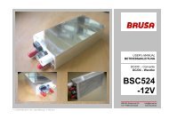
1. HV-Leistungsstecker<br />
2. Wasseranschlüsse<br />
3. Druckausgleichsmembran<br />
4. LV-Minuspol<br />
5. LV-Pluspol Leistungsstecker<br />
6. Steuerstecker<br />
7. Befestigungslöcher<br />
BSC623-12V-B_User_Manual_110531a.docx 8 / 51<br />
1<br />
2<br />
7<br />
6<br />
3<br />
5<br />
4<br />
1. HV-power connector<br />
2. Cooling pipes<br />
3. Pressure balance membrane<br />
4. LV-minus pole<br />
5. LV-plus pole power connector<br />
6. Control connector<br />
7. Mounting holes
<strong>Betriebsanleitung</strong> BSC623-12V-B User’s manual BSC623-12V-B<br />
4.2 Einführung<br />
Introduction<br />
4.3 Terminologie<br />
Terminology<br />
4.4 Elektrische Eckdaten<br />
Electrical parameters<br />
Der BSC623-12V ist ein bidirektionaler DC/DC-<br />
Wandler mit galvanischer Trennung zwischen dem<br />
Hochspannungs- und Niederspannungskreis. Das<br />
Gerät basiert zum einen auf einer serien-resonant<br />
arbeitenden Trafostufe, durch welche die galvanische<br />
Trennung realisiert wird. Zum anderen kann<br />
durch zwei zur Rippelreduzierung verzahnt arbeitende<br />
Hochsetz-/Tiefsetzsteller die gewünschte<br />
Spannung im jeweiligen Betriebsmodus eingestellt<br />
werden. Aufgrund der resonanten Topologie der<br />
Trafostufe und der sogenannten Autokommutierung<br />
des Hochsetz-/Tiefsetzstellers werden nicht nur<br />
Verluste auf ein Minimum begrenzt, sondern auch<br />
hervorragende EMV-Eigenschaften erreicht.<br />
Hochspannung, Leistungsanschluss (HV):<br />
Fuel Cell Circuit (FCC), Battery Circuit (BC)<br />
Niederspannung, Leistungsanschluss (LV):<br />
Bordnetz (AUX)<br />
Niederspannung, Steueranschluss (LV):<br />
Bordnetz (AUX)<br />
BSC623-12V-B_User_Manual_110531a.docx 9 / 51<br />
The BSC623-12V is a bidirectional DC/DCconverter<br />
with galvanic isolation between the high<br />
voltage and low voltage circuit. The device is based<br />
on one hand on a series-resonant operating transformer<br />
stage, which ensures the galvanic isolation.<br />
On the other hand two buck/boost-converters, that<br />
are operated interleaved in order to reduce ripple<br />
currents, enable to adjust the required voltage level<br />
in the corresponding operation mode. Due to the<br />
resonant topology of the transformer stage and the<br />
so-called Auto-Commutation of the buck/boostconverter<br />
not only losses are reduced to a minimum<br />
but also an excellent EMC-behavior is obtained.<br />
High voltage, Power interface (HV):<br />
Fuel cell circuit (FCC), Battery circuit (BC)<br />
Low voltage, Power interface (LV):<br />
Auxiliary system (AUX)<br />
Low voltage, Control interface (LV):<br />
Auxiliary system (AUX)<br />
Value Unit Bemerkung / Remarks<br />
Hochspannungsseite High voltage side<br />
Min. Spannung, eingeschränkte Leistung 170 V ULVmax = 14V Min. voltage, reduced performance<br />
Min. Spannung, volle Leistung 190 V Min. voltage, full performance<br />
Max. Spannung, volle Leistung 425 V Max. voltage, full performance<br />
Überspannung, Abschalten der Leistungsstufe >470 V Overvoltage, shut down of power stage<br />
Max. Spannung, kein Betrieb >600 V Gerät kann beschädigt werden / device may be Max. voltage, no operation<br />
damaged<br />
Verpolung Sicherung löst aus / fuse may blow Reverse polarity<br />
Niederspannungsseite Low voltage side<br />
Nennspannung 14.0 V +/-0.1V Rated voltage<br />
Min. Spannung, volle Leistung 8.0 V Min. voltage, full performance<br />
Max. Spannung, volle Leistung 16.0 V Max. voltage, full performance<br />
Überspannung, Abschaltung der Leistungsstufe >20.0 V Overvoltage, shut down of power stage<br />
Max. Spannung, kein Betrieb, max. 1min. >25.0 V Gerät kann beschädigt werden / device may be<br />
damaged<br />
Max. voltage, no operation, max. 1min.<br />
Verpolung Sicherung löst aus / fuse may blow Reverse polarity
<strong>Betriebsanleitung</strong> BSC623-12V-B User’s manual BSC623-12V-B<br />
Leistungsdaten Power rating<br />
LV-Dauerstrom 200 A Continuous LV current<br />
LV-Spitzenstrom 250 A Peak buck mode LV current<br />
HV-Dauerstrom Hochsetzbetrieb 3.6 A @ UHV = 400V, ULV = 8V, η = 90% Continuous boost mode HV current<br />
HV-Spitzenstrom Hochsetzbetrieb 4.5 A @ UHV = 400V, ULV = 8V, η = 90% Peak boost mode HV current<br />
Dauerleistung Tiefsetzbetrieb 2.8 kW @ Nennspannung / @ rated voltage Continuous buck mode output power<br />
Spitzenleistung Tiefsetzbetrieb 3.5 kW @ Nennspannung / @ rated voltage Peak buck mode output power<br />
Dynamisches Verhalten Dynamic performance<br />
Sprungantwort LV-Spannung
<strong>Betriebsanleitung</strong> BSC623-12V-B User’s manual BSC623-12V-B<br />
4.5 Mechanische Eckdaten<br />
Mechanical parameters<br />
Kühlung Thermal<br />
Kühlmedium 50% water, 50% ethylene glycol Coolant medium<br />
Kühlmittelvolumen 225 ml Inklusive Anschlussstutzen / Including nozzle Coolant volume<br />
Min. Kühlmitteltemperatur -40 °C Min. coolant temperature<br />
Max. Kühlmitteltemperatur 65 °C Max. coolant temperature<br />
Durchflussrate >4 l/min Cooling flow rate<br />
Druckabfall
<strong>Betriebsanleitung</strong> BSC623-12V-B User’s manual BSC623-12V-B<br />
5 Schnittstellen<br />
Interfaces<br />
5.1 Leistungsanschlüsse<br />
Power connectors<br />
1<br />
2<br />
3<br />
4<br />
5<br />
6<br />
Hochspannungs – Steckverbindung:<br />
Nr. Abk. Funktion<br />
1 IL1 Interlock<br />
2 IL2 Interlock<br />
3 HV+ Hochspannung Plus<br />
4 HV- Hochspannung Minus<br />
Niederspannungs – Steckverbindung:<br />
Beim LV-Pluspolstecker handelt es sich um einen<br />
sogenannten „Push-Pull-Stecker“. Um die Steckverbindung<br />
zu trennen, muss der Stecker vorgängig<br />
ganz hineingedrückt werden, bevor er dann herausgezogen<br />
werden kann.<br />
Nr. Abk. Funktion<br />
5 LV+ Bordnetz Plus<br />
6 LV- /<br />
PGND<br />
Interlock:<br />
Bordnetz Leistungsmasse / Fahrzeugmasse<br />
Mittels dieser Funktion kann überprüft werden, ob<br />
die Stecker ordnungsgemäss angeschlossen sind,<br />
sodass davon abhängig entsprechende Massnahmen<br />
ergriffen werden können:<br />
Durch die voreilenden Interlock-Kontakte wird<br />
beim Trennen der HV-Steckverbindung ein Fehler<br />
erkannt und das Gerät unmittelbar abgeschaltet,<br />
sodass ein möglicher Lichtbogen verhindert<br />
wird.<br />
Die Hochspannung im Gerät wird beim Erkennen<br />
einer getrennten HV-Steckverbindung unverzüglich<br />
mittels der ohnehin vorhandenen internen<br />
HV-Versorgung entladen (
<strong>Betriebsanleitung</strong> BSC623-12V-B User’s manual BSC623-12V-B<br />
5.2 Steueranschluss<br />
Control interface<br />
5.2.1 Pinbelegung des Steuersteckers<br />
Pin assignment of control connector<br />
1<br />
9<br />
16<br />
8<br />
15<br />
23<br />
Nr. Abk. Funktion<br />
1 GND Signalmasse (Bordnetzmasse, Klemme<br />
31)<br />
2 AUX +12V (Bordnetz Plus, Klemme 30)<br />
3 EN Enable (Power ON, Klemme 15)<br />
4 DO0 Digitaler Ausgang 1 (programmierbar)<br />
5 DO1 Digitaler Ausgang 2 (programmierbar)<br />
6 DO2 Digitaler Ausgang 3 (programmierbar)<br />
7 DO3 Digitaler Ausgang 4 (programmierbar)<br />
8 PG1 Analoge Masse (für Pins 21 – 23)<br />
9 CNL CAN Low<br />
10 CNH CAN High<br />
11 TXD RS232 Transmit (9-pol D-Sub: Pin 2)<br />
12 RXD RS232 Receive (9-pol D-Sub: Pin 3)<br />
13 PRO Enable Firmware-Programmierung<br />
14 PG2 Reserve-Masse<br />
15 PG3 RS232 Masse (9-pol D-Sub: Pin 5)<br />
16 DI0 Digitaler Eingang 1<br />
17 DI1 Digitaler Eingang 2<br />
18 DI2 Digitaler Eingang 3<br />
19 IL1 Interlock - Signaleinspeisung<br />
20 IL2 Interlock - Signaleinspeisung<br />
21 AI1 Analoger Eingang 1 (programmierbar)<br />
22 AI2 Analoger Eingang 2 (programmierbar)<br />
23 AI3 Analoger Eingang 3 (programmierbar)<br />
BSC623-12V-B_User_Manual_110531a.docx 13 / 51<br />
Nr. Abbr. Function<br />
1 GND Signal ground (Auxiliary system ground,<br />
terminal 31)<br />
2 AUX +12V (Auxiliary system plus, terminal<br />
30)<br />
3 EN Enable (Power ON, terminal 15)<br />
4 DO0 Digital output 1 (programmable)<br />
5 DO1 Digital output 2 (programmable)<br />
6 DO2 Digital output 3 (programmable)<br />
7 DO3 Digital output 4 (programmable)<br />
8 PG1 Analog ground (for pins 21 – 23)<br />
9 CNL CAN low<br />
10 CNH CAN high<br />
11 TXD RS232 transmit (9-pole D-Sub: Pin 2)<br />
12 RXD RS232 receive (9-pole D-Sub: Pin 3)<br />
13 PRO Enable firmware download<br />
14 PG2 Reserve ground<br />
15 PG3 RS232 ground (9-pole D-Sub: Pin 5)<br />
16 DI0 Digital input 1<br />
17 DI1 Digital input 2<br />
18 DI2 Digital input 3<br />
19 IL1 Interlock – Signal input<br />
20 IL2 Interlock - Signal input<br />
21 AI1 Analog Input 1 (programmable)<br />
22 AI2 Analog Input 2 (programmable)<br />
23 AI3 Analog Input 2 (programmable)
<strong>Betriebsanleitung</strong> BSC623-12V-B User’s manual BSC623-12V-B<br />
5.2.2 Beschreibung der Steuersteckerpins<br />
Description of the control connector<br />
pins<br />
5.2.2.1 GND (Masse, Ground), Pin 1 Direkte Verbindung zur Masse der Steuereinheit.<br />
Interne Beschaltung<br />
Internal Circuit<br />
GND (1)<br />
Gehäuse/housing<br />
5.2.2.2 AUX (Bordnetz, Auxiliary System),<br />
Pin 2<br />
Interne Beschaltung<br />
Internal Circuit<br />
AUX (2) 100uH 1.5A<br />
1.76uF<br />
36V<br />
14.1uF<br />
10.7V<br />
Supply<br />
11.3V<br />
Supply<br />
1MΩ<br />
23.5μF<br />
12.5V<br />
12.5V- HV<br />
Supply<br />
5V<br />
Supply<br />
5V<br />
Die Signalmasse ist nur kapazitiv mit dem Gehäuse<br />
verbunden, d.h. die Signalmasse ist von der Leistungsmasse<br />
(Gehäuse) galvanisch getrennt, um<br />
Masseschleifen zu vermeiden.<br />
Bei Verdrahtung von BSC623-12V-Steuersignalen<br />
mit anderen Fahrzeug-Komponenten (z.B. Fahrantrieb,<br />
Bordbatterie, Batteriemanagement, Brennstoffzelle)<br />
muss hier die Fahrzeug-Masse angeschlossen<br />
werden.<br />
Das Gerät wird – wenn keine Spannung am HV-<br />
Leistungsstecker anliegt – über diesen Anschluss<br />
vom Bordnetz versorgt. Dann kann mit EN = „High“<br />
über CAN oder RS232 mit dem Gerät kommuniziert<br />
werden. Folgende Funktionen sind bei ausschliesslicher<br />
Versorgung vom Bordnetz (Steuerstecker) sichergestellt:<br />
Senden und Empfangen von CAN-Nachrichten<br />
Kommunikation über RS232 (Monitor-<br />
Programm)<br />
Programmieren der Firmware<br />
Spannungs-, Strom- und Temperaturmessung<br />
BSC623-12V-B_User_Manual_110531a.docx 14 / 51<br />
Direct connection to control unit ground.<br />
The signal ground is coupled capacitively only to<br />
the housing, which means the signal ground is galvanically<br />
isolated from the power ground (housing),<br />
in order to avoid ground loops.<br />
If BSC623-12V control signals are connected to<br />
other vehicle components (e.g. propulsion system,<br />
on-board battery, battery management system, fuel<br />
cell) the vehicle’s ground must be connected to this<br />
terminal.<br />
The device will be supplied – if no voltage is applied<br />
to the HV-power connector – by the auxiliary system.<br />
Communication over CAN or RS232 can be<br />
enabled by setting EN = “high”. If only auxiliary system<br />
(control connector) is applied, following functions<br />
are available:<br />
Send and receive CAN-messages<br />
Communication via RS232 (monitor-program)<br />
Download of firmware<br />
Voltage and temperature measurement<br />
Spannung an AUX (2) in V Enable (3), RUN-Command (über HV-Spannung Stromaufnahme an<br />
Klemme 15 CAN gesendet) in V<br />
AUX (2) in mA<br />
Voltage at AUX (2) in V Enable (3), RUN-Command (sent HV-voltage in V Current consumption<br />
Terminal 15 by CAN)<br />
at AUX (2) in mA<br />
12.0 0 0 0 0.0559<br />
14.0 0 0 0 0.0578<br />
12.0 1 0 0 250.8000<br />
14.0 1 0 0 220.2000<br />
12.0 1 0 330 10.7200<br />
14.0 1 0 330 14.1800
<strong>Betriebsanleitung</strong> BSC623-12V-B User’s manual BSC623-12V-B<br />
5.2.2.3 EN (Enable, Power ON), Pin 3 Bei Anlegen einer Spannung an AUX und mit EN =<br />
Interne Beschaltung<br />
Internal Circuit<br />
EN (3)<br />
47nF<br />
33V<br />
11.3V Supply<br />
Enable<br />
120kΩ<br />
2.7kΩ<br />
11.3V<br />
Supply<br />
100nF<br />
2.7kΩ<br />
5V<br />
Supply<br />
100nF<br />
5V Supply<br />
Enable<br />
23.5kΩ<br />
220pF<br />
22kΩ<br />
5V<br />
1,0V<br />
3,3V<br />
Schmitt<br />
Trigger<br />
„High“ (+7V...32V) wird das Gerät in den betriebsbereiten<br />
Modus versetzt. Sinnvollerweise erfolgt<br />
dies durch eine Verbindung des Enable-Pins über<br />
einen Schalter mit dem Bordnetz Plus.<br />
Um eine neue Firmware zu programmieren, ist es<br />
nicht erforderlich, dass EN = „High“ ist.<br />
Auch wenn am HV-Stecker Hochspannung anliegt,<br />
wird die geräteinterne Logik nur dann versorgt,<br />
wenn der Pin EN = „High“ ist (oder Pin PROG =<br />
„High“ ist).<br />
BSC623-12V-B_User_Manual_110531a.docx 15 / 51<br />
By applying voltage at AUX and by setting EN =<br />
„high” (+7V...32V) the device will be ready to operate.<br />
Reasonably this is realized by using a switch in<br />
order to connect the enable-pin to the auxiliary system<br />
plus.<br />
In order to download a new firmware, EN does not<br />
have to be „high”.<br />
Even when high voltage is applied to the HVconnector,<br />
the device internal logic is only supplied,<br />
if the pin EN = „high“ (or pin PROG = “high”).
<strong>Betriebsanleitung</strong> BSC623-12V-B User’s manual BSC623-12V-B<br />
5.2.2.4 DO0 – DO3 (Digitale Ausgänge, Digital<br />
Outputs), Pins 3 - 7<br />
Interne Beschaltung<br />
Internal Circuit<br />
DO0 - DO3 (4 - 7)<br />
10nF<br />
33V<br />
500Ω<br />
AUX<br />
Mit diesen vier programmierbaren digitalen Ausgängen<br />
können optional niederfrequente Anwendungen<br />
realisiert werden:<br />
Ansteuerung von LEDs für Statusfunktionen<br />
(z.B. Unter- bzw. Überspannung, Überschreitung<br />
einer Stromgrenze, Temperaturrückreglung,...).<br />
Ansteuerung von anderen externen Komponenten<br />
(PWM für Anzeigeinstrumente, Relais, kleine<br />
Lüfter,...).<br />
Alle vier digitalen Ausgänge weisen folgende<br />
Merkmale auf:<br />
RDSON = 1,7Ω bei Ta = 25°C<br />
VOUTmax = 32V<br />
VCLAMP 45V (Spannungsfestigkeit für induktive<br />
Lasten)<br />
Kurzschlussfestigkeit (Imax = 700mA)<br />
Abschaltung bei zu hoher Temperatur aufgrund<br />
von Überbelastung<br />
Bei Auftreten eines Fehlers an einem Ausgang sind<br />
die restlichen Ausgänge weiter funktionstauglich,<br />
wenn es durch den einen Fehler nicht zu einer Abschaltung<br />
bei den restlichen Ausgängen aufgrund<br />
zu hoher Temperatur führt.<br />
Die Ausgänge können mit Frequenzen bis zu 10kHz<br />
betrieben werden. Um auch bei diesen Frequenzen<br />
noch ordentliche Signalverläufe zu ermöglichen, ist<br />
jeder Ausgang mit einem 500Ω/2W Pull-up-<br />
Widerstand beschaltet.<br />
BSC623-12V-B_User_Manual_110531a.docx 16 / 51<br />
With these four programmable digital outputs low<br />
frequency applications can be realized optionally:<br />
Drive LEDs for status functions (e.g.: under- or<br />
overvoltage, exceeding of current limit, temperature<br />
derating,...).<br />
Drive other external components (PWM for display<br />
instruments, relays, small fans,...).<br />
All four digital outputs show the following features:<br />
RDSON = 1,7Ω at Ta = 25°C<br />
VOUTmax = 32V<br />
VCLAMP 45V (clamping voltage for inductive<br />
loads)<br />
Short circuit detection (Imax = 700mA)<br />
Over-temperature shutdown due to overload<br />
In case of such a failure at one of the outputs the<br />
other outputs remain still fully functional as long as<br />
such a failure does not lead to over-temperature<br />
shut down of the other outputs.<br />
All outputs can be driven with a frequency up to<br />
10kHz. In order to ensure proper signals even at<br />
such frequencies, each output has a 500Ω/2W pullup<br />
resistor.
<strong>Betriebsanleitung</strong> BSC623-12V-B User’s manual BSC623-12V-B<br />
5.2.2.5 PG1 – PG3 (Analoge Masse, Analog<br />
Ground), Pins 8, 14, 15<br />
Interne Beschaltung<br />
Internal Circuit<br />
PG1 – PG3 (8, 14, 15)<br />
(1)<br />
5.2.2.6 CNH, CNL (CAN-BUS, CAN-<br />
Interface), Pins 9, 10<br />
Interne Beschaltung<br />
Internal Circuit<br />
CNH (10)<br />
CNL (9)<br />
47pF<br />
47pF<br />
33V<br />
33V<br />
51uH<br />
51uH<br />
120Ω<br />
Termination<br />
resistor is<br />
optional<br />
300mA<br />
CAN-Transceiver<br />
and galvanic<br />
isolation<br />
4.7μF<br />
Zur Vereinfachung der externen Verdrahtung stehen<br />
drei zusätzliche Masse-Anschlüsse zur Verfügung.<br />
Diese sind über je eine PTC-Sicherung mit<br />
der Versorgungs-Masse GND verbunden.<br />
Folgende Zuordnung wird vorgeschlagen:<br />
Nr. Abk. Funktion<br />
8 PG1 Analoge Masse (für Pins 21 - 23)<br />
14 PG2 Reserve Masse<br />
15 PG3 RS232 - Masse (9-pol D-Sub: Pin 5)<br />
Die CAN-Schnittstelle weist folgende Eigenschaften<br />
auf:<br />
CAN 2.0 B, 500 kBit (Standard)<br />
Die CAN-Schnittstelle weist eine Potentialtrennung<br />
von der Masse und den übrigen Steuersignalen<br />
auf, um Störungen durch Potentialverschiebungen<br />
zu vermeiden.<br />
Der 120Ω Abschlusswiderstand kann durch<br />
BRUSA auf Wunsch bestückt werden. Diese Information<br />
muss bei der Bestellung angeführt<br />
werden.<br />
Über die CAN-Schnittstelle können Informationen<br />
gemäss der seitens BRUSA als dbc-Datei<br />
zur Verfügung gestellten CAN-Matrix gesendet<br />
und empfangen werden.<br />
Die Identifier der jeweiligen Nachricht, die Baudrate<br />
als auch der Abtastpunkt für die CAN-<br />
Signale können optional durch das PARAM-<br />
Tool verändert werden.<br />
BSC623-12V-B_User_Manual_110531a.docx 17 / 51<br />
In order to simplify external wiring, three additional<br />
ground pins are available. Each pin is connected to<br />
the supply’s ground GND by a PTC-fuse.<br />
Following pin assignment is suggested:<br />
No. Abbr. Function<br />
8 PG1 Analog ground (for pins 21 - 23)<br />
14 PG2 Reserve ground<br />
15 PG3 RS232 - ground (9-pol D-Sub: Pin 5)<br />
The CAN interface has following characteristics:<br />
CAN 2.0 B, 500 kBit (default)<br />
Galvanic isolation from ground and all other<br />
control signals in order to avoid interferences<br />
caused by ground offset voltages.<br />
The 120Ω termination resistor can be mounted<br />
by BRUSA if desired. This information must be<br />
included in the order.<br />
The CAN interface allows to transmit and receive<br />
messages according to the CAN-matrix<br />
provided by BRUSA, which is available as dbcfile.<br />
The identifiers of each message, the baud rate<br />
as well as the sampling point of the CAN-signals<br />
can be modified optionally by the PARAM-tool.
<strong>Betriebsanleitung</strong> BSC623-12V-B User’s manual BSC623-12V-B<br />
5.2.2.7 TXD, RXD (RS232-Schnittstelle,<br />
RS232-Interface), Pins 11, 12<br />
Interne Beschaltung<br />
Internal Circuit<br />
TXD (11)<br />
RXD (12)<br />
470pF<br />
470pF<br />
33V<br />
33V<br />
100Ω<br />
100Ω<br />
15V<br />
10V<br />
200Ω<br />
200Ω<br />
470pF<br />
470pF<br />
RS232-<br />
Transeiver<br />
Die RS232-Schnittstelle ermöglicht eine direkte serielle<br />
Verbindung zwischen dem BSC623-12V und<br />
einem Computer. Gerade für Prüfstände oder Prototypenfahrzeuge<br />
empfehlen wir unbedingt die Verdrahtung<br />
der RS232-Schnittstelle, um im Bedarfsfall<br />
ein Firmware-Update durchführen zu können. Folgende<br />
Funktionen stehen zur Verfügung:<br />
Programmieren der von BRUSA mitgelieferten<br />
oder nachgereichten Firmware (durch Setzen<br />
von PRO = „High“). Für weitere Informationen<br />
zum Programmieren kontaktieren Sie bitte direkt<br />
BRUSA.<br />
Anzeige der Momentanwerte von Strom, Spannung<br />
und Temperatur. Die dafür notwendige<br />
Software „HyperTerminal“ ist prinzipiell auf jedem<br />
Windows-Computer unter „Programme →<br />
Zubehör → Kommunikation“ bereits verfügbar.<br />
Bitte beachten Sie, dass diese Funktionalität<br />
neuerdings durch das sogenannte über CAN<br />
laufende PARAM-Tool wesentlich komfortabler<br />
abgedeckt wird.<br />
Belegung der 9-poligen D-Sub Kabelbuchse:<br />
TXD (11)<br />
RXD (12)<br />
PG3 (15) 5<br />
9-polige D-Sub<br />
Kabelbuchse<br />
Transceiver<br />
BSC623-12V-B_User_Manual_110531a.docx 18 / 51<br />
2<br />
3<br />
The RS232 interface provides a direct serial connection<br />
between the BSC623-12V and a computer<br />
Especially for test benches or prototype vehicles we<br />
strongly recommend to wire the RS232-interface, in<br />
order to make a firmware-update if necessary. Following<br />
functions are provided:<br />
Download the firmware provided by BRUSA (by<br />
setting PRO = “high”). For further information<br />
regarding the download please contact directly<br />
BRUSA.<br />
Display the actual current, voltage and temperature<br />
values (monitor program). The required<br />
software “HyperTerminal” is basically available<br />
on every Windows-Computer under “Programs<br />
→ Accessories → Communication”. Please take<br />
note that this feature will be newly covered by<br />
the over CAN operated so-called PARAM-tool<br />
which is much more convenient.<br />
Pin assignment of the 9-pole D-sub socket:<br />
TXD (11)<br />
RXD (12)<br />
2<br />
3<br />
PG3 (15) 5<br />
9 pin D-Sub<br />
connector, female<br />
Kabelbuchse<br />
Transceiver
<strong>Betriebsanleitung</strong> BSC623-12V-B User’s manual BSC623-12V-B<br />
5.2.2.8 PRO (Enable Firmware Programmierung,<br />
Enable firmware download),<br />
Pin 13<br />
Interne Beschaltung<br />
Internal Circuit<br />
PRO (13)<br />
47nF<br />
33V<br />
11.3V Supply<br />
Enable<br />
120kΩ<br />
2.7kΩ<br />
11.3V<br />
Supply<br />
100nF<br />
2.7kΩ<br />
5V<br />
Supply<br />
5V Supply<br />
Enable<br />
220pF<br />
5V<br />
1,0V<br />
3,3V<br />
Schmitt<br />
Trigger<br />
5.2.2.9 DI0 – DI2 (Digitale Eingänge, Digital<br />
Inputs), Pins 16 – 18<br />
Interne Beschaltung<br />
Internal Circuit<br />
DI0 – DI2 (16 - 18)<br />
10nF<br />
33V<br />
23.5kΩ<br />
22kΩ<br />
220pF<br />
100nF<br />
23.5kΩ<br />
22kΩ<br />
5V<br />
1,0V<br />
3,3V<br />
Schmitt<br />
Trigger<br />
uC<br />
Dieser Anschluss wird ausschliesslich für das Programmieren<br />
einer neuen Firmware aktiviert (PRO =<br />
„High“), wobei dann EN nicht „High“ sein muss.<br />
Sowohl bei Versorgung von Hochspannung als<br />
auch vom Bordnetz löst PRO = „High“ folgende<br />
Vorgänge aus:<br />
Falls das Gerät im Betrieb ist, wird dieser gestoppt.<br />
Das Gerät ist dann empfangsbereit und kann<br />
über die serielle Schnittstelle programmiert werden.<br />
Das Programmieren einer neuen Firmware darf nur<br />
in Absprache mit BRUSA durchgeführt werden. Die<br />
Firmware wird dann allenfalls per Email zugestellt.<br />
Mit diesen drei Eingängen können optional verschiedene<br />
Funktionen realisiert werden wie folgender<br />
Vorschlag zeigt:<br />
DI0: Hochsetzbetrieb<br />
DI1: Tiefsetzbetrieb<br />
DI2: Spannungs- oder Stromregelmodus<br />
BSC623-12V-B_User_Manual_110531a.docx 19 / 51<br />
This pin is exclusively activated (PRO = „high“) to<br />
download a new firmware, whereas EN does not<br />
have to be „high”.<br />
PRO = „high” causes the following actions regardless<br />
of supplying the device from high voltage or<br />
auxiliary system:<br />
If the device is in operation, it will be shut down.<br />
The device is then ready to be programmed via<br />
the serial interface.<br />
The download of a new firmware may only be done<br />
with agreement of BRUSA. A new firmware can be<br />
provided by email then.<br />
With these three inputs various functions can be realized<br />
optionally as the following proposal shows:<br />
DI0: Boost mode<br />
DI1: Buck mode<br />
DI2: Voltage or current regulation mode
<strong>Betriebsanleitung</strong> BSC623-12V-B User’s manual BSC623-12V-B<br />
5.2.2.10 IL1, IL2 (Interlock), Pins 19, 20 Der Interlock ist eine sicherheitsrelevante Funktion,<br />
die intern verarbeitet wird, aber auch durch ein<br />
Interne Beschaltung<br />
Internal Circuit<br />
IL2 (20)<br />
IL1 (19)<br />
10nF<br />
10nF<br />
12mH<br />
12mH<br />
10uF<br />
30kΩ<br />
R4<br />
62Ω<br />
100nF<br />
470pF<br />
IL2 (2)<br />
IL1 (1)<br />
470pF<br />
51uH<br />
51uH<br />
5V<br />
High voltage<br />
power connector<br />
Interlock-Error<br />
(INTL_OC_ext*)<br />
Int. Interlock<br />
Processing<br />
(INTL_OC_int*)<br />
übergeordnetes System (Bsp.: Fahrzeugsystem)<br />
ausgewertet werden kann. Die Interlockverbindung<br />
ist durch die HV-Steckverbindung geschleift (Brücke<br />
im kundenseitigen HV-Stecker) und erlaubt so die<br />
Überprüfung, ob dieser Stecker ordnungsgemäss<br />
angeschlossen ist. Das Gerät verfügt über zwei unabhängige<br />
Interlocküberwachungsschaltungen:<br />
Interne Interlockerkennung<br />
Externe Interlockerkennung<br />
Die interne Interlockerkennung funktioniert unabhängig<br />
von der Verwendung der externen Erkennung<br />
und überwacht ausschliesslich, ob der HV-<br />
Stecker richtig angeschlossen ist. Bei einem Fehler<br />
wird das Signal INTL_OC_int* gesetzt und über<br />
CAN der Fehler „CRE_INTERLOCK“ ausgegeben.<br />
Aus Sicherheitsgründen kann die interne Interlockerkennung<br />
nicht deaktiviert werden.<br />
Durch Verwendung der externen Interlockerkennung<br />
kann nicht nur die eigene HV-Steckverbindung,<br />
sondern auch jene von zusätzlichen Geräten<br />
überprüft werden.<br />
Hierfür muss durch den Kunden das Interlocksignal<br />
in Form eines DC-Stroms von mindestens<br />
20mA bei Pin 19 bzw. 20 eingespeist<br />
werden, wobei die Polarität keine Rolle spielt.<br />
Im PARAM-Tool überprüfen, ob die externe Interlockerkennung<br />
tatsächlich aktiviert ist und<br />
gegebenenfalls korrigieren.<br />
Falls nun irgendeine der überwachten Steckverbindungen<br />
nicht richtig kontaktiert ist, ist die<br />
Schleife offen und der eingeprägte Strom kann<br />
nicht mehr fliessen. Bei Unterschreiten einer<br />
Schwelle von ca. 15mA wird das Signal<br />
INTL_OC_ext* gesetzt und über CAN der Fehler<br />
„CRE_INTERLOCK“ ausgegeben.<br />
BSC623-12V-B_User_Manual_110531a.docx 20 / 51<br />
The interlock is a safety relevant function, which is<br />
processed internally but may also be evaluated by a<br />
superior system (e.g.: vehicle system). The interlock<br />
is looped through the HV-connection (wire link in<br />
customer side HV-connector) and allows therefore<br />
to monitor if this connector is connected properly to<br />
the device. The device offers two independently operating<br />
interlock monitoring circuits:<br />
Internal interlock detection<br />
External interlock detection<br />
The internal interlock detection operates independently<br />
of the usage of the external interlock detection<br />
and monitors exclusively, if the HVconnector<br />
is plugged in properly. In case of a failure<br />
the signal INTL_OC_int* is set and the error<br />
„CRE_INTERLOCK“ is sent by CAN. Due to safety<br />
reasons the internal interlock detection cannot be<br />
deactivated.<br />
The usage of the external interlock detection allows<br />
to not only monitor the own HV-connection but<br />
also those of additional devices.<br />
For this purpose the customer must inject the interlock<br />
signal in form of a DC-current of minimum<br />
20mA at pin 19, resp. 20, whereas the polarity<br />
does not matter.<br />
Check in the PARAM-tool, whether the external<br />
interlock detection is actually activated and correct<br />
if necessary.<br />
If now any of the monitored connections is not<br />
connected properly to the device, the loop is<br />
open and the injected current may not flow.<br />
When the current falls below a level of app.<br />
15mA, the signal INTL_OC_ext* is set and the<br />
error „CRE_INTERLOCK“ is sent by CAN.
<strong>Betriebsanleitung</strong> BSC623-12V-B User’s manual BSC623-12V-B<br />
5.2.2.11 AI1 – AI3 (Analoge Eingänge, Analog<br />
Inputs), Pins 21 – 23<br />
Interne Beschaltung<br />
Internal Circuitp<br />
AI1 – AI3 (21 - 23)<br />
10nF<br />
I = 1mA<br />
10nF<br />
150Ω<br />
33kΩ<br />
5V<br />
Analog<br />
Multiplexer<br />
22kΩ<br />
5V<br />
Analog<br />
Multiplexer<br />
uC<br />
Die Erkennung des internen und externen Interlockfehlers<br />
– vorausgesetzt der letztere ist überhaupt<br />
aktiviert – führt unverzüglich zum Abschalten des<br />
Geräts.<br />
Mit Hilfe des PARAM-Tools kann aufgeschlüsselt<br />
werden, ob ein vorliegender Interlockfehler durch<br />
die interne oder externe Erkennung detektiert wurde.<br />
Die LV-Steckverbindung ist im Interlockkreis nicht<br />
integriert!<br />
Die im kundenseitigen HV-Stecker bereits bestückte<br />
Drahtbrücke darf keinesfalls entfernt<br />
oder abgeändert (z.B. verlängert) werden!<br />
Mit diesen drei analogen Eingängen können optional<br />
jeweils zwei unterschiedliche Funktionen realisiert<br />
werden:<br />
1mA – Stromquelle für externes 5kΩ Potentiometer<br />
33kΩ Pull-up – Widerstand für externen 33kΩ<br />
NTC-Temperatursensor.<br />
Jeder der drei analogen Eingänge kann individuell<br />
gemäss Kundenanforderung programmiert werden.<br />
Bei der Einstellung aller drei Eingänge als Stromquelle<br />
können z.B. folgende Funktionen realisiert<br />
werden:<br />
AI1: Spannungsregelung LV<br />
AI2: Stromlimit Buck-Mode<br />
AI3: Stromlimit Boost-Mode<br />
Bei der Einstellung zur Temperaturmessung (Tmin =<br />
25°C) von externen Komponenten ist z.B. folgende<br />
Konfiguration möglich:<br />
AI1: Batterietemperatur<br />
AI2: Kühlwassertemperatur<br />
AI3: Reserve<br />
BSC623-12V-B_User_Manual_110531a.docx 21 / 51<br />
The detection of an internal and external interlock<br />
failure – presumed the latter one is activated in fact<br />
– results in immediate shut-down of the device.<br />
By means of the PARAM-tool it is possible to diagnose<br />
whether an interlock failure was detected by<br />
the internal or the external detection.<br />
The LV-connection is not integrated in the interlockcircuit!<br />
The wire link in the customer side HV-connector<br />
must not be removed or changed (for instance to<br />
lengthen) in any way!<br />
With each of these three analog inputs two different<br />
functions can be realized optionally:<br />
1mA – current source for an external 5kΩ potentiometer<br />
33kΩ pull-up – resistor for external 33kΩ NTCtemperature<br />
sensor.<br />
Each of these three analog inputs can be programmed<br />
individually according to the customer’s<br />
requirements. If all three inputs are configured as<br />
current source, the following functions can be realized:<br />
AI1: Voltage regulation LV<br />
AI2: Current limit buck-mode<br />
AI3: Current limit boost-mode<br />
If the inputs are configured for temperature measurement<br />
(Tmin = 25°C) of external components, the<br />
following configuration is proposed:<br />
AI1: Battery temperature<br />
AI2: Cooling water temperature<br />
AI3: Reserve
<strong>Betriebsanleitung</strong> BSC623-12V-B User’s manual BSC623-12V-B<br />
6 Technische Eigenschaften<br />
Technical characteristics<br />
6.1 Interne Stromversorgungen<br />
Internal power supplies<br />
AUX (2) 100uH 1.5A<br />
GND (1)<br />
BSC623-12V-B_User_Manual_110531a.docx 22 / 51<br />
EN (3)<br />
PRO (13)<br />
1.76uF<br />
47nF<br />
33V<br />
47nF<br />
33V<br />
36V<br />
14.1uF<br />
120kΩ<br />
2.7kΩ<br />
10.7V/0.1A<br />
Supply<br />
11.3V/1A<br />
Supply<br />
Das Gerät kann prinzipiell sowohl von HV als auch<br />
von AUX (2) versorgt werden, wobei für die vollständige<br />
Betriebsbereitschaft die 12.5V/2.5A-<br />
Versorgung aktiv sein muss. Diese läuft bei einer<br />
HV-Spannung von etwa 75V an und deaktiviert<br />
durch die höhere Ausgangsspannung automatisch<br />
die 11.3V/1A-Versorgung von AUX (2), um den<br />
Stromverbrauch ab Bordnetz zu reduzieren.<br />
100nF<br />
HV<br />
12.5V/2.5A<br />
Supply<br />
11.3V Supply<br />
Enable<br />
2.7kΩ<br />
5V/1A<br />
Supply<br />
100nF<br />
5V Supply<br />
Enable<br />
5V-CAN<br />
Supply<br />
+6V/0.1A<br />
Supply<br />
-6V/0.1A<br />
Supply<br />
10kΩ<br />
Driver<br />
Galvanically<br />
isolated<br />
CAN supply<br />
Controller<br />
PWM-Unit<br />
Regulation &<br />
measurement<br />
circuits<br />
uC-Enable 1<br />
The device can be supplied from HV as well as from<br />
AUX (2), whereas for the complete ready status the<br />
12.5V/2.5A-supply has to be active. This supply<br />
starts operating at a HV-voltage of approximately<br />
75V and automatically deactivates then due to the<br />
higher output voltage the 11.3V/1A-supply from<br />
AUX (2), in order to reduce the current consumption<br />
from the auxiliary system.
<strong>Betriebsanleitung</strong> BSC623-12V-B User’s manual BSC623-12V-B<br />
Die 5V-Versorgung wird erst gewährleistet, wenn<br />
entweder EN (3) oder PRO (13) mit AUX (2) verbunden<br />
wird. Die für den uC über Enable1 hardwaremässig<br />
vorgesehene Selbsthaltefunktion ist<br />
aus Sicherheitsgründen softwareseitig deaktiviert.<br />
Um optional einen autarken Betrieb des Geräts gewährleisten<br />
zu können, ist eine 10.7V/0.1A-<br />
Versorgung implementiert. Auf diese Weise kann<br />
beispielsweise EN (3) durch eine Verbindung mit<br />
AUX (2) im kundenseitigen Stecker aktiviert werden,<br />
sodass das Gerät immer eingeschaltet ist.<br />
Die 12.5V/2.5A-Versorgung ist ebenfalls mit der –<br />
auch im Hoch-/Tiefsetzsteller eingesetzten – Autokommutierung-Topologie<br />
realisiert. Diese Speisung<br />
ist galvanisch vom Hochspannungskreis getrennt<br />
und funktioniert zudem ohne Optokoppler.<br />
Im Hochsetzstellbetrieb werden die Treiber beim<br />
Hochstarten zu Beginn von AUX (2) versorgt.<br />
Sämtliche Versorgungsschaltkreise sind kurzschlussfest.<br />
Die Signalmasse GND (1) ist von der Leistungsmasse<br />
PGND galvanisch getrennt, um Potentialverschleppungen<br />
bzw. Masseschleifen zu verhindern.<br />
BSC623-12V-B_User_Manual_110531a.docx 23 / 51<br />
The 5V-supply will be provided, if either EN (3) or<br />
PRO (13) will be connected to AUX (2). On hardware<br />
level Enable 1 features a self-sustaining function<br />
for the uC, which is however deactivated due to<br />
safety reasons.<br />
A 10.7V/0.1A-supply is implemented, in order to<br />
enable an optional autarkic operation of the device.<br />
Thus, EN (3) for instance could be activated by a<br />
connection to AUX (2) in the customer-side connector,<br />
so that the device will be permanently<br />
switched on.<br />
The 12.5V/2.5A-supply is realized again with the –<br />
also in the buck/boost converter used – Auto-<br />
Commutation-topology. This supply is galvanically<br />
isolated from the high voltage circuit and furthermore<br />
functions without an optocoupler.<br />
In boost mode the drivers will be supplied from AUX<br />
(2) in the very beginning of the start-up.<br />
All supply circuits are short-circuit-proof.<br />
The signal ground GND (1) is galvanically isolated<br />
from the power ground PGND, in order to avoid accidental<br />
potential transfer, resp. ground loops.
<strong>Betriebsanleitung</strong> BSC623-12V-B User’s manual BSC623-12V-B<br />
6.2 Schutzfunktionen<br />
Safety functions<br />
6.2.1 Überlastschutz – Derating<br />
Overload protection – derating<br />
Rückregelung aufgrund Trafotemperatur<br />
Derating due to transformer temperature<br />
ILVmax/A<br />
250<br />
104 106<br />
-10A/°C<br />
129 131<br />
T/°C<br />
Rückregelung aufgrund Schaltertemperatur<br />
der Trafostufe<br />
Derating due to switch temperature of<br />
transformer stage<br />
ILVmax/A<br />
250<br />
95<br />
-10A/°C<br />
120<br />
T/°C<br />
Abschalten aufgrund Schaltertemperatur<br />
von Hoch-/Tiefsetzsteller<br />
Shut down due to temperature of buck/boost<br />
switch<br />
ILVmax/A<br />
250<br />
80 81<br />
T/°C<br />
Um das Gerät vor Überlast zu schützen, wird die<br />
Temperatur von bestimmten Bauteilen erfasst, sodass<br />
bei Erreichen eines definierten Werts automatisch<br />
der maximal mögliche Strom zurückgeregelt<br />
oder das Gerät abgeschaltet wird. Hierfür stehen 8<br />
verschiedene Temperatursensoren zur Verfügung,<br />
die sich in 4 Sensorgruppen gliedern:<br />
Schalter des Hoch-/Tiefsetzstellers: 2 Sensoren<br />
Schalter der HV-seitigen Trafostufe: 2 Sensoren<br />
Schalter der LV-seitigen Trafostufe: 2 Sensoren<br />
Wicklung der beiden HF-Leistungstransformatoren:<br />
Jeweils 1 Sensor<br />
Von den oben aufgeführten Sensorgruppen werden<br />
nur folgende für die Rückregelung des maximal<br />
möglichen Stroms verwendet:<br />
Schalter der HV-seitigen Trafostufe<br />
Schalter der LV-seitigen Trafostufe<br />
Wicklung der beiden HF-Leistungstransformatoren<br />
Aufgrund der niedrigen Verluste der Schalter des<br />
Hoch-/Tiefsetzstellers sowie der effizienten Kühlung<br />
weisen die zwei entsprechenden gemessenen<br />
Temperaturwerte nur eine geringfügig höhere Temperatur<br />
gegenüber jener der Kühlflüssigkeit auf.<br />
Daher geben diese Messwerte auch Aufschluss<br />
über die im Gerät vorherrschende Umgebungstemperatur.<br />
Damit Bauteile keinen Schaden nehmen<br />
können bzw. deren Lebensdauer nicht negativ beeinflusst<br />
wird, bewirkt diese Sensorgruppe, dass<br />
das Gerät bei einer Temperatur von 81°C abschaltet.<br />
Erst, wenn die Temperatur wieder unter 80°C<br />
sinkt, ist das Gerät wieder betriebsbereit.<br />
Da über die CAN-Schnittstelle der aktuell transferierbare<br />
Strom „LVCUR_AVL“ zurückgemeldet wird,<br />
ist erkennbar, ob das Gerät im Rückregelmodus ist.<br />
Wenn das Gerät aufgrund zu hoher Temperaturen<br />
schlussendlich abschaltet, wird der Fehler<br />
„E_OVERTEMP“ ausgegeben.<br />
BSC623-12V-B_User_Manual_110531a.docx 24 / 51<br />
In order to protect the device in case of overload,<br />
the temperature of specific components is monitored,<br />
so that as soon as a certain value is reached,<br />
the maximum available current will be automatically<br />
derated or the device will be switched off. For this<br />
purpose there are 8 different temperature sensors<br />
provided that are organized to 4 sensor groups:<br />
Switch of buck/boost stage: 2 sensors<br />
Switch of HV-side transformer stage: 2 sensors<br />
Switch of LV-side transformer stage: 2 sensors<br />
Coil of both HF-power transformers: One sensor<br />
for each transformer<br />
Of the above shown sensor groups only the following<br />
are in fact used for the derating of the maximum<br />
available current:<br />
Switch of HV-side transformer stage<br />
Switch of LV-side transformer stage<br />
Coil of both HF-power transformers<br />
Due to the low losses of the switches of the<br />
buck/boost-converter as well as due to the efficient<br />
cooling, the two corresponding measured temperature<br />
values show only a little higher temperature referred<br />
to that of the coolant. Therefore these measurement<br />
values give information about the predominating<br />
ambient temperature inside the device. In order<br />
to protect components from damage, respectively<br />
to avoid negative impact on their lifetime, this<br />
sensor group causes the device to be shut down at<br />
a temperature of 81°C. Only, when the temperature<br />
drops below 80°C, the device is ready for operation<br />
again.<br />
Since the actual available current that can be transferred<br />
“LVCUR_AVL” will be communicated by<br />
CAN, it can be detected if the device is in deratingmode.<br />
If the device finally shuts off because of too high<br />
temperatures, the error “E_OVERTEMP” is set.
<strong>Betriebsanleitung</strong> BSC623-12V-B User’s manual BSC623-12V-B<br />
6.2.2 Kurzschlussschutz<br />
Short circuit protection<br />
6.2.3 HV – Überspannungsabschaltung<br />
HV – overvoltage shut down<br />
Da die Trafostufe aufgrund ihrer resonant taktenden<br />
Topologie einen bestimmten Innenwiderstand hat,<br />
ist diese und damit das Gerät prinzipiell kurzschlussfest.<br />
Dies hat zur Folge, dass im Fall eines<br />
Kurzschluss, der extern durch den Anwender verursacht<br />
wird, die Spannung zusammenbricht und der<br />
Fehler „E_LV_UNDERVOL“ erkannt wird.<br />
Im Tiefsetzstellbetrieb wird bei einem Kurzschluss<br />
auf der LV-Seite Unterspannung erkannt.<br />
Im Hochsetzstellbetrieb wird bei einem Kurzschluss<br />
auf der HV-Seite Unterspannung erkannt.<br />
Natürlich wird unabhängig vom Betriebsmodus<br />
auch auf dem jeweiligen Leistungseingang Unterspannung<br />
erkannt.<br />
Das Gerät verfügt über zwei verschiedene Möglichkeiten,<br />
um Überspannung „E_HV_OVERVOL“ auf<br />
der HV-Seite zu erkennen:<br />
Schnelle HW-Überspannungserkennung<br />
Langsame SW-Überspannungserkennung<br />
Die schnelle HW-Überspannungserkennung schaltet<br />
das Gerät unmittelbar ab, wenn die HV-<br />
Spannung ungefähr 470V überschreitet.<br />
Die langsame SW-Überspannungserkennung schaltet<br />
das Gerät ab, wenn die HV-Spannung 431V erreicht.<br />
Das Gerät schaltet automatisch wieder ein,<br />
wenn die HV-Spannung unter 429V liegt.<br />
BSC623-12V-B_User_Manual_110531a.docx 25 / 51<br />
Since the transformer stage with its resonant topology<br />
has a certain internal resistance, it and therefore<br />
the device is basically short-circuit-proof. As a<br />
consequence, in case of short-circuit, that is caused<br />
by the user externally, the voltage drops and the error<br />
“E_LV_UNDERVOL” is detected.<br />
In buck mode short-circuit on the LV-side will be detected<br />
by undervoltage.<br />
In boost mode short-circuit on the HV-side will be<br />
detected by undervoltage.<br />
Regardless of the operation mode undervoltage will<br />
be detected on the corresponding power input as<br />
well.<br />
The device features two different possibilities, in order<br />
to detect overvoltage “E_HV_OVERVOL” at the<br />
HV-side:<br />
Fast HW-overvoltage detection<br />
Slow SW-overvoltage detection<br />
The fast HW-overvoltage detection shuts off the device<br />
immediately, if the HV-voltage exceeds approximately<br />
470V.<br />
The slow SW-overvoltage detection shuts off the<br />
device, if the HV-voltage reaches 431V. The device<br />
will be activated again automatically as soon as the<br />
HV-voltage is below 429V.
<strong>Betriebsanleitung</strong> BSC623-12V-B User’s manual BSC623-12V-B<br />
6.2.4 LV – Überspannungsabschaltung<br />
LV – overvoltage shut down<br />
6.2.5 HV – Unterspannungsabschaltung<br />
HV – Undervoltage shut down<br />
6.2.6 LV – Unterspannungsabschaltung<br />
LV – undervoltage shut down<br />
Das Gerät verfügt über zwei verschiedene Möglichkeiten,<br />
um Überspannung „E_LV_OVERVOL“ auf<br />
der LV-Seite zu erkennen:<br />
Schnelle HW-Überspannungserkennung<br />
Langsame SW-Überspannungserkennung<br />
Die schnelle HW-Überspannungserkennung schaltet<br />
das Gerät unmittelbar ab, wenn die LV-<br />
Spannung ungefähr 20V überschreitet.<br />
Die langsame SW-Überspannungserkennung schaltet<br />
das Gerät ab, wenn die LV-Spannung 16.4V erreicht.<br />
Das Gerät schaltet automatisch wieder ein,<br />
wenn die LV-Spannung unter 16.2V liegt.<br />
Die HV-Unterspannungserkennung schaltet die<br />
Leistungsstufe ab und gibt den Fehler<br />
„E_HV_UNDERVOL“ aus, wenn die HV-Spannung<br />
unter 165V sinkt.<br />
Diese Fehlererkennung ist beim Starten des Geräts<br />
im Hochsetzbetrieb für 3s deaktiviert.<br />
Die LV-Unterspannungserkennung schaltet die<br />
Leistungsstufe ab und gibt den Fehler<br />
„E_LV_UNDERVOL“ aus, wenn die LV-Spannung<br />
unter 7V sinkt.<br />
Diese Fehlererkennung ist beim Starten des Geräts<br />
im Tiefsetzbetrieb für 5s deaktiviert.<br />
BSC623-12V-B_User_Manual_110531a.docx 26 / 51<br />
The device features two different possibilities, in order<br />
to detect overvoltage “E_LV_OVERVOL” at the<br />
LV-side:<br />
Fast HW-overvoltage detection<br />
Slow SW-overvoltage detection<br />
The fast HW-overvoltage detection shuts off the device<br />
immediately, if the LV-voltage exceeds approximately<br />
20V.<br />
The slow SW-overvoltage detection shuts off the<br />
device, if the LV-voltage reaches 16.4V. The device<br />
will be activated again automatically as soon as the<br />
LV-voltage is below 16.2V.<br />
The HV-undervoltage detection shuts down the<br />
power stage and sets the error<br />
“E_HV_UNDERVOL”, if the HV-voltage drops below<br />
165V.<br />
This error detection is deactivated for 3s at start-up<br />
of the device in boost mode.<br />
The LV-undervoltage detection shuts down the<br />
power stage and sets the error<br />
“E_LV_UNDERVOL”, if the LV-voltage drops below<br />
7V.<br />
This error detection is deactivated for 5s at start-up<br />
of the device in boost mode.
<strong>Betriebsanleitung</strong> BSC623-12V-B User’s manual BSC623-12V-B<br />
6.2.7 Interlock – Safety line<br />
Interlock – Safety line<br />
Mittels dieser Funktion wird überprüft, ob die Stecker<br />
ordnungsgemäss angeschlossen sind. Im Gerät<br />
ist sowohl eine interne als auch eine externe Interlockerkennung<br />
implementiert, die unabhängig<br />
voneinander funktionieren und den Fehler<br />
„CRE_INTERLOCK“ auslösen.<br />
Während die interne Erkennung zwar immer aktiv<br />
ist, aber ausschliesslich den eigenen HV-Stecker<br />
überprüft, kann zusätzlich optional das Gerät über<br />
die entsprechenden Pins am Steuerstecker in eine<br />
Interlockschleife eingebunden werden (externe Interlockerkennung).<br />
Auf diese Weise kann ein entsprechendes<br />
Gerät im Interlockkreis den ordnungsgemässen<br />
Kontakt aller Steckverbindungen überprüfen.<br />
Damit die korrekte Auswertung der internen Interlockerkennung<br />
gewährleistet ist, darf die Interlockschlaufe<br />
im kundenseitigen HV-Leistungsstecker<br />
NICHT abgeändert werden.<br />
Weitere Details zur Interlockfunktion siehe unter<br />
5.2.2.10.<br />
BSC623-12V-B_User_Manual_110531a.docx 27 / 51<br />
This feature allows to monitor if the connectors are<br />
connected properly. There is an internal as well as<br />
an external interlock detection implemented in the<br />
device that function and set the error<br />
“CRE_INTERLOCK” independently.<br />
While the internal detection is always active but only<br />
monitors the own HV-connector, it is also optionally<br />
possible to integrate the device into an interlock<br />
loop by using the corresponding pins on the control<br />
connector (external interlock detection). By this<br />
means a dedicated device in the interlock loop can<br />
monitor the proper connection of all connectors.<br />
In order to ensure correct processing of the internal<br />
interlock detection, the interlock loop in the HVconnector<br />
must NOT be changed.<br />
Refer to 5.2.2.10 for further details regarding the interlock<br />
function.
<strong>Betriebsanleitung</strong> BSC623-12V-B User’s manual BSC623-12V-B<br />
6.2.8 Fehlermeldungen und Fehlerbehandlung<br />
Error messages and error handling<br />
6.2.9 HV – Automatische Entladung<br />
HV – Automatic discharge<br />
Das Gerät unterscheidet zwei Fehlerkategorien:<br />
Critical Errors (CRE): Fehler dieser Art treten im<br />
Normalfall und bei ordnungsgemässer Bedienung<br />
des Geräts nicht auf. Mit Ausnahme des<br />
Fehlers „CRE_INTERLOCK“ deuten solche<br />
Fehler also auf einen internen Bauteildefekt hin.<br />
Errors (E): Hierbei handelt es sich um Fehler,<br />
die in der Regel auf eine Fehlbedienung hindeuten.<br />
Hiervon ausgenommen ist der Fehler<br />
„E_TEMP“ sowie „E_INT_SUPPLY“.<br />
Damit Sie einen Anhaltspunkt haben, wann ein Gerät<br />
zur Analyse und Reparatur eingeschickt werden<br />
muss, definieren wir folgende Anzahl an maximal<br />
jeweils wiederkehrenden Fehlerereignissen:<br />
Critical Errors (CRE): 10<br />
Errors (E): 50<br />
Detaillierte Informationen zu möglichen Fehlermeldungen<br />
und deren Behandlung finden sich im folgenden<br />
Dokument:<br />
„BSC623-12V-B_Errors_and_Warnings…“<br />
Wenn das Gerät von der Hochspannung getrennt<br />
wird, entladen sich die internen HV-Schaltkreise innerhalb<br />
weniger als 350ms auf Werte unter 50V.<br />
BSC623-12V-B_User_Manual_110531a.docx 28 / 51<br />
The device distinguishes between two error categories:<br />
Critical Errors (CRE): Errors of this kind do usually<br />
not occur if the device is operated according<br />
to specification. Hence, with the exception of the<br />
error “CRE_INTERLOCK” such errors do suggest<br />
a component defect.<br />
Errors (E): These are errors that indicate a<br />
faulty operation as a general rule, except the error<br />
“E_TEMP” and “E_INT_SUPPLY”.<br />
In order to give a clue when a device needs to be<br />
sent back for analysis and repair, following number<br />
of maximum recurring error events is defined:<br />
Critical Errors (CRE): 10<br />
Errors (E): 50<br />
Detailed information concerning possible error messages<br />
and their handling can be found in the following<br />
document:<br />
“BSC623-12V-B_Error_and_Warnings…”<br />
If the device is disconnected from the high voltage,<br />
the internal HV-circuitries are discharged within less<br />
than 350ms to values below 50V.
<strong>Betriebsanleitung</strong> BSC623-12V-B User’s manual BSC623-12V-B<br />
6.3 EMV – Betrachtungen<br />
EMC – considerations<br />
6.3.1 Topologievorteile<br />
Advantages of the topology<br />
Der Leistungsteil der Trafostufe basiert auf einer resonant<br />
schaltenden Topologie, sodass das Schalten<br />
jeweils im Strom-Nulldurchgang stattfindet. Der<br />
für die Spannungsanpassung notwendige Hoch-<br />
bzw. Tiefsetzsteller nutzt das sogenannte Autokommutierung<br />
– Prinzip, dass in einem sanften<br />
Kommutieren des Brückenpunktes resultiert. Aufgrund<br />
der wesentlich langsameren Flanken von<br />
Strom und Spannung können die EMV – Störungen<br />
im Vergleich zu hartschaltenden Topologien um ein<br />
erhebliches Mass reduziert werden.<br />
BSC623-12V-B_User_Manual_110531a.docx 29 / 51<br />
The power stage of the transformer stage is based<br />
upon a resonant switching topology, so that the<br />
switching process itself takes place in zero-current<br />
state. The buck/boost-converter, which is necessary<br />
for the voltage regulation, uses the so-called Auto-<br />
Commutation – principle, which results in a smooth<br />
commutation of the bridge point. Due to the significant<br />
slower slopes of current and voltage the EMC<br />
– interferences are considerably reduced compared<br />
to hard-switching topologies.
<strong>Betriebsanleitung</strong> BSC623-12V-B User’s manual BSC623-12V-B<br />
6.3.2 AUX – Filterkonzept<br />
AUX – filter concept<br />
Um eine bestmögliche Dämpfung der leitungsgebundenen<br />
Störungen zu erreichen, sind alle Pins<br />
des Steuersteckers durch SMD-Kondensatoren auf<br />
GND gefiltert. GND ist wiederum sehr niederimpedant<br />
mit dem Gehäuse verbunden. Auf diese<br />
Weise kann ein Übersprechen von Gleichtaktstörungen<br />
von einem Pin auf andere weitgehend unterdrückt<br />
werden.<br />
AUX ist zusätzlich mit einem X-Filter versehen.<br />
Ausserdem ist der Pin durch eine flinke PTC-<br />
Sicherung und einer 36V-Suppressordiode gegenüber<br />
Surge- und Burst-Störungen geschützt.<br />
Die CAN-Schnittstelle ist durch eine spezielle Drossel<br />
gegenüber Gleichtaktstörungen gefiltert.<br />
Alle Pins des Steuersteckers sind gegen luft- oder<br />
kontaktentladene ESD-Störungen geschützt. Bei<br />
der CAN- und RS232-Schnittstelle erfolgt dies<br />
durch spezielle ESD-Dioden.<br />
Für die Unterdrückung von hochfrequenten Gleichtaktstörungen<br />
sind alle Pins durch einen Ferritkern<br />
geführt.<br />
Weitere Details zur Beschaltung der Steuersteckerpins<br />
siehe unter 5.2 Steueranschluss.<br />
BSC623-12V-B_User_Manual_110531a.docx 30 / 51<br />
In order to obtain a best possible attenuation of<br />
conducted interferences all pins of the control connector<br />
are filtered by SMD-capacitors to GND. GND<br />
itself is connected to the housing with a very low<br />
impedance. Hence the cross talk of common mode<br />
interferences can be suppressed extensively.<br />
AUX is additionally provided with a X-filter. Furthermore<br />
this pin is protected against surge- and<br />
burst disturbances with a fast PTC-fuse and a 36Vsuppressor<br />
diode.<br />
The CAN-interface is filtered by a special choke<br />
against common mode interferences.<br />
All pins of the control connector are protected<br />
against air- or contact-discharged ESDdisturbances.<br />
The CAN- and RS232-interface are<br />
therefore equipped with special ESD-diodes.<br />
In order to suppress high frequent common mode<br />
interferences all pins are conducted through a ferrite<br />
core.<br />
Refer to 5.2 Control interface for further details regarding<br />
the circuitry of the control connector.
<strong>Betriebsanleitung</strong> BSC623-12V-B User’s manual BSC623-12V-B<br />
6.3.3 LV – Filterkonzept<br />
LV – filter concept<br />
BSC623-12V-B_User_Manual_110531a.docx 31 / 51<br />
ELV1<br />
Bauteil Wert Einheit<br />
ELV1<br />
CLV1<br />
Ls<br />
CLV2<br />
ELV2<br />
CX<br />
Ctotal<br />
680.0 uF<br />
40.0 uF<br />
364.0 nH<br />
130.0 uF<br />
816.0 uF<br />
17.6 uF<br />
1‘683.6 uF<br />
Ls<br />
CLV1 CLV2<br />
Die Kondensatoren ELV1 und ELV2 sind als SMD-<br />
Tantalkondensatoren ausgeführt, um hinreichend<br />
grosse Kapazitätswerte zu erreichen.<br />
Die Kondensatoren CLV1 und CLV2 sind als SMD-<br />
Keramikkondensatoren ausgeführt, was eine sehr<br />
niederimpedante Anbindung ermöglicht.<br />
Die Kondensatoren CX befinden sich direkt am LV-<br />
Leistungsstecker. Da im Fall eines Defekts dieser<br />
Filterkondensatoren (z.B.: Kurzschluss durch Bruch<br />
des Bauteils) die LV-Sicherung kein Schutz für das<br />
Gerät bieten kann, werden spezielle äusserst zuverlässige<br />
Typen eingesetzt, die eine enorm hohe Robustheit<br />
gegenüber mechanischen Kräften aufweisen.<br />
LV-Filter<br />
ELV2<br />
CX<br />
Low Voltage<br />
8…16VDC<br />
max. 250A<br />
Component Value Unit<br />
ELV1<br />
CLV1<br />
Ls<br />
CLV2<br />
ELV2<br />
CX<br />
Ctotal<br />
680.0 uF<br />
40.0 uF<br />
364.0 nH<br />
130.0 uF<br />
816.0 uF<br />
17.6 uF<br />
1‘683.6 uF<br />
The capacitors ELV1 and ELV2 are tantalum SMDcapacitors,<br />
which ensures a sufficiently high capacity<br />
value.<br />
The capacitors CLV1 und CLV2 are ceramic SMD- capacitors,<br />
which ensures a very low-impedant connection.<br />
The capacitors CX are placed directly at the LVpower<br />
connector. Since in case of damage of these<br />
filter capacitors (i.e.: short circuit due to crack of<br />
component) the LV-fuse cannot protect the device,<br />
special extremely reliable types are used, that offer<br />
an enormous high robustness against mechanical<br />
impact.
<strong>Betriebsanleitung</strong> BSC623-12V-B User’s manual BSC623-12V-B<br />
6.3.4 HV – Filterkonzept<br />
HV – filter concept<br />
External HV components<br />
(Inverter, power source, ...)<br />
High Voltage<br />
170…425VDC<br />
max. 23A<br />
BSC623-12V-B_User_Manual_110531a.docx 32 / 51<br />
Cxe<br />
Cye<br />
Cye<br />
Bauteil Wert Einheit<br />
Cy1<br />
Lh<br />
Ls<br />
Cy2<br />
Cb<br />
6.6 nF<br />
2314.0 uH<br />
5.8 uH<br />
15.0 nF<br />
16.2 uF<br />
Cy1<br />
Die am Eingang befindliche HV-Drossel ist prinzipiell<br />
als Gleichtaktdrossel (Lh) ausgeführt, hilft aber<br />
auch durch die vorhandene Streuinduktivität (Ls),<br />
um Gegentaktstörungen zu filtern.<br />
Die bedrahteten Y-Kondensatoren (Cy2) bilden zusammen<br />
mit der Gleichtaktdrossel (Lh) das Gleichtaktfilter.<br />
Um besonders hochfrequente Gleichtaktstörungen<br />
zu filtern, sind direkt am Eingang sehr niederimpedante<br />
Y-Kondensatoren (Cy1) geschaltet.<br />
Der Zwischenkreiskondensator (Cb) formt gemeinsam<br />
mit der Streuinduktivität der HV-Drossel (Ls)<br />
das Gegentaktfilter. Aufgrund der hohen Taktfrequenzen<br />
kann der Kondensator sehr klein dimensioniert<br />
werden, was eine sehr rasche Entladung des<br />
Zwischenkreises ermöglicht.<br />
Cy1<br />
Lh<br />
HV-Filter<br />
Ls<br />
Cy2<br />
Cy2<br />
Buck/Boost-Converter<br />
Cb<br />
Component Value Unit<br />
Cy1<br />
Lh<br />
Ls<br />
Cy2<br />
Cb<br />
6.6 nF<br />
2314.0 uH<br />
5.8 uH<br />
15.0 nF<br />
16.2 uF<br />
The HV-choke located at the input is basically designed<br />
as a common mode choke (Lh). Even though<br />
it helps to filter differential mode disturbances due<br />
to the existing stray inductance (Ls).<br />
The through-hole Y-capacitors build together with<br />
the common mode choke (Lh) the common mode filter.<br />
In order to filter particularly high-frequency common<br />
mode disturbances, very low-impedant Y-capacitors<br />
(Cy1) are connected directly to the input.<br />
The DC-link capacitor (Cb) forms jointly with the<br />
stray inductance of the HV-choke (Ls) the differential<br />
mode filter. Due to the high switching frequencies<br />
this capacitor can be designed very little, which enhances<br />
a quick discharge of the DC-link.
<strong>Betriebsanleitung</strong> BSC623-12V-B User’s manual BSC623-12V-B<br />
6.3.5 Taktfrequenzen<br />
Clock frequencies<br />
Die im Gerät vorkommenden taktenden Schaltungsteile<br />
weisen verschiedene Frequenzen auf:<br />
Quarz – Oszillator:<br />
6.00MHz<br />
Microcontroller Hitachi HD64F7045FI28:<br />
24.00MHz (4 x fQuarz)<br />
Hoch-/Tiefsetzsteller:<br />
Min. 30kHz (@ UHV = 170V, ULV = 14.0V, ILV =<br />
250A)<br />
Max. 135kHz (@ UHV = 425V, ULV = 16.0V, ILV =<br />
250A)<br />
Trafostufe:<br />
220kHz<br />
Versorgung HV → 12.4VDC:<br />
UHV = 85V: 88kHz<br />
UHV = 170V: 126kHz<br />
UHV = 240V: 142kHz<br />
UHV = 450V: 166kHz<br />
Versorgung 12.4VDC → 5VDC:<br />
260kHz<br />
Versorgung AUX → 11.7VDC:<br />
260kHz<br />
Versorgung CAN:<br />
230kHz<br />
BSC623-12V-B_User_Manual_110531a.docx 33 / 51<br />
The clocked circuitries inside the device work<br />
with various frequencies:<br />
Quartz – oscillator:<br />
6.00MHz<br />
Microcontroller Hitachi HD64F7045FI28:<br />
24.00MHz (4 x fquartz)<br />
Buck/boost stage:<br />
Min. 30kHz (@ UHV = 170V, ULV = 14.0V, ILV =<br />
250A)<br />
Max. 135kHz (@ UHV = 425V, ULV = 16.0V, ILV =<br />
250A)<br />
Transformer stage:<br />
220kHz<br />
Supply HV → 12.4VDC:<br />
UHV = 85V: 88kHz<br />
UHV = 170V: 126kHz<br />
UHV = 240V: 142kHz<br />
UHV = 450V: 166kHz<br />
Supply 12.4VDC → 5VDC:<br />
260kHz<br />
Supply AUX → 11.7VDC:<br />
260kHz<br />
Supply CAN:<br />
230kHz
<strong>Betriebsanleitung</strong> BSC623-12V-B User’s manual BSC623-12V-B<br />
7 Inbetriebnahme des Geräts<br />
Take the device into operation<br />
7.1 Montage und Einsatzbedingungen<br />
Installation and conditions of use<br />
7.1.1 Einbaulage<br />
Mounting position<br />
7.1.2 Einbauort<br />
Mounting location<br />
Bevor das Gerät in Betrieb genommen werden<br />
kann, müssen folgende Tätigkeiten durchgeführt<br />
werden. Nehmen Sie sich Zeit dafür und lesen Sie<br />
die Anleitung gründlich durch. Die Arbeiten dürfen<br />
nur durch einen Fachmann durchgeführt werden.<br />
Prinzipiell ist keine spezielle Einbaulage für das Gerät<br />
vorgeschrieben, da die internen Bauteile vibrationsfest<br />
montiert sind. Folgende zwei Lagen sind allerdings<br />
NICHT erlaubt:<br />
Gerät zeigt mit Steckerseite nach oben:<br />
Dadurch besteht die Gefahr der Kondenswasserablagerung<br />
auf den Steckern und damit einhergehend<br />
ein erhöhtes Korrosionsrisiko.<br />
Gerät zeigt mit Steckerseite nach unten: Der<br />
Wasserkühlkreislauf des Geräts weist die Form<br />
eines U auf, welches nun auf den Kopf gestellt<br />
wäre. Daher ist die Entlüftung des Kühlkreislaufs<br />
problematisch und es besteht das Risiko<br />
von unzureichender Kühlung des Geräts.<br />
Prinzipiell ist kein spezieller Einbauort für das Gerät<br />
vorgeschrieben, da die Stecker als auch das Gehäuse<br />
einen hohen IP-Schutz aufweisen.<br />
Um jedenfalls das Risiko eines Ausfalls aufgrund<br />
von zu starken Vibrationsbelastungen sowie extremen<br />
Umwelteinflüssen zu reduzieren, sind folgende<br />
Einbauorte NICHT zulässig:<br />
Montage auf Verbrennungsmotor<br />
Montage an ungefederten Massen (Rad/Achse)<br />
Montage im Radhaus oder im Unterboden ohne<br />
entsprechenden Schutz<br />
Gerät darf generell nicht an Stellen im Fahrzeug<br />
verbaut werden, wo der spezifizierte IP-Schutz<br />
den Anforderungen und Umwelteinflüssen nicht<br />
genügt.<br />
BSC623-12V-B_User_Manual_110531a.docx 34 / 51<br />
Before the device can be taken into operation following<br />
steps have to be done. Take your time for it<br />
and read the manual carefully. The mounting work<br />
has to be done by an expert.<br />
Basically there is no directive regarding a specific<br />
mounting position of the device, as the internal<br />
components are fixated firmly against vibrations.<br />
Following two mounting positions are NOT permissible:<br />
Device shows with connectors to the top:<br />
Hence, there is a hazard regarding deposition of<br />
condensation water on the connectors and<br />
therefore increased risk of corrosion.<br />
Device shows with connectors to the bottom:<br />
The coolant circuit has the form of a U, which is<br />
now upside down. As a consequence, deairing<br />
is problematic and there is a risk of insufficient<br />
cooling of the device<br />
Basically there is no directive regarding a specific<br />
mounting location of the device, as the connectors<br />
as well as the enclosure offer a high IP-protection<br />
grade.<br />
However, in order to decrease the risk of failure due<br />
to excess of vibration load as well as extreme environmental<br />
impacts, following mounting locations are<br />
NOT admissible:<br />
Mounting on combustion engine<br />
Mounting at unsprung masses (wheel / axle)<br />
Mounting in wheel houses or in underbody without<br />
appropriate protection<br />
Device may not be installed in locations where<br />
the specified IP-protection will not comply with<br />
requirements and environmental impacts.
<strong>Betriebsanleitung</strong> BSC623-12V-B User’s manual BSC623-12V-B<br />
7.1.3 Befestigung des Geräts<br />
Fixation of the device<br />
7.1.4 Maximale Einsatzhöhe<br />
Maximum altitude<br />
Befestigungslöcher (Tiefe 15mm)<br />
mit Gewinde M5x15<br />
Mounting holes (depth 15mm)<br />
with thread M5x15<br />
Das Gerät verfügt auf der Unterseite über 6 Befestigungslöcher<br />
mit einer Tiefe von 15mm mit folgenden<br />
Daten hinsichtlich Gewinde:<br />
4 Montagelöcher mit Gewinde M5x11<br />
2 Montagelöcher mit Gewinde M5x15<br />
Das Gehäuse ist für Befestigungsdrehmomente bis<br />
5Nm ausgelegt.<br />
Wir empfehlen die Verwendung von Schrauben<br />
der Festigkeitsklasse 8.8, die mit einem Drehmoment<br />
von 5Nm angezogen werden.<br />
Das Gerät ist für einen Einsatz bis zu einer maximalen<br />
Meereshöhe von 4„000m geeignet.<br />
BSC623-12V-B_User_Manual_110531a.docx 35 / 51<br />
Befestigungslöcher (Tiefe 11mm)<br />
mit Gewinde M5x11<br />
Mounting holes (depth 11mm) with<br />
thread M5x11<br />
The device has 6 mounting holes with a depth of<br />
15mm at the bottom, whereas these have following<br />
specification regarding the thread:<br />
4 mounting holes with thread M5x11<br />
2 mounting holes with thread M5x15<br />
The housing is specified for mounting torques of up<br />
to 5Nm.<br />
We recommend the use of screws with a<br />
strength class of 8.8, which can be mounted<br />
with a torque of 5Nm.<br />
The device is designed for use up to an altitude of<br />
4’000m sea level.
<strong>Betriebsanleitung</strong> BSC623-12V-B User’s manual BSC623-12V-B<br />
7.2 Verdrahtung des Geräts<br />
Wiring the device<br />
7.2.1 Steuerstecker<br />
Control connector<br />
1<br />
9<br />
16<br />
8<br />
15<br />
23<br />
Mitgelieferter Steuerstecker den Anforderungen<br />
(EMV, Umwelteinflüsse,...) entsprechend konfektionieren,<br />
wobei nur die tatsächlich verwendeten Pins<br />
verdrahtet werden müssen. Folgende Pins sind für<br />
den Betrieb zwingend notwendig bzw. sehr empfohlen:<br />
Orange eingefärbt: Zwingend notwendig<br />
Olivgrün eingefärbt: Sehr empfohlen<br />
Nr. Abk. Funktion<br />
1 GND Signalmasse (Bordnetzmasse, Klemme<br />
31)<br />
2 AUX +12V (Bordnetz Plus, Klemme 30)<br />
3 EN Enable (Power ON, Klemme 15)<br />
9 CNL CAN Low<br />
10 CNH CAN High<br />
11 TXD RS232 Transmit (9-pol D-Sub: Pin 2)<br />
12 RXD RS232 Receive (9-pol D-Sub: Pin 3)<br />
13 PRO Enable Firmware-Programmierung<br />
15 PG3 RS232 Masse (9-pol D-Sub: Pin 5)<br />
19 IL1 Interlock - Signaleinspeisung<br />
20 IL2 Interlock - Signaleinspeisung<br />
Der Pin EN muss über einen Schalter mit AUX verdrahtet<br />
werden (z.B.: im Fahrzeug über den Zündschlüssel<br />
mit dem Bordnetz Plus).<br />
BSC623-12V-B_User_Manual_110531a.docx 36 / 51<br />
Assemble delivered control connector according to<br />
the requirements (EMC, environmental influence,...),<br />
whereas only the actual pins which are<br />
used have to be wired. Following pins are absolutely<br />
necessary for operation, resp. strongly recommended:<br />
Dyed orange: Absolutely necessary<br />
Dyed olive green: Strongly recommended<br />
Nr. Abbr. Function<br />
1 GND Signal ground (Auxiliary system ground,<br />
terminal 31)<br />
2 AUX +12V (Auxiliary system plus, terminal<br />
30)<br />
3 EN Enable (Power ON, terminal 15)<br />
9 CNL CAN low<br />
10 CNH CAN high<br />
11 TXD RS232 transmit (9-pole D-Sub: Pin 2)<br />
12 RXD RS232 receive (9-pole D-Sub: Pin 3)<br />
13 PRO Enable firmware download<br />
15 PG3 RS232 ground (9-pole D-Sub: Pin 5)<br />
19 IL1 Interlock – Signal input<br />
20 IL2 Interlock - Signal input<br />
The pin EN has to be wired to AUX by a switch<br />
(e.g.: in the vehicle by the ignition key to the auxiliary<br />
system plus).
<strong>Betriebsanleitung</strong> BSC623-12V-B User’s manual BSC623-12V-B<br />
7.2.2 HV-Leistungsstecker / HV-Kabel<br />
HV-power connector / HV-cable<br />
Der mitgelieferte HV-Leistungsstecker ist mit einem<br />
Kabel gemäss folgender Vorgabe zu konfektionieren.<br />
Auf Anfrage kann dies auch durch BRUSA<br />
durchgeführt werden:<br />
Zweiadriges Kabel 2 x 4.0mm 2 mit Schirm<br />
Zulässiger Manteldurchmesser: 9 – 16mm<br />
Die maximale Länge des HV-Kabels zwischen<br />
BSC623-12V und Traktionsbatterie bzw. Brennstoffzelle<br />
beträgt 5m, um einen stabilen Betrieb<br />
aller Regler zu gewährleisten.<br />
Für die Konfektionierung der Leistungskontakte sind<br />
die Werkzeuge gemäss Tabelle unten zu verwenden.<br />
Die Interlockschleife im HV-Leistungsstecker darf<br />
nicht abgeändert werden!<br />
Der HV-Leistungsstecker darf ausschliesslich dann<br />
an das Gerät angeschlossen werden, wenn KEINE<br />
Hochspannung angelegt ist!<br />
Aus EMV-Sicht empfehlen wir eine beidseitige<br />
Schirmanbindung, d.h. der Schirm soll sowohl am<br />
Gerät als auch am anderen Ende des HV-Kabels,<br />
beispielsweise beim HV-Verteiler angeschlossen<br />
werden.<br />
BSC623-12V-B_User_Manual_110531a.docx 37 / 51<br />
The delivered HV-power connector has to be assembled<br />
with a cable according to following specification.<br />
Upon request this can also be done by<br />
BRUSA:<br />
Cable consisting of two conductors 2 x 4.0mm 2<br />
with shield<br />
Permissible diameter of cable sheath: 9 – 16mm<br />
The maximum length of the HV-cable between<br />
BSC623-12V and traction battery, respectively<br />
fuel cell is 5m in order to ensure stable operation<br />
of all regulators.<br />
For the assembly of the power contacts tools according<br />
to the below table have to be used.<br />
The interlock-loop in the HV-power connector must<br />
not be changed.<br />
The HV-power connector may only be plugged to<br />
the device, as long as NO high voltage is applied!<br />
In terms of EMC we recommend a both-sided<br />
shield-connection, i.e. the shield should be connected<br />
at the device as well as at the other side of<br />
the HV-cable, for instance at the HV-distribution.<br />
Bezeichnung Harting Bestellnummer /<br />
Harting order number<br />
Bemerkung / Remarks Designation<br />
Buchanan Vierkerbcrimpzange 09 99 000 0001 Empfohlen / Recommended Buchanan four-notch crimping tool<br />
Positionshülse Han C 09 99 000 0308 Locator Han C<br />
Mehrfach-Justierdorn zum Einstellen der Crimptiefe<br />
09 99 000 0379 Multiple crimping tool depth adjustment gauge<br />
Harting Crimpzange 1.5 – 4.0mm 2 09 99 000 0110 Alternativ / Optional Harting crimping tool 1.5 – 4.0mm 2<br />
Harting Crimpzange 4.0 – 6.0mm 2 09 99 000 0303 Alternativ / Optional Harting crimping tool 4.0 – 6.0mm 2<br />
Demontagewerkzeug für Crimpkontakte 1.5 – 6.0mm 2<br />
09 99 000 0305 Removal tool for crimp contacts
<strong>Betriebsanleitung</strong> BSC623-12V-B User’s manual BSC623-12V-B<br />
7.2.2.1 Kabelverschraubung beim HV-<br />
Leistungsstecker<br />
Cable gland at HV-power connector<br />
Die Montage der Kabelverschraubung sowie die<br />
Anbindung des Kabelschirms an die Kabelverschraubung<br />
im HV-Stecker muss gemäss folgender<br />
Anleitung erfolgen, welche alternativ auch von der<br />
Herstellerseite heruntergeladen werden kann:<br />
http://www.hummel.com/fileadmin/hummel/Prod<br />
uktinformationen/ET/KV/Montageanleitungen/MA-<br />
HSK_M_EMV-METRICA_M_EMV-0410-de.pdf<br />
Kabel abisolieren<br />
Schirmgeflecht freilegen<br />
Kabel durch Überwurfmutter führen<br />
Kabel in Klemmeinsatz einführen<br />
Schirmgeflecht über Klemmeinsatz stülpen<br />
Schirmgeflecht muss O-Ring um ca. 2mm<br />
überdecken<br />
Klemmeinsatz in Zwischenstutzen stecken<br />
Verschraubung montieren<br />
Bitte beachten Sie folgende Drehmomentvorgaben:<br />
Montage der Kabelverschraubung am HV-<br />
Steckergehäuse: 15Nm<br />
Montage der Überwurfmutter zwecks Sicherstellung<br />
des IP-Schutz: 12Nm<br />
BSC623-12V-B_User_Manual_110531a.docx 38 / 51<br />
The assembly of the cable gland as well as the<br />
connection of the cable shield to the cable gland at<br />
the HV-connector must be done according to the instruction<br />
as follows, which can be downloaded from<br />
the supplier website alternatively as well:<br />
http://www.hummel.com/fileadmin/hummel/Prod<br />
uktinformationen/ET/KV/Montageanleitungen/MA-<br />
HSK_M_EMV-METRICA_M_EMV-0410-en.pdf<br />
Strip cable<br />
Expose braided shield<br />
Feed cable through dome nut<br />
Feed cable through clamping insert<br />
Fold braided shield over clamping insert<br />
Make sure that braided shield overlaps the Oring<br />
by app. 2mm<br />
Push clamping insert into body and tighten<br />
dome nut<br />
Assemble into housing<br />
Please note following torque specifications:<br />
Mounting of cable gland at HV-connector housing:<br />
15Nm<br />
Mounting of dome nut in order to ensure the IPprotection:<br />
12Nm
<strong>Betriebsanleitung</strong> BSC623-12V-B User’s manual BSC623-12V-B<br />
7.2.3 LV-Leistungsstecker / LV-Kabel<br />
LV-power connector / LV-cable<br />
Der mitgelieferte LV-Leistungsstecker ist mit einem<br />
Kabel gemäss folgender Vorgabe zu konfektionieren.<br />
Auf Anfrage kann dies auch durch BRUSA<br />
durchgeführt werden:<br />
Einadriges Kabel 1 x 50mm 2 ohne Schirm<br />
Der Manteldurchmesser ist so zu wählen, dass<br />
das Kabel bei der Konfektionierung in das Steckergehäuse<br />
eingeführt werden kann.<br />
Die maximale Länge des LV-Kabels zwischen<br />
BSC623-12V und Pluspol der 12V-Batterie beträgt<br />
2m, um einen stabilen Betrieb aller Regler,<br />
insbesondere des HV-Spannungsreglers im<br />
Hochsetzstellbetrieb, zu gewährleisten.<br />
Für die Konfektionierung des LV-Steckers ist eine<br />
Sechskant-Crimpung des 50mm 2 Kontaktelements<br />
vorgeschrieben. Es empfiehlt sich zwei bis drei nebeneinander<br />
liegende Crimpungen zu machen, um<br />
eine zuverlässige Verbindung zu gewährleisten.<br />
Das Kontaktelement und das Steckergehäuse müssen<br />
so ausgerichtet sein, dass der Gewindestift<br />
vollständig eingeschraubt werden kann.<br />
Beim LV-Pluspolstecker handelt es sich um einen<br />
sogenannten „Push-Pull-Stecker“. Um die Steckverbindung<br />
zu trennen, muss der Stecker vorgängig<br />
ganz hineingedrückt werden bevor er schlussendlich<br />
herausgezogen werden kann.<br />
BSC623-12V-B_User_Manual_110531a.docx 39 / 51<br />
The delivered HV-power connector has to be assembled<br />
with a cable according to following specification.<br />
Upon request this can also be done by<br />
BRUSA:<br />
Cable consisting of one conductor 1 x 50mm 2<br />
without shield<br />
The diameter of the cable sheath has to be chosen<br />
that way that the cable can be inserted into<br />
the connector housing when assembled.<br />
The maximum length of the LV-cable between<br />
BSC623-12V and plus pole of the 12V-battery is<br />
2m in order to ensure stable operation of all<br />
regulators, especially the HV-voltage regulator<br />
in boost mode.<br />
For the assembly of the LV-connector a hexagonal<br />
crimping of the 50mm 2 contact element is prescribed.<br />
It is recommended to make two to three<br />
crimpings next to each other in order to ensure a reliable<br />
contact.<br />
The contact element and the connector housing<br />
must be aligned that way that the set screw can be<br />
screwed in completely.<br />
The LV plus pole connector is a so-called “push-pull<br />
connector”. In order to disconnect it, the connector<br />
must be pushed in completely before it can be unplugged<br />
finally.
<strong>Betriebsanleitung</strong> BSC623-12V-B User’s manual BSC623-12V-B<br />
7.2.4 LV- / PGND – Verbindung<br />
LV- / PGND – connection<br />
1 2 3<br />
Der LV(-) – Anschluss ist mit einem Kabel gemäss<br />
folgender Vorgabe zu konfektionieren. Auf Anfrage<br />
kann dies auch durch BRUSA durchgeführt werden:<br />
Einadriges Kabel 1 x 50mm 2 ohne Schirm<br />
Die maximale Länge des LV-Kabels zwischen<br />
BSC623-12V und Minuspol der 12V-Batterie beträgt<br />
2m, um einen stabilen Betrieb aller Regler,<br />
insbesondere des HV-Spannungsreglers im<br />
Hochsetzstellbetrieb, zu gewährleisten.<br />
Achten Sie bei der Installation der Kabel für LV+<br />
und LV- im Fahrzeug darauf, dass die aufgespannte<br />
Fläche minimal bleibt und dazwischen keine sensiblen<br />
Steuersignale durchgeführt werden.<br />
Für die PGND-Verbindung ist eine Sechskant-<br />
Crimpung des 50mm 2 Kabelschuhs vorgeschrieben.<br />
Es empfiehlt sich zwei bis drei nebeneinander liegende<br />
Crimpungen zu machen, um eine zuverlässige<br />
Verbindung zu gewährleisten.<br />
Die Schraube für den LV(-) – Anschluss muss mit<br />
einem Drehmoment von 16Nm angezogen werden.<br />
Zwischen Schraube und Kabelschuh muss zwingend<br />
eine Unterlegscheibe gelegt werden.<br />
Nr. Funktion<br />
1 M8 Kupferschraube<br />
2 Unterlegscheibe<br />
3 Kabelschuh<br />
ACHTUNG: Vergessen Sie NIEMALS die LV(-) –<br />
Verbindung ordnungsgemäss anzuschliessen. Andernfalls<br />
kann der Bordnetzstrom über den Schirm<br />
des HV-Kabels zurückfliessen und daher einen Kabelbrand<br />
verursachen!<br />
BSC623-12V-B_User_Manual_110531a.docx 40 / 51<br />
The LV(-) – connection has to be assembled with a<br />
cable according to following specification. Upon request<br />
this can also be done by BRUSA:<br />
Cable consisting of one conductor 1 x 50mm 2<br />
without shield<br />
The maximum length of the LV-cable between<br />
BSC623-12V and minus pole of the 12V-battery<br />
is 2m in order to ensure stable operation of all<br />
regulators, especially the HV-voltage regulator<br />
in boost mode.<br />
When installing the cables for LV+ and LV- in the<br />
vehicle, take care that the spanned area remains a<br />
minimum and no sensitive control signals will be<br />
wired through.<br />
For the PGND-connection a hexagonal crimping of<br />
the 50mm 2 cable lug is prescribed. It is recommended<br />
to make two to three crimpings next to<br />
each other in order to ensure a reliable contact.<br />
The screw for the LV(-) – connection has to be<br />
tightened with a torque of 16Nm.<br />
In between of screw and cable lug a washer must<br />
be placed stringently.<br />
No. Function<br />
1 M8 copper screw<br />
2 Washer<br />
3 Cable lug<br />
ATTENTION: Do NEVER forget to properly attach<br />
the LV(-) – connection. Otherwise the current of the<br />
auxiliary system may flow back over the shield of<br />
the HV-cable and hence cause a cable fire!
<strong>Betriebsanleitung</strong> BSC623-12V-B User’s manual BSC623-12V-B<br />
7.2.5 Zulässige Steckzyklen der Stecker<br />
Permissible connection cycles of<br />
connectors<br />
7.2.6 Maximale Auszugskräfte der Stecker<br />
Maximum extraction forces of connectors<br />
Die jeweiligen Stecker des Geräts sind für eine definierte<br />
Anzahl von Ein- bzw. Aussteckvorgängen<br />
ausgelegt. Innerhalb dieser Anzahl an Steckzyklen<br />
ist sichergestellt, dass der elektrische Kontakt einwandfrei<br />
ist und die Dichtungen voll funktionstauglich<br />
sind:<br />
HV-Leistungsstecker: 500 Steckzyklen<br />
LV-Leistungsstecker: 1000 Steckzyklen<br />
Steuerstecker: 10 Steckzyklen<br />
Um die oben angegebene Anzahl an Steckzyklen<br />
sicherzustellen, muss der LV-Leistungsstecker mit<br />
einem Schmierfilm versehen werden. Folgende<br />
Schmiermittel sind hierfür gemäss Steckerhersteller<br />
Multicontact geeignet:<br />
Metalon HAT-1.5-50ML (73.1052)<br />
Kontasynth BA100 SPRAY (73.1051)<br />
Barrierta I EL-102<br />
Barrierta I S-402<br />
Barrierta I MI-202<br />
Der verwendete Steuerstecker ist diesbezüglich im<br />
Vergleich zu den anderen Steckern am besten dokumentiert.<br />
Gemäss den durchgeführten Qualifikationstests<br />
werden folgende axiale Auszugskräfte sichergestellt:<br />
Zugbelastbarkeit der Krimpungen: 80N<br />
Kontaktarretierung: 115N<br />
Steckergehäuseverriegelung: 160N<br />
Der entsprechende Qualifikationstestreport kann<br />
von der Herstellerseite herunter geladen werden:<br />
Suchwörter: “ampseal”, “501-231”, “qualification<br />
test report”<br />
Der HV-Leistungsstecker weist einen Verriegelungsbügel<br />
auf. Mögliche Zugkräfte wirken allerdings<br />
auch auf die Kabelverschraubung.<br />
Der verwendete LV-Leistungsstecker ist ein sogenannter<br />
Push/Pull-Stecker, der ebenfalls eine Arretierung<br />
aufweist. Mögliche Zugkräfte wirken allerdings<br />
auch auf den Krimpkontakt.<br />
BSC623-12V-B_User_Manual_110531a.docx 41 / 51<br />
Each of the connectors of the device is designed for<br />
a defined number of connection, resp. disconnection<br />
cycles. Within this number of connection cycles<br />
it is ensured that the electrical contact is impeccable<br />
and the sealings are fully functional:<br />
HV-power connector: 500 mating cycles<br />
LV-power connector: 1000 mating cycles<br />
Control connector: 10 mating cycles<br />
In order to ensure the above defined mating cycles,<br />
the LV-power connector must be plated with a lubrication<br />
film. Following lubricants are permissible according<br />
to the connector supplier:<br />
Metalon HAT-1.5-50ML (73.1052)<br />
Kontasynth BA100 SPRAY (73.1051)<br />
Barrierta I EL-102<br />
Barrierta I S-402<br />
Barrierta I MI-202<br />
Concerning this matter the control connector being<br />
used is documented very well compared to the other<br />
connectors. According to the conducted qualification<br />
tests following axial extraction forces may be<br />
ensured:<br />
Tensile-load capacity of crimpings: 80N<br />
Contact retention: 115N<br />
Housing lock strength: 160N<br />
The corresponding qualification test report can be<br />
downloaded from the supplier website:<br />
Keywords: “ampseal”, “501-231”, “qualification<br />
test report”<br />
The HV-power connector offers a locking bracket.<br />
Potential tensile forces appear however also at the<br />
cable gland.<br />
The LV-power connector is a so-called push/pullconnector,<br />
which offers a locking mechanism too.<br />
Potential tensile forces appear however also at the<br />
crimping contact.
<strong>Betriebsanleitung</strong> BSC623-12V-B User’s manual BSC623-12V-B<br />
7.2.7 Zugentlastung für Kabel<br />
Pull relief for cables<br />
7.2.8 Kühlwasseranschluss<br />
Coolant connection<br />
2 1<br />
Sämtliche Anschlüsse sind innerhalb einer Distanz<br />
von weniger als 30cm ab Gerät mit einer Zugentlastung<br />
zu befestigen, um die Kabel bzw. den Kabelbaum<br />
beim Steuerstecker vor Vibrationen zu schützen<br />
Die Kühlwasserschläuche sind entsprechend der<br />
Kühlwasserstutzen (Aussendurchmesser 16mm) zu<br />
wählen, um eine dichte Verbindung zu gewährleisten.<br />
Die minimale Durchflussrate des Kühlmediums ist<br />
auf 4l/min definiert, um stets die spezifizierte Leistung<br />
des Geräts sicherzustellen.<br />
Die maximale Durchflussrate des Kühlmediums darf<br />
10l/min nicht überschreiten.<br />
Achten Sie darauf, dass die spezifizierte Durchflussrichtung<br />
eingehalten wird:<br />
Kühlwassereingang: 1<br />
Kühlwasserausgang: 2<br />
Achten Sie darauf, dass die Kühlschläuche ordnungsgemäss<br />
auf die Anschlussstutzen montiert<br />
werden, damit die Verbindung dicht ist und keine<br />
Kühlflüssigkeit austritt.<br />
BSC623-12V-B_User_Manual_110531a.docx 42 / 51<br />
All connections have to be fastened within a distance<br />
of less than 30cm from device by a pull relief<br />
in order to protect the cables, respectively the cable<br />
harness of the control connector from vibrations.<br />
The coolant hose has to be chosen according to the<br />
coolant pipe (outer diameter 16mm) in order to ensure<br />
a leak-proof connection.<br />
The minimum flow rate of the coolant is defined to<br />
be 4l/min so as to guarantee the specified power<br />
can always be provided.<br />
The maximum flow rate of the coolant must not exceed<br />
10l/min.<br />
Take sure that the specified flow direction is adhered:<br />
Coolant inlet: 1<br />
Coolant outlet: 2<br />
Take sure that the coolant hoses are properly<br />
mounted on the pipes so that the connection is<br />
sealed and no coolant may leak.
<strong>Betriebsanleitung</strong> BSC623-12V-B User’s manual BSC623-12V-B<br />
7.3 Vorladevorgang<br />
Precharge process<br />
HV-Power<br />
Supply<br />
BSC623-12V-B_User_Manual_110531a.docx 43 / 51<br />
U1<br />
Pre-charge<br />
Relay<br />
Main<br />
Contactor HV+<br />
Main<br />
Contactor HV-<br />
Das Gerät muss immer über eine Vorladeeinrichtung<br />
gemäss Abbildung oben an den HV-<br />
Zwischenkreis angeschlossen werden. Der Ablauf<br />
ist dabei wie folgt:<br />
Hauptschütz HV- schliessen.<br />
Vorlade-Relay schliessen.<br />
Wenn die Spannungsdifferenz │U1 - U2│ < 10V<br />
ist, Hauptschütz HV+ schliessen.<br />
Wenn Hauptschütz geschlossen ist, kann das<br />
Vorlade-Relay wieder geöffnet werden.<br />
Um die Vorladeeinrichtung vor einem Schaden zu<br />
schützen, sind folgende Zusatzmassnahmen notwendig:<br />
Überwachen Sie die Vorladezeit und öffnen Sie<br />
das Vorlade-Relay wieder, falls auch nach einer<br />
bestimmten maximalen Zeit die Bedingung │U1<br />
- U2│ < 10V NICHT erfüllt ist.<br />
Stellen Sie sicher, dass das Vorlade-Relay und<br />
der Vorladewiderstand auf den maximalen Vorladestrom<br />
ausgelegt sind. Beachten Sie, dass<br />
das Relay im Fehlerfall diesen Strom unterbrechen<br />
können muss!<br />
Alternativ kann statt dem Vorladewiderstand auch<br />
ein PTC eingesetzt werden. Allerdings muss dann<br />
berücksichtigt werden, dass bedingt durch die Erwärmung<br />
nur eine bestimmte Anzahl von aufeinander<br />
folgenden Vorladeversuchen möglich ist.<br />
Rp ≥ 10 Ω<br />
High Voltage<br />
170…425VDC<br />
Max. 23A<br />
U2<br />
HV<br />
BSC623-12V-B<br />
Control Interface<br />
LV+<br />
LV- (Housing)<br />
The device must always be connected to the DClink<br />
by a so-called pre-charge circuitry according to<br />
the illustration shown above. The procedure is as<br />
follows:<br />
Close main contactor HV-.<br />
Close pre-charge relay.<br />
When the voltage difference is │U1 - U2│ < 10V,<br />
close main contactor HV+.<br />
When the main contactor is closed, the precharge<br />
relay can be opened again.<br />
In order to protect the pre-charge circuitry from<br />
damage, following additional measures are necessary:<br />
Monitor the pre-charge time and open the precharge<br />
relay again, if the condition │U1 - U2│ <<br />
10V is still NOT fulfilled after a certain maximum<br />
time.<br />
Take sure that the pre-charge relay and the precharge<br />
resistor are designed for the maximum<br />
pre-charge current. Notice that the relay must<br />
be able to interrupt this current in case of a failure.<br />
Optionally, a PTC can be used instead of the precharge<br />
resistor. However, it must be considered<br />
then, that due to the temperature rise only a limited<br />
number of consecutive pre-charge trials are possible.
<strong>Betriebsanleitung</strong> BSC623-12V-B User’s manual BSC623-12V-B<br />
7.4 Bedienung des Geräts<br />
Operation of the device<br />
7.5 Programmieren der Firmware<br />
Download the firmware<br />
7.5.1 PC – Systemanforderungen<br />
Requirements to the PC- system<br />
Pin EN mit AUX verbinden (Zündschlüssel betätigen,<br />
Schalter schliessen).<br />
Die CAN – Bedienoberfläche (CVI) kann optional<br />
auch durch BRUSA erstellt werden, falls das Gerät<br />
nicht ohnehin in ein vorhandenes CAN-<br />
Kommunikationsnetzwerk integriert wird. Ein solches<br />
Beispiel ist auf dem Bild links gezeigt, wobei<br />
die Inbetriebnahme dann folgendermassen abläuft:<br />
CAN – Bedienoberfläche starten und „Start“-<br />
Button drücken, um die Kommunikation mit dem<br />
Gerät zu ermöglichen. Mit dem Button „Run“ wie<br />
im Bild beschrieben wird die Leistungsstufe aktiviert.<br />
Die Kommunikation mit dem Gerät ist gewährleistet,<br />
wenn die Anzeige „Tx“ und „Rx“ blinkt.<br />
Damit der Hauptregler seine Funktion erfüllen kann,<br />
muss sichergestellt sein, dass kein Begrenzungsregler<br />
im Eingriff ist.<br />
Das Gerät kann in jedem Betriebszustand durch erneutes<br />
Betätigen des Button „Run“ und Deaktivieren<br />
des Pin EN abgeschaltet werden.<br />
Auch das schlagartige Wegschalten der Hochspannung<br />
durch das Öffnen der Schütze ist im Notfall<br />
zulässig.<br />
Beim BSC623-12V besteht die Möglichkeit die<br />
Firmware des Gerätes zu aktualisieren. Dies darf<br />
jedoch ausdrücklich nur nach Absprache mit<br />
BRUSA erfolgen. Die Firmware kann von einem<br />
gewöhnlichen PC über die RS232 – Schnittstelle<br />
programmiert werden. Nachfolgend sind die notwendigen<br />
Schritte genauer erläutert.<br />
Windows 2000, Windows XP oder Windows Vista<br />
(Installationsschritte können leicht von den Anweisungen<br />
abweichen)<br />
Serielle Schnittstelle RS232<br />
BSC623-12V-B_User_Manual_110531a.docx 44 / 51<br />
Connect the pin EN to AUX (activate ignition key,<br />
close switch).<br />
The CAN – user interface (CVI) can be provided optionally<br />
by BRUSA, if the device will not be integrated<br />
in an anyway existing CAN-communication network.<br />
Such an example is shown on the picture on<br />
the left side, whereas the device has to be started<br />
as follows:<br />
Start the CAN – user interface and press the<br />
“Start”-button in order to allow communication<br />
with the device. With the button “Run” like described<br />
in the picture the power stage is activated.<br />
Communication with the device is ensured, if<br />
the displays “Tx” and “Rx” are blinking.<br />
In order to allow the main regulator to fulfill its function<br />
ensure that no limiting regulator is active.<br />
The device can be switched off in any operational<br />
condition by pressing again the button “Run” and<br />
deactivating the pin EN.<br />
Even the sudden disconnection of the high voltage<br />
by opening the contactors in case of emergency is<br />
permissible as well.<br />
The BSC623-12V has the possibility to be updated<br />
with a new firmware. This may only be done with<br />
agreement of BRUSA. The firmware can be downloaded<br />
from an ordinary PC over the RS232 – interface.<br />
The necessary steps are described hereafter.<br />
Windows 2000, Windows XP, Windows Vista (Installation<br />
steps may slightly be different from instructions).<br />
Serial interface RS232
<strong>Betriebsanleitung</strong> BSC623-12V-B User’s manual BSC623-12V-B<br />
7.5.2 Einstellungen am Gerät und PC<br />
Configuration of device and PC<br />
7.5.3 Installation der Programmiersoftware<br />
Installation of the programming<br />
software<br />
Verbinden Sie den Pin PRO (Pin 13 des Steuersteckers)<br />
mit dem Pin AUX (Pin 2 des Steuersteckers).<br />
Stellen Sie eine Verbindung der RS232 – Schnittstelle<br />
am Gerät mit der seriellen Schnittstelle COM1<br />
am Computer her.<br />
Stellen Sie sicher, dass die RS232 – Schnittstelle<br />
am Computer von keiner anderen Anwendung belegt<br />
ist.<br />
Versorgen Sie das Gerät entweder von Hochspannung<br />
oder vom Bordnetz.<br />
Für detaillierte Informationen bezüglich der Verdrahtung<br />
siehe unter 5.2 Steueranschluss.<br />
Um eine neue Firmware programmieren zu können,<br />
muss das „FDT Flash Development Toolkit 4.03“<br />
von RENESAS sowie das FDT 3.05 Protocol A<br />
Plugin installiert werden. Diese können unter folgendem<br />
Link heruntergeladen werden:<br />
FDT Flash Development Toolkit 4.00:<br />
http://eu.renesas.com/media/products/tools/eu_<br />
download/fdtv403r01.exe<br />
FDT 3.05 Protocol A plugin:<br />
http://eu.renesas.com/media/products/software_<br />
and_tools/Flash_programming/european_zips/f<br />
dt3_05_prota_A.zip<br />
Führen Sie zuerst die Datei „Fdtv403r01.exe“ aus,<br />
um die Installation des FDT Flash Development<br />
Toolkit 4.03 zu starten.<br />
BSC623-12V-B_User_Manual_110531a.docx 45 / 51<br />
Connect the pin PRO (pin 13 of control connector)<br />
with the pin AUX (pin 2 of control connector).<br />
Provide a connection of the RS232 – interface at<br />
the device with the serial interface COM1 at the<br />
computer.<br />
Ensure that the RS232 – interface at the computer<br />
is not used by another application.<br />
Supply the device either from high voltage or from<br />
the auxiliary system.<br />
For further information regarding the wiring refer to<br />
5.2 control connector.<br />
In order to download a new firmware, it is necessary<br />
to install the “FDT Flash Development Toolkit 4.03“<br />
from RENESAS as well as the “FDT 3.05 Protocol A<br />
plugin”. Use the following two links to download the<br />
setup files:<br />
FDT Flash Development Toolkit 4.00:<br />
http://eu.renesas.com/media/products/tools/eu_<br />
download/fdtv403r01.exe<br />
FDT 3.05 Protocol A plugin:<br />
http://eu.renesas.com/media/products/software_<br />
and_tools/Flash_programming/european_zips/f<br />
dt3_05_prota_A.zip<br />
First, execute the file “Fdtv403r01.exe” for installing<br />
the FDT Flash Development Toolkit 4.03.
<strong>Betriebsanleitung</strong> BSC623-12V-B User’s manual BSC623-12V-B<br />
7.5.4 Anlegen eines Projekts<br />
Create a project<br />
An diesem Punkt können alle optionalen Kernel abgewählt<br />
werden.<br />
Nur „FDT Application“ anwählen.<br />
Klicken Sie „Next“.<br />
Wenn die Installation des FDT Flash Development<br />
Toolkit 4.03 abgeschlossen ist, kann jetzt die Datei<br />
„fdt3_05_prota_A.EXE“ ausgeführt werden.<br />
Wählen Sie das Installationsverzeichnis aus.<br />
Der Installationspfad muss so angepasst werden,<br />
dass die Kernels im „FDT4.03“ Ordner installiert<br />
werden.<br />
Beispiel: C:\Programme\Renessas\FDT4.03<br />
Wenn beide Dateien installiert sind, kann das „Flash<br />
Development Toolkit 4.03 Basic“ gestartet werden.<br />
BSC623-12V-B_User_Manual_110531a.docx 46 / 51<br />
In this part, deselect all optional kernel.<br />
Only select “FDT Application”.<br />
Click “Next”.<br />
Once the installation of the FDT Flash Development<br />
Toolkit 4.03 is finished, execute the file<br />
“fdt3_05_prota_A.EXE”.<br />
Choose the installation-directory.<br />
The installation path has to be adapted so that the<br />
kernels are installed in the “FDT4.03” directory.<br />
Example: C:\Programme\Renessas\FDT4.03<br />
When both files are installed, start the “Flash Development<br />
Toolkit 4.03 Basic”.
<strong>Betriebsanleitung</strong> BSC623-12V-B User’s manual BSC623-12V-B<br />
Beim ersten Start bzw. wenn noch keine Einstellungen<br />
beim „Flash Development Toolkit 4.00 Basic“<br />
gemacht wurden, öffnet sich automatisch das „New<br />
Settings…“ Menü.<br />
Wenn der „SH/7045F“ noch nicht aufgelistet ist, klicken<br />
Sie auf „Others…“.<br />
Öffnen Sie den Ordner, wo das „FDT Flash Development<br />
Toolkit 4.00“ und das „FDT 3.05 Protocol A<br />
Plugin“ installiert ist:<br />
Folgen Sie dem Pfad:<br />
Renesas → FDT 4.03 → Kernels → ProtA →<br />
7045 → Hitachi → 0_0_00.<br />
Datei „7045.fcf“ anwählen und auf „Öffnen“ drücken.<br />
BSC623-12V-B_User_Manual_110531a.docx 47 / 51<br />
After the first start, resp. when no adjustments of<br />
the “Flash Development Toolkit 4.00 Basic” have<br />
been done yet, the menu “New Settings…” will be<br />
opened automatically.<br />
If the “SH/7045F” is not listed yet, click „Others…“.<br />
Open the folder, where the “FDT Flash Development<br />
Toolkit 4.00” and the ”FDT 3.05 Protocol A”<br />
are installed.<br />
Follow the path:<br />
Renesas → FDT 4.03 → Kernels → ProtA →<br />
7045 → Hitachi → 0_0_00.<br />
Select “7045.fcf” and click “Open”.
<strong>Betriebsanleitung</strong> BSC623-12V-B User’s manual BSC623-12V-B<br />
„SH/7045F“ ist jetzt vorhanden.<br />
„SH/7045F“ anwählen und „Weiter“ drücken.<br />
Wählen Sie den entsprechenden Port aus, an dem<br />
das Gerät angeschlossen ist.<br />
Bei „Select Interface“ wählen Sie “Direct Connection”.<br />
Klicken Sie „Weiter“.<br />
BSC623-12V-B_User_Manual_110531a.docx 48 / 51<br />
“SH/7045F” is available now.<br />
Select “SH/7045F” and press “next”.<br />
Choose the port, which is used for connecting the<br />
computer to the device.<br />
At “Select Interface” choose “Direct Connection”.<br />
Click “Next”.
<strong>Betriebsanleitung</strong> BSC623-12V-B User’s manual BSC623-12V-B<br />
Klicken Sie „Weiter“. Click “Next”.<br />
Bei „Select Connection“ wählen Sie „BOOT Mode“.<br />
Bei “Recommended Speed” wählen Sie “57600”<br />
(“Use Default” abwählen).<br />
Klicken Sie „Weiter“.<br />
BSC623-12V-B_User_Manual_110531a.docx 49 / 51<br />
At “Select Connection” choose “BOOT Mode”.<br />
At “Recommended Speed” choose “57600” (deselect<br />
“Use Default”).<br />
Click “Next”.
<strong>Betriebsanleitung</strong> BSC623-12V-B User’s manual BSC623-12V-B<br />
7.5.5 Download der Firmware<br />
Download of the firmware<br />
Bei „Protection“ wählen Sie „Automatic“.<br />
Bei „Messaging“ wählen Sie „Advanced“.<br />
Klicken Sie „Fertig stellen“.<br />
Durch Klicken auf „►“ die Firmware auswählen.<br />
Gerät für Firmware-Download vorbereiten (Pin PRO<br />
= „High“).<br />
Aktivieren Sie „User/Data Area“.<br />
Klicken Sie „Program Flash“. Der Programmiervorgang<br />
wird nun gestartet.<br />
Warten Sie bis die Meldung „Image succesfully written<br />
to device“ erscheint.<br />
Klicken Sie “Disconnect”.<br />
Klicken Sie “Exit”.<br />
Damit ist der Programmiervorgang beendet und der<br />
Pin PRO kann wieder auf „Low“ gesetzt werden.<br />
Das Gerät ist nun wieder betriebsbereit.<br />
ACHTUNG: Der Download – Vorgang muss vollständig<br />
und fehlerfrei durchgeführt werden. Es<br />
muss immer die Meldung „Image successfully written<br />
to device“ erscheinen.<br />
BSC623-12V-B_User_Manual_110531a.docx 50 / 51<br />
At “Protection” choose “Automatic”.<br />
At “Messaging” choose “Advanced”.<br />
Click “Finish”.<br />
Choose the Firmware by clicking „►“.<br />
Prepare the device for firmware download (Pin PRO<br />
= “High”).<br />
Select “User/Date Area”.<br />
Click “Program Flash”. Now the programming process<br />
will be started.<br />
Wait until the message “Image successfully written<br />
to device” appears.<br />
Click “Disconnect”.<br />
Click “Exit”.<br />
Herewith the firmware download is completed and<br />
the pin PRO can set to “low” again.<br />
The device is ready to use now.<br />
ATTENTION: The download process has to be<br />
done completely and faultlessly. The message “Image<br />
successfully written to device” must always appear.
<strong>Betriebsanleitung</strong> BSC623-12V-B User’s manual BSC623-12V-B<br />
8 Garantie<br />
Warranty<br />
Wir gewähren eine Garantie von 24 Monaten ab<br />
dem Kaufdatum auf Material- und Verarbeitungsfehler.<br />
Die Garantie erlischt bei unsachgemässer Behandlung<br />
des Gerätes.<br />
Technische Änderungen sind jederzeit ohne Ankündigung<br />
möglich.<br />
Wir weisen ausdrücklich darauf hin, dass mit diesem<br />
Gerät lebensgefährliche Spannungen verarbeitet<br />
werden können. Wir lehnen diesbezüglich jede<br />
Haftung ab.<br />
Wir übernehmen keine Haftung durch Folgeschäden,<br />
die durch die Anwendung dieses Gerätes entstanden<br />
sind.<br />
BSC623-12V-B_User_Manual_110531a.docx 51 / 51<br />
We assure a warranty for a period of 24 month from<br />
the date of purchase for defects of material and by<br />
workmanship.<br />
Improper use or handling of the product causes the<br />
warranty to be void.<br />
Specifications are subject to change without notice.<br />
Note that this device processes lethal voltages. We<br />
cannot accept any liability concerning this danger.<br />
We cannot accept any liability for consequential<br />
damages which arose from the use of this device.