
Sie wollen auch ein ePaper? Erhöhen Sie die Reichweite Ihrer Titel.
YUMPU macht aus Druck-PDFs automatisch weboptimierte ePaper, die Google liebt.
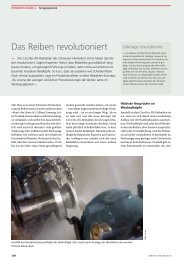
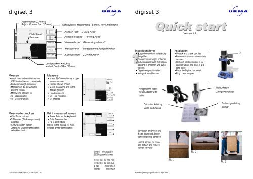
<strong>digiset</strong> 3<br />
Justierbalken Z-Achse<br />
Adjust Control Bar ( Z-axis)<br />
Fadenkreuz<br />
Reticule<br />
Messen<br />
• durch mehrfaches drücken von<br />
ESC in den Messmodus wechseln<br />
• Bildschirm zeigt „Einfahren“<br />
• Messarm in die gewünschte<br />
Position fahren<br />
• Messwerte ablesen 1<br />
• 2 Bezugspunkt<br />
• 3 Messverfahren<br />
Messwerte drucken<br />
• Print Taste drücken<br />
• T-Nummer (Werkzeugnummer)<br />
eingeben<br />
• F2 für Etiketten wählen<br />
Details zur Druckerkonfiguration<br />
siehe Handbuch<br />
V:\Marketing\Kataloge\Digiset3\Quickstart Digiset 3.doc<br />
Justierbalken X-Achse<br />
Adjust Control Bar ( X-axis)<br />
Measure<br />
• press ESC several times to open<br />
measure mode<br />
• Screen shows “insert”<br />
• Move measuring arm to the<br />
desired position<br />
• Read values 1<br />
• 2 Tool reference<br />
• 3 Method<br />
Print measured values<br />
• Press Print on the keyboard<br />
• Enter Tool-Number<br />
• F2 to print labels<br />
Refere to the manual for more<br />
detailed printer configuration<br />
Softkeyleiste/ Hauptmenü Softkey row / mainmenu<br />
„Achsen fest” „Fixed Axes"<br />
„Achsen fliegend“ "Flying Axes"<br />
“Messmethode” “Measuring Method"<br />
“Messbereich” "Measurement Range/Window"<br />
„Konfiguration" „Configuration“<br />
2<br />
3<br />
<strong>Urma</strong> <strong>AG</strong> Werkzeugfabrik<br />
5102 Rupperswil / Schweiz<br />
1<br />
Telefon 0041 62 889 2020<br />
Telefax 0041 62 889 2028<br />
E-Mail: info@urma.ch<br />
Internet: www.urma.ch<br />
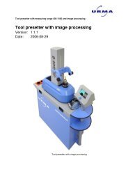
<strong>digiset</strong> 3<br />
Inbetriebnahme<br />
• Auspacken und auf Vollständigkeit<br />
prüfen<br />
• Transportsicherungen entfernen<br />
• Sicherungsschraube für Gegengewicht<br />
� entfernen und aufbewahren<br />
• Digiset waagrecht stellen<br />
• Netzgerät anschliessen<br />
Netzgerät mit Kabel<br />
Power adapter with<br />
cable<br />
Quick start Anleitung<br />
Quick start manual<br />
Schrauben am Deckel und<br />
Boden lösen und Seitenwand<br />
vorsichtig abheben<br />
Unlock screws on cover<br />
and bottom and remove<br />
sidwall carefully<br />
V:\Marketing\Kataloge\Digiset3\Quickstart Digiset 3.doc<br />
Pic. 1<br />
Version 1.2<br />
Installation<br />
• Unpack and check part list<br />
• Remove all transportation safety<br />
devices<br />
• Remove holding screw � for<br />
counter weight and store it at a<br />
safe place<br />
• Place the Digiset horizontal<br />
• Plug power adapter<br />
Pic. 2<br />
Nullpunktdorn<br />
Zero point mandrel<br />
Pic. 3<br />
�<br />
Bedienungsanleitung<br />
Manual
<strong>digiset</strong> 3<br />
Justieren der Optik<br />
• Gerät einschalten<br />
• Taste SETUP � Menü „Beleuchtung“<br />
wählen<br />
• Kontrolle: Die 3 Beleuchtungslinien<br />
� müssen innerhalb des Toleranzfeldes<br />
am oberen Bildrand<br />
liegen.<br />
• Allenfalls Lampen- oder Kameraposition<br />
verändern bis es stimmt.<br />
Ausrichten der Kamera<br />
• Kontrolldorn in die Spindel setzen<br />
• Digiset muss im Messmodus sein<br />
(Gerät einschalten und mit beiden<br />
Achsen über die Referenzpunkte<br />
fahren)<br />
• Kontrolle: Winkel muss 0,00 0 für<br />
Winkel 2 sein<br />
• Ansonsten Kamera verdrehen bis<br />
Winkel stimmt<br />
Sprache auswählen<br />
• Taste SETUP � F3 (Optionen)<br />
� mit Pfeiltasten � bis Sprache<br />
� Pfeiltaste nach links zur<br />
Auswahl der Sprache<br />
• F1 zum bestätigen<br />
V:\Marketing\Kataloge\Digiset3\Quickstart Digiset 3.doc<br />
Adjustment of the optics<br />
• Switch the power on<br />
• Press SETUP key � select menu<br />
„Illumination“<br />
• Check: the 3 lines � have to be<br />
within the tolerance range, shown<br />
at the upper display boarder<br />
• Move lamp or camera if required<br />
to adjust the lines.<br />
Camera adjustment<br />
• Insert master mandrel<br />
• Digiset must be in measuring<br />
mode (switch power on and move<br />
both axes across the zeropoints)<br />
• Check: Angle must be 0,00 0 for<br />
angle 2<br />
• Otherwise turn camera slightly<br />
until angle is correct<br />
Select language<br />
• Press SETUP � F3 (Options) �<br />
use arrow key � to go to<br />
language � left arrow key to<br />
select language<br />
• F1 to confirm<br />
�<br />
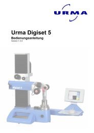
<strong>digiset</strong> 3<br />
Parallelitätskorrektur<br />
Für diese Funktion ist ein Kontrolldorn,<br />
ähnlich <strong>Urma</strong> Bestell-Nr.<br />
221 606 (optional) notwendig<br />
• Messarm zur oberen Position<br />
fahren (Pic 1)<br />
• SETUP drücken � F5 (2x) � F2<br />
(Parall. Korrektur)<br />
• Feld „Aktiv:“ muss auf „ein“<br />
stehen. (Pic 2) Ansonsten mit<br />
Pfeiltasten einstellen<br />
• F2 (Messpunkt neu); Bildschirmanzeige:<br />
„1. Messpkt“ (Pic 3)<br />
• Messen; mit ENTER bestätigen<br />
• Messarm in untere Position<br />
bringen (Pic 4)<br />
• 2. Punkt messen und mit ENTER<br />
bestätigen<br />
• F2 um Vorgang ab zu schliessen<br />
Pic. 2<br />
Nullpunkt speichern<br />
• Nullpunktdorn (im Lieferumfang<br />
enthalten) in Spindel einsetzen<br />
• Messarm auf die korrekte Position<br />
in x- und z-Achse fahren<br />
• SETUP, dann F5 (2x)� F3<br />
(Nullpunkt) drücken<br />
• Werte des Nullpunktdorns über<br />
Tastatur eintragen<br />
• Mit F1 (OK) bestätigen<br />
V:\Marketing\Kataloge\Digiset3\Quickstart Digiset 3.doc<br />
Parallel correction<br />
For this function a master mandrel<br />
similar to <strong>Urma</strong> order-no 221 606<br />
(optional) is needed<br />
• Move the measuring arm to the<br />
upper position (Pic 1)<br />
• Press SETUP on the keyboard;<br />
� F5 (2x) � F2 (Parallel corr.)<br />
• The window “Parallel correction”<br />
must show “yes” for Active. (Pic 2)<br />
use an arrow key to select it<br />
• Press F2 (Measure point)<br />
• the screen shows “1. Point” (Pic<br />
3)<br />
• Measure the first point and<br />
confirm with ENTER<br />
• Move the measuring arm to its<br />
lower position (Pic 5)<br />
• Measure the second point and<br />
confirm with ENTER<br />
• F1 to complete the procedure.<br />
Pic. 3<br />
Store zeropoint<br />
• Put Zeropoint mandrel (included<br />
in delivery) into the spindle<br />
• Move measuring arm to correct<br />
position in x- and z-axes<br />
• Press SETUP � F5(2x) �F3<br />
(Zeropoint)<br />
• Enter values for both axes<br />
according to mandrel<br />
• Press F1 to confirm<br />
Pic. 1<br />
Pic. 4