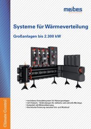
meibes Gross-Heizkreisverteiler und Pumpengruppen bis 2300 kW, Technische Infos

Erfolgreiche ePaper selbst erstellen
Machen Sie aus Ihren PDF Publikationen ein blätterbares Flipbook mit unserer einzigartigen Google optimierten e-Paper Software.
41<br />
6. Pump groups DN25 / DN32<br />
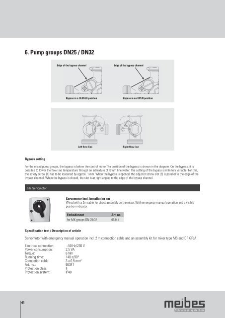
Bypass setting<br />
For the mixed pump groups, the bypass is below the control motor.The position of the bypass is shown in the diagram. On the bypass, it is<br />
possible to lower the fl ow line temperature through an admixture of return line water. The setting of the bypass is infi nitely variable. For this,<br />
the safety screw (1) has to be loosened by approx. 1 mm. When the bypass is opened, the adjuster screw slot (2) is parallel to the edge of the<br />
bypass channel. When the bypass is closed, the slot is at right angles to the edge of the bypass channel.<br />
6.6 Servomotor<br />
Specifi cation text / Description of article<br />
Servomotor with emergency manual operation incl. 2 m connection cable and an assembly kit for mixer type MS and DR GFLA<br />
Electrical connection: ~50 Hz/230 V<br />
Power consumption: 2,5 VA<br />
Torque: 6 Nm<br />
Running time: 140 s/90°<br />
Connection cable: 3 x 0,5 mm 2<br />
Art. no.: 66341<br />
Protection class: II<br />
Protection system: IP40<br />
Edge of the bypass channel Edge of the bypass channel<br />
Bypass in a CLOSED position Bypass in an OPEN position<br />
Left flow line Right flow line<br />
Servomotor incl. installation set<br />
Wired with a 2m cable for direct assembly on the mixer. With emergency manual operation and a visible<br />
position indicator.<br />
Embodiment Art. no.<br />
for MK groups DN 25/32 66341