Si06005 - Schleicher Electronic
Si06005 - Schleicher Electronic
Si06005 - Schleicher Electronic

Sie wollen auch ein ePaper? Erhöhen Sie die Reichweite Ihrer Titel.
YUMPU macht aus Druck-PDFs automatisch weboptimierte ePaper, die Google liebt.
Serviceinformation Nr. SI 06005<br />
Produkt / Typ Artikel-Nr. HW-Stand SW-Version<br />
Promodul-U UBA0,5A R4.314.0040.0 alle<br />
Promodul-U UBA2A R4.314.0070.0 alle<br />
Erweiterung Verbesserung Korrektur Hardware Software Public<br />
Wichtige Anwenderhinweise<br />
Bestimmung/System: Promodul-U<br />
Produktdokumentation: UCN/UCS 50/100 Hardware Art.-Nr. 32214163<br />
English Version : See end of this document<br />
Promodul-U System SPS/CNC Steuerungen<br />
Hier: Hinweise zum Austausch eines UBA0,5A Moduls gegen ein<br />
UBA2A Modul bei bestehenden Anlagen<br />
Das Modul UBA0,5A mit der Bestell Nummer R4.314.0040.0 (Bis 2004: 314 067 97) ist nicht mehr lieferbar.<br />
Das Modul UBA2A mit einer höheren Leistung ist anschlußkompatibel und kann in der Regel als Ersatzteil<br />
an bestehenden Maschinen für das UBA0,5A verwendet werden.<br />
Hier sind die Informationen zusammengefaßt, die beim Austausch an einer bestehenden Anlage wichtig sind.<br />
Fehlermeldung an der Promodul-U Steuereinheit<br />
Die UBA0,5A Karte wird gegen eine UBA2A im ausgeschalteten Zustand ausgetauscht.<br />
Beim Wiedereinschalten der Steuerung in der Schalterstellung RUN zeigt die Steuereinheit den<br />
Steckplatzlistenfehler durch gleichzeitiges Blinken der LED RUN und ERROR und ein Blinken der LED BUS<br />
ACCESS im Gegentakt.<br />
Im Fehlerlogbook der Steuereinheit wird der Fehler 12501/2 (Steckplatzlistenfehler unzulässiges Modul)<br />
eingetragen:<br />
12501/ 2/ x1/ x2 12501 9.07.06 11:12:34 ACT<br />
(Wobei „x1“ Rack und x2 Steckplatz im Rack bedeutet.)<br />
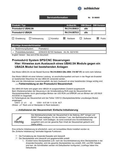
Initialisieren der Steuereinheit: Einfache Initialisierung<br />
Den Betriebsartenschalter der Steuereinheit in die Stellung „INIT“ bringen und<br />
RESET-Taste betätigen. Für die nächsten 7 sec. den Betriebsartenschalter der<br />
Steuereinheit nicht betätigen, da sonst eventuell eine Grundinitialisierung<br />
ausgeführt wird und der gesamte Ram Inhalt der Steuereinheit gelöscht wird<br />
(siehe unten).<br />
Eine einfache Initialisierung ist erforderlich, wenn ein kompatibles Modul installiert worden ist.<br />
Die „Einfache Initialisierung“ beinhaltet folgende Funktionen:<br />
?? Die Formatierung der Anwender-Kassette wird überprüft<br />
?? Die Steckplatzliste wird überprüft und gegebenenfalls erstellt<br />
1. Existiert keine Steckplatzliste (z.B. nach der Grundinitialisierung ohne Steckplatzliste in der<br />
Anwender-Kassette), wird die gesamte Steckplatzliste neu erstellt, DW- und RW-Tabellen<br />
sind leer, die Schnittstellen werden mit Defaultwerten konfiguriert, Lockflags haben ihre<br />
Defaultwerte.
2. Existiert eine Steckplatzliste mit gesetztem Steckplatzlisten-Lockflag, dann bleibt die Liste<br />
unverändert erhalten. Die Hardwarekonfiguration wird lediglich verglichen. In diesem Fall kann<br />
das UB0,5A nur durch eine Änderung der Steckplatzliste durch ein UBA2A ersetzt werden.<br />
Dazu benötigen Sie Unterstützung durch den Maschinenhersteller oder von einem geschulten<br />
Servicetechniker.<br />
3. Existiert eine Steckplatzliste auf der EPROM Kassette oder auf einer schreibgeschützten<br />
RAM Kassette mit auf 0 rückgesetztem Steckplatzlisten-Lockflag, dann wird die folgende<br />
Initialisierung durchgeführt:<br />
?? Ein vorhandenes Paßwort wird gelöscht.<br />
?? Die Hardwarekonfiguration des Systems wird neu eingelesen, d.h. alle Baugruppen<br />
werden in die Steckplatzliste eingetragen. In der Steuerungskonfiguration<br />
(Steckplatzliste) werden die Komponenten: Modultabelle, IX-Tabelle, QX-Tabelle, IW-<br />
Tabelle, QW-Tabelle und Schnittstellenkonfiguration neu erstellt.<br />
?? Die weiteren Komponenten der Steuerungskonfiguration: Lockflags (z.B. für Online-<br />
Compilierung, Objekt im RAM etc.), DW-Tabelle und RW-Tabelle (ab Remotepage<br />
128) bleiben unverändert erhalten.<br />
?? Es gibt danach zwei Steckplatzlisten, eine Vorlage auf der Kassette und die aktuell<br />
gültige Steckplatzliste im RAM.<br />
Falls der Maschinenhersteller eine Steckplatzliste mit gesetztem<br />
Steckplatzlisten -Lockflag projektiert hat (siehe oben 2.) , dann bleibt der<br />
Steckplatzlistenfehler bestehen.<br />
In diesem Falle kontaktieren Sie bitte den Maschinenhersteller.<br />
Ein Ersatz des UBA0,5A Moduls durch ein UBA2A erfordert dann den Eingriff<br />
eines geschulten Servicetechnikers in die Projektierung der Steuereinheit.<br />
Grundinitialisierung der Promodul-U Steuereinheit<br />
Eine Grundinitialisierung ist nur erforderlich, wenn eine neues Betriebssystem oder eine neue Steuereinheit<br />
installiert worden ist. Nach dem Einschalten der Versorgungsspannung bzw. Betätigen der RESET Taste<br />
leuchten für 7 Sekunden die LED´s POWER, RUN und WATCHDOG gleichzeitig.<br />
Innerhalb dieser 7s muß der Betriebsartenschalter in die Position TEST und wieder zurück in die Position INIT<br />
geschaltet werden. Dadurch werden folgende Schritte durchgeführt:<br />
?? Der gesamte RAM-Speicher der UCS/UCN wird gelöscht.<br />
?? Die Formatierung der Anwender-Kassette wird überprüft<br />
?? Steckplatzliste überprüfen und gegebenenfalls erstellen wie bei einfacher Initialisierung<br />
Nach der Grundinitialisierung ist ein weiterer RESET in der TEST Betriebsart notwendig. Damit wird der<br />
gelöschte Speicher reorganisiert.<br />
Da bei einer Grundinitialisierung der gesamte RAM gelöscht wird, sollte<br />
vorher eine Datensicherung vorgenommen werden !
Service information Nr. SI 06005<br />
Product / Typ articel no. HW vers. SW vers.<br />
Promodul-U UBA0,5A R4.314.0040.0 alle<br />
Promodul-U UBA2A R4.314.0070.0 alle<br />
Extension Improvement Correction Hardware Software Public<br />
Important user information<br />
Purpose / system: Promodul-U<br />
Product documentation: Manual UCN/UCS 50/100 Hardware Art.-No. 32214164<br />
Promodul-U system PLC/CNC Controller<br />
Hints for replacement of UBA0,5A module through UBA2A module<br />
at existing systems<br />
The module UBA0,5A article no R4.314.0040.0 (until 2004: 314 067 97) is no more available.<br />
The module UBA2A with higher output performance is compatible in I/O connectors. It can be used as a spare<br />
part at existing machines to replace a defect UBA0,5A module.<br />
Here are all information to replace the module.<br />
Errormessage at the Promodul-U Control unit<br />
The UBA0,5A module will be replaced through a UBA2A during Power off of the system.<br />
After restart the system with operation mode switch in position RUN the control unit shows a so called slot<br />
list error synchronous blinking of LED RUN and ERROR and a counterwise blinking of LED BUS ACCESS .<br />
At the error logbook of the control unit appears error 12501/2 :<br />
12501/ 2/ x1/ x2 12501 9.07.06 11:12:34 ACT<br />
( „x1“ is rack position and x2 is slot position.)<br />
Initialization of control unit: simple initialization<br />
Set operation mode switch in position INIT and press RESET key. Wait about 7<br />
seconds and don’t touch anything !<br />
In case you switch during 7 seconds the operation mode switch you maybe<br />
cause a default initialization with a proper RAM clear!<br />
A simple initialization ist necessary after the replace of a compatible module.<br />
The simple initialization contains following functions:<br />
?? The formatting of the user cassette will be checked<br />
?? The module location list (slot list) will be checked and if necessary created
1. If there is no module location list (slot list) the whole module location list is created, DW and RW<br />
tables are empty, the interfaces are configured with default values and lock flags have their<br />
default values.<br />
2. If there is a module location list with a defined module location list lock flag the list will be kept<br />
as it is. Only the hardware configuration will be compared. In this case the replacement of the<br />
UBA0,5A through a UBA2A is not in a simple way possible. It is necessary to change the slot<br />
list. The change of the slot list can be realized by the machine manufacturer or by trained service<br />
personal.<br />
3. If there is a module location list with a module location list lock flag reset to 0 on the EPROM<br />
cassette or on a write-protected RAM cassette, the following initialization will be carried out:<br />
?? Any existing password will be deleted.<br />
?? The hardware configuration of the system is read again, i.e. all the components are entered in<br />
the module location list. In the control configuration (module location list) a new module table,<br />
IX table, QX table, IW table, QW table and the interface configuration components are<br />
created.<br />
?? Other components of the control configuration: Lock flags (e.g. for online compiling, object in<br />
RAM etc.), DW table and RW table (from remotepage 128) are kept as they are.<br />
?? There are now two module location lists, a template on the user cassette and the current<br />
module location list in the RAM.<br />
If the machine manufacturer has projected a slot list in the control unit with a list<br />
lock flag = 1 than (see top point 2.) , then the slot list error could not be deleted.<br />
In this case please contact the machine manufacturer.<br />
The replace of the UBA0,5A module through a UBA2A module efforts the<br />
maintenance of trained service personal at the control unit.<br />
Default initialization of Promodul-U control unit<br />
A default initialization is only necessary if a new operating system or a new control unit has been installed.<br />
When the power supply has been switched on or the RESET key has been pressed the POWER, RUN and<br />
WATCHDOG LEDs are all ON for 7 seconds.<br />
Within these 7 seconds the operating mode switch must be moved to TEST and back again to INIT. This will<br />
result in the following steps being carried out:<br />
?? The whole RAM memory of the UCS/UCN will be cleared.<br />
?? The formatting of the user cassette will be checked<br />
?? The module location list will be checked and if necessary created (as in simple initialization)<br />
?? After basic initialization another RESET must be carried out in TEST mode. This is to reorganize<br />
the deleted memory.<br />
The entire RAM will be deleted during a default initialization. Back up all<br />
your data before running a default initialization.<br />
HE <strong>Si06005</strong>.doc 10.07.2006 Seite 4 / 4