VKR 16-4_32-8 NEU.ind - Videor
VKR 16-4_32-8 NEU.ind - Videor
VKR 16-4_32-8 NEU.ind - Videor

Sie wollen auch ein ePaper? Erhöhen Sie die Reichweite Ihrer Titel.
YUMPU macht aus Druck-PDFs automatisch weboptimierte ePaper, die Google liebt.
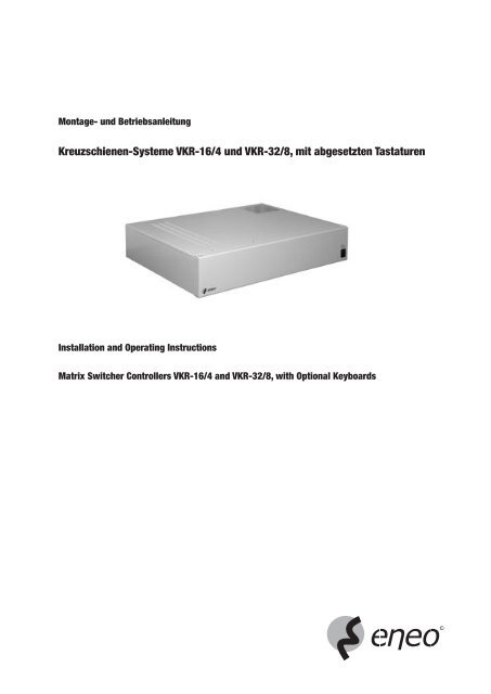
Montage- und Betriebsanleitung<br />
Kreuzschienen-Systeme <strong>VKR</strong>-<strong>16</strong>/4 und <strong>VKR</strong>-<strong>32</strong>/8, mit abgesetzten Tastaturen<br />
Installation and Operating Instructions<br />
Matrix Switcher Controllers <strong>VKR</strong>-<strong>16</strong>/4 and <strong>VKR</strong>-<strong>32</strong>/8, with Optional Keyboards<br />
1
Inhalt<br />
1. Allgemeine Beschreibung....................................................................3<br />
2. Sicherheitshinweise / Pflege ...............................................................4<br />
3. Mitgeliefertes Zubehör ........................................................................4<br />
4. Installation des Kreuzschienen-Systems .............................................5<br />
4.1 Frontseite ...........................................................................................5<br />
4.2 Rückseite............................................................................................5<br />
5. Anschluss-Schema .............................................................................7<br />
6. Interne Konfiguration...........................................................................8<br />
7. Steckerbelegung.................................................................................9<br />
7.1 Sub-D-Stecker, 25-pol. .......................................................................9<br />
7.2 D-9F-Stecker, 9-pol. .........................................................................11<br />
7.3 Anschluss eines Bediengerätes.........................................................11<br />
8. Programmierung über Bildschirmmenü.............................................12<br />
8.1 Systemprogrammierung ...................................................................12<br />
8.2 Alarmprogrammierung......................................................................17<br />
8.3 Monitorprogrammierung ...................................................................18<br />
8.4 Kameraprogrammierung...................................................................19<br />
8.5 Programmierung der Peripherie ........................................................20<br />
8.6 Programmierung der Sequenzeinstellungen ......................................22<br />
8.7 Auswahl der Menüsprache................................................................24<br />
8.8 Sichern der Einstellungen .................................................................24<br />
9. Fehlersuche und Fehlerbehebung .....................................................25<br />
10. Spezifikationen und Zubehör.............................................................26<br />
11. Maßzeichnungen ..............................................................................27<br />
Anhang......................................................................................................28<br />
Betriebsanleitung<br />
Installation and Operating Instructions<br />
⇒<br />
www.eneo-security.com/manuals<br />
2<br />
Contents<br />
1. General Description ..........................................................................33<br />
2. Safety Instructions/Maintenance .......................................................34<br />
3. Accessories Supplied........................................................................34<br />
4. Installation of the Matrix Switcher Controller .....................................35<br />
4.1 Front.................................................................................................35<br />
4.2 Rear..................................................................................................35<br />
5. Connection Diagram ........................................................................37<br />
6. Setting the Jumpers..........................................................................38<br />
7. Pin Assignment.................................................................................39<br />
7.1 Sub-D Connections, 25 pin ...............................................................39<br />
7.2 D-9F Plug, 9 pin................................................................................41<br />
7.3 Connection of an Operating Unit........................................................41<br />
8. Programming via On-Screen Menu ...................................................42<br />
8.1 System Programming .......................................................................42<br />
8.2 Alarm Programming..........................................................................47<br />
8.3 Monitor Programming .......................................................................48<br />
8.4 Camera Programming.......................................................................49<br />
8.5 Programming of Equipments.............................................................50<br />
8.6 Programming of Sequence Settings ..................................................52<br />
8.7 Selection of Menu Language.............................................................54<br />
8.8 Securing the Settings........................................................................54<br />
9. Trouble Shooting...............................................................................55<br />
10. Specifications and Accessories .........................................................56<br />
11. Dimensional Drawings ......................................................................57<br />
Appendix ...................................................................................................58
1. Allgemeine Beschreibung<br />
• Das <strong>VKR</strong>-Kreuzschienensystem ist eine mikroprozessorgesteuerte Video- und Steuerkreuzschiene.<br />
• Mit der <strong>VKR</strong>-<strong>16</strong>/4 können bis zu <strong>16</strong> Kameras auf bis zu 4 Monitore geschaltet werden.<br />
• Mit der <strong>VKR</strong>-<strong>32</strong>/8 können bis zu <strong>32</strong> Kameras auf bis zu 8 Monitore geschaltet werden.<br />
• Als Steuerprotokoll können den Eingängen folgende Protokolle zugewiesen werden: RS-485 (VT), RS-422, (Pelco D, seriell und koaxial).<br />
Hinweis:<br />
Die Betriebsanleitung in englischer und deutscher Sprache f<strong>ind</strong>en Sie unter „www.eneo-security.com/Manuals” im Internet.<br />
Beschreibung der Funktionen <strong>VKR</strong>-<strong>16</strong>/4 <strong>VKR</strong>-<strong>32</strong>/8<br />
Integrierte menügeführte Über den ersten Monitor-Ausgang s<strong>ind</strong> die On-Screen-Menüs für die Systemprogrammierung verfügbar.<br />
Einstellungen<br />
Passwortschutz mit Benutzer-Login 8 dem Benutzer zuweisbare Passwörter stehen zur Verfügung, um den Benutzer-Zugriff auf das System zu<br />
beschränken. Jeder Benutzer muss sich mit Name und Passwort im System anmelden.<br />
Die Anmelde-Option kann deaktiviert werden.<br />
Prioritätsebenen-Vergabe 8 verschiedenen Benutzern zuordenbare Prioritätsebenen erlauben die Anwendung von Einstellungen von<br />
Benutzern mit hoher Priorität und die Sperrung von Benutzern mit niedriger Priorität.<br />
Programmierbare Benutzerdefinierte, auf dem Bildschirm eingeblendete Pseudokamera-Nummern, die Stockwerken, Zonen, Kameranummerierung<br />
Bereichen usw. zugeordnet s<strong>ind</strong>, ist es möglich, Hardware-definierte Nummern zu ersetzen, um die<br />
Identifizierung der Position zu erleichtern.<br />
System Partitionierung Mit programmierbaren Partitionen ist es möglich, den Benutzerzugriff auf Monitore, Kameras, Kamerasteuerung<br />
und den Monitorzugriff auf bestimmte Kameras zu limitieren.<br />
Touren/Salvos Bis zu <strong>32</strong> universelle Touren können definiert werden. Jeder Ablauf kann aus bis zu 64 Schritten bestehen.<br />
Weiterschaltung zum nächsten Schritt erfolgt, wenn eine der ausgewählten Bedingungen eintritt. Die Bedingungen<br />
s<strong>ind</strong> Verweilzeit, Digitaleingänge, Zustand der Alarmeingänge, Zeitfensterstatus und Funktionsstatus.<br />
Die Verweilzeit kann von 0 bis 999 Sek. eingestellt werden. Jeder Schritt kann eine der folgenden Funktionen<br />
ausführen: Kamera auf Monitor-Schaltungen mit zusätzlichen Funktionen einschl. Voreinstellungen, Start einer<br />
Monitorsequenz, Start einer Multimonitorsequenz, Salven auf Monitor-Schaltungen, Relais- und Schaltkontakt-<br />
aktivierung.<br />
Monitor-Sequenz <strong>32</strong> Sequenzen von bis zu <strong>32</strong> Kameras mit unterschiedlicher Verweilzeit für jede Kamera s<strong>ind</strong> benutzerdefinierbar.<br />
Multi-Monitor-Sequenzen Die Multisequenz-Schaltung definiert die Sequenzen für die ausgewählten Monitore. Bis zu <strong>32</strong> Multisequenzen<br />
können definiert werden.<br />
Gruppenschaltung <strong>32</strong> Gruppen können für einen Direktaufruf des Bedieners auf einen Monitor definiert werden. Für jede Kamera in<br />
jeder Gruppe kann eine Szenenvoreinstellung und eine externe Funktion definiert werden.<br />
Videosignal-Ausfall-Überwachung Das Videosignal wird für jeden Kameraeingang überwacht. Wenn ein Fehler auftritt, steht eine entsprechende<br />
Alarmaufschaltung zur Verfügung.<br />
Automatische Aktivierung Das <strong>VKR</strong>-Kreuzschienensystem wird automatisch in Abhängigkeit vom Alarmstatus, Zeitfenster und digitalen<br />
Eingängen aktiviert.<br />
Alarmverarbeitung Diese Funktion betrifft die Möglichkeiten der Diese Funktion betrifft die Möglichkeiten der<br />
<strong>16</strong> Alarmeingänge. Jeder Alarmeingang kann im Setup- <strong>32</strong> Alarmeingänge. Jeder Alarmeingang kann im Setup-<br />
Menü aktiviert und deaktiviert werden. Die Alarmein- Menü aktiviert und deaktiviert werden. Die Alarmein-<br />
gänge können durch Kontaktschließung oder -öffnung gänge können durch Kontaktschließung oder -öffnung<br />
aktiviert werden. Der Alarmeingang kann auch als aktiviert werden. Der Alarmeingang kann auch als<br />
Fernsteueralarm-Eingang definiert werden. In diesem Fernsteueralarm-Eingang definiert werden. In diesem<br />
Fall kann der Alarm von einem Computer, einer Alarm- Fall kann der Alarm von einem Computer, einer Alarm-<br />
zentrale usw. ausgelöst werden. Die Rücksetzung des zentrale usw. ausgelöst werden. Die Rücksetzung des<br />
Alarms kann manuell oder automatisch, sofort oder Alarms kann manuell oder automatisch, sofort oder<br />
nach einer voreingestellten Verzögerungszeit erfolgen. nach einer voreingestellten Verzögerungszeit erfolgen.<br />
Echtzeituhr Die Echtzeituhr mit der Zeitfensterfunktion und integriertem Kalender verfügt über alle Möglichkeiten, das<br />
Kreuzschienensystem abhängig von Zeit und Datum zu steuern. Die Kalenderfunktion ermöglicht es, jeden Tag im<br />
Jahr bis zu 4 unterschiedliche Zeitfenster zuzuordnen. Bis zu <strong>16</strong> Zeitfenster können definiert werden, von denen<br />
jedes 4 Zeitintervalle und den Tagestyp beinhaltet.<br />
Funktionsbearbeitung Eine Funktion ist die logische Summe aus Alarmstatus, Zeitfensterstatus, Funktionsstatus und digitalen Eingängen.<br />
Funktionen werden benutzt, um bis zu 3 Bedingungen (Alarmstatus, Zeitfenster usw.) in einem Funktionsstatus zu<br />
kombinieren, der einen Vorgang auslöst. Die Verknüpfungen zwischen den Bedingungen können ein logisches<br />
AND, OR, NOR, NAND und die Negierung der gesamten Funktionen sein. Bis zu <strong>32</strong> Funktionen können definiert<br />
werden.<br />
Auslösen eines Vorganges Bis zu <strong>32</strong> Vorgänge können definiert werden. Die Vorgangsausführung ist die Programmiermöglichkeit, um die<br />
Bearbeitung von Alarmen, Zeitfenstern, Digitaleingängen, Funktionen usw. zu automatisieren. Die ausgewählte<br />
Ausführung wird automatisch gestartet, wenn der ausgewählte Vorgang eintritt. Der Vorgang kann aus einer<br />
Kameraaufschaltung auf einen Monitor mit zusätzlichen Funktionen einschl. Voreinstellungen, Start einer Monitor-<br />
sequenz, Start einer Multi-Monitorsequenz, Start einer Gruppe auf Monitoren, Start einer Tour, Relaisschaltungen<br />
und <strong>Videor</strong>ekorder-Steuerungen bestehen.<br />
3
Alarmstatus-Ausgang Ein- oder mehrere Relaisausgänge oder Schaltausgänge (offener Kollektor) können zur Aktivierung freigegeben<br />
werden, wenn ein Alarm auftritt.<br />
Mehrsprachige Bildschirmanzeige Das Datum, die Zeit, Kameranummer, Kamera- und Monitor (Alarm)status und ein programmierbarer Titel mit <strong>16</strong><br />
Zeichen können auf einem oder mehreren Monitoren mit dieser Option dargestellt werden. Die Position des<br />
Fensters kann definiert werden. Die Einblendung der Kameranummer, des Titels in Alarm- und Normalmodus und<br />
die Datums-/Zeiteinblendung können vom Benutzer aktiviert bzw. deaktiviert werden.<br />
RS-2<strong>32</strong>/RS-485 Schnittstellen Bis zu 4 Schnittstellen stehen zur Verfügung, um Bis zu 4 Schnittstellen stehen zur Verfügung, um<br />
für Systemkommunikation maximal 4 Bediengeräte und andere Geräte mit serieller maximal 8 Bediengeräte und andere Geräte mit serieller<br />
Steuerschnittstelle wie Telemetrieempfänger, Video- und Koax-Steuerschnittstelle wie Telemetrieempfänger,<br />
rekorder, PC’s usw. anzuschließen. Viedorekorder, PC’s usw. anzuschließen.<br />
Standortsteuerung Die RS-485/RS-2<strong>32</strong>-Schnittstellen dienen der Steuerung von Empfängern, um feste oder variable Schwenk- und<br />
Neigebewegungen, Zoomobjektiv, Focus- und Blendeneinstellungen und Zusatzeinrichtungen an entsprechend<br />
ausgerüsteten Kamerastandorten zu steuern. Pro Kamera können bis zu 255 Festpositionen (Presets) programmiert<br />
werden.<br />
<strong>Videor</strong>ekorder-Steuerung <strong>Videor</strong>ekorder-Steuerung über die Kreuzschiene. Die Sequenz des definierten Monitors ist von der <strong>Videor</strong>ekorder-<br />
Steuerung abhängig.<br />
<strong>Videor</strong>ekorder-Fernbedienung Die Steuerung eines <strong>Videor</strong>ekorders kann über die serielle RS-2<strong>32</strong>- und/oder der analogen Schnittstelle erfolgen.<br />
2. Sicherheitshinweise/Pflege<br />
• Bevor Sie das Gerät anschließen und in Betrieb nehmen, lesen Sie bitte zuerst die Sicherheitshinweise und die Betriebsanleitung.<br />
• Bewahren Sie die Betriebsanleitung für spätere Verwendung sorgfältig auf.<br />
• Die Lüftungsschlitze des Gerätes niemals abdecken.<br />
• Das Gerät ist nur für den Betrieb in geschlossenen Räumen vorgesehen und ist gegen E<strong>ind</strong>ringen von Wasser und Feuchtigkeit schützen.<br />
• Sollte dennoch Feuchtigkeit eingedrungen sein, das Gerät nie unter diesen Bedingungen einschalten. Zur Überprüfung an eine qualifizierte Servicestelle<br />
geben.<br />
• Das Gehäuse darf nur durch dafür autorisierte Personen geöffnet werden. Instandsetzung nur durch qualifiziertes Servicepersonal.<br />
• Vor dem Öffnen des Gerätes ist eine Netztrennung erforderlich.<br />
• Das Gerät nur in einem Temperaturbereich von 0 bis +50°C und einer Luftfeuchtigkeit bis max. 90% betreiben.<br />
• Niemals metallische oder andere Gegenstände durch die Lüftungsschlitze stecken, dies könnte das Gerät dauerhaft schädigen.<br />
• Das Gerät ist vor großer Hitze, Staub, Feuchtigkeit und Vibrationseinwirkung zu schützen.<br />
• Die Belastung des Gehäuses durch schwere Gegenstände ist zu vermeiden.<br />
• Achten Sie beim Verlegen des Anschlusskabels unbedingt darauf, dass es nicht belastet, geknickt oder beschädigt wird und keine Feuchtigkeit e<strong>ind</strong>ringen<br />
kann.<br />
• Nur Original-Ersatzteile der Fa. <strong>Videor</strong> Technical verwenden.<br />
• Zur Reinigung des Gerätegehäuses nur ein mildes Haushaltsmittel verwenden. Niemals Verdünner oder Benzin benutzen. Dies kann die Oberfläche<br />
dauerhaft schädigen.<br />
WARNUNG:<br />
Dies ist eine Einrichtung der Klasse A. Diese Einrichtung kann im Wohnbereich Funkstörungen verursachen; in diesem Fall kann vom Betreiber<br />
verlangt werden, angemessene Maßnahmen durchzuführen und dafür aufzukommen.<br />
3. Mitgeliefertes Zubehör<br />
• Betriebsanleitung<br />
• Netzanschlusskabel<br />
• Anschluss-Kit für den Anschluss abgesetzter Bediengeräte<br />
• 19”-Winkel (L-Winkel), 4 Schrauben<br />
• 3 1/2” Diskette, die die Möglichkeit, die Menüprogrammierung zu sichern (Trans-Matrix), und ein Software-Update (BIN-Datei) beinhaltet<br />
4
4. Installation des Kreuzschienen-Systems<br />
4.1 Frontseite<br />
L LED-Anzeige Bei eingeschaltetem Gerät leuchte die LED Anzeige<br />
P Netzschalter Ein-/ Ausschalter<br />
4.2 Rückseite<br />
<strong>VKR</strong>-<strong>16</strong>/4<br />
AC IN<br />
Hinweis Rutschfeste Gummifüße am Gehäuseboden ermöglichen die Nutzung als Tischgerät<br />
Hinweis Die Kreuzschiene kann in einen Standard-19”-Schrank eingebaut werden.<br />
LED<br />
O.C. OUT ALARM IN<br />
VCR 1<br />
ANALOG<br />
1 Netz-Ein Netzstecker<br />
VCR 2<br />
ANALOG<br />
2 LED Anschluss für eine Leuchtdiodenanzeige und für Digitaleingänge (D-25F). 2 LED-Anzeigen mit gemeinsamer Anode können<br />
mit diesem Anschluss verbunden werden. Weiterhin stehen 7 universelle Digitaleingänge zur Verfügung.<br />
3 O.C.OUT 25-pol. Sub-D-Stecker für 24 Schaltausgänge (Offener Kollektor).<br />
RS-485<br />
KBD<br />
4 ALARM IN 25-pol. Sub-D-Stecker für <strong>16</strong> Alarmeingänge und 2 Relaisausgängen mit Umschalt-Kontakten.<br />
5 VCR 1 9-pol. Sub-D-Stecker zur Steuerung eines analoggesteuerten <strong>Videor</strong>ekorders.<br />
ANALOG<br />
6 VCR 2 9-pol. Sub-D-Stecker zur Steuerung eines analoggesteuerten <strong>Videor</strong>ekorders.<br />
ANALOG<br />
7 RS-485 / KBD RS-485-Stecker (9-pol. Sub-D-Stecker) zum Anschluss von bis zu 4 Bediengeräten. Mit der grün leuchtenden LED wird der<br />
RX-Status, mit der rot leuchtenden LED wird der TX-Status angezeigt.<br />
8 RS-485 / P&T Es können bis zu <strong>16</strong> Peripherie-Geräte (z. B. S/N-Köpfe) angeschlossen werden. Mit der grün leuchtenden LED wird der<br />
RX-Status, mit der rot leuchtenden LED wird der TX-Status angezeigt.<br />
9 RS-2<strong>32</strong> / VCR Anschluss eines <strong>Videor</strong>ekorders mit RS-2<strong>32</strong>- und RS-485-Schnittstelle (D-9F). Es kann jeweils ein <strong>Videor</strong>ekorder an einer<br />
Schnittstelle angeschlossen werden. Mit der grün leuchtenden LED wird der RX-Status, mit der rot leuchtenden LED wird der<br />
TX-Status angezeigt.<br />
10 RS-2<strong>32</strong> / PC RS-2<strong>32</strong>-Anschluss zum Anschluss eines PC‘s. Mit der grün leuchtenden LED wird der RX-Status, mit der rot leuchtenden LED<br />
wird der TX-Status angezeigt.<br />
11 VCR-CLK Zwei BNC-Stecker zum Anschluss der Triggerimpulse für 2 <strong>Videor</strong>ekorder.<br />
RS-485<br />
P&T<br />
12 SYNC IN BNC-Stecker für den Sync-Eingang (z.B. Taktgenerator)<br />
13 VIDEO IN BNC-Stecker für <strong>16</strong> Video-Eingänge (z.B. Kameras)<br />
14 VIDEO OUT BNC-Stecker für 4 Videoausgänge (z.B. Monitore)<br />
15 SYNC OUT BNC-Stecker für <strong>16</strong> Synchron-Ausgänge<br />
RS-2<strong>32</strong><br />
VCR<br />
RS-2<strong>32</strong><br />
PC<br />
Ser.No.<br />
5<br />
1<br />
2<br />
VCR CLK 1 VIDEO IN<br />
13 VIDEO OUT 1 SYNC OUT<br />
13<br />
SYNC IN<br />
4<br />
8<br />
12<br />
<strong>16</strong> 4<br />
4<br />
P<br />
8 12 <strong>16</strong><br />
L
<strong>VKR</strong>-<strong>32</strong>/8<br />
AC IN<br />
LED O.C. OUT ALARM<br />
IN / OUT<br />
1 Netzeingang Eingang<br />
ALARM IN<br />
VCR 1<br />
VCR 2<br />
ANALOG<br />
2 LED Anschluss für eine Leuchtdiodenanzeige und für Digitaleingänge (D-25F). 2 LED-Anzeigen mit gemeinsamer Anode können<br />
mit diesem Anschluss verbunden werden. Weiterhin stehen 7 universelle Digitaleingänge zur Verfügung.<br />
3 O.C.OUT 25-pol. Sub-D-Stecker für 24 Schaltausgänge (Offener Kollektor)<br />
4 ALARM IN / OUT 25-pol. Sub-D-Stecker für <strong>16</strong> Alarmeingänge und 2 eingebauten Relais mit Umschalt-Kontakten.<br />
5 ALARM IN 25-pol. Sub-D-Stecker für 8 Alarmeingänge und 8 freien Eingängen<br />
RS-485<br />
KBD<br />
RS-2<strong>32</strong><br />
VCR<br />
RS-485<br />
P&T RS-2<strong>32</strong><br />
VCR<br />
6 VCR 1 / VCR 2 / 9-pol. Sub-D-Stecker zur Steuerung von 2 analoggesteuerten <strong>Videor</strong>ekordern (Steuerung auf Anfrage)<br />
ANALOG<br />
7 RS-485 / KBD RS-485-Stecker (9 pol. Sub-D-Stecker) zum Anschluss von bis zu 8 Bediengeräten. Mit der grün leuchtenden LED wird der<br />
RX-Status, mit der rot leuchtenden LED wird der TX-Status angezeigt.<br />
8 RS-2<strong>32</strong> / VCR Anschluss von <strong>Videor</strong>ekordern mit RS-2<strong>32</strong>- und RS-485Schnittstelle (D-9F). Mit der grün leuchtenden LED wird der RX-Status,<br />
mit der rot leuchtenden LED wird der TX-Status angezeigt.<br />
8 RS-485 / P&T Es können bis zu <strong>32</strong> Peripherie-Geräte (z.B. S/N-Köpfe) angeschlossen werden. Mit der grün leuchtenden LED wird der<br />
RX-Status, mit der rot leuchtenden LED wird der TX-Status angezeigt.<br />
9 RS-2<strong>32</strong> / PC RS-2<strong>32</strong>-Anschluss für einen PC (Zur Steuerung die beiliegende Software verwenden). Mit der grün leuchtenden LED wird der<br />
RX-Status, mit der rot leuchtenden LED wird der TX-Status angezeigt.<br />
10 VCR-CLK Zwei BNC-Stecker zum Anschluss der Triggerimpulse für 2 <strong>Videor</strong>ekorder<br />
11 SYNC IN BNC-Stecker für den Sync-Eingang (z.B. Taktgenerator)<br />
12 VIDEO IN BNC-Stecker für <strong>32</strong> Video-Eingänge (z.B. Kameras)<br />
13 VIDEO OUT BNC-Stecker für 8 Videoausgänge (z.B. Monitore)<br />
Ser.No.<br />
1<br />
2<br />
VCR CLK 1 5 9 VIDEO IN<br />
21 25 29 VIDEO OUT<br />
SYNC IN<br />
6<br />
4<br />
8<br />
12<br />
<strong>16</strong><br />
20 24 28 <strong>32</strong> 4 8
5. Anschluss-Schema<br />
• Stellen Sie sicher, dass die Stromversorgung ausgeschaltet ist bevor andere Geräte angeschlossen werden.<br />
• Hinweise zum Anschluss externer Geräte f<strong>ind</strong>en Sie in der jeweiligen Betriebsanleitung.<br />
Hinweis:<br />
• Diese Verb<strong>ind</strong>ungen s<strong>ind</strong> typisch für das Standard- oder Systembediengerät.<br />
• Der RS-485/KBD-Anschluss erlaubt den Anschluss von 8 Bediengeräten.(<strong>VKR</strong>-KB1 und/oder <strong>VKR</strong>-KB2).<br />
• Der RS-485/P&T-Anschluss erlaubt den seriellen Steuer-Anschluss von bis zu <strong>16</strong> (<strong>32</strong>) Spectra Dome-Kameras, Esprit-Serie (Pelco) oder<br />
VPT-41/42 - S/N-Köpfen und <strong>VKR</strong>-PTZFI Telemetrieempfängern.<br />
• Der RS-2<strong>32</strong>/VCR-Anschluss und der RS-2<strong>32</strong>/PC-Anschluss ermöglicht den Anschluss von bis zu 2 <strong>Videor</strong>ekordern, Telemetrieempfängern<br />
oder PC‘s.<br />
• Koaxialsteuerung<br />
<strong>VKR</strong>-<strong>16</strong>/4<br />
<strong>VKR</strong>-<strong>32</strong>/8<br />
AC IN<br />
AC IN<br />
LED<br />
ALARM<br />
KONTAKTE<br />
O.C. OUT ALARM IN<br />
VCR 1<br />
ANALOG<br />
ALARM<br />
KONTAKTE<br />
LED O.C. OUT ALARM<br />
IN / OUT<br />
ALARM IN<br />
VCR 2<br />
ANALOG<br />
VCR 1<br />
VCR 2<br />
ANALOG<br />
RS-485<br />
KBD<br />
RS-485<br />
KBD<br />
RS-485<br />
P&T<br />
VCR<br />
VCR<br />
RS-2<strong>32</strong><br />
VCR<br />
VCR<br />
VCR<br />
RS-2<strong>32</strong><br />
VCR<br />
RS-485<br />
P&T RS-2<strong>32</strong><br />
VCR<br />
Ser.No.<br />
PC<br />
RS-2<strong>32</strong><br />
PC<br />
Ser.No.<br />
PC<br />
1<br />
2<br />
7<br />
1<br />
2<br />
SYNC IN<br />
VCR CLK 1 VIDEO IN<br />
13 VIDEO OUT 1 SYNC OUT<br />
13<br />
SYNC IN<br />
4<br />
KAM<br />
8<br />
12<br />
KAM<br />
<strong>16</strong> 4<br />
MON<br />
4<br />
8 12 <strong>16</strong><br />
VCR CLK 1 5 9 VIDEO IN<br />
21 25 29 VIDEO OUT<br />
4<br />
8<br />
KAM<br />
12<br />
<strong>16</strong><br />
KAM<br />
20 24 28 <strong>32</strong> 4 8<br />
MON
6. Interne Konfiguration<br />
Setzen der Steckbrücken<br />
<strong>VKR</strong>-<strong>16</strong>/4<br />
werkseitige Einstellung<br />
NORMAL<br />
J110<br />
1<br />
SET<br />
DEFAULT<br />
RS-485 KBD<br />
Abschluss<br />
(120 Ohm)<br />
<strong>VKR</strong>-<strong>32</strong>/8<br />
werkseitige Einstellung<br />
OP CL<br />
1<br />
J302<br />
Betriebs<br />
Modus<br />
J110<br />
J201<br />
OP OP<br />
1 CL 1<br />
CL<br />
J202<br />
RS-485 P&T<br />
Abschluss<br />
(120 Ohm)<br />
Auf Werkeinstellung zurücksetzen:<br />
1. Kreuzschiene vom Netz trennen.<br />
OP-Offener Eingang<br />
CL-75 Ohm-Abschluss<br />
2. J110 (<strong>VKR</strong>-<strong>16</strong>/4) bzw. J105 (<strong>VKR</strong>-<strong>32</strong>/8) auf SET DEFAULT setzen.<br />
3. Kreuzschiene ans Netz anschließen.<br />
SYNC IN<br />
Abschluss<br />
(75 Ohm)<br />
VIDEO IN 1-<strong>16</strong> Abschlusswiderstände (75 Ohm)<br />
RS-485 P&T<br />
Abschluss<br />
(120 Ohm)<br />
NORMAL<br />
1<br />
J105<br />
SET<br />
DEFAULT<br />
1 J301<br />
CL<br />
OP-Offener Eingang<br />
CL-75 Ohm-Abschluss<br />
Betriebs<br />
Modus<br />
J106<br />
KP101<br />
4. J110 (<strong>VKR</strong>-<strong>16</strong>/4) bzw. J105 (<strong>VKR</strong>-<strong>32</strong>/8) auf NORMAL setzen.<br />
OP<br />
RS-485 KBD<br />
Abschluss<br />
(120 Ohm)<br />
KP101<br />
OP-Offener Eingang<br />
CL-75 Ohm-Abschluss<br />
Reset Taster<br />
KP101<br />
OPEN J401<br />
SYNC IN<br />
Abschluss<br />
(75 Ohm)<br />
VIDEO IN 1-<strong>32</strong> Abschlusswiderstände (75 ohm)<br />
75Ohm<br />
1<br />
Reset Taster<br />
KP101<br />
OPEN<br />
J433<br />
75Ohm<br />
8<br />
• Bei Software-Fehlfunktion den Reset Taster (KP101) betätigen<br />
• Brücken 201 für RS-485 + P&T Port aktiv oder nicht aktiv<br />
• Brücken 401 für Synchronisations-Eingang aktiv oder nicht aktiv<br />
• Brücken 601-6<strong>16</strong> 75 Ohm-Abschluss EIN oder AUS<br />
• Bei Software-Fehlfunktion den Reset Taster (KP101) betätigen<br />
• Brücken 301 für RS-485 + P&T Port aktiv oder nicht aktiv<br />
• Brücken 433 für Synchronisations-Eingang aktiv oder nicht aktiv<br />
• Brücken 401-4<strong>32</strong> 75 Ohm-Abschluss EIN oder AUS
7. Steckerbelegung<br />
7.1 Sub-D-Anschlüsse, 25-pol.<br />
<strong>VKR</strong>-<strong>16</strong>/4<br />
9<br />
LED O.C. ALARM<br />
PIN Ausgang Eingang<br />
1 LED Disp. a Ausgang 1 Alarm Eingang 1<br />
2 LED Disp. b Ausgang 2 Alarm Eingang 2<br />
3 LED Disp. c Ausgang 3 Alarm Eingang 3<br />
4 LED Disp. d Ausgang 4 Alarm Eingang 4<br />
5 LED Disp. e Ausgang 5 Alarm Eingang 5<br />
6 LED Disp. f Ausgang 6 Alarm Eingang 6<br />
7 LED Disp. g Ausgang 7 Alarm Eingang 7<br />
8 LED Disp. DP Ausgang 8 Alarm Eingang 8<br />
9 LED 1 Com.A Ausgang 9 Alarm Eingang 9<br />
10 LED 2 Com.A Ausgang 10 Alarm Eingang 10<br />
11 Masse Ausgang 11 Alarm Eingang 11<br />
12 Masse Ausgang 12 Alarm Eingang 12<br />
13 Masse Ausgang 13 Alarm Eingang 13<br />
14 Dig.Eingang 1 Ausgang 14 Alarm Eingang 14<br />
15 Dig.Eingang 2 Ausgang 15 Alarm Eingang 15<br />
<strong>16</strong> Dig.Eingang 3 Ausgang <strong>16</strong> Alarm Eingang <strong>16</strong><br />
17 Dig.Eingang 4 Ausgang 17 Masse<br />
18 Dig.Eingang 5 Ausgang 18 Masse<br />
19 Dig.Eingang 6 Ausgang 19 Masse<br />
20 Dig.Eingang 7 Ausgang 20 Relais 1 Gemeinsam<br />
21 +5 V Ausgang 21 Relais 1 Öffner (NC)<br />
22 +5 V Ausgang 22 Relais 1 Schließer (NO)<br />
23 +5 V Ausgang 23 Relais 2 Gemeinsam<br />
24 Masse Ausgang 24 Relais 2 Öffner (NC)<br />
25 Masse Masse Relais 2 Schließer (NO)
<strong>VKR</strong>-<strong>32</strong>/8<br />
Hinweis An den Ausgängen LED-DISP. (LED-Anzeige) können 2 LED’s mit gemeinsamer Anode angeschlossen werden.<br />
Die digitalen Eingänge werden durch die Steckverb<strong>ind</strong>ung mit der Masse aktiviert.<br />
Der Schaltstrom eines jeden „Öffnen-Kollektor” (N.C.)-Ausganges kann max. 100 mA betragen.<br />
Der Summenstrom für alle „Öffnen-Kollektor” (N.C.)-Ausgänge beträgt max. 500 mA.<br />
Alarmeingänge können für Öffner- oder Schließkontakte definiert werden.<br />
PIN LED O.C. Ausgang Alarm Eingang / Alarm Eingang<br />
Ausgang<br />
1 LED Disp. a Ausgang 1 Alarm Eingang 1 Alarm Eingang 17<br />
2 LED Disp. b Ausgang 2 Alarm Eingang 2 Alarm Eingang 18<br />
3 LED Disp. c Ausgang 3 Alarm Eingang 3 Alarm Eingang 19<br />
4 LED Disp. d Ausgang 4 Alarm Eingang 4 Alarm Eingang 20<br />
5 LED Disp. e Ausgang 5 Alarm Eingang 5 Alarm Eingang 21<br />
6 LED Disp. f Ausgang 6 Alarm Eingang 6 Alarm Eingang 22<br />
7 LED Disp. g Ausgang 7 Alarm Eingang 7 Alarm Eingang 23<br />
8 LED Disp. DP Ausgang 8 Alarm Eingang 8 Alarm Eingang 24<br />
9 LED 1 Com.A Ausgang 9 Alarm Eingang 9 Dig. Eingang 25<br />
10 LED 2 Com.A Ausgang 10 Alarm Eingang 10 Dig. Eingang 26<br />
11 Masse Ausgang 11 Alarm Eingang 11 Dig. Eingang 27<br />
12 Masse Ausgang 12 Alarm Eingang 12 Dig. Eingang 28<br />
13 Masse Ausgang 13 Alarm Eingang 13 Dig. Eingang 29<br />
14 Dig. Eingang 1 Ausgang 14 Alarm Eingang 14 Dig. Eingang 30<br />
15 Dig. Eingang 2 Ausgang 15 Alarm Eingang 15 Dig. Eingang 31<br />
<strong>16</strong> Dig. Eingang 3 Ausgang <strong>16</strong> Alarm Eingang <strong>16</strong> Dig. Eingang <strong>32</strong><br />
17 Dig. Eingang 4 Ausgang 17 Masse Masse<br />
18 Dig. Eingang 5 Ausgang 18 Masse Masse<br />
19 Dig. Eingang 6 Ausgang 19 Masse Masse<br />
20 Dig. Eingang 7 Ausgang 20 Relais 1 Gemeinsam Masse<br />
21 Dig. Eingang 8 Ausgang 21 Relais 1 Öffner Masse<br />
22 + 5 V Ausgang 22 Relais 1 Schließer Masse<br />
23 + 5 V Ausgang 23 Relais 2 Gemeinsam Masse<br />
24 Masse Ausgang 24 Relais 2 Öffner Masse<br />
25 Masse Masse Relais 2 Schließer Masse<br />
10
7.2 D-9F-Stecker, 9-pol.<br />
<strong>VKR</strong>-<strong>16</strong>/4<br />
<strong>VKR</strong>-<strong>32</strong>/8<br />
Hinweis Die Stromaufnahme für alle + 5 V Verbraucher darf in der Summe max. 100 mA DC betragen.<br />
7.3 Anschluss eines Bediengerätes<br />
Siehe Betriebsanleitung Bediengerät<br />
Die Stromaufnahme der 12 VDC Verbraucher (z.B. Bediengeräte) darf max. 300 mA betragen.<br />
11<br />
Port 1 Port 2<br />
VCR 1 VCR 2 RS-485 RS-485 RS-2<strong>32</strong> RS-2<strong>32</strong><br />
PIN ANALOG ANALOG KBD P&T VCR PC<br />
1 IN-1 IN-2 RS + RS + NC NC<br />
2 OUT-1 OUT-2 RS - RS - RX RX<br />
3 Masse Masse NC NC TX TX<br />
4 Masse Masse +12 V NC NC NC<br />
5 Masse Masse Masse Masse Masse Masse<br />
6 NC NC NC NC NC NC<br />
7 NC NC NC NC RTS RTS<br />
8 +5 V +5 V NC NC CTS CTS<br />
9 +5 V +5 V +5V +5 V NC NC<br />
PORT 1+2<br />
PIN VCR 1 RS-485 RS-2<strong>32</strong> RS-2<strong>32</strong><br />
VCR 2 KBD VCR PC<br />
ANALOG RS-485<br />
P&T<br />
1 IN 1 RS + RS + NC<br />
2 OUT 1 RS - RX (Port 2) RX<br />
3 Masse NC TX (Port 2) TX<br />
4 Masse + 12 V RS + RS +<br />
5 Masse Masse Masse Masse<br />
6 IN 2 NC RS - NC<br />
7 OUT 2 NC RTS RTS<br />
8 + 5 V NC CTS CTS<br />
9 + 5 V + 5 V RS – RS –
8. Programmierung über Bildschirmmenü<br />
8.1 Systemprogrammierung<br />
Der Zugriff auf die Menüprogrammierung ist nur von einem <strong>VKR</strong>-KB1-Standard oder <strong>VKR</strong>-KB2-Systembediengerät möglich. Aus Sicherheitsgründen verfügt<br />
dieses System über eine Passwortkontrolle mit Prioritätsebenen.<br />
• Zur Programmierung des Kreuzschienensystems muss das System ein Videosignal empfangen.<br />
• Eine Kamera- und Monitornummer muss jeweils vor dem Aufrufen des Menüs festgelegt werden.<br />
• Zum Zugriff auf die Menüs auf einem <strong>VKR</strong>-KB1-Standardbediengerät drücken Sie die * und TOUR und MON-Taste. Zum Aufrufen des MAIN-SET-UP-Menüs<br />
bei Verwendung des <strong>VKR</strong>-KB2 Systembediengerätes die SET-UP-Taste drücken.<br />
Beschreibung der Symbole für die Menü-Programmierung<br />
Funktionen Bediengerät <strong>VKR</strong>-KB1/ <strong>VKR</strong>-KB2 Programmierung<br />
SET UP Taste bei <strong>VKR</strong>-KB2 Um in das Hauptmenü zu gelangen, beim Bediengerät <strong>VKR</strong>-KB2 SET UP drücken.<br />
*, TOUR, MON Menü Um in das Hauptmenü zu gelangen, beim Bediengerät <strong>VKR</strong>-KB1 gleichzeitig die Tasten * und<br />
TOUR und MON drücken.<br />
HAUPTMENUE<br />
> SYSTEM<br />
ALARME<br />
MONITORE<br />
KAMERAS<br />
PERIPHERIE<br />
SEQUENZ EINSTELLUNGEN<br />
SPRACHE<br />
EINSTELLUNGEN SICHERN<br />
VERLASSEN<br />
SYSTEM<br />
> ZUGRIFF<br />
PRIORITÄT<br />
MENUE ZUGANG<br />
PORTS<br />
ZEIT UND DATUM<br />
EREIGNISSE<br />
FUNKTIONEN<br />
SYNCHRONISATION<br />
ALARM AUFNAHMEAKTIONEN<br />
VERLASSEN<br />
ZUGRIFF<br />
MON. AUF KAMERAZUGRIFF<br />
KBD AUF MONITORZUGRIFF<br />
KBD AUF KAMERAZUGRIFF<br />
KBD AUF KAMERASTEUERUNG<br />
VERLASSEN<br />
MON AUF KAMERAZUGRIFF<br />
KAM: 01 MONITOR 01<br />
0123456789<br />
01 - 10: JJJJJJJJJJ<br />
11 - 20: JJJJJJJJJJ<br />
21 - 30: JJJJJJJJJJ<br />
31 - <strong>32</strong>: JJ<br />
X - VERLASSEN<br />
KBD. AUF MONITORZUGRIFF<br />
MON: 01 KBD 01<br />
0123456789<br />
01 - 08: JJJJJJJJ<br />
X - VERLASSEN<br />
Zeichen für Joystick-Benutzung Bewegen des Joystick nach links, rechts, unten oder oben. Durch Drehen des Joystick nach<br />
rechts Einwahl in das Menü möglich (an Stelle ↵). Durch Drehen des Joystick nach links,<br />
bestätigen einer Eingabe oder Verlassen des Untermenüs möglich (X-Verlassen).<br />
←,→,↓,↑, Auswahl-Tasten, Joystick-Benutzung Auswahl der Menüpunkt; Weiterspringen im Menü auf Platzhalter<br />
↵, Eingabe, auch mit Joystick Einwählen in den Menüpunkt<br />
↵, Eingabe, auch mit Joystick Weiterspringen im Menu; Bestätigung bei Eingabe/Ändern von Zahlen.<br />
↵, Verlassen, auch mit Joystick Menü verlassen<br />
X-Exit X-Verlassen, Taste X Untermenü verlassen<br />
* Auswahl für Platzhalter Bei Auswahl des Patzhalters in einem Menü wird * gedrückt und gleichzeitig der Cursor bedient.<br />
in einer Zeile / Spalte<br />
Menü: Systeme<br />
↓,↑, Menüpunkt auswählen<br />
↵, Menüpunkt „Zugriff” aufrufen<br />
Menü: Zugriff<br />
↓,↑, Menüpunkt auswählen<br />
↵, Menüpunkt aufrufen<br />
Mon auf Kamerazugriff: Zugriff einer Kamera auf beliebigen Monitor<br />
KAM: 1...<strong>16</strong>/<strong>32</strong> Anzeige der Kamera<br />
MONITOR: 1..4/8 * gedrückt halten und mit ←,→ den Monitor, der Zugriff auf diese Kamera haben soll, auswählen.<br />
J / N Mit ←,→,↓,↑, gewünschte Kamera, die auf diesem Monitor angezeigt (oder gesperrt ) werden<br />
soll, festlegen. J = Anzeige freigeben, N = Anzeige sperren.<br />
KBD auf Monitorzugriff: festgelegter Benutzer hat Zugriff auf Monitor<br />
Mon: 1...4/8 Anzeige des Monitors<br />
KBD: 1...<strong>16</strong> * gedrückt halten und mit ←,→ den User, der Zugriff auf die einzelnen Monitore haben soll,<br />
auswählen.<br />
J / N Mit ←,→,↓,↑, gewünschten Monitor, der für den Benutzer freigegeben (oder gesperrt)<br />
werden soll festlegen. J = Anzeige freigeben, N = Anzeige sperren.<br />
12
KBD. AUF KAMERAZUGRIFF<br />
KAM: 01 KBD 01<br />
0123456789<br />
01 - 10: JJJJJJJJJJ<br />
11 - 20: JJJJJJJJJJ<br />
21 - 30: JJJJJJJJJJ<br />
31 - <strong>32</strong>: JJ<br />
X - VERLASSEN<br />
KBD. AUF KAMERASTEUERUNG<br />
KAM: 01 KBD 01<br />
0123456789<br />
01 - 10: JJJJJJJJJJ<br />
11 - 20: JJJJJJJJJJ<br />
21 - 30: JJJJJJJJJJ<br />
31 - <strong>32</strong>: JJ<br />
X - VERLASSEN<br />
SYSTEM<br />
ZUGRIFF<br />
> PRIORITÄT<br />
> MENUE ZUGANG<br />
> PORTS<br />
> ZEIT UND DATUM<br />
EREIGNISSE<br />
FUNKTIONEN<br />
SYNCHRONISATION<br />
ALARM AUFNAHMEAKTIONEN<br />
VERLASSEN<br />
PRIORITÄT<br />
EINWAHL: FREIGEBEN<br />
KBD NR.: 001<br />
PRIORITÄTSSTUFE: 001<br />
PASSWORT: XXXXXX<br />
VERLASSEN<br />
MENUE ZUGANG<br />
MENUE: SYSTEM<br />
PRIORITÄTSSTUFE: 1<br />
VERLASSEN<br />
PORTS<br />
PORT NR.: 1<br />
KONFIGURIEREN<br />
VERLASSEN<br />
KONFIGURIEREN<br />
BAUDRATE: 1200<br />
PARITAET: GERADE<br />
PROTOKOLL: VCR 1<br />
BITS<br />
VERLASSEN<br />
ZEIT UND DATUM<br />
EINSTELLUNGEN<br />
KALENDER EINSTELLEN<br />
TAG-TYP EINGEBEN<br />
SCHALTZEITEN<br />
SOMMERZEIT/NORMALZEIT<br />
VERLASSEN<br />
EINSTELLUNGEN<br />
DATUMSFORMAT: TT-MM-JJ<br />
DATUM: 19-04-01<br />
UHRZEIT: 11:59:59<br />
WOCHENTAG: SAMSTAG<br />
SPEICHERN<br />
VERLASSEN<br />
KBD auf Kamerazugriff: festgelegter Benutzer hat Zugriff auf Kamera<br />
KAM: 1...<strong>16</strong>/<strong>32</strong> Anzeige der Kamera<br />
KBD: 1...<strong>16</strong> * gedrückt halten und mit ←,→ den Benutzer, der Zugriff auf die einzelnen Kameras haben soll,<br />
auswählen.<br />
J / N Mit ←,→,↓,↑, gewünschte Kamera, die für den Benutzer freigegeben (oder gesperrt) werden<br />
soll, festlegen. J = Anzeige freigeben, N = Anzeige sperren.<br />
KBD auf Kamerasteuerung: festgelegter Benutzer hat Zugriff auf Kamerasteuerung<br />
KAM: 1...<strong>16</strong>/<strong>32</strong> Anzeige der Kamera<br />
KBD: 1...<strong>16</strong> * gedrückt halten und mit ←,→ den Benutzer, der Zugriff auf die Steuerung der einzelnen<br />
Kameras haben soll, auswählen.<br />
J / N Mit ←,→,↓,↑, gewünschte Kamerasteuerung, die für den Benutzer freigegeben (oder gesperrt)<br />
werden soll, festlegen. J = Anzeige freigeben, N = Anzeige sperren.<br />
Menü: Priorität, Menüzugang, Ports oder Zeit und Datum<br />
↓,↑, Menüpunkt auswählen<br />
↵, Menüpunkt aufrufen<br />
Priorität: Zugangsrechte des Benutzers<br />
EINWAHL Mit ↵, aufrufen und Einwahl freigeben oder sperren.<br />
KBD-Nr. 1...<strong>16</strong> Mit ↵, aufrufen und Benutzernummer über num. Tastatur festlegen (3-stellig). Mit ↵,<br />
bestätigen.<br />
PRIORITÄTS- Mit ↵, aufrufen und Priorität über num. Tastatur (3-stellig) eingeben. Mit ↵, bestätigen.<br />
STUFE Benutzer können abgestufte Zugangsrechte haben (max. 8 Stufen).<br />
PASSWORT Mit ↵, aufrufen und Passwort über num. Tastatur festlegen (6-stellig).<br />
Menüzugang: Festlegen der Zugriffsrechte eines Benutzers für Menü-Typ<br />
MENU: Typ Mit ↵, Typ: System, Zugriff etc. auswählen.<br />
PRIORITÄTS- Mit ↵, über num. Tastatur festlegen. Mit ↵, bestätigen.<br />
STUFE<br />
PORTS: Auswahl der Schnittstellen<br />
PORT Nr.: 1...3 Mit ↵, Port über num. Tastatur festlegen. Es können max. 3 Schnittstellen ausgewählt werden<br />
(1-RS-485/P&T, 2-RS-2<strong>32</strong>/VCR, 3-RS-2<strong>32</strong>/PC). Mit ↵, bestätigen<br />
Konfigurieren: der Schnittstellen (siehe auch Anhang)<br />
BAUDRATE Mit ↵, aufrufen und mit ↓,↑, Baudrate (1200, 2400, 4800, 9600) festlegen. Mit ↵,<br />
bestätigen.<br />
PARITÄT Mit ↵, aufrufen und mit ↓,↑, Parität (gerade, ungerade, keine) festlegen. Mit ↵,<br />
bestätigen.<br />
PROTOKOLL Mit ↵, aufrufen und mit ↓,↑, Protokoll (Port 1: Pelco-D, VT, TCP-1, STAR, FAST SCAN;<br />
Port 2 und 3: VCR-1, VCR-2, Pelco-D, VT, Videotech, PC) festlegen. Mit ↵, bestätigen.<br />
BITS (max. 8) Mit ↵, aufrufen und über num. Tastatur eingeben. Mit ↵, bestätigen.<br />
Menü: Zeit und Datum<br />
↓,↑, Menüpunkt auswählen<br />
↵, Menüpunkt aufrufen<br />
Einstellungen: Einstellung von aktueller Uhrzeit und Datum<br />
DATUMSFORMAT Mit ↵, Format (TT:MM:JJ; JJ:MM:TT oder MM:TT:JJ) auswählen.<br />
DATUM Mit ↵, aufrufen und über num. Tastatur aktuelles Datum eingeben.<br />
UHRZEIT Mit ↵, aufrufen und über num. Tastatur aktuelle Uhrzeit eingeben.<br />
WOCHENTAG Mit ↵, aufrufen. Mit ↵, aktuellen Wochentag (Montag...Sonntag) auswählen.<br />
SPEICHERN Mit ↵, Programmierung von Zeit und Datum sichern.<br />
13
KALENDER ERSTELLEN<br />
JAHR: 01<br />
1. JANUAR: SONNTAG<br />
ERSTELLEN<br />
VERLASSEN<br />
TAG-TYP EINGEBEN<br />
MONAT: JANUAR<br />
TAG-TYP: WERKTAG-1<br />
0123456789<br />
01 - 10: 0000023000<br />
11 - 20: 0023000002<br />
21 - 30: 3000002300<br />
31 - 30: 0<br />
X - VERLASSEN<br />
SCHALTZEITEN<br />
SCHALTZEIT NR: 01<br />
EINGEBEN<br />
VERLASSEN<br />
SCHALTZEITEN EINGEBEN<br />
TAG-TYP: WERKTAG-1<br />
VON 01:02 BIS 02:03<br />
VON 05:06 BIS 07:08<br />
VON 01:02 BIS 02:03<br />
VON 05:06 BIS 07:08<br />
VERLASSEN<br />
SOMMERZEIT/NORMALZEIT<br />
SOMMER > NORMALZEIT<br />
DATUM: 01-01-01<br />
UHRZEIT: 01:01<br />
NORMAL > SOMMERZEIT<br />
DATUM: 01-01-01<br />
UHRZEIT: 01:01<br />
VERLASSEN<br />
DATUMSFORMAT - TT-MM-JJ<br />
SYSTEM<br />
ZUGRIFF<br />
PRIORITÄT<br />
MENUE ZUGANG<br />
PORTS<br />
ZEIT UND DATUM<br />
> EREIGNISSE<br />
FUNKTIONEN<br />
SYNCHRONISATION<br />
ALARM AUFNAHMEAKTIONEN<br />
VERLASSEN<br />
EREIGNISSE<br />
EREIGNIS NR.: 01<br />
EREIGNIS: ALARM<br />
QUELLE NR.: 01<br />
AKTIONSTYP: KAM-MON<br />
BESTAETIGEN<br />
VERLASSEN<br />
KAM-MON EINSTELLUNG<br />
KAMERA NR.: 01<br />
MONITOR NR.: 01<br />
PRESET NR.: 001<br />
AUX EINGEBEN<br />
VERLASSEN<br />
Kalender erstellen: Jahreskalender für die Programmierung der Schaltzeiten wird festgelegt<br />
JAHR Mit ↵, aufrufen und über num. Tastatur Jahr (2-stellig) eingeben. Mit ↵, bestätigen.<br />
1. JANUAR Mit ↵, Wochentag des 1. Januars aufrufen. Der Kalender wird intern errechnet.<br />
ERSTELLEN Mit ↵, Programmierung der Schaltzeiten sichern.<br />
Tag-Typ: Aufzeichnungszeiten etc. für Arbeitstage oder freie Tage können separat<br />
geschaltet werden.<br />
MONAT * gedrückt halten und mit ←,→ Monat auswählen.<br />
TAG-TYP Mit ←,→,↓,↑, Kalendertag aufrufen. Mit ↵, Tag-Typ (Werktag 1 oder 2, Feiertag 1 oder 2)<br />
eingeben. Samstag – 2, Sonntag – 3 wurden durch Erstellen des Kalenders voreingestellt.<br />
Schaltzeiten: max. <strong>16</strong> verschiedene Schaltzyklen können programmiert werden.<br />
SCHALTZEIT NR. Mit ↵, Schaltzeit aufrufen und über num. Tastatur Schaltzeitnummer (1-<strong>16</strong>) eingeben.<br />
Mit ↵, bestätigen.<br />
EINGEBEN Mit ↵, Untermenü „Schaltzeiten eingeben” aufrufen.<br />
Schaltzeiten eingeben: Zyklus wird eingestellt<br />
TAG-TYP Mit ↵, Werktag 1 oder 2, Feiertag 1 oder 2 für 1 Schaltzyklus auswählen.<br />
VON: ... BIS Mit ↵, Uhrzeit aufrufen und über num. Tastatur Beginn und Ende des Zyklus festlegen.<br />
Sommerzeit / Winterzeit (Normalzeit): Einstellung der Zeitumstellung<br />
DATUM Mit ↵, Uhrzeit aufrufen und über num. Tastatur Datum und Uhrzeit festlegen (Format beachten).<br />
UHRZEIT Mit ↵, Uhrzeit aufrufen und über num. Tastatur Datum und Uhrzeit festlegen (Format beachten).<br />
Menü: Ereignisse<br />
↓,↑, Menüpunkt auswählen<br />
↵, Menüpunkt aufrufen<br />
Ereignisse: Festlegen der Parameter für jedes Ereignis<br />
EREIGNIS NR Mit ↵, Ereignis-Nr. aufrufen und über num. Tastatur die Nummer festlegen (max. 64).<br />
Mit ↵, bestätigen.<br />
EREIGNIS Mit ↵, Ereignis auswählen (max. 64, z.B. Alarm, Funktionen, Zeitablauf (Triggerimpuls),<br />
Eingang, Alarm Reset oder Keine).<br />
QUELLE NR. Mit ↵, Quelle-Nr. (Alarm max. <strong>16</strong>0, Alarm Reset max. <strong>32</strong>, Input max. 7, Zeitablauf max.<strong>16</strong>)<br />
über num. Tastatur auswählen. Mit ↵, bestätigen.<br />
AKTIONSTYP Mit ↵, Aktionstyp auswählen (KAM-MON, SEQ-MON, MULTI SEQ, GRUPPEN, TOUR,<br />
RELAIS AUS, VCR).<br />
BESTÄTIGEN Mit ↵, die unter Aktionstyp ausgewählten Einstellungen festlegen.<br />
KAM – MON – Aktionstyp Einstellung: Beim Eintreten eines Ereignisses wird von einer<br />
bestimmten Kamera auf einen best. Monitor geschaltet<br />
KAMERA NR. Mit ↵, Kamera Nr. (max. <strong>32</strong>) aufrufen und über num. Tastatur festlegen. Mit ↵, bestätigen.<br />
MONITOR NR. Mit ↵, Monitor Nr. (max. 8) aufrufen und über num. Tastatur festlegen. Mit ↵, bestätigen.<br />
PRESET NR. Mit ↵, Preset (max. 255, wobei mit 00 Aussetzen gewählt wird) aufrufen und über num.<br />
Tastatur festlegen (3-stellig). Mit ↵, bestätigen.<br />
AUX EINGEBEN Mit ↵, Untermenü AUX EINGEBEN aufrufen.<br />
14
AUX EINGEBEN<br />
AUX 1: EIN<br />
AUX 2: EIN<br />
AUX 3: EIN<br />
AUX 4: EIN<br />
AUX 5: EIN<br />
AUX 6: EIN<br />
AUX 7: EIN<br />
AUX 8: EIN<br />
VERLASSEN<br />
SEQ-MON EINGEBEN<br />
MONITOR NR.: 01<br />
SEQ NR.: 01<br />
VERLASSEN<br />
MULTISEQ EINGEBEN<br />
MULTISEQ NR.: 01<br />
VERLASSEN<br />
GRUPPEN EINGEBEN<br />
GRUPPEN NR.: 01<br />
VERLASSEN<br />
TOUR EINGEBEN<br />
TOUR NR.: 01<br />
VERLASSEN<br />
RELAIS EINGEBEN<br />
SCHALTAUSG. NR.: 01<br />
STATUS: AUS<br />
VERLASSEN<br />
VCR EINSTELLUNG<br />
VCR: VCR 1<br />
BEFEHL: ANSCHALTEN<br />
BEFEHL: WIEDERGABE<br />
BEFEHL: KEIN<br />
SEQ NR.: 00<br />
VERLASSEN<br />
SYSTEM<br />
ZUGRIFF<br />
PRIORITÄT<br />
MENUE ZUGANG<br />
PORTS<br />
ZEIT UND DATUM<br />
EREIGNISSE<br />
> FUNKTIONEN<br />
> SYNCHRONISATION<br />
ALARM AUFNAHMEAKTIONEN<br />
VERLASSEN<br />
FUNKTIONEN<br />
FUNKTIONS NR.: 001<br />
EINGEBEN<br />
VERLASSEN<br />
AUX eingeben: Berücksichtigung der AUX-Funktionen bei einem Ereignis<br />
AUX 1: EIN Mit ↵, EIN / AUS / IGNORIEREN auswählen.<br />
Mit allen 8 Eingängen entsprechend verfahren.<br />
SEQ-MON-Aktionstyp eingeben: Reihenfolge der Stationen, die auf dem Monitor erscheinen<br />
sollen<br />
MONITOR NR. Mit ↵, Monitor Nr. (max. 8) aufrufen und über num. Tastatur festlegen. Mit ↵, bestätigen.<br />
SEQ NR. Mit ↵, Sequenz Nr. (max. <strong>32</strong>, 33-intern) aufrufen und über num. Tastatur festlegen und mit<br />
↵, bestätigen (Nummernvergabe s. Pkt. Zugriff).<br />
MULTI-SEQ- Aktionstyp eingeben: Reihenfolge der Stationen, die auf dem Monitor<br />
erscheinen sollen<br />
MULTISEQ NR. Mit ↵, Multisequenz Nr. aufrufen, über num. Tastatur eingeben und mit ↵, bestätigen.<br />
GRUPPEN - Aktions-Typ eingeben: Auswahl der Gruppe die bei dem Ereignis erscheinen<br />
sollen<br />
GRUPPEN NR. Mit ↵, Gruppen Nr. aufrufen, über num. Tastatur eingeben (max. <strong>32</strong>) und mit ↵, bestätigen.<br />
Tour-Aktions-Typ eingeben: Auswahl der Bereichsabfahrt<br />
(Abfrage von mehreren Festpositionen)<br />
TOUR NR. Mit ↵, Tour Nr. aufrufen, über num. Tastatur eingeben (max. <strong>32</strong>) und mit ↵, bestätigen.<br />
Schaltausgang eingeben: Anschluss des Relais<br />
SCHALT- Mit ↵, Nummer des vorher festgelegten Schaltausganges (Relais 01, 02, Open Collector<br />
AUSGANG NR. Ausgang 03 – 26) aufrufen, über num. Tastatur eingeben und mit ↵, bestätigen.<br />
STATUS Mit ↵, Relais EIN aktiviert / AUS nicht aktiviert festlegen.<br />
VCR EINSTELLUNG (Steuerung auf Anfrage)<br />
VCR Mit ↵, Aufzeichnung über VCR 1 oder VCR 2 festlegen.<br />
BEFEHL Mit ↵, VCR-Funktion STOP, REC, PAUSE, WIEDERGABE etc. auswählen.<br />
BEFEHL Mit ↵, weitere VCR-Funktionen auswählen.<br />
BEFEHL Mit ↵, weitere VCR-Funktionen auswählen.<br />
SEQ NR Mit ↵, Sequenz aufrufen, über num. Tastatur festlegen (max. 34) und mit ↵, bestätigen.<br />
Menü: Funktionen<br />
↓,↑, Menüpunkt auswählen<br />
↵, Menüpunkt aufrufen<br />
Funktionen: Definition der Vorgänge zwischen den ausgewählten Parametern<br />
FUNKTIONS-NR. Mit ↵, Nummer des vorher festgelegten Ereignisses über num. Tastatur eingeben.<br />
Mit ↵, bestätigen.<br />
EINGEBEN Mit ↵, Untermenü „Funktionen eingeben” aufrufen.<br />
15
FUNKTIONEN EINGEBEN<br />
PAR. 1 TYP: ZEITABLAUF<br />
PAR. 1 NR.: 01<br />
OPER. 1 TYP ODER<br />
PAR. 2 TYP: ALARM<br />
PAR. 2 NR.: 01<br />
OPER. 2 TYP ODER<br />
PAR. 3 TYP: FUNKTION<br />
PAR. 3 NR.: 01<br />
NEGIEREN: JA<br />
VERLASSEN<br />
SYNCHRONISATION<br />
SYSTEM: PAL<br />
MODUS: KEIN<br />
VERLASSEN<br />
Funktionen eingeben: logische Verknüpfung von Funktionen in Abhängigkeit von<br />
Eingangsereignissen<br />
PAR. 1 TYP Mit ↵, Zeitablauf, Alarm, Funktion, Zeitablauf (Triggerimpuls), Eingang auswählen.<br />
PAR 1 NR. Mit ↵, Nummer (Zeitablauf max. <strong>16</strong>, Alarm max. <strong>16</strong>0, Funktion max. <strong>32</strong>, Eingang max. 8)<br />
aufrufen, über num. Tastatur eingeben und mit ↵, bestätigen.<br />
OPER. 1 TYP Mit ↵, UND, ODER, NAND (weder), NOR (noch) auswählen.<br />
PAR. 2 TYP Mit ↵, Zeitablauf, Alarm, Funktion, Eingang auswählen.<br />
PAR 2 NR. Mit ↵, Nummer (Zeitablauf max. <strong>16</strong>, Alarm Max. <strong>16</strong>0, Funktion max. <strong>32</strong>, Eingang max. 8)<br />
aufrufen, über num. Tastatur eingeben und mit ↵, bestätigen.<br />
OPER. 2 TYP Mit ↵, UND, ODER, NAND (weder), NOR (noch) auswählen.<br />
NEGIEREN Mit ↵, JA, NEIN auswählen.<br />
Synchronisation: Selektion des 1. Videoeinganges von max. 8 Eingängen<br />
SYSTEM Mit ↵, PAL oder NTSC auswählen.<br />
MODUS Mit ↵, Betriebsart KEIN, EXTERN, VIDEOEINGANG auswählen.<br />
<strong>16</strong>
8.2 Alarmprogrammierung<br />
HAUPTMENUE<br />
SYSTEM<br />
> ALARME<br />
MONITORE<br />
KAMERAS<br />
PERIPHERIE<br />
SEQUENZ EINSTELLUNGEN<br />
SPRACHE<br />
EINSTELLUNGEN SICHERN<br />
VERLASSEN<br />
ALARME<br />
> FREIGEBEN<br />
> TYP<br />
> EINGANG<br />
> MANUELLER RESET<br />
> AUTOMATISCHER RESET<br />
VERLASSEN<br />
ALARME FREIGEBEN<br />
EINGANG: 001 JA<br />
01234567<br />
001 - 008: JJJJJJJJ<br />
009 - 0<strong>16</strong>: JJJJJJJJ<br />
017 - 024: JJJJJJJJ<br />
025 - 0<strong>32</strong>: JJJJJJJJ<br />
X-VERLASSEN<br />
ALARMKONTAKT TYP<br />
EINGANG: 001 NO<br />
01234567<br />
001 - 008: 00000000<br />
009 - 0<strong>16</strong>: 00000000<br />
017 - 024: 00000000<br />
025 - 0<strong>32</strong>: 00000000<br />
X-VERLASSEN<br />
ALARM EINGANG<br />
EINGANG: 001 FERN<br />
01234567<br />
001 - 008: LLLLLLLL<br />
009 - 0<strong>16</strong>: LLLLLLLL<br />
017 - 024: LLLLLLLL<br />
025 - 0<strong>32</strong>: LLLLLLLL<br />
X-VERLASSEN<br />
MANUELLER ALARM RESET<br />
EINGANG: 001 SPERREN<br />
01234567<br />
001 - 008: DDDDDDDD<br />
009 - 0<strong>16</strong>: DDDDDDDD<br />
017 - 024: DDDDDDDD<br />
025 - 0<strong>32</strong>: DDDDDDDD<br />
X-VERLASSEN<br />
AUTOMAT. ALARM RESET<br />
EINGANG: 001 SOFORT<br />
01234567<br />
001 - 008: SSSSSSSS<br />
009 - 0<strong>16</strong>: SSSSSSSS<br />
017 - 024: SSSSSSSS<br />
025 - 0<strong>32</strong>: SSSSSSSS<br />
RESET ZEIT: 255<br />
X-VERLASSEN<br />
Menü: Alarme, Alarmaktivierung, Typ, Eingang und manuelles/automatisches Zurücksetzen<br />
werden definiert. Jede Auswahl im Alarm-Menü ruft ein Untermenü auf.<br />
↓,↑, Menüpunkt auswählen<br />
↵, Menüpunkt aufrufen<br />
Alarme<br />
FREIGEBEN Mit ↵, Untermenü „Freigeben” aufrufen.<br />
TYP Mit ↵, Untermenü „Typ” aufrufen.<br />
EINGANG Mit ↵, Untermenü „Eingang” aufrufen.<br />
MAN. RESET Mit ↵, Untermenü „Manueller Reset” aufrufen.<br />
AUTOM. RESET Mit ↵, Untermenü „Automatischer Reset” aufrufen.<br />
Alarme freigeben<br />
EINGANG NR. Mit ←,→,↓,↑, Eingang aufrufen.<br />
1...<strong>16</strong>/<strong>32</strong> Mit ↵, auswählen, ob der aufgerufene Eingang freigegeben JA = D oder gesperrt NEIN = N<br />
werden soll.<br />
Alarmkontakt Typ<br />
EINGANG NR. Mit ←,→,↓,↑, Eingang aufrufen.<br />
1...<strong>16</strong>/<strong>32</strong> Mit ↵, aufrufen, welcher Kontakttyp für den aufgerufenen Eingang - NO = O oder NC = C -<br />
gewählt werden soll.<br />
Alarmeingang<br />
EINGANG NR. Mit ↵, Eingang aufrufen.<br />
1...<strong>16</strong>/<strong>32</strong> Mit ↵, auswählen, ob der aufgerufene Eingang lokal = L oder fernb. = F werden soll.<br />
Manueller Alarm-Reset<br />
EINGANG NR. Mit ←,→,↓,↑, Eingang aufrufen.<br />
1...<strong>16</strong>/<strong>32</strong> Mit ↵, auswählen, ob der aufgerufene Eingang aktiviert = A oder deaktiviert = D werden soll.<br />
Autom. Alarm-Reset<br />
EINGANG NR. Mit ←,→,↓,↑, Eingang aufrufen.<br />
1...<strong>16</strong>/<strong>32</strong> Mit ↵, auswählen, ob der aufgerufene Eingang sofort = S oder zeitgesteuert = Z werden soll<br />
(max. <strong>16</strong>0).<br />
RESETZEIT * gedrückt halten und mit ↵, Zeit aufrufen. Die gewünschte Zeit über die num. Tastatur in<br />
Sekunden festlegen (max. 255s, 0-unendlich). Mit ↵, bestätigen.<br />
17
8.3 Monitorprogrammierung<br />
HAUPTMENUE<br />
SYSTEM<br />
ALARME<br />
> MONITORE<br />
KAMERAS<br />
PERIPHERIE<br />
SEQUENZ EINSTELLUNGEN<br />
SPRACHE<br />
EINSTELLUNGEN SICHERN<br />
VERLASSEN<br />
MONITORE<br />
MONITOR NR.: 001<br />
> EINBLENDUNG<br />
> POSITION<br />
> SEQUENZ<br />
VERLASSEN<br />
EINBLENDUNG<br />
TEXT: EIN<br />
KAMERA NR.: EIN<br />
DATUM: EIN<br />
ZEIT: EIN<br />
STATUS: EIN<br />
VERLASSEN<br />
POSITION<br />
TEXT<br />
KAMERA NR.<br />
DATUM<br />
ZEIT<br />
STATUS<br />
VERLASSEN<br />
SEQUENZ<br />
POSITIONEN: 10<br />
EINGEBEN<br />
VERLASSEN<br />
SEQUENZ EINGEBEN<br />
POS<br />
01. KAM: 01 < ZEIT: 001<br />
02. KAM: 02 < ZEIT: 001<br />
03. KAM: 03 < ZEIT: 001<br />
04. KAM: 04 < ZEIT: 001<br />
05. KAM: 05 < ZEIT: 001<br />
06. KAM: 06 < ZEIT: 001<br />
07. KAM: 07 < ZEIT: 001<br />
08. KAM: 08 < ZEIT: 001<br />
X-VERLASSEN<br />
Menü: Monitore, Einstellung der Monitor-Nr., Festlegen von Wiedergabe und Position<br />
der Textfelder<br />
↓,↑, Menüpunkt auswählen<br />
↵, Menüpunkt aufrufen<br />
Monitore<br />
MONITOR NR. Mit ↵, Monitor Nr. aufrufen und über num. Tastatur festlegen. Mit ↵, bestätigen.<br />
EINBLENDUNG Mit ↵, Untermenü „Einblendung” aufrufen.<br />
POSITION Mit ↵, Untermenü „Position” aufrufen.<br />
SEQUENZ Mit ↵, Untermenü „Sequenz” aufrufen.<br />
Einblendung: Anzeige auf dem Monitor<br />
TEXT Mit ↵, Anzeige eines vorher festgelegten Textes EIN-/AUSblenden.<br />
KAMERA NR. Mit ↵, Anzeige einer vorher festgelegten Kamera-Nr. EIN-/AUSblenden (max. 4/8).<br />
1...4/8<br />
DATUM Mit ↵, Anzeige eines vorher festgelegten Datums EIN-/AUSblenden.<br />
ZEIT Mit ↵, Anzeige einer vorher festgelegten Zeit EIN-/AUSblenden.<br />
STATUS Mit ↵, Anzeige eines vorher festgelegten Status EIN-/AUSblenden.<br />
Position: vorher eingegebener Text kann auf dem Monitor platziert oder verschoben werden.<br />
TEXT Mit ↵, aufrufen und mit ←,→,↓,↑, Text verschieben. Mit ↵, bestätigen.<br />
KAMERA NR Mit ↵, aufrufen und mit ←,→,↓,↑, Text verschieben. Mit ↵, bestätigen.<br />
DATUM Mit ↵, aufrufen und mit ←,→,↓,↑, Text verschieben. Mit ↵, bestätigen.<br />
ZEIT Mit ↵, aufrufen und mit ←,→,↓,↑, Text verschieben. Mit ↵, bestätigen.<br />
STATUS Mit ↵, aufrufen und mit ←,→,↓,↑, Text verschieben. Mit ↵, bestätigen.<br />
Sequenz: Auswahl und Anzeige der Platzierung in der Reihenfolge der Kameras<br />
POSITIONEN: Mit ↵, Position aufrufen und über num. Tastatur festlegen. Mit ↵, bestätigen.<br />
1...10 Es müssen nicht alle Kameras platziert werden (max. <strong>32</strong>, 33 intern).<br />
EINGEBEN Mit ↵, Untermenü „Sequenz eingeben” aufrufen.<br />
Sequenz eingeben: Einstellung von Position und Anzeigezeit einer Kamera auf dem Monitor<br />
01POS. KAM: Mit ↵, Kamera-Nr. (max. <strong>16</strong>/<strong>32</strong>) über num. Tastatur festlegen. Mit ↵, bestätigen.<br />
1...<strong>16</strong>/<strong>32</strong><br />
ZEIT: 1...255 Mit ←,→,↓,↑, Zeit (max. 255 sec) aufrufen und über num. Tastatur festlegen. Mit ↵,<br />
bestätigen.<br />
Mit allen Positionen entsprechend verfahren.<br />
18
8.4 Kameraprogrammierung<br />
HAUPTMENUE<br />
SYSTEM<br />
ALARME<br />
MONITORE<br />
> KAMERAS<br />
PERIPHERIE<br />
SEQUENZ EINSTELLUNGEN<br />
SPRACHE<br />
EINSTELLUNGEN SICHERN<br />
VERLASSEN<br />
KAMERAS<br />
KAMERA NR.: 001<br />
VIDEO EING.-NR.: 001<br />
> TEXT<br />
> ALARMTEXT<br />
> VIDEOAUSFALL<br />
> KAMERASTEUERUNG<br />
VERLASSEN<br />
TEXT<br />
KAMERA 001<br />
X-VERLASSEN<br />
ALARMTEXT<br />
KAMERA 001 ALARM<br />
X-VERLASSEN<br />
VIDEOAUSFALL<br />
VIDEO EING.: 01 TEST: NEIN<br />
01234567<br />
001 - 008: NNNNNNNN<br />
009 - 0<strong>16</strong>: NNNNNNNN<br />
017 - 024: NNNNNNNN<br />
025 - 0<strong>32</strong>: NNNNNNNN<br />
X-VERLASSEN<br />
KAMERASTEUERUNG<br />
KAM PORT KAMERAORT<br />
01: 1< 001<br />
02: 1 002<br />
03 1 003<br />
04 1 004<br />
05 1 005<br />
06 1 006<br />
07 1 007<br />
08 1 008<br />
X-VERLASSEN<br />
KAMERA EINGEBEN<br />
SERIELLER PORT<br />
ALARM<br />
EXIT<br />
ALARM EINGEBEN<br />
> ALARM 1: 000<br />
ALARM 2: 000<br />
ALARM 3: 000<br />
ALARM 4: 000<br />
ALARM 5: 000<br />
ALARM 6: 000<br />
ALARM 7: 000<br />
ALARM 8: 000<br />
EXIT<br />
Hauptmenü: Kameras<br />
↓,↑, Menüpunkt auswählen<br />
↵, Menüpunkt aufrufen<br />
Kameras: Festlegen der Kamera Nr., wobei die Nummer der Kamera mit Eingang an<br />
Kreuzschiene übereinstimmen muss.<br />
KAMERA NR. Mit ↵, Kamera Nr. aufrufen und über die num. Tastatur festlegen. Mit ↵, bestätigen.<br />
VIDEO Mit ↵, Videoeingang aufrufen und über die num. Tastatur festlegen.<br />
EINGANG NR. Mit ↵, bestätigen.<br />
TEXT Mit ↵, Untermenü „Text” aufrufen.<br />
ALARMTEXT Mit ↵, Untermenü „Alarmtext” aufrufen.<br />
VIDEOAUSFALL Mit ↵, Untermenü „Videoausfall” aufrufen.<br />
KAMERA- Mit ↵, Untermenü „Kamerasteuerung” aufrufen.<br />
STEUERUNG<br />
Text: Benennung der Kamera als Text (z.B. Tor 1)<br />
KAMERA Mit ←,→, Pfeil positionieren, mit ↓,↑ Zahlen, Ziffern oder Zeichen festlegen.<br />
1...<strong>16</strong>/<strong>32</strong><br />
Alarmtext: Benennung des Alarms als Text (z.B. Tor 1, Fenster offen)<br />
KAMERA Mit ←,→, Pfeil positionieren, mit ↓,↑ Zahlen, Ziffern oder Zeichen festlegen.<br />
1...<strong>16</strong>/<strong>32</strong>,<br />
ALARM<br />
Videoausfall: Videoeingang auswählen<br />
VIDEO EING. Mit ←,→,↓,↑, Videoeingang aufrufen. Mit ↵, Test mit Ja = J oder Nein = N festlegen.<br />
1...<strong>32</strong><br />
Kamerasteuerung: Zuweisung von Adresse und Schnittstelle<br />
KAM Mit * und ↵ Untermenü aufrufen und feste/variable Geschw<strong>ind</strong>igkeit einstellen.<br />
PORT Mit ↵, Port aufrufen und über num. Tastatur Port (1-3) festlegen. (Port 4 für Koax-Steuerung)<br />
KAMERAORT Mit ←,→, Kameraort anwählen, mit ↵, Kamera aufrufen und über num. Tastatur Kameraort<br />
(max. 255) festlegen. Mit ↵, bestätigen.<br />
Kamerasteuerung: Im Untermenü wird serieller Port ja/nein festgelegt.<br />
SERIELLER Mit ↵, seriellen Port EIN oder AUS schalten.<br />
PORT<br />
ALARM Mit * und ↵ Untermenü „Alarm eingeben” aufrufen.<br />
Alarm eingeben: Zuordnung der Alarmeingänge der Kamera zu den Alarmeingängen der<br />
Kreuzschiene<br />
ALARM 1 Mit ↵, Alarm aufrufen und über nummerische Tastatur Nummer festlegen (033-<strong>16</strong>0);<br />
000 - keine Zuordnung)<br />
…<br />
Mit ↵, bestätigen.<br />
19
8.5 Programmierung der Peripherie<br />
HAUPTMENUE<br />
SYSTEM<br />
ALARME<br />
MONITORE<br />
KAMERAS<br />
> PERIPHERIE<br />
SEQUENZ EINSTELLUNGEN<br />
SPRACHE<br />
EINSTELLUNGEN SICHERN<br />
VERLASSEN<br />
PERIPHERIE<br />
> KEYBOARDS<br />
> VIDEO REKORDER<br />
VERLASSEN<br />
KEYBOARDS<br />
SERIELL<br />
PARALLEL<br />
VERLASSEN<br />
SERIELL<br />
KBD 1 TYP: <strong>VKR</strong>-KB1<br />
KBD 2 TYP: <strong>VKR</strong>-KB2<br />
KBD 3 TYP: <strong>VKR</strong>-KB2<br />
KBD 4 TYP: <strong>VKR</strong>-KB1<br />
KBD 5 TYP: <strong>VKR</strong>-KB2<br />
KBD 6 TYP: <strong>VKR</strong>-KB1<br />
KBD 7 TYP: <strong>VKR</strong>-KB2<br />
KBD 8 TYP: <strong>VKR</strong>-KB2<br />
X-VERLASSEN<br />
FUNKTIONSTASTEN<br />
> F1: KEIN<br />
F2: KEIN<br />
F3: KEIN<br />
F4: KEIN<br />
F5: KEIN<br />
F6: KEIN<br />
F7: KEIN<br />
F8: KEIN<br />
VERLASSEN<br />
PARALLEL<br />
KBD 1 QUELLE: ALARM<br />
KBD 1 QUELLE-NR.: 01<br />
KBD 2 QUELLE: ALARM<br />
KBD 2 QUELLE-NR.: 02<br />
KBD 3 QUELLE: ALARM<br />
KBD 3 QUELLE-NR.: 03<br />
KBD 4 QUELLE: ALARM<br />
KBD 4 QUELLE-NR.: 04<br />
X-VERLASSEN<br />
VCR<br />
VCR 1<br />
VCR 2<br />
VERLASSEN<br />
Hauptmenü: Peripherie<br />
↓,↑, Menüpunkt auswählen<br />
↵, Menüpunkt aufrufen<br />
Peripherie<br />
KEYBOARDS Mit ↵, Menü „Keyboards” aufrufen.<br />
VIDEO Mit ↵, Menü „Video Rekorder” aufrufen.<br />
REKORDER<br />
Keyboards: Einstellung von Art und Typ des Bediengerätes und der Quelle<br />
SERIELL Mit ↵, Untermenü „Seriell” aufrufen.<br />
PARALLEL Mit ↵, Untermenü „Parallel” aufrufen.<br />
KBD 1<br />
Seriell: Mit 2 Bediengeräten können 4/8 Benutzer / Eingänge angesteuert werden<br />
TYP:<strong>VKR</strong>-KB1/2 Mit ↓,↑, Benutzer aufrufen und mit ↵, Bediengerät festlegen.<br />
Mit allen Eingängen entsprechend verfahren.<br />
Funktionstasten: Die Funktionstasten F1 bis F8 des Keyboards <strong>VKR</strong>-KBD-2A können wie folgt<br />
belegt werden: KAM/MON, SEQ/MON, M-SEQ, Gruppen (Salvo), TOUR, RELAIS/Ausgang, VCR<br />
F1: KEIN Mit ↓,↑, Funktionstaste aufrufen und mit ↵, Funktion auswählen.<br />
...<br />
Parallel: auf 4/8 Benutzer / Eingänge können 2 Quellen geschaltet werden<br />
KBD1 Mit ↵, Benutzer aufrufen. Mit ←,→ Pfeil positionieren und mit ↵, Quelle (Alarm, Eingabe,<br />
QUELLE:ALARM Kein) die Funktion festlegen.<br />
KBD2<br />
QUELLE NR. Mit ↓,↑, Benutzer aufrufen und mit ↵, vorher festgelegte Quelle Nr. über num. Tastatur<br />
festlegen.<br />
Mit allen Eingängen entsprechend verfahren.<br />
<strong>Videor</strong>ekorder: Auswahl der VCR-Eingänge (max. 2)<br />
VCR 1 Mit ↵, Untermenü „VCR1” aufrufen.<br />
VCR 2 Mit ↵, Untermenü „VCR2” aufrufen.<br />
20
KAM-MON EINSTELLUNG<br />
KAMERA NR.: 01<br />
MONITOR NR.: 01<br />
PRESET NR.: 001<br />
AUX EINGEBEN<br />
VERLASSEN<br />
AUX EINGEBEN<br />
AUX 1: EIN<br />
AUX 2: EIN<br />
AUX 3: EIN<br />
AUX 4: EIN<br />
AUX 5: EIN<br />
AUX 6: EIN<br />
AUX 7: EIN<br />
AUX 8: EIN<br />
VERLASSEN<br />
SEQ-MON EINGEBEN<br />
MONITOR NR.: 01<br />
SEQ NR.: 01<br />
VERLASSEN<br />
MULTISEQ EINGEBEN<br />
MULTISEQ NR.: 01<br />
VERLASSEN<br />
GRUPPEN EINGEBEN<br />
GRUPPEN NR.: 01<br />
VERLASSEN<br />
TOUR EINGEBEN<br />
TOUR NR.: 01<br />
VERLASSEN<br />
RELAIS EINGEBEN<br />
SCHALTAUSG. NR.: 01<br />
STATUS: AUS<br />
VERLASSEN<br />
VCR EINSTELLUNG<br />
VCR: VCR 1<br />
BEFEHL: ANSCHALTEN<br />
BEFEHL: WIEDERGABE<br />
BEFEHL: KEIN<br />
SEQ NR.: 00<br />
VERLASSEN<br />
KAM – MON – Aktionstyp Einstellung: Beim Eintreten eines Ereignisses wird von einer<br />
bestimmten Kamera auf einen best. Monitor geschaltet<br />
KAMERA NR. Mit ↵, Kamera Nr. (max. <strong>32</strong>) aufrufen und über num. Tastatur festlegen. Mit ↵, bestätigen.<br />
MONITOR NR. Mit ↵, Monitor Nr. (max. 8) aufrufen und über num. Tastatur festlegen. Mit ↵, bestätigen.<br />
PRESET NR. Mit ↵, Preset (max. 255, wobei mit 00 Aussetzen gewählt wird) aufrufen und über num.<br />
Tastatur festlegen (3-stellig). Mit ↵, bestätigen.<br />
AUX EINGEBEN Mit ↵, Untermenü AUX EINGEBEN aufrufen.<br />
AUX eingeben: Berücksichtigung der AUX-Funktionen bei einem Ereignis<br />
AUX 1: EIN Mit ↵, EIN / AUS / IGNORIEREN auswählen.<br />
Mit allen 8 Eingängen entsprechend verfahren.<br />
SEQ-MON-Aktionstyp eingeben: Reihenfolge der Stationen, die auf dem Monitor erscheinen<br />
sollen<br />
MONITOR NR. Mit ↵, Monitor Nr. (max. 8) aufrufen und über num. Tastatur festlegen. Mit ↵, bestätigen.<br />
SEQ NR. Mit ↵, Sequenz Nr. (max. <strong>32</strong>, 33-intern) aufrufen und über num. Tastatur festlegen und mit<br />
↵, bestätigen (Nummernvergabe s. Pkt. Zugriff).<br />
MULTI-SEQ- Aktionstyp eingeben: Reihenfolge der Stationen, die auf dem Monitor<br />
erscheinen sollen<br />
MULTISEQ NR. Mit ↵, Multisequenz Nr. aufrufen, über num. Tastatur eingeben und mit ↵, bestätigen.<br />
GRUPPEN - Aktions-Typ eingeben: Auswahl der Gruppe die bei dem Ereignis erscheinen<br />
sollen<br />
GRUPPEN NR. Mit ↵, Gruppen Nr. aufrufen, über num. Tastatur eingeben (max. <strong>32</strong>) und mit ↵, bestätigen.<br />
Tour-Aktions-Typ eingeben: Auswahl der Bereichsabfahrt<br />
(Abfrage von mehreren Festpositionen)<br />
TOUR NR. Mit ↵, Tour Nr. aufrufen, über num. Tastatur eingeben (max. <strong>32</strong>) und mit ↵, bestätigen.<br />
Schaltausgang eingeben: Anschluss des Relais<br />
SCHALT- Mit ↵, Nummer des vorher festgelegten Schaltausganges (Relais 01, 02, Open Collector<br />
AUSGANG NR. Ausgang 03 – 26) aufrufen, über num. Tastatur eingeben und mit ↵, bestätigen.<br />
STATUS Mit ↵, Relais EIN aktiviert / AUS nicht aktiviert festlegen.<br />
VCR EINSTELLUNG (Steuerung auf Anfrage)<br />
VCR Mit ↵, Aufzeichnung über VCR 1 oder VCR 2 festlegen.<br />
BEFEHL Mit ↵, VCR-Funktion STOP, REC, PAUSE, WIEDERGABE etc. auswählen.<br />
BEFEHL Mit ↵, weitere VCR-Funktionen auswählen.<br />
BEFEHL Mit ↵, weitere VCR-Funktionen auswählen.<br />
SEQ NR Mit ↵, Sequenz aufrufen, über num. Tastatur festlegen (max. 34) und mit ↵, bestätigen.<br />
21
8.6 Programmierung der Sequenzeinstellungen<br />
HAUPTMENUE<br />
SYSTEM<br />
ALARME<br />
MONITORE<br />
KAMERAS<br />
PERIPHERIE<br />
> SEQUENZ EINSTELLUNGEN<br />
SPRACHE<br />
EINSTELLUNGEN SICHERN<br />
VERLASSEN<br />
SEQUENZ EINSTELLUNGEN<br />
> SEQUENZ<br />
> MULTI-SEQUENZEN<br />
> GRUPPEN<br />
> TOUREN<br />
VERLASSEN<br />
SEQUENZEN<br />
SEQUENZ NR.: 01<br />
POSITIONS NR.: 10<br />
EINGEBEN<br />
KOPIEREN<br />
VERLASSEN<br />
SEQUENZ EINGEBEN<br />
POS<br />
01. KAM: 01 < ZEIT: 001<br />
02. KAM: 02 < ZEIT: 001<br />
03. KAM: 03 < ZEIT: 001<br />
04. KAM: 04 < ZEIT: 001<br />
05. KAM: 05 < ZEIT: 001<br />
06. KAM: 06 < ZEIT: 001<br />
07. KAM: 07 < ZEIT: 001<br />
08. KAM: 08 < ZEIT: 001<br />
X-VERLASSEN<br />
SEQUENZ KOPIEREN<br />
SEQUENZ NR.: 01<br />
KOPIEREN<br />
VERLASSEN<br />
MULTI-SEQUENZEN<br />
MULTISEQ NR.: 01<br />
EINGEBEN<br />
KOPIEREN<br />
VERLASSEN<br />
MULTISEQ EINGEBEN<br />
MON 1 SEQ: 01<br />
MON 2 SEQ: 02<br />
MON 3 SEQ: 03<br />
MON 4 SEQ: 04<br />
MON 5 SEQ: 05<br />
MON 6 SEQ: 06<br />
MON 7 SEQ: 07<br />
MON 8 SEQ: 08<br />
X-VERLASSEN 00 BYPASS<br />
MULTISEQ KOPIEREN<br />
MULTISEQ NR.: 01<br />
KOPIEREN<br />
VERLASSEN<br />
GRUPPEN<br />
GRUPPEN NR.: 01<br />
EINGEBEN<br />
KOPIEREN<br />
VERLASSEN<br />
Hauptmenü: Sequenzeinstellungen<br />
↓,↑, Menüpunkt auswählen<br />
↵, Menüpunkt aufrufen<br />
Sequenzeinstellungen<br />
SEQUENZ Mit ↵, Menü „Sequenz” aufrufen.<br />
MULTI-SEQUENZ Mit ↵, Menü „Multi-Sequenz” aufrufen.<br />
GRUPPEN Mit ↵, Menü „Gruppen” aufrufen.<br />
TOUREN Mit ↵, Menü „Touren (Bereichsabfahrten)” aufrufen.<br />
Sequenzen: festgelegte Sequenz erhält eine Nummer und eine Positionsnummer für die<br />
Reihenfolge des Ablaufs<br />
SEQUENZ NR. Mit ↵, Sequenz Nr. aufrufen, über num. Tastatur festlegen und mit ↵, bestätigen<br />
(max. <strong>32</strong>, 33 intern).<br />
POSITIONS NR. Mit ↵, Positions-Nr. aufrufen, über num. Tastatur festlegen und mit ↵, bestätigen<br />
(max. 10 Positionen).<br />
EINGEBEN Mit ↵, Untermenü „Sequenz eingeben” aufrufen.<br />
KOPIEREN Mit ↵, Untermenü „Sequenz kopieren” aufrufen.<br />
Sequenz eingeben: Position, Kamera und Zeit werden festgelegt<br />
POS 01.KAM Mit ↵, Kamera Nr. aufrufen und über num. Tastatur festlegen. Mit ↵, bestätigen<br />
1...<strong>16</strong>/<strong>32</strong> (max.<strong>16</strong>/<strong>32</strong>).<br />
ZEIT Mit →, Pfeil auf Anzeigezeit positionieren, mit ↵, aufrufen und über num. Tastatur festlegen<br />
(max. 255 sec.). Mit ↵, bestätigen.<br />
Mit allen Positionen (max. 10) entsprechend verfahren.<br />
Sequenz kopieren: Vervielfältigung des Sequenzablaufs<br />
SEQUENZ NR Mit ↵, Sequenz Nr. aufrufen über num. Tastatur festlegen und mit ↵, bestätigen<br />
(max. <strong>16</strong>/<strong>32</strong>).<br />
KOPIEREN Mit ↵, kopieren, Kopiervorgang wird mit „Kopiert” bestätigt.<br />
Multi-Sequenz: gleichzeitige Anzeige von unterschiedlichen Sequenzen auf 8 Monitoren<br />
MULTISEQ NR Mit ↵, Multiseq. Nr. aufrufen, über num. Tastatur festlegen und mit ↵, bestätigen (max. <strong>32</strong>).<br />
EINGEBEN Mit ↵, Untermenü „Multi Sequenz eingeben” aufrufen.<br />
KOPIEREN Mit ↵, Untermenü „Multi Sequenz kopieren” aufrufen.<br />
Multi-Sequenz eingeben: Monitor und Sequenznummer festlegen<br />
SEQ Mit ↓,↑, Pfeil auf Sequenz positionieren, mit ↵, aufrufen und Seq. Nr. über num. Tastatur<br />
festlegen. Mit ↵, bestätigen (max. <strong>32</strong>; 33 intern).<br />
Mit allen Eingängen entsprechend verfahren.<br />
Multiseq kopieren: Vervielfältigung des Multi-Sequenzablaufs<br />
MULTISEQ NR Mit ↵, Multi Sequenz Nr. aufrufen über num. Tastatur festlegen und mit ↵, bestätigen.<br />
KOPIEREN Mit ↵, kopieren, Kopiervorgang wird mit „Kopiert” bestätigt.<br />
Gruppen: bei einem Ereignis (z.B. Alarm) wird eine vorher festgelegte Gruppe von Kameras<br />
aufgeschaltet<br />
GRUPPE NR Mit ↵, Gruppen Nr. aufrufen über num. Tastatur festlegen (max. <strong>32</strong>) und mit ↵, bestätigen.<br />
EINGEBEN Mit ↵, Untermenü „Gruppen eingeben” aufrufen.<br />
KOPIEREN Mit ↵, Untermenü „Gruppen kopieren” aufrufen.<br />
22
GRUPPEN EINGEBEN<br />
MON.: 01<br />
GRUPPEN: AUS<br />
KAMERA NR.: 001<br />
PRESET NR.: 001<br />
AUX EINGEBEN<br />
VERLASSEN<br />
AUX EINGEBEN<br />
AUX 1: EIN<br />
AUX 2: EIN<br />
AUX 3: EIN<br />
AUX 4: EIN<br />
AUX 5: EIN<br />
AUX 6: EIN<br />
AUX 7: EIN<br />
AUX 8: EIN<br />
VERLASSEN<br />
GRUPPEN KOPIEREN<br />
GRUPPEN NR.: 01<br />
KOPIEREN<br />
VERLASSEN<br />
TOUREN<br />
TOUR NR.: 01<br />
POSITIONS NR.: 64<br />
EINGEBEN<br />
KOPIEREN<br />
VERLASSEN<br />
TOUR EINGEBEN<br />
POS<br />
01>ZEIT : 000 KAM-MON<br />
02>ZEIT : 000 KAM-MON<br />
03>ZEIT : 000 KAM-MON<br />
04>ZEIT : 000 KAM-MON<br />
05>ZEIT : 000 KAM-MON<br />
06>ZEIT : 000 KAM-MON<br />
07>ZEIT : 000 KAM-MON<br />
08>ZEIT : 000 KAM-MON<br />
X-VERLASSEN<br />
TOUR KOPIEREN<br />
TOUR NR.: 01<br />
KOPIEREN<br />
VERLASSEN<br />
Gruppe eingeben: Gruppe, Kamera, Preset und AUX festlegen<br />
MON * gedrückt halten, mit ←,→ Monitor aufrufen, für den die Gruppe zusammengestellt wird.<br />
GRUPPE Mit ↵, AUS / EIN festlegen.<br />
ÜBERSPR.<br />
KAMERA NR Mit ↵, Kameranummer (max. <strong>16</strong>/<strong>32</strong>) aufrufen, über num. Tastatur festlegen und mit ↵,<br />
bestätigen (3-stellig).<br />
PRESET NR Mit ↵, Preset aufrufen, über num. Tastatur festlegen und mit ↵, bestätigen (3-stellig).<br />
AUX EINGEBEN Mit ↵, Untermenü „AUX eingeben” aufrufen.<br />
AUX eingeben: Sonderfunktionen (z.B. Relais springt an, Licht wird eingeschaltet o.ä.)<br />
können aktiviert werden<br />
AUX 1 Mit ↵, AUX aufrufen und AUS / EIN / IGNORIEREN festlegen.<br />
Mit allen 8 AUX-Funktionen entsprechend verfahren.<br />
Gruppe kopieren: Vervielfältigung der Gruppe<br />
GRUPPEN NR Mit ↵, Gruppe aufrufen, über num. Tastatur festlegen und mit ↵, bestätigen.<br />
KOPIEREN Mit ↵, Gruppen kopieren. Kopiervorgang wird mit „Kopiert” bestätigt.<br />
Touren: Bereichsabfahrten, bzw. Kamera-Positionen festlegen<br />
TOUR NR Mit ↵, Tour Nr. aufrufen, über num. Tastatur festlegen und mit ↵, bestätigen (max. <strong>32</strong>).<br />
POSITIONS NR Mit ↵, Positions-Nr. aufrufen, über num. Tastatur festlegen und mit ↵, bestätigen (max. 64).<br />
EINGEBEN Mit ↵, Untermenü „Tour eingeben” aufrufen.<br />
KOPIEREN Mit ↵, Untermenü „Tour kopieren” aufrufen.<br />
Tour eingeben: Anzeigeart, -zeit und Benutzerzugriff für Tour festlegen<br />
ZEIT Mit ↓,↑, Position aufrufen, Anzeigeart (Alarm, Funktion, Triggerimpuls, Eingang, Zeit).<br />
Mit ↵, bestätigen.<br />
000 Mit ←,→, Position aufrufen, Anzeigezeit (max. 255 sek.), Alarm max. <strong>16</strong>0, Eingänge max. 8,<br />
Funktion max. <strong>32</strong> über num. Tastatur festlegen.<br />
Mit ↵, bestätigen<br />
KAM-MON / Mit ←,→, Position aufrufen. Mit ↵, Benutzerzugriff (Kam-Mon, Seq, Mon, Multi-Seq,<br />
ALARM Gruppe oder Relais) festlegen und mit ↵, bestätigen.<br />
KAM-MON: Es wird festgelegt, welche Kamera auf welchem Monitor mit welchem Preset<br />
geschaltet ist.<br />
AUX: Autom. Aktivieren der AUX-Relais am Verstärker<br />
SEQ-MON: Autom. Aktivieren einer Sequenz auf einem bestimmten Monitor<br />
MULTI-SEQ: Autom. Aktivieren einer Multisequenz<br />
GRUPPE: Autom. Aktivieren einer Gruppe<br />
RELAIS/AUSGANG: Autom. Aktivieren von Relais und Open-Collector-Ausgängen<br />
Tour kopieren: Vervielfältigung der Tour<br />
GRUPPEN NR Mit ↵, Tour aufrufen, über num. Tastatur festlegen und mit ↵, bestätigen.<br />
KOPIEREN Mit ↵, Tour kopieren. Kopiervorgang wird mit „Kopiert” bestätigt.<br />
23
8.7 Auswahl der Menüsprache<br />
HAUPTMENUE<br />
SYSTEM<br />
ALARME<br />
MONITORE<br />
KAMERAS<br />
PERIPHERIE<br />
SEQUENZ EINSTELLUNGEN<br />
> SPRACHE<br />
EINSTELLUNGEN SICHERN<br />
VERLASSEN<br />
SPRACHE<br />
SETZEN: ENGLISCH<br />
VERLASSEN<br />
8.8 Sichern der Einstellungen<br />
HAUPTMENUE<br />
SYSTEM<br />
ALARME<br />
MONITORE<br />
KAMERAS<br />
PERIPHERIE<br />
SEQUENZ EINSTELLUNGEN<br />
SPRACHE<br />
> EINSTELLUNGEN SICHERN<br />
VERLASSEN<br />
EINSTELLUNGEN SICHERN<br />
SPEICHERN<br />
LADEN<br />
WERKEINSTELLUNGEN<br />
VERLASSEN<br />
Anmerkung:<br />
Hauptmenü: Sprache<br />
↓,↑, Menüpunkt auswählen<br />
↵, Menüpunkt aufrufen<br />
Sprache: verändern der Menüsprache<br />
SETZEN Mit ↵, die Menüsprachen Englisch, Italienisch, Deutsch, Spanisch oder Französisch festlegen.<br />
Hauptmenü: Einstellungen sichern<br />
↓,↑, Menüpunkt auswählen<br />
↵, Menüpunkt aufrufen<br />
Einstellungen sichern: alle vorgenommenen Einstellungen werden gesichert, geladen<br />
oder auf Werkeinstellungen zurückgesetzt<br />
SPEICHERN Mit ↵, Einstellungen sichern. „Setup” blinkt bis die Abspeicherung beendet ist (ca. 3 min).<br />
LADEN Mit ↵, Setup laden (Dauer: ca. 5 min)<br />
WERKEIN- Mit ↵, auf Werkeinstellung zurücksetzen. „OK” wird angezeigt, ↵, durchführen. 1)<br />
STELLUNGEN<br />
Achtung:<br />
1) Beim Betätigen von ↵, , nach der Anzeige „OK” werden alle Einstellungen<br />
bzw. Änderungen gelöscht !<br />
Hinweis:<br />
Um das Gerät auf die werkseitigen Grundeinstellungen zurückzusetzen:<br />
1. Schalten Sie die Stromversorgung aus.<br />
2. Stecken Sie die Steckbrücke J110 (Operation Mode) in die SET DEFAULT-Stellung.<br />
3. Schalten Sie die Stromversorgung wieder ein.<br />
4. Stecken Sie die Steckbrücke J110 (Operation Mode) in die NORMAL-Stellung.<br />
Ab Software Version 6.1 wird in der linken unteren Ecke die Versionsnummer eingeblendet.<br />
24
9. Fehlersuche und Fehlerbehebung<br />
Fehler Grund Behebung<br />
Befolgen Sie die folgenden Schritte, Komponenten s<strong>ind</strong> nicht richtig angeschlossen. Komponenten richtig anschließen und einschalten.<br />
falls Sie bei der ersten Inbetriebnahme<br />
keinen Zugriff auf das System erhalten: Tastaturen s<strong>ind</strong> nicht unterschiedlich adressiert. Beim Anschluss mehrerer Bediengeräte alle Bediengeräte<br />
unterschiedlich adressieren und Bediengeräte richtig<br />
anschließen.<br />
Datenkabel vertauscht. Datenübertragungskabel ordnungsgemäß anschließen.<br />
Datenübertragungskabel zum Bediengerät abziehen und<br />
erneut einstecken. Warten Sie m<strong>ind</strong>estens 5 Sekunden.<br />
Wählen Sie einen Monitor an.<br />
Immer noch kein Zugriff auf das System Verdrahtung oder Wandanschlusskabel falsch Verdrahtung korrigieren.<br />
Datenübertragungskabel zum Bediengerät neu einstecken.<br />
Falls Sie noch immer keinen Zugriff auf mit einer geigneten Servicestelle in Verb<strong>ind</strong>ung setzen oder<br />
das System erhalten, mit dem Kundendienst der Firma VIDEOR TECHNICAL in<br />
Verb<strong>ind</strong>ung treten<br />
Es können an Ihrem Standort nicht alle Dem Bediengerät und dem Monitor wurde even- Ggf. Zugriffsmenü ändern.<br />
Kameraeingänge angewählt werden. tuell der Zugriff auf die Kamera(s) verweigert.<br />
Die Video-/Steuerkreuzschiene reagiert Vergewissern Sie sich, dass es sich bei dem<br />
nicht auf Tastaturbefehle. Monitor, für den das Bediengerät adressiert ist, um den<br />
Monitor handelt, den Sie als Display ausgewählt haben.<br />
Vergewissern Sie sich, falls das Pult eine eigene Stromver-<br />
sorgung hat, dass der Transformator mit Spannung versorgt<br />
ist und alle elektrischen Verb<strong>ind</strong>ungen in Ordnung s<strong>ind</strong><br />
Das System lässt sich, nachdem es sich Bediengerät nicht initialisiert. 1. Initialisieren Sie zuerst das Bediengerät, <strong>ind</strong>em Sie die<br />
zuvor bedienen ließ, nicht mehr steuern. Monitor-Nummer eingeben und dann die Taste MON<br />
drücken.<br />
Falls sich das System noch immer nicht bedienen lässt...<br />
2. Schalten Sie die Video-/Steuereinheit erst aus, dann<br />
wieder ein und initialisieren Sie erneut das Bediengerät.<br />
Falls sich das System noch immer nicht bedienen lässt,<br />
setzen Sie sich mit dem Kundendienst der Firma VIDEOR<br />
TECHNICAL in Verb<strong>ind</strong>ung.<br />
Die Video-/Steuereinheit zeigt Sie können einen Hardware-Reset durchführen.<br />
Funktionsstörungen und Sie können den Bei einem Hardware-Reset wird das System auf die werk-<br />
normalen Betrieb nicht wiederherstellen. seitigen Einstellungen zurückgesetzt, und alle von Ihnen<br />
gespeicherten Einstellungen gehen verloren.<br />
Initialisieren Sie die Bediengeräte erneut, <strong>ind</strong>em Sie die Monitor-Nummer<br />
eingeben und dann die Taste MON drücken.<br />
Kreuzschienensystem lässt sich nicht Kreuzschienensystem ist nicht ordnungs- Über Hardware-Reset (s. Pkt. 6.) auf Werkeinstellung<br />
mehr über das Bediengerät steuern gemäß geerdet. zurücksetzen.<br />
oder programmieren.<br />
25
10. Spezifikationen und Zubehör<br />
a) Spezifikationen<br />
Typ <strong>VKR</strong>-<strong>16</strong>/4 <strong>VKR</strong>-<strong>32</strong>/8<br />
EDV-Nr. 75103 75104<br />
Videoeingänge <strong>16</strong>x 1 Vss / (F)BAS, 75 Ohm / BNC <strong>32</strong>x 1 Vss (F)BAS, 75 Ohm, BNC<br />
Videoausgänge 4x 1 Vss / (F)BAS, 75 Ohm / BNC 8x 1 Vss (F)BAS, 75 Ohm, BNC<br />
Sync-Eingänge 1 Vss (F)BAS, 75 Ohm, BNC 1 Vss, 75 Ohm, BNC<br />
Sync-Ausgänge <strong>16</strong> x 1 Vss, 75 Ohm, BNC (Kamerasynchronisation) -<br />
Bandbreite 10 MHz (+/- 3 dB)<br />
Signal-/Rauschabstand > 60 dB<br />
Übersprechdämpfung 56 dB bei 4,5 MHz<br />
Dachschräge 1 % typ.<br />
Schaltung Video- und Steuerkreuzschienenmatrix<br />
Bildschirm-Ausgabe Datum, Uhrzeit, Kameranummer, Alarmstatus und programmierbarer Kameratitel mit bis zu <strong>16</strong> Zeichen, einstellbare<br />
Sommer-/Normalzeitumstellung, Kalenderprogrammierung, Datumsformat als MM/TT/JJ, TT/MM/JJ oder JJ/MM/TT<br />
einstellbar. Ein/Aus-Schaltung von Kameranummer-/Titel-/Datums-/Uhrzeit- und Status-Anzeige<br />
Ereignisgesteuerte Aktionen Durch Eingangsanwahl, Alarme, Alarmrücksetzung, Zeitablauf, programmierte Funktionen ausgelöster Start von<br />
Kamera-/Monitorumschaltung, Sequenzen + Gruppen, Preset-/Aux.-Anwahl, etc.<br />
Schnittstellen Je 2x RS-2<strong>32</strong>/RS-485 (RS-422)<br />
Alarmeingänge <strong>16</strong> Alarmeingänge <strong>32</strong> Alarmeingänge<br />
Alarmausgänge 2x Relaisausgänge (30 VDC/2A; 125 VAC/60W); 24x offene Kollektor-Ausgänge;<br />
Alarmstatus- und anzeigeausgänge<br />
Verkabelung/Steuercode- RS-485 (VT), RS-422 (Pelco D); RS-485 (VT), RS-422 (Pelco D);<br />
Ausgang <strong>16</strong>x Koax über die BNC-Eingangsbuchsen <strong>32</strong>x Koax über die BNC-Eingangsbuchsen<br />
PC-Schnittstelle RS-2<strong>32</strong><br />
Bedientastatur Max. 4 externe Keyboards über RS-485 Schnittstelle Max. 8 externe Keyboards über RS-485 Schnittstelle<br />
Systemzugriff Festlegung des Zugriffs (Partitionierung) zu Monitoren sowie<br />
Kamerasteuerung, Monitore zu Kameras etc.<br />
Kamera-Fernsteuerung Steuerung der Kamerafunktionen: Schwenken, Neigen, Zoom, Fokus, Blende mit fester und variabler Geschw<strong>ind</strong>igkeit,<br />
bei Verwendung der S/N-Kopf-Serie VPT-41RS/VT, VPT-42RS/VT sowie der Dome-Kameraserie Spectra und<br />
des integrierten Positioniersystems Esprit<br />
Anwendungs-Spezifikationen:<br />
Kamera-Sequenzen Bis zu <strong>32</strong> Sequenzen mit bis zu <strong>32</strong> Eingängen, einstellbare Schaltzeit/Eingang<br />
Multimonitor-Sequenzen Bis zu <strong>32</strong> Sequenzen auf ausgewählte Monitore<br />
Kamera-/Monitor-Gruppen Max. <strong>32</strong> Gruppen mit jeweils bis zu <strong>16</strong> Max. <strong>32</strong> Gruppen mit jeweils bis zu <strong>32</strong><br />
Kameras auf 4 Monitore, bis zu 255 Presets/Kamera Kameras auf 8 Monitore, bis zu 255 Presets/Kamera<br />
Kamera-/Monitorschaltung Max. <strong>32</strong> Touren mit bis zu 64 Positionen, Max. <strong>32</strong> Touren mit bis zu 64 Positionen,<br />
(Touren) <strong>16</strong> Kameras/ 4 Monitore, <strong>32</strong> Kameras/ 8 Monitore,<br />
Anwahl durch bis zu <strong>16</strong>0 Alarme, Auslösung Anwahl durch bis zu <strong>16</strong>0 Alarme, Auslösung<br />
von bis zu 255 Presets und 8 versch. AUX-Funktionen von bis zu 255 Presets und 8 versch. AUX-Funktionen<br />
Alarmverarbeitung:<br />
Automat. Alarmaufschaltung Bis zu <strong>16</strong> Alarmeingänge können programmiert Bis zu <strong>32</strong> Alarmeingänge können programmiert<br />
werden, um eine beliebige Kamera aufzurufen werden, um eine beliebige Kamera aufzurufen<br />
Alarmanzeigemodus Externer Alarm schaltet die Kamera auf den entsprechenden Monitor<br />
und überschreibt das momentane Bild.<br />
Alarmlöschung Alarme können über die Bedientastatur quittiert werden,<br />
nach Deaktivierung der Alarmkontakte oder durch eine eingestellte Alarmzeit.<br />
VCR-Synchronisationseingang 2x für VCR 1 und VCR 2<br />
VCR-Steuerung Analog oder über RS-2<strong>32</strong> Schnittstelle (VCR 1 und VCR 2)<br />
Menüsprachen Deutsch / Englisch / Italienisch / Französisch / Spanisch<br />
Passwortschutz Festlegung von bis zu <strong>16</strong> Kombinationen aus Namen und Passwort möglich<br />
Prioritätsvergabe 8 Prioritätsstufen programmierbar<br />
Betriebsspannung 100-240 VAC, 50-60 Hz max. 1,5 A<br />
Leistungsaufnahme Max. 12 W Max. 24 W<br />
Montage Tischgerät oder 19”-Einschub<br />
Gehäuse Stahlblech<br />
Farbe Pantone Coolgrey 1C<br />
Abmessungen / Tischpultgerät 88 x 4<strong>32</strong> x 352 mm<br />
(HxBxT)<br />
Gewicht 4,8 kg 5,2 kg<br />
Temperaturbereich 0°C bis +50°C<br />
26
) Zubehör<br />
Typ <strong>VKR</strong>-<strong>16</strong>/4 <strong>VKR</strong>-<strong>32</strong>/8<br />
75105 <strong>VKR</strong>-KB1 System-Bediengerät für <strong>VKR</strong>-Video/Steuerkreuzschienenserie für<br />
Kamera- und Monitoranwahl, Kamera- und Monitorgruppenanwahl, im Tischpultgehäuse<br />
75106 <strong>VKR</strong>-KB2 System-Bediengerät für <strong>VKR</strong>-<strong>16</strong>/4 und <strong>VKR</strong>-<strong>32</strong>/8 für Kamera- und<br />
Monitoranwahl, Joystick für Objektiv und S/N-Kopfsteuerung mit variabler Geschw<strong>ind</strong>igkeit,<br />
Positions-/ Kamera- und Monitorgruppenanwahl, im Tischpultgehäuse<br />
75107 <strong>VKR</strong>-KBAK1 Anschluss-Set für Bediengeräte der <strong>VKR</strong>-Kreuzschienenserie, 230 VAC<br />
75108 <strong>VKR</strong>-KBAK2 Anschluss-Set für lokale Bediengeräte der <strong>VKR</strong>-Kreuzschienenserie<br />
75109 PTZFI-R/VT-230V Steuerungs-Empfänger mit VT-RS-485 Schnittstelle im Wandgehäuse, geeignet zur Ansteuerung von S/N-Köpfen<br />
230/110 VAC oder 24 VAC (abhängig von der Eingangsspannung) und Zoomobjektiven 8-12 VDC,<br />
keine Preset-Funktion<br />
75111 PTZFI-R/VT-24V Steuerungs-Empfänger mit VT-RS-Schnittstelle im Wandgehäuse, geeignet zur Ansteuerung von S/N-Köpfen<br />
24 VAC und Zoomobjektiven 8-12 VDC, keine Preset-Funktion<br />
75112 SW-Kit Software-Kit (Software, Kabel, Beschreibung)<br />
c) Einsatz des Kreuzschienensystems<br />
Typ <strong>VKR</strong>-<strong>16</strong>/4 <strong>VKR</strong>-<strong>32</strong>/8<br />
7<strong>32</strong>59 VPT-41RS/VT Schwenk-/ Neigekopf mit Potentiometern und RS-Empfängerplatine (VT RS-485-Protokoll)<br />
73564 VPT-42RS/VT Schwenk-/ Neigekopf mit variabler Geschw<strong>ind</strong>igkeit,<br />
Potentiometern und RS-Empfängerplatine (VT RS-485-Protokoll)<br />
11. Maßzeichungen<br />
88<br />
4<br />
31<br />
370<br />
482<br />
31 6 30 26<br />
27<br />
5.9<br />
88<br />
352<br />
Maße: mm
Anhang<br />
Anhang 1<br />
Anschluss des PC’s zum Aufrufen oder Speichern der ausgewählten Einstellungen<br />
Anschlüsse<br />
PC <strong>VKR</strong>-<strong>16</strong>/4<br />
RS-2<strong>32</strong> PC<br />
Pin Nr. Pin Nr.<br />
DCD 1 1 NC<br />
RX 2 2 RX<br />
TX 3 3 TX<br />
DTR 4 4 NC<br />
GND 5 5 GND<br />
DSR 6 6 NC<br />
RTS 7 7 RTS<br />
CTS 8 8 CTS<br />
RI 9 9 NC<br />
D-9M (9-pol.) D-9F (9-pol.)<br />
Speichern der ausgewählten Einstellungen<br />
1. BACK-UP-Menü auswählen.<br />
2. Im DOS-Fenster PC-Programm starten:<br />
SAVECOM1 filename.ext (für COM1) oder<br />
SAVECOM2 filename.ext (für COM2)<br />
3. Im BACK-UP-Menü die Funktion „SAVE” auswählen.<br />
28<br />
PC <strong>VKR</strong>-<strong>32</strong>/8<br />
RS-2<strong>32</strong> PC<br />
Pin Nr. Pin Nr.<br />
DCD 1 1 NC<br />
RX 2 2 RX<br />
TX 3 3 TX<br />
DTR 4 4 RS+(*)<br />
GND 5 5 GND<br />
DSR 6 6 NC<br />
RTS 7 7 RTS<br />
CTS 8 8 CTS<br />
RI 9 9 RS-(*)<br />
D-9M (9-pol.) D-9F (9-pol.)<br />
Aufrufen der ausgewählten Einstellungen<br />
1. BACK-UP-Menü auswählen.<br />
2. Im BACK-UP-Menü die Funktion „LOAD” auswählen.<br />
3. Im DOS-Fenster PC-Programm starten:<br />
LOADCOM1 filename.ext (für COM1) oder<br />
LOADCOM2 filename.ext (für COM2)<br />
Nachdem die beiden Einstellungen Aufrufen „LOAD” und Speichern „SAVE” durchgeführt wurden, ist die Kreuzschiene automatisch zurückgesetzt<br />
und startet erneut.<br />
Anhang 2<br />
Anschluss des PC<br />
Anschlüsse<br />
PC <strong>VKR</strong>-<strong>16</strong>/4<br />
RS-2<strong>32</strong> VCR<br />
RS-2<strong>32</strong> PC<br />
Pin Nr. Pin Nr.<br />
DCD 1 1 NC<br />
RX 2 2 RX<br />
TX 3 3 TX<br />
DTR 4 4 NC<br />
GND 5 5 GND<br />
DSR 6 6 NC<br />
RTS 7 7 RTS<br />
CTS 8 8 CTS<br />
RI 9 9 NC<br />
D-9M (9-pol.) D-9F (9-pol.)<br />
Standard-Menüeinstellung<br />
SYSTEM / PORTS / PORT NR.: 2 oder 3<br />
BAUD RATE: 9600<br />
PARITÄT: NONE<br />
PROTOKOLL: PC<br />
BITS: 8<br />
PC <strong>VKR</strong>-<strong>32</strong>/8<br />
RS-2<strong>32</strong> VCR<br />
RS-2<strong>32</strong> PC<br />
Pin Nr. Pin Nr.<br />
DCD 1 1 NC<br />
RX 2 2 RX<br />
TX 3 3 TX<br />
DTR 4 4 NC<br />
GND 5 5 GND<br />
DSR 6 6 NC<br />
RTS 7 7 RTS<br />
CTS 8 8 CTS<br />
RI 9 9 NC<br />
D-9M (9-pol.) D-9F (9-pol.)
Anhang 3<br />
Anschluss der <strong>VKR</strong>-PTZFI-R/VT<br />
Anschlüsse<br />
<strong>VKR</strong>-PTZFI-R/VT <strong>VKR</strong>-<strong>16</strong>/4<br />
RS-485 P&T<br />
Pin Nr. Pin Nr.<br />
Standard-Menüeinstellung<br />
SYSTEM / PORTS / PORT NO.: 1<br />
BAUD RATE: 9600<br />
PARITÄT: NONE<br />
PROTOKOLL: VT<br />
BITS: 8<br />
1 RS+<br />
2 RS-<br />
RS- 3 NC<br />
RS+ 4 NC<br />
5 GND<br />
6 NC<br />
7 NC<br />
8 NC<br />
9 +5V<br />
Anschlussklemme D-9F (9-pol.)<br />
Anhang 4<br />
Anschluss des PELCO-D<br />
Anschlüsse<br />
PELCO-D <strong>VKR</strong>-<strong>16</strong>/4<br />
RS-485 P&T<br />
PORT 1<br />
Pin Nr. Pin Nr.<br />
Standard-Menüeinstellung<br />
1 RS+<br />
2 RS-<br />
RS- 3 NC<br />
RS+ 4 NC<br />
5 GND<br />
6 RS-<br />
7 NC<br />
8 NC<br />
Anschlussklemme D-9F (9-pol.)<br />
SYSTEM / PORTS / PORT NR.: 1 oder 2<br />
BAUD RATE: 1200, 2400, 4800, 9600<br />
PARITÄT: NONE<br />
PROTOKOLL: PELCO-D<br />
BITS: 8<br />
9<br />
29<br />
<strong>VKR</strong>-PTZFI-R/VT -230V <strong>VKR</strong>-<strong>32</strong>/8<br />
-24V RS-485 P&T<br />
Pin Nr. Pin Nr.<br />
1 RS+<br />
2 RX<br />
RS- 3 TX<br />
RS+ 4 RS+(*)<br />
5 GND<br />
6 RS-<br />
7 RTS<br />
8 CTS<br />
9 RS-(*)<br />
Anschlussklemme D-9F (9-pol.)<br />
KAMERA / KAMERASTEUERUNG / PORT = 1<br />
STELLUNG = 1 - <strong>32</strong><br />
PELCO-D <strong>VKR</strong>-<strong>32</strong>/8<br />
RS-485 P&T<br />
PORT 2<br />
Pin Nr. Pin Nr.<br />
RS- 3 NC<br />
RS+ 4 RS+<br />
1<br />
2<br />
5 GND<br />
6<br />
7 NC<br />
8 NC<br />
9 RS-<br />
Anschlussklemme D-9F (9-pol.)<br />
KAMERA / KAMERASTEUERUNG / PORT = 1 oder 2<br />
STELLUNG = 1 - <strong>32</strong>
Anhang 5<br />
Anschluss des VPT 41/42<br />
Anschlüsse<br />
VT <strong>VKR</strong>-<strong>16</strong>/4<br />
RS-485 P&T<br />
PORT 1<br />
Pin Nr. Pin Nr.<br />
Standard-Menüeinstellung<br />
SYSTEM / PORTS / PORT NR.: 1 oder 2<br />
BAUD RATE: 9600<br />
PARITÄT: NONE<br />
PROTOKOLL: VT<br />
BITS: 8<br />
1 RS+<br />
2 RS-<br />
RS- 3 NC<br />
RS+ 4<br />
5 GND<br />
6 RS-<br />
7 NC<br />
8 NC<br />
Anschlussklemme D-9F (9-pol.)<br />
9<br />
30<br />
VT <strong>VKR</strong>-<strong>32</strong>/8<br />
RS-485 P&T<br />
PORT 2<br />
Pin Nr. Pin Nr.<br />
RS- 3 NC<br />
RS+ 4 RS+<br />
1<br />
2<br />
5 GND<br />
6<br />
7 NC<br />
8 NC<br />
9 RS-<br />
Anschlussklemme D-9F (9-pol.)<br />
KAMERA / KAMERASTEUERUNG / PORT = 1 oder 2<br />
STELLUNG = 1 - <strong>32</strong>
Anhang 6<br />
Update der <strong>VKR</strong>-<strong>16</strong>/4 Software<br />
(Flash-Speicher-Programmierung)<br />
Anschlüsse<br />
(1) <strong>VKR</strong>-<strong>16</strong>/4 ausschalten.<br />
(2) Folgende Verb<strong>ind</strong>ung realisieren:<br />
PC (COM2) <strong>VKR</strong>-<strong>16</strong>/4<br />
RS-2<strong>32</strong> PC (10)<br />
Pin Nr. Pin Nr.<br />
DCD 1 1 NC<br />
RX 2 2 RX<br />
TX 3 3 TX<br />
DTR 4 4 NC<br />
GND 5 5 GND<br />
DSR 6 6 NC<br />
RTS 7 7 RTS<br />
CTS 8 8 CTS<br />
RI 9 9 NC<br />
D-9M (9-pol.) D-9F (9-pol.)<br />
(3) Die 8 Schrauben an der oberen Abdeckung entfernen und die<br />
Abdeckung abnehmen.<br />
Löschen des Flash-Speichers:<br />
(4) Jumper J111 auf PROG setzen.<br />
(5) <strong>VKR</strong>-<strong>16</strong>/4 einschalten.<br />
(6) Jumper J109 auf VPP setzen.<br />
(7) In der DOS Command-Zeile schreiben: SER ERASE.SET 2 3 57600 8 0 1<br />
(8) Warten, bis die ROTE und GRÜNE LED am RS-485/KBD aufleuchtet.<br />
(9) Jumper J109 auf GND setzen.<br />
(10) <strong>VKR</strong>-<strong>16</strong>/4 ausschalten.<br />
Flash-Speicher programmieren:<br />
(11) <strong>VKR</strong>-<strong>16</strong>/4 einschalten.<br />
(12) Jumper J109 auf VPP setzen.<br />
(13) In der DOS Command-Zeile schreiben: SER PROG.SET 2 3 57600 8 0 1<br />
(14) In der DOS Command-Zeile schreiben: SER <strong>VKR</strong>-<strong>16</strong>/4.BIN 2 3 57600 8 0 1<br />
(15) Warten, bis die ROTE und GRÜNE LED am RS-485/KBD aufleuchtet.<br />
(<strong>16</strong>) Jumper J109 auf GND setzen.<br />
(17) <strong>VKR</strong>-<strong>16</strong>/4 ausschalten.<br />
(18) Jumper J111 auf NORMAL setzen.<br />
(19) Abdeckung des <strong>VKR</strong>-<strong>16</strong>/4 wieder anbringen.<br />
Setzen der Jumper:<br />
Normal Mode /<br />
Programming<br />
Mode Selection<br />
NORMAL<br />
PROG<br />
1<br />
J111<br />
1 J109<br />
VPP<br />
GND<br />
Vpp Selection<br />
31<br />
Anhang 7<br />
Update der <strong>VKR</strong>-<strong>32</strong>/8 Software<br />
(Flash-Speicher-Programmierung)<br />
Anschlüsse<br />
(1) <strong>VKR</strong>-<strong>32</strong>/8 ausschalten.<br />
(2) Folgende Verb<strong>ind</strong>ung realisieren:<br />
PC (COM2) <strong>VKR</strong>-<strong>32</strong>/8<br />
RS-2<strong>32</strong> PC (9)<br />
Pin Nr. Pin Nr.<br />
DCD 1 1 NC<br />
RX 2 2 RX<br />
TX 3 3 TX<br />
DTR 4 4 NC<br />
GND 5 5 GND<br />
DSR 6 6 NC<br />
RTS 7 7 RTS<br />
CTS 8 8 CTS<br />
RI 9 9 NC<br />
D-9M (9-pol.) D-9F (9-pol.)<br />
(3) Die 8 Schrauben an der oberen Abdeckung entfernen und die<br />
Abdeckung abnehmen.<br />
Löschen des Flash-Speichers:<br />
(4) Jumper J104 auf PROG setzen.<br />
(5) <strong>VKR</strong>-<strong>32</strong>/8 einschalten.<br />
(6) Jumper J106 auf VPP setzen.<br />
(7) In der DOS Command-Zeile schreiben: SER ERASE.SET 2 3 57600 8 0 1<br />
(8) Warten, bis die ROTE und GRÜNE LED am RS-485/KBD aufleuchtet.<br />
(9) Jumper J106 auf GND setzen.<br />
(10) <strong>VKR</strong>-<strong>32</strong>/8 ausschalten.<br />
Flash-Speicher programmieren:<br />
(11) <strong>VKR</strong>-<strong>32</strong>/8 einschalten.<br />
(12) Jumper J106 auf VPP setzen.<br />
(13) In der DOS Command-Zeile schreiben: SER PROG.SET 2 3 57600 8 0 1<br />
(14) In der DOS Command-Zeile schreiben: SER <strong>VKR</strong>-<strong>32</strong>/8.V42 2 3 57600 8 0 1<br />
(15) Warten, bis die ROTE und GRÜNE LED am RS-485/KBD aufleuchtet.<br />
(<strong>16</strong>) Jumper J106 auf GND setzen.<br />
(17) <strong>VKR</strong>-<strong>32</strong>/8 ausschalten.<br />
(18) Jumper J104 auf NORMAL setzen.<br />
(19) Abdeckung des <strong>VKR</strong>-<strong>32</strong>/8 wieder anbringen.
Anhang 8<br />
Spezielle Safe-Aktionen<br />
Zeitverzögerung<br />
Quelle:<br />
Zeitverzögerung:<br />
Relais-2 Verzögerung:<br />
1. Eine im TIME DELAY-Menü definierte Quelle startet die Zeitverzögerung.<br />
2. Nach der gewählten Zeitverzögerung (max. 99 Min. und 59 Sek.) wird Relais-2 aktiviert.<br />
Die Zeitverzögerung für Relais-2 wird im TIME DELAY-Menü definiert.<br />
Die Zeitverzögerung kann auf dem 1. Monitor und/oder der LED-Anzeige dargestellt werden.<br />
Anmerkung:<br />
Wenn nach der Relais-2-Verzögerungszeit die Quelle immer noch aktviert ist, bleibt Relais-2 weiterhin aktiv, bis die Quelle deaktiviert wird.<br />
Bandende<br />
1. Eine Band-Ende-Aktion, die im INPUT ACTIONS-Menü definiert ist, startet die Zeitverzögerung. Eine im EDIT TITLE-Menü definierte Meldung wird auf dem<br />
1. Monitor dargestellt, ein Signal im Systembediengerät wird aktiviert, und eine LED blinkt. Der 1. <strong>Videor</strong>ekorder spult zurück.<br />
2. Nach 4 Minuten erhält der 1. <strong>Videor</strong>ekorder ein Stopp-Kommando und wird dann auf Aufnahme geschaltet. <strong>Videor</strong>ekorder 1 bleibt in Aufnahme, bis ein Safe<br />
geöffnet wird. Der Safe kann nicht geöffnet werden, bevor die Zeitverzögerung abgelaufen ist. 10 Minuten vor Ablauf der Zeitverzögerung wird der Signalgeber<br />
aktiviert, und die LED leuchtet kontinuierlich. Die Safe-Öffnungsfunktion wird im INPUT ACTIONS-Menü definiert.<br />
3. <strong>Videor</strong>ekorder wird auf Stopp geschaltet und spult sofort zurück, wenn der Safe geöffnet wird.<br />
4. Nach erfolgtem Rückspulen wird die Videokassette gewechselt und der Safe geschlossen.<br />
Die Funktion „Safe schließen” wird im INPUT ACTIONS-Menü definiert.<br />
5. Wennn der Safe geschlossen ist, wird <strong>Videor</strong>ekorder 1 auf Aufnahme geschaltet.<br />
Der Signalgeber und die Leuchtdiode werden deaktiviert, und die Nachricht auf dem 1. Monitor wird zurück gesetzt.<br />
<strong>32</strong>
1. General Description<br />
• The <strong>VKR</strong> matrix switcher controller is a microprocessor controlled video and control crossbar.<br />
• With the <strong>VKR</strong>-<strong>16</strong>/4 up to <strong>16</strong> cameras of up to 4 monitors can be controlled.<br />
• With the <strong>VKR</strong>-<strong>32</strong>/8 up to <strong>32</strong> cameras of up to 8 monitors can be controlled.<br />
• As control protocol the following protocols can be allocated to the inputs: (VT)-RS-485, -RS-422, Pelco D (serial and coaxial).<br />
Description of functions <strong>VKR</strong>-<strong>16</strong>/4 <strong>VKR</strong>-<strong>32</strong>/8<br />
Integrated menu driven settings The on-screen menus for system programming are available via the monitor output.<br />
Password protection with user login 8 passwords which can be allocated to the user are available to limit user access to the system.<br />
Each user must log in to the system with his name and password. The login option can be deactivated.<br />
Allocation of priority levels 8 priority levels assignable to various users enable the use of settings for users with high priority and the<br />
blocking of users with low priority.<br />
Programmable camera numbering User defined pseudo camera numbers which are faded on to the screen, representing floors, zones, areas, etc.<br />
enable hardware defined numbers to be replaced to make position identification easier.<br />
System partitioning With programmable partitions it is possible to limit user access to monitors, cameras, camera control and to limit<br />
monitor access to specific cameras.<br />
Tours/runs Up to <strong>32</strong> universal tours can be defined. Each run can consist of up to 64 stages. Relaying to the next stage<br />
takes place when one of the selected conditions occurs. The conditions are dwell time, digital inputs, condition<br />
of alarm inputs, time w<strong>ind</strong>ow status and function status.<br />
The dwell time can be set at 0 to 999 sec. Each stage can perform one of the following functions: camera to<br />
monitor settings with additional functions including presettings, start of a monitor sequence, start of a multimonitor<br />
sequence, runs to monitor settings, relay and switching contact activation.<br />
Monitor sequence <strong>32</strong> sequences from up to <strong>32</strong> cameras with various dwell times for each camera are user definable.<br />
Multi-monitor sequences The multisequence connection defines the sequences for the selected monitors. Up to <strong>32</strong> multisequences<br />
can be defined.<br />
Multiple connection <strong>32</strong> groups can be defined on one monitor for direct call-up by the operator. A scene preadjustment and an<br />
external function can be defined for each camera in its group.<br />
Video signal loss monitoring The video signal is monitored for each camera input. If a fault occurs, a corresponding alarm lock-on is available.<br />
Automatic activation The VCR matrix switcher controller is automatically activated in accordance with the alarm status, time w<strong>ind</strong>ow<br />
and digital inputs.<br />
Alarm processing This function concerns the possibilities of <strong>16</strong> alarm This function concerns the possibilities of <strong>32</strong> alarm<br />
inputs. Each alarm input can be activated and inputs. Each alarm input can be activated and<br />
deactivated in a setup menu. The alarm inputs can be deactivated in a setup menu. The alarm inputs can be<br />
activated by closing or opening contacts. The alarm activated by closing or opening contacts. The alarm<br />
input can also be defined as a remote control alarm input can also be defined as a remote control alarm<br />
input. In this case the alarm can be actuated by a input. In this case the alarm can be actuated by a<br />
computer, a central alarm base, etc. Clearance of the computer, a central alarm base, etc. Clearance of the<br />
alarm can be manual or automatic, immediate or after alarm can be manual or automatic, immediate or after<br />
a prescribed delay. a prescribed delay.<br />
Real time clock The real time clock with the time w<strong>ind</strong>ow function and integrated calendar is capable of controlling all the<br />
matrix switcher controller functions which are dependent on time and date. The calendar function enables up to<br />
4 different time w<strong>ind</strong>ows to be allocated to each day of the year. Up to <strong>16</strong> time w<strong>ind</strong>ows can be defined, of which<br />
each contains 4 time intervals and the day type.<br />
Processing of functions A function is the logical sum of the alarm status, time w<strong>ind</strong>ow status, function status and digital inputs.<br />
Functions are used to combine up to 3 conditions (alarm status, time w<strong>ind</strong>ow, etc.) in a function status which<br />
triggers a process. The links between the conditions can be a logical AND, OR, NOR, NAND and the cancellation<br />
of the whole function. Up to <strong>32</strong> functions can be defined.<br />
Triggering of a process Up to <strong>32</strong> processes can be defined. The process version is the programming facility for automating the<br />
processing of alarms, time w<strong>ind</strong>ows, digital inputs, functions, etc. The selected version is automatically started<br />
when the selected process is actuated. A process can consist of a camera lock-on to a monitor with additional<br />
functions including presettings, starting a monitor sequence, starting a multimonitor sequence, starting a group<br />
on monitors, starting a tour, relaying and video recorder controls.<br />
Alarm status output One or several relay outputs or switch outputs (open collector) can be authorised for activation if an alarm occurs.<br />
Multilingual screen display The date, time, camera number, camera and monitor (alarm) status and a programmable title with <strong>16</strong> lines<br />
can be displayed on one or more monitors with this option. The position of the w<strong>ind</strong>ow can be defined.<br />
The fading in of the camera number, the title in the alarm and normal mode and the fading in of the date and<br />
time can be activated or deactivated by the user.<br />
RS-2<strong>32</strong>/RS-485 interfaces Up to 4 interfaces are available for connecting a Up to 4 interfaces are available for connecting a<br />
for system communication maximum of 4 control units and other units with serial maximum of 8 control units and other units with serial<br />
control interfaces such as telemetry receivers, video control interfaces such as telemetry receivers, video<br />
recorders, PC’s, etc. recorders, PC’s, etc.<br />
33
Control of location The RS-485/RS-2<strong>32</strong> interfaces are used to control receivers for managing fixed or variable panning and tilting<br />
movements, zoom, focus and shutter adjustments and additional features at appropriately equipped camera<br />
locations. Up to 255 fixed positions (presets) can be programmed for each camera.<br />
Video recorder control Video recorder control via the crossbar. The sequence on the defined monitor is dependent on the video recorder<br />
control.<br />
Video recorder remote control A video recorder can be controlled by the serial RS-2<strong>32</strong> and/or the analogue interface.<br />
2. Safety Instructions/Maintenance<br />
• Before connecting and switching on the unit, please read the safety instructions and operating instructions.<br />
• Keep the operating instructions in a safe place for later use.<br />
• Never cover the ventilation slits.<br />
• The unit should only be used in closed areas and is to be protected against penetration of water and moisture.<br />
• However, if moisture does penetrate, do not switch the unit on under these conditions. Call in qualified servicing personnel to check the unit.<br />
• The housing should only be opened by authorised persons. Repairs should only be carried out by qualified service personnel.<br />
• The power must be switched off before opening the unit.<br />
• The unit should only be operated at temperatures between 0 and +50°C and in relative humidity up to a maximum of 90%.<br />
• Never insert metallic or other objects through the ventilation slits as this could permanently damage the unit.<br />
• The unit should be protected from excessive heat, dust, moisture and vibration.<br />
• Avoid placing heavy objects on the unit.<br />
• When laying the connecting cable, please ensure that there is no weight on it, that it is not bent or damaged and no moisture can penetrate.<br />
• Only use original parts from <strong>Videor</strong> Technical GmbH.<br />
• A mild detergent should be used for cleaning the unit housing. Never use diluting agents or petrol. This can permanently damage the surface.<br />
Note:<br />
This is a class A digital device. This digital device can cause harmful interference in a residential area; in this case the user may be required to<br />
take appropriate corrective action at his/her own expense.<br />
3. Accessories Supplied<br />
• Operating instructions<br />
• Power cable<br />
• Connecting kits for connecting keyboards<br />
• 19” angle iron (L angle), 4 screws<br />
• 3 1/2” disk, includes saving the menu (Trans matrix) and an update of the software.<br />
34
4. Installation of the Matrix Switcher Controller<br />
4.1 Front Panel<br />
L LED display When the unit is switched on the LED display lights up.<br />
P Mains switch On/off switch<br />
4.2 Rear Panel<br />
<strong>VKR</strong>-<strong>16</strong>/4<br />
AC IN<br />
Please note Non-slip rubber feet at the base of the housing enable it to be used as a table-top unit.<br />
Please note The crossbar can be incorporated in a standard 19” cabinet.<br />
LED<br />
O.C. OUT ALARM IN<br />
VCR 1<br />
ANALOG<br />
1 POWER IN Power plug<br />
VCR 2<br />
ANALOG<br />
RS-485<br />
KBD<br />
RS-485<br />
P&T<br />
RS-2<strong>32</strong><br />
VCR<br />
RS-2<strong>32</strong><br />
PC<br />
Ser.No.<br />
35<br />
1<br />
2<br />
VCR CLK 1 VIDEO IN<br />
13 VIDEO OUT 1 SYNC OUT<br />
13<br />
SYNC IN<br />
4<br />
8<br />
12<br />
<strong>16</strong> 4<br />
4<br />
P<br />
8 12 <strong>16</strong><br />
2 LED Connection for light diode display and digital input (D-25F). 2 LED displays with a joint anode can be linked with this<br />
connection. 7 universal digital inputs are also available.<br />
3 O.C.OUT 25 pole sub-D plug for 24 switch outputs (open collector).<br />
4 ALARM IN 25 pole sub-D plug for <strong>16</strong> alarm inputs and 2 relay outputs with NC; NO and common contacts.<br />
5 VCR 1 9 pole sub-D plug for control of an analogue control video recorder.<br />
ANALOGUE<br />
6 VCR 2 9 pole sub-D plug for control of an analogue control video recorder.<br />
ANALOGUE<br />
7 RS-485 / KBD RS-485 plug (9 pole sub-D plug) for connecting up to 4 operating units. The RX status is shown by a green LED lighting up<br />
and the TX status by the red LED lighting up.<br />
8 RS-485 / P&T Connection of video recorders with RS-485 interface (D-9F). Up to <strong>16</strong> peripheral devices can be connected.<br />
The RX status is shown by a green LED lighting up and the TX status by the red LED lighting up.<br />
9 RS-2<strong>32</strong> / VCR Connection of video recorders with RS-2<strong>32</strong> and RS-485 interface (D-9F). One video recorder can be connected to an interface<br />
at any one time. The RX status is shown by a green LED lighting up and the TX status by the red LED lighting up.<br />
10 RS-2<strong>32</strong> / PC RS-2<strong>32</strong> connection for connecting to a PC. The RX status is shown by a green LED lighting up and the TX status by the red<br />
LED lighting up.<br />
11 VCR-CLK Two BNC plugs for connecting the trigger impulses for 2 video recorders.<br />
12 SYNC IN BNC plugs for the sync input (e.g. clock unit)<br />
13 VIDEO IN BNC plugs for <strong>16</strong> video inputs (e.g. cameras)<br />
14 VIDEO OUT BNC plugs for 4 video outputs (e.g. monitors)<br />
15 SYNC OUT BNC plugs for <strong>16</strong> synchronous outputs<br />
L
<strong>VKR</strong>-<strong>32</strong>/8<br />
AC IN<br />
LED O.C. OUT ALARM<br />
IN / OUT<br />
ALARM IN<br />
1 POWER IN Power plug<br />
VCR 1<br />
VCR 2<br />
ANALOG<br />
RS-485<br />
KBD<br />
RS-2<strong>32</strong><br />
VCR<br />
RS-485<br />
P&T RS-2<strong>32</strong><br />
VCR<br />
Ser.No.<br />
1<br />
2<br />
VCR CLK 1 5 9 VIDEO IN<br />
21 25 29 VIDEO OUT<br />
SYNC IN<br />
36<br />
4<br />
8<br />
12<br />
<strong>16</strong><br />
20 24 28 <strong>32</strong> 4 8<br />
2 LED Connection for light diode display and digital input (D-25F). 2 LED displays with a joint anode can be linked with this<br />
connection. 7 universal digital inputs are also available.<br />
3 O.C.OUT 25 pin sub-D plug for 24 switch outputs (open collector).<br />
4 ALARM IN / OUT 25 pin sub-D plug for <strong>16</strong> alarm inputs and 2 integral relays with change-over contacts.<br />
5 ALARM IN 25 pin sub-D plug for 8 alarm inputs and 8 free inputs<br />
6 VCR 1 / VCR 2 / 9 pin sub-D plug for control of 2 analogue control video recorders.<br />
ANALOGUE<br />
7 RS-485 / KBD RS-485 plug (9 pin sub-D plug) for connecting up to 8 operating units. The RX status is shown by a green LED lighting up<br />
and the TX status by the red LED lighting up.<br />
8 RS-2<strong>32</strong> / VCR Connection of video recorders with RS-2<strong>32</strong> and RS-485 plugs (D-9F). The RX status is shown by a green LED lighting up and<br />
the TX status by the red LED lighting up.<br />
8 RS-485 / P&T Up to <strong>32</strong> peripheral devices (e.g. S/N heads) can be connected. The RX status is shown by a green LED lighting up and the<br />
TX status by the red LED lighting up.<br />
9 RS-2<strong>32</strong> / PC RS-2<strong>32</strong> connection for a PC (use the enclosed software for control). The RX status is shown by a green LED lighting up and<br />
the TX status by the red LED lighting up.<br />
10 VCR-CLK Two BNC plugs for connecting the trigger impulses for 2 video recorders.<br />
11 SYNC IN BNC plugs for the sync input (e.g. clock unit)<br />
12 VIDEO IN BNC plugs for <strong>32</strong> video inputs (e.g. cameras)<br />
13 VIDEO OUT BNC plugs for 8 video outputs (e.g. monitors)
5. Connection Diagram<br />
• Ensure that the power supply is switched off before other units are connected.<br />
• Information on connecting external units can be found in the appropriate operating instructions.<br />
Note:<br />
• These connections are typical for the standard or system operating unit.<br />
• The RS-485/KBD connection enables connection to 8 operating units (<strong>VKR</strong>-KB1 and/or <strong>VKR</strong>-KB2).<br />
• The RS-485/P&T connection enables serial control connection of up to <strong>16</strong> (<strong>32</strong>) Pelco Spectra Dome cameras, Esprit series, VPT-41/42 - P/T heads or<br />
<strong>VKR</strong>-PTZFI telemetry receivers.<br />
• The RS-2<strong>32</strong>/VCR connection and the RS-2<strong>32</strong>/PC connection enable up to 2 video recorders, telemetry receivers or PC‘s to be connected.<br />
• Coaxial control (optional)<br />
<strong>VKR</strong>-<strong>16</strong>/4<br />
<strong>VKR</strong>-<strong>32</strong>/8<br />
AC IN<br />
AC IN<br />
LED<br />
ALARM<br />
KONTAKTE SENSORS<br />
O.C. OUT ALARM IN<br />
VCR 1<br />
ANALOG<br />
ALARM<br />
KONTAKTE SENSORS<br />
LED O.C. OUT ALARM<br />
IN / OUT<br />
ALARM IN<br />
VCR 2<br />
ANALOG<br />
VCR 1<br />
VCR 2<br />
ANALOG<br />
RS-485<br />
KBD<br />
RS-485<br />
KBD<br />
RS-485<br />
P&T<br />
VCR<br />
VCR<br />
RS-2<strong>32</strong><br />
VCR<br />
VCR<br />
VCR<br />
RS-2<strong>32</strong><br />
VCR<br />
RS-485<br />
P&T RS-2<strong>32</strong><br />
VCR<br />
Ser.No.<br />
PC<br />
RS-2<strong>32</strong><br />
PC<br />
Ser.No.<br />
PC<br />
1<br />
2<br />
37<br />
1<br />
2<br />
SYNC IN<br />
VCR CLK 1 VIDEO IN<br />
13 VIDEO OUT 1 SYNC OUT<br />
13<br />
SYNC IN<br />
4<br />
KAM CAM<br />
8<br />
12<br />
KAM CAM<br />
<strong>16</strong> 4<br />
MON<br />
4<br />
8 12 <strong>16</strong><br />
VCR CLK 1 5 9 VIDEO IN<br />
21 25 29 VIDEO OUT<br />
4<br />
8<br />
KAM CAM<br />
12<br />
<strong>16</strong><br />
KAM CAM<br />
20 24 28 <strong>32</strong> 4 8<br />
MON
6. Setting the Jumpers<br />
<strong>VKR</strong>-<strong>16</strong>/4<br />
Internal settings<br />
NORMAL<br />
J110<br />
1<br />
SET<br />
DEFAULT<br />
RS-485 KBD<br />
termination<br />
(120 ohms)<br />
<strong>VKR</strong>-<strong>32</strong>/8<br />
Internal settings<br />
OP CL<br />
1<br />
J302<br />
Operating<br />
Mode<br />
J110<br />
J201<br />
OP OP<br />
1 CL 1<br />
CL<br />
Reset to default setting:<br />
VIDEO IN 1-<strong>16</strong> Termination (75 ohms)<br />
RS-485 P&T<br />
termination<br />
(120 ohms)<br />
J202<br />
NORMAL<br />
1<br />
J105<br />
SET<br />
DEFAULT<br />
RS-485 P&T<br />
termination<br />
(120 ohms)<br />
1. Disconnect crossbar from mains supply.<br />
2. Set J110 (<strong>VKR</strong>-<strong>16</strong>/4) or J105 (<strong>VKR</strong>-<strong>32</strong>/8) to SET DEFAULT-position.<br />
3. Connect power supply to crossbar.<br />
OP-open input<br />
CL-75 ohms termination<br />
1 J301<br />
CL<br />
OP-open input<br />
CL-75 ohms termination<br />
Operating<br />
Mode<br />
J106<br />
KP101<br />
SYNC IN<br />
termination<br />
(75 Ohm)<br />
4. Set J110 (<strong>VKR</strong>-<strong>16</strong>/4) or J105 (<strong>VKR</strong>-<strong>32</strong>/8) to NORMAL-position.<br />
OP<br />
RS-485 KBD<br />
termination<br />
(120 ohms)<br />
KP101<br />
Hardware Reset Key<br />
KP101<br />
OPEN J401<br />
SYNC IN<br />
termination<br />
(75 ohms)<br />
OP-open input<br />
CL-75 ohms termination<br />
VIDEO IN 1-<strong>32</strong> Termination (75 ohms)<br />
75ohms<br />
1<br />
Hardware Reset Key<br />
KP101<br />
OPEN<br />
J433<br />
75Ohm<br />
38<br />
• In the event of a software malfunction press the reset button (KP101)<br />
• Jumper 201 for RS-485 + P&T port active or not active<br />
• Jumper 401 for synchronisation input active or not active<br />
• Jumper 601-6<strong>16</strong> 75 ohms termination ON or OFF<br />
• In the event of a software malfunction press the reset button (KP101)<br />
• Jumper 301 for RS-485 + P&T port active or not active<br />
• Jumper 433 for synchronisation input active or not active<br />
• Jumper 401-4<strong>32</strong> 75 Ohm closure ON or OFF
7. Pin assignment<br />
7.1 Sub-D Connections, 25 pin<br />
<strong>VKR</strong>-<strong>16</strong>/4<br />
39<br />
LED O.C. ALARM<br />
PIN Output Input<br />
1 LED display a Output 1 Alarm input 1<br />
2 LED display b Output 2 Alarm input 2<br />
3 LED display c Output 3 Alarm input 3<br />
4 LED display d Output 4 Alarm input 4<br />
5 LED display e Output 5 Alarm input 5<br />
6 LED display f Output 6 Alarm input 6<br />
7 LED display g Output 7 Alarm input 7<br />
8 LED display DP Output 8 Alarm input 8<br />
9 LED 1 Com. A Output 9 Alarm input 9<br />
10 LED 2 Com. A Output 10 Alarm input 10<br />
11 GND Output 11 Alarm input 11<br />
12 GND Output 12 Alarm input 12<br />
13 GND Output 13 Alarm input 13<br />
14 Digital input 1 Output 14 Alarm input 14<br />
15 Digital input 2 Output 15 Alarm input 15<br />
<strong>16</strong> Digital input 3 Output <strong>16</strong> Alarm input <strong>16</strong><br />
17 Digital input 4 Output 17 GND<br />
18 Digital input 5 Output 18 GND<br />
19 Digital input 6 Output 19 GND<br />
20 Digital input 7 Output 20 Common relay 1<br />
21 +5 V Output 21 Relay 1 opener (NC)<br />
22 +5 V Output 22 Relay 1 closer (NO)<br />
23 +5 V Output 23 Common relay 2<br />
24 GND Output 24 Relay 2 opener (NC)<br />
25 GND GND Relay 2 closer (NO)
<strong>VKR</strong>-<strong>32</strong>/8<br />
Note 2 LED’s with a common anode can be connected to the LED-DISP outputs (LED display).<br />
The digital inputs are activated by the plug connection to earth.<br />
The switching current of each „open collector” (NC) output can be a maximum of 100 mA.<br />
The total current for all „open collector” (NC) outputs is a maximum of 500 mA.<br />
Alarm inputs can be defined for NC or NO contacts.<br />
PIN LED O.C. Output Alarm Input / Alarm Input<br />
Output<br />
1 LED display a Output 1 Alarm input 1 Alarm input 17<br />
2 LED display b Output 2 Alarm input 2 Alarm input 18<br />
3 LED display c Output 3 Alarm input 3 Alarm input 19<br />
4 LED display d Output 4 Alarm input 4 Alarm input 20<br />
5 LED display e Output 5 Alarm input 5 Alarm input 21<br />
6 LED display f Output 6 Alarm input 6 Alarm input 22<br />
7 LED display g Output 7 Alarm input 7 Alarm input 23<br />
8 LED display DP Output 8 Alarm input 8 Alarm input 24<br />
9 LED 1 Com. A Output 9 Alarm input 9 Digital input 25<br />
10 LED 2 Com. A Output 10 Alarm input 10 Digital input 26<br />
11 GND Output 11 Alarm input 11 Digital input 27<br />
12 GND Output 12 Alarm input 12 Digital input 28<br />
13 GND Output 13 Alarm input 13 Digital input 29<br />
14 Digital input 1 Output 14 Alarm input 14 Digital input 30<br />
15 Digital input 2 Output 15 Alarm input 15 Digital input 31<br />
<strong>16</strong> Digital input 3 Output <strong>16</strong> Alarm input <strong>16</strong> Digital input <strong>32</strong><br />
17 Digital input 4 Output 17 GND GND<br />
18 Digital input 5 Output 18 GND GND<br />
19 Digital input 6 Output 19 GND GND<br />
20 Digital input 7 Output 20 Common relay 1 GND<br />
21 Digital input 8 Output 21 Relais 1 NC GND<br />
22 + 5 V Output 22 Relay 1 NO GND<br />
23 + 5 V Output 23 Common relay 2 GND<br />
24 GND Output 24 Relay 2 NC GND<br />
25 GND GND Relay 2 NO GND<br />
40
7.2 D-9F Plug, 9 pin<br />
<strong>VKR</strong>-<strong>16</strong>/4<br />
<strong>VKR</strong>-<strong>32</strong>/8<br />
Note The current consumption for all + 5 V consumers must be a maximum of 100 mA DC.<br />
7.3 Connection of an Operating Unit<br />
See the operating instructions of the keyboard<br />
The current consumption for the 12 VDC consumers (e.g. operating units) must be a maximum of 300 mA.<br />
41<br />
Port 1 Port 2<br />
VCR 1 VCR 2 RS-485 RS-485 RS-2<strong>32</strong> RS-2<strong>32</strong><br />
PIN ANALOG. ANALOG. KBD P&T VCR PC<br />
1 IN-1 IN-2 RS + RS + NC NC<br />
2 OUT-1 OUT-2 RS - RS - RX RX<br />
3 GND GND NC NC TX TX<br />
4 GND GND +12 V NC NC NC<br />
5 GND GND GND GND GND GND<br />
6 NC NC NC RC - NC P.P.<br />
7 NC NC NC NC RTS RTS<br />
8 +5 V +5 V NC NC CTS CTS<br />
9 +5 V +5 V +5 V +5 V NC NC<br />
PORT 1+2<br />
PIN VCR 1 RS-485 RS-2<strong>32</strong> RS-2<strong>32</strong><br />
VCR 2 KBD VCR PC<br />
ANALOG. RS-485<br />
P&T<br />
1 IN 1 RS + RS + NC<br />
2 OUT 1 RS - RX (Port 2) RX<br />
3 GND NC TX (Port 2) TX<br />
4 GND + 12 V RS + RS +<br />
5 GND GND GND GND<br />
6 IN 2 NC RS - NC<br />
7 OUT 2 NC RTS RTS<br />
8 + 5 V NC CTS CTS<br />
9 + 5 V + 5 V RS – RS –
8. Programming via On-Screen Menu<br />
8.1 System Programming<br />
Access to menu programming is only possible from a <strong>VKR</strong>-KB1 or <strong>VKR</strong>-KB2 system operating unit. For security reasons this system uses password control<br />
with priority levels.<br />
• In order to programme the matrix switcher controller, the system must receive a video signal.<br />
• A camera and monitor number must always be stipulated before calling up the menu.<br />
• To access the menus on a <strong>VKR</strong>-KB1 standard operating unit press the * and TOUR and MON keys. To call up the MAIN-SET-UP menu when using the<br />
<strong>VKR</strong>-KB2 system operating unit, press the SET-UP key.<br />
Description of the symbols for menu programming<br />
Functions Operating unit <strong>VKR</strong>-KB1/ <strong>VKR</strong>-KB2 Programming<br />
SET UP Button for <strong>VKR</strong>-KB2 To access the main menu, on operating unit <strong>VKR</strong>-KB2 press SET UP.<br />
*, TOUR, MON Menu To access the main menu, on the operating unit <strong>VKR</strong>-KB1 press keys * and TOUR and MON<br />
at the same time.<br />
MAIN SET-UP<br />
> SYSTEM<br />
ALARM<br />
MONITOR<br />
CAMERA<br />
EQUIPMENT<br />
SWITCH<br />
LANGUAGE<br />
BACK-UP<br />
EXIT<br />
SYSTEM<br />
> ACCESS<br />
PRIORITY<br />
MENU ACCESS<br />
PORTS<br />
TIME AND DATE<br />
EVENTS<br />
FUNCTIONS<br />
SYNCHRONIZATION<br />
SPECIAL SAVE ACTIONS<br />
EXIT<br />
ACCESS<br />
> CAMERA/MONITOR<br />
KBD/MONITOR<br />
KBD/CAMERA VIEW<br />
KBD/CAMERA CONTROL<br />
EXIT<br />
CAMERA/MONITOR<br />
CAM: 01 MONITOR: 01<br />
0123456789<br />
01 - 10: YYYYYYYYYY<br />
11 - 20: YYYYYYYYYY<br />
21 - 30: YYYYYYYYYY<br />
31 - <strong>32</strong>: YY<br />
X - EXIT<br />
USER/MONITOR<br />
MON: 01 USER: 01<br />
0123456789<br />
01 - 08: YYYYYYYY<br />
X - EXIT<br />
Symbols for joystick use Move the joystick to the left, right, up or down. Turning the joystick to the right enables selection<br />
from the menu (instead of ↵). Turning the joystick to the left enables confirmation of an entry or<br />
exit from the sub-menu (X-Exit).<br />
←,→,↓,↑, Selection keys, joystick use Selection of a menu item; continuation in the menu to wildcards<br />
↵, Enter, also with a joystick Selection from the main menu<br />
↵, Enter, also with a joystick Continuation in the menu; confirmation with entry/changing of figures<br />
↵, Exit, also with joystick Exit menu<br />
X-Exit X-Exit, X button Exit sub-menu<br />
* Select for wildcard in one line/column To select the wildcard in the menu, press * and operate the cursor at the same time.<br />
Menu: systems<br />
↓,↑, Select menu item<br />
↵, Call up „Access” menu item<br />
Menu: access<br />
↓,↑, Select menu item<br />
↵, Call up menu item<br />
CAM: 1...<strong>16</strong>/<strong>32</strong> Camera display<br />
Mon: 1...4/8 Monitor display<br />
Monitor to camera access: access to a camera by a particular monitor<br />
MONITOR: 1..4/8 Hold down * and with ←,→ select the monitor which is to have access to this camera.<br />
Y / N With ←,→,↓,↑, , stipulate the camera which is to be shown (or blocked) on this monitor.<br />
Y = display authorised, N = display blocked.<br />
KBD to monitor access: the stipulated user has access to the monitor<br />
KBD: 1...<strong>16</strong> Hold down * and with ←,→ select the user who is to have access to the <strong>ind</strong>ividual monitors.<br />
Y / N With ←,→,↓,↑, , stipulate a monitor which is to be authorised (or blocked) for the user.<br />
Y = display authorised, N = display blocked.<br />
42
USER/CAMERA VIEW<br />
CAM: 01 USER: 01<br />
0123456789<br />
01 - 10: YYYYYYYYYY<br />
11 - 20: YYYYYYYYYY<br />
21 - 30: YYYYYYYYYY<br />
31 - <strong>32</strong>: YY<br />
X - EXIT<br />
USER/CAMERA CONTROL<br />
CAM: 01 USER: 01<br />
0123456789<br />
01 - 10: YYYYYYYYYY<br />
11 - 20: YYYYYYYYYY<br />
21 - 30: YYYYYYYYYY<br />
31 - <strong>32</strong>: YY<br />
X - EXIT<br />
SYSTEM<br />
ZUGRIFF<br />
> PRIORITY<br />
> MENU ACCESS<br />
> PORTS<br />
> TIME AND DATE<br />
EVENTS<br />
FUNCTIONS<br />
SYNCHRONIZATION<br />
SPECIAL SAVE ACTIONS<br />
EXIT<br />
PRIORITY<br />
LOG-IN: ENABLE<br />
USER: 001<br />
PRIORITY LEVEL: 001<br />
PASSCODE: XXXXXX<br />
EXIT<br />
MENU ACCESS<br />
> MENU TYPE: SYSTEM<br />
LEVEL: 1<br />
EXIT<br />
PORTS<br />
> PORT NUM.: 1<br />
EDIT<br />
EXIT<br />
EDIT PORT<br />
> BAUDRATE: 1200<br />
PARITY: EVEN<br />
PROTOCOL: VCR 1<br />
WORD LENGTH: 8<br />
EXIT<br />
TIME AND DATE<br />
> SETTINGS<br />
CREATE CALENDAR<br />
EDIT CALENDAR<br />
TIME SLOTS<br />
SOLAR/LEGAL<br />
EXIT<br />
SETTINGS<br />
> DATE FORMAT: DD-MM-YY<br />
DATE: 19-04-01<br />
TIME: 11:59:59<br />
DAY OF WEEK: SATURDAY<br />
SET<br />
EXIT<br />
CAM: 1...<strong>16</strong>/<strong>32</strong> Camera display<br />
KBD to camera access: the stipulated user has access to the camera<br />
KBD: 1...<strong>16</strong> Hold down * and with ←,→ select the user who is to have access to the <strong>ind</strong>ividual cameras.<br />
Y / N With ←,→,↓,↑, , stipulate the camera which is to be authorised (or blocked) for the user.<br />
Y = display authorised, N = display blocked.<br />
CAM: 1...<strong>16</strong>/<strong>32</strong> Camera display<br />
KBD to camera control: the stipulated user has access to camera control<br />
KBD: 1...<strong>16</strong> Hold down * and with ←,→ select the user who is to have access to control of the <strong>ind</strong>ividual<br />
cameras.<br />
Y / N With ←,→,↓,↑, , stipulate the camera control which is to be authorised (or blocked) for the<br />
user. Y = display authorised, N = display blocked.<br />
↓,↑, Select menu item<br />
↵, Call up menu item<br />
Menu: priority, menu access, ports or time and date<br />
Priority: user’s rights of access<br />
SELECTION With ↵, , call up the selection and authorise or block it.<br />
KBD-No. 1...<strong>16</strong> With ↵, , call up and stipulate the user number (3 digits) via the numeric keypad.<br />
Confirm with ↵, .<br />
PRIORITY With ↵, , call up and enter the priority (3 digits) via the numeric keypad. Confirm with ↵, .<br />
LEVEL Users can have graduated rights of access (max. 8 levels).<br />
PASSWORD Call up password with ↵, and stipulate via the numeric keypad (6 digits).<br />
Menu access: stipulation of the rights of access of a user for a menu type<br />
MENU: type Access type with ↵, select system, access, etc.<br />
PRIORITY Call up with ↵, , and stipulate via the numeric keypad. Confirm with ↵, .<br />
LEVEL<br />
PORTS: selection of interfaces<br />
PORT No.: 1...3 Call up with ↵, , and stipulate port via the numeric keypad. A maximum of 3 interfaces may be<br />
selected (1-RS485/P&T, 2-RS2<strong>32</strong>/VCR, 3-RS2<strong>32</strong>/PC). Confirm with ↵, .<br />
Configuration: of the interfaces<br />
BAUDRATE Call up with ↵, , and with ↓,↑, , stipulate the baud rate (1200, 2400, 4800, 9600).<br />
Confirm with ↵, .<br />
PARITY Call up with ↵, , and with ↓,↑, , stipulate the parity (even, odd, none). Confirm with ↵, .<br />
PROTOCOL Call up with ↵, , and with ↓,↑, , stipulate the protocol (Port 1: Pelco-D, VT, TCP-1, STAR,<br />
FAST SCAN; Port 2 and 3: VCR-1, VCR-2, Pelco-D, VT, Videotech, PC). Confirm with ↵, .<br />
BITS (max. 8) Call up with ↵, , and enter via the numeric keypad. Confirm with ↵, .<br />
Menu: time and date<br />
↓,↑, Select menu item<br />
↵, Call up menu item<br />
Settings: setting of current time and date<br />
DATE FORMAT Call up with ↵, , select format (DD:MM:YY; YY:MM:DD or MM:DD:YY).<br />
DATE Call up with ↵, , and enter the current date via the numeric keypad.<br />
TIME Call up with ↵, , and enter the current time via the numeric keypad.<br />
DAY OF WEEK Call up with ↵, , and select current day of week (Monday…Sunday) with ↵, .<br />
SAVE Save the programming of time and date with ↵, .<br />
43
CREATE CALENDAR<br />
> YEAR: 01<br />
1STJANUARY: SUNDAY<br />
CREATE<br />
EXIT<br />
EDIT CALENDAR<br />
MONTH: JANUARY<br />
DAY-TYPE: WORKING-1<br />
0123456789<br />
01 - 10: 0000023000<br />
11 - 20: 0023000002<br />
21 - 30: 3000002300<br />
31 - 30: 0<br />
X - EXIT<br />
TIME SLOTS<br />
> SLOT NR: 01<br />
EDIT<br />
EXIT<br />
EDIT SLOT<br />
> DAY TYPE: WORKING-1<br />
FROM 01:02 TO 02:03<br />
FROM 05:06 TO 07:08<br />
FROM 01:02 TO 02:03<br />
FROM 05:06 TO 07:08<br />
EXIT<br />
SOLAR/LEGAL<br />
SOLAR > LEGAL<br />
> DATE: 01-01-01<br />
TIME: 01:01<br />
LEGAL > SOLAR<br />
DATE: 01-01-01<br />
TIME: 01:01<br />
EXIT<br />
DATE FORMAT - DD-MM-YY<br />
SYSTEM<br />
ACCESS<br />
PRIORITY<br />
MENU ACCESS<br />
PORTS<br />
TIME AND DATE<br />
> EVENTS<br />
FUNCTIONS<br />
SYNCHRONIZATION<br />
SPECIAL SAVE ACTIONS<br />
EXIT<br />
EVENTS<br />
> EVENT NUM.: 01<br />
EVENT SOURCE: ALARM<br />
SOURCE NUM.: 01<br />
ACTION TYPE: CAM-MON<br />
EDIT-SET<br />
EXIT<br />
EDIT CAM-MON<br />
> CAMERA NUM.: 01<br />
MONITOR NUM.: 01<br />
PRESET NUM.: 001<br />
EDIT AUX<br />
EXIT<br />
Create calendar: the yearly calendar for programming the time slots is stipulated<br />
YEAR Call up with ↵, , and enter the year (2 digits) via the numeric keypad. Confirm with ↵, .<br />
1 JANUARY With ↵, , call up the day of the week for 1 January. A calendar is calculated internally.<br />
PRODUCE With ↵, save the programming of the time slots.<br />
Day type: recording times etc. for working days or free days (holidays) can be switched<br />
separately.<br />
MONTH Hold down * and select month with ←,→ .<br />
DAY TYPE Call up the calendar day with ←,→,↓,↑, . With ↵, enter the day type (working day 1 or 2,<br />
holiday 1 or 2). Saturday – 2, Sunday – 3 were preselected when the calendar was produced.<br />
Enter time slots: the cycle is set<br />
DAY TYPE With ↵, , select work day 1 or 2, holiday 1 or 2 for 1 cycle.<br />
FROM: ... TO With ↵, , call up time and stipulate the beginning and end of the cycle via the numeric keypad.<br />
Menu: events<br />
↓,↑, Select menu item<br />
Time slots: max. <strong>16</strong> different switching cycles can be programmed.<br />
SLOT NO. With ↵, , call up time slot and enter switching time number (1-<strong>16</strong>) via the numeric keypad.<br />
Confirm with ↵, .<br />
ENTER With ↵, , call up „Enter Time slots” submenu.<br />
Summer time / winter time (normal time): setting the time conversion<br />
DATE With ↵, , call up the time and stipulate the date and time via the numeric keypad<br />
(observe format).<br />
TIME With ↵, , call up the time and stipulate the date and time via the numeric keypad<br />
(observe format).<br />
↵, Call up menu item<br />
Events: stipulate the parameters for each event<br />
EVENT NO. With ↵, , call up the event number and stipulate via the numeric keypad (max. 64).<br />
Confirm with ↵, .<br />
EVENT With ↵, , select the event (max. 64, e.g. alarm, functions, time interval (trigger impulse), input,<br />
alarm reset or none).<br />
SOURCE NO. With ↵, , select source number (alarm max. <strong>16</strong>0, alarm reset max. <strong>32</strong>, input max. 7, time<br />
interval max.<strong>16</strong>) via the numeric keypad. Confirm with ↵, .<br />
ACTION TYPE With ↵, , select action type (CAM-MON, SEQ-MON, MULTI SEQ, GROUPS, TOUR, RELAY OFF,<br />
VCR).<br />
EDIT SET With ↵, , stipulate the settings selected under action type.<br />
CAM – MON – action type setting: switch from a specific camera to a specific monitor<br />
when an event occurs<br />
CAMERA NO. With ↵, , call up camera number (max. <strong>32</strong>) and stipulate via the numeric keypad.<br />
Confirm with ↵, .<br />
MONITOR NO. With ↵, , call up monitor number (max. 8) and stipulate via the numeric keypad.<br />
Confirm with ↵, .<br />
PRESET NO. With ↵, , call up preset (max. 255, switch off with 00) and stipulate via the numeric keypad<br />
(3-digits). Confirm with ↵, .<br />
EDIT AUX With ↵, , call up EDIT AUX submenu.<br />
44
EDIT AUX<br />
> AUX 1: ON<br />
AUX 2: ON<br />
AUX 3: ON<br />
AUX 4: ON<br />
AUX 5: ON<br />
AUX 6: ON<br />
AUX 7: ON<br />
AUX 8: ON<br />
EXIT<br />
EDIT SEQ-MON<br />
> MONITOR NUM.: 01<br />
SEQ NUM.: 01<br />
EXIT<br />
EDIT MULTI-SEQ<br />
> MULTI SEQ NUM.: 01<br />
EXIT<br />
EDIT SALVO<br />
> SALVO NUM.: 01<br />
EXIT<br />
EDIT TOUR<br />
> TOUR NUM.: 01<br />
EXIT<br />
EDIT RELAY/OUT<br />
> RELAY/OUT NUM.: 01<br />
STATUS: OFF<br />
EXIT<br />
EDIT VCR<br />
> VCR: VCR 1<br />
COMMAND: POWER<br />
COMMAND: PLAY<br />
COMMAND: NONE<br />
SEQ NUM.: 00<br />
EXIT<br />
SYSTEM<br />
ACCESS<br />
PRIORITY<br />
MENU ACCESS<br />
PORTS<br />
TIME AND DATE<br />
EVENTS<br />
> FUNCTIONS<br />
> SYNCHRONIZATION<br />
SPECIAL SAVE ACTIONS<br />
EXIT<br />
FUNCTIONS<br />
FUNCTIONS NUM.: 001<br />
EDIT<br />
EXIT<br />
Menu: functions<br />
↓,↑, Select menu item<br />
↵, Call up menu item<br />
EDIT AUX: taking the AUX functions into account when an event occurs<br />
AUX 1: ON With ↵, , select ON / OFF / IGNORE.<br />
Proceed accordingly with all 8 inputs.<br />
Enter SEQ-MON action type: sequence of stations which should appear on the monitor<br />
MONITOR NO. With ↵, , call up monitor number (max. 8) and stipulate via the numeric keypad.<br />
Confirm with ↵, .<br />
SEQ NO. With ↵, , call up sequence number (max. <strong>32</strong>, 33 internal), stipulate via the numeric keypad and<br />
confirm with ↵, (for numbering, see access section).<br />
Enter MULTISEQUENCE action type: sequence of stations which should appear on the<br />
monitor<br />
MULTISEQ NO. With ↵, , call up multisequence number, enter via the numeric keypad and confirm with ↵, .<br />
SALVOS - enter action type: selection of the group which should appear if an event occurs<br />
SALVO NO. With ↵, , call up group number, enter via the numeric keypad (max. <strong>32</strong>) and confirm with ↵, .<br />
Enter tour action type: selection of the pattern (Interrogation of several presets)<br />
TOUR NO. With ↵, , call up tour number, enter via the numeric keypad (max. <strong>32</strong>) and confirm with ↵, .<br />
Enter Relay/out: connection of the relay<br />
RELAY OUT NO. With ↵, , call up the number of the previously stipulated switching output (relay 01, 02, open<br />
collector output 03 – 26), enter via the numeric keypad and confirm with ↵, .<br />
STATUS With ↵, , stipulate relay ON activated / OFF not activated.<br />
EDIT VCR<br />
VCR With ↵, , stipulate recording with VCR 1 or VCR 2.<br />
COMMAND With ↵, , select VCR function STOP, REC, PAUSE, PLAY etc.<br />
COMMAND With ↵, , select other VCR functions.<br />
COMMAND With ↵, , select other VCR functions.<br />
SEQ NO. With ↵, , call up sequence, stipulate via the numeric keypad (max. 34) and confirm with ↵, .<br />
Functions: definition of the processes between the selected parameters<br />
FUNCTION NO. With ↵, , enter the number of the previously stipulated event via the numeric keyboard.<br />
Confirm with ↵, .<br />
EDIT With ↵, , call up „Enter functions” submenu.<br />
45
EDIT FUNCTION<br />
PAR. 1 TYPE: TIMER<br />
PAR. 1 NUM.: 01<br />
OPER. 1 TYPE OR<br />
PAR. 2 TYPE: ALARM<br />
PAR. 2 NUM.: 01<br />
OPER. 2 TYPE OR<br />
PAR. 3 TYPE: FUNCTION<br />
PAR. 3 NUM.: 01<br />
NEGATE: YES<br />
EXIT<br />
SYNCHRONIZATION<br />
SYSTEM: PAL<br />
MODE: NONE<br />
EXIT<br />
Edit functions: logical linking of functions dependent on input events<br />
PAR. 1 TYPE With ↵, , select time interval, alarm, function, time interval (trigger impulse), input.<br />
PAR 1 NO. With ↵, , call up number (time interval max. <strong>16</strong>, alarm max. <strong>16</strong>0, function max. <strong>32</strong>, input<br />
max. 8), enter via the numeric keypad and confirm with ↵, .<br />
OPER. 1 TYP With ↵, , select AND, OR, NAND (neither), NOR.<br />
PAR. 2 TYPE With ↵, , select time interval, alarm, function, input.<br />
PAR 2 NO. With ↵, , call up number (time interval max. <strong>16</strong>, alarm max. <strong>16</strong>0, function max. <strong>32</strong>, input<br />
max. 8), enter via the numeric keypad and confirm with ↵, .<br />
OPER. 2 TYPE With ↵, , call up AND, OR, NAND (neither), NOR.<br />
CANCEL With ↵, , select YES, NO.<br />
Synchronization: selection of the first video input of max. 8 inputs<br />
SYSTEM With ↵, , select PAL or NTSC.<br />
MODE With ↵, , select mode NONE, EXTERNAL, VIDEO INPUT.<br />
46
8.2 Alarm Programming<br />
MAIN SET-UP<br />
SYSTEM<br />
> ALARM<br />
MONITOR<br />
CAMERAS<br />
EQUIPMENT<br />
SWITCH<br />
LANGUAGE<br />
BACK-UP<br />
EXIT<br />
ALARM ENABLE<br />
> ENABLE<br />
> TYPE<br />
> INPUT<br />
> MANUAL RESET<br />
> AUTO RESET<br />
EXIT<br />
ALARM ENABLE<br />
INPUT: 001 YES<br />
01234567<br />
001 - 008: YYYYYYYY<br />
009 - 0<strong>16</strong>: YYYYYYYY<br />
017 - 024: YYYYYYYY<br />
025 - 0<strong>32</strong>: YYYYYYYY<br />
X-EXIT<br />
ALARM TYPE<br />
INPUT: 001 NO<br />
01234567<br />
001 - 008: 00000000<br />
009 - 0<strong>16</strong>: 00000000<br />
017 - 024: 00000000<br />
025 - 0<strong>32</strong>: 00000000<br />
X-EXIT<br />
ALARM INPUT<br />
INPUT: 001 REMOTE<br />
01234567<br />
001 - 008: LLLLLLLL<br />
009 - 0<strong>16</strong>: LLLLLLLL<br />
017 - 024: LLLLLLLL<br />
025 - 0<strong>32</strong>: LLLLLLLL<br />
X-EXIT<br />
ALARM MANUAL RESET<br />
INPUT: 001 DISABLE<br />
01234567<br />
001 - 008: DDDDDDDD<br />
009 - 0<strong>16</strong>: DDDDDDDD<br />
017 - 024: DDDDDDDD<br />
025 - 0<strong>32</strong>: DDDDDDDD<br />
X-EXIT<br />
ALARM AUTO RESET<br />
INPUT: 001 INSTANT<br />
01234567<br />
001 - 008: I I I I I I I I<br />
009 - 0<strong>16</strong>: I I I I I I I I<br />
017 - 024: I I I I I I I I<br />
025 - 0<strong>32</strong>: I I I I I I I I<br />
TIME: 255<br />
X-EXIT<br />
Menu: alarms, alarm activation, type, input and manual/automatic resetting are defined.<br />
Each selection in the alarm menu calls up a submenu.<br />
↓,↑, Select menu item<br />
↵, Call up menu item<br />
Alarms<br />
AUTHORISE With ↵, , call up „Authorise” submenu.<br />
TYPE With ↵, , call up „Type” submenu.<br />
INPUT With ↵, , call up „Input” submenu.<br />
MAN. RESET With ↵, , call up „Manual reset” submenu.<br />
AUTOM. RESET With ↵, , call up „Automatic reset” submenu.<br />
Alarm enable<br />
INPUT NO. With ←,→,↓,↑, , call up input.<br />
1...<strong>16</strong>/<strong>32</strong> With ↵, , select whether the input called up is to be authorised YES = D or blocked NO = N.<br />
Alarm type<br />
INPUT NO. With ←,→,↓,↑, , call up input.<br />
1...<strong>16</strong>/<strong>32</strong> With ↵, , call up which contact type is to be selected for the input called up - NO = O or NC = C.<br />
Alarm input<br />
INPUT NO. With ↵, , call up input.<br />
1...<strong>16</strong>/<strong>32</strong> With ↵, , select whether the input called up is to be locally = L or remotely controlled = F.<br />
Manual alarm reset<br />
INPUT NO. With ←,→,↓,↑, , call up input.<br />
1...<strong>16</strong>/<strong>32</strong> With ↵, , select whether the input called up is to be activated = A or deactivated = D.<br />
Automatic alarm reset<br />
INPUT NO. With ←,→,↓,↑, , call up input.<br />
1...<strong>16</strong>/<strong>32</strong> With ↵, , select whether the input called up is to be immediate = S or time controlled = Z<br />
(max. <strong>16</strong>0).<br />
RESET TIME Hold down * and call up time with ↵, . Stipulate the desired time in seconds via the numeric<br />
keypad (max. 255 s, 0 = infinite). Confirm with ↵, .<br />
47
8.3 Monitor Programming<br />
MAIN SET-UP<br />
SYSTEM<br />
ALARM<br />
> MONITOR<br />
CAMERA<br />
EQUIPMENT<br />
SWITCH<br />
LANGUAGE<br />
BACK-UP<br />
EXIT<br />
MONITOR<br />
MONITOR NUM.: 001<br />
> DISPLAY<br />
> POSITION<br />
> SEQUENCE<br />
EXIT<br />
DISPLAY<br />
> TITLE: ON<br />
NUMBER: ON<br />
DATE: ON<br />
TIME: ON<br />
STATUS: ON<br />
EXIT<br />
POSITION<br />
> TITLE<br />
NUMBER<br />
DATE<br />
TIME<br />
STATUS<br />
EXIT<br />
SEQUENCE<br />
> POSITIONS: 10<br />
EDIT<br />
EXIT<br />
EDIT SEQUENCE<br />
POS<br />
01. CAM: 01 < TIME: 001<br />
02. CAM: 02 < TIME: 001<br />
03. CAM: 03 < TIME: 001<br />
04. CAM: 04 < TIME: 001<br />
05. CAM: 05 < TIME: 001<br />
06. CAM: 06 < TIME: 001<br />
07. CAM: 07 < TIME: 001<br />
08. CAM: 08 < TIME: 001<br />
X-EXIT<br />
Menu: monitors, setting of monitor number, stipulation of reproduction and position<br />
of text fields<br />
↓,↑, Select menu item<br />
↵, Call up menu item<br />
Monitors<br />
MONITOR NO. With ↵, , call up monitor number and stipulate via the numeric keypad. Confirm with ↵, .<br />
DISPLAY With ↵, , call up „DISPLAY” submenu.<br />
POSITION With ↵, , call up „Position” submenu.<br />
SEQUENCE With ↵, , call up „Sequence” submenu.<br />
Display in: monitor display<br />
TEXT With ↵, , fade a previously determined text IN/OUT.<br />
CAMERA NO. With ↵, , fade a previously determined camera number IN/OUT (max. 4/8).<br />
1...4/8<br />
DATE With ↵, , fade a previously determined date IN/OUT.<br />
TIME With ↵, , fade a previously determined time IN/OUT.<br />
STATUS With ↵, , fade a previously determined status IN/OUT.<br />
Position: previously entered text can be placed or moved on the monitor.<br />
TEXT Call up with ↵, and move text with ←,→,↓,↑, . Confirm with ↵, .<br />
CAMERA NO Call up with ↵, and move text with ←,→,↓,↑, . Confirm with ↵, .<br />
DATE Call up with ↵, and move text with ←,→,↓,↑, . Confirm with ↵, .<br />
TIME Call up with ↵, and move text with ←,→,↓,↑, . Confirm with ↵, .<br />
STATUS Call up with ↵, and move text with ←,→,↓,↑, . Confirm with ↵, .<br />
Sequence: selection and display of placement in the camera sequence<br />
POSITIONS: With ↵, , call up position and stipulate via the numeric keypad. Confirm with ↵, .<br />
1...10 Not all the cameras must be placed in position (max. 10 places).<br />
EDIT With ↵, , call up „Edit sequence” submenu.<br />
Edit sequence: setting of position and display time of a camera on the monitor<br />
01POS. CAM: With ↵, , stipulate the camera number (max. <strong>16</strong>/<strong>32</strong>) via the numeric keypad.<br />
1...<strong>16</strong>/<strong>32</strong> Confirm with ↵, .<br />
TIME: 1...255 With ←,→,↓,↑, , call up the time (max. 255 sec) and stipulate via the numeric keypad.<br />
Confirm with ↵, .<br />
Proceed accordingly with all positions.<br />
48
8.4 Camera Programming<br />
MAIN SET-UP<br />
SYSTEM<br />
ALARM<br />
MONITOR<br />
> CAMERA<br />
EQUIPMENT<br />
SWITCH<br />
LANGUAGE<br />
BACK-UP<br />
EXIT<br />
CAMERA<br />
CAMERA NUM.: 001<br />
VIDEO IN NUM.: 001<br />
> TITLE<br />
> ALARM TITLE<br />
> VIDEO LOSS<br />
> CAMERA CONTROL<br />
EXIT<br />
TITLE<br />
CAMERA 001<br />
X-EXIT<br />
ALARM TITLE<br />
CAMERA 001 ALARM<br />
X-EXIT<br />
VIDEO LOSS<br />
VIDEO IN.: 01 TEST: NO<br />
01234567<br />
001 - 008: NNNNNNNN<br />
009 - 0<strong>16</strong>: NNNNNNNN<br />
017 - 024: NNNNNNNN<br />
025 - 0<strong>32</strong>: NNNNNNNN<br />
X-EXIT<br />
CAMERA CONTROL<br />
CAM PORT SITE<br />
01: 1< 001<br />
02: 1 002<br />
03 1 003<br />
04 1 004<br />
05 1 005<br />
06 1 006<br />
07 1 007<br />
08 1 008<br />
X-EXIT<br />
EDIT CAMERA<br />
SERIAL PORT<br />
ALARM<br />
EXIT<br />
EDIT ALARM<br />
> ALARM 1: 000<br />
ALARM 2: 000<br />
ALARM 3: 000<br />
ALARM 4: 000<br />
ALARM 5: 000<br />
ALARM 6: 000<br />
ALARM 7: 000<br />
ALARM 8: 000<br />
EXIT<br />
Main menu: cameras<br />
↓,↑, Select menu item<br />
↵, Call up menu item<br />
Cameras: stipulation of the camera number which must correspond to the input on the<br />
crossbar.<br />
CAMERA NO. With ↵, , call up camera number and stipulate via the numeric keypad. Confirm witt ↵, .<br />
VIDEO With ↵, , call up video input and stipulate via the numeric keypad. Confirm with ↵, .<br />
INPUT NO.<br />
TITLE With ↵, , call up „TITLE” submenu.<br />
ALARM TITLE With ↵, , call up „Alarm title” submenu.<br />
VIDEO LOSS With ↵, , call up „Video loss” submenu.<br />
CAMERA With ↵, , call up „Camera control” submenu.<br />
CONTROL<br />
Text: naming the camera as title (e.g. Tor 1)<br />
CAMERA With ←,→, , position arrow, with ↓,↑ stipulate numbers, figures or marks.<br />
1...<strong>16</strong>/<strong>32</strong><br />
Alarm title: naming the alarm as text (e.g. Gate 1, w<strong>ind</strong>ow open)<br />
CAMERA With ←,→, , position arrow, with ↓,↑ stipulate numbers, figures or symbols.<br />
1...<strong>16</strong>/<strong>32</strong>,<br />
ALARM<br />
Video loss: select video input<br />
VIDEO INPUT With ←,→,↓,↑, , call up video input. With ↵, stipulate title with yes = J or no = N.<br />
1...<strong>32</strong><br />
Camera control: allocation of address and interface<br />
CAM Hold down and select with ↵ in the submenu fix/variable speed.<br />
PORT With ↵, , call up port and stipulate the port (1-3) via the numeric keypad.<br />
CAMERA With ←,→, , select the camera location, with ↵, , call up camera and stipulate the camera<br />
LOCATION location via the numeric keypad (max. 255). Confirm with ↵, .<br />
Camera control: Set Port yes/no in the submenu.<br />
SERIAL PORT With ↵, activate/deactivate the serial port.<br />
ALARM With * and ↵ call up the submenu „edit alarm”.<br />
Edit alarm: Allocation of the alarm inputs of the cameras to the alarm inputs of the matrix<br />
ALARM 1 With ↵, call up alarm and stipulate it via the numeric keypad (033-<strong>16</strong>0; 000 - no allocation).<br />
…<br />
Confirm with ↵, .<br />
49
8.5 Programming of Equipments<br />
MAIN SET-UP<br />
SYSTEM<br />
ALARM<br />
MONITOR<br />
CAMERA<br />
> EQUIPMENT<br />
SWITCH<br />
LANGUAGE<br />
BACK-UP<br />
EXIT<br />
EQUIPMENT<br />
> KEYBOARDS<br />
> VCR<br />
EXIT<br />
KEYBOARDS<br />
> SERIAL<br />
PARALLEL<br />
EXIT<br />
SERIAL<br />
KBD 1 TYPE: <strong>VKR</strong>-KB1<br />
KBD 2 TYPE: <strong>VKR</strong>-KB2<br />
KBD 3 TYPE: <strong>VKR</strong>-KB2<br />
KBD 4 TYPE: <strong>VKR</strong>-KB1<br />
KBD 5 TYPE: <strong>VKR</strong>-KB2<br />
KBD 6 TYPE: <strong>VKR</strong>-KB1<br />
KBD 7 TYPE: <strong>VKR</strong>-KB2<br />
KBD 8 TYPE: <strong>VKR</strong>-KB2<br />
X-EXIT<br />
FUNCTION KEYS<br />
> F1: NONE<br />
F2: NONE<br />
F3: NONE<br />
F4: NONE<br />
F5: NONE<br />
F6: NONE<br />
F7: NONE<br />
F8: NONE<br />
EXIT<br />
PARALLEL<br />
> KBD 1 SOURCE: ALARM IN<br />
KBD 1 SOUR. NUM.: 01<br />
KBD 2 SOURCE: ALARM IN<br />
KBD 2 SOUR. NUM.: 02<br />
KBD 3 SOURCE: ALARM IN<br />
KBD 3 SOUR. NUM.: 03<br />
KBD 4 SOURCE: ALARM IN<br />
KBD 4 SOUR. NUM.: 04<br />
X-EXIT<br />
VCR<br />
> VCR 1<br />
VCR 2<br />
EXIT<br />
Main menu: equipments<br />
↓,↑, Select menu item<br />
↵, Call up menu item<br />
Equipments<br />
KEYBOARDS With ↵, , call up „Keyboards” menu.<br />
VIDEO With ↵, , call up „Video recorder” menu.<br />
RECORDER<br />
Keyboards: setting of type of keyboard and source<br />
SERIAL With ↵, , call up „Serial” submenu.<br />
PARALLEL With ↵, , call up „Parallel” submenu.<br />
Serial: 4/8 users/inputs can be controlled with 2 keyboards<br />
KBD 1 With ↓,↑, , call up user and stipulate the keyboard with ↵, .<br />
TYP:<strong>VKR</strong>-KB1/2 Proceed accordingly with all inputs.<br />
Function keys: The function keys F1 to F8 of the <strong>VKR</strong>-KBD-2A are reserved for:<br />
KAM/MON, SEQ/MON, M-SEQ, SALVO, TOUR, RELAIS, VCR<br />
F1: NONE With ↓,↑, call up function key and select it with ↵, .<br />
...<br />
Parallel: 4/8 users/inputs can be controlled with 2 sources<br />
KBD1 With ↵, , call up user. With ←,→ position arrow and with ↵, , source (alarm, input, none)<br />
SOURCE:ALARM stipulate the function.<br />
KBD2 With ↓,↑, , call up user and with ↵, , stipulate the previously specified source number via<br />
SOURCE NO. the numeric keypad.<br />
Proceed accordingly with all inputs.<br />
Video recorder: selection of VCR inputs (max. 2)<br />
VCR 1 With ↵, , call up „VCR1” submenu.<br />
VCR 2 With ↵, , call up „VCR2” submenu.<br />
50
EDIT CAM-MON<br />
> CAMERA NUM.: 01<br />
MONITOR NUM.: 01<br />
PRESET NUM.: 001<br />
EDIT AUX<br />
EXIT<br />
EDIT AUX<br />
> AUX 1: ON<br />
AUX 2: ON<br />
AUX 3: ON<br />
AUX 4: ON<br />
AUX 5: ON<br />
AUX 6: ON<br />
AUX 7: ON<br />
AUX 8: ON<br />
EXIT<br />
EDIT SEQ-MON<br />
> MONITOR NUM.: 01<br />
SEQ NUM.: 01<br />
EXIT<br />
EDIT MULTI-SEQ<br />
> MULTI SEQ NUM.: 01<br />
EXIT<br />
EDIT SALVO<br />
> SALVO NUM.: 01<br />
EXIT<br />
EDIT TOUR<br />
> TOUR NUM.: 01<br />
EXIT<br />
EDIT RELAY/OUT<br />
> RELAY/OUT NUM.: 01<br />
STATUS: OFF<br />
EXIT<br />
EDIT VCR<br />
> VCR: VCR 1<br />
COMMAND: POWER<br />
COMMAND: PLAY<br />
COMMAND: NONE<br />
SEQ NUM.: 00<br />
EXIT<br />
CAM – MON – action type setting: switch from a specific camera to a specific monitor<br />
when an event occurs<br />
CAMERA NO. With ↵, , call up camera number (max. <strong>32</strong>) and stipulate via the numeric keypad.<br />
Confirm with ↵, .<br />
MONITOR NO. With ↵, , call up monitor number (max. 8) and stipulate via the numeric keypad.<br />
Confirm with ↵, .<br />
PRESET NO. With ↵, , call up preset (max. 255, switch off with 00) and stipulate via the numeric keypad<br />
(3-digits). Confirm with ↵, .<br />
EDIT AUX With ↵, , call up EDIT AUX submenu.<br />
EDIT AUX: taking the AUX functions into account when an event occurs<br />
AUX 1: ON With ↵, , select ON / OFF / IGNORE.<br />
Proceed accordingly with all 8 inputs.<br />
Enter SEQ-MON action type: sequence of stations which should appear on the monitor<br />
MONITOR NO. With ↵, , call up monitor number (max. 8) and stipulate via the numeric keypad.<br />
Confirm with ↵, .<br />
SEQ NO. With ↵, , call up sequence number (max. <strong>32</strong>, 33 internal), stipulate via the numeric keypad and<br />
confirm with ↵, (for numbering, see access section).<br />
Enter MULTISEQUENCE action type: sequence of stations which should appear on the<br />
monitor<br />
MULTISEQ NO. With ↵, , call up multisequence number, enter via the numeric keypad and confirm with ↵, .<br />
SALVOS - enter action type: selection of the group which should appear if an event occurs<br />
SALVO NO. With ↵, , call up group number, enter via the numeric keypad (max. <strong>32</strong>) and confirm with ↵, .<br />
Enter tour action type: selection of the pattern (Interrogation of several presets)<br />
TOUR NO. With ↵, , call up tour number, enter via the numeric keypad (max. <strong>32</strong>) and confirm with ↵, .<br />
Enter Relay/out: connection of the relay<br />
RELAY OUT NO. With ↵, , call up the number of the previously stipulated switching output (relay 01, 02, open<br />
collector output 03 – 26), enter via the numeric keypad and confirm with ↵, .<br />
STATUS With ↵, , stipulate relay ON activated / OFF not activated.<br />
EDIT VCR<br />
VCR With ↵, , stipulate recording with VCR 1 or VCR 2.<br />
COMMAND With ↵, , select VCR function STOP, REC, PAUSE, PLAY etc.<br />
COMMAND With ↵, , select other VCR functions.<br />
COMMAND With ↵, , select other VCR functions.<br />
SEQ NO. With ↵, , call up sequence, stipulate via the numeric keypad (max. 34) and confirm with ↵, .<br />
51
8.6 Programming of Sequence Settings<br />
MAIN SET-UP<br />
SYSTEM<br />
ALARM<br />
MONITOR<br />
CAMERA<br />
EQUIPMENT<br />
> SWITCH<br />
LANGUAGE<br />
BACK-UP<br />
EXIT<br />
SWITCH<br />
> SEQUENCE<br />
> MULTI-SEQUENCE<br />
> SALVO<br />
> TOUR<br />
EXIT<br />
SEQUENZEN<br />
SEQUENCE NUM.: 01<br />
POSITIONS: 10<br />
EDIT<br />
COPY<br />
EXIT<br />
EDIT SEQUENCE<br />
POS<br />
01. CAM: 01 < TIME: 001<br />
02. CAM: 02 < TIME: 001<br />
03. CAM: 03 < TIME: 001<br />
04. CAM: 04 < TIME: 001<br />
05. CAM: 05 < TIME: 001<br />
06. CAM: 06 < TIME: 001<br />
07. CAM: 07 < TIME: 001<br />
08. CAM: 08 < TIME: 001<br />
X-EXIT<br />
COPY SEQUENCE<br />
SEQUENCE NUM.: 01<br />
COPY<br />
EXIT<br />
MULTI-SEQUENCE<br />
MULTI-SEQ NUM.: 01<br />
EDIT<br />
COPY<br />
EXIT<br />
EDIT MULTI-SEQ<br />
MON 1 SEQ: 01<br />
MON 2 SEQ: 02<br />
MON 3 SEQ: 03<br />
MON 4 SEQ: 04<br />
MON 5 SEQ: 05<br />
MON 6 SEQ: 06<br />
MON 7 SEQ: 07<br />
MON 8 SEQ: 08<br />
X-EXIT 00-SKIP<br />
COPY MULTI-SEQ<br />
MULTI-SEQ NUM.: 01<br />
COPY<br />
EXIT<br />
SALVO<br />
SALVO NUM.: 01<br />
EDIT<br />
COPY<br />
EXIT<br />
Main menu: sequence settings<br />
↓,↑, Select menu item<br />
↵, Call up menu item<br />
Sequence settings<br />
SEQUENCE With ↵, , call up „Sequence” menu.<br />
MULTISEQUENCE With ↵, , call up „Multisequence” menu.<br />
SALVOS With ↵, , call up „SALVOS” menu.<br />
TOURS With ↵, , call up „Tours (area departures)” menu.<br />
Sequences: a stipulated sequence is given a number and an item number for the sequence<br />
of the process<br />
SEQUENCE NO. With ↵, , call up the sequence number, stipulate via the numeric keypad and confirm with<br />
↵, (max. <strong>32</strong>, 33 internal).<br />
POSITION NO. With ↵, , call up the position number, stipulate via the numeric keypad and confirm with<br />
↵, (max. 10 positions).<br />
EDIT With ↵, call up „Edit sequence” submenu.<br />
COPY With ↵, call up „Copy sequence” submenu.<br />
Edit sequence: position, camera and time are stipulated<br />
POS 01.CAM With ↵, , call up camera number and stipulate via the numeric keypad. Confirm with ↵,<br />
1...<strong>16</strong>/<strong>32</strong> (max. <strong>16</strong>/<strong>32</strong>).<br />
TIME With →, , position arrow on display time, call up with ↵, and stipulate via the numeric<br />
keypad (max. 255 sec.). Confirm with ↵, .<br />
Proceed accordingly for all positions (max. 10).<br />
Copy sequence: duplication of the sequence<br />
SEQUENCE NO. With ↵, , call up sequence number, stipulate via the numeric keypad and confirm with ↵,<br />
(max. <strong>16</strong>/<strong>32</strong>).<br />
COPY With ↵, , confirm copy.<br />
Multisequence: simultaneous display of various sequences on 8 monitors<br />
MULTISEQ NO. With ↵, , call up multisequence number, stipulate via the numeric keypad and confirm with<br />
↵, (max. <strong>32</strong>).<br />
EDIT With ↵, , call up „Edit multisequence” submenu.<br />
COPY With ↵, , call up „Copy multisequence” submenu.<br />
Edit multisequence: stipulate monitor and sequence number<br />
SEQ With ↓,↑, , position arrow on sequence, call up with ↵, and stipulate sequence number via<br />
the numeric keypad. Confirm with ↵, (max. <strong>16</strong>/<strong>32</strong>; 33 internal).<br />
Proceed accordingly for all inputs.<br />
Copy multisequence: duplication of the multisequence process<br />
MULTISEQ NO. With ↵, , call up multisequence number, stipulate via the numeric keypad and confirm<br />
with ↵, .<br />
COPY With ↵, , confirm copy.<br />
Salvos: in the case of an event (e.g. alarm) a previously determined group of cameras<br />
is switched on<br />
SALVO NO. With ↵, , call up salvo number, stipulate via the numeric keypad (max. <strong>32</strong>) and confirm with<br />
↵, .<br />
EDIT With ↵, , call up „Edit salvos” submenu.<br />
COPY With ↵, , call up „Copy salvos” submenu.<br />
52
EDIT SALVO<br />
MON.: 01<br />
> SALVO SKIP: OFF<br />
CAMERA NUM.: 001<br />
PRESET NUM.: 001<br />
EDIT AUX<br />
EXIT<br />
EDIT AUX<br />
> AUX 1: ON<br />
AUX 2: ON<br />
AUX 3: ON<br />
AUX 4: ON<br />
AUX 5: ON<br />
AUX 6: ON<br />
AUX 7: ON<br />
AUX 8: ON<br />
EXIT<br />
COPY SALVO<br />
> SALVO NUM.: 01<br />
COPY<br />
EXIT<br />
TOUR<br />
> TOUR NUM.: 01<br />
POSITIONS: 64<br />
EDIT<br />
COPY<br />
EXIT<br />
EDIT TOUR<br />
POS<br />
01>TIME : 000 CAM-MON<br />
02>TIME : 000 CAM-MON<br />
03>TIME : 000 CAM-MON<br />
04>TIME : 000 CAM-MON<br />
05>TIME : 000 CAM-MON<br />
06>TIME : 000 CAM-MON<br />
07>TIME : 000 CAM-MON<br />
08>TIME : 000 CAM-MON<br />
X-EXIT<br />
COPY TOUR<br />
> TOUR NUM.: 01<br />
COPY<br />
EXIT<br />
Enter salvo: stipulate group, camera, preset and AUX<br />
MON Hold down *, with ←,→ call up the monitor for which the salvo is put together.<br />
SALVO SKIP With ↵, , stipulate OFF/ON.<br />
NO. OF With ↵, , call up the camera number (max. <strong>16</strong>/<strong>32</strong>), stipulate via the numeric keypad and<br />
CAMERA confirm with ↵, (3 digits).<br />
PRESET NO. With ↵, , call up the preset, stipulate via the numeric keypad and confirm with ↵, (3 digits).<br />
EDIT AUX With ↵, , call up the „Edit AUX” submenu.<br />
Edit AUX: special functions (e.g. relay starts, light is switched on, etc.) can be activated<br />
AUX 1 With ↵, , call up AUX and stipulate OFF/ON/IGNORE.<br />
Proceed accordingly for all 8 AUX functions.<br />
Copy salvo: duplication of the salvo<br />
SALVO NO. With ↵, , call up salvo, stipulate via the numeric keypad and confirm with ↵, .<br />
COPY With ↵, , copy salvo.<br />
Tours: stipulate pattern/camera positions<br />
TOUR NO. With ↵, , call up tour number, stipulate via the numeric keypad and confirm with ↵, (max. <strong>32</strong>).<br />
POSITION NO. With ↵, , call up position number, stipulate via the numeric keypad and confirm with ↵,<br />
(max. 64).<br />
EDIT With ↵, , call up „Edit tour” submenu.<br />
COPY With ↵, , call up „Copy tour” submenu.<br />
Edit tour: stipulate the type/time of display and user access for the tour<br />
TIME With ↓,↑, call up the position, confirm the alarm, function, trigger impulse, input, time<br />
with ↵, .<br />
000 With ←,→, call up position, stipulate time (max. 255 sec.), alarm (max. <strong>16</strong>0), inputs (max. 8),<br />
function (max. <strong>32</strong>) via the numeric keypad.<br />
Confirm with ↵, .<br />
CAM-MON / With ←,→, call up position. With ↵, stipulate user access (Cam-Mon, Seq-Mon, Multi-Seq,<br />
ALARM salvo or relay). Confirm with ↵, .<br />
CAM-MON: The stipulation of setting a defined camera to the monitor and a defined preset.<br />
AUX: Autom. activation of the AUX relay at the receiver<br />
SEQ-MON: Autom. activation of a sequence to a defined monitor<br />
MULTI-SEQ: Autom. activation of a multisequence<br />
SALVO: Autom. activation of a salvo<br />
RELAY OUT: Autom. activation of the relay and open collector outputs<br />
Copy tour: duplication of the tour<br />
TOUR NO. With ↵, , call up tour, stipulate via the numeric keypad and confirm with ↵, .<br />
COPY With ↵, , copy tour.<br />
53
8.7 Selection of Menu Language<br />
MAIN SET-UP<br />
SYSTEM<br />
ALARM<br />
MONITOR<br />
CAMERA<br />
EQUIPMENT<br />
SWITCH<br />
> LANGUAGE<br />
BACK-UP<br />
EXIT<br />
LANGUAGE<br />
> SET: ENGLISH<br />
EXIT<br />
8.8 Save the Settings<br />
MAIN SET-UP<br />
SYSTEM<br />
ALARM<br />
MONITOR<br />
CAMERA<br />
EQUIPMENT<br />
SWITCH<br />
LANGUAGE<br />
> BACK-UP<br />
EXIT<br />
BACK-UP<br />
> SAVE<br />
LOAD<br />
SET DEFAULT<br />
EXIT<br />
Note:<br />
To return to the default settings:<br />
1. Switch off the power supply.<br />
Main menu: language<br />
↓,↑, Select menu item<br />
↵, Call up menu item<br />
Language: change the menu language<br />
SET With ↵, , stipulate the menu language (English, Italian, German, Spanish or French).<br />
Main menu: save settings<br />
↓,↑, Select menu item<br />
↵, Call up menu item<br />
Save settings: all the settings carried out are saved, loaded or returned to the default<br />
settings<br />
SAVE With ↵, , save settings. „Setup” blinks until the save is complete (approx. 3 min).<br />
LOAD With ↵, , load setup (duration: approx. 5 min).<br />
DEFAULT With ↵, , return to default settings.1).<br />
SET<br />
NOTE:<br />
1) When ↵, , is pressed, after „ok”, all the settings/changes are cancelled !<br />
NOTE:<br />
2. Set the jumper J110 (operation mode) to the SET DEFAULT setting.<br />
3. Switch the power supply on again.<br />
4. Set the jumper J110 (operation mode) to the NORMAL setting.<br />
Beginning with software version 6.1 in the lower corner of the left side the version’s<br />
number is shown.<br />
54
9. Trouble Shooting<br />
Fault Reason Elimination<br />
Follow the procedure given below if you Components are not correctly connected. Connect components correctly and switch on.<br />
do not get access to the system when<br />
first switching on: Keyboards are not differently addressed. When connecting several keyboards, address all keyboards<br />
separately and connect keyboards correctly.<br />
Data cable mixed up. Connect data transmission cables correctly. Disconnect data<br />
transmission cable from the keyboards and plug in again.<br />
Wait at least 5 seconds. Select a monitor.<br />
Still no access to the system. Wiring or wall connecting cable incorrect. Correct wiring.<br />
Plug data transmission cable into the keyboard again.<br />
If you still do not have access contact a suitable servicing unit or<br />
to the system contact VIDEOR TECHNICAL after-sales service.<br />
In your position not all the camera The keyboards and a monitor were possibly Change access menu if appropriate.<br />
inputs can be selected refused access to the camera(s).<br />
The video/control crossbar does not Ensure that the monitor for which the keyboard is<br />
react to keyboard commands. addressed is the monitor which you have chosen for display.<br />
If the console has its own power supply, make sure that the<br />
transformer is powered up and all the electrical connections<br />
are in order.<br />
After previously being operated, the Control console not initialised. 1. First initialise the keyboard by entering the monitor<br />
system can no longer be controlled. Number, then press the MON key.<br />
If the system can still not be operated...<br />
2. First switch the video/control unit off, then switch it on<br />
again and initialise the keyboard again. If the system can<br />
still not be operated, get in touch with VIDEOR TECHNICAL<br />
after-sales service.<br />
The video/control unit malfunctions and You can carry out a software reset.<br />
you cannot restore normal operation. A software reset involves resetting the system to the works<br />
settings, with a loss of all the settings which you have<br />
stored. For this, confirm the microswitch on the base plate.<br />
Using a very small screwdriver or a pin, hold the switch<br />
down for about 5 seconds, then let go. The system is reset<br />
to the default settings.<br />
Initialise the keyboard again by entering the monitor number<br />
and then press the MON key.<br />
The matrix switcher controller can no The matrix switcher controller is not correctly Using the hardware reset (see section 6) reset earthing to<br />
longer be controlled or programmed earthed. default setting.<br />
via the operating unit.<br />
55
10. Specifications and Accessories<br />
a) Specifications<br />
Type <strong>VKR</strong>-<strong>16</strong>/4 <strong>VKR</strong>-<strong>32</strong>/8<br />
EDP-No. 75103 75104<br />
Video inputs <strong>16</strong>x 1 Vpp / CCVS, 75 ohms / BNC <strong>32</strong>x 1 Vpp CCVS, 75 ohms, BNC<br />
Video outputs 4x 1 Vpp / CCVS, 75 ohms / BNC 8x 1 Vpp CCVS, 75 ohms, BNC<br />
Sync inputs 1 Vpp CCVS, 75 ohms, BNC 1 Vpp, 75 ohms, BNC<br />
Sync outputs <strong>16</strong> x 1 Vpp, 75 ohms, BNC (camera synchronisation) –<br />
Band width 10 MHz (+/- 3 dB)<br />
Signal-to-noise ratio > 60 dB<br />
Crosstalk 56 dB at 4.5 MHz<br />
Tilt 1 % type<br />
Switching Video and control crossbar matrix<br />
On-Screen display Date, time, camera number, alarm status and programmable camera title with up to <strong>16</strong> characters,<br />
adjustable setting for summer/normal time, calendar programming, date format as MM/DD/YY, DD/MM/YY or<br />
YY/MM/DD possible. On/off switch for camera number/title/date/time and status.<br />
Event controlled actions By input selection, alarms, alarm reset, elapsed time, programmed functions, triggered start of camera/monitor<br />
switching, sequences and groups, preset/AUX selection, etc.<br />
Interfaces 2 each for RS-2<strong>32</strong>/RS-485<br />
Alarm inputs <strong>16</strong> alarm inputs <strong>32</strong> alarm inputs<br />
Alarm outputs 2 x relay outputs (30 VDC/2 A; 125 VAC/60 W); 24 x open collector outputs; alarm status and <strong>ind</strong>icator outputs<br />
Wiring/control code output RS-485 (serial); RS-485 (serial);<br />
<strong>16</strong> x coax via the BNC entry hubs <strong>32</strong> x coax via the BNC entry hubs<br />
PC interface RS-2<strong>32</strong><br />
Keyboard Max. 4 external keyboards via RS-485 interface Max. 8 external keyboards via RS-485 interface<br />
System access Stipulation of the access (partitioning) for monitors and camera control, monitors to cameras, etc.<br />
Camera remote control Control of camera functions: pan, tilt, zoom, focus, shutter with fixed and variable speed, for use of the S/N<br />
head series VPT-41RS/24-PO, VPT-42RS/24-PO, the dome camera series Spectra and the integrated<br />
positioning system Esprit<br />
Specifications for use:<br />
Camera sequences Up to <strong>32</strong> sequences with up to <strong>32</strong> inputs, adjustable switching time/input<br />
Multimonitor sequences Up to <strong>32</strong> sequences on selected monitors<br />
Camera/monitor groups Max. <strong>32</strong> groups each with up to Max. <strong>32</strong> groups each with up to<br />
<strong>16</strong> Cameras on 4 monitors, up to 255 presets/camera <strong>32</strong> Cameras on 8 monitors, up to 255 presets/camera<br />
Camera/monitor switching Max. <strong>32</strong> tours with up to 64 positions, Max. <strong>32</strong> tours with up to 64 positions,<br />
(tours) <strong>16</strong> cameras/4 monitors, call by up to <strong>16</strong>0 alarms, <strong>32</strong> cameras/8 monitors, call by up to <strong>16</strong>0 alarms,<br />
triggering of up to 255 presets and 8 different triggering of up to 255 presets and 8 different<br />
AUX functions AUX functions<br />
Alarm processing:<br />
Automatic alarm call-up Up to <strong>16</strong> alarm inputs can be programmed to call up Up to <strong>32</strong> alarm inputs can be programmed to call up<br />
any particular camera any particular camera<br />
Alarm display mode The external alarm switches the camera to the corresponding monitor and overrides the current image.<br />
Alarm clearance modes Alarms can be cleared via the keyboard after deactivating the alarm contacts or by a set alarm time.<br />
VCR synchronisation input 2 x for VCR 1 and VCR 2<br />
VCR function control Analogue or via RS-2<strong>32</strong> interface (VCR 1 and VCR 2)<br />
Menu languages German / English / Italian / French / Spanish<br />
Password protection Stipulation of up to <strong>16</strong> combinations of name and password possible<br />
Priority levels 8 priority levels programmable<br />
Operating voltage 100-240 VAC, 50-60 Hz, max. 1.5 A<br />
Power consumption Max. 12 W Max. 24 W<br />
Mounting Desktop unit or 19” plug-in unit<br />
Housing Steel plate<br />
Colour Pantone cool grey 1C<br />
Dimensions/desktop unit 88 x 4<strong>32</strong> x 352 mm<br />
(HxWxD)<br />
Weight 4.8 kg 5.2 kg<br />
Temperature range 0°C to +50°C<br />
56
) Accessories<br />
Type <strong>VKR</strong>-<strong>16</strong>/4 <strong>VKR</strong>-<strong>32</strong>/8<br />
75105 <strong>VKR</strong>-KB1 System operating unit for <strong>VKR</strong> video/control crossbar series for camera and monitor selection,<br />
camera and monitor group selection, in desktop housing<br />
75106 <strong>VKR</strong>-KB2 System keyboard for <strong>VKR</strong>-<strong>16</strong>/4 and <strong>VKR</strong>-<strong>32</strong>/8 for camera and monitor selection, joystick for lens and P/T head<br />
control with variable speed, position/camera and monitor group selection, in desktop housing<br />
75107 <strong>VKR</strong>-KBAK1 Connection set for keyboards for the <strong>VKR</strong> crossbar series, 230 VAC<br />
75108 <strong>VKR</strong>-KBAK2 Connection set for local keyboards for the <strong>VKR</strong> crossbar series<br />
75109 PTZFI-R/VT-230V Control receiver with VT-RS-485 interface in the wall housing, suitable for the control of P/T heads 230/110 VAC<br />
or 24 VAC (depending on the input voltage) and zoom lenses 8-12 VDC, no preset function<br />
75111 PTZFI-R/VT-24V Control receiver with VT-RS interface in the wall housing, suitable for the control of P/T heads 24 VAC<br />
and zoom lenses 8-12 VDC, no preset function<br />
c) Use of the matrix switcher controller<br />
Type <strong>VKR</strong>-<strong>16</strong>/4 <strong>VKR</strong>-<strong>32</strong>/8<br />
7<strong>32</strong>59 VPT-41RS/VT Pan/tilt head with potentiometers and RS receiver board (VT RS-485 protocol)<br />
73564 VPT-42RS/VT Pan/tilt head with variable speed, potentiometers and RS receiver board (VT RS-485 protocol)<br />
11. Dimensional Drawings<br />
88<br />
4<br />
31<br />
370<br />
482<br />
31 6 30 26<br />
57<br />
5.9<br />
88<br />
352<br />
Dimensions: mm
Appendix<br />
Appendix 1<br />
Connecting the personal computer to „LOAD” or „SAVE” the selected SET-UP<br />
Connections<br />
PC <strong>VKR</strong>-<strong>16</strong>/4<br />
RS-2<strong>32</strong> PC<br />
Pin No. Pin No.<br />
DCD 1 1 NC<br />
RX 2 2 RX<br />
TX 3 3 TX<br />
DTR 4 4 NC<br />
GND 5 5 GND<br />
DSR 6 6 NC<br />
RTS 7 7 RTS<br />
CTS 8 8 CTS<br />
RI 9 9 NC<br />
D-9M (9 pin) D-9F (9 pin)<br />
SAVE The Selected Set-Up<br />
1. Select the BACK-UP menu.<br />
2. In the PC start the program<br />
SAVECOM1 filename.ext (for COM1) or<br />
SAVECOM2 filename.ext (for COM2)<br />
3. Select the „SAVE” line in the BACK-UP menu.<br />
After the LOAD or SAVE operation the <strong>VKR</strong>-<strong>16</strong>/4 is automatically reset and started repeatedly.<br />
Apendix 2<br />
Connecting the personal computer<br />
Connections<br />
PC <strong>VKR</strong>-<strong>16</strong>/4<br />
RS-2<strong>32</strong> VCR<br />
RS-2<strong>32</strong> PC<br />
Pin No. Pin No.<br />
DCD 1 1 NC<br />
RX 2 2 RX<br />
TX 3 3 TX<br />
DTR 4 4 NC<br />
GND 5 5 GND<br />
DSR 6 6 NC<br />
RTS 7 7 RTS<br />
CTS 8 8 CTS<br />
RI 9 9 NC<br />
D-9M (9 pin) D-9F (9 pin)<br />
Typical Menu Settings<br />
SYSTEM / PORTS / PORT NUM.: 2 or 3<br />
EDIT PORT / BAUD RATE: 9600<br />
PARITY: NONE<br />
PROTOCOL: PC<br />
BITS: 8<br />
58<br />
PC <strong>VKR</strong>-<strong>32</strong>/8<br />
RS-2<strong>32</strong> PC<br />
Pin No. Pin No.<br />
DCD 1 1 NC<br />
RX 2 2 RX<br />
TX 3 3 TX<br />
DTR 4 4 RS+(*)<br />
GND 5 5 GND<br />
DSR 6 6 NC<br />
RTS 7 7 RTS<br />
CTS 8 8 CTS<br />
RI 9 9 RS-(*)<br />
D-9M (9 pin) D-9F (9 pin)<br />
LOAD The Selected Set-Up<br />
1. Select the BACK-UP menu.<br />
2. Select the „LOAD” line in the BACK-UP menu.<br />
3. In the PC start the program<br />
LOADCOM1 filename.ext (for COM1) or<br />
LOADCOM2 filename.ext (for COM2)<br />
PC <strong>VKR</strong>-<strong>32</strong>/8<br />
RS-2<strong>32</strong> VCR<br />
RS-2<strong>32</strong> PC<br />
Pin No. Pin No.<br />
DCD 1 1 NC<br />
RX 2 2 RX<br />
TX 3 3 TX<br />
DTR 4 4 NC<br />
GND 5 5 GND<br />
DSR 6 6 NC<br />
RTS 7 7 RTS<br />
CTS 8 8 CTS<br />
RI 9 9 NC<br />
D-9M (9 pin) D-9F (9 pin)
Appendix 3<br />
Connecting the <strong>VKR</strong>-PTZFI-R/VT<br />
Connections<br />
<strong>VKR</strong>-PTZFI-R/VT <strong>VKR</strong>-<strong>16</strong>/4<br />
RS-485 P&T<br />
Pin No. Pin No.<br />
Typical Menu Settings<br />
1 RS+<br />
2 RS-<br />
RS- 3 NC<br />
RS+ 4 NC<br />
5 GND<br />
6 NC<br />
7 NC<br />
8 NC<br />
9 +5V<br />
terminal block D-9F (9 pin)<br />
SYSTEM / PORTS / PORT NUM.: 1<br />
EDIT PORT / BAUD RATE: 9600<br />
PARITY: NONE<br />
PROTOCOL: VT<br />
BITS: 8<br />
Appendix 4<br />
Connecting the Pelco-D telemetry receiver<br />
Connections<br />
PELCO-D <strong>VKR</strong>-<strong>16</strong>/4<br />
RS-485 P&T<br />
PORT 1<br />
Pin No. Pin No.<br />
Typical Menu Settings<br />
1 RS+<br />
2 RS-<br />
RS- 3 NC<br />
RS+ 4 NC<br />
5 GND<br />
6 RS-<br />
7 NC<br />
8 NC<br />
terminal block D-9F (9 pin)<br />
SYSTEM / PORTS / PORT NUM.: 1 or 2<br />
EDIT PORT / BAUD RATE: 1200, 2400,<br />
4800, 9600<br />
PARITY: NONE<br />
PROTOCOL: PELCO-D<br />
BITS: 8<br />
9<br />
59<br />
<strong>VKR</strong>-PTZFI-R/VT -230V <strong>VKR</strong>-<strong>32</strong>/8<br />
-24V RS-485 P&T<br />
Pin No. Pin No.<br />
1 RS+<br />
2 RX<br />
RS- 3 TX<br />
RS+ 4 RS+(*)<br />
5 GND<br />
6 RS-<br />
7 RTS<br />
8 CTS<br />
9 RS-(*)<br />
terminal block D-9F (9 pin)<br />
CAMERA / CAMERA CONTROL / PORT = 1<br />
SITE = 1 - <strong>32</strong><br />
PELCO-D <strong>VKR</strong>-<strong>32</strong>/8<br />
RS-485 P&T<br />
PORT 2<br />
Pin No. Pin No.<br />
RS- 3 NC<br />
RS+ 4 RS+<br />
1<br />
2<br />
5 GND<br />
6<br />
7 NC<br />
8 NC<br />
9 RS-<br />
terminal block D-9F (9 pin)<br />
CAMERA / CAMERA CONTROL / PORT = 1 or 2<br />
SITE = 1 - <strong>32</strong>
Appendix 5<br />
Connecting the VPT 41/42<br />
Connections<br />
VT <strong>VKR</strong>-<strong>16</strong>/4<br />
RS-485 P&T<br />
PORT 1<br />
Pin No. Pin No.<br />
Typical Menu Settings<br />
1 RS+<br />
2 RS-<br />
RS- 3 NC<br />
RS+ 4<br />
5 GND<br />
6 RS-<br />
7 NC<br />
8 NC<br />
terminal block D-9F (9 pin)<br />
SYSTEM / PORTS / PORT NUM.: 1 or 2<br />
EDIT PORT / BAUD RATE: 9600<br />
PARITY: NONE<br />
PROTOCOL: VT<br />
BITS: 8<br />
9<br />
60<br />
VT <strong>VKR</strong>-<strong>32</strong>/8<br />
RS-485 P&T<br />
PORT 2<br />
Pin No. Pin No.<br />
RS- 3 NC<br />
RS+ 4 RS+<br />
1<br />
2<br />
5 GND<br />
6<br />
7 NC<br />
8 NC<br />
9 RS-<br />
terminal block D-9F (9 pin)<br />
CAMERA / CAMERA CONTROL / PORT = 1 or 2<br />
SITE = 1 - <strong>32</strong>
Appendix 6<br />
Update of the <strong>VKR</strong>-<strong>16</strong>/4 Software<br />
(Flash memory re-programming)<br />
Connecting<br />
(1) Turn off the <strong>VKR</strong>-<strong>16</strong>/4.<br />
(2) Do the following connection:<br />
PC (COM2) <strong>VKR</strong>-<strong>16</strong>/4<br />
RS-2<strong>32</strong> PC (10)<br />
Pin No. Pin No.<br />
DCD 1 1 NC<br />
RX 2 2 RX<br />
TX 3 3 TX<br />
DTR 4 4 NC<br />
GND 5 5 GND<br />
DSR 6 6 NC<br />
RTS 7 7 RTS<br />
CTS 8 8 CTS<br />
RI 9 9 NC<br />
D-9M (9 pin) D-9F (9 pin)<br />
(3) Remove the eight screws on the cover’s upper panel and open the<br />
upper lid.<br />
Flash Erasing:<br />
(4) Move the jumper J111 to PROG üosition.<br />
(5) Turn on the <strong>VKR</strong>-<strong>16</strong>/4.<br />
(6) Move the jumper J109 to VPP position.<br />
(7) Type: SER ERASE.SET 2 3 57600 8 0 1<br />
(8) Wait until RED and GREEN LED’s of the RS-485/KBD starts to light.<br />
(9) Move J109 to GND position.<br />
(10) Turn off the <strong>VKR</strong>-<strong>16</strong>/4.<br />
Flash Programming:<br />
(11) Turn on the <strong>VKR</strong>-<strong>16</strong>/4.<br />
(12) Move the jumper J109 to VPP position.<br />
(13) Type: SER PROG.SET 2 3 57600 8 0 1<br />
(14) Type: SER <strong>VKR</strong>-<strong>16</strong>/4.BIN 2 3 57600 8 0 1<br />
(15) Wait until RED and GREEN LED’s of the RS-485/KBD starts to light.<br />
(<strong>16</strong>) Move jumper J109 to GND position.<br />
(17) Turn off the <strong>VKR</strong>-<strong>16</strong>/4.<br />
(18) Move the jumper J111 to NORMAL position.<br />
(19) Close the <strong>VKR</strong>-<strong>16</strong>/4 casing.<br />
Jumper settings:<br />
Normal Mode /<br />
Programming<br />
Mode Selection<br />
NORMAL<br />
PROG<br />
1<br />
J111<br />
1 J109<br />
VPP<br />
GND<br />
Vpp Selection<br />
61<br />
Appendix 7<br />
Update of the <strong>VKR</strong>-<strong>32</strong>/8 Software<br />
(Flash memory re-programming)<br />
Connecting<br />
(1) Turn off the <strong>VKR</strong>-<strong>32</strong>/8.<br />
(2) Do the following connection:<br />
PC (COM2) <strong>VKR</strong>-<strong>32</strong>/8<br />
RS-2<strong>32</strong> PC (10)<br />
Pin No. Pin No.<br />
DCD 1 1 NC<br />
RX 2 2 RX<br />
TX 3 3 TX<br />
DTR 4 4 NC<br />
GND 5 5 GND<br />
DSR 6 6 NC<br />
RTS 7 7 RTS<br />
CTS 8 8 CTS<br />
RI 9 9 NC<br />
D-9M (9 pin) D-9F (9 pin)<br />
(3) Remove the eight screws on the cover’s upper panel and open the<br />
upper lid.<br />
Flash Erasing:<br />
(4) Move the jumper J104 to PROG position.<br />
(5) Turn on the <strong>VKR</strong>-<strong>32</strong>/8.<br />
(6) Move the jumper J106 to VPP position.<br />
(7) Type: SER ERASE.SET 2 3 57600 8 0 1<br />
(8) Wait until RED and GREEN LED’s of the RS-485/KBD starts to light.<br />
(9) Move J106 to GND position.<br />
(10) Turn off the <strong>VKR</strong>-<strong>32</strong>/8.<br />
Flash Programming:<br />
(11) Turn on the <strong>VKR</strong>-<strong>32</strong>/8.<br />
(12) Move the jumper J106 to VPP position.<br />
(13) Type: SER PROG.SET 2 3 57600 8 0 1<br />
(14) Type: SER <strong>VKR</strong>-<strong>16</strong>/4.BIN 2 3 57600 8 0 1<br />
(15) Wait until RED and GREEN LED’s of the RS-485/KBD starts to light.<br />
(<strong>16</strong>) Move jumper J106 to GND position.<br />
(17) Turn off the <strong>VKR</strong>-<strong>32</strong>/8.<br />
(18) Move the jumper J104 to NORMAL position.<br />
(19) Close the <strong>VKR</strong>-<strong>32</strong>/8 casing.
Appendix 8<br />
Special Safe Actions<br />
Time Delay<br />
Source:<br />
Time Delay:<br />
Relay-2 Delay:<br />
1. A source defined in the TIME DELAY Menu starts the Time Delay.<br />
2. After the selected Time Delay (max. 99 min. and 59 sec.) the Relay-2 is activated.<br />
The Relay-2 Delay time (max. 99 sec.) is defined in the TIME DELAY menu.<br />
The Time Delay can be displayed on the first monitor and/or on the LED display.<br />
Note:<br />
When the source is still active after the Relay-2 Delay time the Relay-2 remains active unit the source becomes inactive.<br />
Tape End<br />
1. A Tape End input action defined in the INPUT ACTIONS menu starts the Time Delay. A message defined in EDIT TITLE menu is displayed on the first monitor,<br />
a buzzer in the system keyboard is activated and a LED blinks. A VCR-1 goes to Rew<strong>ind</strong> mode.<br />
2. After 4 min. the VCR-1 receives a command Stop and then a command Record. The VCR-1 remains in the Record mode until an armour is opened.<br />
The armour is impossible to open until the end of the Time Delay. 10 seconds before the end of the Time Delay the buzzer whistles and the LED lights<br />
continuously. The Open Armour input action is defined in the INPUT ACTIONS menu.<br />
3. The VCR receives a command Stop and then the command Rew<strong>ind</strong> immediately after the armour is opened.<br />
4. When the Rew<strong>ind</strong> operation is finished a video cassette is replaced and the armour is closed.<br />
The Close Armour input action is defined in the INPUT ACTIONS menu.<br />
5. When the armour is closed the VCR-1 receives the command Record.<br />
The buzzer and the LED are switched off and the message on the first monitor is reset.<br />
eneo ® ist eine eingetragene Marke der <strong>Videor</strong> Technical E. Hartig GmbH<br />
Vertrieb ausschließlich über den Fachhandel.<br />
eneo ® is a registered trademark of <strong>Videor</strong> Technical E. Hartig GmbH<br />
Exclusive distribution through specialised trade channels only<br />
VIDEOR TECHNICAL E. Hartig GmbH<br />
Carl-Zeiss-Straße 8 · 63<strong>32</strong>2 Rödermark/Germany<br />
Tel. +49 (0) 60 74 / 888-0 · Fax +49 (0) 60 74 / 888-100<br />
www.eneo-security.com<br />
62<br />
Technische Änderungen vorbehalten<br />
Technical changes reserved<br />
© Copyright by VIDEOR TECHNICAL 04/04