Sie wollen auch ein ePaper? Erhöhen Sie die Reichweite Ihrer Titel.
YUMPU macht aus Druck-PDFs automatisch weboptimierte ePaper, die Google liebt.
27<br />
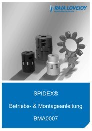
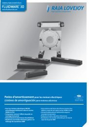
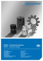
LK-Torsionskupplungssystem LK Torsional Coupling system<br />
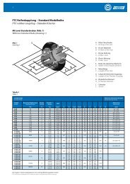
LK-Kupplungen-Leistungsdaten LK performance data<br />
Kupplung<br />
Größe<br />
Coupling<br />
size<br />
Verlagerung:<br />
NENN-<br />
Drehmoment<br />
NOM torque<br />
Da die Kupplung sehr torsionssteif ist, ist sie auch in radialer Richtung sehr<br />
steif und deshalb für genau ausgerichtete Antriebe (flanschmontiert) geeignet.<br />
Die Kupplung kann kleine Radial- und Winkelverlagerungen ausgleichen,<br />
wie sie normalerweise an flanschmontierten Antrieben erwartet<br />
werden. In der Axialrichtung kann die Nabe sich frei bewegen und kann<br />
einige Millimeter von der idealen axialen Position selbst über den Flansch<br />
hinausragend montiert werden. Bei hochbelasteten Kupplungen wird jedoch<br />
empfohlen, dass die Mitnehmer jederzeit vollständig im Eingriff sind.<br />
Montage:<br />
In den meisten Fällen ist der Durchmesser des Nabensterns kleiner als der<br />
zentrale Aufnahmedurchmesser des Pumpenflansches (der Nabenstern<br />
passt durch die Bohrung im Flansch, der die Pumpe mit dem Schwungradgehäuse<br />
verbindet). Der Durchmesser des Nabensterns ist immer etwas<br />
kleiner als die normale Größe der Kupplung (der Rotationsdurchmesser des<br />
Nabensterns für die LF-K-100 ist < 100 mm und passt durch die Bohrung in<br />
der Pumpen-Montageplatte, vorausgesetzt, dass diese einen Durchmesser<br />
von 100 mm oder darüber hat). In diesem Fall kann die Montage wie folgt<br />
erfolgen: (Siehe die Abbildung unten links)<br />
1. Den Kupplungsflansch an das Schwungrad schrauben.<br />
2. Die Pumpenmontageplatte auf das Schwungradgehäuse schrauben.<br />
3. Die Kupplung auf die Pumpenwelle schieben und sichern.<br />
4. Zum Eingriff der Kupplung mit der Pumpe, die Pumpe durch die Pumpenmontageplatte<br />
beischieben.<br />
In einigen Fällen, bei denen der Nabenstern-Durchmesser größer als die<br />
Bohrung in der Pumpenmontageplatte ist, sollte die Montage wie folgt<br />
durchgeführt werden: (Siehe die Abbildung unten in der Mitte)<br />
1. Den Kupplungsflansch an das Schwungrad schrauben.<br />
2. Die Pumpenmontageplatte an der Pumpe festschrauben.<br />
3. Die Kupplungsnabe auf die Pumpenwelle schieben und sichern.<br />
4. Die Pumpe mit der Montageplatte beischieben, bis die Kupplung eingreift<br />
und dann die Montageplatte im Schwungradgehäuse fixieren. Die<br />
komplette Baugruppe am Schwungradgehäuse festschrauben.<br />
Axiale Sicherung der Nabe<br />
Die Nabe kann sich in ihrer axialen Position frei einstellen, da kein axialer<br />
Anschlag vorhanden ist. Daher muss die Nabe auf der Pumpenwelle axial<br />
nicht gesichert werden. Für beste Ergebnisse verwenden Sie unser bewährtes<br />
L-Loc-Klemmsystem. Für leichte Antriebe, bei denen die Pumpenwelle<br />
mit einem Absatz versehen ist, kann es vorteilhaft sein, die Nabe mit<br />
einer Schraube und Scheibe am Wellenende festzuschrauben, vorausgesetzt,<br />
die Welle ist mit einer Gewindebohrung ausgestattet.<br />
MAX MAX Dynamische Torsionssteife Dynamic torsional stiffness<br />
Drehmoment<br />
Torque<br />
Drehzahl<br />
Speed<br />
C Tdyn (kNm/rad)<br />
Relative<br />
Dämpfung<br />
Relative<br />
damping<br />
TKN TKmax (U/min) (RPM) 0.25 TKN 0.50 TKN 0.75 TKN 1.00 TKN Ψ<br />
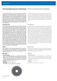
LK80 125 Nm 330 Nm 6000 44 50 72 96<br />
LK100 400 Nm 800 Nm 5000 55 62 90 120<br />
LK125 800 Nm 1600 Nm 4500 155 180 315 460 0.4<br />
LK150 1200 Nm 3000 Nm 4000 260 280 420 900<br />
LK150D 2400 Nm 6000 Nm 4000 520 560 840 1800<br />
Misalignment:<br />
As the coupling is torsionally very stiff, it is also very stiff in the radial direction. It<br />
is suitable for accurately aligned drives, (flange mounted). The coupling is able to<br />
compensate for the small radial and angular misalignments that must normally<br />
be expected on flange mounted drives. In the axial direction, the hub can move<br />
freely and be located a few millimeters from the ideal axial position, even to the<br />
point of protruding out of the flange. However, for highly loaded couplings, it is<br />
recommended that the dogs be completely engaged at all times.<br />
Mounting:<br />
In most cases, the diameter of the hubstar is smaller than the center locating<br />
diameter of the pump flange (the hubstar passes through bore in the flange<br />
which connects the pump with the flywheel housing). The diameter of the hubstar<br />
is always a little smaller than the normal size of the coupling (the rotation<br />
diameter of the hubstar for LF-K-100 is < 100 mm; it will pass through the bore<br />
in the pump mounting plate provided it is 100 mm in diameter or greater). In<br />
this case the installation can be carried out as follows: (See bottom left picture)<br />
1. Bolt the coupling flange onto the flywheel.<br />
2. Bolt the pump mounting plate onto the flywheel housing.<br />
3. Fit coupling onto the pump shaft and secure.<br />
4. Offer up pump to engage coupling and pump in the pump mounting plate.<br />
For the occasional case where the hubstar diameter is larger than the bore in<br />
the pump mounting plate, the installation should be carried out as follows: (See<br />
bottom center picture)<br />
1. Bolt the coupling flange onto the flywheel.<br />
2. Bolt pump mounting plate to pump.<br />
3. Fit coupling hub onto the pump shaft and secure.<br />
4. Offer up pump and mounting plate so coupling engages and locate the pump<br />
mount plate in the flywheel housing. Bolt complete assembly to flywheel housing.<br />
Axial securing of hub<br />
The hub can adjust its axial position freely as there is no axial stop. Therefore, the<br />
hub has to be secured onto the pump shaft axially. For best results use our proven<br />
L-Loc clamping system. For light drives where the pump shaft has a shoulder it<br />
can be sufficient to clamp the hub against the shoulder using a bolt and washer<br />
fastened onto the end of the pump shaft, provided it has a tapped hole.