Sie wollen auch ein ePaper? Erhöhen Sie die Reichweite Ihrer Titel.
YUMPU macht aus Druck-PDFs automatisch weboptimierte ePaper, die Google liebt.
9<br />
Auswahl der Torsionskupplung<br />
für Verbrennungsmotoranwendungen<br />
4. Kritische Drehzahlen aufgrund der Resonanz bestimmen<br />
Die Kupplungssteife auswählen, so dass das System nicht im hohen Resonanzbereich<br />
läuft, oder mit anderen Worten sicherstellen, dass normale Betriebs-<br />
und Leerlaufdrehzahlen sich nicht in der Nähe von kritischen Drehzahlen<br />
befinden.<br />
Kritische Drehzahlen stehen in Beziehung mit der natürlichen Frequenz<br />
des Systems und der generierten Anzahl der Impulse oder Erregungen pro<br />
Umdrehung i (Reihenfolge). Zur Analyse ist die Anwendung möglichst auf<br />
ein 2-Massen-System zu reduzieren und nachfolgende Gleichung anzuwenden.<br />
wobei<br />
nR =<br />
√ CTdyn<br />
60<br />
JA + JL<br />
×<br />
2π × i JA × JL<br />
nR = die kritische Resonanzdrehzahl des Systems (U/min),<br />
CTdyn = die dynamische Torsionssteife der Kupplung (Nm/rad),<br />
JA = das Massenträgheitsmoment der Antriebsseite (kg-m²),<br />
und<br />
JL = das Massenträgheitsmoment der Lastseite (kg-m²) ist.<br />
In diesem Modell stellt die Kupplung eine Feder dar, welche die<br />
Torsionsschwingungen des Motors und der Schwungscheibe auf der<br />
einen und die der getriebenen Einheit auf der anderen Seite<br />
kontrolliert.<br />
JA<br />
CTdyn<br />
Verwenden Sie die Werte der Drehfedersteifigkeiten aus der Leistungsdatentabelle<br />
(Seite 12). Massenträgheitswerte können von den betreffenden<br />
Motoren- oder Maschinenherstellern angefordert werden.<br />
Im Allgemeinen sollten Dauerdrehzahlen für einen sicheren Betrieb<br />
mit niedrigen Resonanzen das 1,5- bis 2-fache der hauptsächlichen kritischen<br />
Drehzahl betragen.<br />
5. Zulässiger ständiger Vibrationsdrehmoment<br />
Die Amplitude eines vom System generierten ständig schwingenden Vibrationsdrehmoments<br />
(T W ) darf die Werte der Kupplung (T KW ) bei einer besonderen<br />
Dauerfrequenz (U/min) und Temperatur nicht überschreiten. Dieses Drehmoment<br />
ist der Grundlast (T LN ) überlagert (koexistiert damit).<br />
T KW ≥ T W × S t × S f<br />
wobei<br />
T KW = Kupplungsauslegung für ein ständig schwingendes Drehmomen t bei<br />
10 Hz<br />
und<br />
S f = der Frequenzfaktor, der die Betriebsfrequenz mit der Auslegung der<br />
Kupplung bei 10 Hz in Verbindung bringt, ist (siehe Abb. 3. Seite 14).<br />
Die Magnitude des ständig schwingenden Drehmoments (T W ) hängt von<br />
dem Verstärkungsfaktor (V) ab, der auf dem Abstand der Betriebsdrehzahl<br />
im Dauerzustand n von der Resonanzdrehzahl n R basiert:<br />
V ≈<br />
1<br />
|1-(n/n R ) 2 |<br />
6. Andere Erwägungen<br />
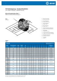
Beachten Sie die Leistungsdatentabellen, Abbildungen und Abmessungstabellen<br />
für die endgültige Kupplungsauswahl, damit die Maße (Außendurchmesser,<br />
Länge, Bohrungsmaße etc.), die Maximaldrehzahlen und die zulässigen<br />
Verlagerungen den Anwendungsbedingungen entsprechen.<br />
JL<br />
(siehe Abb. 4, Seite 14).<br />
Torsional Coupling selection<br />
for internal combustion engine applications<br />
4. Determine critical speeds due to resonance<br />
Select coupling stiffness so that the system does not run at high resonance, or<br />
in other words, make sure normal running and idle speeds are not at or near<br />
critical speeds.<br />
Critical speeds are related to the system natural frequency and the number of<br />
pulses or excitations generated per revolution i (order). For analysis, if possible,<br />
reduce the application to a 2-mass system and apply the following equation<br />
on next page.<br />
where<br />
n R = the critical resonance speed of the system (RPM),<br />
C Tdyn = the dynamic torsional stiffness of the coupling (Nm/rad),<br />
J A = the mass moment of inertia for the drive side (kg-m²),<br />
and<br />
J L = the mass moment of inertia for the load side (kg-m² ).<br />
The coupling would be modeled as the spring controlling<br />
torsional oscillations of the engine and flywheel on one side and<br />
the driven equipment on the other:<br />
Use the dynamic torsional stiffness values from the Performance Data table (p.<br />
12). Mass moment of inertia values may be obtained from the respective engine<br />
and equipment manufacturers.<br />
Generally, system steady-state operating speeds should be 1.5 to 2<br />
times the major critical speed for safe, low-resonance operation.<br />
5. Allowable continuous vibratory torque<br />
The amplitude of the continuously oscillating (vibratory) torque generated<br />
in the system (T W ) must not exceed the coupling's rating (T KW ) at a particular<br />
steady-state frequency (RPM) and temperature. This torque is superimposed on<br />
(co-exists with) the basic load (T LN ).<br />
T KW ≥ T W × S t × S f<br />
where<br />
T KW = coupling rating for continuously oscillating torque at 10Hz<br />
and<br />
S f = the frequency factor that relates the operating frequency to the coupling’s<br />
10Hz rating (see fig. 3, p.14).<br />
The magnitude of the continuously oscillating torque (T W ) is dependent on an<br />
amplifying factor (V) based on the distance of the system steady-state operating<br />
speed n from the resonance speed n R :<br />
V ≈<br />
1<br />
|1-(n/n R ) 2 |<br />
n R =<br />
J A<br />
60<br />
C Tdyn<br />
(see fig. 4, p.14).<br />
√ C Tdyn ×<br />
6. Other considerations<br />
Refer to the Performance Data tables, figures, and dimension tables to make<br />
certain final coupling selection meets application constraints for envelope<br />
(O.D., length, bore dimensions, etc.), maximum speed limitations and allowable<br />
misalignment<br />
J L<br />
J A + J L<br />
2π × i J A × J L