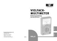
VM 22 K - Hartig + Helling GmbH & Co. KG
VM 22 K - Hartig + Helling GmbH & Co. KG
VM 22 K - Hartig + Helling GmbH & Co. KG

Sie wollen auch ein ePaper? Erhöhen Sie die Reichweite Ihrer Titel.
YUMPU macht aus Druck-PDFs automatisch weboptimierte ePaper, die Google liebt.
Measuring<br />
range<br />
Measured value<br />
on black AC V scale<br />
10 V Value indicated on<br />
lower scale, read off<br />
directly<br />
50 V Value indicated on<br />
middle scale, read off<br />
directly<br />
250 V Value indicated on<br />
upper scale, read off<br />
directly<br />
500 V Value indicated on<br />
middle scale x10<br />
Max. input voltage 500 V AC at<br />
30-1000 Hz.<br />
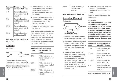
DC voltage<br />
Test circuit:<br />
+<br />
–<br />
U= <strong>VM</strong> <strong>22</strong> K<br />
1. <strong>Co</strong>nnect the black measuring<br />
cable to the ground jack “COM”.<br />
2. <strong>Co</strong>nnect the red measuring cable<br />
to the “V Ω mA” socket.<br />
3. Set the selector to the “V ”<br />
range and select a measuring<br />
range whose upper limit<br />
corresponds to the maximum<br />
DC voltage.<br />
4. <strong>Co</strong>nnect the measuring lines to<br />
the measuring circuit. Ensure<br />
the correct polarity of the<br />
measuring tips (+/-).<br />
5. Switch on the measuring circuit<br />
as required.<br />
Read the measured value from the<br />
black scale. If the pointer moves<br />
to the left, the polarity of the<br />
measuring tips is wrong. Switch<br />
off the measuring circuit and<br />
re-correct the measuring tips to<br />
the measuring circuit.<br />
Measuring<br />
range<br />
Measured value<br />
on black DC V.A<br />
scale<br />
10 V Value indicated on<br />
lower scale, read off<br />
directly<br />
50 V Value indicated on<br />
middle scale, read off<br />
directly<br />
250 V Value indicated on<br />
upper scale, read off<br />
directly<br />
500 V Value indicated on<br />
middle scale x10<br />
directly<br />
Max. input voltage 500 V DC.<br />
Measuring DC current<br />
Test circuit:<br />
+<br />
–<br />
U= <strong>VM</strong> <strong>22</strong> K<br />
load, e. g.<br />
incandescent lamp<br />
1. <strong>Co</strong>nnect the black measuring<br />
cable to the ground jack “COM”.<br />
2. <strong>Co</strong>nnect the red measuring cable<br />
to the “V Ω mA” socket, if the<br />
maximum anticipated current is<br />
500 mA. Otherwise use jack<br />
“10 A”.<br />
3. Set the selector to the “A ”<br />
range and select a measuring<br />
range whose upper limit<br />
corresponds to the maximum<br />
DC current voltage. If you do not<br />
know this, select the highest<br />
value. When using jack “10 A”,<br />
set the measuring range selector<br />
to range “10 A”.<br />
4. Break the measuring circuit and<br />
connect the measuring<br />
instrument in series with the<br />
load.<br />
Read the current value from the<br />
black scale.<br />
Important!<br />
For measurements up to 500 mA,<br />
the unit is protected by an<br />
internal fuse (0.5 A/250 V quick<br />
acting). The 10 A range is not<br />
protected. You should therefore<br />
ensure connections are correct,<br />
otherwise accidents may occur.<br />
You should only exchange spent<br />
fuses for fuses of the same type.<br />
Measuring<br />
range<br />
Measured value on<br />
black DC V.A scale<br />
5 mA Value indicated on<br />
middle scale :10<br />
50 mA Value indicated on<br />
middle scale, read off<br />
directly<br />
500 mA Value indicated on<br />
middle scale x10<br />
10 A Value indicated on<br />
upper scale, read off<br />
directly<br />
Max. permissible current 10 A.<br />
14<br />
15