EC-RADIALVENTILATOREN mit integrierter ... - Rosenberg
EC-RADIALVENTILATOREN mit integrierter ... - Rosenberg
EC-RADIALVENTILATOREN mit integrierter ... - Rosenberg

Sie wollen auch ein ePaper? Erhöhen Sie die Reichweite Ihrer Titel.
YUMPU macht aus Druck-PDFs automatisch weboptimierte ePaper, die Google liebt.
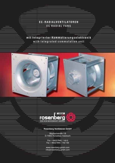
<strong>EC</strong>-<strong>RADIALVENTILATOREN</strong><br />
<strong>EC</strong> RADIAL FANS<br />
<strong>mit</strong> <strong>integrierter</strong> Kommutierungselektronik<br />
with integrated commutation unit<br />
<strong>EC</strong>OFIT<br />
ETRI<br />
THE AIR MOVEMENT GROUP<br />
<strong>Rosenberg</strong> Ventilatoren GmbH<br />
Maybachstraße 1/9<br />
D-74653 Künzelsau-Gaisbach<br />
Fon +49(0)7940 / 142-0<br />
Fax +49(0)7940 / 142-125<br />
www.rosenberg-gmbh.com<br />
info@rosenberg-gmbh.com
GKH_355<br />
GKHR<br />
110 67<br />
M10 (8x45°)<br />
Tiefe / depth 25mm<br />
10<br />
359<br />
235<br />
219<br />
238<br />
315<br />
356 (6x60°)<br />
382<br />
70<br />
164<br />
6<br />
1,5<br />
270<br />
252<br />
331<br />
GKHM<br />
11<br />
359<br />
219<br />
356<br />
382<br />
346<br />
401<br />
450<br />
450<br />
500<br />
Andere Plattenabmessungen auf Anfrage / other dimensions on request<br />
17
26<br />
GKH_500
GKH_500<br />
27
28<br />
GKH_560
GKH_560<br />
29
30<br />
GKH_630
GKH_630<br />
GKHR<br />
Andere Plattenabmessungen auf Anfrage / other dimensions on request<br />
31
Anschlußdiagramm<br />
Connection diagram<br />
U<br />
GND-PE<br />
< 15 V<br />
32
Applikationen<br />
Die <strong>EC</strong>-Ventilatoren <strong>mit</strong> <strong>integrierter</strong> Leistungselektronik<br />
bieten die Möglichkeit des direkten Anschluss von<br />
externen Sollwertvorgaben zur Regelung der Drehzahl.<br />
Die aufgeführten Applikationen stellen Verwendungsmöglichkeiten<br />
dar, wie sie üblicherweise in lüftungstechnischen<br />
Anlagen verwendet werden. In den Illustrationen<br />
ist ein Potentiometer als Sollwertvorgabe dargestellt.<br />
Alternativ kann jedoch immer ein:<br />
- externes Spannungssignal (0-10V)<br />
- externes PWM-Signal<br />
verwendet werden.<br />
Folgende Anwendungen sind kurz beschrieben.<br />
- Drehzahlvorgabe <strong>mit</strong> externem Potentiometer /<br />
0-10 V Signal / PWM- Signal<br />
- Konstantdruckregelung<br />
- Konstantvolumenstromregelung durch<br />
Differenzdruckmessung an der Einströmdüse.<br />
Optional: Anzeige des Volumenstroms am<br />
Differenzdrucksensor.<br />
Applications<br />
The <strong>EC</strong> fans with integrated commutation unit offer the<br />
possibility of the direct connection of external nominal<br />
value settings for the regulation of the speed. The<br />
specified applications represent ranges of application,<br />
how they are usually used in ventilation installation plants.<br />
In the illustrations a potentiometer is represented as<br />
desired value default.<br />
Alternatively can however always:<br />
- external voltage signal (0-10V)<br />
- external PWM<br />
are used.<br />
The following applications are briefly described.<br />
- Number of revolutions default with external<br />
potentiometer / 0-10 V signal / PWM signal<br />
- constant pressure control<br />
- constant flow rate regulation by differential<br />
pressure measurement at inlet cone.<br />
Optionally: Display of the flow rate at the<br />
differential pressure sensor.<br />
Drehzahlvorgabe <strong>mit</strong> externem Potentiometer /<br />
0-10 Volt Signal / PWM- Signal<br />
Number of revolutions default with external<br />
potentiometer / 0-10 V signal / PWM signal<br />
3<br />
ANALOG 1<br />
GND/0-10V/+10V<br />
2<br />
ANALOG 1<br />
GND/0-10V<br />
2<br />
ANALOG 1<br />
GND/PWM<br />
4<br />
3*L+PE<br />
3~380 - 480 V<br />
50/60Hz<br />
Mains<br />
4<br />
3*L+PE<br />
3~380 - 480 V<br />
50/60Hz<br />
Mains<br />
4<br />
3*L+PE<br />
3~380 - 480 V<br />
50/60Hz<br />
Mains<br />
a) b) c)<br />
a) Drehzahlvorgabe durch externes Potentiometer<br />
b) Drehzahlvorgabe durch 0-10 Volt Signal generiert<br />
aus einer übergeordneten DDC.<br />
c) Drehzahlvorgabe durch PWM Signal generiert<br />
durch einen Kompaktregler.<br />
Das Potentiometer steht in den nachfolgend aufgeführten<br />
Illustrationen stellvertretend für die drei im<br />
Bild a) - c) dargestellten Drehzahlvorgaben.<br />
a) No. of revolutions default by ext. potentiometer<br />
b) number of revolutions default by<br />
0-10 V signal generated from a superior DDC.<br />
c) number of revolutions default by PWM signal<br />
generated by a compact controller.<br />
The potentiometer stands in the in the following<br />
performed illustrations on behalf for three in the<br />
picture a) - c) to shown speed default.<br />
33
Konstantdruckregelung<br />
Constant Pressure Control<br />
1 Druckentnahme (Kanal)<br />
2 Atmosphärendruck<br />
+<br />
2<br />
p<br />
1<br />
3<br />
ANALOG 1<br />
GND/0-10V/+10V<br />
ANALOG 2<br />
GND/0-10V/+24V<br />
3<br />
4<br />
3*L+PE<br />
3~380 - 480 V<br />
50/60Hz<br />
Mains<br />
Anwendung bei Konstant(über)druckregelung im Klimagerät<br />
oder in der Prozesslufttechnik wenn konstante<br />
Anlagendrücke gefordert werden.<br />
Application with constant pressure control in the air<br />
conditioner or in the processing air technology if constant<br />
plant pressures is to be demanded.<br />
1 Druckentnahme (Kanal)<br />
2 Atmosphärendruck<br />
2<br />
+<br />
p<br />
1<br />
3<br />
ANALOG 1<br />
GND/0-10V/+10V<br />
ANALOG 2<br />
GND/0-10V/+24V<br />
3<br />
4<br />
3*L+PE<br />
3~380 - 480 V<br />
50/60Hz<br />
Mains<br />
Anwendung bei Konstant(unter)druckregelung im Klimagerät<br />
oder in der Prozesslufttechnik. Z.B. Zentralentlüftung<br />
über gemeinsames Rohr- oder Kanalsystem<br />
wenn verstellbare Ventile oder Klappen verwendet<br />
werden.<br />
Application with constant pressure control in the air<br />
conditioner or in the processing air technology. E.G.<br />
central exhaust over common tubing or duct system if<br />
adjustable valves or flaps to be used.<br />
34
Konstantvolmenstromregelung durch Differenzdruckmessung<br />
an der Einströmdüse<br />
Constant flow rate regulation by differential<br />
pressure measurement at the inlet cone<br />
1 Druckentnahme Düse<br />
2 Ringleitung<br />
3 Druckentnahme Saugraum<br />
+<br />
p<br />
3<br />
2<br />
1<br />
3<br />
ANALOG 1<br />
GND/0-10V/+10V<br />
ANALOG 2<br />
GND/0-10V/+24V<br />
3<br />
4<br />
3*L+PE<br />
3~380 - 480 V<br />
50/60Hz<br />
Mains<br />
Durch eine Ringmessleitung an der Einströmdüse kann<br />
der Volumenstrom des Ventilators er<strong>mit</strong>telt werden (siehe<br />
Abschnitt Volumenstrom-Messeinrichtung im Katalog vorspann).<br />
Die Auswahl des benötigten Differenzdrucksensor<br />
p erfolgt dabei nach folgendem Zusammenhang.<br />
The flow rate of the fan can be determined by a circular<br />
lead at the inlet cone (see section Air volume testing<br />
device in catalogue prefix). The choice of the required<br />
difference pressure sensor p occurs after the following<br />
connection.<br />
Der Düsenbeiwert k10 ist dem verwendeten Ventilator<br />
zugeordnet und ist jeweils unten rechts am Kennlinienfeld<br />
angegeben. Der Volumenstrom [V] ist der Ventilatorkennlinie<br />
zu entnehmen. Der Wert des benötigten<br />
Differenzdrucksensor ist immer rechnerisch zu er<strong>mit</strong>teln,<br />
da der benötigte Differenzdruck den in der Kennlinie<br />
angegebenen statischen Druck pfa bei weitem<br />
überschreiten kann.<br />
Bei der Verwendung des Differenzdrucksensors RVT<br />
(siehe Zubehör) besteht die Möglichkeit den eingestellten<br />
Volumenstrom direkt am Sensor abzulesen. Beim<br />
Differenzdrucksensor RVT muss zu diesem Zweck nur<br />
der entsprechende Düsenbeiwert k10 eingestellt werden.<br />
Der Volumenstrom wird in der Einheit m³/h angezeigt.<br />
The calibration factor k10 is assigned to the used fan and<br />
is given in each case below on the right in the<br />
characteristic diagram. The volume stream [V] is to be<br />
taken from the air performance curves. The value of the<br />
required difference pressure sensor is to be determined<br />
always mathematically, because the required difference<br />
pressure can cross static pressure given in the air<br />
performance curve by far.<br />
By the use of the difference pressure sensor RVT (see<br />
accessories) the possibility exists to read the opposed<br />
volume stream directly in the sensor. By the difference<br />
pressure sensor RVT only the suitable calibration factor<br />
k10 must be put for this purpose. The volume stream is<br />
indicated in the unity m ³ / h.<br />
35
Differenzdrucksensor<br />
Differential pressure sensor<br />
Messbereiche / Measuring range:<br />
PU 5 0 - 500 Pa Art.-Nr. H40-00004<br />
PU 10 0 - 1000 Pa Art.-Nr. H40-00005<br />
PU 20 0 - 2000 Pa Art.-Nr. H40-00020<br />
PU 40 0 - 4000 Pa Art.-Nr. H40-00040<br />
Sensor <strong>mit</strong> Membranmesswerk zur Messwertübertragung<br />
von Druck, Unterdruck oder Differenzdruck nicht<br />
aggressiver Gase.<br />
Differenzdrucksensor <strong>mit</strong> LCD Display<br />
Sensor with lead diaphragm element for trans<strong>mit</strong>ting of<br />
pressure, draught, or differential pressure of non-aggressive<br />
gases.<br />
Differential pressure sensor with LCD display<br />
Messbereiche / Measuring range:<br />
RVT 500 0 - 500 Pa Art.-Nr. H40-00021<br />
RVT 1000 0 - 1000 Pa Art.-Nr. H40-00022<br />
RVT 2000 0 - 2000 Pa Art.-Nr. H40-00023<br />
Sensor <strong>mit</strong> LCD- Display zur Anzeige des Differenzdruck.<br />
Bei Verwendung einer Einströmdüse <strong>mit</strong> Ringmessleitung<br />
kann der Volumenstrom direkt auf dem Display des<br />
Sensors angezeigt werden. Der Druck wird in der Einheit<br />
[P ], der Volumenstrom in der Einheit [m³/h] angegeben.<br />
a<br />
Potentiometer im Gehäuse<br />
Sensor with LCD display for monitoring the differential<br />
pressure. The flow rate of the fan can be determined by a<br />
circular lead at the inlet cone. In this case the air volume is<br />
directly displayed on the sensor. The pressure is<br />
indicated in the unit [ P ], the flow rate in the unit [ m³/h ].<br />
a<br />
Potentiometer in the housing<br />
Art.-Nr. H55-00053<br />
Potentiometer 10 kOhm im Gehäuse IP 54 montiert.<br />
Drehbereich 0 - 270°. Skalierung 0 - 100% zur stufenlosen<br />
manuellen Drehzahlvorgabe.<br />
Abmessungen (B x H x T): 65 x 65 x 60<br />
Potentiometer 10 kOhm in the housing; IP 54. Range of<br />
rotation 0 - 270°. Scaling 0 - 100%.<br />
Dimensions (W xHxD):65x65x60<br />
Art.-Nr. H55-00055<br />
Potentiometer 10kOhm im Gehäuse; IP 30 montiert.<br />
Skalierung aufsteigend, zur stufenlosen manuellen<br />
Drehzahlvorgabe. Wippschalter zum Schalten der<br />
Freigabe des <strong>EC</strong>- Motors sowie grüne und rote LED zur<br />
Statusanzeige (Betrieb / Störung).<br />
Potentiometer 10 kOhm in the housing; IP 30. Rise<br />
scaling for a manuel steples rpm arrangement. Switch to<br />
connect enable (start / Stop). LED green and red for <strong>EC</strong>-<br />
Motor status /ready or error<br />
36