Catalogue sheet / Katalogblatt 2BE3 & NPR2
Catalogue sheet / Katalogblatt 2BE3 & NPR2
Catalogue sheet / Katalogblatt 2BE3 & NPR2

Sie wollen auch ein ePaper? Erhöhen Sie die Reichweite Ihrer Titel.
YUMPU macht aus Druck-PDFs automatisch weboptimierte ePaper, die Google liebt.
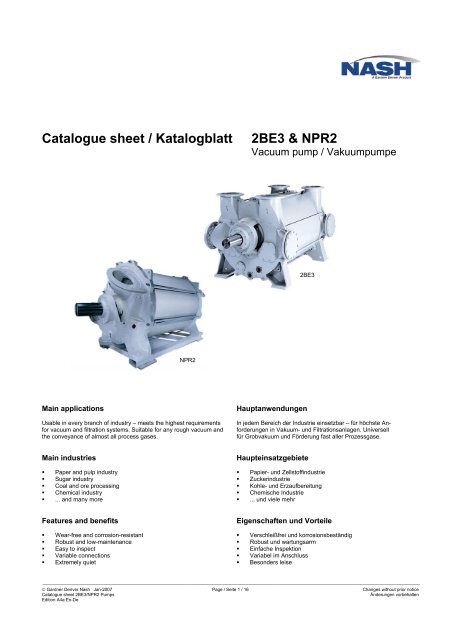
<strong>Catalogue</strong> <strong>sheet</strong> / <strong>Katalogblatt</strong><br />
<strong>2BE3</strong> & <strong>NPR2</strong><br />
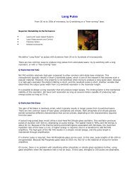
Vacuum pump / Vakuumpumpe<br />
<strong>2BE3</strong><br />
<strong>NPR2</strong><br />
Main applications<br />
Usable in every branch of industry – meets the highest requirements<br />
for vacuum and filtration systems. Suitable for any rough vacuum and<br />
the conveyance of almost all process gases.<br />
Hauptanwendungen<br />
In jedem Bereich der Industrie einsetzbar – für höchste Anforderungen<br />
in Vakuum- und Filtrationsanlagen. Universell<br />
für Grobvakuum und Förderung fast aller Prozessgase.<br />
Main industries<br />
• Paper and pulp industry<br />
• Sugar industry<br />
• Coal and ore processing<br />
• Chemical industry<br />
• ... and many more<br />
Haupteinsatzgebiete<br />
• Papier- und Zellstoffindustrie<br />
• Zuckerindustrie<br />
• Kohle- und Erzaufbereitung<br />
• Chemische Industrie<br />
• ... und viele mehr<br />
Features and benefits<br />
• Wear-free and corrosion-resistant<br />
• Robust and low-maintenance<br />
• Easy to inspect<br />
• Variable connections<br />
• Extremely quiet<br />
Eigenschaften und Vorteile<br />
• Verschleißfrei und korrosionsbeständig<br />
• Robust und wartungsarm<br />
• Einfache Inspektion<br />
• Variabel im Anschluss<br />
• Besonders leise<br />
_________________________________________________________________________________________________________________________________________________________<br />
© Gardner Denver Nash Jan-2007 Page / Seite 1 / 16 Changes without prior notice<br />
<strong>Catalogue</strong> <strong>sheet</strong> <strong>2BE3</strong>/<strong>NPR2</strong> Pumps<br />
Änderungen vorbehalten<br />
Edition A4a En-De
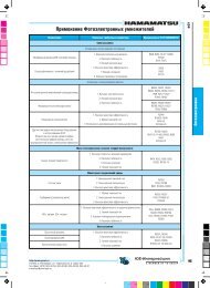
Performance curves • Kennlinien<br />
Performance range • Leistungsbereiche<br />
100.000<br />
m³/h<br />
<strong>NPR2</strong> 62 max.<br />
<strong>2BE3</strong> 72 max.<br />
<strong>2BE3</strong> 67 max.<br />
<strong>NPR2</strong> 62 min.<br />
<strong>2BE3</strong> 62 max.<br />
<strong>2BE3</strong> 72 min.<br />
<strong>2BE3</strong> 52 max.<br />
<strong>2BE3</strong> 67 min.<br />
10.000<br />
<strong>2BE3</strong> 42 max.<br />
<strong>2BE3</strong> 60 min.<br />
<strong>2BE3</strong> 50 min.<br />
<strong>2BE3</strong> 32 max.<br />
<strong>2BE3</strong> 40 min.<br />
<strong>2BE3</strong> 30 min.<br />
1.000<br />
150 200 250 350 450 550 650 750 850 950 1.000 1050<br />
Inlet pressure / Ansaugdruck p 1<br />
mbar abs.<br />
The performance range are based on operating conditions with saturated<br />
air at a temperature of 20 °C (68 °F), operating water at a temperature of<br />
15 °C (60 °F), and a discharge pressure of 1013 mbar (29.92 in Hg abs.).<br />
Tolerance + 5 % for inlet pressure ≥ 250 mbar, acc. to PNEUROP.<br />
Calculation of individual performance curves is done acc. to individual<br />
specification requirements.<br />
Die Leistungsbereiche gelten bei Ansaugen von Luft mit 100 % relativer<br />
Feuchte und 20 °C, Verdichtung auf 1013 mbar, sowie Wasser mit 15 °C<br />
als Betriebsflüssigkeit.<br />
Toleranz + 5 % für Ansaugdrücke ≥ 250 mbar, entsprechend PNEUROP.<br />
Die Berechnung der Einzelkennlinien erfolgt entsprechend der Spezifikationsanforderungen<br />
des Betreibers.<br />
_________________________________________________________________________________________________________________________________________________________<br />
© Gardner Denver Nash Jan-2007 Page / Seite 2 / 16 Changes without prior notice<br />
<strong>Catalogue</strong> <strong>sheet</strong> <strong>2BE3</strong>/<strong>NPR2</strong> Pumps<br />
Änderungen vorbehalten<br />
Edition A4a En-De
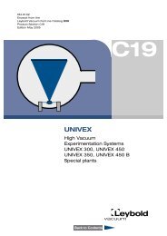
Power requirement • Leistungsbedarf<br />
900<br />
kW<br />
800<br />
700<br />
2<br />
1<br />
1 = <strong>NPR2</strong> 62 min / max<br />
2 = <strong>2BE3</strong> 72 min / max<br />
3 = <strong>2BE3</strong> 67 min / max<br />
4 = <strong>2BE3</strong> 62 min / max<br />
5 = <strong>2BE3</strong> 50 min...<strong>2BE3</strong> 52 max<br />
6 = <strong>2BE3</strong> 40 min...<strong>2BE3</strong> 42 max<br />
7 = <strong>2BE3</strong> 30 min...<strong>2BE3</strong> 32 max<br />
600<br />
3<br />
500<br />
4<br />
400<br />
5<br />
300<br />
6<br />
200<br />
100<br />
7<br />
0<br />
150 200 250 350 450 550 650 750 850 950 1.000 1050<br />
Inlet pressure / Ansaugdruck p 1<br />
mbar abs.<br />
_________________________________________________________________________________________________________________________________________________________<br />
© Gardner Denver Nash Jan-2007 Page / Seite 3 / 16 Changes without prior notice<br />
<strong>Catalogue</strong> <strong>sheet</strong> <strong>2BE3</strong>/<strong>NPR2</strong> Pumps<br />
Änderungen vorbehalten<br />
Edition A4a En-De
Materials • Werkstoffe<br />
Part Teil Material of construction - Werkstoffkombination<br />
Cast iron Cast iron - Stainless steel combination Stainless steel<br />
Gusseisen Gusseisen - Edelstahl - Kombination Edelstahl<br />
B K M N E H<br />
Order No. Order No. Order No. Order No. Order No. Order No.<br />
Bestell-Nr. Bestell-Nr. Bestell-Nr. Bestell-Nr. Bestell-Nr. Bestell-Nr.<br />
Vacuum pump • Vakuumpumpe<br />
Impeller Laufrad Spheroidal graphite<br />
cast iron<br />
ASTM A 536<br />
Grade 60-40-18<br />
Gusseisen mit<br />
Kugelgraphit<br />
EN-GJS-400-15/<br />
EN-JS1030<br />
(GGG-40 / 0.7040)<br />
Spheroidal graphite<br />
cast iron<br />
coated with ceramic 1)<br />
ASTM A 536<br />
Grade 60-40-18<br />
Gusseisen mit<br />
Kugelgraphit<br />
keramikbeschichtet 1)<br />
EN-GJS-400-15/<br />
EN-JS1030<br />
(GGG-40 / 0.7040)<br />
Stainless steel<br />
ASTM A 276 316Ti<br />
Nichtrostender Stahl<br />
X6CrNiMoTi17-12-2 / 1.4571<br />
Shaft Welle Carbon steel<br />
ASTM A 572 Grade 50<br />
Stahl<br />
S355J2G3 (St52-3N) / 1.0570<br />
Shaft bushing Schonbuchse <strong>2BE3</strong>: Stainless steel centrifugal casting<br />
ASTM 532 III A 25% Cr<br />
Nichtrostender Schleuderstahlguss<br />
GX120Cr29 / 1.4086<br />
NRP2:<br />
Coated shaft in the area of the shaft bushing<br />
Beschichtete Welle im Schonbuchsbereich<br />
Port plate Steuerscheibe Carbon steel<br />
ASTM A 283<br />
Grade C<br />
Stahl<br />
S235JRG2 (RSt37-2) /<br />
1.0038<br />
Stainless steel<br />
ASTM A 276 316L<br />
Nichtrostender Stahl<br />
X2CrNiMo17-12-2 /<br />
1.4404<br />
Carbon steel<br />
ASTM A 283<br />
Grade C<br />
Stahl<br />
S235JRG2 (RSt37-2) /<br />
1.0038<br />
Stainless steel<br />
ASTM A 276 316L<br />
Nichtrostender Stahl<br />
X2CrNiMo17-12-2 /<br />
1.4404<br />
Cone Konus Grey cast iron<br />
ASTM A 48 Class 30 B<br />
Gusseisen mit<br />
Lamellengraphit<br />
EN-GJL-200/<br />
EN-JL1030<br />
(GG-20 / 0.6020)<br />
-- -- -- -- --<br />
-- -- -- -- --<br />
Casing without<br />
partition wall<br />
Gehäuse ohne<br />
Zwischenwand<br />
Carbon steel, Polyisoprene (NR)-coated 2)<br />
ASTM A 283 Grade C + Polyisoprene (NR)<br />
Carbon steel, lined with stainless steel<br />
ASTM A 283 Grade C +<br />
ASTM A 276 316Ti<br />
Stahl mit Polyisoprenauskleidung 2)<br />
S235JR (St37-2) / 1.0037 + Polyisopren (NR)<br />
Stahl mit Edelstahlauskleidung<br />
S235JR (St37-2) / 1.0037 +<br />
X6CrNiMoTi17-12-2 / 1.4571<br />
Casing with<br />
partition wall<br />
Gehäuse mit<br />
Zwischenwand<br />
Carbon steel, Polyisoprene (NR)-coated 2)<br />
ASTM A 283 Grade C + Polyisoprene (NR)<br />
-- --<br />
(not for<br />
<strong>2BE3</strong> 30/32)<br />
(nicht für<br />
<strong>2BE3</strong> 30/32)<br />
Stahl, mit Polyisoprenauskleidung 2)<br />
S235JR (St37-2) / 1.0037 + Polyisopren (NR)<br />
-- --<br />
End shield Seitenschild Grey cast iron<br />
ASTM A 48 Class 30 B<br />
Gusseisen mit Lamellengraphit<br />
EN-GJL-200/EN-JL1030 (GG-20 / 0.6020)<br />
Stainless steel casting<br />
ASTM A 743-CF-3MN<br />
Nichtrostender<br />
Stahlguss<br />
GX5CrNiMoNb<br />
19-11-2 / 1.4581<br />
Packings for<br />
stuffing box<br />
Packungsringe<br />
für Stopfbuchse<br />
<strong>2BE3</strong>: Cotton impregnated (pH appr. 6-8)<br />
Baumwolle imprägniert (pH ca. 6-8)<br />
<strong>NPR2</strong>:<br />
PTFE, Graphite<br />
PTFE, Graphit<br />
Ramie-fibre with PTFE<br />
Ramiefaser mit PTFE<br />
An exploded view and further details you can find in our catalogue <strong>sheet</strong> for <strong>2BE3</strong>/<strong>NPR2</strong>-materials.<br />
Eine explodierte Darstellung und weitere Details entnehmen Sie bitte unserem <strong>2BE3</strong>/<strong>NPR2</strong>-Werkstoff-<strong>Katalogblatt</strong>.<br />
1) For coating with ceramic valid 2 % decrease in suction capacity and special warranty conditions. Please contact our Nash sales partner. Max. operating temperature 55 °C (131 °F) /<br />
Bei Keramikbeschichtung gelten 2 % Abschlag im Ansaugvolumenstrom und gesonderte Gewährleistungsbedingungen. Bitte sprechen Sie hierzu Ihren Nash-Vertriebspartner an.<br />
Max. Betriebstemperatur 55 °C.<br />
2) Max. operating temperature 65 °C (149 °F) / Max. Betriebstemperatur 65 °C.<br />
_________________________________________________________________________________________________________________________________________________________<br />
© Gardner Denver Nash Jan-2007 Page / Seite 4 / 16 Changes without prior notice<br />
<strong>Catalogue</strong> <strong>sheet</strong> <strong>2BE3</strong>/<strong>NPR2</strong> Pumps<br />
Änderungen vorbehalten<br />
Edition A4a En-De
Materials • Werkstoffe<br />
Part Teil Material of construction - Werkstoffkombination<br />
(Order code) (Kurzangabe) Cast iron Cast iron - Stainless steel combination Stainless steel<br />
Gusseisen Gusseisen - Edelstahl - Kombination Edelstahl<br />
B K M N E H<br />
Order No. Order No. Order No. Order No. Order No. Order No.<br />
Bestell-Nr. Bestell-Nr. Bestell-Nr. Bestell-Nr. Bestell-Nr. Bestell-Nr.<br />
Extended scope of supply • Erweiterter Lieferumfang<br />
Manifold<br />
(F44/F47)<br />
Hosenrohr<br />
(F44/F47)<br />
for/bei <strong>2BE3</strong> 30...32:<br />
for/bei <strong>2BE3</strong> 40...72:<br />
Grey cast iron<br />
ASTM A 48 Class 30 B<br />
Gusseisen mit Lamellengraphit<br />
EN-GJL-200/EN-JL1030 (GG-20 / 0.6020)<br />
Carbon steel<br />
ASTM A283 Grade C<br />
Stahl<br />
S235JRG1+CR / 1.0036 (UST37-2)<br />
Stainless steel<br />
ASTM A276 316Ti<br />
Edelstahl<br />
X6CrNiMoTi17-12-2 /<br />
1.4571<br />
Separator<br />
(F43)<br />
Abscheider<br />
(F43)<br />
Carbon steel<br />
ASTM A283 Grade C<br />
Stahl<br />
S235JRG1+CR / 1.0036 (UST37-2)<br />
Stainless steel<br />
ASTM A276 316Ti<br />
Edelstahl<br />
X6CrNiMoTi17-12-2 /<br />
1.4571<br />
Partial drain<br />
flange (F68)<br />
Teilentleerungsflansch<br />
(F68)<br />
Carbon steel<br />
ASTM A283 Grade C<br />
(only for <strong>2BE3</strong>) (nur bei <strong>2BE3</strong>) Stahl<br />
S235JRG1+CR / 1.0036 (UST37-2)<br />
Stainless steel<br />
ASTM A276 316Ti<br />
Edelstahl<br />
X6CrNiMoTi17-12-2 /<br />
1.4571<br />
_________________________________________________________________________________________________________________________________________________________<br />
© Gardner Denver Nash Jan-2007 Page / Seite 5 / 16 Changes without prior notice<br />
<strong>Catalogue</strong> <strong>sheet</strong> <strong>2BE3</strong>/<strong>NPR2</strong> Pumps<br />
Änderungen vorbehalten<br />
Edition A4a En-De
Model numbers and order information • Auswahl- und Bestelldaten<br />
Scope of supply Lieferumfang Material of construction - Werkstoffkombination<br />
(Details on page 4 - Details siehe Seite 4)<br />
Cast iron Cast iron - Stainless steel Stainless steel<br />
combinations<br />
Gusseisen Gusseisen - Edelstahl -<br />
Edelstahl<br />
Kombinationen<br />
B K; M; N E H<br />
Order No. Order No. Order No. Order No.<br />
Bestell-Nr. Bestell-Nr. Bestell-Nr. Bestell-Nr.<br />
Vacuum pump, basic design • Vakuumpumpe, Grundausführung<br />
Inlet flange N 1.0 at the top,<br />
discharge flange N 2.0 at the<br />
side.<br />
Flanges acc. to DIN EN<br />
1092-2<br />
Saugstutzen N 1.0 oben,<br />
Druckstutzen N 2.0 seitlich.<br />
Flansche nach DIN EN<br />
1092-2<br />
2 # # #<br />
<strong>2BE3</strong><br />
PL-6046a<br />
<strong>NPR2</strong><br />
Shaft sealing<br />
Wellendichtung<br />
Stuffing box<br />
with internal sealant 1)<br />
Stopfbuchse mit interner<br />
Sperrflüssigkeitsbenetzung 1)<br />
<strong>2BE3</strong> …-2BY4<br />
<strong>NPR2</strong> …-2BY4<br />
<strong>2BE3</strong> …-2<br />
--<br />
Y4<br />
<strong>2BE3</strong> …-2EY4<br />
--<br />
--<br />
--<br />
Stuffing box with external<br />
sealant supply<br />
Stopfbuchse mit externer<br />
Sperrflüssigkeitsversorgung<br />
<strong>2BE3</strong> …-2BY3<br />
<strong>NPR2</strong> …-2BY3<br />
<strong>2BE3</strong> …-2<br />
--<br />
Y3<br />
<strong>2BE3</strong> …-2EY3<br />
--<br />
<strong>2BE3</strong> …-2HY3<br />
--<br />
Mechanical seal, single<br />
acting, with external<br />
sealant supply<br />
Gleitringdichtung, einfachwirkend,<br />
mit externer Sperrflüssigkeitsversorgung<br />
Burgmann<br />
Crane<br />
<strong>2BE3</strong> …-2BY5<br />
or / oder<br />
<strong>2BE3</strong> …-2BY7<br />
<strong>2BE3</strong> …-2 Y5<br />
or / oder<br />
<strong>2BE3</strong> …-2 Y7<br />
<strong>2BE3</strong> …-2EY5<br />
or / oder<br />
<strong>2BE3</strong> …-2EY7<br />
<strong>2BE3</strong> …-2HY5<br />
or / oder<br />
<strong>2BE3</strong> …-2HY7<br />
<strong>NPR2</strong> o.r. / a.A. -- -- --<br />
Mechanical seal,<br />
double acting<br />
Gleitringdichtung,<br />
doppeltwirkend<br />
o.r. / a.A. o.r. / a.A. o.r. / a.A. o.r. / a.A.<br />
Casing<br />
Gehäuse<br />
without partition wall ohne Zwischenwand <strong>2BE3</strong> ..0-....<br />
<strong>NPR2</strong> ..0-….<br />
<strong>2BE3</strong> ..0-….<br />
--<br />
<strong>2BE3</strong> ..0-….<br />
--<br />
<strong>2BE3</strong> ..0-….<br />
--<br />
with partition wall 2) mit Zwischenwand 2) <strong>2BE3</strong> ..6-….<br />
<strong>NPR2</strong> o.r./a.A.<br />
<strong>2BE3</strong> ..6-….<br />
--<br />
o.r./a.A.<br />
--<br />
o.r./a.A.<br />
--<br />
Footnotes to page 6+7 / Fußnoten zu Seite 6+7:<br />
*) Add to the vacuum pump order no. a -Z and the order code(s) as given: <strong>2BE3</strong> 300-2BY4-Z<br />
An die Bestell-Nr. der Vakuumpumpe ein -Z und die Kurzangabe(n) wie folgt anzufügen: F43+F62<br />
1) Impregnating stuffing box with automatic lubrication / Stopfbuchsimprägnierung selbstschmierend.<br />
2) Design "with partition wall" for <strong>2BE3</strong> 30/32 on request / Ausführung "mit Zwischenwand“ für <strong>2BE3</strong> 30/32 auf Anfrage.<br />
3) Check, if partial drain flange (F68) is necessary (increasing of operation security) / Notwendigkeit Teilentleerung (F68) prüfen (Erhöhung der Betriebssicherheit) .<br />
4) F23 only for: <strong>2BE3</strong> ..0 -2B.., 0-2K.., 0-2M and 0-2N..; already included in <strong>2BE3</strong> ..0-2E.. and 0-2H..<br />
F23 nur für: <strong>2BE3</strong> ..0-2B.., 0-2K.. , 0-2M.. und 0-2N..; bei <strong>2BE3</strong> ..0-2E.. und 0-2H.. bereits enthalten.<br />
5) Lined with Polyisoprene (F27) is only deliverable with stuffing box with external sealant supply. Max. operating temperature 55 °C (131 °F). Gauge connection N8.7 not available.<br />
Polyisoprenauskleidung (F27) ist nur mit Stopfbuchse mit ext. Sperrflüssigkeitsversorgung lieferbar. Max. Betriebstemperatur 55 °C. Messanschluss N8.7 nicht vorhanden.<br />
6) F26 and/und F85: Max. operating temperature 55 °C (131 °F) / Max. Betriebstemperatur 55 °C.<br />
7) For coating with ceramic valid 2 % decrease in suction capacity and special warranty conditions. Please contact our Nash sales partner.<br />
Bei Keramikbeschichtung gelten 2 % Abschlag im Ansaugvolumenstrom und gesonderte Gewährleistungsbedingungen. Bitte sprechen Sie hierzu Ihren Nash-Vertriebspartner an.<br />
8) F85 in <strong>2BE3</strong> ...-..K.. already included (standard) / F85 in <strong>2BE3</strong> ...-..K.. bereits enthalten (Standard)<br />
_________________________________________________________________________________________________________________________________________________________<br />
© Gardner Denver Nash Jan-2007 Page / Seite 6 / 16 Changes without prior notice<br />
<strong>Catalogue</strong> <strong>sheet</strong> <strong>2BE3</strong>/<strong>NPR2</strong> Pumps<br />
Änderungen vorbehalten<br />
Edition A4a En-De
Extended scope of supply • Erweiterter Lieferumfang<br />
Scope of supply Lieferumfang Material of construction pump - Werkstoffkombination Pumpe<br />
(Details on page 4+5 - Details siehe Seite 4+5)<br />
Cast iron Cast iron - Stainless steel Stainless steel<br />
combinations<br />
Gusseisen Gusseisen - Edelstahl -<br />
Edelstahl<br />
Kombinationen<br />
B K; M; N E H<br />
for / für <strong>2BE3</strong><br />
Order code *) Order code *) Order code *) Order code *)<br />
Kurzangabe *) Kurzangabe *) Kurzangabe *) Kurzangabe *)<br />
Inlet flange N 1.0 and<br />
discharge flange N 2.01<br />
at the top:<br />
Saugstutzen N 1.0 und<br />
Druckstutzen N 2.01 oben:<br />
- without partial drain flange - ohne Teilentleerungsflansch F65 F65 F65 F65<br />
- with partial drain flange acc. to<br />
DIN EN 1092-1<br />
- mit Teilentleerungsflansch<br />
nach DIN EN 1092-1<br />
2 # # $<br />
F68 F68 F68 F68<br />
Discharge flange N2.01<br />
at the top, with mounted<br />
separator 3)<br />
Discharge flange N2.01<br />
at the top, with mounted<br />
manifold 3)<br />
Discharge flange N2.0 lateral,<br />
with mounted manifold suctionside<br />
Druckstutzen N2.01 oben,<br />
F43 F43 F43 F43<br />
abscheider 3)<br />
mit aufgebautem Flüssigkeits-<br />
Druckstutzen N2.01 oben,<br />
F47 F47 F47 F47<br />
mit aufgebautem Hosenrohr 3)<br />
Druckstutzen N2.0 seitlich,<br />
mit saugseitig aufgebautem<br />
Hosenrohr<br />
2 # # %<br />
F44 F44 F44 F44<br />
Casing lined<br />
with stainless steel 4)<br />
Gehäuse mit<br />
F23 F23 -- --<br />
Edelstahlauskleidung 4)<br />
End shields in grey cast iron lined<br />
with Polyisoprene (NR) 5)<br />
Seitenschilde aus GG mit<br />
F27 F27 F27 --<br />
Polyisoprenauskleidung (NR) 5)<br />
End shields in grey cast iron<br />
with partially ceramic coating<br />
(erosion protection) 6)<br />
Seitenschilde aus GG mit<br />
F26 F26 F26 F26<br />
(Erosionsschutz) 6)<br />
Teilkeramikbeschichtung<br />
Impeller coated with ceramic 6) 7) Laufrad keramikbeschichtet 6) 7) F85 F85 8) F85 F85<br />
Operating liquid self-priming<br />
(operation and test)<br />
Flange connection acc. to<br />
ANSI B16.5<br />
Betriebswasser selbstansaugend<br />
(Betrieb und Prüfung)<br />
Anschlussflansche nach<br />
ANSI B16.5<br />
F74 F74 F74 F74<br />
F62 F62 F62 F62<br />
Increase of operating liquid Kühlschaltung F64 F64 F64 F64<br />
Second shaft extension<br />
for tandem drive<br />
Zweites Wellenende<br />
für Zweifachdurchtrieb<br />
F66 F66 F66 F66<br />
Counterclockwise rotation<br />
- single shaft<br />
- with 2 nd shaft end<br />
Linkslauf<br />
- ein Wellenende<br />
- mit 2. Wellenende<br />
F69<br />
K98<br />
F69<br />
K98<br />
F69<br />
K98<br />
F69<br />
K98<br />
Certified acc. to ATEX<br />
Category 2<br />
Zertifiziert gem. ATEX<br />
Kategorie 2 F91 F91 F91 F91<br />
Footnotes see page 6 / Fußnoten siehe Seite 6.<br />
_________________________________________________________________________________________________________________________________________________________<br />
© Gardner Denver Nash Jan-2007 Page / Seite 7 / 16 Changes without prior notice<br />
<strong>Catalogue</strong> <strong>sheet</strong> <strong>2BE3</strong>/<strong>NPR2</strong> Pumps<br />
Änderungen vorbehalten<br />
Edition A4a En-De
Extended scope of supply • Erweiterter Lieferumfang<br />
Scope of supply Lieferumfang Material of construction pump - Werkstoffkombination Pumpe<br />
(Details on page 4+5 - Details siehe Seite 4+5)<br />
Cast iron Cast iron - Stainless steel Stainless steel<br />
combinations<br />
Gusseisen Gusseisen - Edelstahl -<br />
Edelstahl<br />
Kombinationen<br />
B K; M; N E H<br />
for / für <strong>NPR2</strong><br />
Flange connection acc. to<br />
ANSI B16.5<br />
Anschlussflansche nach<br />
ANSI B16.5<br />
Order code *) Order code *) Order code *) Order code *)<br />
Kurzangabe *) Kurzangabe *) Kurzangabe *) Kurzangabe *)<br />
F62 -- -- --<br />
Discharge at bottom Ausstoss senkrecht nach unten F75 -- -- --<br />
Sole plates: - U-beam Fundamentschienen: - U-Profil F45 -- -- --<br />
- flat - flach P45 -- -- --<br />
Spray nozzle:<br />
Diameter, material and norm<br />
please add in plain text<br />
Einspritzdüse: Durchmesser,<br />
Material und Normierung im<br />
Klartext angeben<br />
P40<br />
+ Plain text<br />
+ Klartext<br />
-- -- --<br />
Spray nozzle with piping<br />
(shipped separately)<br />
Einspritzdüse mit Verrohrung<br />
(lose beigelegt)<br />
P41 -- -- --<br />
Casing (lobe) purge internal Gehäuse mit interner Spülung P60 -- -- --<br />
Separator Abscheider o.r. / a.A. -- -- --<br />
Footnotes see page 6 / Fußnoten siehe Seite 6.<br />
Further technical data • Weitere technische Daten<br />
Weights • Gewichte<br />
Vacuum Pump / Vakuumpumpe<br />
w/o. partition wall<br />
ohne Zwischenwand<br />
Extended scope of supply / Erweiterter Lieferumfang<br />
with partition wall<br />
mit Zwischenwand F23 F43 F44 F47 F66 F68 K98<br />
Type appr. / ca. kg Type appr. / ca. kg appr. / ca. kg<br />
<strong>NPR2</strong> 620 15 468 -- - - - - - - -<br />
<strong>2BE3</strong> 720 14 191 <strong>2BE3</strong> 726 14 253 205 780 610 610 98 5.2 98<br />
<strong>2BE3</strong> 670 11 424 <strong>2BE3</strong> 676 11 476 170 620 520 520 98 5.2 98<br />
<strong>2BE3</strong> 620 9 129 <strong>2BE3</strong> 626 9 166 145 580 450 450 67 5.2 67<br />
<strong>2BE3</strong> 600 8 224 <strong>2BE3</strong> 606 8 266 120 540 410 410 67 5.2 67<br />
<strong>2BE3</strong> 520 6 021 <strong>2BE3</strong> 526 6 042 105 440 280 280 54 5.2 54<br />
<strong>2BE3</strong> 500 5 456 <strong>2BE3</strong> 506 5 482 80 410 260 260 54 5.2 54<br />
<strong>2BE3</strong> 420 3 373 <strong>2BE3</strong> 426 3 384 65 250 200 200 30 5.2 30<br />
<strong>2BE3</strong> 400 2 939 <strong>2BE3</strong> 406 2 954 45 230 180 180 30 5.2 30<br />
<strong>2BE3</strong> 320 1 971 -- 40 160 91 91 16 5.2 16<br />
<strong>2BE3</strong> 300 1 550 -- 30 160 80 80 16 5.2 16<br />
Operating liquid rates • Betriebsflüssigkeitsvolumenströme<br />
Operating liquid rates (water) for various inlet pressures (1 m³/h = 4.4 US gpm) :<br />
Erforderlicher Betriebsflüssigkeitsvolumenstrom (Wasser) in Abhängigkeit vom Ansaugdruck:<br />
Type mbar: 200 250 300 350 400 450 500 550 600 650 700 750 800<br />
<strong>NPR2</strong> 62 m³/h: 43.2 43.2 43.2 43.2 43.2 43.2 43.2 22.7 22.7 22.7 22.7 22.7 22.7<br />
<strong>2BE3</strong> 72 m³/h: 42.4 43.5 43.5 41.4 39.4 36.7 34.3 31.5 28.9 26.2 23.5 21.1 18.6<br />
<strong>2BE3</strong> 67 m³/h: 35.4 36.4 36.4 34.6 33.0 30.7 28.7 26.3 24.1 21.8 19.7 17.6 15.5<br />
<strong>2BE3</strong> 62 m³/h: 30.0 30.9 30.9 29.3 28.0 26.1 24.4 22.3 20.5 18.6 16.7 14.9 13.2<br />
<strong>2BE3</strong> 60 m³/h: 24.6 25.4 25.4 24.2 23.0 21.5 20.1 18.4 16.9 15.3 13.7 12.2 10.9<br />
<strong>2BE3</strong> 52 m³/h: 21.5 22.2 22.2 21.2 20.2 18.9 17.6 16.1 14.8 13.4 12.0 10.7 9.5<br />
<strong>2BE3</strong> 50 m³/h: 17.6 18.3 18.3 17.2 16.6 15.4 14.4 13.2 12.1 11.0 9.9 8.9 7.8<br />
<strong>2BE3</strong> 42 m³/h: 13.0 13.5 13.5 12.9 12.3 11.5 10.7 9.7 9.0 8.1 7.3 6.4 5.8<br />
<strong>2BE3</strong> 40 m³/h: 9.5 9.9 9.9 9.5 9.0 8.7 7.9 7.5 6.6 6.0 5.3 4.7 4.2<br />
<strong>2BE3</strong> 32 m³/h: 6.7 7.0 7.1 6.7 6.5 6.2 5.6 5.3 4.7 4.3 3.8 3.3 3.0<br />
<strong>2BE3</strong> 30 m³/h: 5.3 5.5 5.6 5.3 5.1 4.9 4.4 4.2 3.7 3.4 3.0 2.6 2.4<br />
Tolerance + 20 % / Toleranz: + 20 %<br />
_________________________________________________________________________________________________________________________________________________________<br />
© Gardner Denver Nash Jan-2007 Page / Seite 8 / 16 Changes without prior notice<br />
<strong>Catalogue</strong> <strong>sheet</strong> <strong>2BE3</strong>/<strong>NPR2</strong> Pumps<br />
Änderungen vorbehalten<br />
Edition A4a En-De
Accessories • Zubehör<br />
Scope of supply Lieferumfang for type Material of construction - Werkstoffkombination Weight<br />
Cast iron Cast iron - Stainless steel - Stainless steel appr.<br />
combinations<br />
Gusseisen Gusseisen - Edelstahl –<br />
Kombinationen<br />
Edelstahl Gewicht<br />
ca.<br />
B M K; N; E H<br />
for / für <strong>2BE3</strong><br />
Check valve for N 1.1<br />
incl. mounting set 1) Rückschlagklappe für N 1.1<br />
mit Montagezubehör 1)<br />
- in <strong>sheet</strong> steel/stainless steel<br />
- in chrome-nickel steel<br />
Pressure indicator for<br />
measuring of inlet pressure<br />
for gaz or operating liquid<br />
(range -1 to +0.6 bar below<br />
or above atmos. pressure)<br />
Foundation blocks (DIN 799-1),<br />
incl. machine screws<br />
(DIN EN 4017)<br />
1 set = 4 pieces<br />
- in Stahlblech/Niro<br />
- in Chromnickelstahl<br />
Druckmeßgerät zur<br />
Messung des Ansaug- oder<br />
des Betriebswasserdruckes<br />
(-1 bis +0,6 bar, bezogen<br />
auf Atmosphäre)<br />
Fundamentklötze (DIN 799-1),<br />
einschl. Maschinenschrauben<br />
(DIN EN 4017)<br />
1 Satz = 4 Stück<br />
<strong>2BE3</strong> 30...32<br />
<strong>2BE3</strong> 40...42<br />
<strong>2BE3</strong> 50...52<br />
<strong>2BE3</strong> 60...62<br />
<strong>2BE3</strong> 67...72<br />
Order No. Order No. Order No. Order No.<br />
Bestell-Nr. Bestell-Nr. Bestell-Nr. Bestell-Nr. kg<br />
2BY6 920-1BX08<br />
--<br />
2BY6 930-1BX08<br />
--<br />
2BY6 935-1BX08<br />
--<br />
2BY6 940-1BX08<br />
--<br />
2BY6 950-1BX08<br />
--<br />
--<br />
2BY6 920-1HX08<br />
--<br />
2BY6 930-1HX08<br />
--<br />
2BY6 935-1HX08<br />
--<br />
2BY6 940-1HX08<br />
--<br />
2BY6 950-1HX08<br />
<strong>2BE3</strong> ... 2BX9 012-1HD20 1<br />
- M30x280, incl. M20x60 - M30x280, einschl. M20x60 <strong>2BE3</strong> 30...32 2BX9 008-2 28<br />
- M36x340, incl. M36x90 - M36x340, einschl. M36x90 <strong>2BE3</strong> 40...52 2BX9 003-1 50<br />
- M42x425, incl. M42x120 - M42x425, einschl. M42x120 <strong>2BE3</strong> 60...72 2BX9 004-2 86<br />
for / für <strong>NPR2</strong><br />
on request auf Anfrage <strong>NPR2</strong> 62 o.r. / a.A. -- -- --<br />
37<br />
37<br />
56<br />
56<br />
107<br />
107<br />
134<br />
134<br />
o.r./<br />
a.A.<br />
1) Attention: reducer needed, take notice of pressure drop.<br />
Achtung: Rohrleitungsreduktion notwendig, Druckverlust beachten.<br />
_________________________________________________________________________________________________________________________________________________________<br />
© Gardner Denver Nash Jan-2007 Page / Seite 9 / 16 Changes without prior notice<br />
<strong>Catalogue</strong> <strong>sheet</strong> <strong>2BE3</strong>/<strong>NPR2</strong> Pumps<br />
Änderungen vorbehalten<br />
Edition A4a En-De
?<br />
><br />
<br />
&<br />
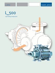
Dimensions • Abmessungen (in inches / mm)<br />
<strong>2BE3</strong> 300/320 -2<br />
9 A A A @ A<br />
, 5 A EJA<br />
5 D = BJA @<br />
, I E@ A<br />
<br />
, 5 A EJA<br />
, I E@ A<br />
" ! <br />
<br />
' ! <br />
" ' <br />
)<br />
*<br />
5 A EJA<br />
I E@ A<br />
" ! <br />
<br />
! $ & <br />
' ! #<br />
<br />
& %<br />
<br />
& $ <br />
% #<br />
& $ <br />
% #<br />
" " <br />
<br />
! <br />
<br />
! # $ <br />
' #<br />
" $ <br />
$<br />
" !<br />
! <br />
" <br />
& ! <br />
<br />
<br />
! #<br />
% <br />
$ % <br />
"<br />
+ % <br />
,<br />
-<br />
" ? A ? JE F JE = BH , I E@ A H I E@ A <br />
) I ? D K I I M = D M A EI A , 5 A EJA @ A H 5 A EJA<br />
" !<br />
! <br />
" <br />
& % <br />
" % #<br />
' <br />
! <br />
" !<br />
" <br />
" <br />
% ! $<br />
& <br />
" & <br />
" " <br />
!<br />
$ <br />
! # <br />
& <br />
& # ' % <br />
" % # <br />
& <br />
$ <br />
# &<br />
! <br />
" $<br />
$ ' <br />
" ! <br />
.<br />
<br />
A<br />
<br />
2 * - ! ! 8 ?<br />
<br />
<br />
" <br />
@<br />
<br />
" ' ! <br />
#<br />
, <br />
@ "<br />
<br />
,<br />
! ' " <br />
<br />
Type A B C D E F Connection b c e<br />
inches / mm Anschluss inches / mm<br />
<strong>2BE3</strong> 300 65.4 35.1 33.1 39.1 73.7 36.9 DIN 54.3 30.6 9.6<br />
1660 892 842 992 1873 936 1380 778 245<br />
<strong>2BE3</strong> 320 74.6 44.4 42.4 48.3 83.0 44.5 ANSI 57.2 32.0 11.0<br />
1896 1128 1078 1228 2109 1054 1454 812 279<br />
Connec- suitable for DIN EN 1092-2 (mm) suitable for ANSI B16.5 150 lbs (inches)<br />
tion geeignet für DIN EN 1092-2 (mm) geeignet für ANSI B16.5 150 lbs (inches)<br />
Anschluss DN d2 d4 D k z R1 DN d2 d4 D k z<br />
N1.0/ 1.01 Inlet flange Flansch Saugstutzen PN10 150 22 212 285 240 8 -- 6 7/8 8 ½ 11 9 ½ 8<br />
N1.1 Flange manifold Flansch Hosenrohr PN10 200 22 268 340 295 12 -- 8 7/8 10 5/8 13 ½ 11 ¾ 8<br />
N2.0/ 2.01 Discharge flange Flansch Druckstutzen PN10 150 22 212 285 240 8 -- 6 7/8 8 ½ 11 9 ½ 8<br />
N2.2 Flange liquid separator Flansch Flüssigkeitsabscheider PN10 200 22 268 340 295 12 -- 8 7/8 10 5/8 13 ½ 11 ¾ 8<br />
N3.0 Connection for<br />
operating liquid<br />
N3.2 Connection for sealing<br />
liquid to stuffing boxes<br />
(external supply only)<br />
Anschluss<br />
Betriebsflüssigkeit<br />
Anschluss Sperrflüssigkeit<br />
(nur bei externer Versorgung<br />
der Stopfbuchsen)<br />
PN16 32 M16 78 -- 100 4 1 5/8* 1 ¼ -- -- -- -- --<br />
Rp ¼ Rp ¼<br />
N4.0 Drain liquid separator Ablauf Flüssigkeitsabscheider PN10 125 18 188 250 210 8 -- 5 7/8 7 5/16 10 8 ½ 8<br />
N4.2 Flush and drain openings Spül- und Entleerungsöffnung PN16 32 M16 78 -- 100 4 1 5/8* 1 ¼ -- -- -- -- --<br />
N4.3 Connection for leakage liquid Anschluss Sickerflüssigkeit Rp ½ Rp ½<br />
N4.41 Optional connection for internal<br />
liquid supply of the shaft seal<br />
Altern. Anschlussmöglichkeit<br />
für Eigenspülung der Wellendichtung<br />
N4.6 Screw plugs for total drain Verschlussschrauben für<br />
Totalentleerung<br />
N8.7 **) Screw plugs for gauge<br />
connection<br />
Verschlussschrauben für<br />
Messanschluss<br />
Rp ½ Rp ½<br />
Rp ¼ Rp ¼<br />
Rp ½ Rp ½<br />
*) R1 = connections with counter flanges acc. to ANSI B36.10 (not represental) for welding on to pipes with outside diameter R1.<br />
R1 = Anschluss mit Gegenflansch nach ANSI B36.10 (nicht dargestellt) zum Anschweißen von Rohren mit Aussendurchmesser R1.<br />
**) Lined with Polyisoprene (F27): N8.7 not available / Polyisoprenauskleidung (F27): N8.7 nicht vorhanden.<br />
_________________________________________________________________________________________________________________________________________________________<br />
© Gardner Denver Nash Jan-2007 Page / Seite 10 / 16 Changes without prior notice<br />
<strong>Catalogue</strong> <strong>sheet</strong> <strong>2BE3</strong>/<strong>NPR2</strong> Pumps<br />
Änderungen vorbehalten<br />
Edition A4a En-De
?<br />
=<br />
><br />
!<br />
Dimensions • Abmessungen (in inches / mm)<br />
<strong>2BE3</strong> 40./42. -2<br />
9 A A A @ A<br />
, 5 A EJA<br />
5 D = BJA @<br />
, I E@ A<br />
! <br />
, 5 A EJA<br />
, I E@ A<br />
# <br />
! <br />
! " <br />
# ' "<br />
)<br />
*<br />
5 A EJA<br />
I E@ A<br />
# <br />
! <br />
" % <br />
' #<br />
<br />
& %<br />
<br />
& <br />
! <br />
& <br />
! <br />
" " <br />
<br />
! <br />
<br />
" # % <br />
$ <br />
# " <br />
! %<br />
" !<br />
! <br />
" <br />
' & <br />
# <br />
" & <br />
! % %<br />
<br />
& % <br />
# <br />
+<br />
,<br />
<br />
-<br />
" ? A ? JE F JE = BH , I E@ A H I E@ A <br />
) I ? D K I I M = D M A EI A , 5 A EJA @ A H 5 A EJA<br />
" !<br />
! <br />
" <br />
" " <br />
$ <br />
! <br />
! !<br />
" !<br />
" <br />
% <br />
& # "<br />
#<br />
$ ! <br />
! " " <br />
$ <br />
& % #<br />
" ' <br />
' <br />
" $ $ <br />
$ # $ $ <br />
<br />
! <br />
& <br />
'<br />
! <br />
" $<br />
<br />
# $ <br />
2 * - ! " 8 ><br />
.<br />
<br />
<br />
A<br />
<br />
<br />
" <br />
@<br />
<br />
, <br />
@ "<br />
<br />
,<br />
# <br />
! <br />
Type A B C D E F Connection a b c e<br />
inches / mm Anschluss inches / mm<br />
<strong>2BE3</strong> 40. 82.8 46.0 43.4 51.7 92.9 46.4 DIN 59.8 69.3 39.9 11.2<br />
2102 1169 1103 1314 2359 1179 1520 1760 1014 284<br />
<strong>2BE3</strong> 42 94.1 57.4 54.8 63.1 104.3 52.1 ANSI 63.0 72.4 41.3 12.5<br />
2391 1458 1392 1603 2648 1323 1600 1840 1048 318<br />
Connec- suitable for DIN EN 1092-2 (mm) suitable for ANSI B16.5 150 lbs (inches)<br />
tion geeignet für DIN EN 1092-2 (mm) geeignet für ANSI B16.5 150 lbs (inches)<br />
Anschluss DN d2 d4 D k z R1 DN d2 d4 D k z<br />
N1.0/ 1.01 Inlet flange Flansch Saugstutzen PN10 250 22 320 395 350 12 -- 10 1 12 ¾ 16 14 ¼ 12<br />
N1.1 Flange manifold Flansch Hosenrohr PN10 300 22 370 445 400 12 -- 12 1 15 19 17 12<br />
N2.0/ 2.01 Discharge flange Flansch Druckstutzen PN10 250 22 320 395 350 12 -- 10 1 12 ¾ 16 14 ¼ 12<br />
N2.2 Flange liquid separator Flansch Flüssigkeitsabscheider PN10 300 22 370 445 400 12 -- 12 1 15 19 17 12<br />
N3.0 Connection for<br />
operating liquid<br />
N3.2 Connection for sealing<br />
liquid to stuffing boxes<br />
(external supply only)<br />
Anschluss<br />
Betriebsflüssigkeit<br />
Anschluss Sperrflüssigkeit<br />
(nur bei externer Versorgung<br />
der Stopfbuchsen)<br />
PN16 50 M16 102 -- 125 4 2 3/8* 2 -- -- -- -- --<br />
Rp ¼ Rp ¼<br />
N4.0 Drain liquid separator Ablauf Flüssigkeitsabscheider PN10 150 22 212 285 240 8 -- 6 7/8 8 ½ 11 9 ½ 8<br />
N4.2 Flush and drain openings Spül- und Entleerungsöffnung PN16 50 M16 102 -- 125 4 2 3/8* 2 -- -- -- -- --<br />
N4.3 Connection for leakage liquid Anschluss Sickerflüssigkeit Rp ¾ Rp ¾<br />
N4.41 Optional connection for internal<br />
liquid supply of the shaft seal<br />
Altern. Anschlussmöglichkeit<br />
für Eigenspülung der Wellendichtung<br />
N4.6 Screw plugs for total drain Verschlussschrauben für<br />
Totalentleerung<br />
N8.7 **) Screw plugs for gauge<br />
connection<br />
Verschlussschrauben für<br />
Messanschluss<br />
Rp ½ Rp ½<br />
Rp ½ Rp ½<br />
Rp ½ Rp ½<br />
*) R1 = connections with counter flanges acc. to ANSI B36.10 (not represental) for welding on to pipes with outside diameter R1.<br />
R1 = Anschluss mit Gegenflansch nach ANSI B36.10 (nicht dargestellt) zum Anschweißen von Rohren mit Aussendurchmesser R1.<br />
**) Lined with Polyisoprene (F27): N8.7 not available / Polyisoprenauskleidung (F27): N8.7 nicht vorhanden.<br />
_________________________________________________________________________________________________________________________________________________________<br />
© Gardner Denver Nash Jan-2007 Page / Seite 11 / 16 Changes without prior notice<br />
<strong>Catalogue</strong> <strong>sheet</strong> <strong>2BE3</strong>/<strong>NPR2</strong> Pumps<br />
Änderungen vorbehalten<br />
Edition A4a En-De
?<br />
=<br />
><br />
%<br />
Dimensions • Abmessungen (in inches / mm)<br />
<strong>2BE3</strong> 50./52. -2<br />
9 A A A @ A<br />
, 5 A EJA<br />
5 D = BJA @<br />
, I E@ A<br />
$ <br />
" <br />
, 5 A EJA<br />
, I E@ A<br />
$ ! <br />
$ <br />
$ # <br />
$ %<br />
)<br />
*<br />
5 A EJA<br />
I E@ A<br />
$ ! <br />
$ <br />
# & % <br />
" ' <br />
<br />
& %<br />
<br />
# <br />
! & #<br />
# <br />
! & #<br />
" " <br />
<br />
! <br />
<br />
# % <br />
" # <br />
$ % <br />
$ '<br />
" !<br />
! <br />
" <br />
& <br />
! <br />
$ <br />
" <br />
<br />
' & <br />
# <br />
+ # <br />
,<br />
-<br />
" ? A ? JE F JE = BH , I E@ A H I E@ A <br />
) I ? D K I I M = D M A EI A , 5 A EJA @ A H 5 A EJA<br />
" !<br />
! <br />
" <br />
! # <br />
% % #<br />
% & <br />
" # <br />
" !<br />
" <br />
% <br />
' & "<br />
# <br />
$ ' <br />
" " <br />
% #<br />
<br />
# ! ' <br />
! % <br />
' # ! <br />
% # % ' <br />
" <br />
! #<br />
& ' <br />
! <br />
" $<br />
% # <br />
$ ' &<br />
2 * - ! # 8 ><br />
.<br />
<br />
<br />
A<br />
<br />
<br />
" <br />
@<br />
<br />
, <br />
@ "<br />
<br />
,<br />
$ ! ! <br />
# & <br />
Type A B C D E F Connection a b c e<br />
inches / mm Anschluss inches / mm<br />
<strong>2BE3</strong> 50. 102.5 61.7 58.7 67.8 114.7 57.3 DIN 72.8 86.0 48.5 14.4<br />
2603 1568 1490 1723 2913 1456 1850 2185 1232 367<br />
<strong>2BE3</strong> 52. 112.3 71.6 68.5 77.7 124.5 62.2 ANSI 77.0 90.2 50.3 16.0<br />
2853 1818 1740 1973 3163 1581 1955 2290 1278 407<br />
Connec- suitable for DIN EN 1092-2 (mm) suitable for ANSI B16.5 150 lbs (inches)<br />
tion geeignet für DIN EN 1092-2 (mm) geeignet für ANSI B16.5 150 lbs (inches)<br />
Anschluss DN d2 d4 D k z R1 DN d2 d4 D k z<br />
N1.0/ 1.01 Inlet flange Flansch Saugstutzen PN10 300 22 370 445 400 12 -- 12 1 15 19 17 12<br />
N1.1 Flange manifold Flansch Hosenrohr PN10 350 22 430 505 460 16 -- 14 1 1/8 16 ¼ 21 18 ¾ 12<br />
N2.0/ 2.01 Discharge flange Flansch Druckstutzen PN10 300 22 370 445 400 12 -- 12 1 15 19 17 12<br />
N2.2 Flange liquid separator Flansch Flüssigkeitsabscheider PN10 350 22 430 505 460 16 -- 14 1 1/8 16 ¼ 21 18 ¾ 12<br />
N3.0 Connection for<br />
operating liquid<br />
N3.2 Connection for sealing<br />
liquid to stuffing boxes<br />
(external supply only)<br />
Anschluss<br />
Betriebsflüssigkeit<br />
Anschluss Sperrflüssigkeit<br />
(nur bei externer Versorgung<br />
der Stopfbuchsen)<br />
PN16 50 M16 102 -- 125 4 2 3/8* 2 -- -- -- -- --<br />
Rp ¼ Rp ¼<br />
N4.0 Drain liquid separator Ablauf Flüssigkeitsabscheider PN10 200 22 268 340 295 8 -- 8 7/8 10 5/8 13 ½ 11 ¾ 8<br />
N4.2 Flush and drain openings Spül- und Entleerungsöffnung PN16 50 M16 102 -- 125 4 2 3/8* 2 -- -- -- -- --<br />
N4.3 Connection for leakage liquid Anschluss Sickerflüssigkeit Rp ¾ Rp ¾<br />
N4.41 Optional connection for internal<br />
liquid supply of the shaft seal<br />
Altern. Anschlussmöglichkeit<br />
für Eigenspülung der Wellendichtung<br />
N4.6 Screw plugs for total drain Verschlussschrauben für<br />
Totalentleerung<br />
N8.7 **) Screw plugs for gauge<br />
connection<br />
Verschlussschrauben für<br />
Messanschluss<br />
Rp ½ Rp ½<br />
Rp ½ Rp ½<br />
Rp ½ Rp ½<br />
*) R1 = connections with counter flanges acc. to ANSI B36.10 (not represental) for welding on to pipes with outside diameter R1.<br />
R1 = Anschluss mit Gegenflansch nach ANSI B36.10 (nicht dargestellt) zum Anschweißen von Rohren mit Aussendurchmesser R1.<br />
**) Lined with Polyisoprene (F27): N8.7 not available / Polyisoprenauskleidung (F27): N8.7 nicht vorhanden.<br />
_________________________________________________________________________________________________________________________________________________________<br />
© Gardner Denver Nash Jan-2007 Page / Seite 12 / 16 Changes without prior notice<br />
<strong>Catalogue</strong> <strong>sheet</strong> <strong>2BE3</strong>/<strong>NPR2</strong> Pumps<br />
Änderungen vorbehalten<br />
Edition A4a En-De
?<br />
=<br />
><br />
Dimensions • Abmessungen (in inches / mm)<br />
<strong>2BE3</strong> 60./62. -2<br />
9 A A A @ A<br />
, 5 A EJA<br />
5 D = BJA @<br />
, I E@ A<br />
& <br />
" #<br />
, 5 A EJA<br />
, I E@ A<br />
% <br />
& <br />
# $ <br />
$ # <br />
)<br />
*<br />
5 A EJA<br />
I E@ A<br />
% <br />
& <br />
$ ' ! <br />
% $ <br />
<br />
& %<br />
<br />
% <br />
" ! #<br />
% <br />
" ! #<br />
" " <br />
<br />
! <br />
<br />
$ % % <br />
% <br />
% # <br />
' <br />
" !<br />
! <br />
" <br />
& <br />
! <br />
# % <br />
! ' &<br />
! & <br />
# &<br />
+ ! <br />
,<br />
-<br />
" ? A ? JE F JE = BH , I E@ A H I E@ A <br />
) I ? D K I I M = D M A EI A , 5 A EJA @ A H 5 A EJA<br />
" !<br />
! <br />
" <br />
! # " <br />
' <br />
<br />
# ! '<br />
" !<br />
" <br />
' <br />
& <br />
" &<br />
! <br />
% ' <br />
# <br />
<br />
! <br />
$ ! & <br />
$ <br />
! " " ! $ <br />
& % # ' #<br />
& <br />
" #<br />
' & <br />
" '<br />
! <br />
" $<br />
! ' <br />
& '<br />
2 * - ! $ 8 ><br />
.<br />
<br />
<br />
A<br />
<br />
<br />
" <br />
@<br />
<br />
, <br />
@ "<br />
<br />
,<br />
% ! <br />
& ! <br />
Type A B C D E F Connection a b c e<br />
inches / mm Anschluss inches / mm<br />
<strong>2BE3</strong> 60. 111.7 72.6 68.8 80.4 123.8 61.9 DIN 85.4 100.8 59.2 14.4<br />
2837 1843 1747 2043 3144 1572 2170 2560 1503 367<br />
<strong>2BE3</strong> 62. 123.3 84.2 80.4 92.0 135.4 67.7 ANSI 89.9 104.3 61.5 16.0<br />
3132 2138 2042 2338 3439 1719 2284 2675 1563 407<br />
Connec- suitable for DIN EN 1092-2 (mm) suitable for ANSI B16.5 150 lbs (inches)<br />
tion geeignet für DIN EN 1092-2 (mm) geeignet für ANSI B16.5 150 lbs (inches)<br />
Anschluss DN d2 d4 D k z R1 DN d2 d4 D k z<br />
N1.0/ 1.01 Inlet flange Flansch Saugstutzen PN10 350 22 430 505 460 16 -- 14 1 1/8 16 ¼ 21 18 ¾ 12<br />
N1.1 Flange manifold Flansch Hosenrohr PN10 400 26 482 565 515 16 -- 16 1 1/8 18 ½ 23 ½ 21 ¼ 16<br />
N2.0/ 2.01 Discharge flange Flansch Druckstutzen PN10 350 22 430 505 460 16 -- 14 1 1/8 16 ¼ 21 18 ¾ 12<br />
N2.2 Flange liquid separator Flansch Flüssigkeitsabscheider PN10 400 26 482 565 515 16 -- 16 1 1/8 18 ½ 23 ½ 21 ¼ 16<br />
N3.0 Connection for<br />
operating liquid<br />
N3.2 Connection for sealing<br />
liquid to stuffing boxes<br />
(external supply only)<br />
Anschluss<br />
Betriebsflüssigkeit<br />
Anschluss Sperrflüssigkeit<br />
(nur bei externer Versorgung<br />
der Stopfbuchsen)<br />
PN6 80 M16 128 -- 150 4 3 ½ * 3 -- -- -- -- --<br />
Rp ½ Rp ½<br />
N4.0 Drain liquid separator Ablauf Flüssigkeitsabscheider PN10 200 22 268 340 295 8 -- 8 7/8 10 5/8 13 ½ 11 ¾ 8<br />
N4.2 Flush and drain openings Spül- und Entleerungsöffnung PN6 80 M16 128 -- 150 4 3 ½ * 3 -- -- -- -- --<br />
N4.3 Connection for leakage liquid Anschluss Sickerflüssigkeit Rp ¾ Rp ¾<br />
N4.41 Optional connection for internal<br />
liquid supply of the shaft seal<br />
Altern. Anschlussmöglichkeit<br />
für Eigenspülung der Wellendichtung<br />
N4.6 Screw plugs for total drain Verschlussschrauben für<br />
Totalentleerung<br />
N8.7 **) Screw plugs for gauge<br />
connection<br />
Verschlussschrauben für<br />
Messanschluss<br />
Rp ½ Rp ½<br />
Rp ½ Rp ½<br />
Rp ½ Rp ½<br />
*) R1 = connections with counter flanges acc. to ANSI B36.10 (not represental) for welding on to pipes with outside diameter R1.<br />
R1 = Anschluss mit Gegenflansch nach ANSI B36.10 (nicht dargestellt) zum Anschweißen von Rohren mit Aussendurchmesser R1.<br />
**) Lined with Polyisoprene (F27): N8.7 not available / Polyisoprenauskleidung (F27): N8.7 nicht vorhanden.<br />
_________________________________________________________________________________________________________________________________________________________<br />
© Gardner Denver Nash Jan-2007 Page / Seite 13 / 16 Changes without prior notice<br />
<strong>Catalogue</strong> <strong>sheet</strong> <strong>2BE3</strong>/<strong>NPR2</strong> Pumps<br />
Änderungen vorbehalten<br />
Edition A4a En-De
?<br />
=<br />
><br />
Dimensions • Abmessungen (in inches / mm)<br />
<strong>2BE3</strong> 67. -2<br />
9 A A A @ A<br />
, 5 A EJA<br />
5 D = BJA @<br />
, I E@ A<br />
& <br />
" #<br />
, 5 A EJA<br />
, I E@ A<br />
% ' <br />
<br />
& ' <br />
% ! !<br />
! ! " <br />
! ! & '<br />
& ' & <br />
& <br />
5 A EJA<br />
I E@ A<br />
% ' <br />
<br />
% " & <br />
' <br />
<br />
& %<br />
<br />
& <br />
" $ <br />
& <br />
" $ <br />
" " <br />
<br />
! <br />
<br />
% ! <br />
& # #<br />
& ! <br />
<br />
" !<br />
! <br />
" <br />
! & <br />
! # <br />
$ % <br />
" !<br />
! & <br />
# &<br />
& $ $ <br />
<br />
! <br />
' % $ <br />
" & <br />
" % $ <br />
! % " &<br />
" ? A ? JE F JE = BH , I E@ A H I E@ A <br />
) I ? D K I I M = D M A EI A , 5 A EJA @ A H 5 A EJA<br />
" !<br />
! <br />
" <br />
! & " <br />
' % #<br />
% <br />
# % $<br />
" !<br />
" <br />
' <br />
$ <br />
" &<br />
! <br />
% ' <br />
# # <br />
<br />
" <br />
$ & # <br />
% " <br />
! $ & ! & $ <br />
' ! #<br />
' & <br />
! <br />
& <br />
" #<br />
! <br />
" $<br />
$ <br />
! " # <br />
& % %<br />
2 * - ! $ % 8 ><br />
% ! % <br />
& % !<br />
<br />
<br />
A<br />
<br />
<br />
" <br />
@<br />
<br />
, <br />
@ "<br />
<br />
,<br />
% % <br />
' $ <br />
Connection a b c e a b c e<br />
Anschluss mm inches<br />
DIN 2308 2990 1734 449 90.9 108.3 64.6 14.4<br />
ANSI 2436 3080 1755 483 95.9 113.4 67.0 16.0<br />
Connec- suitable for DIN EN 1092-2 (mm) suitable for ANSI B16.5 150 lbs (inches)<br />
tion geeignet für DIN EN 1092-2 (mm) geeignet für ANSI B16.5 150 lbs (inches)<br />
Anschluss DN d2 d4 D k z R1 DN d2 d4 D k z<br />
N1.0/ 1.01 Inlet flange Flansch Saugstutzen PN10 350 22 430 505 460 16 -- 14 1 1/8 16 ¼ 21 18 ¾ 12<br />
N1.1 Flange manifold Flansch Hosenrohr PN10 500 26 585 670 620 20 -- 20 1 ¼ 23 27 ½ 25 20<br />
N2.0/ 2.01 Discharge flange Flansch Druckstutzen PN10 350 22 430 505 460 16 -- 14 1 1/8 16 ¼ 21 18 ¾ 12<br />
N2.2 Flange liquid separator Flansch Flüssigkeitsabscheider PN10 500 26 585 670 620 20 -- 20 1 1/4 23 27 ½ 25 20<br />
N3.0 Connection for<br />
operating liquid<br />
N3.2 Connection for sealing<br />
liquid to stuffing boxes<br />
(external supply only)<br />
Anschluss<br />
Betriebsflüssigkeit<br />
Anschluss Sperrflüssigkeit<br />
(nur bei externer Versorgung<br />
der Stopfbuchsen)<br />
PN6 80 M16 128 -- 150 4 3 ½ * 3 -- -- -- -- --<br />
Rp ½ Rp ½<br />
N4.0 Drain liquid separator Ablauf Flüssigkeitsabscheider PN10 200 22 268 340 295 8 -- 8 7/8 10 5/8 13 ½ 11 ¾ 8<br />
N4.2 Flush and drain openings Spül- und Entleerungsöffnung PN6 80 M16 128 -- 150 4 3 ½ * 3 -- -- -- -- --<br />
N4.3 Connection for leakage liquid Anschluss Sickerflüssigkeit Rp ¾ Rp ¾<br />
N4.41 Optional connection for internal<br />
liquid supply of the shaft seal<br />
Altern. Anschlussmöglichkeit<br />
für Eigenspülung der Wellendichtung<br />
N4.6 Screw plugs for total drain Verschlussschrauben für<br />
Totalentleerung<br />
N8.7 **) Screw plugs for gauge<br />
connection<br />
Verschlussschrauben für<br />
Messanschluss<br />
Rp ½ Rp ½<br />
Rp ½ Rp ½<br />
Rp ½ Rp ½<br />
*) R1 = connections with counter flanges acc. to ANSI B36.10 (not represental) for welding on to pipes with outside diameter R1.<br />
R1 = Anschluss mit Gegenflansch nach ANSI B36.10 (nicht dargestellt) zum Anschweißen von Rohren mit Aussendurchmesser R1.<br />
**) Lined with Polyisoprene (F27): N8.7 not available / Polyisoprenauskleidung (F27): N8.7 nicht vorhanden.<br />
_________________________________________________________________________________________________________________________________________________________<br />
© Gardner Denver Nash Jan-2007 Page / Seite 14 / 16 Changes without prior notice<br />
<strong>Catalogue</strong> <strong>sheet</strong> <strong>2BE3</strong>/<strong>NPR2</strong> Pumps<br />
Änderungen vorbehalten<br />
Edition A4a En-De
?<br />
=<br />
><br />
Dimensions • Abmessungen (in inches / mm)<br />
<strong>2BE3</strong> 72. -2<br />
9 A A A @ A<br />
, 5 A EJA<br />
5 D = BJA @<br />
, I E@ A<br />
& <br />
" #<br />
, 5 A EJA<br />
, I E@ A<br />
% ' <br />
<br />
& " <br />
%<br />
" <br />
! # & %<br />
' & " <br />
# <br />
5 A EJA<br />
I E@ A<br />
% ' <br />
<br />
% ' ' <br />
! <br />
<br />
& %<br />
<br />
' ! <br />
" ' <br />
' ! <br />
" ' <br />
" " <br />
<br />
! <br />
<br />
% & <br />
' & #<br />
& ! <br />
<br />
" !<br />
! <br />
" <br />
! & <br />
! # <br />
$ & <br />
" %<br />
! ! " <br />
# &<br />
' " <br />
! ' <br />
! " <br />
% # <br />
% ! <br />
# # " <br />
! ' " $<br />
" ? A ? JE F JE = BH , I E@ A H I E@ A <br />
) I ? D K I I M = D M A EI A , 5 A EJA @ A H 5 A EJA<br />
" !<br />
! <br />
" <br />
" % <br />
$ <br />
$ <br />
$ $ !<br />
" !<br />
" <br />
' <br />
! " <br />
" &<br />
! " <br />
% ' <br />
$ ! <br />
<br />
$ <br />
% " & <br />
' <br />
" " " <br />
# % <br />
% <br />
& <br />
" #<br />
! <br />
" $<br />
% !<br />
! % # <br />
' #<br />
2 * - ! % 8 ?<br />
% % $ <br />
' %<br />
<br />
<br />
A<br />
<br />
<br />
" <br />
@<br />
<br />
, <br />
@ "<br />
<br />
,<br />
& " ! <br />
" <br />
Connection a b c e a b c e<br />
Anschluss mm inches<br />
DIN 2308 2990 1734 449 90.9 108.3 64.6 14.4<br />
ANSI 2436 3080 1755 483 95.9 113.4 67.0 16.0<br />
Connec- suitable for DIN EN 1092-2 (mm) suitable for ANSI B16.5 150 lbs (inches)<br />
tion geeignet für DIN EN 1092-2 (mm) geeignet für ANSI B16.5 150 lbs (inches)<br />
Anschluss DN d2 d4 D k z R1 DN d2 d4 D k z<br />
N1.0/ 1.01 Inlet flange Flansch Saugstutzen PN10 400 26 482 565 515 16 -- 16 1 1/8 18 ½ 23 ½ 21 ¼ 16<br />
N1.1 Flange manifold Flansch Hosenrohr PN10 500 26 585 670 620 20 -- 20 1 ¼ 23 27 ½ 25 20<br />
N2.0/ 2.01 Discharge flange Flansch Druckstutzen PN10 400 26 482 565 515 16 -- 16 1 1/8 18 ½ 23 ½ 21 ¼ 16<br />
N2.2 Flange liquid separator Flansch Flüssigkeitsabscheider PN10 500 26 585 670 620 20 -- 20 1 ¼ 23 27 ½ 25 20<br />
N3.0 Connection for<br />
operating liquid<br />
N3.2 Connection for sealing<br />
liquid to stuffing boxes<br />
(external supply only)<br />
Anschluss<br />
Betriebsflüssigkeit<br />
Anschluss Sperrflüssigkeit<br />
(nur bei externer Versorgung<br />
der Stopfbuchsen)<br />
PN6 80 M16 128 -- 150 4 3 ½ * 3 -- -- -- -- --<br />
Rp ½ Rp ½<br />
N4.0 Drain liquid separator Ablauf Flüssigkeitsabscheider PN10 250 22 320 395 350 12 -- 10 1 12 ¾ 16 14 ¼ 12<br />
N4.2 Flush and drain openings Spül- und Entleerungsöffnung PN6 80 M16 128 -- 150 4 3 ½ * 3 -- -- -- -- --<br />
N4.3 Connection for leakage liquid Anschluss Sickerflüssigkeit Rp ¾ Rp ¾<br />
N4.41 Optional connection for internal<br />
liquid supply of the shaft seal<br />
Altern. Anschlussmöglichkeit<br />
für Eigenspülung der Wellendichtung<br />
N4.6 Screw plugs for total drain Verschlussschrauben für<br />
Totalentleerung<br />
N8.7 **) Screw plugs for gauge<br />
connection<br />
Verschlussschrauben für<br />
Messanschluss<br />
Rp ½ Rp ½<br />
Rp ½ Rp ½<br />
Rp ½ Rp ½<br />
*) R1 = connections with counter flanges acc. to ANSI B36.10 (not represental) for welding on to pipes with outside diameter R1.<br />
R1 = Anschluss mit Gegenflansch nach ANSI B36.10 (nicht dargestellt) zum Anschweißen von Rohren mit Aussendurchmesser R1.<br />
**) Lined with Polyisoprene (F27): N8.7 not available / Polyisoprenauskleidung (F27): N8.7 nicht vorhanden.<br />
_________________________________________________________________________________________________________________________________________________________<br />
© Gardner Denver Nash Jan-2007 Page / Seite 15 / 16 Changes without prior notice<br />
<strong>Catalogue</strong> <strong>sheet</strong> <strong>2BE3</strong>/<strong>NPR2</strong> Pumps<br />
Änderungen vorbehalten<br />
Edition A4a En-De
Dimensions • Abmessungen (in mm / inches)<br />
<strong>NPR2</strong> 620<br />
PL-6045b<br />
Connec- suitable for DIN EN 1092-2 (mm) suitable for ANSI B16.5 150 lbs (inches)<br />
tion geeignet für DIN EN 1092-2 (mm) geeignet für ANSI B16.5 150 lbs (inches)<br />
Anschluss DN d2 d4 D k t z1 z2 R1 DN d2 d4 D k t z1 z2<br />
N1.0 Inlet flange Flansch Saugstutzen PN10 400 26 482 596 515 38 10 6 -- 16 1 1/8 18 ½ 23 ½ 21 ¼ 1 ½ 10 6<br />
N2.0 Discharge flange Flansch Druckstutzen PN10 350 22 430 534 460 38 10 6 -- 14 1 1/8 16 ¼ 21 18 ¾ 1 ½ 8 4<br />
N2.01 Discharge flange Flansch Druckstutzen PN10 350 22 430 534 460 38 7 9 -- 14 1 1/8 16 ¼ 21 18 ¾ 1 ½ 6 6<br />
N3.0 Connection for<br />
operating liquid<br />
N3.2 Connection for<br />
sealing liquid to<br />
stuffing boxes<br />
(external supply only)<br />
N3.9 Connection for<br />
spray nozzle<br />
N4.3 Connection for<br />
leakage liquid<br />
N4.61 Screw plugs for<br />
total drain<br />
N4.62 Screw plugs for<br />
total drain<br />
N8.6 Screw plugs for<br />
casing inspection<br />
N8.7 Screw plugs for<br />
gauge connection<br />
N8.8 Screw plugs for<br />
lobe purge<br />
Anschluss<br />
Betriebsflüssigkeit<br />
Anschluss Sperrflüssigkeit<br />
(nur bei externer<br />
Versorgung der Stopfbuchsen)<br />
Anschluss für<br />
Einspritzdüse<br />
Anschluss Sickerflüssigkeit<br />
Verschlussschrauben<br />
für Totalentleerung<br />
Verschlussschrauben<br />
für Totalentleerung<br />
Verschlussschrauben<br />
für Gehäuseinspektion<br />
Verschlussschrauben<br />
für Messanschluss<br />
Verschlussschrauben<br />
für interne Gehäusespülung<br />
Rp 3 Rp 3<br />
Rp 3/8 Rp 3/8<br />
Rp 2 Rp 2<br />
Rp 1 Rp 1<br />
Rp ¾ Rp ¾<br />
Rp 2 Rp 2<br />
Rp ½ Rp ½<br />
Rp ¾ Rp ¾<br />
Rp ¾ Rp ¾<br />
Gardner Denver Nash LLC Gardner Denver Nash<br />
Deutschland GmbH www.GardnerDenverNash.com x:\SG211.8\<strong>2BE3</strong>_<strong>NPR2</strong>_Pump_Catalog_A4a_EnDe_Jan-07.doc (18.01.2007)<br />
9 Trefoil Drive<br />
Katzwanger Strasse 150<br />
The technical data are subject to change. All Illustrations are for reference only.<br />
Änderungen, insbesondere der angegebenen Werte, vorbehalten.<br />
Trumbull, CT 06611 90461 Nuremberg<br />
Alle Abbildungen sind unverbindlich.<br />
USA<br />
Germany<br />
nash@gardnerdenver.com<br />
phone: +1 800 553 NASH phone: +49 911 1454-0 info@de.gardnerdenver.com<br />
_________________________________________________________________________________________________________________________________________________________<br />
© Gardner Denver Nash Jan-2007 Page / Seite 16 / 16 Changes without prior notice<br />
<strong>Catalogue</strong> <strong>sheet</strong> <strong>2BE3</strong>/<strong>NPR2</strong> Pumps<br />
Änderungen vorbehalten<br />
Edition A4a En-De