KESSEL-Pumpstation Aqualift® S LW 600/LW 1000 ... - Kessel Design
KESSEL-Pumpstation Aqualift® S LW 600/LW 1000 ... - Kessel Design
KESSEL-Pumpstation Aqualift® S LW 600/LW 1000 ... - Kessel Design

Sie wollen auch ein ePaper? Erhöhen Sie die Reichweite Ihrer Titel.
YUMPU macht aus Druck-PDFs automatisch weboptimierte ePaper, die Google liebt.
4. Installation and assembly<br />
CAUTION:<br />
- Hazard through heavy weights<br />
- The pre-assembled bottom part of the chamber, the<br />
chamber cover and the pump(s). The parts may only be<br />
lifted and/or assembled using suitable equipment and<br />
exercising appropriate caution.<br />
- - Danger of slipping<br />
- There is a danger of slipping during entry into the inspection<br />
chamber. For this reason, a second person must<br />
always be available to monitor the entry into the chamber<br />
from the outside.<br />
- Danger of tilting<br />
- Before the excavation pit is backfilled, there is a risk of<br />
the chamber tilting. For this reason, no-one may enter<br />
the chamber until the excavation pit has been completely<br />
backfilled.<br />
4.1 Installation of the chamber system<br />
The foundation soil must be levelled horizontally with 30<br />
cm gravel and compacted. 10 cm gritting material must be<br />
added to this. Now the chamber is set down on its whole<br />
surface. Observe the position of the inlet, ventilation and<br />
cable conduit pipes as well as the position of the pressure<br />
pipe (see section 4.2).<br />
The chamber system must be filled with gravel (type G1<br />
according to ATV-A127) in 30 cm steps and compacted.<br />
When the connection heights are reached, pipes must be<br />
connected accordingly (see section “Connecting the<br />
pipes”).<br />
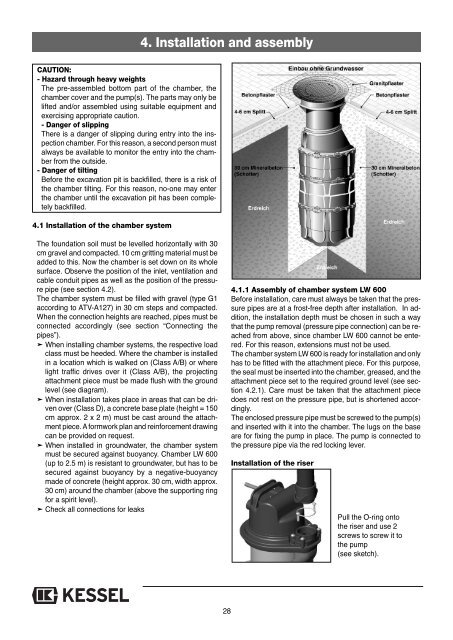
➤ When installing chamber systems, the respective load<br />
class must be heeded. Where the chamber is installed<br />
in a location which is walked on (Class A/B) or where<br />
light traffic drives over it (Class A/B), the projecting<br />
attachment piece must be made flush with the ground<br />
level (see diagram).<br />
➤ When installation takes place in areas that can be driven<br />
over (Class D), a concrete base plate (height = 150<br />
cm approx. 2 x 2 m) must be cast around the attachment<br />
piece. A formwork plan and reinforcement drawing<br />
can be provided on request.<br />
➤ When installed in groundwater, the chamber system<br />
must be secured against buoyancy. Chamber <strong>LW</strong> <strong>600</strong><br />
(up to 2.5 m) is resistant to groundwater, but has to be<br />
secured against buoyancy by a negative-buoyancy<br />
made of concrete (height approx. 30 cm, width approx.<br />
30 cm) around the chamber (above the supporting ring<br />
for a spirit level).<br />
➤ Check all connections for leaks<br />
4.1.1 Assembly of chamber system <strong>LW</strong> <strong>600</strong><br />
Before installation, care must always be taken that the pressure<br />
pipes are at a frost-free depth after installation. In addition,<br />
the installation depth must be chosen in such a way<br />
that the pump removal (pressure pipe connection) can be reached<br />
from above, since chamber <strong>LW</strong> <strong>600</strong> cannot be entered.<br />
For this reason, extensions must not be used.<br />
The chamber system <strong>LW</strong> <strong>600</strong> is ready for installation and only<br />
has to be fitted with the attachment piece. For this purpose,<br />
the seal must be inserted into the chamber, greased, and the<br />
attachment piece set to the required ground level (see section<br />
4.2.1). Care must be taken that the attachment piece<br />
does not rest on the pressure pipe, but is shortened accordingly.<br />
The enclosed pressure pipe must be screwed to the pump(s)<br />
and inserted with it into the chamber. The lugs on the base<br />
are for fixing the pump in place. The pump is connected to<br />
the pressure pipe via the red locking lever.<br />
Installation of the riser<br />
Pull the O-ring onto<br />
the riser and use 2<br />
screws to screw it to<br />
the pump<br />
(see sketch).<br />
28