KESSEL-Pumpstation Aqualift® S LW 600/LW 1000 ... - Kessel Design
KESSEL-Pumpstation Aqualift® S LW 600/LW 1000 ... - Kessel Design
KESSEL-Pumpstation Aqualift® S LW 600/LW 1000 ... - Kessel Design

Erfolgreiche ePaper selbst erstellen
Machen Sie aus Ihren PDF Publikationen ein blätterbares Flipbook mit unserer einzigartigen Google optimierten e-Paper Software.
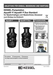
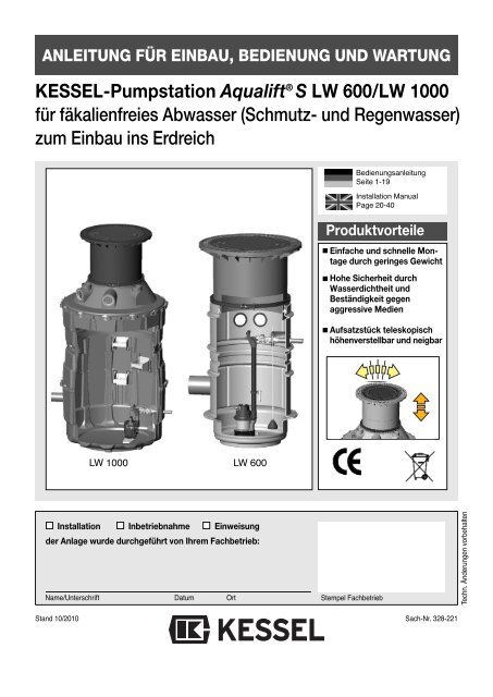
ANLEITUNG FÜR EINBAU, BEDIENUNG UND WARTUNG<br />
<strong>KESSEL</strong>-<strong>Pumpstation</strong> Aqualift ® S <strong>LW</strong> <strong>600</strong>/<strong>LW</strong> <strong>1000</strong><br />
für fäkalienfreies Abwasser (Schmutz- und Regenwasser)<br />
zum Einbau ins Erdreich<br />
Bedienungsanleitung<br />
Seite 1-19<br />
Installation Manual<br />
Page 20-40<br />
Produktvorteile<br />
Einfache und schnelle Montage<br />
durch geringes Gewicht<br />
Hohe Sicherheit durch<br />
Wasserdichtheit und<br />
Beständigkeit gegen<br />
aggressive Medien<br />
Aufsatzstück teleskopisch<br />
höhenverstellbar und neigbar<br />
<strong>LW</strong> <strong>1000</strong> <strong>LW</strong> <strong>600</strong><br />
Installation Inbetriebnahme Einweisung<br />
der Anlage wurde durchgeführt von Ihrem Fachbetrieb:<br />
Name/Unterschrift Datum Ort<br />
Stand 10/2010<br />
Stempel Fachbetrieb<br />
Sach-Nr. 328-221<br />
Techn. Änderungen vorbehalten
Inhaltsverzeichnis<br />
1. Sicherheitshinweise ....................................................................................Seite 3<br />
2. Allgemeines 2.1 Einsatzbereich ............................................................Seite 5<br />
2.2 Anlagenbeschreibung .................................................Seite 5<br />
2.3 Ausführungen..............................................................Seite 6<br />
3. Technische Daten ....................................................................................Seite 8<br />
4. Einbau und Montage 4.1 Montage Schachtsystem.............................................Seite 9<br />
4.2 Anschluß der Rohrleitungen........................................Seite 11<br />
4.3 Einsetzen der Pumpe(n) .............................................Seite 12<br />
5. Inbetriebnahme 5.1 Allgemeine Hinweise...................................................Seite 13<br />
5.2 Außerbetriebnahme/Zwischenlagerung ......................Seite 13<br />
6. Inspektion und Wartung ....................................................................................Seite 14<br />
7. Gewährleistung ....................................................................................Seite 14<br />
8. Ersatzteile ....................................................................................Seite 15<br />
9. Konformitätserklärung ....................................................................................Seite 17<br />
9. Übergabeprotokoll ....................................................................................Seite 18<br />
Sehr geehrter Kunde,<br />
wir freuen uns, daß Sie sich für ein Produkt von <strong>KESSEL</strong> entschieden haben.<br />
Die gesamte Anlage wurde vor Verlassen des Werkes einer strengen Qualitätskontrolle unterzogen. Prüfen Sie bitte<br />
dennoch sofort, ob die Anlage vollständig und unbeschädigt bei Ihnen angeliefert wurde. Im Falle eines Transportschadens<br />
beachten Sie bitte die Anweisungen in Kapitel „Gewährleistungen“ dieser Anleitung.<br />
Bevor Sie die <strong>KESSEL</strong>-<strong>Pumpstation</strong> Aqualift ® -S installieren und in Betrieb nehmen, ist es - in Ihrem eigenen Interesse<br />
- unverzichtbar, daß Sie diese Einbau-, Bedienungs- und Wartungsanleitung sorgfältig lesen und befolgen.<br />
<strong>KESSEL</strong> AG
1. Sicherheitshinweise<br />
Allgemeine Sicherheitsvorkehrungen<br />
Bei Installation, Betrieb, Wartung oder Reparatur der Anlage sind die Unfallverhütungsvorschriften, die in<br />
Frage kommenden DIN- und VDE-Normen und Richtlinien sowie die Vorschriften der örtlichen Energie- und<br />
Versorgungsunternehmen zu beachten.<br />
Weiter sind auch die Sicherheitsvorschriften für den Explosionsschutz in abwassertechnischen Anlagen zu<br />
beachten. In Gefahrenzonen, z.B. <strong>Pumpstation</strong>en und Kläranlagen, die den Auflagen der Unfallversicherer<br />
der Öffentlichen Hand unterliegen, sind Geräte in explosionsgeschützter Ausführung vorzusehen. Einbau,<br />
elektrische Installation und Inbetriebnahme nur durch Fachpersonal.<br />
Personalqualifikation und -schulung<br />
Das Personal für Bedienung, Wartung, Inspektion und Montage muss die entsprechende Qualifikation für<br />
diese Arbeiten aufweisen.<br />
Verantwortungsbereich, Zuständigkeit und die Überwachung des Personals müssen durch den Betreiber<br />
genau geregelt sein. Liegen bei dem Personal nicht die notwendigen Kenntnisse vor, so ist dieses zu schulen<br />
und zu unterweisen. Dies kann, falls erforderlich, im Auftrag des Betreibers der Pumpe durch den Hersteller/Lieferer<br />
erfolgen.<br />
Weiterhin ist durch den Betreiber sicherzustellen, dass der Inhalt der Betriebsanleitung durch das Personal<br />
voll verstanden wird. Dazu hat eine dokumentierte Einweisung zu erfolgen.<br />
Gefahr durch elektrische Spannung<br />
Diese Anlage enthält elektrische Spannungen und steuert drehende, mechanische Anlagenteile. Bei Nichtbeachtung<br />
der Bedienungsanleitung können erheblicher Sachschaden, Körperverletzung oder gar tödliche<br />
Unfälle die Folge sein.<br />
Vor allen Arbeiten an der Anlage ist diese sicher vom Netz zu trennen. Hauptschalter und Sicherungen müssen<br />
abgeschaltet, d.h. spannungsfrei geschalten und gegen Wiedereinschalten gesichert werden. Sind nur<br />
Sicherungen vorhanden, sind diese auszuschalten und mit einem Hinweis zu versehen, damit dritte Personen<br />
die Hauptsicherung nicht wieder einschalten können.<br />
Für alle elektrischen Arbeiten an der Anlage gilt die VDE 0100.<br />
Die Anlage muss über eine Fehlerstrom-Schutzeinrichtung (RCD) mit einem Bemessungsfehlerstrom von<br />
nicht mehr als 30mA versorgt werden.<br />
Das Schaltgerät sowie die Schwimmer bzw. Niveausteuerung stehen unter Spannung und dürfen nicht geöffnet<br />
werden. Nur Elektrofachkräfte dürfen Arbeiten an den elektrischen Einrichtungen durchführen. Der Begriff<br />
Elektrofachkraft ist in der VDE 0105 definiert.<br />
Es ist sicherzustellen, daß sich die Elektrokabel sowie alle anderen elektrischen Anlagenteile in einem einwandfreien<br />
Zustand befinden. Bei Beschädigung darf die Anlage auf keinen Fall in Betrieb genommen werden<br />
bzw. ist umgehend abzustellen.<br />
Verbrennungsgefahr für Hände und Finger<br />
Der Antriebsmotor kann während des Betriebes eine hohe Temperatur entwickeln.<br />
Verletzungsgefahr für Hände und Finger<br />
Arbeiten an der Pumpe dürfen nur durchgeführt werden, wenn der Strom abgeschaltet ist und sich bewegende<br />
Teile nicht mehr drehen.<br />
Bei Wartungs- und Reparaturarbeiten ist auf scharfe Kanten zu achten.<br />
Rutschgefahr/Quetschen/Stoß<br />
Beim Einstieg in den Schacht besteht Rutschgefahr. Eine geeignete Einstiegshilfe muß vorhanden sein. Deshalb<br />
muß sicherheitshalber immer eine zweite Person von außen den Einstieg einer Person überwachen.<br />
3
1. Sicherheitshinweise<br />
Gefahr durch große Gewichte/ Standfestigkeit von Anlageteilen<br />
Die vormontierten Schachtunterteile wiegen je nach Ausführung ca. 40 - 60 kg, die Schachtabdeckungen<br />
50 - 90 kg sowie die Pumpen 15 kg. Die Teile dürfen nur mit entsprechender Hebevorrichtung zu<br />
zweit und mit entsprechender Vorsicht und Schutzausrüstung (z.B. Sicherheitsschuhe) angehoben bzw.<br />
montiert werden.<br />
.<br />
Gesundheitsgefahr/Persönliche Schutzausrüstung<br />
Die Abwasseranlage fördert fäkalienfreies Abwasser, welches gesundheitsgefährdende Stoffe enthalten<br />
kann. Bei allen Arbeiten an der Anlage ist darauf zu achten, daß kein direkter Kontakt zwischen dem Abwasser<br />
oder davon verschmutzten Anlagenteilen und Augen, Mund oder Haut stattfindet. Bei einem direkten<br />
Kontakt ist die betroffene Körperstelle sofort gründlich zu reinigen und ggf. zu desinfizieren.<br />
Darüberhinaus kann die Atmosphäre im Schachtsystem u.U. gesundheitsgefährdend wirken. Vor dem<br />
Einstieg ist deshalb dafür zu sorgen, daß ein ausreichender Luftaustausch stattgefunden hat bzw.<br />
während dem Einstieg eine entsprechende (Zwangs-) Entlüftung erfolgt.<br />
Wir empfehlen ein tragbares Multigaswarngerät mit optischen und akustischen Alarm.<br />
Lärmbelästigung / Schallschutz<br />
Während des Betriebes der Pumpe(n) ist mit einer Geräuschentwicklung zu rechnen, die je nach Einbausituation<br />
störend wirken kann. Sofern Anforderungen an die maximal zulässige Lautstärke gestellt<br />
werden, sind hierfür gegebenenfalls entsprechende Maßnahmen bauseits vorzusehen.<br />
Generell ist der bauliche Schallschutz nach DIN 4109 einzuhalten. Dies betrifft unter anderem die Schallentkopplung<br />
des Sammelbehälters, aber auch der kompletten Rohrinstallation (Zulauf-, Entlüftungs-, Kabelleerrohr-<br />
und Druckleitung).<br />
Einschalten/Inbetriebnahme der Pumpe<br />
Überprüfen Sie vor Einsatz die Bedingungen vor Ort. Die bestimmungsgemäße Verwendung der<br />
Pumpe ist Grundvoraussetzung für die Explosionssicherheit.<br />
• Trockenlauf oder Schlürfbetrieb sind auszuschließen!<br />
Die Maschine darf niemals trocken oder im Schlürfbetrieb laufen, Laufrad und Pumpengehäuse müssen<br />
immer bis zur Mindesteintauchtiefe überflutet sein.<br />
• Die Mindesteintauchtiefen sind einzuhalten!<br />
• Die Pumpe darf nicht benutzt werden, wenn sich Personen im Wasser aufhalten.<br />
• Die Pumpe baut einen Förderdruck/Überdruck auf.<br />
Die in dieser Betriebsanleitung enthaltenen Sicherheitshinweise, die für Einbau, Betrieb, Wartung und Instandsetzung des<br />
Aggregats beachtet werden müssen, sind mit folgenden Symbolen gekennzeichnet:<br />
Allgemeines Gefahrensymbol nach ISO 3864-B-3-1 zur Kennzeichnung von Gefährdungen für Personen.<br />
Gefahrensymbol nach ISO 3864-B-3-6 zur Warnung vor elektrischer Spannung.<br />
Achtung<br />
Dieses Wort kennzeichnet Sicherheitshinweise, deren Nichtbeachtung Gefahren für die Maschine und<br />
deren Funktion hervorrufen kann.<br />
Diese Bedienungsanleitung muß ständig an der Anlage vorhanden sein.<br />
4
2. Allgemeines<br />
2.1 Einsatzbereich<br />
Die <strong>Pumpstation</strong>en fördern die unterhalb der Kanal- und Rückstauebene<br />
anfallenden fäkalienfreien Abwässer entsprechend<br />
den Vorschriften der EN 12056 vollautomatisch in den Kanal.<br />
Sie sind grundsätzlich für häusliches Abwasser, beispielsweise<br />
in Ein- und Mehrfamilienhäusern, Gewerbebetrieben,<br />
Hotels und Restaurants, Kaufhäusern, Krankenhäusern<br />
Schulen oder Regenwasser (Drainage) einzusetzen.<br />
Wenn der Zufluß der <strong>Pumpstation</strong>en während des normalen<br />
Betriebes nicht unterbrochen werden darf, muß die Hebeanlage<br />
zusätzlich mit einer zweiten Fördereinrichtung mit<br />
gleicher Leistungsfähigkeit ausgerüstet werden, die sich –<br />
sofern erforderlich – selbsttätig einschaltet (Doppel- statt<br />
Einzel-Anlage).<br />
Die <strong>KESSEL</strong>-<strong>Pumpstation</strong> Aqualift ® S ist zum Einbau ins<br />
Erdreich außerhalb des Gebäudes vorgesehen. Die Anlagen<br />
sind für andauernde Abwassertemperaturen bis 35°C<br />
geeignet. Der Einbau innerhalb des Gebäudes ist nur zu<br />
empfehlen, wenn hierbei auf die Anforderungen an grundwasserdichte<br />
Bodenplatten berücksichtigt werden. Ausserdem<br />
ist auf eine ausreichende Deckenhöhe für die Entnahme<br />
der Pumpe zu achten.<br />
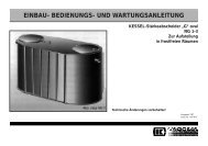
2.2 Anlagenbeschreibung<br />
Bitte beachten:<br />
Für ausreichende Be- und Entlüftung ist zu sorgen.<br />
Im Gegensatz zum Schacht <strong>LW</strong> <strong>600</strong> ist das Schachtsystem<br />
<strong>LW</strong> <strong>1000</strong> zu Wartungszwecken begehbar.<br />
<strong>LW</strong> <strong>600</strong><br />
1<br />
5<br />
7<br />
2<br />
8<br />
3<br />
6<br />
4<br />
Die <strong>KESSEL</strong>-<strong>Pumpstation</strong> Aqualift ® S als Einzel- oder Doppelanlage<br />
besteht grundsätzlich aus folgenden Bauteilen:<br />
1. ein bzw. zwei Schmutzwasserpumpen<br />
2. <strong>KESSEL</strong>-Schachtsystem <strong>LW</strong> <strong>600</strong> oder <strong>1000</strong><br />
3. Rückschlagklappe<br />
4. Druckleitungsanschlußstutzen DA 40 mm für<br />
PVC-Klebeverbindung<br />
5. Anschluß Entlüftungsleitung DN 100<br />
6. Anschluß Kabelleerrohr DN 100<br />
7. Zulaufrohr DN 100 bei Pumpentyp KTP 500<br />
DN 150 bei Pumpentyp KTP <strong>1000</strong><br />
8. Steuerungsvarianten<br />
- Schwimmer (ohne Alarmmeldung)<br />
- Tauchglocke + Alarmsonde (Tronic-/Duo-Ausführung)<br />
<strong>LW</strong> <strong>1000</strong><br />
5<br />
6<br />
2<br />
3<br />
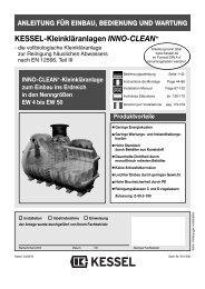
Die <strong>KESSEL</strong>-<strong>Pumpstation</strong> Aqualift ® S wird geliefert je nach<br />
Ausführung<br />
- als Einzelanlage oder als Doppelanlage<br />
- mit Pumpen verschiedener Pumpleistung<br />
- im <strong>KESSEL</strong>-Schachtsystem mit der lichten Weite von<br />
<strong>600</strong> mm oder <strong>1000</strong> mm<br />
7<br />
8<br />
Die Pumpen, die weiteren Schachtbauteile und das elektrische<br />
Schaltgerät werden als Einzelteile angeliefert. Die Pumpen<br />
werden bei Auslieferung im Aufsatzstück angeliefert. Sie<br />
sind erst nach der kompletten Montage in den Schacht einzusetzen.<br />
4<br />
5
2. Allgemeines<br />
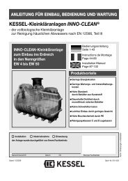
2.3. Ausführungen<br />
2.3.1 Maßzeichnung <strong>Pumpstation</strong> <strong>LW</strong> <strong>600</strong> (T1, T2, T3)<br />
Anbindungslänge<br />
Tauchglocke<br />
Stetig steigend<br />
verlegen<br />
Nicht aufgerollt/geknickt<br />
einbauen. Zulässige Luftschlauchverlegung<br />
Alarmsonde<br />
↕<br />
↕220<br />
220<br />
720<br />
1380<br />
1220<br />
Abb. zeigt Art. Nr. 825811B<br />
Gewicht: ca. 130 kg<br />
Abb. zeigt Art. Nr. 825821B<br />
Gewicht: ca. 145 kg<br />
Abb. zeigt Art. Nr. 825831B<br />
Gewicht: ca. 160 kg<br />
KTP 500<br />
1 Pumpe mit Schwimmer 1 Pumpe mit SDS-Schaltgerät 2 Pumpen mit SDS-Schaltgerät<br />
Einbautiefe T* in mm<br />
Art.Nr.<br />
Klasse A/B Klasse D<br />
Art.Nr.<br />
Klasse A/B Klasse D<br />
Art.Nr.<br />
Klasse A/B Klasse D<br />
T 1 800 - 1250 825 810 B 825 810 D 825 811 B 825 811 D 824 811 B 824 811 D<br />
T 2 1300 - 1750 825 820 B 825 820 D 825 821 B 825 821 D 824 821 B 824 821 D<br />
T 3 1800 - 2250 825 830 B 825 830 D 825 831 B 825 831 D 824 831 B 824 831 D<br />
KTP <strong>1000</strong><br />
1 Pumpe mit Schwimmer 1 Pumpe mit SDS-Schaltgerät 2 Pumpen mit SDS-Schaltgerät<br />
Einbautiefe T* in mm<br />
Art.Nr.<br />
Klasse A/B Klasse D<br />
Art.Nr.<br />
Klasse A/B Klasse D<br />
Art.Nr.<br />
Klasse A/B Klasse D<br />
T 1 800 - 1250 827 810 B 827 810 D 827 811 B 827 811 D 826 811 B 826 811 D<br />
T 2 1300 - 1750 827 820 B 827 820 D 827 821 B 827 821 D 826 821 B 826 821 D<br />
T 3 1800 - 2250 827 830 B 827 830 D 827 831 B 827 831 D 826 831 B 826 831 D<br />
* minimale Einbautiefe durch Kürzen des Aufsatzstückes<br />
Abdeckung in Klasse D: zzgl. 30 kg zu Abdeckung Klasse B<br />
6
2. Allgemeines<br />
2.3.2 Maßzeichnung <strong>Pumpstation</strong> <strong>LW</strong> <strong>1000</strong><br />
↕<br />
220<br />
Gesamtgewicht<br />
(Klasse B)<br />
T 1 185 kg<br />
T 2 215 kg<br />
T 3 238 kg<br />
T 4 268 kg<br />
T 5 288 kg<br />
T 6 308 kg<br />
T 7 328 kg<br />
Klasse D = zzgl. 30 kg<br />
KTP 500<br />
1 Pumpe mit Schwimmer 1 Pumpe mit SDS-Schaltgerät 2 Pumpen mit SDS-Schaltgerät<br />
Einbautiefe T in mm<br />
Art.Nr.<br />
Klasse A/B Klasse D<br />
Art.Nr.<br />
Klasse A/B Klasse D<br />
Art.Nr.<br />
Klasse A/B Klasse D<br />
T 1 1630 - 2130 865 810 B 865 810 D 865 811 B 865 811 D 864 811 B 864 811 D<br />
T 2 2130 - 2630 865 820 B 865 820 D 865 821 B 865 821 D 864 821 B 864 821 D<br />
T 3 2630 - 3130 865 830 B 865 830 D 865 831 B 865 831 D 864 831 B 864 831 D<br />
T 4 3130 - 3630 865 840 B 865 840 D 865 841 B 865 841 D 864 841 B 864 841 D<br />
T 5 3630 - 4130 865 850 B 865 850 D 865 851 B 865 851 D 864 851 B 864 851 D<br />
T 6 4130 - 4630 865 860 B 865 860 D 865 861 B 865 861 D 864 861 B 864 861 D<br />
T 7 4630 - 5130 865 870 B 865 870 D 865 871 B 865 871 D 864 871 B 864 871 D<br />
KTP <strong>1000</strong><br />
1 Pumpe mit Schwimmer 1 Pumpe mit SDS-Schaltgerät 2 Pumpen mit SDS-Schaltgerät<br />
Einbautiefe T in mm<br />
Art.Nr.<br />
Klasse A/B Klasse D<br />
Art.Nr.<br />
Klasse A/B Klasse D<br />
Art.Nr.<br />
Klasse A/B Klasse D<br />
T 1 1630 - 2130 867 810 B 867 810 D 867 811 B 867 811 D 866 811 B 866 811 D<br />
T 2 2130 - 2630 867 820 B 867 820 D 867 821 B 867 821 D 866 821 B 866 821 D<br />
T 3 2630 - 3130 867 830 B 867 830 D 867 831 B 867 831 D 866 831 B 866 831 D<br />
T 4 3130 - 3630 867 840 B 867 840 D 867 841 B 867 841 D 866 841 B 866 841 D<br />
T 5 3630 - 4130 867 850 B 867 850 D 867 851 B 867 851 D 866 851 B 866 851 D<br />
T 6 4130 - 4630 867 860 B 867 860 D 867 861 B 867 861 D 866 861 B 866 861 D<br />
T 7 4630 - 5130 867 870 B 867 870 D 867 871 B 867 871 D 866 871 B 866 871 D<br />
7
3. Technische Daten<br />
Anbindungslängen Tauchglocke<br />
Einbauhöhe T1:220 mm<br />
Einbauhöhe T2:720 mm<br />
Einbauhöhe T3:1220 mm<br />
Stromart<br />
Spannung<br />
Strom<br />
Motorleistung P1/P2<br />
Drehzahl<br />
Motorschutz<br />
Betriebsart<br />
Leistungsdiagramm<br />
11<br />
10<br />
9<br />
8<br />
7<br />
6<br />
5<br />
4<br />
3<br />
2<br />
1<br />
0<br />
0<br />
KTP 500 KTP <strong>1000</strong><br />
Wechselstrom<br />
230 V<br />
2,12 A<br />
480 W / 320 W<br />
2800 min -1<br />
in Motor eingebaut<br />
S1<br />
KTP 500<br />
1 2 3 4 5 6 7 8 9 10<br />
Fördermenge Q (m³/h)<br />
0 0,5 1 1,5 2 2,5<br />
Fördermenge Q (l/s)<br />
Wechselstrom<br />
230 V<br />
5,6 A<br />
1200 W / 750 W<br />
2800 min -1<br />
in Motor eingebaut<br />
S3 - 60%<br />
KTP <strong>1000</strong><br />
11 12<br />
3 3,5<br />
Bestimmungsgemäße Verwendung<br />
Die <strong>Pumpstation</strong> dient als Einzelanlage oder Doppelanlage<br />
vorrangig zur Entwässerung von Grundstücken und Gebäuden.<br />
Die Erfassung des Wasserstandes wird durch eine<br />
Tauchglocke (Staudruckmessung) ermöglicht.<br />
Das Betriebsmittel ist außerhalb des explosionsgefährdeten<br />
Bereiches zu errichten (Förderhöhe beachten).<br />
Einbauhinweise/Montage<br />
• Beachten Sie die jeweiligen nationalen Vorschriften und<br />
Bestimmungen<br />
• Die entsprechenden Errichterbestimmungen sind zu beachten<br />
Besondere Bedingungen für den sicheren Betrieb<br />
siehe frostfreie Tiefe Kapitel 4.1.1.<br />
Instandhaltung/Wartung<br />
• Es dürfen keine Änderungen am Gerät vorgenommen werden<br />
(z.B. darf auch nicht die Abdeckplatte entfernt und<br />
keine Versiegelungen geöffnet werden). Reparaturen sind<br />
nur durch den autorisierten <strong>KESSEL</strong>-Werkskundendienst<br />
zulässig..<br />
8
4. Einbau und Montage<br />
ACHTUNG:<br />
- Gefahr durch große Gewichte<br />
- Das vormontierte Schachtunterteil, die Schachtabdeckung<br />
sowie die Pumpe(n). Die Teile dürfen nur in geeigneter<br />
Weise mit entsprechender Vorsicht und Ausrüstung<br />
angehoben bzw. montiert werden.<br />
- - Rutschgefahr<br />
- Beim Einstieg in den Schacht besteht Rutschgefahr.<br />
Deshalb muß sicherheitshalber immer eine zweite Person<br />
von außen den Einstieg einer Person überwachen.<br />
- Gefahr des Kippens<br />
- Vor dem Verfüllen der Baugrube besteht die Gefahr, daß<br />
der Schacht kippt. Deshalb darf erst nach dem vollständigen<br />
Verfüllen der Baugrube ein Einstieg in den<br />
Schacht erfolgen.<br />
4.1 Montage Schachtsystem<br />
Der Baugrund ist mit 30 cm Schotter, verdichtet, waagrecht<br />
auszurichten. Darauf sind ca. 10 cm Split aufzutragen. Jetzt<br />
wird das Schachtsystem vollflächig aufgesetzt. Beachten Sie<br />
dabei die Lage der Zulauf, Entlüftungs, und Kabellehrrohrleitung<br />
sowie die Lage der Druckleitung (siehe Abschnitt 4.2).<br />
Das Schachtsystem ist mit Schotter (Bodengruppe G1 nach<br />
ATV-A127) in 30cm-Schritten aufzufüllen und zu verdichten.<br />
Bei Erreichen der Anschlußhöhen sind diese dementsprechend<br />
anzuschließen (vgl. Abschnitt „Anschluß der<br />
Rohrleitungen“).<br />
Beim Einbau der Schachtsysteme ist auf die jeweilige<br />
Belastungsklasse zu achten. Beim Einbau in begehbaren<br />
Flächen (Klasse A/B) und Flächen mit leichtem<br />
Fahrverkehr (Klasse A/B) ist das überstehende Aufsatzstück<br />
mit dem Bodenbelag einzurütteln (siehe Abbildung).<br />
Beim Einbau in befahrbaren Flächen (Klasse D) ist<br />
eine Trageplatte (Höhe = 150 mm ca. 2 x 2 m um das<br />
Aufsatzstück zu betonieren. Ein Schal- und Bewehrungsplan<br />
kann auf Anfrage zur Verfügung gestellt<br />
werden.<br />
Bei Einbau in Grundwasser ist das Schachtsystem<br />
gegen Auftrieb zu sichern. Der Schacht <strong>LW</strong> <strong>600</strong> (bis<br />
2,5 m) ist grundwasserbeständig, muß aber gegen<br />
Auftrieb über eine Auftriebssicherung aus Beton<br />
(Höhe ca. 30 cm, Breite ca. 30 cm) umlaufend um den<br />
Schacht (oberhalb des Auflagerings für eine Wasserwaage)<br />
gesichert werden.<br />
Alle Anschlüsse sind auf Dichtheit zu prüfen.<br />
4.1.1 Montage Schachtsystem <strong>LW</strong> <strong>600</strong><br />
Vor dem Einbau ist unbedingt darauf zu achten, dass die<br />
Druckverrohrung nach Einbau in frostsicherer Tiefe liegt.<br />
Ausserdem ist die Einbautiefe so zu wählen, daß die Pumpenentnahme<br />
(Druckrohranschluß) noch von oben erreichbar<br />
ist, da der Schacht <strong>LW</strong> <strong>600</strong> nicht als besteigbar gilt. Verlängerungsstücke<br />
dürfen deswegen nicht verwendet werden.<br />
Das Schachtsystem <strong>LW</strong> <strong>600</strong> ist einbaufertig und muss nur<br />
noch mit dem Aufsatzstück versehen werden. Dazu ist die<br />
Dichtung in den Schacht einzulegen, einzufetten und das<br />
Aufsatzstück auf das erforderliche Bodenniveau einzustellen<br />
(siehe Abschnitt 4.2.1). Es ist darauf zu achten, daß das Aufsatzstück<br />
nicht auf der Druckleitung aufliegt, sondern entsprechend<br />
gekürzt wird.<br />
Das beiliegende Druckrohr ist auf die Pumpe(n) aufzuschrauben<br />
und zusammen in den Schacht einzusetzen. Die<br />
am Boden befindlichen Nasen dienen zur Fixierung der<br />
Pumpe. Über den roten Verriegelungshebel wir die Pumpe<br />
an der Druckleitung angeschlossen.<br />
Montage Steigleitung<br />
O-Ring auf Steigleitung<br />
aufziehen<br />
und mit 2 Schrauben<br />
an Pumpe festschrauben<br />
(siehe Skizze).<br />
9
4. Einbau und Montage<br />
4.1.2. Montage Schachtsystem <strong>LW</strong> <strong>1000</strong><br />
Zusammenfügen der Schachtteile<br />
Einsetzen der Dichtungen<br />
Vor dem Einbau ist unbedingt darauf zu achten, dass die<br />
Druckverrohrung nach Einbau in frostsicherer Tiefe liegt. Je<br />
nach Einbautiefe wird das Schachtsystem mit Zwischenstücken<br />
aufgebaut. Dabei ist wie folgt vorzugehen:<br />
Die Dichtungsnut ist sauber zu halten. Die Dichtungen sind<br />
nach nebenstehender Abbildung einzusetzen. Beachten Sie<br />
dabei die zwei verschiedenen Durchmesser. Erst vor dem<br />
zusammenfügen der Schachtteile Dichtungen einfetten.<br />
Montage der Steighilfen (Zubehör)<br />
Schachtteile aufeinandersetzen. Beachten Sie, daß die<br />
Steighilfen richtig angeordnet sind. Die Schachtteile nach<br />
obenstehender Abbildung zusammenfügen.<br />
Montage des teleskopischen Aufsatzstückes<br />
• Dichtung mit<br />
Hammer<br />
einschlagen<br />
• Lippendichtung<br />
einfetten,<br />
Aufsatzstück<br />
einsetzen<br />
und mit<br />
Klemmring<br />
fixieren.<br />
Die Steighilfen sind nur beim <strong>KESSEL</strong>-Schachtsystem <strong>1000</strong><br />
im Lieferumfang enthalten<br />
• Feinjustierung<br />
kann mit<br />
Stellschrauben<br />
vorgenommen<br />
werden.<br />
10
4. Einbau und Montage<br />
Wenn Sie das teleskopische Aufsatzstück auf das Bodenniveau<br />
einstellen ist folgendes zu beachten:<br />
• Einbau im Pflasterbereich<br />
• Wird der Endbelag mit Pflastersteinen ausgeführt, ist das<br />
Aufsatzstück 2 cm höher als der Endbelag zu nivilieren.<br />
Beim Einrütteln der Pflastersteine ist mit der Rüttelplatte<br />
auch das Aufsatzstück einzurütteln. Dabei ist zu beachten,<br />
das die Abdeckplatte eingelegt ist (siehe Abbildung links<br />
beim Abschnitt „Einbau Bodenteil“).<br />
• Einbau in befahrbaren Flächen<br />
• Das teleskopische Aufsatzstück ist mit einer ca. 18 cm starken<br />
armierten Trageplatte aus Beton B25 mit der Größe<br />
von ca. 2,0 x 2,0 m bauseits zu unterfüttern (siehe Abbildung<br />
rechts beim Abschnitt „Einbau Bodenteil“).<br />
• Die konkrete Ausführung der Betonplatte muß entsprechend<br />
den örtlichen Gegebenheiten statisch berechnet<br />
sein. Ein Standard - Schal- und Bewährungsplan ist bei<br />
<strong>KESSEL</strong> erhältlich.<br />
• Sonstiges<br />
• Zur Anpassung an das vorhandene Bodenniveau kann es<br />
erforderlich sein, das Aufsatzstück entsprechend abzusägen.<br />
Der Schnitt ist möglichst gerade auszuführen und anschließend<br />
zu entgraten bzw. anzufasen.<br />
• Der mitgelieferte Aushebeschlüssel ist ebenso wie die Bedienungsanleitung<br />
griffbereit und trocken z.B. in der Nähe<br />
des elektrischen Schaltgerätes aufzubewahren.<br />
4.2 Anschluß der Rohrleitungen<br />
Kabelleerrohr<br />
(Anschluß DN 100)<br />
Entlüftungsleitung<br />
(Anschluß DN 100)<br />
Bitte beachten Sie:<br />
Alle Anschlussleitungen sind mit<br />
Gefälle zum Schacht zu verlegen.<br />
Zulaufleitung (Anschlußstutzen<br />
DN 100/150)<br />
Schaltgerät<br />
(optional)<br />
Druckleitung<br />
(Anschlußstutzen DA 40 mm) muß<br />
nach DIN EN 12056 über die<br />
Rückstauebene geführt werden!<br />
Alle Rohrleitungen sind grundsätzlich so zu verlegen, daß<br />
diese von selbst leerlaufen können. Alle Leitungsanschlüsse<br />
müssen flexibel und im Haus schalldämmend ausgeführt<br />
werden (DIN 4109). Die Rohrleitungsanschlüsse DN 100/<br />
150 für die Zulaufleitung, die Entlüftungsleitung und das Kabelleerrohr<br />
können mit einfachem KG-Rohr DN 100 oder DN<br />
150 erfolgen.<br />
Die Zulaufleitung ist mit einem Gefälle (1-2 %) entsprechend<br />
EN 12056 zum <strong>KESSEL</strong>-Schachtsystem zu verlegen und<br />
möglichst gerade zu führen. Bogen o.ä. sind zu vermeiden.<br />
Der Anschluß an den Stutzen am Schachtsystem kann über<br />
eine Doppelmuffe erfolgen.<br />
Durch das Kabelleerrohr (DN 100) sind alle erforderlichen<br />
Elektrokabel von und zur <strong>Pumpstation</strong> zu führen. Es darf zu<br />
keinem anderen Zweck genutzt werden. Für das Kabelleerrohr<br />
sollten nur 30°- oder 45°-Bögen verwendet werden, um<br />
nach Verlegung die erforderliche Kabel möglichst einfach einziehen<br />
zu können (z.B. über Kabeleinziehdraht).<br />
Das Kabelleerrohr muß nach Abschluß des Elektroanschlusses<br />
- unbedingt luft- und wasserdicht verschlossen werden<br />
(z.B. mittels Ausschäumen oder Muffenstopfen mit PG-Verschraubungen).<br />
Dies vermeidet Geruchsbelästigungen im<br />
Gebäude und Wassereintritt in den Keller bei Extremsituationen.<br />
Die Entlüftungsleitung (DN 100) stellt den Druckausgleich ins<br />
Freie für die durch Entleeren bzw. Füllen der Anlage zu- bzw.<br />
abströmende Luft her. Da das <strong>KESSEL</strong>-Schachtsystem in der<br />
Regel nahe dem zugehörigen Gebäude installiert wird, muß<br />
die Entlüftungsleitung - möglichst geradlinig - bis über das<br />
11
4. Einbau und Montage<br />
Dach geführt werden, um Geruchsbelästigungen zu vermeiden.<br />
Zum Anschluß der Zulauf- und Entlüftungsleitung sind die<br />
mitgelieferten Dichtungen in die zugehörigen Bohrungen im<br />
Übergangsstück einzusetzen und einzufetten sowie anschließend<br />
die KG-Rohre oder - Formstücke einzuschieben.<br />
Die Druckleitung (DA 40 mm) zur Ableitung des anfallenden<br />
Schmutzwassers in die Kanalisation ist direkt an den zugehörigen<br />
Druckleitungsanschlußstutzen PN 10 aus PVC anzuschliessen.<br />
Der Anschluß kann zu PVC über fachgerechte<br />
Verklebung oder zu anderen Rohrmaterialien über entsprechend<br />
druckfeste und längskraftschlüssige Rohrverbindungen<br />
(z.B. Verbindungsschellen) erfolgen.<br />
Die Druckleitung ist nach den Vorschriften der EN 12056 über<br />
die örtlich festgelegte Rückstauebene zu führen und an eine<br />
belüftete Grund- oder Sammelleitung anzuschliessen. Dies<br />
kann erfolgen, indem<br />
• die Leitung ins Gebäude zurückgeführt wird und dort eine<br />
„Schleife“ über die Rückstauebene installiert wird oder<br />
• die Rückstauschleife außerhalb des Gebäudes bzw. im<br />
„Gelände“ mit entsprechenden Frostschutzmaßnahmen<br />
(z.B. bepflanzter Erdwall, isolierter Blumenkübel, beheizbarer<br />
Außenschaltschrank) realisiert wird.<br />
Die Druckleitung ist so anzubringen, daß keine Kräfte auf die<br />
Anlage übertragen werden und gegebenenfalls kein direkter<br />
Kontakt mit dem Gebäude vorhanden ist (Körperschall). An die<br />
Druckleitung dürfen keine anderen Entwässerungsgegenstände<br />
angeschlossen werden.<br />
Die Dichtheit und Festigkeit muß auch unter Druckbelastung<br />
gewährleistet sein. Dies ist bei der Inbetriebnahme zu überprüfen.<br />
Die Tauchglocke (Tronic-/Duo-Anlage) dient zur Aufnahme<br />
der Schaltniveaus. Aufgrund der Pneumatik-Steuerung ist dieser<br />
Luftschlauch immer stetig steigend zum Schaltgerät zu<br />
verlegen und ggf. zu kürzen. Maximale Leitungslänge 20 m.<br />
Beim Einsetzen der Pumpen ist auf die richtige Positionierung<br />
im Schachtboden zu achten. Hierzu sind Führungsaufnahmen<br />
im Boden vorgesehen. Die Kabellängen der<br />
Pumpen müssen danach abgestimmt sein, damit die Pumpe<br />
inkl. Verrohrung noch entnommen werden kann, sofern die<br />
Kabellänge der Alarmsonde nicht ausreicht, kann sie anhand<br />
einer VDE-gerechten Verlängerung auf eine maximale Gesamtlänge<br />
von 30 m erhöht werden.<br />
Die Alarmsonde ist bei Einbautiefe<br />
T1 an der waagerechten<br />
Halterung (siehe Skizze)<br />
zu befestigen. Bei Einbautiefen<br />
T2 und T3 wird die<br />
Alarmsonde auf der Steigleitung<br />
(siehe Maßzeichnung<br />
2.3.1) befestigt.<br />
4.3 Einsetzen der Pumpe(n)<br />
ACHTUNG:<br />
Die Teile dürfen nur in geeigneter Weise mit entsprechender<br />
Vorsicht und Ausrüstung angehoben bzw. montiert werden.<br />
Beim Einstieg in den Schacht (nur <strong>LW</strong> <strong>1000</strong>) besteht Rutschgefahr.<br />
Deshalb muß sicherheitshalber immer eine<br />
zweite Person von außen den Einstieg einer Person überwachen.<br />
Kontrollieren Sie zuerst ob das Schachtsystem und deren Anschlussleitungen<br />
frei von Verunreinigungen, festen Stoffen<br />
und Bauschutt ist und reinigen Sie das Schachtsystem gegebenenfalls.<br />
Danach werden die Pumpe(n) in den Schacht eingebracht.<br />
Die Pumpe(n) anhand der montierten Druckverrohrung in den<br />
Schacht langsam einbringen. Achten sie darauf, daß die<br />
Pumpe am Schachtboden den richtigen Sitz findet. Die Befestigung<br />
der Pumpe erfolgt in frostfreier Tiefe am Schnellverschluß<br />
am Druckrohr DA 40 mm.<br />
Anschluss Druckleitung<br />
Zu/Auf ➁<br />
➀<br />
➀<br />
Zu/Auf ➁<br />
➃<br />
➃<br />
➂<br />
Zu/Auf<br />
Zu/Auf<br />
➂<br />
➀ Pumpenentnahme inkl. Steigleitung<br />
➁ Schnellverschluss (rot) an Druckleitung<br />
➂ Wartungsbügel zur Entnahme Rückschlagklappe<br />
➃ Rückschlagklappe<br />
➄ PVC-Druckanschluss DA 40 mm<br />
➅ Halterung Tauchglocke (Tronic-/Duo-Ausführung)<br />
➅<br />
➅<br />
➄<br />
➄<br />
12
5. Inbetriebnahme<br />
5.1 Allgemeine Hinweise<br />
Für die Inbetriebnahme von Hebeanlagen ist die EN<br />
12056-4, zu beachten.<br />
Nach vollständiger und ordungsgemäßer Montage der kompletten<br />
Anlage und aller Zusatzteile sowie dem einwandfreien<br />
Rohr- und Elektroanschluß kann die Anlage in Betrieb genommen<br />
werden.<br />
Wichtig:<br />
Die Inbetriebnahme darf nur durch autorisiertes Fachpersonal<br />
erfolgen. Nehmen Sie die Anlage nicht in Betrieb,<br />
wenn Beschädigungen am Motor, an dem Schaltgerät<br />
oder an Kabeln sichtbar sind. Bitte beachten Sie unbedingt<br />
die Sicherheitshinweise in Kapitel 1 dieser Anleitung.<br />
Pumpe nicht für Fördermedien verwenden, für die die<br />
Werkstoffe nicht beständig sind.<br />
Vergewissern Sie sich vor der Inbetriebnahme, daß die für<br />
die Anlage angegebene Nennspannung und Stromart mit<br />
der vor Ort vorhandenen Nennspannung und Stromart übereinstimmen.<br />
Prüfen Sie vor der Inbetriebnahme der Anlage<br />
auch die Installation / Verkabelung noch einmal sorgfältig. Ist<br />
der Schutzleiter wirksam ? Sind die einschlägigen Normen /<br />
Richtlinien insbesondere im Hinblick auf den explosionsgefährdeten<br />
Bereich beachtet?<br />
Vor Inbetriebnahme der Pumpe muss sichergestellt sein,<br />
daß der Elektroanschluß geprüft und durchgeführt wurde:<br />
- Schwimmerausführung<br />
Die steckerfertige Anschlussleitung mit dem Netz verbinden.<br />
- Tronic-/DUO-Ausführung<br />
Beachten Sie die separate Montageanleitung beim Schaltgerät.<br />
Der Betrieb der Pumpe ohne Wasserzufluss (Leerlauf)<br />
führt zu erhöhtem Verschleiß und ist zu vermeiden!<br />
• Betriebsspannung<br />
Die höchstzulässige Abweichung der Betriebsspannung beträgt:<br />
± 10 %<br />
• Dichte des Fördermediums<br />
Max. Dichte 1,1. Bei höheren Werten ist Rückfrage erforderlich.<br />
5.2 Außerbetriebnahme/Zwischenlagerung<br />
• Einlagerung neuer Pumpen<br />
Pumpe aufrecht an einem trockenen Ort in Originalverpackung<br />
Pumpe bleibt eingebaut mit Bereitschaftskontrolle<br />
Um eine stete Betriebsbereitschaft sicherzustellen, sollte<br />
das Pumpenaggregat vierteljährlich kurzzeitig (ca. 1 Minute)<br />
einem Funktionslauf unterzogen werden. Voraussetzung ist,<br />
dass ein ausreichender Wasserstand vorhanden ist.<br />
Pumpe wird ausgebaut und eingelagert<br />
Vor Einlagerung der Pumpe sind die Überprüfungen und<br />
Wartungsmaßnahmen vorzunehmen.<br />
Überprüfung:<br />
- der Betriebsdaten<br />
- der elektrischen Anschlüsse<br />
- des korrekten Einbaus der Pumpe<br />
Die Pumpe darf nur so betrieben werden, dass kein Lufteintritt<br />
in das Pumpengehäuse möglich ist.<br />
Inbetriebnahme<br />
Vor Inbetriebnahme muss sichergestellt sein, dass der Flüssigkeitsstand<br />
nie unter das Ausschalt-Niveau des Schwimmers<br />
abfällt.<br />
Ausserdem ist die Anlage auf Dichtigkeit zu prüfen, ggf. sind<br />
die Undichtigkeiten zu beheben.<br />
13
6. Inspektion und Wartung<br />
Inspektion<br />
Die Anlage ist monatlich vom Betreiber durch Beobachtung<br />
eines Schaltspiels auf Betriebsfähigkeit und Dichtheit zu<br />
überprüfen.<br />
ACHTUNG:<br />
Bei allen Wartungsarbeiten, Anlage vom Netz trennen!<br />
Sicherheitshinweise beachten!<br />
Alle nachfolgend beschriebenen Inspektions- und<br />
Wartungsarbeiten dürfen nur von autorisiertem Fachpersonal<br />
durchgeführt werden. Reparaturen dürfen<br />
nur durch den Hersteller vorgenommen werden.<br />
Wartung<br />
Bei der Wartung von Hebeanlagen ist die EN 12056, zu<br />
beachten. Wartungsarbeiten sind von autorisiertem Fachpersonal<br />
auszuführen. Dabei sind folgende Tätigkeiten<br />
durchzuführen:<br />
• Sichtprüfung der Pumpen und der Armaturenteile<br />
• Pumpe auf Leichtgängigkeit, Verschleiß und Ablagerungen<br />
prüfen<br />
• Anschlußleitungen auf mechanische Schäden prüfen<br />
• Schachtsystem auf starke Verunreinigungen prüfen, falls<br />
erforderlich reinigen. Spitze Reinigungsgeräte ( z.B. Spitzschaufeln)<br />
sind wegen der Beschädigungsgefahr nicht geeignet.<br />
Die Wartung muß gemäß EN 12056 mindestens in folgenden<br />
Zeitabständen erfolgen:<br />
• 1/4-jährlich bei Anlagen in Gewerbebetrieben<br />
• 1/2-jährlich bei Anlagen in Mehrfamilienhäusern<br />
• jährlich bei Anlagen in Einfamilienhäusern<br />
Spezielle Wartungshinweise bei Schachtsystem <strong>LW</strong> <strong>600</strong><br />
Alle Tätigkeiten sind außerhalb des Schachtes durchführbar.<br />
Das Einsteigen des Schachtes <strong>LW</strong> <strong>600</strong> ist nicht zulässig.<br />
Durch Besteigen können z. B. die Pumpenhalterungen beschädigt<br />
werden.<br />
• Die Entnahme der Pumpe erfolgt durch das Öffnen des<br />
roten Einhandschnellverschluss. Die Pumpe wird inkl.<br />
Druckrohr aus dem Schacht entnommen.<br />
• Die Rückschlagklappe kann über den schwarzen Hebel<br />
entnommen werden. Vorsicht: Dabei entleert sich jedoch<br />
die gesamte Druckleitung.<br />
Empfehlung: Wenn die Rückschlagklappe gewartet wird,<br />
Pumpe komplett mit Klappe ausbauen, dadurch Entleerung<br />
der Druckleitung problemlos möglich. Bei Wartung der<br />
Pumpe nur roten Schnellverschluss öffnen, dadurch entleert<br />
sich die Druckleitung nicht. Bei Wartung der Pumpe<br />
mit Rückschlagklappe ist nur der schwarze Schnellverschluss<br />
zu öffnen (Abb. S.11)<br />
• Der Schachtboden ist auf Verschlammung zu prüfen und<br />
ggf. von oben zu reinigen eine Beschädigung des Schachtes<br />
inkl. Einbauten muss vermieden werden.<br />
Spezielle Wartungshinweise bei Tronic- und<br />
Duo-Ausführung:<br />
• Die Schaltpunkte der Tauchglocke können über die Anbindlänge<br />
überprüft werden (siehe Maßzeichnung Abschnitt 2.3.1)<br />
• Die Alarm-Sonde ist auch auf Ihren korrekten Sitz und Befestigungshöhe<br />
(siehe Maßzeichnung Abschnitt 2.3.1.) zu<br />
überpüfen.<br />
• Bei Schwimmerausführung ist die Anbindlänge des<br />
Schwimmerkabels von 80 mm zu überprüfen. Ein zu langes<br />
Schwimmerkabel verhindert das Ausschalten, da dadurch<br />
der Schwimmer am Boden liegt.<br />
Pumpe<br />
ACHTUNG: Sicherheitshinweise zum Gewicht / Heben<br />
der Pumpe beachten !<br />
Für alle Arbeiten an der Pumpe empfiehlt es sich (nach erfolgter<br />
Trennung vom Netz), die Pumpe aus dem Schacht zu<br />
heben, einer Grobereinigung (z.B. mit Wasserschlauch) zu<br />
unterziehen und für die Kontrollarbeiten auf einen sauberen<br />
Untergrund zu stellen. Andere Arbeiten an der Pumpe als die<br />
beschriebenen dürfen nicht ausgeführt werden.<br />
7. Gewährleistung<br />
1. Ist eine Lieferung oder Leistung mangelhaft, so hat <strong>KESSEL</strong><br />
nach Ihrer Wahl den Mangel durch Nachbesserung zu beseitigen<br />
oder eine mangelfreie Sache zu liefern. Schlägt die Nachbesserung<br />
zweimal fehl oder ist sie wirtschaftlich nicht vertretbar, so hat<br />
der Käufer/Auftraggeber das Recht, vom Vertrag zurückzutreten<br />
oder seine Zahlungspflicht entsprechend zu mindern. Die Feststellung<br />
von offensichtlichen Mängeln muss unverzüglich, bei<br />
nicht erkennbaren oder verdeckten Mängeln unverzüglich nach<br />
ihrer Erkennbarkeit schriftlich mitgeteilt werden. Für Nachbesserungen<br />
und Nachlieferungen haftet <strong>KESSEL</strong> in gleichem Umfang<br />
wie für den ursprünglichen Vertragsgegenstand. Für Neulieferungen<br />
beginnt die Gewährleis-tungsfrist neu zu laufen, jedoch<br />
nur im Umfang der Neulieferung.<br />
Es wird nur für neu hergestellte Sachen eine Gewährleistung<br />
übernommen.<br />
Die Gewährleistungsfrist beträgt 24 Monate ab Auslieferung an<br />
unseren Vertragspartner.<br />
§ 377 HGB findet weiterhin Anwendung.<br />
Über die gesetzliche Regelung hinaus erhöht die <strong>KESSEL</strong>AG die<br />
Gewährleistungsfrist für Leichtflüssigkeitsabscheider, Fettabscheider,<br />
Schächte, Kleinkläranlagen und Regenwasserzisternen<br />
auf 20 Jahre bezüglich Behälter. Dies bezieht sich auf die<br />
Dichtheit, Gebrauchstauglichkeit und statische Sicherheit.<br />
Voraussetzung hierfür ist eine fachmännische Montage sowie ein<br />
bestimmungsgemäßer Betrieb entsprechend den aktuell gültigen<br />
Einbau- und Bedienungsanleitungen und den gültigen Normen.<br />
2. <strong>KESSEL</strong> stellt ausdrücklich klar, dass Verschleiß kein Mangel ist.<br />
Gleiches gilt für Fehler, die aufgrund mangelhafter Wartung auftreten.<br />
Hinweis: Das Öffnen von versiegelten Komponenten oder Verschraubungen<br />
darf nur durch den Hersteller erfolgen. Andernfalls<br />
können Gewährleistungsansprüche ausgeschlossen sein.<br />
Stand 01. 06. 2010<br />
14
8. Ersatzteile<br />
Einzelanlage<br />
➇<br />
➈<br />
➃<br />
➁<br />
➀<br />
➄<br />
➅<br />
➂<br />
➆<br />
Bestell-Nr.<br />
➀ 400-010 Tauchpumpe KTP 500 mit Schwimmer<br />
400-011 Tauchpumpe KTP 500 ohne Schwimmer<br />
400-012 Tauchpumpe KTP <strong>1000</strong> mit Schwimmer<br />
400-013 Tauchpumpe KTP <strong>1000</strong> Schwimmer<br />
➁ 400-065 BG Steigleitung KTP 500 T1<br />
400-066 BG Steigleitung KTP 500 T2<br />
400-067 BG Steigleitung KTP 500 T3<br />
400-068 BG Steigleitung KTP <strong>1000</strong> T1<br />
400-069 BG Steigleitung KTP <strong>1000</strong> T2<br />
400-070 BG Steigleitung KTP <strong>1000</strong> T3<br />
➂ 298-045 PE-Schlauch 6 x 4 mm (Meterware)<br />
➃ 400-064 BG Klappenhalter (Rückschlagklappe)<br />
➄ 80088 Optische Alarmsonde (15 m)<br />
➅ 850117 Rohrdurchführungsdichtung DN 100<br />
➆ 400-057 Tauchglocke<br />
➇ 243-298 Schaltgerät für Tronic-Ausführung<br />
➈ 860131 Abdeckung Klasse B<br />
229-021 Abdeckung Klasse D<br />
15
8. Ersatzteile<br />
Doppelanlage<br />
➇<br />
➈<br />
➃<br />
➂<br />
➀<br />
➁<br />
➄<br />
➅<br />
➆<br />
Bestell-Nr.<br />
➀ 400-010 Tauchpumpe KTP 500 mit Schwimmer<br />
400-011 Tauchpumpe KTP 500 ohne Schwimmer<br />
400-012 Tauchpumpe KTP <strong>1000</strong> mit Schwimmer<br />
400-013 Tauchpumpe KTP <strong>1000</strong> Schwimmer<br />
➁ 400-065 BG Steigleitung KTP 500 T1<br />
400-066 BG Steigleitung KTP 500 T2<br />
400-067 BG Steigleitung KTP 500 T3<br />
400-068 BG Steigleitung KTP <strong>1000</strong> T1<br />
400-069 BG Steigleitung KTP <strong>1000</strong> T2<br />
400-070 BG Steigleitung KTP <strong>1000</strong> T3<br />
➂ 298-045 PE-Schlauch 6 x 4 mm (Meterware)<br />
➃ 400-064 BG Klappenhalter (Rückschlagklappe)<br />
➄ 80088 Optische Alarmsonde (15 m)<br />
➅ 850117 Rohrdurchführungsdichtung DN 100<br />
➆ 400-057 Tauchglocke<br />
➇ 243-299 Schaltgerät für Duo-Ausführung<br />
➈ 860131 Abdeckung Klasse B<br />
229-021 Abdeckung Klasse D<br />
16
EU-KONFORMITÄTSERKLÄRUNG<br />
EC declaration of conformity/ Déclaration CE de conformité<br />
Nach der Maschinenrichtlinie 98/37/EG, der Niederspannungsrichtlinie 73/23/EWG, Richtlinie der<br />
elektromagnetischen Verträglichkeit 89/336/EWG und Richtlinie für Druckgeräte 97/23/CEE./<br />
According to the Machine Guidelines 98/37/EC, the Low Voltage Guidelines 73/23/EEC,<br />
Electromagnetism Guidelines 89/336/EEC and the Pressure System Guidelines 97/23/CEE./<br />
Selon les directives mécaniques 98/37/EG, les directives de basse tension 73/23 EWG, les directives<br />
pour la compatibilité électromagnétique 89/336EWG et les directives pour appareil à pression 97/23/CEE<br />
erklären wir, / we declare, / nous déclarons,<br />
dass das Produkt/ that the product/ que le produit<br />
<strong>KESSEL</strong> AG<br />
Bahnhofstraße 31<br />
D-85101 Lenting<br />
<strong>KESSEL</strong>- <strong>Pumpstation</strong> Aqualift ® S<br />
für fäkalienfreies Abwasser zum Einbau ins Erdreich<br />
<strong>KESSEL</strong> Aqualift ® S <strong>Pumpstation</strong><br />
for wastewater without sewage for underground installation<br />
Poste de relevage Aqualift ® S<br />
pour eaux vannes pour une installation à enterrer<br />
den folgenden Normen entspricht:/ is in agreement with:/ est en accord avec:<br />
EN 809 (1998-11) EN 60335-1 (2003-5)<br />
EN 12050-2 (2001-5) EN 60335-2 (1996-09)<br />
EN 12100-2 (2003-11) EN 6<strong>1000</strong>-6-1 (2002-1)<br />
EN 12100-1 (2003-11) EN 6<strong>1000</strong>-6-4 (2002-01)<br />
Zur Kennzeichnung der Übereinstimmung der Produkte ist auf dem Typenschild das Zeichen der<br />
Richtlinie 93/68/EWG angebracht./ The 93/68/EEC code mark should be located on the ID plate on<br />
the product./ Le marquage et l´indentification du produit figurent sur la plaquette d´identification selon<br />
les directives 93/68 EWG.<br />
Lenting, den 16.11.2009<br />
A. <strong>Kessel</strong> E. Thiemt<br />
Vorstand<br />
Vorstand<br />
Managing Board<br />
Managing Board<br />
Conseil d´administration<br />
Conseil d´administration<br />
17
Übergabeprotokoll<br />
Anlagentyp:<br />
__________________________________________________________<br />
Tag / Uhrzeit<br />
__________________________________________________________<br />
Objektbezeichung<br />
Adresse<br />
Telefon / Telefax<br />
__________________________________________________________<br />
__________________________________________________________<br />
__________________________________________________________<br />
Bauherr<br />
Adresse<br />
Telefon / Telefax<br />
__________________________________________________________<br />
__________________________________________________________<br />
__________________________________________________________<br />
Planer<br />
Adresse<br />
Telefon / Telefax<br />
__________________________________________________________<br />
__________________________________________________________<br />
__________________________________________________________<br />
Ausführende Sanitärfirma<br />
Adresse<br />
Telefon / Telefax<br />
__________________________________________________________<br />
__________________________________________________________<br />
__________________________________________________________<br />
<strong>KESSEL</strong>-Kommissions-Nr.:<br />
Abnahmeberechtigter<br />
Adresse<br />
Telefon / Telefax<br />
__________________________________________________________<br />
__________________________________________________________<br />
__________________________________________________________<br />
Anlagen-Betreiber<br />
Adresse<br />
Telefon / Telefax<br />
__________________________________________________________<br />
__________________________________________________________<br />
__________________________________________________________<br />
Übergabeperson<br />
__________________________________________________________<br />
Sonstige Anwesende / Sonstiges<br />
__________________________________________________________<br />
Die aufgeführte Inbetriebnahme und Einweisung wurde im Beisein des Abnahmeberechtigten und des Anlagenbetreibers<br />
durchgeführt. Bitte Durchschrift ans Werk senden!<br />
____________________________ ____________________________ ____________________________<br />
Ort, Datum Unterschrift Abnahmeberechtigter Unterschrift Anlagenbetreiber<br />
<br />
18
Übergabeprotokoll<br />
■<br />
■<br />
■<br />
<br />
19
INSTALLATION, OPERATION AND MAINTENANCE INSTRUCTIONS<br />
<strong>KESSEL</strong> Pumping Station Aqualift ® S <strong>LW</strong> <strong>600</strong>/<strong>LW</strong> <strong>1000</strong><br />
for wastewater without sewage (washwater and rainwater)<br />
for installation in the ground<br />
Bedienungsanleitung<br />
Seite 1-19<br />
Installation Manual<br />
Page 20-40<br />
Product advntages<br />
Simple and easy installation<br />
thanks to its light weight<br />
High safety level thanks to<br />
water-proofness and resistance<br />
to aggressive media<br />
Attachment piece has telescopic<br />
height adjustment and<br />
can be tilted<br />
<strong>LW</strong> <strong>1000</strong> <strong>LW</strong> <strong>600</strong><br />
Installation Service<br />
of this unit should be carried out by a licensed professional servicer:<br />
Company / Telephone number Date Town<br />
Edition 10/2010<br />
stamp<br />
ID-no. 328-221<br />
subject to technical amendments
Table of contents<br />
1. Safety Instructions ....................................................................................Page 22<br />
2. General 2.1 Area of application ......................................................Page 24<br />
2.2 System description......................................................Page 25<br />
2.3 Versions ......................................................................Page 26<br />
3. Technical data ....................................................................................Page 27<br />
4. Installation and assembly 4.1 Installation of the chamber system..............................Page 28<br />
4.2 Connecting the pipes ..................................................Page 30<br />
4.3 Inserting the pump(s) ..................................................Page 31<br />
5. Operation 5.1 General instructions ....................................................Page 32<br />
5.2 Putting the system out of operation/<br />
intermediate storage ...................................................Page 32<br />
6. Maintenance ....................................................................................Page 33<br />
7. Warranty ....................................................................................Page 33<br />
8. Spare parts ....................................................................................Page 34<br />
9. CE-Declaration ....................................................................................Page 36<br />
9. Important Infos/Hand-over-certificate ....................................................................................Page 37<br />
Dear customer,<br />
we are pleased that you have decided to buy a <strong>KESSEL</strong> product.<br />
The entire system was subjected to a stringent quality control before it left our factory. Nevertheless, please check<br />
immediately whether the system has been delivered to you complete and undamaged. In case of any transport damage,<br />
please refer to the instructions in the chapter "Warranty" in this manual.<br />
Before you install the <strong>KESSEL</strong> pumping station <strong>Aqualift®</strong>-S and put it into operation, it is essential – in your own interest<br />
– that you read through these installation, operating and maintenance instructions carefully and follow them.<br />
<strong>KESSEL</strong> AG
1. Safety instructions<br />
General safety measures<br />
During installation, operation, maintenance or repair of the system, the regulations for the prevention of accidents,<br />
the pertinent DIN and VDE standards and directives, as well as the directives of the local power supply industry<br />
must be heeded.<br />
In addition, the safety regulations for explosion protection in technical wastewater systems must be heeded. In hazard<br />
areas, e.g. pumping stations and sewage treatment systems that are subject to conditions imposed by the<br />
accident prevention insurers of the public authorities, units must be delivered in an explosion-protected version.<br />
Installation, electrical installation and initial operation may only be carried out by specialist staff.<br />
Staff qualification and training<br />
The staff used for operation, maintenance, inspection and assembly must possess the appropriate qualification<br />
for this type of work.<br />
The area of responsibility, the authority and the supervision of staff must be exactly regulated by the operator. If<br />
staff do not have the necessary knowledge, they must be trained and instructed. If necessary, this can also be carried<br />
out on behalf of the operator by the manufacturer/supplier of the pump.<br />
In addition, the operator must ensure that the contents of the operating instructions have been completely understood<br />
by the staff. For this purpose, instruction must be documented.<br />
Hazard through electric charge<br />
This system contains electric charges and controls rotating mechanical system components. Non-compliance with<br />
the operating instructions may result in considerable damage to property, personal injuries or even fatal accidents.<br />
The system must be disconnected from the mains before any work is carried out on it. Main switch and fuses must<br />
be switched off i.e. made voltage-free, and secured against being switched back on again. If only fuses are available,<br />
these must be switched off and secured by a sign so that third parties cannot switch the main fuse back on<br />
again.<br />
VDE 0100 applies for all electrical work on the unit.<br />
The unit must be supplied through a residual-current-operated protected device (RCD) with residual current of not<br />
more than 30 mA.<br />
The switch unit and the floating switch or level control are live and must not be opened. Only qualified electricians<br />
may carry out work on electrical equipment. The term qualified electrician is defined in VDE 0105.<br />
It must be ensured that the electric cables as well as all other electrical system components are in a faultless condition.<br />
In case of damage, the system may on no account be put into operation or must be stopped immediately.<br />
Risk of burns to hands and fingers<br />
The drive motor can develop a high temperature during operation.<br />
Risk of injury to hands and fingers<br />
Work on the pump may only be carried out after power has been switched off and moving parts have stopped rotating.<br />
Watch out for sharp edges during maintenance and repair work.<br />
Danger of slipping/crushing/impact<br />
There is a danger of slipping during entry into the inspection chamber. A suitable access aid has to be available.<br />
For this reason, a second person must always be available to monitor the entry into the chamber from the outside.<br />
22
1. Safety instructions<br />
Hazard through heavy weights/Sturdiness of system parts<br />
Depending on the version, the pre-assembled chamber parts weight about 40 - 60 kg, the chamber covers<br />
50 - 90 kg and the pumps 15 kg. The parts may only be lifted and installed by two people using respective<br />
lifting gear, exercising due care and wearing protective equipment (e.g. safety boots).<br />
Health risk/Personal protective equipment<br />
The wastewater system pumps wastewater free of sewage which can contain hazardous substances.<br />
During all work on the system, care must be taken that there is no direct contact between the wastewater<br />
or system parts soiled by it and eyes, mouth or skin. In the case of direct contact, the part of the body<br />
affected must immediately be washed thoroughly and disinfected if necessary.<br />
In addition, the atmosphere in the chamber system can present a health risk. For this reason, make sure<br />
sufficient air exchange has taken place before entering the chamber, or that a respective (forced) ventilation<br />
takes place during entry.<br />
We recommend the use of a portable multi-gas warning unit with an optical and acoustic alarm.<br />
Noise pollution / Sound protection<br />
Noise must be expected during operation of the pump(s). This noise can be annoying, depending on the<br />
installation situation. In as far as requirements are made on the maximum permissible volume, appropriate<br />
measures must be taken on site to meet these requirements.<br />
Generally speaking, structural sound protection must be observed in accordance with DIN 4109. This affects<br />
acoustic insulation of the collecting tank, for example, as well as the complete pipework installation<br />
(inlet, venting, cable conduits and pressure pipes).<br />
Switching the pump on/Putting it into operation<br />
Before use, check the conditions on site. The correct use of the pump is the basic pre-condition for<br />
explosion protection.<br />
• Dry run or slurping operation must be excluded!<br />
• The machine must never run dry or in slurping operation, impeller and pump housing must always be<br />
flooded to at least the minimum immersion depth.<br />
• Minimum immersion depths must be heeded!<br />
• The pump must never be used when there are people in the water.<br />
• The pump builds up a pumping pressure/excess pressure.<br />
The safety instructions contained in this manual that have to be heeded for the installation, operation, maintenance and<br />
repair of the unit are marked with the following symbols:<br />
General hazard symbol in accordance with ISO 3864-B-3-1 for indicating personal hazard<br />
Hazard symbol in accordance with ISO 3864-B-3-6 warning of electrical voltage.<br />
Achtung<br />
This word indicates safety instructions the non-observance of which can cause hazards for the<br />
machine and its function.<br />
This operating manual must always be available at the unit.<br />
23
2. General<br />
2.1 Area of application<br />
The pumping stations pump wastewater without sewage that<br />
occurs below the sewer and backwater level fully automatically<br />
into the sewage system in accordance with the requirements<br />
of EN 12056. They are basically suitable for use for domestic<br />
wastewater, for example in single family and multi-family<br />
homes, business, hotels and restaurants, department stores,<br />
hospitals, schools or rainwater (drainage).<br />
If the feed to the pumping stations must not be interrupted during<br />
normal operation, the lifting station must be equipped with<br />
a second pumping device of the same capacity which switches<br />
on immediately when required (twin station instead of single<br />
station).<br />
Please note:<br />
Ensure there is sufficient aeration and ventilation.<br />
In contrast to chamber <strong>LW</strong> <strong>600</strong>, the chamber system <strong>LW</strong><br />
<strong>1000</strong> can be entered for maintenance purposes.<br />
<strong>LW</strong> <strong>600</strong><br />
The <strong>KESSEL</strong> pumping station <strong>Aqualift®</strong>S has been designed<br />
for installation in the ground outside buildings. The systems are<br />
suitable for constant wastewater temperatures up to 35°C. Installation<br />
inside buildings can only be recommended if the requirements<br />
on groundwater-resistant ground plates have been<br />
taken into consideration. In addition, care must be taken that<br />
the ceiling is high enough for the pump to be able to be removed.<br />
2.2 System description<br />
The <strong>KESSEL</strong> pumping station <strong>Aqualift®</strong>S as a single or twin<br />
system basically comprises the following components:<br />
1<br />
5<br />
7<br />
2<br />
8<br />
3<br />
6<br />
4<br />
1. One or two washwater pumps<br />
2. <strong>KESSEL</strong> chamber system <strong>LW</strong> <strong>600</strong> or <strong>1000</strong><br />
3. Backwater flap<br />
4. Pressure pipe connection muff DA 40 mm for<br />
PVC adhesive connection<br />
5. Connection for venting pipe DN 100<br />
6. Connection for cable conduit DN 100<br />
7. Inlet pipe DN 100 for pump type KTP 500<br />
DN 150 for pump type KTP <strong>1000</strong><br />
8. Control variants<br />
- Floating switch (without alarm indication)<br />
- Plunger + alarm probe (Tronic/Duo version)<br />
Depending on the version, the <strong>KESSEL</strong> pumping station<br />
Aqualift ® S is delivered<br />
- as a single system or twin system<br />
- with pumps of different capacities<br />
- in the <strong>KESSEL</strong> chamber system with a clear width<br />
of <strong>600</strong> mm or <strong>1000</strong> mm<br />
<strong>LW</strong> <strong>1000</strong><br />
5<br />
6<br />
2<br />
7<br />
3<br />
The pumps, chamber components and electrical control unit<br />
are delivered as individual parts. The pumps are inside the<br />
attachment piece when delivered. They may only be inserted<br />
into the chamber following complete assembly.<br />
8<br />
4<br />
24
2. General<br />
2.3. Versions<br />
2.3.1 Dimensional drawing pumping station <strong>LW</strong> <strong>600</strong> (T1, T2, T3)<br />
Connection<br />
length plunger<br />
Always lay on a<br />
gradient.<br />
Do not install rolled<br />
up/bent. Permissible<br />
air hose routing<br />
Alarm probe<br />
↕<br />
220<br />
1220<br />
↕<br />
220<br />
720<br />
1380<br />
Fig. shows Art. No. 825811B<br />
Weight: ca. 130 kg<br />
Fig. shows Art. No.. 825821B<br />
Weight ca. 145 kg<br />
Fig. shows Art. No. 825831B<br />
Weight ca. 160 kg<br />
KTP 500<br />
1 Pump with floating switch 1 pump with SDS switch unit 2 pumps with SDS switch unit<br />
Installation height<br />
T* in mm<br />
Art.No.<br />
class A/B class D<br />
Art.No.<br />
class A/B class D<br />
Art.No.<br />
class A/B class D<br />
T 1 800 - 1250 825 810 B 825 810 D 825 811 B 825 811 D 824 811 B 824 811 D<br />
T 2 1300 - 1750 825 820 B 825 820 D 825 821 B 825 821 D 824 821 B 824 821 D<br />
T 3 1800 - 2250 825 830 B 825 830 D 825 831 B 825 831 D 824 831 B 824 831 D<br />
KTP <strong>1000</strong><br />
1 Pump with floating switch 1 pump with SDS switch unit 2 pumps with SDS switch unit<br />
Installation height<br />
T* in mm<br />
Art.No.<br />
class A/B class D<br />
Art.No.<br />
class A/B class D<br />
Art.No.<br />
class A/B class D<br />
T 1 800 - 1250 827 810 B 827 810 D 827 811 B 827 811 D 826 811 B 826 811 D<br />
T 2 1300 - 1750 827 820 B 827 820 D 827 821 B 827 821 D 826 821 B 826 821 D<br />
T 3 1800 - 2250 827 830 B 827 830 D 827 831 B 827 831 D 826 831 B 826 831 D<br />
* minimum installation depth by shortening the attachment piece<br />
Cover in Class D: plus 30 kg to cover Class B<br />
25
2. General<br />
2.3.2 Dimensional drawing pumping station <strong>LW</strong> <strong>1000</strong><br />
↕<br />
220<br />
total weight<br />
(class B)<br />
T 1 185 kg<br />
T 2 215 kg<br />
T 3 238 kg<br />
T 4 268 kg<br />
T 5 288 kg<br />
T 6 308 kg<br />
T 7 328 kg<br />
class D = + 30 kg<br />
KTP 500<br />
1 Pump with floating switch 1 pump with SDS switch unit 2 pumps with SDS switch unit<br />
Installation height<br />
T* in mm<br />
Art.No.<br />
class A/B class D<br />
Art.No.<br />
class A/B class D<br />
Art.No.<br />
class A/B class D<br />
T 1 1630 - 2130 865 810 B 865 810 D 865 811 B 865 811 D 864 811 B 864 811 D<br />
T 2 2130 - 2630 865 820 B 865 820 D 865 821 B 865 821 D 864 821 B 864 821 D<br />
T 3 2630 - 3130 865 830 B 865 830 D 865 831 B 865 831 D 864 831 B 864 831 D<br />
T 4 3130 - 3630 865 840 B 865 840 D 865 841 B 865 841 D 864 841 B 864 841 D<br />
T 5 3630 - 4130 865 850 B 865 850 D 865 851 B 865 851 D 864 851 B 864 851 D<br />
T 6 4130 - 4630 865 860 B 865 860 D 865 861 B 865 861 D 864 861 B 864 861 D<br />
T 7 4630 - 5130 865 870 B 865 870 D 865 871 B 865 871 D 864 871 B 864 871 D<br />
KTP <strong>1000</strong><br />
1 Pump with floating switch 1 pump with SDS switch unit 2 pumps with SDS switch unit<br />
Installation height<br />
T* in mm<br />
Art.No.<br />
class A/B class D<br />
Art.No.<br />
class A/B class D<br />
Art.No.<br />
class A/B class D<br />
T 1 1630 - 2130 867 810 B 867 810 D 867 811 B 867 811 D 866 811 B 866 811 D<br />
T 2 2130 - 2630 867 820 B 867 820 D 867 821 B 867 821 D 866 821 B 866 821 D<br />
T 3 2630 - 3130 867 830 B 867 830 D 867 831 B 867 831 D 866 831 B 866 831 D<br />
T 4 3130 - 3630 867 840 B 867 840 D 867 841 B 867 841 D 866 841 B 866 841 D<br />
T 5 3630 - 4130 867 850 B 867 850 D 867 851 B 867 851 D 866 851 B 866 851 D<br />
T 6 4130 - 4630 867 860 B 867 860 D 867 861 B 867 861 D 866 861 B 866 861 D<br />
T 7 4630 - 5130 867 870 B 867 870 D 867 871 B 867 871 D 866 871 B 866 871 D<br />
26
3. Technical Data<br />
Connection lengths plunger<br />
Installation height T1:220 mm<br />
Förderhöhe H (mWS)<br />
Förderhöhe H (mWS)<br />
Installation height T2:720 mm<br />
Installation height T3:1220 mm<br />
KTP 500 KTP <strong>1000</strong><br />
Type of current<br />
Voltage<br />
Current<br />
Motor capacity P1/P2<br />
Speed<br />
Motor protection<br />
Operating mode<br />
Alternating current<br />
230 V<br />
2,12 A<br />
480 W / 320 W<br />
2800 rpm<br />
installed in the motor<br />
S1<br />
Alternating current<br />
230 V<br />
5,6 A<br />
1200 W / 750 W<br />
2800 rpm<br />
installed in the motor<br />
S3 - 60%<br />
10<br />
Performance diagram<br />
10 11 10<br />
10 89<br />
10 9<br />
89<br />
8<br />
10<br />
9<br />
67<br />
8<br />
78<br />
KTP <strong>1000</strong><br />
78<br />
67<br />
56<br />
56<br />
4<br />
56<br />
45<br />
3<br />
34<br />
3<br />
4<br />
2<br />
KTP 500<br />
2<br />
3<br />
1<br />
2<br />
12<br />
1 100<br />
1<br />
0<br />
0 1 09<br />
20<br />
13 24 53 64 75 86 97 108 9 10<br />
0 1 8<br />
20<br />
13 2 4 53 64 57 68 79 108 11 9 10 12<br />
Q (m³/h)<br />
Fördermenge<br />
7<br />
Q (m³/h)<br />
6<br />
0 0,5 5 1 1,5 2 2,5 3 3,5<br />
Fördermenge 4 Q (l/s)<br />
3<br />
2<br />
Fördermenge 1 Q (l/s)<br />
0<br />
0 1 2 3 4 5 6 7 8 9 10<br />
0 0,5 1 1,5 2 2,5<br />
Correct use<br />
The pumping station is used as a single or twin system<br />
mainly for the draining of plots and buildings. The water level<br />
is recorded by a plunger (back pressure measurement).<br />
The equipment must be set up outside potentially explosive<br />
areas (note pumping height).<br />
Installation instructions/Assembly<br />
• Please heed the respective national regulations and<br />
conditions<br />
• The respective set-up conditions must be heeded<br />
Special conditions for safe operation<br />
See frost-free depth chapter 4.1.1.<br />
Repair/Maintenance<br />
• No modifications may be carried out on the device (e.g. the<br />
0 1 2 3 4 5 6 7 8 9 10 cover plate must not be removed either, and no seals may<br />
be broken). Repairs may only be carried out by authorised<br />
<strong>KESSEL</strong> customer services staff<br />
27
4. Installation and assembly<br />
CAUTION:<br />
- Hazard through heavy weights<br />
- The pre-assembled bottom part of the chamber, the<br />
chamber cover and the pump(s). The parts may only be<br />
lifted and/or assembled using suitable equipment and<br />
exercising appropriate caution.<br />
- - Danger of slipping<br />
- There is a danger of slipping during entry into the inspection<br />
chamber. For this reason, a second person must<br />
always be available to monitor the entry into the chamber<br />
from the outside.<br />
- Danger of tilting<br />
- Before the excavation pit is backfilled, there is a risk of<br />
the chamber tilting. For this reason, no-one may enter<br />
the chamber until the excavation pit has been completely<br />
backfilled.<br />
4.1 Installation of the chamber system<br />
The foundation soil must be levelled horizontally with 30<br />
cm gravel and compacted. 10 cm gritting material must be<br />
added to this. Now the chamber is set down on its whole<br />
surface. Observe the position of the inlet, ventilation and<br />
cable conduit pipes as well as the position of the pressure<br />
pipe (see section 4.2).<br />
The chamber system must be filled with gravel (type G1<br />
according to ATV-A127) in 30 cm steps and compacted.<br />
When the connection heights are reached, pipes must be<br />
connected accordingly (see section “Connecting the<br />
pipes”).<br />
➤ When installing chamber systems, the respective load<br />
class must be heeded. Where the chamber is installed<br />
in a location which is walked on (Class A/B) or where<br />
light traffic drives over it (Class A/B), the projecting<br />
attachment piece must be made flush with the ground<br />
level (see diagram).<br />
➤ When installation takes place in areas that can be driven<br />
over (Class D), a concrete base plate (height = 150<br />
cm approx. 2 x 2 m) must be cast around the attachment<br />
piece. A formwork plan and reinforcement drawing<br />
can be provided on request.<br />
➤ When installed in groundwater, the chamber system<br />
must be secured against buoyancy. Chamber <strong>LW</strong> <strong>600</strong><br />
(up to 2.5 m) is resistant to groundwater, but has to be<br />
secured against buoyancy by a negative-buoyancy<br />
made of concrete (height approx. 30 cm, width approx.<br />
30 cm) around the chamber (above the supporting ring<br />
for a spirit level).<br />
➤ Check all connections for leaks<br />
4.1.1 Assembly of chamber system <strong>LW</strong> <strong>600</strong><br />
Before installation, care must always be taken that the pressure<br />
pipes are at a frost-free depth after installation. In addition,<br />
the installation depth must be chosen in such a way<br />
that the pump removal (pressure pipe connection) can be reached<br />
from above, since chamber <strong>LW</strong> <strong>600</strong> cannot be entered.<br />
For this reason, extensions must not be used.<br />
The chamber system <strong>LW</strong> <strong>600</strong> is ready for installation and only<br />
has to be fitted with the attachment piece. For this purpose,<br />
the seal must be inserted into the chamber, greased, and the<br />
attachment piece set to the required ground level (see section<br />
4.2.1). Care must be taken that the attachment piece<br />
does not rest on the pressure pipe, but is shortened accordingly.<br />
The enclosed pressure pipe must be screwed to the pump(s)<br />
and inserted with it into the chamber. The lugs on the base<br />
are for fixing the pump in place. The pump is connected to<br />
the pressure pipe via the red locking lever.<br />
Installation of the riser<br />
Pull the O-ring onto<br />
the riser and use 2<br />
screws to screw it to<br />
the pump<br />
(see sketch).<br />
28
4. Installation and assembly<br />
4.1.2. . Installation of the chamber system <strong>LW</strong> <strong>1000</strong><br />
Putting the chamber parts together<br />
Insert the seals<br />
Before installation, care must always be taken that the pressure<br />
pipes are at a frost-free depth after installation. Depending<br />
on the installation depth, the chamber system is set up<br />
with adapters. To do this, proceed as follows:<br />
Keep the seal groove clean. The seals are inserted as shown<br />
in the adjacent illustrations. Please note the two different diameters.<br />
Only grease the seals shortly before the chamber<br />
parts are fitted together.<br />
Access steps (accessories)<br />
Set the chamber parts on top of one another. Please make<br />
sure the access steps are arranged correctly. Put the chamber<br />
parts together as shown in the above diagram.<br />
Fitting the telescopic attachment piece<br />
Hammer the<br />
seal into place<br />
Grease the lip<br />
seal, insert the<br />
attachment<br />
piece and fix<br />
in place using<br />
a clamping<br />
ring<br />
The steps are only in <strong>KESSEL</strong> chamber system <strong>1000</strong> included<br />
in delivery.<br />
Fine adjustment<br />
can be<br />
carried out<br />
using adjustment<br />
screws.<br />
29
4. Installation and assembly<br />
When you are setting the telescopic attachment piece to ground<br />
level, observe the following<br />
• Installation in paved area<br />
• If the surface is to be finished with paving stones, the<br />
attachment piece must be levelled to 2 cm higher than the<br />
finished surface. When the vibratory plate compactor is<br />
used on the paving stones, the attachment piece must be<br />
included. Care must be taken that the cover plate is in place<br />
(see the illustration on the left near the section “Installation<br />
of base”).<br />
• Installation in areas that are driven over<br />
• The telescopic attachment piece must be lined using a reinforced<br />
base plate approx. 18 cm thick made of concrete,<br />
about 2.0 x 2.0 m in size (see the illustration on the right<br />
near the section “Installation of base”).<br />
The exact design of the concrete plate must be calculated<br />
according to the given local circumstances. A standard<br />
formwork plan and reinforcement drawing can be provided<br />
by <strong>KESSEL</strong>.<br />
• Other<br />
• In order to adapt installation to the existing ground level it<br />
can be necessary to saw the attachment piece to size.<br />
Make the cut as straight as possible and then deburr or<br />
chamfer it.<br />
The lift-out key provided and the operating manual must be<br />
stored on hand and dry e.g. near the electrical control unit.<br />
4.2 Connecting the pipes<br />
Cable conduit<br />
(connection DN 100)<br />
Ventilation pipe<br />
(connection DN 100)<br />
Please note:<br />
All connection pipes must be routed with<br />
gradient to the chamber.<br />
Inlet pipe (connection muff<br />
DN 100/150)<br />
Switch unit<br />
(optional)<br />
Pressure pipe<br />
(connection muff DA 40 mm) must be<br />
routed above the backwater level in<br />
accordance with DIN EN 12056!<br />
All pipes must be routed so that they can run empty automatically.<br />
All pipe connections must be flexible and sound insulated<br />
where routed within buildings (DIN 4109). The pipe<br />
connections DN 100/150 for the inlet pipe, the ventilation<br />
pipe and the cable conduit can be made using simple KG<br />
pipe DN 100 or DN 150.<br />
The inlet pipe must be laid at a gradient (1-2 %) to the KES-<br />
SEL chamber system in accordance with EN 12056 and be<br />
routed as straight as possible. Bends or similar must be avoided.<br />
Connection to the muff on the chamber system can be<br />
through a double muff.<br />
All the necessary electric cables must be routed from and to<br />
the pumping station through the cable conduit (DN 100). The<br />
conduit must not be used for any other purpose. Only 30° - 45°<br />
bends should be used for the cable conduit so that the required<br />
cables can be inserted easily after the conduit has been<br />
laid (e.g. using pulling wire).<br />
The cable conduit must be sealed air and water-tight after the<br />
electrical connection work has been completed (e.g. by means<br />
of polymer foam or socket plugs with PG screw connection).<br />
This avoids odour pollution in the building and prevents water<br />
leaking into the cellar in extreme situations.<br />
The ventilation pipe (DN 100) sets up pressure compensation<br />
to the fresh air for the air flowing into or out of the system<br />
during emptying or filling. Since the <strong>KESSEL</strong> chamber<br />
system is usually installed near the respective building, the<br />
ventilation pipe must be routed – as straight as possible – to<br />
above the roof to avoid odour pollution.<br />
30
4. Installation and assembly<br />
At the end of the inlet and ventilation pipe, the seals provided<br />
must be inserted into the respective bore holes in the adapter<br />
and greased, then pushed into the KG pipes or fittings.<br />
The pressure pipe (DA 40 mm) for discharging the washwater<br />
into the sewage system must be connected directly to the respective<br />
pressure pipe connection muff PN 10 made of PVC.<br />
The connection can either be through gluing to PVC or through<br />
respective pressure-resistant and interlocking pipe connections<br />
to other pipe materials (e.g. through pipe clamps).<br />
According to the regulations of EN 12056, the pressure pipe<br />
must be routed above the backwater level and connected to a<br />
ventilated basic or collecting pipe. This can be carried out by<br />
• routing the pipe back into the building and installing a “loop”<br />
over the backwater level there<br />
• realizing the backwater loop outside the building or “on site”<br />
with appropriate frost protection measures (e.g. mound with<br />
plants, insulated flower pots, heated outer switch cabinet).<br />
4.3 Inserting the pump(s)<br />
CAUTION:<br />
The parts may only be lifted and/or assembled using suitable<br />
equipment and exercising appropriate caution.<br />
There is a danger of slipping during entry into the inspection<br />
chamber (<strong>LW</strong> <strong>1000</strong> only). For this reason, a second person<br />
must always be available to monitor the entry into the<br />
chamber from the outside.<br />
Check first whether the chamber system and its connection<br />
pipes are free of soiling, solid material and debris and clean<br />
the chamber system if necessary. Then the pump(s) is/are inserted<br />
into the chamber.<br />
Insert the pump(s) slowly into the chamber on account of the<br />
attached pressure pipes. Make sure that the pump is positioned<br />
correctly on the base of the chamber. The pump is fixed<br />
in place at frost-free depth using the quick-action catch on the<br />
pressure pipe DA 40 mm.<br />
The pressure pipe must be connected in such a way that no<br />
pressure is transferred to the system and there is no direct<br />
contact with the building (structure-borne noise). No other<br />
draining elements may be connected to the pressure line.<br />
Airtightness and material strength must be guaranteed under<br />
pressure load, too. This must be checked during initial operation.<br />
The plunger (Tronic/Duo system) is used to record the switching<br />
level. On account of the pneumatic control, this air hose<br />
must always be routed at a gradient to the switch unit and shortened<br />
if necessary. Maximum pipe length 20 m. When the<br />
pumps are inserted, make sure they are positioned correctly<br />
on the chamber base. There are guides in the base for this.<br />
The cable lengths of<br />
the pumps must be matched accordingly, so that the pump can<br />
be removed again including pipework.<br />
Connection of the pressure pipe<br />
➅<br />
➁ Zu/Auf ➂ Zu/Auf<br />
➃<br />
➀<br />
➅<br />
Zu/Auf ➁ Zu/Auf<br />
➂<br />
➃<br />
➄<br />
➄<br />
➀<br />
For installation depth T1 the<br />
alarm probe must be attached<br />
on the vertical bracket (see<br />
sketch). For installation depths<br />
T2 and T3 the alarm probe<br />
is attached to the riser (see dimensional<br />
drawing 2.3.1).<br />
➀ Pump removal including riser pipe<br />
➁ Snap closure (red) on pressure pipe<br />
➂ Servicing bracket for removing the backwater flap<br />
➃ Backwater flap<br />
➄ PVC pressure connection DA 40 mm<br />
➅ Bracket for plunger (Tronic/Duo version<br />
31
5. Operation<br />
5.1 General instructions<br />
When putting lifting stations into operation, EN<br />
12056-4 must be heeded.<br />
After the complete and correct installation of the complete<br />
system and all the additional parts as well as the pipe<br />
and electrical installations, the system can be put into<br />
operation.<br />
Important:<br />
This initial operation may only be carried out by authorised<br />
specialist staff. Do not put the system into operation if<br />
there is any damage to the motor, switch unit or cables visible.<br />
Always follow the safety instructions in chapter 1 of<br />
this manual. Do not use the pump for pumping media the<br />
materials are not resistant to.<br />
Make sure before you put the system into operation that the<br />
nominal voltage and type of current specified for the system<br />
correspond to the nominal voltage and type of current on site.<br />
Check the system installation/cabling carefully before you<br />
put the system into operation. Is the protective earthed conductor<br />
working? Have the relevant standards/guidelines<br />
been heeded, particularly with a view to the potentially explosive<br />
area?<br />
Before putting the pump into operation, make sure that the<br />
electrical connection has been checked and carried out:<br />
- Floating switch version<br />
Connect the connection cable with the plug element to the<br />
mains.<br />
- Tronic/Duo version<br />
Read the separate installation instructions for the switch<br />
unit.<br />
Operating the pump without water inflow (running<br />
empty) will lead to increased wear and must<br />
be avoided!<br />
• Operating voltage<br />
The maximum permissible deviation for the operating<br />
voltage is: ± 10 %<br />
• Density of the pumping medium<br />
Max. density 1.1. An enquiry must be made if the value<br />
is higher.<br />
5.2 Putting the system out of operation/intermediate<br />
storage<br />
• Storing new pumps<br />
Store the pump vertically in a dry place in the original<br />
packaging<br />
Pump remains installed with standby check<br />
To ensure continual stand-by, the pump unit should be<br />
subjected to a functional run once every quarter (for about<br />
1 minute). This requires the water level to be sufficiently<br />
high.<br />
Pump is removed and stored<br />
Before the pump is stored, it must be inspected and serviced.<br />
Inspection:<br />
- of the operating data<br />
- the electrical connections<br />
- correct pump installation<br />
The pump may only be operated in such a way that no air<br />
can get into the pump housing.<br />
Initial operation<br />
Before operation, make sure that the liquid level never drops<br />
to below the switch-off level of the float switch.<br />
In addition, the system must be checked for leaks, and any<br />
leaks found must be eliminated.<br />
.<br />
32
6. Inspection and Servicing<br />
Inspection<br />
The system must be checked once every month by the operator<br />
through observation of the switching routine for operational<br />
ability and leaks.<br />
CAUTION:<br />
Disconnect the unit from the mains during all servicing<br />
work! Heed safety instructions!<br />
All the servicing and maintenance work described<br />
below may only be carried out by authorised qualified<br />
personnel. Repairs may only be carried out by the manufacturer.<br />
Servicing<br />
During servicing of lifting stations, EN 12056 must be heeded.<br />
Servicing work must be carried out by authorised qualified<br />
staff. The following tasks have to be carried out:<br />
• Visual inspection of the pumps and fitting parts<br />
• Check the pump for free movement wear and deposits<br />
• Check the connection pipes for mechanical damage<br />
• Check the chamber system for heavy soiling, clean if necessary.<br />
Sharp cleaning tools (e.g. pointed spades) are not<br />
suitable since they may damage the chamber.<br />
According to EN 12056, servicing must be carried out at the<br />
following intervals at least:<br />
• Every quarter in the case of systems in businesses<br />
• Every six months in the case of systems in multi-family<br />
homes<br />
• Every year in the case of systems in single family home<br />
Special servicing instructions for chamber system <strong>LW</strong> <strong>600</strong><br />
All jobs can be carried out outside the chamber.<br />
No-one may climb into the chamber <strong>LW</strong> <strong>600</strong>. The pump<br />
brackets could otherwise become damaged, for example.<br />
• The pump is removed by opening the red one-hand snap<br />
closure. The pump including pressure pipe is removed from<br />
the chamber.<br />
• The backwater flap can be removed using the black lever.<br />
Caution: The complete pressure pipe will be emptied in this<br />
case.<br />
Recommendation: If the backwater flap is to be serviced, remove<br />
the pump completely with the flap, this makes it easy<br />
to empty the pressure pipe. When servicing the pump, only<br />
open the red snap closure, in this case the pressure pipe will<br />
not be emptied. When servicing the pump with backwater<br />
flap, only the black snap closure is to be opened (diagram on<br />
page 11).<br />
• The base of the chamber must be checked for sludge and<br />
cleaned from above if necessary, damage to the chamber<br />
inc. installations must be avoided.<br />
Special servicing instructions for Tronic and<br />
Duo versions:<br />
• The switching points of the plunger can be checked through the<br />
connection length (see dimensional drawing in section 2.3.1)<br />
• The alarm probe must be checked for correct fit and attachment<br />
height (see dimensional drawing in section 2.3.1.).<br />
• In the case of floating switch versions, the 80 mm connection<br />
length of the floating cable must be checked. If the floating<br />
cable is too long it prevents switch-off, since the floating switch<br />
is then on the base of the chamber.<br />
Pump<br />
CAUTION: Heed the safety instructions concerning<br />
weight / lifting the pump!<br />
For all work on the pump, we recommend lifting the pump out<br />
of the chamber (after disconnection from the mains), cleaning<br />
it off roughly (e.g. hosing it down) and setting it down on<br />
a clean surface for inspection work. Work on the pump other<br />
than that described must not be carried out.<br />
7. Warranty<br />
1. In the case that a <strong>KESSEL</strong> product is defective, <strong>KESSEL</strong> has the<br />
option of repairing or replacing the product. If the product remains<br />
defective after the second attempt to repair or replace the product<br />
or it is economically unfeasible to repair or replace the product, the<br />
customer has the right to cancel the order / contract or reduce payment<br />
accordingly. <strong>KESSEL</strong> must be notified immediately in writing<br />
of defects in a product. In the case that the defect is not visible or<br />
difficult to detect, <strong>KESSEL</strong> must be notified immediately in writing<br />
of the defect as soon as it is discovered. If the product is repaired<br />
or replaced, the newly repaired or replaced product shall receive a<br />
new warranty identical to that which the original (defective) product<br />
was granted. The term defective product refers only to the product<br />
or part needing repair or replacement and not necessarily to the entire<br />
product or unit. <strong>KESSEL</strong> products are warranted for a period of<br />
24 month. This warranty period begins on the day the product is<br />
shipped form <strong>KESSEL</strong> to its customer. The warranty only applies<br />
to newly manufactured products. Additional information can be<br />
found in section 377 of the HGB.<br />
In addition to the standard warranty, <strong>KESSEL</strong> offers an additional<br />
20 year warranty on the polymer bodies of class I / II fuel separators,<br />
grease separators, inspection chambers, wastewater treatment<br />
systems and rainwater storage tanks. This additional warranty<br />
applies to the watertightness, usability and structural soundness of<br />
the product.<br />
A requirement of this additional warranty is that the product is properly<br />
installed and operated in accordance with the valid installation<br />
and user's manual as well as the corresponding norms / regulations.<br />
2. Wear and tear on a product will not be considered a defect. Problems<br />
with products resulting from improper installation, handling<br />
or maintenance will also be considered a defect.<br />
Note: Only the manufacturer may open sealed components or<br />
screw connections. Otherwise, the warranty may become null and<br />
void 01.06.2010<br />
33
8. Spare parts<br />
Individual equipment<br />
➇<br />
➈<br />
➃<br />
➁<br />
➀<br />
➄<br />
➅<br />
➂<br />
➆<br />
Article no.<br />
➀ 400-010 Submersible pump KTP 500 with floating switch<br />
400-011 Submersible pump KTP 500 without floating switch<br />
400-012 Submersible pump KTP <strong>1000</strong> with floating switch<br />
400-013 Submersible pump KTP <strong>1000</strong> floating switch<br />
➁ 400-065 BG Riser KTP 500 T1<br />
400-066 BG Riser KTP 500 T2<br />
400-067 BG Riser KTP 500 T3<br />
400-068 BG Riser KTP <strong>1000</strong> T1<br />
400-069 BG Riser KTP <strong>1000</strong> T2<br />
400-070 BG Riser KTP <strong>1000</strong> T3<br />
➂ 298-045 PE hose 6 x 4 mm (bulk goods)<br />
➃ 400-064 BG Flap stay (backwater flap)<br />
➄ 80088 Optical alarm probe (15 m)<br />
➅ 850117 Pipe duct seal DN 100<br />
➆ 400-057 Plunger<br />
➇ 243-299 Switch unit for Duo version<br />
➈ 860131 Cover Class B<br />
229-021 Cover Class D<br />
34
8. Spare parts<br />
Twin Sxstem<br />
➇<br />
➈<br />
➃<br />
➀<br />
➁<br />
➄<br />
➅<br />
➂<br />
➆<br />
Article no.<br />
➀ 400-010 Submersible pump KTP 500 with floating switch<br />
400-011 Submersible pump KTP 500 without floating switch<br />
400-012 Submersible pump KTP <strong>1000</strong> with floating switch<br />
400-013 Submersible pump KTP <strong>1000</strong> floating switch<br />
➁ 400-065 BG Riser KTP 500 T1<br />
400-066 BG Riser KTP 500 T2<br />
400-067 BG Riser KTP 500 T3<br />
400-068 BG Riser KTP <strong>1000</strong> T1<br />
400-069 BG Riser KTP <strong>1000</strong> T2<br />
400-070 BG Riser KTP <strong>1000</strong> T3<br />
➂ 298-045 PE hose 6 x 4 mm (bulk goods)<br />
➃ 400-064 BG Flap stay (backwater flap)<br />
➄ 80088 Optical alarm probe (15 m)<br />
➅ 850117 Pipe duct seal DN 100<br />
➆ 400-057 Plunger<br />
➇ 243-299 Switch unit for Duo version<br />
➈ 860131 Cover Class B<br />
229-021 Cover Class D<br />
35
EU-KONFORMITÄTSERKLÄRUNG<br />
EC declaration of conformity/ Déclaration CE de conformité<br />
Nach der Maschinenrichtlinie 98/37/EG, der Niederspannungsrichtlinie 73/23/EWG, Richtlinie der<br />
elektromagnetischen Verträglichkeit 89/336/EWG und Richtlinie für Druckgeräte 97/23/CEE./<br />
According to the Machine Guidelines 98/37/EC, the Low Voltage Guidelines 73/23/EEC,<br />
Electromagnetism Guidelines 89/336/EEC and the Pressure System Guidelines 97/23/CEE./<br />
Selon les directives mécaniques 98/37/EG, les directives de basse tension 73/23 EWG, les directives<br />
pour la compatibilité électromagnétique 89/336EWG et les directives pour appareil à pression 97/23/CEE<br />
erklären wir, / we declare, / nous déclarons,<br />
dass das Produkt/ that the product/ que le produit<br />
<strong>KESSEL</strong> AG<br />
Bahnhofstraße 31<br />
D-85101 Lenting<br />
<strong>KESSEL</strong>- <strong>Pumpstation</strong> Aqualift ® S<br />
für fäkalienfreies Abwasser zum Einbau ins Erdreich<br />
<strong>KESSEL</strong> Aqualift ® S <strong>Pumpstation</strong><br />
for wastewater without sewage for underground installation<br />
Poste de relevage Aqualift ® S<br />
pour eaux vannes pour une installation à enterrer<br />
den folgenden Normen entspricht:/ is in agreement with:/ est en accord avec:<br />
EN 809 (1998-11) EN 60335-1 (2003-5)<br />
EN 12050-2 (2001-5) EN 60335-2 (1996-09)<br />
EN 12100-2 (2003-11) EN 6<strong>1000</strong>-6-1 (2002-1)<br />
EN 12100-1 (2003-11) EN 6<strong>1000</strong>-6-4 (2002-01)<br />
Zur Kennzeichnung der Übereinstimmung der Produkte ist auf dem Typenschild das Zeichen der<br />
Richtlinie 93/68/EWG angebracht./ The 93/68/EEC code mark should be located on the ID plate on<br />
the product./ Le marquage et l´indentification du produit figurent sur la plaquette d´identification selon<br />
les directives 93/68 EWG.<br />
Lenting, den 16.11.2009<br />
A. <strong>Kessel</strong> E. Thiemt<br />
Vorstand<br />
Vorstand<br />
Managing Board<br />
Managing Board<br />
Conseil d´administration<br />
Conseil d´administration<br />
36
Important contacts / Info<br />
Separator Type:<br />
__________________________________________________________<br />
Day / Hour<br />
__________________________________________________________<br />
Project description /Building services supervisor __________________________________________________________<br />
Address<br />
Telephone / Fax<br />
__________________________________________________________<br />
__________________________________________________________<br />
Builder<br />
Address<br />
Telephone / Fax<br />
__________________________________________________________<br />
__________________________________________________________<br />
__________________________________________________________<br />
Planner<br />
Address<br />
Telephone / Fax<br />
__________________________________________________________<br />
__________________________________________________________<br />
__________________________________________________________<br />
Contracted plumbing company<br />
Address<br />
Telephone / Fax<br />
__________________________________________________________<br />
__________________________________________________________<br />
__________________________________________________________<br />
<strong>KESSEL</strong>-Commissions no.:<br />
System operator /owner<br />
Address<br />
Telephone / Fax<br />
__________________________________________________________<br />
__________________________________________________________<br />
__________________________________________________________<br />
User<br />
Address<br />
Telephone / Fax<br />
__________________________________________________________<br />
__________________________________________________________<br />
__________________________________________________________<br />
Person of delivery<br />
__________________________________________________________<br />
Other remarks<br />
__________________________________________________________<br />
The system operator, and those responsible, were present during the commissioning of this system.<br />
____________________________ ____________________________ ____________________________<br />
Place and date Signature owner Signature user<br />
<br />
37
Handover-Ceritficate<br />
Handover certificate (copy for the company carrying out the installation)<br />
❏<br />
❏<br />
❏<br />
The initial operation and instruction was carried out in the presence of the person authorised to perform the<br />
acceptance and the system operator.<br />
The system operator/person authorised to perform the acceptance was informed about the obligation to service<br />
the product according to the enclosed operating instructions.<br />
Initial operation and instruction were not carried out.<br />
The client/ person responsible for initial operation was handed the following components and/or product components<br />
Initial operation and instruction is being carried out by (company, address, contact, phone)<br />
The exact coordination of the dates for initial operation/instruction is being carried out by the system operator and person<br />
responsible for initial operation.<br />
Place, date Signature of person Signature of system operator Signature of the company<br />
authorised to perform acceptance<br />
carrying out the installation work<br />
<br />
38
Alles für die Entwässerung<br />
Schutz vor Wasser im Keller<br />
Rückstauverschlüsse<br />
Hebeanlagen<br />
Abwasser ableiten<br />
Abläufe / Rinnen<br />
innerhalb von Gebäuden<br />
Abläufe außerhalb von Gebäuden<br />
Abwasser kontrollieren<br />
Schächte<br />
Abwasser behandeln<br />
Abscheider<br />
Fettabscheider<br />
Öl-/Benzinabscheider<br />
Stärkeabscheider<br />
Sinkstoffabscheider<br />
Kleinkläranlagen<br />
Regenwasser nutzen<br />
Regenwassernutzanlagen