KESSEL-Pumpstation Aqualift® S LW 600/LW 1000 ... - Kessel Design
KESSEL-Pumpstation Aqualift® S LW 600/LW 1000 ... - Kessel Design
KESSEL-Pumpstation Aqualift® S LW 600/LW 1000 ... - Kessel Design

Sie wollen auch ein ePaper? Erhöhen Sie die Reichweite Ihrer Titel.
YUMPU macht aus Druck-PDFs automatisch weboptimierte ePaper, die Google liebt.
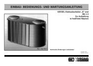
4. Installation and assembly<br />
When you are setting the telescopic attachment piece to ground<br />
level, observe the following<br />
• Installation in paved area<br />
• If the surface is to be finished with paving stones, the<br />
attachment piece must be levelled to 2 cm higher than the<br />
finished surface. When the vibratory plate compactor is<br />
used on the paving stones, the attachment piece must be<br />
included. Care must be taken that the cover plate is in place<br />
(see the illustration on the left near the section “Installation<br />
of base”).<br />
• Installation in areas that are driven over<br />
• The telescopic attachment piece must be lined using a reinforced<br />
base plate approx. 18 cm thick made of concrete,<br />
about 2.0 x 2.0 m in size (see the illustration on the right<br />
near the section “Installation of base”).<br />
The exact design of the concrete plate must be calculated<br />
according to the given local circumstances. A standard<br />
formwork plan and reinforcement drawing can be provided<br />
by <strong>KESSEL</strong>.<br />
• Other<br />
• In order to adapt installation to the existing ground level it<br />
can be necessary to saw the attachment piece to size.<br />
Make the cut as straight as possible and then deburr or<br />
chamfer it.<br />
The lift-out key provided and the operating manual must be<br />
stored on hand and dry e.g. near the electrical control unit.<br />
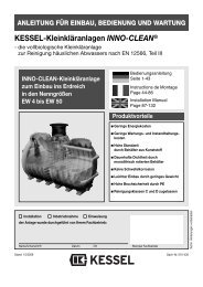
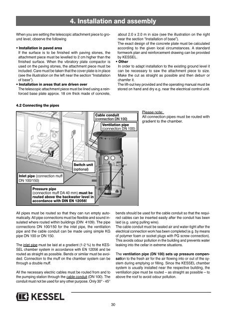
4.2 Connecting the pipes<br />
Cable conduit<br />
(connection DN 100)<br />
Ventilation pipe<br />
(connection DN 100)<br />
Please note:<br />
All connection pipes must be routed with<br />
gradient to the chamber.<br />
Inlet pipe (connection muff<br />
DN 100/150)<br />
Switch unit<br />
(optional)<br />
Pressure pipe<br />
(connection muff DA 40 mm) must be<br />
routed above the backwater level in<br />
accordance with DIN EN 12056!<br />
All pipes must be routed so that they can run empty automatically.<br />
All pipe connections must be flexible and sound insulated<br />
where routed within buildings (DIN 4109). The pipe<br />
connections DN 100/150 for the inlet pipe, the ventilation<br />
pipe and the cable conduit can be made using simple KG<br />
pipe DN 100 or DN 150.<br />
The inlet pipe must be laid at a gradient (1-2 %) to the KES-<br />
SEL chamber system in accordance with EN 12056 and be<br />
routed as straight as possible. Bends or similar must be avoided.<br />
Connection to the muff on the chamber system can be<br />
through a double muff.<br />
All the necessary electric cables must be routed from and to<br />
the pumping station through the cable conduit (DN 100). The<br />
conduit must not be used for any other purpose. Only 30° - 45°<br />
bends should be used for the cable conduit so that the required<br />
cables can be inserted easily after the conduit has been<br />
laid (e.g. using pulling wire).<br />
The cable conduit must be sealed air and water-tight after the<br />
electrical connection work has been completed (e.g. by means<br />
of polymer foam or socket plugs with PG screw connection).<br />
This avoids odour pollution in the building and prevents water<br />
leaking into the cellar in extreme situations.<br />
The ventilation pipe (DN 100) sets up pressure compensation<br />
to the fresh air for the air flowing into or out of the system<br />
during emptying or filling. Since the <strong>KESSEL</strong> chamber<br />
system is usually installed near the respective building, the<br />
ventilation pipe must be routed – as straight as possible – to<br />
above the roof to avoid odour pollution.<br />
30