KESSEL - Leichtflüssigkeitsabscheider
KESSEL - Leichtflüssigkeitsabscheider
KESSEL - Leichtflüssigkeitsabscheider

Erfolgreiche ePaper selbst erstellen
Machen Sie aus Ihren PDF Publikationen ein blätterbares Flipbook mit unserer einzigartigen Google optimierten e-Paper Software.
5. Installation and assembly<br />
When the construction pit has been filled and compacted to<br />
the lower edge of the feed and outlet connections, the feed<br />
and outlet pipes are laid frost-free and connected.<br />
Instructions for the warning system: Lay the connection<br />
cable or empty pipe during the earthworks.<br />
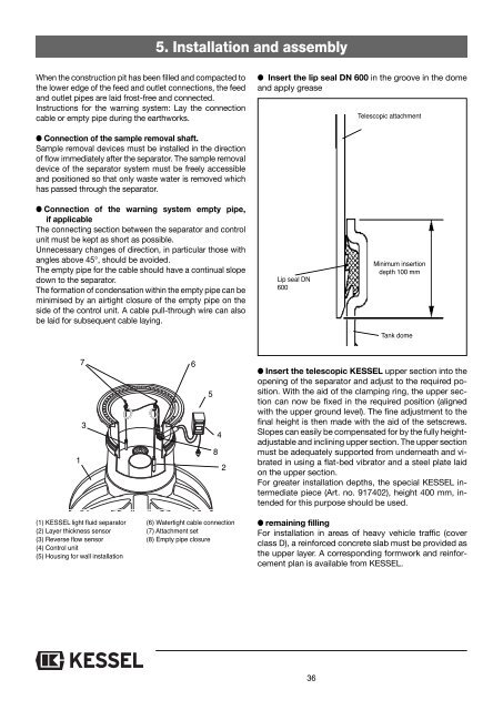
● Insert the lip seal DN 600 in the groove in the dome<br />
and apply grease<br />
Telescopic attachment<br />
● Connection of the sample removal shaft.<br />
Sample removal devices must be installed in the direction<br />
of flow immediately after the separator. The sample removal<br />
device of the separator system must be freely accessible<br />
and positioned so that only waste water is removed which<br />
has passed through the separator.<br />
● Connection of the warning system empty pipe,<br />
if applicable<br />
The connecting section between the separator and control<br />
unit must be kept as short as possible.<br />
Unnecessary changes of direction, in particular those with<br />
angles above 45°, should be avoided.<br />
The empty pipe for the cable should have a continual slope<br />
down to the separator.<br />
The formation of condensation within the empty pipe can be<br />
minimised by an airtight closure of the empty pipe on the<br />
side of the control unit. A cable pull-through wire can also<br />
be laid for subsequent cable laying.<br />
Lip seal DN<br />
600<br />
Minimum insertion<br />
depth 100 mm<br />
Tank dome<br />
1<br />
7<br />
3<br />
6<br />
5<br />
4<br />
8<br />
2<br />
● Insert the telescopic <strong>KESSEL</strong> upper section into the<br />
opening of the separator and adjust to the required position.<br />
With the aid of the clamping ring, the upper section<br />
can now be fixed in the required position (aligned<br />
with the upper ground level). The fine adjustment to the<br />
final height is then made with the aid of the setscrews.<br />
Slopes can easily be compensated for by the fully heightadjustable<br />
and inclining upper section. The upper section<br />
must be adequately supported from underneath and vibrated<br />
in using a flat-bed vibrator and a steel plate laid<br />
on the upper section.<br />
For greater installation depths, the special <strong>KESSEL</strong> intermediate<br />
piece (Art. no. 917402), height 400 mm, intended<br />
for this purpose should be used.<br />
(1) <strong>KESSEL</strong> light fluid separator<br />
(2) Layer thickness sensor<br />
(3) Reverse flow sensor<br />
(4) Control unit<br />
(5) Housing for wall installation<br />
(6) Watertight cable connection<br />
(7) Attachment set<br />
(8) Empty pipe closure<br />
● remaining filling<br />
For installation in areas of heavy vehicle traffic (cover<br />
class D), a reinforced concrete slab must be provided as<br />
the upper layer. A corresponding formwork and reinforcement<br />
plan is available from <strong>KESSEL</strong>.<br />
36