KESSEL - Leichtflüssigkeitsabscheider
KESSEL - Leichtflüssigkeitsabscheider
KESSEL - Leichtflüssigkeitsabscheider

Erfolgreiche ePaper selbst erstellen
Machen Sie aus Ihren PDF Publikationen ein blätterbares Flipbook mit unserer einzigartigen Google optimierten e-Paper Software.
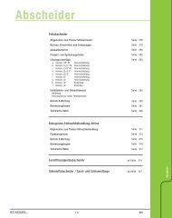
5. Installation and assembly<br />
Note: The holes for the attachment set must be drilled only<br />
at the specified positions. The holes must be made using a<br />
3.5 mm diameter drill. The original attachment screws must<br />
be used in the attachment, without plugs.<br />
The positions of the holes should be adjusted accordingly if<br />
the seal might be damaged by the drill. Under no circumstances<br />
must the cone of the rotation tank be damaged or<br />
drilled through!<br />
The extension of the cable to max. 200 m is only possible<br />
using original parts (cable and cable connectors).<br />
Information can be obtained from the <strong>KESSEL</strong> Customer<br />
Service Department under telephone no.+49 8456-27462.<br />
The use of any parts other than <strong>KESSEL</strong> original parts will<br />
invalidate the ATEX approval, the construction type approval<br />
and any guarantee claims against <strong>KESSEL</strong>.<br />
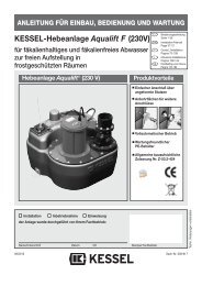
When drawing in the cable into the empty pipe to the control<br />
unit, the cable screw connections on the empty pipe closure<br />
must be tightened firmly. The union nut must then be<br />
fixed to the end of the pipe.<br />
1<br />
3<br />
4<br />
2 6 7<br />
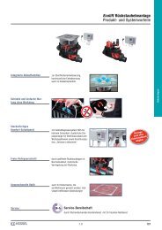
A 60 mm diameter<br />
core hole bit should<br />
be used for drilling<br />
out the conduit pipe<br />
connection hole.<br />
This is beneficial particularly for businesses with a high level of<br />
sludge. The complete separator can of course also be emptied<br />
by the sludge extraction device.<br />
If both devices are used for disposal, it must be ensured that<br />
the oil is disposed of first, followed by the sludge.<br />
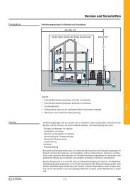
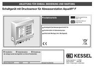
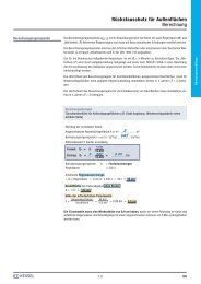
The retaining device is attached at the inlet, using the pipe<br />
clamp as shown in the drawing.<br />
Fit the oil extraction to the retaining device, set to the required<br />
height x (see Table) and fix in position.<br />
Sludge extraction<br />
Retaining device<br />
Stub connection<br />
Sludge<br />
Oil extraction<br />
5<br />
Inner side<br />
(1) Cables to the probes<br />
(2) Cable screw-fittings<br />
(3) Union nut<br />
(4) Through-seal<br />
Outer side<br />
(5) Empty pipe closure<br />
(6) Through-pipe<br />
(7) Empty pipe<br />
5.7 Oil and sludge extraction<br />
(for shaft LW 1000 on request only)<br />
For normal disposal, the hose from the suction vehicle is held<br />
in the light fluid separator and the complete contents pumped<br />
out.<br />
The volume of light fluid is however significantly less than the<br />
total volume of the separator. Assistance is provided in this case<br />
by the oil extraction device.<br />
For disposal of the light fluid, the suction hose is connected to<br />
the oil extraction device. The suction vehicle can then remove<br />
only the volume corresponding to the maximum light fluid<br />
quantity.<br />
This means a significant reduction of the disposal quantity,<br />
which together saves both time and disposal costs, and causes<br />
less wear to the separator components. In the same way<br />
as the oil extraction device, the disposal quantity can also be<br />
significantly reduced by the sludge extraction device.<br />
Fit the sludge extraction to the retaining device, feed to the bottom<br />
and then fix in position.<br />
Fit the stub connections to the attachment as shown in the drawing<br />
using the stainless steel screws provided.<br />
38