Bedienungsanleitung VIESSMANN Schaltkontakt 6840
Bedienungsanleitung VIESSMANN Schaltkontakt 6840
Bedienungsanleitung VIESSMANN Schaltkontakt 6840

Erfolgreiche ePaper selbst erstellen
Machen Sie aus Ihren PDF Publikationen ein blätterbares Flipbook mit unserer einzigartigen Google optimierten e-Paper Software.
ta 25°C<br />
IP 40<br />
Nur für trockene Räume<br />
Einleitung<br />
Introduction<br />
Der Viessmann-<strong>Schaltkontakt</strong> <strong>6840</strong> ist ein berührungsfreier Magnetschalter zum Auslösen von<br />
Schaltvorgängen durch den fahrenden Zug. Er wird direkt im Gleis montiert und ist sowohl mit<br />
Zwei- als auch mit Mittelleitergleisen verwendbar. Betätigt wird der <strong>Schaltkontakt</strong> berührungsfrei<br />
durch Fahrzeugmagnete (z.B. Viessmann 6841). Diese können an fast allen H0-Schienenfahrzeugen<br />
angebracht werden und ermöglichen, daß fahrende Züge Weichen oder Signale<br />
schalten oder Rückmeldungen beim Betrieb eines Digitalsystems auslösen.<br />
The reed contact <strong>6840</strong> from Viessmann is able to trigger switches by the running train. It is<br />
usable in combination with two- and three-rail tracks and can be mounted directly on the tracks.<br />
The contact is activated by a vehicle magnet (e.g. Viessmann 6841) without beeing touched. It<br />
can be mounted under nearly all H0 track-vehicles and makes it possible to switch turnouts and<br />
signals or to give a feedback to a digital system.<br />
Montage<br />
Mounting<br />
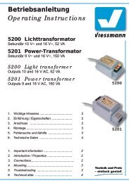
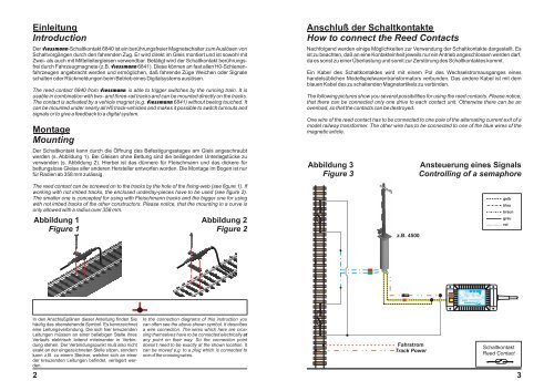
Der <strong>Schaltkontakt</strong> kann durch die Öffnung des Befestigungssteges am Gleis angeschraubt<br />
werden (s. Abbildung 1). Bei Gleisen ohne Bettung sind die beiliegenden Unterlegstücke zu<br />
verwenden (s. Abbildung 2). Hierbei ist das dünnere für Fleischmann und das dickere für<br />
bettungslose Gleise aller anderen Hersteller entworfen worden. Die Montage im Bogen ist nur<br />
für Radien ab 358 mm zulässig.<br />
Anschluß der <strong>Schaltkontakt</strong>e<br />
How to connect the Reed Contacts<br />
Nachfolgend werden einige Möglichkeiten zur Verwendung der <strong>Schaltkontakt</strong>e dargestellt. Es<br />
ist zu beachten, daß an eine Kontakteinheit jeweils nur ein Antrieb angeschlossen werden darf,<br />
da es sonst zu einer Überlastung und somit zur Zerstörung des <strong>Schaltkontakt</strong>es kommt.<br />
Ein Kabel des <strong>Schaltkontakt</strong>es wird mit einem Pol des Wechselstromausganges eines<br />
handelsüblichen Modellspielwarentransformators verbunden. Das andere Kabel ist mit dem<br />
blauen Kabel des zu schaltenden Magnetartikels zu verbinden.<br />
The following pictures show you several possibilities for using the reed contacts. Please notice,<br />
that there can be connected only one drive to each contact unit. Otherwise there can be an<br />
overload, so that the contacts can be destroyed.<br />
One wire of the reed contact has to be connected to one pole of the alternating current exit of a<br />
model railway transformer. The other wire has to be connected to one of the blue wires of the<br />
magnetic article.<br />
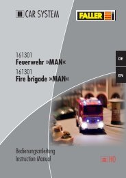
Abbildung 3<br />
Figure 3<br />
Ansteuerung eines Signals<br />
Controlling of a semaphore<br />
The reed contact can be screwed on to the tracks by the hole of the fixing-web (see figure 1). If<br />
working with not imbed tracks, the enclosed underlay-pieces have to be used (see figure 2).<br />
The smaller one is concepted for using with Fleischmann tracks and the bigger one for using<br />
with not imbed tracks of the other constructors. Please notice, that the mounting in a curve is<br />
only allowed with a radius over 358 mm.<br />
Abbildung 1<br />
Figure 1<br />
Abbildung 2<br />
Figure 2<br />
z.B. 4500<br />
gelb<br />
blau<br />
braun<br />
grau<br />
rot<br />
Lichttransformator 5200<br />
Primär<br />
230 V ~<br />
Primär 230 V 50/60 Hz<br />
Sekundär 52 VA max. 3,25 A<br />
Sekundär<br />
16 V ~<br />
Gefertigt nach<br />
VDE 0551<br />
EN 60742<br />
In den Anschlußplänen dieser Anleitung finden Sie<br />
häufig das obenstehende Symbol. Es kennzeichnet<br />
eine Leitungsverbindung. Die sich hier kreuzenden<br />
Leitungen müssen an einer beliebigen Stelle ihres<br />
Verlaufs elektrisch leitend miteinander in Verbindung<br />
stehen. Der Verbindungspunkt muß also nicht<br />
exakt an der eingezeichneten Stelle sitzen, sondern<br />
kann z.B. zu einem Stecker, welcher sich an einer<br />
der kreuzenden Leitungen befindet, verlagert werden.<br />
2<br />
In the connection diagrams of this instruction you<br />
can often see the above shown symbol. It describes<br />
a wire connection. The wires which here are crossing<br />
themselves have to be connected electrically at<br />
any point on their way. So the connection point<br />
doesn’t need to be exactly at the shown location. It<br />
can be moved e.g. to a plug which is connected to<br />
one of the crossing wires.<br />
Fahrstrom<br />
Track Power<br />
<strong>Schaltkontakt</strong><br />
Reed Contact<br />
3