Technische Hinweise - RICKMEIER Pumpentechnologie
Technische Hinweise - RICKMEIER Pumpentechnologie
Technische Hinweise - RICKMEIER Pumpentechnologie

Erfolgreiche ePaper selbst erstellen
Machen Sie aus Ihren PDF Publikationen ein blätterbares Flipbook mit unserer einzigartigen Google optimierten e-Paper Software.
Form 229607-7 (11/07)<br />
Zahnradpumpen<br />
GEAR PUMPS<br />
Allgemeine <strong>Technische</strong> Informationen<br />
Mit diesem Teil des Katalogs erhalten Sie Angaben zur Ausführung<br />
und zum Betrieb unserer Zahnradpumpen. Die mit den<br />
Pumpen ausgelieferte Betriebsanleitung enthält weitere <strong>Hinweise</strong><br />
und ist in jedem Fall zusätzlich zu beachten. Änderungen sind<br />
vorbehalten.<br />
Inhalt:<br />
1 Einsatzgebiete<br />
2 Produktbeschreibung<br />
3 Funktionsweise<br />
4 Standardausführung und Varianten<br />
5 Bezeichnungen, Typenschlüssel<br />
6 Dreh- und Durchflussrichtung<br />
7 Einsatzgrenzen<br />
8 Ausführung der Saugleitung, NPSHR-Wert<br />
9 Inbetriebnahme<br />
10 Trockenlauf<br />
11 Wartung<br />
12 Pumpenauswahl und Leistungsbedarf<br />
13 Viskositätsdiagramme<br />
1 Einsatzgebiete<br />
<strong>RICKMEIER</strong> Zahnradpumpen kommen in der Ölhydraulik, der<br />
Schmiertechnik und beim Transport unterschiedlichster Öle oder<br />
schmierfähiger Flüssigkeiten zum Einsatz.<br />
Typische Einsatzgebiete:<br />
Allgemeiner Maschinenbau, Automobilbau, Apparatebau, Baumaschinen,<br />
Bergwerkstechnik, Chemieanlagenbau, Dieselmotoren,<br />
Druckereimaschinen, Elektromotorenbau, Fahrzeugtechnik,<br />
Gasturbinen, Getriebe, Gießereitechnik, Holzbearbeitungstechnik,<br />
Industriegetriebebau, Kältetechnik, Kompressorenbau,<br />
Kraftwerkstechnik, Motorenbau, Papiermaschinen, Pumpenbau,<br />
Schiffbau, Textilmaschinen, Verdichterbau, Wasserturbinen,<br />
Walzwerkindustrie, Werkzeugmaschinen, Windenergieerzeugung,<br />
Zementanlagenbau.<br />
Typische Fördermedien:<br />
Altöl, ATF-Öl, Bohröl, Dieselkraftstoffe, Emulsionen, Getriebeöl,<br />
Heizöle, Hydrauliköl, Motorenöl, Polyglykolöl, Polyalphaolefinöl,<br />
Schneidöl, Schweröl, Wärmeträgeröl, Ziehöl.<br />
Andere Fördermedien auf Anfrage.<br />
P U M P E N T E C H N O L O G I E<br />
Zahnradpumpen Ventile Sonderprodukte Systeme<br />
@ www.rickmeier.de<br />
Seite:<br />
1<br />
2<br />
3<br />
4<br />
4<br />
5<br />
6<br />
8<br />
9<br />
9<br />
9<br />
10<br />
12<br />
General Technical Information<br />
This section of the catalog contains general information and<br />
instructions for the operation of our gear pumps. Our pumps are<br />
delivered with operating instructions that include important notes,<br />
which must also be respected in every case. We reserve all rights<br />
to technical changes.<br />
Contents:<br />
1 Applications<br />
2 Product description<br />
3 Function mode<br />
4 Standard version and variations<br />
5 Identifiers, type code<br />
6 Sense of rotation, direction of flow<br />
7 Operation limits<br />
8 Suction pipe design, NPSHR-value<br />
9 Commissioning<br />
10 Dry-running<br />
11 Maintenance<br />
12 Choice of pumps and power input<br />
13 Viscosity diagrams<br />
Page:<br />
1<br />
2<br />
3<br />
4<br />
4<br />
5<br />
6<br />
8<br />
9<br />
9<br />
9<br />
10<br />
12<br />
1 Applications<br />
<strong>RICKMEIER</strong> gear pumps are used in the field of oil hydraulics,<br />
lubrication technology and for the transport of the most different<br />
oils or lubricating liquids.<br />
Typical fields of applications:<br />
General machine building, apparatus engineering, construction<br />
machines, mining industry, chemical industry, diesel engines,<br />
printing machines, electric motor construction, automotive engineering,<br />
gas turbines, gears, foundry technology, wood machining,<br />
industrial gear transmissions, refrigeration technology, compressor<br />
manufacturing, power generation, motor construction,<br />
paper machines, pump industry, shipbuilding, textile machines,<br />
compressor manufacturing, water turbines, rolling mills, tooling<br />
machines, wind energy generation, and cement plant building.<br />
Typical flow media:<br />
Used oil, ATF-oil, emulsions, diesel fuels, gear lubricant oil,<br />
heating fuel oil, hydraulic fluid, crankcase oil, polyglycol oil,<br />
polyalphaolefin oil, cutting oil, heavy oil, thermal oil, drawing<br />
compound. Other fluids on request.<br />
1
2<br />
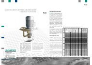
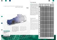
2 Produktbeschreibung<br />
<strong>RICKMEIER</strong> Zahnradpumpen zeichnen sich durch einen<br />
einfachen und robusten Aufbau aus, der in Abb. 1 dargestellt ist.<br />
Eine Pumpe in Standardausführung besteht aus Rädergehäuse<br />
(1), Antriebsdeckel (2) und Schlussdeckel (3), der optional auch<br />
mit einem Druckbegrenzungsventil (7) ausgeführt werden kann<br />
sowie den gehärteten Radwellen (4).<br />
Großzügig dimensionierte, sonderbeschichtete Mehrstoff-<br />
Gleitlager (5) besitzen eine hohe Lebensdauer und haben sehr<br />
gute Trockenlaufeigenschaften. Die Wellenabdichtung wird<br />
standardmäßig mit einem Radialwellendichtring (6) oder, wo<br />
erforderlich, mit einer Gleitringdichtung ausgeführt. Eine kurze,<br />
geradlinige Führung der Strömungskanäle bewirkt ein gutes<br />
Ansaugverhalten und leisen Lauf. Gemeinsam mit einer<br />
speziellen Ausführung der Verzahnung und des Rädergehäuses<br />
wird ein extrem niedriges Geräuschniveau während des Betriebs<br />
sichergestellt.<br />
Rädergehäuse<br />
Antriebsdeckel<br />
Schlussdeckel<br />
Radwellen<br />
Dichtungen<br />
Gleitlager<br />
Standard<br />
EN-GJL-250<br />
(GG-25)*<br />
Einsatzstahl<br />
NBR<br />
Verbundlager<br />
alternativ<br />
EN-GJS-400-18-LT<br />
(GGG-40.3)*<br />
auf Anfrage<br />
FPM, u.a.<br />
auf Anfrage<br />
2 Product description<br />
P U M P E N T E C H N O L O G I E<br />
Zahnradpumpen Ventile Sonderprodukte Systeme<br />
<strong>RICKMEIER</strong> gear pumps excel in a very simple and robust<br />
construction that has been represented in Fig. 1. A pump in the<br />
standard version consists of the gear casing (1), driving cover (2)<br />
and end cover (3), with an option for a pressure relief valve (7) plus<br />
the hardened gear wheels (4).<br />
Compound journal bearings (5) with special coating and in ample<br />
dimension demonstrate a long life having very good dry-running<br />
capability. The shaft sealing, as a standard, is equipped with a<br />
radial shaft seal (6) or, where required, with a mechanical seal. A<br />
short and straight-line alignment of the flow channels provides for<br />
a good suction capability and quiet running.The combination with<br />
a special version of gearing and gear casing assures extremely<br />
low levels of noise during operation.<br />
6 2 5 4 5 1 3 7 8<br />
Abb. 1: Zahnradpumpe - Standardausführung Fig. 1: Gear pump - standard version<br />
Werkstoffe Materials<br />
gear casing<br />
driving cover<br />
end cover<br />
gear wheels<br />
seals<br />
journal bearings<br />
* früher gebräuchliche Bezeichnungen * previously used descriptions<br />
standard<br />
EN-GJL-250<br />
(GG-25)*<br />
alternative<br />
EN-GJS-400-18-LT<br />
(GGG-40.3)*<br />
hardened steel on request<br />
NBR<br />
FPM, a.o.<br />
compound bearings on request
Form 229607-7 (11/07)<br />
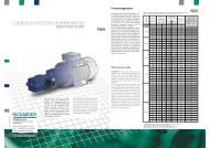
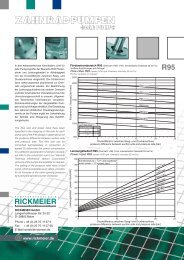
3 Funktionsweise<br />
Zahnradpumpen sind rotierende Verdrängerpumpen. Bei<br />
Drehung der Radwellen wird das in den Zahnzwischenräumen<br />
eingeschlossene Medium von der Saug- zur Druckseite transportiert<br />
und dort durch die ineinander greifenden Zähne zur<br />
Druckseite hin verdrängt (siehe Abb. 2). Durch den Transport des<br />
Fördermediums entsteht auf der Saugseite der Pumpe eine<br />
Druckabsenkung, die das Fördermedium durch Nachströmen<br />
ausgleicht, wodurch der Förderprozess aufrecht erhalten wird.<br />
Da dieser Vorgang bei gasförmigen wie flüssigen Medien in<br />
gleicher Weise erfolgt, ist die Pumpe in der Lage, die Saugleitung<br />
selbst zu entlüften, bis sie vollständig mit flüssigem Fördermedium<br />
gefüllt ist.<br />
Hinweis: die Entlüftung der Saugleitung ist nur dann nicht möglich,<br />
wenn diese entweder nicht vollständig dicht ist, so dass sich kein<br />
Unterdruck aufbauen kann oder wenn der Druck im saugseitigen<br />
Rohrleitungssystem/Behälter zu gering ist (Vakuum oder zu weit<br />
unterhalb der Pumpe befindlicher Flüssigkeits-spiegel), um ein<br />
Nachströmen des Fördermediums zuzulassen.<br />
Ein Rückschlagventil auf der Druckseite der Pumpe kann ebenfalls<br />
diese Entlüftung verhindern (siehe auch “9 Inbetriebnahme”).<br />
Bei geschlossener Druckleitung ist keine Entlüftung der<br />
Saugleitung möglich (Entlüftungsventil vorsehen).<br />
Druckbegrenzungsventil:<br />
Das optional im Schlussdeckel der Pumpe integrierte Druckbegrenzungsventil<br />
ist als federbelastetes Ventil ausgeführt. Es darf<br />
nur als gelegentlich ansprechendes Ventil zur Druckbegrenzung<br />
eingesetzt werden. Muss eine größere Teilmenge des Förderstroms<br />
über längere Zeiträume abgeführt werden, ist ein separates<br />
Ventil mit Rückführleitung zum Saugbehälter in der Rohrleitung<br />
vorzusehen (z.B. unsere VentileTyp RSn, DBV40, Db9).<br />
3 Function mode<br />
Gear pumps are rotating positive displacement pumps. The<br />
rotation of the gear wheels causes the medium enclosed between<br />
the tooth space to be transported from the suction side to the<br />
pressure side.There it will be displaced towards the pressure side<br />
by the teeth that catch in (p.r.t. Fig. 2). A pressure decreasement<br />
on the pump's suction side results from the transport of the flow<br />
medium, which is compensated for by the flow medium that<br />
continues flowing in thereby maintaining the delivery process.<br />
Ansaugen / suck Transport / transport Verdrängen / displace<br />
Abb. 2: Förderprinzip Zahnradpumpe Fig. 2: Gear pump delivery principle<br />
P U M P E N T E C H N O L O G I E<br />
Zahnradpumpen Ventile Sonderprodukte Systeme<br />
As this process is the same for gaseous and liquid media, the<br />
pump itself is capable of draining the suction pipe, until the same<br />
has been completely filled with the liquid flow medium.<br />
Note: no draining of the suction pipe is possible, when the same<br />
either is not fully leakproof, with the result that no negative<br />
pressure can build up, or, when the pressure in the pipe<br />
system/tank is too low on the suction side (vacuum or too low<br />
suction level below the pump) to allow the flow medium to continue<br />
flowing in. A nonreturn valve on the pump's pressure side may also<br />
prevent this draining (please refer also to section “9<br />
Commissioning”). A fully closed pressure pipe allows no draining<br />
of the suction pipe (install a vent valve).<br />
Pressure relief valve:<br />
The pressure relief valve that has been integrated as an option into<br />
the pump's end cover has been executed as a spring-loaded valve.<br />
It may be used as a valve reacting occasionally to relief the<br />
pressure. Any demand to deviate a larger volume of the flow for<br />
extended periods of time requires a separate valve (with return to<br />
the suction tank) to be installed in the piping (e.g. our RSn, DBV40,<br />
DB9 type valves).<br />
3
4<br />
4 Standardausführung und Varianten<br />
Standard<br />
Varianten auf Anfrage<br />
Befestigungs- quadratisch<br />
mit angeschraubtem Fuß<br />
flansch<br />
rund, oval<br />
Anschlüsse R25 mit Einschraubloch metrisches SAE-Bild<br />
R35, R45 u. R65<br />
metrisches SAE-Bild<br />
R95 Flanschbild nach<br />
Rickmeier Norm<br />
DIN-Bild<br />
Wellenende zylindrisch mit zylindrisch ohne Passfeder,<br />
Passfeder<br />
Konus, Mitnehmer, Verzahnung<br />
Wellenabdich- Radialwellendichtring ohne Dichtung, Gleitringdichtung,<br />
tung<br />
Mehrfachdichtung zur Medientrennung<br />
Druckventil mit oder ohne Druck- Druckregelventil mit externer<br />
begrenzungsventil Ansteuerung<br />
Umsteuerventil ohne<br />
Umsteuerventil für R35, R45 und<br />
R65<br />
Vorsatzlager ohne<br />
zusätzliche Lagerung im Antriebsdeckel,<br />
separate Vorsatzlagereinheit<br />
Anzahl<br />
Einfachpumpe Zweifachpumpe, ohne oder mit<br />
Förderströme<br />
Abdichtung zwischen den Fächern<br />
Korrosionsschutz Einfachlackierung mit<br />
1-Komponenten-<br />
Alkydharzlack<br />
RAL 60M, ca. 30μm<br />
nach Kundenvorschrift<br />
5 Bezeichnungen, Typenschlüssel<br />
Die Bezeichnung der <strong>RICKMEIER</strong> Zahnradpumpen erfolgt nach<br />
folgendem Schlüssel:<br />
R xxx/xxxx FL<br />
FU<br />
Typ type<br />
3<br />
Geometrisches Verdrängungsvolumen [cm ]<br />
3<br />
geometrical displacement volume [cm ]<br />
Bauform design<br />
Wellenende shaft end<br />
Ventil/max. Öffnungsdruck [bar] valve/max.set pressure [bar]<br />
Wellendichtung shaft seal<br />
Anschlussgröße connecting dimension<br />
Drehrichtung sense of rotation<br />
Sonderausführung customized version<br />
- Z<br />
K<br />
M<br />
V<br />
4 Standard version and variations<br />
fix flange<br />
connection<br />
shaft end<br />
shaft seal<br />
pressure valve<br />
flow reversal<br />
valve<br />
additional front<br />
bearing<br />
no. Of<br />
flow rates<br />
corrosion<br />
protection<br />
standard<br />
rectangular<br />
R25: with thread<br />
R35, R45, R65:<br />
metric SAE flange<br />
R95: Rickmeier<br />
standard<br />
cylindrical with<br />
feather key<br />
radial shaft seal<br />
with or without<br />
relief valve<br />
none<br />
none<br />
single<br />
1-component alkyd<br />
resin RAL 6011,<br />
approx. 30μm<br />
5 Identifiers, type code<br />
P U M P E N T E C H N O L O G I E<br />
Zahnradpumpen Ventile Sonderprodukte Systeme<br />
variations on request<br />
with foot<br />
circular, oval<br />
metric SAE flange<br />
DIN flange dimension<br />
cylindrical without feather key<br />
conical, driver, thread<br />
without seal, mechanical seal,<br />
double seal for media separation<br />
pressure control valve with<br />
external initiation<br />
available for R35, R45, R65<br />
integrated in driving cover<br />
or<br />
separate bearing unit<br />
double, with or without separation<br />
on customer’s demand<br />
<strong>RICKMEIER</strong> gear pumps are identified by the following code:<br />
- DBxxx - W<br />
GLRD<br />
-<br />
Gxxx<br />
SAExxx<br />
DNxxx<br />
- R<br />
L<br />
C<br />
UNI<br />
Erläuterung<br />
Explanation<br />
FL Flanschpumpe<br />
FL flange pump<br />
FU Fußpumpe<br />
FU foot pump<br />
Z Wellenende zylindrisch<br />
Z cylindrical shaft end<br />
K Wellenende konisch<br />
K conical shaft end<br />
M Wellenende mit Mitnehmer<br />
M shaft end with driver<br />
V Wellenende mit Verzahnung<br />
V shaft end with spline<br />
DB mit Druckbegrenzungsventil<br />
DB with pressure relief valve<br />
W Radialwellendichtung<br />
W radial shaft seal<br />
GLRD Gleitringdichtung<br />
GLRD mechanical seal<br />
G Einschraubgewinde<br />
G thread<br />
SAE Anschlussbild<br />
SAE connecting dimensions<br />
DN Flanschbild R95 DN nominal flange dimension<br />
R rechtsdrehend<br />
R rotating clockwise<br />
L linksdrehend<br />
L rotating counter-clockwise<br />
C rechts- und linksdrehend<br />
C rotating clockwise and counter-clockwise<br />
(wechselnde Förderrichtung)<br />
(changing direction of flow)<br />
UNI Förderrichtung unabhängig von Drehrichtung<br />
UNI direction of flow independ. of sense of rot.<br />
SO Sonderausführung<br />
SO customized version<br />
- SO
Form 229607-7 (11/07)<br />
6 Dreh- und Durchflussrichtung<br />
Wenn nicht anders lautend bestellt, ist der Drehsinn<br />
„rechtsdrehend“ (s. Abb. 3).<br />
R<br />
L<br />
R<br />
rechtsdrehend<br />
clockwise<br />
Zuordnungspfeil für Drehrichtungskennzeichnung<br />
L,R Drehrichtung, bei Blick auf Antriebswelle<br />
R - Rechts<br />
L - Links<br />
Durchflussrichtung<br />
Abb. 3: Dreh- und Förderrichtung<br />
Feststellen der Drehrichtung:<br />
Der auf dem Rädergehäuse befindliche Pfeil zeigt zum<br />
Schlussdeckel, dort auf den Buchstaben „R“ für rechtsdrehend<br />
bzw. „L“ für linksdrehend (vergl. Abb. 3).<br />
Umkehr der Drehrichtung:<br />
Die Pumpen der Baugrößen R25 bis R65 sind so konzipiert, dass<br />
der Drehsinn nachträglich geändert werden kann. Es ändert sich<br />
dann natürlich auch die Durchflussrichtung.<br />
Vor dem Umbau auf eine andere Drehrichtung und damit der<br />
Umkehr der Förderrichtung sollte Rücksprache mit unseren<br />
Mitarbeitern gehalten werden.<br />
R<br />
L<br />
R<br />
6 Sense of rotation, direction of flow<br />
Unless the order specifies to the contrary, the sense of rotation is<br />
“clockwise" (p.r.t. Fig. 3).<br />
L<br />
linksdrehend<br />
counter-clockwise<br />
sense of rotation, identification arrow<br />
L,R sense of rotation, view on shaft end<br />
R - clockwise<br />
L - counter-clockwise<br />
direction of delivery<br />
Fig. 3: Sense of rotation and direction of flow<br />
P U M P E N T E C H N O L O G I E<br />
Zahnradpumpen Ventile Sonderprodukte Systeme<br />
Determining the direction:<br />
The arrow on the gear casing points towards the end cover. The<br />
letter "R" stands for clockwise respectively "L" for counterclockwise<br />
(compare to Fig. 3).<br />
Reversing the direction:<br />
The pumps of the sizes R25 to R65 have been designed in a way<br />
that the sense of rotation can be changed later. Naturally, the<br />
direction of flow will change as well.<br />
Before changing of the sense of rotation we recommend<br />
assistance by our engineers.<br />
L<br />
5
6<br />
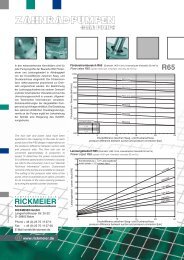
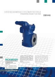
7 Einsatzgrenzen<br />
Die dargestellten Einsatzgrenzen gelten für Pumpen in der<br />
Standardausführung. Sind Überschreitungen der angegebenen<br />
Grenzen erforderlich, sprechen Sie bitte mit unseren Mitarbeitern.<br />
Fördermedium:<br />
Als Voraussetzung für lange Lebensdauer und höchste Betriebssicherheit<br />
soll das Fördermedium schmierfähig und nach<br />
Möglichkeit sauber und nicht korrosiv sein, in jedem Fall aber frei<br />
von harten Beimengungen. Zusätzlich gelten folgende Bereiche:<br />
Eigenschaft<br />
kinematische Viskosität<br />
Verschmutzungsgrad<br />
Gasgehalt (ungelöst)<br />
Temperatur (NBR Dichtungen)<br />
Temperatur (FPM Dichtungen)<br />
Pumpenaggregat<br />
Flanschpumpe<br />
1) ungelöstes Gas im Fördermedium kann zu erhöhter Schallemission<br />
führen<br />
2) Bei Einsatz über 80°C sind unter Umständen besondere Maßnahmen<br />
(z.B. warmfeste Kupplung, Druckbegrenzungsventil mit warmfester Feder,<br />
etc.) erforderlich. Bitte sprechen Sie mit unseren Mitarbeitern.<br />
Eintrittsdruck:<br />
Dauerdruck nach DIN 24312, Erweiterung der angegebenen<br />
Bereiche auf Anfrage.<br />
Wellendichtung<br />
Radialwellendichtring, Stillstand<br />
Radialwellendichtring bei Betrieb<br />
Gleitringdichtung, Stillstand<br />
Gleitringdichtung bei Betrieb<br />
3) manometrisch<br />
max. Druckdifferenz<br />
max. pressure difference [bar]<br />
25<br />
20<br />
15<br />
10<br />
5<br />
characteristics<br />
kinematic viscosity<br />
degree of contamination<br />
gas content (undissolved)<br />
temperature (NBR seals)<br />
temperature (FPM seals)<br />
gear pump unit<br />
flange pump<br />
shaft seal<br />
radial shaft seal, standstill<br />
2<br />
Abb. 4: Zulässige Druckdifferenz (Viskosität 33 mm /s)<br />
radial shaft seal in opperation<br />
mechanical seal, standstill<br />
mechanical seal in opperation<br />
P U M P E N T E C H N O L O G I E<br />
Zahnradpumpen Ventile Sonderprodukte Systeme<br />
7 Operation limits<br />
The limitations presented herein apply for pumps in the standard<br />
version. Please contact us, whenever the specified limits need to<br />
be exceeded.<br />
Flow medium:<br />
The flow medium used should demonstrate good lubricity as a<br />
condition for long lifetime and top operational safety. If possible,<br />
the medium should be clean and non-corrosive, but in all cases<br />
free from undesirable hard constituents. Consideration must be<br />
given also to the following:<br />
Einheit unit<br />
2<br />
mm /s<br />
ISO 4406<br />
Vol.-%<br />
°C<br />
°C<br />
°C<br />
1) undissolved gas in the medium may cause higher noise emissions<br />
2) the use above 80°C may require particular measures (e.g. high<br />
temperature couplings or springs etc.). Please contact us.<br />
Inlet pressure:<br />
Continuous pressure under DIN 24312. Expansion of the<br />
specified ranges on request.<br />
Einheit unit<br />
3)<br />
bar bar<br />
3)<br />
bar bar 3)<br />
bar bar<br />
3)<br />
bar bar<br />
3) manometric<br />
min. min.<br />
7<br />
-<br />
-<br />
-25<br />
max. max.<br />
15000<br />
21/19/17<br />
1)<br />
10<br />
80<br />
2)<br />
130<br />
Drehzahl speed [1/min]<br />
2<br />
Fig. 4: Permissible pressure difference (viscosity 33 mm /s)<br />
-25<br />
-25<br />
min. min.<br />
-0,4<br />
-0,4<br />
-0,4<br />
-0,4<br />
R95 R65<br />
R45 R35<br />
R25<br />
0<br />
0 400 800 1200 1600 2000 2400 2800 3200 3600<br />
2)<br />
160<br />
max. max.<br />
5<br />
0,5<br />
10<br />
10
Form 229607-7 (11/07)<br />
Drehzahlbereiche:<br />
Die allgemeinen Drehzahlgrenzen sind in Abb. 4 angegeben. Bei<br />
hoher Viskosität wird der nutzbare Bereich nach oben begrenzt,<br />
siehe Abb. 5.<br />
max. zul. Drehzahl n max = f(n)<br />
max. permiss. speed n max = f(n)<br />
-1<br />
Drehzahl nmax speed n max [min ]<br />
3600<br />
3000<br />
2000<br />
1000<br />
0<br />
Abb. 5: Zulässige Drehzahlbereiche<br />
Zulässige Axialkräfte auf das Wellenende:<br />
2<br />
(Viskosität 33 mm /s, Drehzahl 1450 1/min, bei Drehrichtung<br />
“rechts” in Richtung Antrieb, bei Drehrichtung “links” in Richtung<br />
Pumpe, Antriebsritzel rechtssteigend):<br />
R25: 90 N R65: 800 N<br />
R35: 200 N<br />
R95: 1500 N<br />
R45: 300 N<br />
10 50<br />
Zulässige Radialkräfte auf das Wellenende (s. Abb. 6):<br />
2<br />
(Mitte Wellenzapfen,Viskosität 33 mm /s)<br />
max. Radialkraft max. radial force [N]<br />
15000<br />
10000<br />
2000<br />
1000<br />
200<br />
100<br />
20<br />
2<br />
10<br />
2<br />
Abb. 6: Zulässige Radialkräfte (Viskosität 33 mm /s)<br />
2<br />
5·10<br />
3<br />
10<br />
2<br />
Viskosität viscosity n [mm /s]<br />
3<br />
Verdrängungsvolumen displacement volume [cm ]<br />
Speed ranges:<br />
The general speed limits have been specified in Fig.4. Higher<br />
viscosity will limit the permissible range towards the top, p.r.t. Fig. 5.<br />
3<br />
5·10<br />
4<br />
10<br />
Fig. 5: Permissible speed ranges<br />
Permissible axial forces on the shaft end:<br />
2<br />
(viscosity 33 mm /s, speed 1450 rpm, for "clockwise" rotation in<br />
the direction of the drive, for "counter-clockwise" rotation in the<br />
direction of the pump driving pinion with right-hand teeth):<br />
R25: 90 N R65: 800 N<br />
R35: 200 N R95: 1500 N<br />
R45: 300 N<br />
Permissible radial forces on the shaft end:<br />
2<br />
(center shaft journal, viscosity 33 mm /s)<br />
1 2 5 10 20 50 100 200 500 1000 1500<br />
P U M P E N T E C H N O L O G I E<br />
Zahnradpumpen Ventile Sonderprodukte Systeme<br />
4<br />
5·10<br />
-1<br />
n = 1450 min<br />
-1<br />
n = 500 min<br />
2<br />
Fig. 6: Permissible radial forces (viscosity 33 mm /s)<br />
7
8<br />
8 Ausführung der Saugleitung, NPSHR-Wert<br />
Die Anschlussnennweiten der Pumpen sind so gewählt, dass<br />
diese in den meisten Anwendungsfällen einen technisch und wirtschaftlich<br />
optimalen Richtwert für die Dimensionierung der Saugleitung<br />
darstellen. Für einen einwandfreien Betrieb ist allerdings<br />
letztlich erforderlich, dass der statische Druck unmittelbar am<br />
Eintritt in die Pumpe unter keinen Betriebsbedingungen weniger<br />
als -0,4 bar (entsprechend 0,6 bar absolut) beträgt.<br />
Es empfiehlt sich daher immer, den niedrigsten während des Betriebs<br />
am Pumpeneintritt möglichen statischen Druck unter Berücksichtigung<br />
aller Rohrleitungs- und ggfs. Armaturenwiderstände<br />
genau zu berechnen, bevor die Ausführung der Saugleitung<br />
endgültig festgelegt wird.<br />
Dies insbesondere dann, wenn von den Nennbetriebsbedingungen<br />
für Viskosität, Temperatur und Drehzahl abgewichen<br />
oder in der Saugleitung ein Filter vorgesehen wird, der sich im<br />
Laufe der Zeit zusetzen kann. In diesem Fall ist es ratsam, den<br />
Pumpeneintrittsdruck durch ein Druckmessgerät möglichst nah<br />
vor der Pumpe zu überwachen.<br />
Falls kein Messanschluss in der Saugleitung zur Verfügung steht,<br />
kann hierzu bei Pumpen mit Druckbegrenzungsventil auch der<br />
der Saugseite zugewandte Manometeranschluss (siehe Abb. 1<br />
Pos. 8) verwendet werden. Im übrigen muss die Saugleitung<br />
absolut dicht sein, damit keine Luft angesaugt wird. Starke<br />
Geräuschentwicklung weist auf das Ansaugen von Luft oder das<br />
Vorhandensein von Kavitation infolge zu niedrigen Pumpeneintrittsdrucks<br />
hin.<br />
Der häufig zum Vergleich mit dem NPSHA-Wert einer Anlage<br />
benötigte NPSHR-Wert der Pumpen kann Abb. 7 entnommen<br />
werden.<br />
NPSHR [m]<br />
11<br />
10<br />
9<br />
8<br />
7<br />
6<br />
Abb. 7: NPSHR Fig. 7: NPSHR<br />
8 Suction pipe design, NPSHR-value<br />
P U M P E N T E C H N O L O G I E<br />
Zahnradpumpen Ventile Sonderprodukte Systeme<br />
The connecting dimensions of the pumps have been selected in a<br />
way that they will represent a guideline for the dimensioning of the<br />
suction pipe, which has been optimized technically and<br />
economically. For a perfect operation, however, it is necessary that<br />
the static pressure direct at the entry of the pump, on no operating<br />
condition, falls below -0,4 bar (0,6 bar absolute).<br />
Thus it is always recommendable to calculate the lowest static<br />
pressure that may occur at the pump’s entry side during the<br />
operation considering all piping and, if needed, all fitting<br />
resistances prior to finalizing the execution of the suction pipe.<br />
This applies in particular, when the nominal operating conditions<br />
for viscosity, temperature and speed are deviated from, or, when a<br />
filter in the suction pipe has been planned that may clog in the<br />
course of time. In such a case it would be advisable to monitor the<br />
pump entry pressure as close as possible in front of the pump.<br />
If no connection for measuring devices has been provided in the<br />
suction pipe for pumps with a pressure relief valve, then the<br />
pressure gauge connection that is facing the suction side may also<br />
be used (p.r.t. Fig. 1, pos. 8). Furthermore the suction pipe must be<br />
absolutely leakproof to avoid any sucking in of air. A strong<br />
formation of noise is an indication that air is sucked in or for the<br />
presence of cavitation resulting from an insufficient pump entry<br />
pressure.<br />
The NPSHR-value of the pumps that is frequently required to<br />
compare it with the NPSHA-value of a system may be obtained<br />
from Fig. 7.<br />
5<br />
600 700 800 900 1000 1100<br />
3<br />
Dichte des Fördermediums density of fluid [kg/m ]
Form 229607-7 (11/07)<br />
9 Inbetriebnahme<br />
Vor Inbetriebnahme der Pumpe ist auf Übereinstimmung<br />
zwischen Antriebsdrehsinn und Pumpendrehsinn zu achten. Bei<br />
der Überprüfung des Antriebsdrehsinns wird zweckmäßigerweise<br />
die Kupplung gelöst, damit die Pumpe nicht angetrieben wird. Ist<br />
dies nicht möglich, so sind zumindest die Rohranschlüsse zu<br />
entfernen, damit nicht bei falschem Drehsinn die Pumpe zerstört<br />
wird. Dies ist z.B. leicht möglich, wenn in der Saugleitung ein<br />
Rückschlagventil eingebaut ist. Trockenlauf ist zu vermeiden<br />
(siehe auch „10 Trockenlauf“). Wenn die Pumpe längere Zeit<br />
gelagert wurde, ist sie vor Inbetriebnahme mit dem<br />
Fördermedium aufzufüllen.<br />
Wird die Pumpe so eingebaut, dass die Radwellen übereinander<br />
liegen, verbleibt in der Pumpe auch bei Stillstand ein kleiner Rest<br />
Fördermedium. Damit ist für die Wiederinbetriebnahme auch<br />
nach längeren Stillstandszeiten maximale Ansaugfähigkeit<br />
gegeben.<br />
Bei Betrieb zweier parallel arbeitender Pumpen, die durch<br />
Rückschlagventile gegeneinander abgesichert sind, sollten beide<br />
Pumpen auf der Druckseite entlüftet werden. Dasselbe gilt für eine<br />
gegen ein geschlossenes System arbeitende Pumpe (belastetes<br />
Rückschlagventil o.ä.).<br />
10 Trockenlauf<br />
Trockenlauf tritt häufig bei der Inbetriebnahme (Füllen der<br />
Saugleitung) oder während des Betriebs auf, wenn die<br />
Nachversorgung mit Fördermedium unterbrochen wurde.<br />
Pumpen, die zuvor im Inneren mit Fördermedium benetzt waren,<br />
können in diesem Zustand bis zu 20 Minuten (unbenetzt: 2<br />
Minuten) betrieben werden, wenn folgende Voraussetzungen<br />
erfüllt sind:<br />
- Antrieb der Pumpe über Kupplung, d.h. radialkraftfrei<br />
- Druck an Ein- und Austritt der Pumpe näherungsweise gleich<br />
Bei Pumpen, die über Ritzel, Kette oder Riemen angetrieben<br />
werden, ist Trockenlauf nicht zulässig und muss vom Betreiber<br />
vermieden werden (Pumpe vor Inbetriebnahme mit Fördermedium<br />
füllen).<br />
11 Wartung<br />
<strong>RICKMEIER</strong> Zahnradpumpen sind in der Regel wartungsarm,<br />
wenn sie innerhalb der zulässigen Einsatzgrenzen betrieben<br />
werden (siehe „7 Einsatzgrenzen”).<br />
Wird eine Zahnradpumpe infolge von Verschleiß unbrauchbar, so<br />
muss sie ersetzt werden. Der Einbau von Ersatzteilen führt nicht<br />
wieder zur ursprünglichen Leistung.<br />
9 Commissioning<br />
P U M P E N T E C H N O L O G I E<br />
Zahnradpumpen Ventile Sonderprodukte Systeme<br />
Prior to the initial operation of the pump check that the driver's and<br />
the pump's sense of rotation have been coordinated. During the<br />
check of the drive's sense of rotation it is recommended to release<br />
the coupling to prevent the pump from being driven. Should this be<br />
impossible, then the pipe connections must be removed at least to<br />
avoid any destruction of the pump in case of a wrong sense of<br />
rotation. This is always easy to achieve, when a nonreturn valve<br />
has been installed in the suction pipe. To avoid dry-running (p.r.t.<br />
"10 dry-running" as well) make sure to refill the flow medium<br />
before the pump is operated again after any prolonged storage<br />
period.<br />
A small rest of the flow medium will always remain in the pump<br />
during shutdown even, when the pump has been installed in a<br />
way that the gear shafts lie above each other. This ensures a<br />
maximum suction capability for the reoperation even after<br />
prolonged shutdown periods.<br />
For operation of two pumps working in parallel, which have been<br />
secured against each other by nonreturnvalves, it is<br />
recommended to prime both pumps on the pressure side. The<br />
same applies for a pump operating against a closed system<br />
(loaded nonreturnvalve or the like).<br />
10 Dry-running<br />
Dry-running occurs frequently during the initial operation (priming<br />
of the suction line) or during the operation, when the continuous<br />
flow of the flow medium has been interrupted.<br />
Pumps, which previously have been wetted with flow medium<br />
inside, may be operated in this condition for 20 minutes (not<br />
wetted: 2 minutes), provided the following conditions are met:<br />
- the pump is driven by a clutch, i.e. is free of radial forces<br />
- the pressure on the pump's input and output side is nearly the<br />
same<br />
No dry-running has been allowed for pumps, which are driven by a<br />
pinion, chain or belt, and this must definitely be avoided by the<br />
operator (fill the pump with flow medium before operation).<br />
11 Maintenance<br />
<strong>RICKMEIER</strong> gear pumps, as a rule, are low-maintenance, always<br />
provided they are operated within the permissible limitations (p.r.t.<br />
"7 Operation limits"). Any gear pump that becomes unserviceable<br />
due to wear must be replaced. The installation of spare parts is<br />
insufficient to guarantee the original performance.<br />
9
10<br />
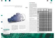
12 Pumpenauswahl und Leistungsbedarf<br />
a) Erforderliches Verdrängungsvolumen Vg bestimmen:<br />
Vg theo<br />
Q :<br />
erf<br />
n<br />
Beispiel:<br />
Q erf<br />
n<br />
ergibt: Vg theo<br />
gewählt:<br />
b) Förderstrom Q bestimmen:<br />
Q » Q Diagramm + Vg • ( n [1/min] - 1450 1/min )<br />
QDiagramm = Förderstrom aus Kennfeld<br />
n = Drehzahl<br />
Vg = Verdrängungsvolumen der Pumpe<br />
Beispiel:<br />
Vg (R95/1120) =<br />
3<br />
1120 cm = 1,120 L<br />
Druckdifferenz Dp = 6 bar<br />
Q Diagramm (R95/1120) = 1576 dm³/min<br />
2<br />
bei n = 1450 1/min und n = 33 mm /s<br />
Drehzahl n = 970 1/min<br />
ergibt: Q » 1038 dm³/min<br />
=<br />
=<br />
=<br />
=<br />
Q / n<br />
erf<br />
= geforderter Volumenstrom<br />
=<br />
Drehzahl<br />
3<br />
60 m /h = 1000 dm³/min<br />
970 1/min (gewählt)<br />
3<br />
1,031 L = 1031 cm<br />
3<br />
R95/1120 mit Vg = 1120 cm<br />
Weicht die kinematische Viskosität des Fördermediums von dem<br />
2<br />
Wert 33 mm /s ab (für den die Kennfelder gelten), so kann der<br />
Förderstrom ebenfalls geringfügig von den ermittelten Werten<br />
abweichen. Dabei gilt, dass geringere Viskosität zu einer<br />
Abnahme, höhere Viskosität zu einer Zunahme gegenüber den<br />
Kennfeldwerten führen kann.<br />
Wegen weiterer Abhängigkeiten des Förderstroms von der<br />
Druckdifferenz und der Drehzahl wird hier auf eine detaillierte<br />
Darstellung verzichtet. Besonders bei den kleineren Baugrößen<br />
und sehr geringer Viskosität raten wir zu einer genauen<br />
Überprüfung der Förderdaten durch unsere Mitarbeiter.<br />
12 Choice of pumps and power input<br />
a) Required displacement volume Vg:<br />
Vg theo<br />
Q :<br />
erf<br />
n<br />
Example:<br />
Q erf<br />
n<br />
results in: Vg theo<br />
selected:<br />
b) Flow rate Q:<br />
P U M P E N T E C H N O L O G I E<br />
Zahnradpumpen Ventile Sonderprodukte Systeme<br />
Q » Q diagram + Vg • ( n [rpm] - 1450 rpm)<br />
Qdiagram = flow rates from the characteristic diagram<br />
n = speed<br />
Vg = positive displacement volume of the pump<br />
Example:<br />
= Q erf / n<br />
= required flow rate<br />
= speed<br />
Vg (R95/1120) =<br />
3<br />
1120 cm = 1.120 L<br />
Pressure difference Dp = 6 bar<br />
Q diagram (R95/1120) = 1576 dm³/min<br />
2<br />
for n = 1450 rpm and n = 33 mm /s<br />
speed n = 970 rpm<br />
3<br />
= 60 m /h = 1000 dm³/min<br />
= 970 rpm (selected)<br />
results in: Q » 1038 dm³/min<br />
=<br />
3<br />
1.031 L = 1031cm<br />
3<br />
R95/1120 with Vg = 1120 cm<br />
In case of the kinematic viscosity of the flow medium deviating<br />
2<br />
from the value of 33 mm /s (for which the characteristic fields<br />
apply), then the flow rate may also deviate slightly from the<br />
determined values. Please note that in comparison to the<br />
characteristic field values a low viscosity may lead to a loss, a<br />
higher viscosity to an increase.<br />
Due to the flow rate being dependent on pressure difference and<br />
speed a presentation at more detail has been done without here.<br />
For smaller pump types and a very low viscosity in particular we<br />
recommend that you request a review of the delivery data from our<br />
engineers.
Form 229607-7 (11/07)<br />
c) Leistungsbedarf P bestimmen:<br />
P [kW]<br />
P Diagramm<br />
f<br />
n<br />
fn Beispiel:<br />
Druckdifferenz Dp<br />
Drehzahl n<br />
kin. Viskosität n<br />
P Diagramm (R95/1120)<br />
2<br />
= P Diagramm [kW] • f n • f n • n [1/min] / 1450 [1/min]<br />
Leistungswert aus Kennfeld für R95/1120<br />
Viskositätsbeiwert gemäß Abb. 8<br />
Drehzahlbeiwert gemäß Abb. 9<br />
= 6 bar<br />
= 970 1/min<br />
2<br />
= 10 mm /s<br />
= 28 kW<br />
2<br />
bei n = 1450 1/min und n = 33 mm /s<br />
f n (10 mm /s, 6 bar) = 0,91<br />
f n (970 1/min, 6 bar)<br />
ergibt:<br />
= 0,90<br />
P [kW] = 28 • 0,91 • 0,90 • 970/1450 = 15,3 kW<br />
Die Antriebsleistung soll etwa 20% über dem Pumpenleistungsbedarf<br />
liegen:<br />
P Antrieb = 1,2 • P = 18,4 kW<br />
c) Power input P:<br />
P [kW]<br />
= P diagram [kW] • f n • f n • n [rpm] / 1450 [rpm]<br />
output rating from char. diagram R95/1120<br />
viscosity factor under Fig. 8<br />
speed factor under Fig. 9<br />
= 6 bar<br />
= 970 rpm<br />
2<br />
= 10 mm /s<br />
= 28 kW<br />
2<br />
for n = 1450 rpm and n = 33 mm /s<br />
gewählt: z.B. Elektromotor mit 18,5 kW Nennleistung<br />
selected: i.e. Electric motor with 18.5 kW nominal output<br />
= 21,7 kW = 21.7 kW<br />
4,0<br />
Dp [bar]<br />
0<br />
3,5<br />
3,0<br />
1<br />
2,5<br />
2<br />
Viskositätsbeiwert<br />
viscosity factor f n [1]<br />
Abb. 8: Viskositätsbeiwert f n<br />
Drehzahlbeiwert<br />
speed factor fn [1]<br />
Abb. 9: Drehzahlbeiwert f n<br />
2,0<br />
1,5<br />
1,0<br />
0,6<br />
2,0<br />
1,0<br />
0,5<br />
0,4<br />
0,3<br />
4 5 10 50<br />
2<br />
10<br />
2<br />
5·10<br />
P diagram<br />
f<br />
n<br />
fn Example:<br />
pressure difference Dp<br />
speed n<br />
kin. viscosity n<br />
P diagram (R95/1120)<br />
2<br />
Viskosität viscosity n [mm /s]<br />
Fig. 8: viscosity factor fn Drehzahl speed n [1/min]<br />
2<br />
f n (10 mm /s, 6 bar) = 0.91<br />
f n (970 1/rpm, 6 bar)<br />
results in:<br />
= 0.90<br />
P [kW] = 28 • 0,91 • 0,90 • 970/1450 = 15.3 kW<br />
The motor power of the drive should be 20% above the required<br />
pump's power input:<br />
P drive = 1.2 • P = 18.4<br />
0,2<br />
100 200 500 700 1000 1500 2000 3000 4000<br />
3<br />
10<br />
3<br />
5·10<br />
Fig. 9: speed factor f n<br />
P U M P E N T E C H N O L O G I E<br />
Zahnradpumpen Ventile Sonderprodukte Systeme<br />
4<br />
6<br />
10<br />
20<br />
40<br />
4<br />
10 15000<br />
Dp [bar]<br />
0<br />
1<br />
2<br />
4<br />
6<br />
10<br />
20<br />
40<br />
11
12<br />
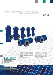
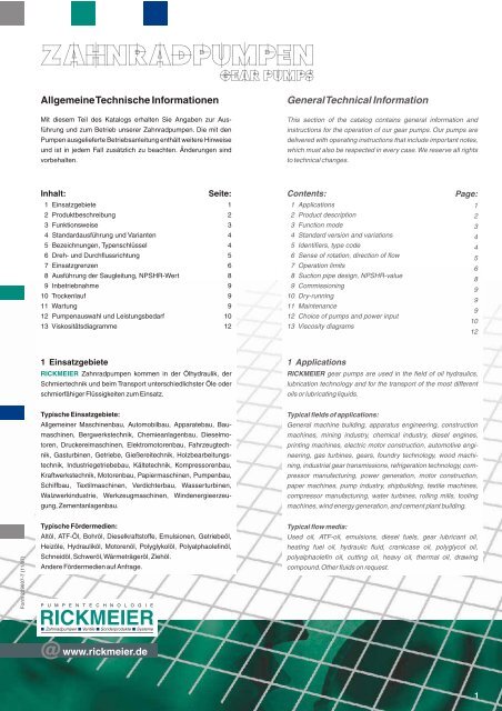
13 Viskositätsdiagramme<br />
Das Viskositäts-Temperatur-Verhalten ist nicht im gesamten<br />
Temperaturbereich genormt; lediglich Teilbereiche und/oder<br />
Minimal- bzw. Maximalwerte sind genormt.<br />
5<br />
10<br />
4<br />
5x10<br />
4<br />
10<br />
3<br />
5x10<br />
3<br />
2x10<br />
3<br />
10<br />
800<br />
600<br />
400<br />
300<br />
200<br />
150<br />
100<br />
80<br />
60<br />
50<br />
40<br />
30<br />
25<br />
10<br />
9<br />
8<br />
11<br />
18<br />
16<br />
14<br />
12<br />
20<br />
7<br />
6<br />
5<br />
4,5<br />
4,0<br />
3,5<br />
3,0<br />
2,7<br />
ISO 8217-DMA ISO 8217-DMB 13 Viscosity diagrams<br />
ISO RM 55<br />
ISO RM 45<br />
ISO RM 35<br />
ISORM25 ISO RM 15<br />
ISO RM 10<br />
-40 -35 -30 -25 -20 -15 -10 -5 0 +5 10 15 20 25 30 40 50 60 70 80 90 100 110 120 130 140<br />
Temperatur temperature [°C]<br />
Abb. 10: Kraft- und Brennstoffe Fig. 10: Liquid fuels and fuel oils<br />
P U M P E N T E C H N O L O G I E<br />
Zahnradpumpen Ventile Sonderprodukte Systeme<br />
The viscosity-temperature-characteristic is not standardized for<br />
the whole temperature range. Only certain areas or max./min.<br />
values are standardized.<br />
DIN ISO 8217-RM...55 (IF700) Schweröl heavy-oil<br />
DIN ISO 8217-RM...45 (IF500) Schweröl heavy-oil<br />
DIN ISO 8217-RM...35 (IF380) Schweröl, Heizöl DIN 51603-S-3 heavy-oil, fuel oil S ref. DIN 51603-S-3<br />
DIN ISO 8217-RM...25 (IF180) Schweröl heavy-oil<br />
DIN ISO 8217-RM...15 (IF80) Schweröl heavy-oil<br />
DIN ISO 8217-RM...10 (IF40) Schweröl heavy-oil<br />
DIN ISO 8217-DMA Schiffsgasöl, Diesel für Lokomotiven Marine Gas Oil (MGO)<br />
Heizöl DIN 51603-EL-1, Kfz-Diesel fuel oil<br />
DIN ISO 8217-DMB Schiffsdieselöl Marine Diesel Oil (MDO)<br />
2<br />
Viskosität viscosity [mm /s]
Form 229607-7 (11/07)<br />
Flüssige Industrie-Schmierstoffe nach DIN 51519 Liquid Industrial Lubricants ref. DIN 51519<br />
2<br />
Viskosität viscosity [mm /s]<br />
5<br />
10<br />
4<br />
5x10<br />
4<br />
10<br />
3<br />
5x10<br />
3<br />
2x10<br />
3<br />
10<br />
800<br />
600<br />
400<br />
300<br />
200<br />
150<br />
100<br />
80<br />
60<br />
50<br />
40<br />
30<br />
25<br />
20<br />
18<br />
16<br />
14<br />
12<br />
11<br />
10<br />
9<br />
8<br />
7<br />
6<br />
5<br />
4,5<br />
4,0<br />
3,5<br />
3,0<br />
2,7<br />
ISOVG 22<br />
ISO VG32<br />
ISO VG 68<br />
ISO VG 46<br />
ISOVG<br />
150<br />
ISOVG<br />
100<br />
P U M P E N T E C H N O L O G I E<br />
ISO VG 320<br />
ISO VG 220<br />
Zahnradpumpen Ventile Sonderprodukte Systeme<br />
ISOVG 1000 ISO VG 680<br />
ISOVG 460<br />
ISOVG1500 -40 -35 -30 -25 -20 -15 -10 -5 0 +5 10 15 20 25 30 40 50 60 70 80 90 100 110 120 130 140<br />
Abb. 11: Industrie-Schmierstoffe nach DIN 51519<br />
Temperatur temperature [°C]<br />
Fig. 11: Industrial Lubricants ref. DIN 51519<br />
13
14<br />
Motorenöle Crankcase oils<br />
2<br />
Viskosität viscosity [mm /s]<br />
5<br />
10<br />
4<br />
5x10<br />
4<br />
10<br />
3<br />
5x10<br />
3<br />
2x10<br />
3<br />
10<br />
800<br />
600<br />
400<br />
300<br />
200<br />
150<br />
100<br />
80<br />
60<br />
50<br />
40<br />
30<br />
25<br />
20<br />
18<br />
16<br />
14<br />
11<br />
10<br />
9<br />
8<br />
12<br />
7<br />
6<br />
5<br />
4,5<br />
4,0<br />
3,5<br />
3,0<br />
2,7<br />
15W-40 20W-40<br />
10W-40 5W-40<br />
SAE 40<br />
SAE30 P U M P E N T E C H N O L O G I E<br />
Zahnradpumpen Ventile Sonderprodukte Systeme<br />
-40 -35 -30 -25 -20 -15 -10 -5 0 +5 10 15 20 25 30 40 50 60 70 80 90 100 110 120 130 140<br />
Temperatur temperature [°C]<br />
Abb. 12: Motorenöle Fig. 12: Crankcase oils<br />
SAE 20<br />
SAE 50
Form 229607-7 (11/07)<br />
Getriebeöle auf Polyglycol-Basis Lubricants for gears polyglycole based<br />
2<br />
Viskosität viscosity [mm /s]<br />
5<br />
10<br />
4<br />
5x10<br />
4<br />
10<br />
3<br />
5x10<br />
3<br />
2x10<br />
3<br />
10<br />
800<br />
600<br />
400<br />
300<br />
200<br />
150<br />
100<br />
80<br />
60<br />
50<br />
40<br />
30<br />
25<br />
20<br />
18<br />
16<br />
14<br />
12<br />
11<br />
10<br />
9<br />
8<br />
7<br />
6<br />
5<br />
4,5<br />
4,0<br />
3,5<br />
3,0<br />
2,7<br />
Temperatur temperature [°C]<br />
ISO VG 220 ISO VG 150<br />
ISO VG460 ISO V G320 ISO VG 1000<br />
ISO VG 680<br />
P U M P E N T E C H N O L O G I E<br />
Abb. 13: Getriebeöle auf Polyglykol-Basis Fig. 13: Lubricants for gears polyglycole based<br />
Zahnradpumpen Ventile Sonderprodukte Systeme<br />
-40 -35 -30 -25 -20 -15 -10 -5 0 +5 10 15 20 25 30 40 50 60 70 80 90 100 110 120 130 140<br />
15
16<br />
Polyalphaolefine Polyalphaolefines<br />
2<br />
Viskosität viscosity [mm /s]<br />
5<br />
10<br />
4<br />
5x10<br />
4<br />
10<br />
3<br />
5x10<br />
3<br />
2x10<br />
3<br />
10<br />
800<br />
600<br />
400<br />
300<br />
200<br />
150<br />
100<br />
80<br />
60<br />
50<br />
40<br />
30<br />
25<br />
20<br />
18<br />
16<br />
14<br />
12<br />
11<br />
10<br />
9<br />
8<br />
7<br />
6<br />
5<br />
4,5<br />
4,0<br />
3,5<br />
3,0<br />
2,7<br />
ISO VG 32<br />
ISO VG 68<br />
ISOVG 150 ISO VG460 ISO VG 320 ISOVG 220<br />
P U M P E N T E C H N O L O G I E<br />
Zahnradpumpen Ventile Sonderprodukte Systeme<br />
ISO VG 1000<br />
-40 -35 -30 -25 -20 -15 -10 -5 0 +5 10 15 20 25 30 40 50 60 70 80 90 100 110 120 130 140<br />
Temperatur temperature [°C]<br />
Abb. 14: Polyalphaolefine Fig. 14: Polyalphaolefines