Technische Hinweise - RICKMEIER Pumpentechnologie
Technische Hinweise - RICKMEIER Pumpentechnologie
Technische Hinweise - RICKMEIER Pumpentechnologie

Sie wollen auch ein ePaper? Erhöhen Sie die Reichweite Ihrer Titel.
YUMPU macht aus Druck-PDFs automatisch weboptimierte ePaper, die Google liebt.
8<br />
8 Ausführung der Saugleitung, NPSHR-Wert<br />
Die Anschlussnennweiten der Pumpen sind so gewählt, dass<br />
diese in den meisten Anwendungsfällen einen technisch und wirtschaftlich<br />
optimalen Richtwert für die Dimensionierung der Saugleitung<br />
darstellen. Für einen einwandfreien Betrieb ist allerdings<br />
letztlich erforderlich, dass der statische Druck unmittelbar am<br />
Eintritt in die Pumpe unter keinen Betriebsbedingungen weniger<br />
als -0,4 bar (entsprechend 0,6 bar absolut) beträgt.<br />
Es empfiehlt sich daher immer, den niedrigsten während des Betriebs<br />
am Pumpeneintritt möglichen statischen Druck unter Berücksichtigung<br />
aller Rohrleitungs- und ggfs. Armaturenwiderstände<br />
genau zu berechnen, bevor die Ausführung der Saugleitung<br />
endgültig festgelegt wird.<br />
Dies insbesondere dann, wenn von den Nennbetriebsbedingungen<br />
für Viskosität, Temperatur und Drehzahl abgewichen<br />
oder in der Saugleitung ein Filter vorgesehen wird, der sich im<br />
Laufe der Zeit zusetzen kann. In diesem Fall ist es ratsam, den<br />
Pumpeneintrittsdruck durch ein Druckmessgerät möglichst nah<br />
vor der Pumpe zu überwachen.<br />
Falls kein Messanschluss in der Saugleitung zur Verfügung steht,<br />
kann hierzu bei Pumpen mit Druckbegrenzungsventil auch der<br />
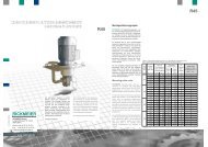
der Saugseite zugewandte Manometeranschluss (siehe Abb. 1<br />
Pos. 8) verwendet werden. Im übrigen muss die Saugleitung<br />
absolut dicht sein, damit keine Luft angesaugt wird. Starke<br />
Geräuschentwicklung weist auf das Ansaugen von Luft oder das<br />
Vorhandensein von Kavitation infolge zu niedrigen Pumpeneintrittsdrucks<br />
hin.<br />
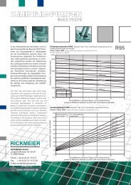
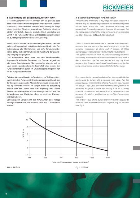
Der häufig zum Vergleich mit dem NPSHA-Wert einer Anlage<br />
benötigte NPSHR-Wert der Pumpen kann Abb. 7 entnommen<br />
werden.<br />
NPSHR [m]<br />
11<br />
10<br />
9<br />
8<br />
7<br />
6<br />
Abb. 7: NPSHR Fig. 7: NPSHR<br />
8 Suction pipe design, NPSHR-value<br />
P U M P E N T E C H N O L O G I E<br />
Zahnradpumpen Ventile Sonderprodukte Systeme<br />
The connecting dimensions of the pumps have been selected in a<br />
way that they will represent a guideline for the dimensioning of the<br />
suction pipe, which has been optimized technically and<br />
economically. For a perfect operation, however, it is necessary that<br />
the static pressure direct at the entry of the pump, on no operating<br />
condition, falls below -0,4 bar (0,6 bar absolute).<br />
Thus it is always recommendable to calculate the lowest static<br />
pressure that may occur at the pump’s entry side during the<br />
operation considering all piping and, if needed, all fitting<br />
resistances prior to finalizing the execution of the suction pipe.<br />
This applies in particular, when the nominal operating conditions<br />
for viscosity, temperature and speed are deviated from, or, when a<br />
filter in the suction pipe has been planned that may clog in the<br />
course of time. In such a case it would be advisable to monitor the<br />
pump entry pressure as close as possible in front of the pump.<br />
If no connection for measuring devices has been provided in the<br />
suction pipe for pumps with a pressure relief valve, then the<br />
pressure gauge connection that is facing the suction side may also<br />
be used (p.r.t. Fig. 1, pos. 8). Furthermore the suction pipe must be<br />
absolutely leakproof to avoid any sucking in of air. A strong<br />
formation of noise is an indication that air is sucked in or for the<br />
presence of cavitation resulting from an insufficient pump entry<br />
pressure.<br />
The NPSHR-value of the pumps that is frequently required to<br />
compare it with the NPSHA-value of a system may be obtained<br />
from Fig. 7.<br />
5<br />
600 700 800 900 1000 1100<br />
3<br />
Dichte des Fördermediums density of fluid [kg/m ]