Betriebsanleitung Sicherheitsschalter STA...AS1 - EUCHNER GmbH ...
Betriebsanleitung Sicherheitsschalter STA...AS1 - EUCHNER GmbH ...
Betriebsanleitung Sicherheitsschalter STA...AS1 - EUCHNER GmbH ...

Sie wollen auch ein ePaper? Erhöhen Sie die Reichweite Ihrer Titel.
YUMPU macht aus Druck-PDFs automatisch weboptimierte ePaper, die Google liebt.
<strong>Betriebsanleitung</strong> <strong>Sicherheitsschalter</strong> <strong>STA</strong>...<strong>AS1</strong><br />
Bestimmungsgemäßer Gebrauch<br />
<strong>EUCHNER</strong> <strong>Sicherheitsschalter</strong> der Baureihe <strong>STA</strong>...AS<br />
werden als Slave am Sicherheitsbus AS-Interface<br />
Safety at Work betrieben und arbeiten als elektromagnetische<br />
Verriegelungseinrichtungen mit Zuhaltung.<br />
In Verbindung mit einer trennenden Schutzeinrichtung<br />
und der Maschinensteuerung verhindert dieses<br />
Sicherheitsbauteil, dass die Schutzeinrichtung geöffnet<br />
werden kann, solange eine gefährliche Maschinenbewegungen<br />
ausgeführt wird.<br />
Für die Steuerung bedeutet dies, dass<br />
� Einschaltbefehle, die gefährdende Zustände hervorrufen,<br />
erst dann wirksam werden dürfen, wenn die<br />
Schutzeinrichtung in Schutzstellung und die Zuhaltung<br />
in Sperrstellung ist.<br />
Die Sperrstellung der Zuhaltung darf erst dann aufgehoben<br />
werden, wenn gefährdende Zustände<br />
beendet sind.<br />
Vor dem Einsatz von <strong>Sicherheitsschalter</strong>n ist eine Risikobeurteilung<br />
an der Maschine durchzuführen z. B. nach<br />
� EN ISO 13849, Sicherheit von Maschinen -<br />
Sicherheitsbezogene Teile von Steuerungen<br />
� EN 12100-1, Sicherheit von Maschinen - Allgemeine<br />
Gestaltungsleitsätze - Risikobeurteilung und<br />
Risikominderung<br />
� IEC 62061, Sicherheit von Maschinen - Funktionale<br />
Sicherheit sicherheitsbezogener elektrischer, elektronischer<br />
und programmierbarer elektronischer<br />
Steuerungssysteme.<br />
Zum bestimmungsgemäßen Gebrauch gehört das<br />
Einhalten der einschlägigen Anforderungen für den<br />
Einbau und Betrieb, z. B.<br />
� EN ISO 13849, Sicherheit von Maschinen -<br />
Sicherheitsbezogene Teile von Steuerungen<br />
� EN 1088, Verriegelungseinrichtungen in Verbindung<br />
mit trennenden Schutzeinrichtungen<br />
� EN 60 204-1, Elektrische Ausrüstung von Maschinen.<br />
Wichtig:<br />
� Der Anwender trägt die Verantwortung für die sichere<br />
Einbindung des Geräts in ein sicheres Gesamtsystem.<br />
Dazu muss das Gesamtsystem z. B. nach<br />
EN ISO 13849-2 validiert werden.<br />
� Wird zur Validierung das vereinfachte Verfahren nach<br />
Abschnitt 6.3 EN ISO 13849-1:2008 benutzt, reduziert<br />
sich möglicherweise der Performance Level<br />
(PL), wenn mehrere Geräte hintereinander geschaltet<br />
werden.<br />
� Liegt dem Produkt ein Datenblatt bei, gelten die<br />
Angaben des Datenblatts, falls diese von der<br />
<strong>Betriebsanleitung</strong> abweichen.<br />
Sicherheitshinweise<br />
<strong>Sicherheitsschalter</strong> erfüllen eine Personenschutz-<br />
Funktion. Unsachgemäßer Einbau oder Manipulationen<br />
können zu schweren Verletzungen von Personen<br />
führen.<br />
Sicherheitsbauteile dürfen nicht umgangen (Kontakte<br />
überbrückt), weggedreht, entfernt oder auf<br />
andere Weise unwirksam gemacht werden.<br />
Beachten Sie hierzu insbesondere die Maßnahmen<br />
zur Verringerung der Umgehungsmöglichkeiten nach<br />
EN 1088:1995.A2:2008, Abschn. 5.7.<br />
Der Schaltvorgang darf nur durch speziell dafür<br />
vorgesehene Betätiger ausgelöst werden, die unlösbar<br />
mit der Schutzeinrichtung verbunden sind.<br />
Betätiger S Standard, Betätiger L mit Einführtrichter.<br />
Ein komplettes sicherheitsgerichtetes System<br />
besteht in der Regel aus mehreren Meldegeräten,<br />
Sensoren, Auswerteeinheiten und Konzepten für<br />
sichere Abschaltungen. Der Hersteller einer Maschine<br />
oder Anlage ist für die korrekte und sichere<br />
Gesamtfunktion verantwortlich.<br />
Alle Sicherheitshinweise und Vorgaben der <strong>Betriebsanleitung</strong><br />
des verwendeten AS-Interface<br />
Sicherheitsmonitors müssen eingehalten werden.<br />
Montage, elektrischer Anschluss und Inbetriebnahme<br />
ausschließlich durch autorisiertes Fachpersonal.<br />
Funktion<br />
<strong>EUCHNER</strong> <strong>Sicherheitsschalter</strong> der Baureihe <strong>STA</strong>...AS<br />
besitzen eine Slave-Anschaltung an den Sicherheitsbus<br />
AS-Interface Safety at Work. Sie ermöglichen das<br />
Zuhalten von trennenden beweglichen Schutzeinrichtungen.<br />
Die Stellungsüberwachung der Schutzeinrichtung und<br />
die Verriegelungsüberwachung erfolgt dabei über zwei<br />
getrennte Schaltelemente (Türüberwachungskontakt<br />
SK und Magnetüberwachungskontakt ÜK).<br />
Bei geschlossener Schutzeinrichtung und wirksamer<br />
Zuhaltung sendet jeder <strong>STA</strong>...AS über den AS-Interface<br />
Bus eine schalterspezifische unverwechselbare Sicherheits-Codefolge<br />
mit 8x4 bit. Diese Codefolge wird<br />
von einem AS-Interface Sicherheitsmonitor ausgewertet.<br />
Der Zwangsöffner SK zur Türüberwachung wird<br />
über die AS-Interface Eingangsbits D0 und D1 abgebildet.<br />
Der Magnetüberwachungskontakt ÜK über die<br />
AS-Interface Eingangsbits D2 und D3.<br />
Der <strong>Sicherheitsschalter</strong> muss im AS-Interface<br />
Sicherheitsmonitor entsprechend konfiguriert werden<br />
(siehe <strong>Betriebsanleitung</strong> des verwendeten AS-Interface<br />
Sicherheitsmonitors und Zustandstabelle).<br />
Ausführung Betätiger<br />
Betätiger S für <strong>Sicherheitsschalter</strong> <strong>STA</strong> ohne Einführtrichter.<br />
Betätiger L für <strong>Sicherheitsschalter</strong> <strong>STA</strong> mit Einführtrichter.<br />
Ausführung <strong>STA</strong>3...AS<br />
(Zuhaltung durch Federkraft)<br />
Zum Personenschutz vor nachlaufenden gefährlichen<br />
Bewegungen, muss zusätzlich die schwarze<br />
AS-Interface Leitung (Hilfsenergie), die zur<br />
AS-Interface Verteilerbox führt, an die der Schalter<br />
angeschlossen ist, über einen Stillstandswächter<br />
oder über die sichere Einschaltverzögerung<br />
eines zweikanaligen AS-Interface<br />
Sicherheitsmonitors geschaltet werden (z.B. Türzuhaltung<br />
über Verzögerungszeit).<br />
Der Zuhaltebolzen wird durch Federkraft in Sperrstellung<br />
gehalten und durch elektromagnetische Betätigung<br />
entsperrt. Die federkraftverriegelte Zuhaltung arbeitet<br />
nach dem Ruhestromprinzip. Bei Unterbrechung der<br />
Spannungsversorgung des Magneten kann die Schutzeinrichtung<br />
nicht unmittelbar geöffnet werden.<br />
Für den Prozessschutz kann der Zuhaltemagnet per<br />
Software über das AS-Interface Ausgangsbit D0 geschaltet<br />
werden.<br />
Ausführung <strong>STA</strong>4...AS<br />
(Zuhaltung durch Magnetkraft)<br />
Anwendung nur in Sonderfällen nach strenger<br />
Bewertung des Unfallrisikos!<br />
Bei Unterbrechung der Spannungsversorgung<br />
des Magneten kann die Schutzeinrichtung unmittelbar<br />
geöffnet werden!<br />
Der Zuhaltebolzen wird elektromagnetisch in Sperrstellung<br />
gehalten und durch Federkraft entsperrt. Die<br />
Zuhaltung arbeitet nach dem Arbeitsstromprinzip.<br />
Für den Prozessschutz kann der Zuhaltemagnet per<br />
Software über das AS-Interface Ausgangsbit D0 geschaltet<br />
werden.<br />
� Schutzeinrichtung schließen und Zuhaltung aktivieren<br />
Durch Einführen des Betätigers in den <strong>Sicherheitsschalter</strong><br />
wird der Zuhaltebolzen freigegeben.<br />
<strong>STA</strong>3...AS: Der Zuhaltebolzen geht federkraftbetätigt<br />
in Sperrstellung.<br />
<strong>STA</strong>4...AS: Der Zuhaltebolzen geht durch Anlegen der<br />
Magnetbetriebsspannung in Sperrstellung.<br />
Die Sicherheitskontakte werden geschlossen.<br />
Über die AS-Interface Eingangsbits D0 bis D3 wird<br />
die vollständige Sicherheits-Codefolge (8 x 4 Bit) gesendet.<br />
� Zuhaltung deaktivieren, Schutzeinrichtung öffnen<br />
<strong>STA</strong>3...AS: Durch Anlegen der Magnetbetriebsspannung<br />
und Freigabe über das AS-Interface Ausgangsbit<br />
D0 wird die Zuhaltung deaktiviert.<br />
Der Magnetüberwachungskontakt ÜK wird geöffnet.<br />
Über die AS-Interface Eingangsbits D2 und D3 wird<br />
in jedem Buszyklus das Wertepaar 0, 0 gesendet.<br />
Der Betätiger kann herausgezogen werden.<br />
Durch Herausziehen des Betätigers wird der Türüberwachungskontakt<br />
SK zwangsgeöffnet und die Zuhaltung<br />
wird in dieser Stellung blockiert (Fehlschließsicherung).<br />
Über die AS-Interface Eingangsbits D0 bis<br />
D3 werden kontinuierlich die Werte 0, 0, 0, 0 gesendet.<br />
<strong>STA</strong>4...AS: Durch der Magnetbetriebsspannung und<br />
Freigabe über das AS-Interface Ausgangsbit D0 wird<br />
die Zuhaltung deaktiviert. Der Magnetüberwachungskontakt<br />
ÜK wird geöffnet. Über die AS-Interface Eingangsbits<br />
D2 und D3 wird in jedem Buszyklus das<br />
Wertepaar 0, 0 gesendet.<br />
Der Betätiger kann herausgezogen werden.<br />
Durch Herausziehen des Betätigers wird der Türüberwachungskontakt<br />
SK zwangsgeöffnet und die Zuhaltung<br />
wird in dieser Stellung blockiert (Fehlschließsicherung).<br />
Über die AS-Interface Eingangsbits D0 bis<br />
D3 werden kontinuierlich die Werte 0, 0, 0, 0 gesendet.<br />
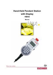
Hilfsentriegelung<br />
Bei Funktionsstörungen kann mit der Hilfsentriegelung<br />
die Zuhaltung, unabhängig vom Zustand des Elektromagneten,<br />
entsperrt werden (siehe Bild 3).<br />
� Sicherungsschraube herausdrehen.<br />
� Hilfsentriegelung mit Schraubendreher in Pfeilrichtung<br />
um ca. 180° drehen.<br />
Die Hilfsentriegelung muss nach Gebrauch rückgestellt<br />
und versiegelt werden (z.B. durch Sicherungslack).<br />
Montage<br />
<strong>Sicherheitsschalter</strong> und Betätiger dürfen nicht<br />
als Anschlag verwendet werden.<br />
Nur in zusammengebautem Zustand befestigen!<br />
Bei Umgebungstemperaturen größer 55 °C muss<br />
der Schalter gegen Berührung mit brennbarem<br />
Material oder gegen versehentliches Berühren<br />
durch Personen geschützt werden.<br />
<strong>Sicherheitsschalter</strong> so anbauen, dass<br />
� er für Bedienpersonal bei geöffneter Schutzeinrichtung<br />
schwer zugänglich ist<br />
� Bedienung der Hilfsentriegelung dennoch möglich<br />
ist<br />
� Adressprogrammierung, Kontrolle und Austausch<br />
durch Fachpersonal möglich ist.<br />
� Betätiger in Betätigungskopf einführen.<br />
� <strong>Sicherheitsschalter</strong> formschlüssig anbauen.<br />
� Betätiger dauerhaft und unlösbar mit der Schutzeinrichtung<br />
verbinden, z.B. durch die beiliegenden<br />
Einwegschrauben, nieten oder schweißen.<br />
� Zusätzlichen Anschlag für beweglichen Teil der<br />
Schutzeinrichtung anbringen.<br />
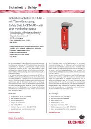
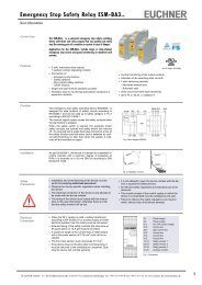
Umstellen der Betätigungsrichtung<br />
C<br />
B<br />
Bild 1: Umstellen der Betätigungsrichtung<br />
� Betätiger in Betätigungskopf einführen.<br />
� Schrauben am Betätigungskopf lösen.<br />
� Gewünschte Richtung einstellen.<br />
� Schrauben mit 0,6 Nm anziehen.<br />
� Nicht benutzte Betätigungsschlitze mit beiliegenden<br />
Schlitzabdeckungen verschließen.<br />
D<br />
A
<strong>Betriebsanleitung</strong> <strong>Sicherheitsschalter</strong> <strong>STA</strong>...<strong>AS1</strong><br />
Schutz vor Umgebungseinflüssen<br />
Voraussetzung für eine dauerhafte und einwandfreie<br />
Sicherheitsfunktion ist der Schutz des Betätigungskopfes<br />
vor eindringenden Fremdkörpern wie Spänen,<br />
Sand, Strahlmitteln usw.<br />
Elektrischer Anschluss<br />
Für den Einsatz und die Verwendung gemäß den Anforderungen<br />
von (UL) muss ein Trenntransformator<br />
oder eine Spannungsversorgung mit sekundärem Überstromschutz<br />
(3 A) verwendet werden.<br />
Der Anschluss des <strong>Sicherheitsschalter</strong>s an das Bussystem<br />
erfolgt mit einem 4-poligen Anschlusskabel<br />
mit M12-Steckverbinder über eine passive AS-Interface<br />
Verteilerbox mit gelbem und schwarzem<br />
AS-Interface Kabel.<br />
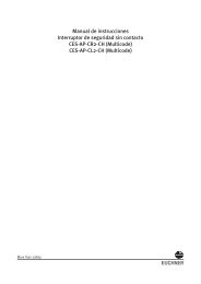
1 AS-Interface +<br />
2 Hilfsspannung 0 V<br />
3 AS-Interface -<br />
4 Hilfsspannung 24 V<br />
Bild 2: Anschlussbelegung M12-Steckverbinder<br />
Inbetriebnahme<br />
Ansicht Steckverbinder<br />
<strong>Sicherheitsschalter</strong><br />
4 3<br />
1 2<br />
� Einstellen der AS-Interface Adresse<br />
Das Einstellen der Adresse ist vor oder nach der<br />
Montage möglich.<br />
Die AS-Interface Adresse des <strong>Sicherheitsschalter</strong>s<br />
wird mit einem AS-Interface Programmiergerät eingestellt.<br />
Adresse 1 bis 31 ist gültig.<br />
Dazu wird das Programmiergerät mit einem<br />
Programmierkabel an den M12-Steckverbinder des<br />
<strong>Sicherheitsschalter</strong>s angeschlossen.<br />
Auslieferungszustand ist die Adresse 0 (im Betrieb<br />
leuchtet die AS-Interface LED Fault !).<br />
� Konfiguration im AS-Interface Sicherheitsmonitor<br />
(siehe <strong>Betriebsanleitung</strong> AS-Interface Sicherheitsmonitor<br />
und Zustandstabelle)<br />
Der <strong>Sicherheitsschalter</strong> wird im AS-Interface<br />
Sicherheitsmonitor mit der eingestellten AS-Interface<br />
Adresse z.B. wie folgt konfiguriert:<br />
� Zweikanalig abhängig<br />
� Synchronisationszeit = unendlich ∞<br />
In dieser Betriebsart ist zur Durchführung der Anlauftestung<br />
vor jedem Wiederanlauf das Öffnen der<br />
Schutzeinrichtung erforderlich.<br />
� Zweikanalig unabhängig<br />
Die Zuhaltung wird über die Ansteuerung des Ausgang<br />
D0 geöffnet bzw. geschlossen. Bei offener Zuhaltung<br />
schaltet der Sicherheitskreis ab. Die Tür muss<br />
nicht geöffnet werden. Die Sicherheit ist wieder gegeben,<br />
wenn die Zuhaltung geschlossen wird.<br />
Die Zweikanaligkeit und der Türkontakt werden in<br />
dieser Konfiguration nicht getestet. Für eine Testung<br />
müssen außerhalb des Monitors zusätzliche Maßnahmen<br />
ergriffen werden.<br />
Für den erweiterten Monitor SFM-B02 ist folgende<br />
Konfiguration möglich:<br />
� Zweikanalig bedingt abhängig<br />
� Unabhängig: In-1<br />
Die Zuhaltung wird über die Ansteuerung des Ausgang<br />
D0 geöffnet bzw. geschlossen. Bei offener Zuhaltung<br />
schaltet der Sicherheitskreis ab. Die Tür muss<br />
nicht geöffnet werden. Die Sicherheit ist wieder gegeben,<br />
wenn die Zuhaltung geschlossen wird.<br />
Eine Fehlfunktion des Schalters wird überwacht, der<br />
Türkontakt (SK) darf nicht vor dem Zuhaltekontakt<br />
(ÜK) schalten.<br />
Wird beim federkraftverriegelten <strong>Sicherheitsschalter</strong><br />
<strong>STA</strong>3..AS in der Betriebsart Türzuhaltung über<br />
Verzögerungszeit über den zweiten Freischaltekontakt<br />
eines zweikanaligen Sicherheitsmonitors und<br />
eine SPS der Zuhaltemagnet eingeschaltet (entsperrt),<br />
muss folgendes beachtet werden:<br />
� Das Abschalten des Zuhaltemagneten durch den<br />
Monitor allein ist nicht möglich.<br />
Die Steuerung (SPS) muss deshalb über den<br />
AS-Interface Ausgang D0 = 0 den Zuhaltemagnet<br />
in die Sperrstellung abschalten, um die Einschaltbedingungen<br />
für den ersten Freigabekreis wieder<br />
herzustellen.<br />
� Damit der Zuhaltemagnet durch den zweiten<br />
Sicherheitsausgang des Monitors entsperrt werden<br />
kann, muss der AS-Interface Ausgang mit D0 = 1<br />
eingeschaltet werden.<br />
� Meldesignale (nicht sicherheitsrelevant)<br />
Der Zustand des Türmeldekontaktes SK und des<br />
Magnetüberwachungskontaktes ÜK kann auch durch<br />
die Steuerung (SPS) abgefragt werden (siehe <strong>Betriebsanleitung</strong><br />
AS-Interface Sicherheitsmonitor).<br />
� LED-Anzeigen<br />
Der AS-Interface Buszustand wird über zwei LEDs<br />
(Power, Fault) angezeigt.<br />
Zwei zusätzliche LEDs können über den AS-Inter-face<br />
Bus, z.B. zur Anzeige der Meldesignale, geschaltet<br />
werden (siehe Meldesignale und technische Daten).<br />
Funktionskontrolle<br />
Warnung! Tödliche Verletzung durch Fehler bei<br />
der Installation und Funktionskontrolle.<br />
Stellen Sie vor der Funktionskontrolle sicher, dass<br />
sich keine Personen im Gefahrenbereich befinden.<br />
Beachten Sie die geltenden Vorschriften zur<br />
Unfallverhütung.<br />
Nach der Installation und jedem Fehler muss eine<br />
vollständige Kontrolle der Sicherheitsfunktion durchgeführt<br />
werden. Gehen Sie dabei folgendermaßen vor:<br />
� Mechanische Funktionsprüfung<br />
Der Betätiger muss sich leicht in den Betätigungskopf<br />
einführen lassen. Zur Überprüfung Schutzeinrichtung<br />
mehrmals schließen.<br />
� Elektrische Funktionsprüfung<br />
1. Betriebsspannung einschalten.<br />
2. Alle Schutzeinrichtungen schließen.<br />
Bei Zuhaltung durch Magnetkraft � Zuhaltung<br />
aktivieren.<br />
� Die Maschine darf nicht selbständig anlaufen.<br />
� Die Schutzeinrichtung darf sich nicht öffnen lassen.<br />
3. Betrieb in der Steuerung freigeben.<br />
� Die Zuhaltung darf sich nicht deaktivieren lassen,<br />
solange der Betrieb freigegeben ist.<br />
4. Betrieb in der Steuerung abschalten und Zuhaltung<br />
deaktivieren.<br />
� Die Schutzeinrichtung muss so lange zugehalten<br />
bleiben, bis kein Verletzungsrisiko mehr besteht.<br />
� Die Maschine darf sich nicht starten lassen, solange<br />
die Zuhaltung deaktiviert ist.<br />
Wiederholen Sie die Schritte 2 - 4 für jede Schutzeinrichtung<br />
einzeln.<br />
Kontrolle und Wartung<br />
Bei Beschädigung oder Verschleiß muss der gesamte<br />
Schalter mit Betätiger ausgetauscht werden.<br />
Der Austausch von Einzelteilen oder Baugruppen,<br />
insbesondere des Betätigungskopfes, ist<br />
unzulässig!<br />
Hinweis: Das Baujahr ist in der unteren, rechten Ecke<br />
des Typenschilds ersichtlich.<br />
Wartungsarbeiten sind nicht erforderlich. Um eine<br />
einwandfreie und dauerhafte Funktion zu gewährleisten,<br />
sind regelmäßige Kontrollen erforderlich auf<br />
� einwandfreie Schaltfunktion<br />
� sichere Befestigung der Bauteile<br />
� Ablagerungen und Verschleiß<br />
� gelockerte Steckverbinder.<br />
Haftungsausschluss bei<br />
� nicht bestimmungsgemäßem Gebrauch<br />
� Nichteinhalten der Sicherheitshinweise<br />
� Anbau und elektrischem Anschluss durch nicht autorisiertes<br />
Fachpersonal<br />
� nicht durchgeführten Funktionskontrollen.<br />
EG-Konformitätserklärung<br />
Der nachstehende Hersteller erklärt hiermit, dass das<br />
Produkt in Übereinstimmung ist mit den Bestimmungen<br />
der nachfolgend aufgeführten Richtlinie(n) und<br />
dass die jeweiligen Normen zur Anwendung gelangt<br />
sind.<br />
<strong>EUCHNER</strong> <strong>GmbH</strong> + Co. KG<br />
Kohlhammerstraße 16<br />
70771 Leinfelden-Echterdingen, Deutschland<br />
Angewendete Richtlinien:<br />
� Maschinenrichtlinie 2006/42/EG<br />
Angewendete Normen:<br />
� EN 60947-5-1:2004 + Cor.:2005 + A1:2009<br />
� EN 1088:1995+A2:2008<br />
Leinfelden, Juli 2010<br />
Dipl.-Ing. Michael Euchner<br />
Geschäftsführer<br />
Duc Binh Nguyen<br />
Dokumentationsbevollmächtigter<br />
Die unterzeichnete EG-Konformitätserklärung ist dem<br />
Produkt beigelegt.<br />
<strong>EUCHNER</strong> <strong>GmbH</strong> + Co. KG Kohlhammerstraße 16 D-70771 Leinfelden-Echterdingen Tel. +49/711/75 97-0 Fax +49/711/75 33 16 www.euchner.de info@euchner.de<br />
Technische Änderungen vorbehalten, alle Angaben ohne Gewähr. © <strong>EUCHNER</strong> <strong>GmbH</strong> + Co. KG 099108-03-11/11 (Originalbetriebsanleitung)
<strong>Betriebsanleitung</strong> <strong>Sicherheitsschalter</strong> <strong>STA</strong>...<strong>AS1</strong><br />
Technische Daten<br />
(F = Zh F Parameter Wert<br />
Gehäusewerkstoff Leichtmetall-Druckguss<br />
Schutzart nach IEC 529 IP 67, Gegenstecker gesteckt<br />
Mech. Lebensdauer 1x10<br />
max<br />
) = 2300 N<br />
1,3<br />
6 Schaltspiele<br />
Umgebungstemperatur -20...+55°C<br />
Einbaulage beliebig<br />
Anfahrgeschwindigkeit max. 20 m/min<br />
Betätigungskraft max. 35 N<br />
Auszugskraft 30 N (nicht zugehalten)<br />
Rückhaltekraft 20 N<br />
Zuhaltekraft Fmax<br />
Betätiger mit Tülle<br />
Betätiger gerade 3000 N<br />
Betätiger abgewinkelt 1500 N<br />
Zuhaltekraft FZh nach<br />
Prüfgrundsatz GS-ET-19<br />
Betätigungshäufigkeit 7000/h<br />
Masse ca. 0,5 kg<br />
Schaltprinzip SK, ÜK Zwangsöffner, Schleichschaltglied<br />
EMV-Schutzanforderungen<br />
Zuhaltemagnet<br />
gemäß EN 50295 (AS-Interface<br />
Norm) und IEC 62026<br />
Magnetbetriebsspannung DC 24 V +10%/-15% 8 W<br />
(Hilfsspannung auf schwarzer Netzgerät mit sicherer Trennung<br />
AS-Interface Leitung) (IEC 60742, PELV)<br />
Magnetbetriebsstrom 300 mA<br />
Einschaltdauer ED 100 %<br />
Anschlussart<br />
Mindestweg und Nachlauf<br />
M12-Steckverbinder<br />
Anfahrrichtung Betätiger S Betätiger L für<br />
Standard Einführtrichter<br />
horizontal (h) + vertikal (v) 24,5 + 5 28,5 + 5<br />
AS-Interface Daten gemäß EA-Code: 7<br />
AS-Interface Spezifikation 2.1 ID-Code: B<br />
Betriebsspannung AS-Interface DC 22,5 ... 31,6 V<br />
Gesamtstromaufnahme max. 45 mA<br />
Gültige AS-Interface Adressen 1 - 31<br />
AS-Interface Eingänge nach AS-Interface Safety at Work<br />
Türüberwachungskontakt SK<br />
Magnetüberwachungs-<br />
D0, D1<br />
kontakt ÜK<br />
AS-Interface Ausgänge<br />
D2, D3<br />
D0 Zuhaltemagnet, 1 = Magnet bestromt<br />
D1 LED rot, 1 = LED ein<br />
D2 LED grün, 1 = LED ein<br />
AS-Interface LED Power grün, AS-Interface Spannung liegt an<br />
AS-Interface LED Fault rot, Offline Phase oder Adresse 0<br />
Zuverlässigkeitswerte nach EN ISO 13849-1<br />
B10d<br />
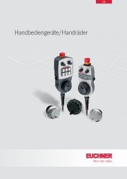
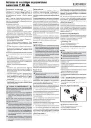
1,2 x 10⁷ Bild 3: Maßzeichnungen<br />
26<br />
12<br />
Radiusbetätiger S-OU-SN<br />
R > 200<br />
24,5 +5<br />
Radiusbetätiger S-LR-SN<br />
Bild 4: Minimale Türradien<br />
190<br />
22<br />
13,5<br />
4<br />
Verschlussschraube<br />
M20 x 1,5<br />
35,5<br />
R>200<br />
20<br />
30<br />
16,3<br />
<br />
<br />
35,5<br />
M20x1,5 (3x)<br />
16<br />
41,5<br />
144<br />
v<br />
GN RD<br />
Power Fault<br />
Betätiger-Typ Türradius min. [mm]<br />
Betaetiger-S-G... 300<br />
Betaetiger-S-W... 300<br />
RADIUSBETAETIGER-S-OU... 200<br />
RADIUSBETAETIGER-S-LR... 200<br />
9<br />
4<br />
30<br />
<br />
h<br />
30<br />
16<br />
Radiusbetätiger S-OU-LN<br />
für Einführtrichter<br />
R > 200<br />
4<br />
28,5 +5<br />
0,5<br />
∅ 5,3 (4x)<br />
für M5x35 mm<br />
ISO 1207<br />
ISO 4762<br />
HilfsentriegelungSicherungsschraube<br />
0,5<br />
35,5<br />
20<br />
Radiusbetätiger S-LR-LN<br />
für Einführtrichter<br />
R>200
<strong>Betriebsanleitung</strong> <strong>Sicherheitsschalter</strong> <strong>STA</strong>...<strong>AS1</strong><br />
Zustandstabelle<br />
Programmierung Zustand D0, D1 D2, D3 Monitordiagnose<br />
Schutzeinrichtung geschlossen, Zuhaltung aktiv Codefolge Grün<br />
Zuhaltung geöffnet Halbfolge 00 Gelb blinkend<br />
2-kanalig<br />
bedingt abhängig<br />
Ungültiger Zustand<br />
(Schutzeinrichtung offen, Zuhaltung aktiv)<br />
00 Halbfolge<br />
Rot blinkend<br />
(Überwachung des ungültigen Zustands)<br />
Schutzeinrichtung offen 00 00 Rot<br />
Adresse 0 oder Kommunikation gestört – Grau<br />
Schutzeinrichtung geschlossen, Zuhaltung aktiv Codefolge Grün<br />
Zuhaltung geöffnet Halbfolge 00 Rot<br />
2-kanalig<br />
unabhängig<br />
Ungültiger Zustand<br />
(Schutzeinrichtung offen, Zuhaltung aktiv)<br />
00 Halbfolge<br />
Rot<br />
(Überwachung des ungültigen Zustands)<br />
2-kanalig<br />
abhängig<br />
Schutzeinrichtung offen 00 00 Rot<br />
Adresse 0 oder Kommunikation gestört – Grau<br />
Schutzeinrichtung geschlossen, Zuhaltung aktiv Codefolge<br />
Grün, wenn Schutzeinrichtung zuvor geöffnet war<br />
oder nach Anlauf gelb blinkend, wenn nur<br />
Zuhaltung geöffnet war.<br />
Synchronisationszeit<br />
unendlich ∞ Ungültiger Zustand<br />
(Schutzeinrichtung offen, Zuhaltung aktiv)<br />
Gelb blinkend, wenn Schutzeinrichtung<br />
Zuhaltung geöffnet Halbfolge 00 zuvor geschlossen war.<br />
Rot, wenn Schutzeinrichtung zuvor geöffnet war.<br />
Gelb blinkend, wenn Schutzeinrichtung<br />
00 Halbfolge zuvor geschlossen war.<br />
Rot, wenn Schutzeinrichtung zuvor geöffnet war.<br />
Schutzeinrichtung offen 00 00 Rot<br />
Adresse 0 oder Kommunikation gestört – Grau<br />
<strong>EUCHNER</strong> <strong>GmbH</strong> + Co. KG Kohlhammerstraße 16 D-70771 Leinfelden-Echterdingen Tel. +49/711/75 97-0 Fax +49/711/75 33 16 www.euchner.de info@euchner.de
Operating Instructions Safety Switches <strong>STA</strong>...<strong>AS1</strong><br />
Correct use<br />
<strong>EUCHNER</strong> safety switches series <strong>STA</strong>...AS are<br />
operated as a slave on the safety bus AS-Interface<br />
Safety at Work and function as electromagnetic interlock<br />
devices with guard locking.<br />
In combination with a safety guard and the machine<br />
control, this safety component prevents the safety<br />
guard from being opened while a dangerous machine<br />
movement is being performed.<br />
For the control system, this means that<br />
� starting commands which cause hazardous<br />
situations must become active only when the safety<br />
guard is in protective position and the guard locking<br />
is in locked position.<br />
The locked position of the guard locking must be<br />
released only when the hazardous situation is no<br />
longer present.<br />
Before safety switches are used, a risk assessment<br />
must be performed on the machine, e.g., in<br />
accordance with<br />
� EN ISO 13849, Safety of machinery - Safety-related<br />
parts of control systems<br />
� EN 12100-1, Safety of machinery - General<br />
principles for design - Risk assessment and risk<br />
reduction<br />
� IEC 62061, Safety of machinery - Functional safety<br />
of safety-related electrical, electronic and<br />
programmable electronic control systems.<br />
Correct use includes compliance with the relevant<br />
requirements for installation and operation, e.g.<br />
� EN ISO 13849, Safety of machinery - Safety-related<br />
parts of control systems<br />
� EN 1088, Safety of machinery. Interlocking devices<br />
associated with guards. Principles for design and<br />
selection<br />
� EN 60 204-1, Electrical equipment of machines.<br />
Important:<br />
� The user is responsible for safe integration of the<br />
device in a safe overall system. For this purpose,<br />
the overall system must be validated, e.g. in<br />
accordance with EN ISO 13849-2.<br />
� If the simplified method according to section 6.3<br />
EN ISO 13849-1:2008 is used for validation, the<br />
Performance Level (PL) may be reduced if several<br />
devices are connected one after the other.<br />
� If a product data sheet is included with the product,<br />
the information on the data sheet applies in case of<br />
discrepancies with the operating instructions.<br />
Safety precautions<br />
Safety switches fulfill a personal protection function.<br />
Incorrect installation or tampering can lead to severe<br />
injuries to personnel.<br />
Safety components must not be bypassed<br />
(bridging of contacts), turned away, removed or<br />
otherwise rendered ineffective.<br />
On this topic pay attention in particular to the<br />
measures for reducing the possibility of bypassing<br />
according to EN 1088:1995.A2:2008, sec. 5.7.<br />
The switching operation may only be triggered<br />
by actuators specially provided for this purpose<br />
which are permanently connected to the<br />
protective guard. Actuator S standard, actuator<br />
L with insertion funnel.<br />
A complete safety-oriented system generally<br />
consists of several signaling devices, sensors,<br />
evaluation units and concepts for safe shutdown.<br />
The manufacturer of a machine or installation is<br />
responsible for correct and safe overall function.<br />
All safety instructions and requirements stated<br />
in the Operating Instructions of the AS-Interface<br />
safety monitor used must be observed.<br />
Mounting, electrical connection and setup only<br />
by authorized personnel.<br />
Function<br />
<strong>EUCHNER</strong> safety switches series <strong>STA</strong>...AS feature a<br />
slave connection to the safety bus AS-Interface Safety<br />
at Work. They permit locking of movable safety<br />
guards.<br />
Position monitoring of the safety guard and monitoring<br />
of interlocking are performed via two separate<br />
switching elements (door monitoring contact SK and<br />
solenoid monitoring contact ÜK).<br />
When the safety guard is closed and the guard locking<br />
is active, each <strong>STA</strong>...AS sends over the AS-Interface<br />
bus a switch-specific, unique safety code sequence<br />
with 8x4 bits. This code sequence is evaluated by an<br />
AS-Interface safety monitor. The positively driven<br />
contact SK for door monitoring is represented by the<br />
AS-Interface input bits D0 and D1. The solenoid<br />
monitoring contact ÜK is represented by the AS-Interface<br />
input bits D2 and D3.<br />
The safety switch must be correspondingly configured<br />
in the AS-Interface safety monitor (refer to the<br />
operating instructions of the AS-Interface safety<br />
monitor used and the status table).<br />
Actuator version<br />
Actuator S for safety switches <strong>STA</strong> without insertion<br />
funnel.<br />
Actuator L for safety switches <strong>STA</strong> with insertion<br />
funnel.<br />
Version <strong>STA</strong>3...AS<br />
(guard locking by spring force)<br />
For the purpose of the protection of people<br />
against dangerous over-traveling movements, it<br />
is also necessary to switch the black AS-Interface<br />
cable (auxiliary power), which is connected<br />
to the AS-Interface distribution box and the<br />
switch, via a standstill monitor or via the safe<br />
switch-on delay feature in a dual-channel AS-Interface<br />
safety monitor (e.g. door locking for<br />
duration of the delay time).<br />
The guard locking pin is held in the locked position by<br />
spring force and unlocked by electromagnetic<br />
actuation. The spring interlock guard locking functions<br />
in accordance with the closed-circuit current principle.<br />
The safety guard cannot be opened immediately in<br />
the event of interruption of the solenoid power supply.<br />
For the purpose of process protection, the guard<br />
locking solenoid can be switched via the software by<br />
means of AS-Interface output bit D0.<br />
Version <strong>STA</strong>4...AS<br />
(guard locking by solenoid force)<br />
This type must be used only in special cases<br />
after strict assessment of the accident risk!<br />
The safety guard can be opened immediately in<br />
the event of interruption of the solenoid power<br />
supply!<br />
The guard locking pin is held in the locked position by<br />
electromagnetic force and released by spring force.<br />
The guard locking operates in accordance with the<br />
open-circuit current principle.<br />
For the purpose of process protection, the guard<br />
locking solenoid can be switched via the software by<br />
means of AS-Interface output bit D0.<br />
� Closing safety guard and activating guard locking<br />
The guard locking pin is released by insertion of the<br />
actuator into the safety switch.<br />
<strong>STA</strong>3...AS: The guard locking pin is moved to locked<br />
position by spring force.<br />
<strong>STA</strong>4...AS: The guard locking pin is moved to locked<br />
position when the solenoid operating voltage is<br />
applied.<br />
The safety contacts are closed.<br />
The complete safety code sequence (8 x 4 bits) is<br />
sent via AS-Interface input bits D0 to D3.<br />
� Deactivating guard locking, opening safety guard<br />
<strong>STA</strong>3...AS: The guard locking is deactivated when<br />
the solenoid operating voltage is applied, and release<br />
is issued by means of AS-Interface output bit D0.<br />
Solenoid monitoring contact ÜK is opened. The value<br />
pair 0, 0 is sent during each bus cycle via AS-Interface<br />
input bits D2 and D3.<br />
The actuator can be removed.<br />
Door monitoring contact SK is positively opened and<br />
guard locking is blocked in this position when the<br />
actuator is removed (protection against unintentional<br />
closing). The values 0, 0, 0, 0 are continuously sent<br />
via AS-Interface input bits D0 to D3.<br />
<strong>STA</strong>4...AS: The guard locking is deactivated when<br />
the solenoid operating voltage is applied, and release<br />
is issued by means of AS-Interface output bit D0.<br />
Solenoid monitoring contact ÜK is opened. The value<br />
pair 0, 0 is sent during each bus cycle via AS-Interface<br />
input bits D2 and D3.<br />
The actuator can be removed.<br />
Door monitoring contact SK is positively opened and<br />
guard locking is blocked in this position when the<br />
actuator is removed (protection against unintentional<br />
closing). The values 0, 0, 0, 0 are continuously sent<br />
via AS-Interface input bits D0 to D3.<br />
Mechanical release<br />
In the event of malfunctions, the guard locking can<br />
be released with the mechanical release irrespective<br />
of the state of the solenoid (see Figure 3).<br />
� Unscrew locking screw.<br />
� Using a screwdriver, turn the mechanical release<br />
by approx. 180° in the direction of the arrow.<br />
The mechanical release must be returned to its original<br />
position and sealed after use (for example with<br />
sealing lacquer).<br />
Mounting<br />
Safety switches and actuators must not be used<br />
as an end stop.<br />
Mount the safety switch only in assembled<br />
condition!<br />
At ambient temperatures greater than 55 °C,<br />
the switch must be protected against contact<br />
with inflammable material or accidental touching.<br />
Assemble the safety switch so that<br />
� access to the switch is difficult for operating<br />
personnel when the safety guard is open<br />
� operation of the mechanical release is still possible<br />
� address programming, inspection and replacement<br />
by authorized personnel is possible.<br />
� Insert the actuator in the actuating head.<br />
� Mount the safety switch positively.<br />
� Permanently connect the actuator to the safety<br />
guard so that it cannot be detached, e.g. using the<br />
enclosed non-removable screws, rivets or welding.<br />
� Fit an additional stop for the movable part of the<br />
safety guard.<br />
Changing the actuating direction<br />
C<br />
B<br />
Figure 1: Changing the actuating direction<br />
� Insert the actuator in the actuating head.<br />
� Remove the screws from the actuating head.<br />
� Set the required direction.<br />
� Tighten the screws with a torque of 0.6 Nm.<br />
� Cover the unused actuating slots with the enclosed<br />
slot covers.<br />
D<br />
A
Operating Instructions Safety Switches <strong>STA</strong>...<strong>AS1</strong><br />
Protection against environmental influences<br />
A lasting and correct safety function requires that the<br />
actuating head must be protected against the<br />
penetration of foreign bodies such as swarf, sand,<br />
blasting shot, etc.<br />
Electrical connection<br />
For use and operation as per the requirements of<br />
(UL), an isolating transformer or a power supply<br />
with secondary overcurrent protection (3 A) must be<br />
used.<br />
The safety switch is connected to the bus system<br />
with a 4-core connecting cable with M12 plug<br />
connector via a passive AS-Interface distribution box<br />
with yellow and black AS-Interface cable.<br />
1 AS-Interface +<br />
2 Auxiliary voltage 0 V<br />
3 AS-Interface -<br />
4 Auxiliary voltage24 V<br />
View of safety switch<br />
plug connector<br />
4 3<br />
1 2<br />
Fig. 2: Terminal assignment M12 plug connector<br />
Setup<br />
� Setting the AS-Interface address<br />
The address can be set prior to or after assembly.<br />
The AS-Interface address of the safety switch is set<br />
using an AS-Interface programming device. Addresses<br />
1 to 31 are valid.<br />
The unit is programmed by connecting the programming<br />
device to the M12 plug connector on the safety<br />
switch with an AS-Interface programming device.<br />
Address 0 is the default setting on delivery (the AS-<br />
Interface LED Fault! is lit during operation).<br />
� Configuration in the AS-Interface safety monitor<br />
(see operating instructions for the AS-Interface safety<br />
monitor and status table)<br />
The safety switch is configured in the AS-Interface<br />
safety monitor with the AS-Interface address set as<br />
follows, for example:<br />
� Two-channel dependent<br />
� Synchronization time = infinite ∞<br />
In this operating mode, the safety guard must be<br />
opened each time prior to restarting in order to perform<br />
the start-up test.<br />
� Dual-channel independent<br />
The guard locking is opened and closed using the<br />
output D0. When the guard locking is open, the<br />
safety circuit shuts down. It is not necessary to<br />
open the door. Safety is provided again when the<br />
guard locking is closed.<br />
The dual-channel feature and the door contact are<br />
not tested in this configuration. Additional measures<br />
outside the monitor must be provided for testing.<br />
For the expanded monitor SFM-B02, the following<br />
configuration is possible:<br />
� Dual-channel conditionally dependent<br />
� Independent: In-1<br />
The guard locking is opened and closed using the<br />
output D0. When the guard locking is open, the safety<br />
circuit shuts down. It is not necessary to open the<br />
door. Safety is provided again when the guard locking<br />
is closed.<br />
The switch is monitored for malfunction, the door<br />
contact (SK) must not be switched before the guard<br />
locking contact (ÜK).<br />
Observe the following if the guard locking solenoid is<br />
switched on (unlocked) via the second release contact<br />
of a dual-channel safety monitor and a PLC in the<br />
operating mode Door locking for duration of the timedelay<br />
in case of spring interlock safety switch<br />
<strong>STA</strong>3..AS:<br />
� It is not possible to switch off the guard locking<br />
solenoid by means of the monitor alone.<br />
The control system (PLC) must therefore switch off<br />
the guard locking solenoid in locked position via<br />
AS-Interface output D0 = 0 in order to re-establish<br />
the switch-on conditions for the first OSSD.<br />
� The AS-Interface output must be switched on with<br />
D0 = 1 so that the guard locking solenoid can be<br />
unlocked by the second safety output of the monitor.<br />
� Status signals (not relevant to safety)<br />
The state of the door monitoring contact SK and the<br />
solenoid monitoring contact ÜK can also be polled<br />
by the control system (PLC) (refer to the operating<br />
instructions for the AS-Interface safety monitor).<br />
� LED indicators<br />
The AS-Interface bus status is indicated by two LEDs<br />
(Power, Fault).<br />
Two additional LEDs can be connected via the AS-<br />
Interface bus, e.g. to indicate the status signals (see<br />
Status signals and Technical data).<br />
Functional check<br />
Warning! Danger of fatal injury as a result of faults<br />
in installation and functional check.<br />
Before carrying out the functional check, make<br />
sure that there are no persons in the danger<br />
area. Observe the valid accident prevention<br />
regulations.<br />
After installation and any fault, the safety function must<br />
be fully checked. Proceed as follows:<br />
� Mechanical function test<br />
The actuator must slide easily into the actuating head.<br />
Close the safety guard several times to check the<br />
function.<br />
� Electrical function test<br />
1. Switch on operating voltage.<br />
2. Close all safety guards.<br />
Guard locking by solenoid force � Activate<br />
guard locking.<br />
� The machine must not start automatically.<br />
� It must not be possible to open the safety guard.<br />
3. Enable operation in the control system.<br />
� It must not be possible to deactivate the guard<br />
locking as long as operation is enabled.<br />
4. Disable operation in the control system and<br />
deactivate guard locking.<br />
� The safety guard must remain locked until there is<br />
no longer any risk of injury.<br />
� It must not be possible to start the machine as long<br />
as the guard locking is deactivated.<br />
Repeat steps 2 - 4 for each safety guard.<br />
Inspection and service<br />
If damage or wear is found, the complete switch<br />
and actuator assembly must be replaced.<br />
Replacement of individual parts or assemblies,<br />
especially of the actuating head, is not permitted!<br />
Note: The year of manufacture can be seen in the<br />
bottom, right corner of the rating plate.<br />
No servicing is required, but regular inspection of<br />
the following is necessary to ensure trouble-free longterm<br />
operation:<br />
� correct switching function<br />
� secure mounting of components<br />
� dirt and wear<br />
� loose plug connectors.<br />
Exclusion of liability under the following<br />
circumstances<br />
� incorrect use<br />
� non-compliance with safety regulations<br />
� installation and electrical connection not performed<br />
by authorized personnel<br />
� failure to perform functional checks.<br />
EC declaration of conformity<br />
The manufacturer named below herewith declares that<br />
the product fulfills the provisions of the directive(s)<br />
listed below and that the related standards have been<br />
applied.<br />
<strong>EUCHNER</strong> <strong>GmbH</strong> + Co. KG<br />
Kohlhammerstraße 16<br />
70771 Leinfelden-Echterdingen, Germany<br />
Directives applied:<br />
� Machinery directive 2006/42/EC<br />
Standards applied:<br />
� EN 60947-5-1:2004 + Cor.:2005 + A1:2009<br />
� EN 1088:1995+A2:2008<br />
Leinfelden, July 2010<br />
Dipl.-Ing. Michael Euchner<br />
Director<br />
Duc Binh Nguyen<br />
Authorized representative empowered to draw up<br />
documentation<br />
The signed EC declaration of conformity is included<br />
with the product.<br />
<strong>EUCHNER</strong> <strong>GmbH</strong> + Co. KG Kohlhammerstraße 16 D-70771 Leinfelden-Echterdingen Tel. +49/711/75 97-0 Fax +49/711/75 33 16 www.euchner.de info@euchner.de<br />
Subject to technical modifications; no responsibility is accepted for the accuracy of this information. © <strong>EUCHNER</strong> <strong>GmbH</strong> + Co. KG 099108-03-11/11 (translation of original operating instructions)
Operating Instructions Safety Switches <strong>STA</strong>...<strong>AS1</strong><br />
Technical data<br />
(F = Zh F Parameters Value<br />
Housing material Anodized die-cast<br />
Deg. of prot. acc. to IEC 529 IP 67, mating connector plugged<br />
Mechanical life 1x10<br />
max<br />
) = 2,300 N<br />
1.3<br />
6 operating cycles<br />
Ambient temperature -20 ... +55°C<br />
Installation position Any<br />
Approach speed, max. 20 m/min<br />
Actuating force, max. 35 N<br />
Extraction force 30 N (not locked)<br />
Retention force 20 N<br />
Locking force Fmax<br />
Actuator with bush<br />
Straight actuator 3,000 N<br />
Bent actuator 1,500 N<br />
Locking force FZh<br />
according to GS-ET-19<br />
Actuation frequency 7,000/h<br />
Weight Approx. 0.5 kg<br />
Switching principle SK, ÜK Positively driven, slow-action switching<br />
contact<br />
EMC protection requirements<br />
Interlocking solenoid<br />
Acc. to EN 50295 (AS-Interface<br />
standard) and IEC 62026<br />
Solenoid operating voltage DC 24 V +10%/-15% 8 W<br />
(auxiliary power on black Power supply unit with safe isolation<br />
AS-Interface line) (IEC 60742, PELV)<br />
Solenoid operating current 300 mA<br />
Duty cycle 100%<br />
Connection M12 plug connector<br />
Minimum travel and overtravel<br />
Approach direction Actuator S Actuator L for<br />
standard insertion funnel<br />
horizontal (h) + vertical (v) 24.5 + 5 28.5 + 5<br />
AS-Interface data acc. to EA code: 7<br />
AS-Interface specification 2.1 ID code: B<br />
Operating voltage AS-Interface DC 22.5 ... 31.6 V<br />
Total current consumption, max. 45 mA<br />
Valid AS-Interface addresses 1 - 31<br />
AS-Interface inputs Acc. to AS-Interface Safety at Work<br />
Door monitoring contact SK D0, D1<br />
Solenoid monitoring contact ÜK D2, D3<br />
AS-Interface outputs<br />
D0 Guard locking solenoid,<br />
1 = solenoid energized<br />
D1 Red LED, 1 = LED on<br />
D2 Green LED, 1 = LED on<br />
AS-Interface LED Power Green, AS-Interface voltage present<br />
AS-Interface LED Fault Red, offline phase or address 0<br />
Reliability values according to EN ISO 13849-1<br />
B10d<br />
1.2 x 10⁷ Figure 3: Dimension drawings<br />
26<br />
12<br />
Figure 4: Min. door radii<br />
Hinged actuator S-OU-SN<br />
R > 200<br />
24,5 +5<br />
190<br />
22<br />
13,5<br />
4<br />
Locking screw<br />
M20 x 1.5<br />
35,5<br />
Hinged actuator S-LR-SN<br />
R>200<br />
20<br />
30<br />
16,3<br />
<br />
<br />
35,5<br />
M20x1,5 (3x)<br />
16<br />
41,5<br />
144<br />
v<br />
GN RD<br />
Power Fault<br />
Actuator type Door radius min. [mm]<br />
Actuator S-G... 300<br />
Actuator S-W... 300<br />
HINGED ACTUATOR S-OU... 200<br />
HINGED ACTUATOR S-LR... 200<br />
9<br />
4<br />
30<br />
<br />
h<br />
30<br />
16<br />
Hinged actuator S-OU-LN<br />
for insertion funnel<br />
R > 200<br />
4<br />
28,5 +5<br />
0,5<br />
∅ 5.3 (4x)<br />
for M5x35 mm<br />
ISO 1207<br />
ISO 4762<br />
Mechanical<br />
release<br />
Locking screw<br />
0,5<br />
35,5<br />
20<br />
Hinged actuator S-LR-LN<br />
for insertion funnel<br />
R>200
Operating Instructions Safety Switches <strong>STA</strong>...<strong>AS1</strong><br />
Status table<br />
Programming State D0, D1 D2, D3 Monitor diagnosis<br />
2-channel<br />
conditionally<br />
dependent<br />
Safety guard closed, guard locking active Code sequence Green<br />
Guard locking open Half-seq. 00 Yellow flashing<br />
Invalid state<br />
Red flashing<br />
00 Half-seq.<br />
(safety guard open, guard locking active) (monitoring of the invalid state)<br />
Safety guard open 00 00 Red<br />
Address 0 or communication disrupted – Gray<br />
Safety guard closed, guard locking active Code sequence Green<br />
Guard locking open Half-seq. 00 Red<br />
2-channel<br />
independent<br />
Invalid state<br />
(safety guard open, guard locking active)<br />
00 Half-seq.<br />
Red<br />
(monitoring of the invalid state)<br />
2-channel<br />
dependent<br />
Safety guard open 00 00 Red<br />
Address 0 or communication disrupted – Gray<br />
Safety guard closed, guard locking active Code sequence<br />
Green if safety guard was previously open<br />
or yellow flashing after startup,<br />
if only guard locking was open.<br />
Synchronization time<br />
infinite ∞ Invalid state<br />
(safety guard open, guard locking active)<br />
Yellow flashing,<br />
Guard locking open Half-seq. 00 if guard locking was previously closed.<br />
Red if safety guard was previously open.<br />
Yellow flashing,<br />
00 Half-seq. if safety guard was previously closed.<br />
Red if safety guard was previously open.<br />
Safety guard open 00 00 Red<br />
Address 0 or communication disrupted – Gray<br />
<strong>EUCHNER</strong> <strong>GmbH</strong> + Co. KG Kohlhammerstraße 16 D-70771 Leinfelden-Echterdingen Tel. +49/711/75 97-0 Fax +49/711/75 33 16 www.euchner.de info@euchner.de