Arbeitsanweisung zum Umbau auf das Beringer-Rad und die ...
Arbeitsanweisung zum Umbau auf das Beringer-Rad und die ...
Arbeitsanweisung zum Umbau auf das Beringer-Rad und die ...
- Keine Tags gefunden...

Erfolgreiche ePaper selbst erstellen
Machen Sie aus Ihren PDF Publikationen ein blätterbares Flipbook mit unserer einzigartigen Google optimierten e-Paper Software.
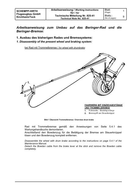
SCHEMPP-HIRTHFlugzeugbau GmbHKirchheim/Teck<strong>Arbeitsanweisung</strong> / Working Instructionsfür / forTechnische Mitteilung Nr. 825-41Technical Note No. 825-41Blatt:(Page)Blattz.:(No of pages)19<strong>Arbeitsanweisung</strong> <strong>zum</strong> <strong>Umbau</strong> <strong>auf</strong> <strong>das</strong> <strong>Beringer</strong>-<strong>Rad</strong> <strong>und</strong> <strong>die</strong><strong>Beringer</strong>-Bremse:1. Ausbau des bisherigen <strong>Rad</strong>es <strong>und</strong> Bremssystems:1. Disassembly of the present wheel and braking system:bei <strong>Rad</strong> mit Trommelbremse / for wheel with drumbrake:Bild 1 Übersicht Trommelbremse / Overview drum brake<strong>Rad</strong> mit Trommelbremse gemäß den Anweisungen von Seite 5.4.1 desWartungshandbuchs demontieren.Anschließend den Bowdenzug für <strong>die</strong> Betätigung der Bremse am Steuerknüppellösen <strong>und</strong> den Bowdenzug komplett entfernen.Disassemble the wheel with drum brake according to the instructions on page 5.4.1 of theMaintenance Manual.Detach the Bowden cable from the brake lever at the stick and remove the Bowden cablecompletely.
SCHEMPP-HIRTHFlugzeugbau GmbHKirchheim/Teck<strong>Arbeitsanweisung</strong> / Working Instructionsfür / forTechnische Mitteilung Nr. 825-41Technical Note No. 825-41Blatt:(Page)Blattz.:(No of pages)29bei <strong>Rad</strong> mit Scheibenbremse / for wheel with disc brake:Bild 2 Übersicht Scheibenbremse / Overview disc brake<strong>Rad</strong> mit Scheibenbremse gemäß den Anweisungen von Seite 5.4.2 desWartungshandbuches demontieren.Anschließend auch den Hydraulikschlauch von der Bremszange <strong>und</strong> vomBremszylinder (3) unter der Sitzwanne lösen <strong>und</strong> komplett entfernen. DenBowdenzug am Bremsgriff am Steuerknüppel (2) <strong>und</strong> am Bremszylinder (3) lösen <strong>und</strong>komplett entfernen. Bremszylinder (3) ausbauen.Bremszylinder, Bowdenzug, Hydraulikschlauch, Bremszange <strong>und</strong> <strong>Rad</strong> werden nichtmehr gebraucht.Disassemble the wheel with disc brake according to the instructions on page 5.4.2 of themaintenance manual.Detach the hydraulic hose from the brake calibre and and remove it completely. Detach theBowden cable from the brake lever at the control stick and from the brake cylinder.Disassemble the brake cylinder.Brake cylinder, Bowden cable, hydraulic hose, brake calibre and wheel aren’t requiredanymore.
SCHEMPP-HIRTHFlugzeugbau GmbHKirchheim/Teck<strong>Arbeitsanweisung</strong> / Working Instructionsfür / forTechnische Mitteilung Nr. 825-41Technical Note No. 825-41Blatt:(Page)Blattz.:(No of pages)392. Einbau des <strong>Beringer</strong>-Brems-Systems:2. Installation of <strong>Beringer</strong> braking system:bei <strong>Rad</strong> mit Trommelbremse:Mit Hilfe der beiliegenden Schablone, siehe Bild 3, werden <strong>die</strong> 4 bezeichnetenBohrungen in den Steuerspant gesetzt. In <strong>die</strong> beiden oberen Bohrungen <strong>und</strong><strong>die</strong> linke untere Bohrung werden Annietmuttern M6 gesetzt. An <strong>die</strong>senAnnietmuttern wird <strong>die</strong> Gr<strong>und</strong>platte des Bremszylinders befestigt. Die vierteBohrung <strong>die</strong>nt zur Durchführung des Bowdenzugs. Bremszylinder <strong>und</strong>Befestigungsplatte mit dem Steuerspant verschrauben.for wheel with drum brake:Set the four indicated boreholes into the stick mounting frame with the positioningdevice. Place M6-rivet nuts into the boreholes number 1, 2 and 3. The mounting plateof the brake calibre will be mounted to these rivet nuts. Borehole number 4 is the leadthrough of the Bowden cable. Attach the brake calibre and the mounting plate to thestick mounting frame.Bild 3 Schablone / Positioning devicebei <strong>Rad</strong> mit Scheibenbremse:Mit Hilfe der Schablone kontrollieren, ob <strong>die</strong> schon vorhandenen Bohrungenfür <strong>die</strong> Halterung des Bremszylinders im Bereich der Bohrungen liegen, <strong>die</strong> <strong>auf</strong>der Schablone abgebildet sind. Liegen <strong>die</strong> vorhandenen Bohrungen nurgeringfügig neben den Bohrungen der Schablone (max. 5 – 10 mm) <strong>und</strong> kann<strong>die</strong> Halteplatte des Behringer-Bremszylinders ohne Komplikationen an denvorhandenen Bohrungen befestigt werden, so können <strong>die</strong>se weiterverwendetwerden.
SCHEMPP-HIRTHFlugzeugbau GmbHKirchheim/Teck<strong>Arbeitsanweisung</strong> / Working Instructionsfür / forTechnische Mitteilung Nr. 825-41Technical Note No. 825-41Blatt:(Page)Blattz.:(No of pages)59Anschließend kann der nokon-Bowdenzug vom Bremsgriff am Steuerknüppel zurDurchführung im vorderen Steuerspant geführt <strong>und</strong> am Bremszylinder befestigtwerden. Dabei <strong>die</strong> Feder, wie <strong>auf</strong> untenstehenden Bild dargestellt, zwischenBefestigungsplatte <strong>und</strong> Befestigung des Bowdenzugs am Bremszylinder installieren:min. 0,2 – 0.5 mm Luftzwischen Betätigungshebeldes Bremszylinders <strong>und</strong>Endstück des Betätigungsseils,wenn <strong>die</strong> Bremse nichtbetätigt wird /minimum play of 0.2 to 0.5 mmbetween master cylinder handeland cable stop if system is inrelease positionBei maximalem Weg desBetätigungsseils der Bremsedarf <strong>die</strong> Feder nichtvollständig zusammengepreßt werden /Spring must not be fullycompressed at maximum travelof the braking cable.Bild 4 Bowdenzug-Befestigung / Installation of bowden cableAfter that guide the nokon Bowden cable from the brake lever at the stick to the lead throughin the stick mounting frame and attach it to the brake cylinder. Install the spring as shown inthe picture above between mounting plate and attachment of the Bowden cable to the brakecylinder.Die Bremsleitung mit dem Bremszylinder verbinden <strong>und</strong> durch <strong>die</strong> Halterungen für <strong>die</strong>Instrumentenschläuche in Richtung Fahrwerk verlegen. Bei Flugzeugen, <strong>die</strong> bishernur mit einer Trommelbremse ausgerüstet waren, muß <strong>die</strong> Durchführung derBremsleitung in den Fahrwerkskasten entsprechend gebohrt werden. Ist <strong>die</strong>Bremsleitung mit einem Entlüftungsventil versehen, so kann man <strong>die</strong>ses mit einerSchlauchschelle an einer Schraube für <strong>die</strong> Kupplungsabdeckung befestigen. DieDurchführung <strong>zum</strong> Fahrwerkskasten <strong>und</strong> auch <strong>die</strong> Befestigung des Entlüftungsventilssind <strong>auf</strong> dem Bild <strong>auf</strong> der nächsten Seite zu erkennen.Connect the brake line with the brake cylinder and guide the brake line through the supportsfor the instrument tubes in direction to the main gear. The lead through for the brake line to themain gear compartment has to be drilled suitably in sailplanes that were previously equippedwith a drum brake. If the brake line is equipped with a bleeding valve, you can attach thebleeding valve to a screw for the covering of the CG-hook with a hose clip. The lead through tothe main gear compartment and the attachment of the bleeding valve can be seen on thepicture on the next page:
SCHEMPP-HIRTHFlugzeugbau GmbHKirchheim/Teck<strong>Arbeitsanweisung</strong> / Working Instructionsfür / forTechnische Mitteilung Nr. 825-41Technical Note No. 825-41Blatt:(Page)Blattz.:(No of pages)69Durchmesser der Bohrung: 25 mmDiameter of borehole: 25 mmPosition / position:30 mm45 mmBild 5 Befestigung der Bremsleitung / Installation of brake line
SCHEMPP-HIRTHFlugzeugbau GmbHKirchheim/Teck<strong>Arbeitsanweisung</strong> / Working Instructionsfür / forTechnische Mitteilung Nr. 825-41Technical Note No. 825-41Blatt:(Page)Blattz.:(No of pages)793. Einbau des <strong>Beringer</strong>-<strong>Rad</strong>es3. Installation of the <strong>Beringer</strong> wheelIn <strong>die</strong> Felge <strong>die</strong> Bremsscheibe <strong>und</strong> auch <strong>die</strong> Bremszange einsetzen, aber <strong>die</strong> Bremsscheibenoch nicht sichern. Anschließend <strong>die</strong> Distanzhülsen entsprechend der Schnitt-Zeichnung <strong>auf</strong>der nächsten Seite (Bild 7) einsetzen <strong>und</strong> <strong>das</strong> <strong>Rad</strong> in <strong>das</strong> Fahrwerk einführen. Die <strong>Rad</strong>achsestecken, damit <strong>das</strong> <strong>Rad</strong> nicht mehr herausfällt. Anschließend <strong>die</strong> Halteplatte desBremssattels mit der Befestigungsschraube in der linken Fahrwerksstrebe fixieren <strong>und</strong> <strong>die</strong>Bremsscheibe mit dem Sicherungsdraht sichern (siehe Bild 6). Die <strong>Rad</strong>achse mit derKronenmutter festschrauben <strong>und</strong> <strong>die</strong> Kronenmutter sichern.Attach the brake disc and the brake calliper to the wheel rim but do not yet secure the brake disk.Afterwards assemble the spacers according to the drawing on the next page (“Bild 7”), insert the wheelinto gear frame and nest the wheel axle. Set the mounting plate of the brake calibre with theattachment bolt to the left gear rod and secure the brake disk with the provided safety wire (see “Bild6”). Tighten the wheel axle with the castle nut and secure the castle nut.Bild 6 Sicherung der Bremsscheibe / Securing of brake disc
SCHEMPP-HIRTHFlugzeugbau GmbHKirchheim/Teck<strong>Arbeitsanweisung</strong> / Working Instructionsfür / forTechnische Mitteilung Nr. 825-41Technical Note No. 825-41Blatt:(Page)Blattz.:(No of pages)89section A-A:Schnitt A-A:BremsscheibeNeue Distanzhülse(drehbar)Neue Distanzhülse(drehbar)<strong>Rad</strong>achseSpiel: 0,5 mmUnterlegscheibe zurFixierung des <strong>Rad</strong>lagersSpiel: 0,5 mmSpiel: 0,5 mmBefestigungsplatte fürBremssattel, fixiertdurch längere HülseBild 7 Schnittzeichnung <strong>Beringer</strong>-<strong>Rad</strong> / Sectional drawing of <strong>Beringer</strong> wheel
SCHEMPP-HIRTHFlugzeugbau GmbHKirchheim/Teck<strong>Arbeitsanweisung</strong> / Working Instructionsfür / forTechnische Mitteilung Nr. 825-41Technical Note No. 825-41Blatt:(Page)Blattz.:(No of pages)994. Entlüften des Bremssystems4. Bleeding of the brake systemDas Bremssystem ist nach den Angaben <strong>auf</strong> den Seiten 5.4.3 <strong>und</strong> 5.4.4 desWartungshandbuchs bzw. nach den Angaben in den Unterlagen der Firma <strong>Beringer</strong> zuentlüften.The brake system has to be bleeded according to the instructions on page 5.4.3 and 5.4.4 of theMaintenance manual respectively according to the instructions in the documentation of the company<strong>Beringer</strong>