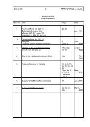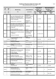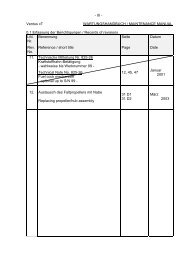
0.1 Erfassung der Berichtigungen / Record of Revisions
0.1 Erfassung der Berichtigungen / Record of Revisions
0.1 Erfassung der Berichtigungen / Record of Revisions

Create successful ePaper yourself
Turn your PDF publications into a flip-book with our unique Google optimized e-Paper software.
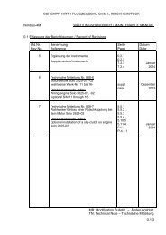
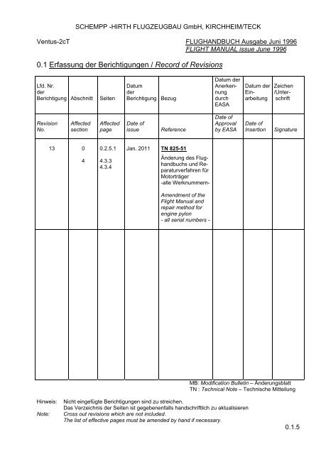
SCHEMPP -HIRTH FLUGZEUGBAU GmbH, KIRCHHEIM/TECK<br />
Ventus-2cT FLUGHANDBUCH Ausgabe Juni 1996<br />
FLIGHT MANUAL issue June 1996<br />
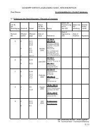
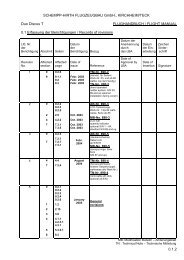
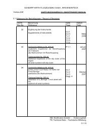
<strong>0.1</strong> <strong>Erfassung</strong> <strong>der</strong> <strong>Berichtigungen</strong> / <strong>Record</strong> <strong>of</strong> <strong>Revisions</strong><br />
Lfd. Nr.<br />
<strong>der</strong><br />
Berichtigung Abschnitt<br />
Seiten<br />
Datum<br />
<strong>der</strong><br />
Berichtigung<br />
Bezug<br />
Datum <strong>der</strong><br />
Anerkennung<br />
durch<br />
EASA<br />
Datum <strong>der</strong><br />
Einarbeitung<br />
Zeichen<br />
/Unterschrift<br />
Revision<br />
No.<br />
Affected<br />
section<br />
Affected<br />
page<br />
Date <strong>of</strong><br />
issue<br />
Reference<br />
Date <strong>of</strong><br />
Approval<br />
by EASA<br />
Date <strong>of</strong><br />
Insertion<br />
Signature<br />
13 0<br />
4<br />
0.2.5.1<br />
4.3.3<br />
4.3.4<br />
Jan. 2011 TN 825-51<br />
Än<strong>der</strong>ung des Flughandbuchs<br />
und Reparaturverfahren<br />
für<br />
Motorträger<br />
-alle Werknummern-<br />
Amendment <strong>of</strong> the<br />
Flight Manual and<br />
repair method for<br />
engine pylon<br />
- all serial numbers -<br />
MB: Modification Bulletin – Än<strong>der</strong>ungsblatt<br />
TN : Technical Note – Technische Mitteilung<br />
Hinweis:<br />
Note:<br />
Nicht eingefügte <strong>Berichtigungen</strong> sind zu streichen.<br />
Das Verzeichnis <strong>der</strong> Seiten ist gegebenenfalls handschriftlich zu aktualisieren<br />
Cross out revisions which are not included.<br />
The list <strong>of</strong> effective pages must be amended by hand if necessary.<br />
<strong>0.1</strong>.5
SCHEMPP-HIRTH FLUGZEUGBAU GmbH., KIRCHHEIM/TECK<br />
Ventus-2cT<br />
FLIGHT MANUAL<br />
(4) a) Check fuselage for damage, especially on its lower side<br />
b) Check that the STATIC pressure ports for the ASI on the<br />
tail boom (0.8 m /2.62 ft forward <strong>of</strong> the base <strong>of</strong> the fin) and<br />
below the spar stub cut-out are clear<br />
Visual inspection <strong>of</strong> the power plant<br />
CAUTION: IGNITION TO BE SWITCHED OFF !<br />
c) Check – while power plant extends – that the tip <strong>of</strong> the prop blade<br />
pointing to the front has sufficient clearance to the rim <strong>of</strong><br />
the engine compartment (blade must not get jammed below the<br />
rim)<br />
d) Check propeller for damage and ease <strong>of</strong> movements.<br />
Being in the lowermost position, each blade must unfold automatically,<br />
otherwise the bolt at the blade root should be lubricated<br />
e) Check power plant for loose bolts and nuts, check all locks and<br />
stops<br />
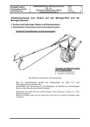
f) Check exhaust system and engine pylon for damage and cracks,<br />
especially at the welding joints. The area around the lower engine<br />
suspension must be checked thoroughly, see picture below. If<br />
necessary, the engine pylon should be cleaned with a cloth in this<br />
area. If necessary a torch should be used for the check.<br />
Check this area also<br />
from the rear side<br />
Check the vertical<br />
tube from every side<br />
Note: For better illustration the front plug connector is removed.<br />
January 2011 TN 825-51 approved<br />
Revision 13 4.3.3
SCHEMPP-HIRTH FLUGZEUGBAU GmbH., KIRCHHEIM/TECK<br />
Ventus-2cT<br />
FLIGHT MANUAL<br />
(4) a) Check fuselage for damage, especially on its lower side<br />
b) Check that the STATIC pressure ports for the ASI on the<br />
tail boom (0.8 m /2.62 ft forward <strong>of</strong> the base <strong>of</strong> the fin) and<br />
below the spar stub cut-out are clear<br />
Visual inspection <strong>of</strong> the power plant<br />
Completely extend the power plant with the manual operation switch<br />
CAUTION: IGNITION TO BE SWITCHED OFF !<br />
c) Check – while power plant extends – that the tip <strong>of</strong> the prop blade<br />
pointing to the front has sufficient clearance to the rim <strong>of</strong><br />
the engine compartment (blade must not get jammed below the<br />
rim)<br />
d) Check propeller for damage and ease <strong>of</strong> movements.<br />
Being in the lowermost position, each blade must unfold automatically,<br />
otherwise the bolt at the blade root should be lubricated<br />
e) Check power plant for loose bolts and nuts, check all locks and<br />
stops<br />
f) Check exhaust system and engine pylon for damage and cracks,<br />
especially at the welding joints. The area around the lower engine<br />
suspension must be checked thoroughly, see picture below. If<br />
necessary, the engine pylon should be cleaned with a cloth in this<br />
area. If necessary a torch should be used for the check.<br />
Check this area also<br />
from the rear side<br />
Check the vertical<br />
tube from every side<br />
Note: For better illustration the front plug connector is removed.<br />
January 2011 TN 825-51 approved<br />
Revision 13 TN 825-42 4.3.3
SCHEMPP-HIRTH FLUGZEUGBAU GmbH., KIRCHHEIM/TECK<br />
Ventus-2cT<br />
FLIGHT MANUAL<br />
(4) (continued)<br />
g) Check components, lines, hoses, pipes and wires etc. for<br />
chafing marks<br />
h) Check condition, function and tension <strong>of</strong> engine arresting cables,<br />
engine door operating cables and door actuating mechanism<br />
i) Check that the retaining springs are hooked up to the engine<br />
arresting wires<br />
j) Pull back decompression handle and hold – prop must rotate freely.<br />
Release handle and check that the actuating lever on the pylon<br />
returns to its stop.<br />
The gap between the decompression valve interconnecting link and<br />
the actuating lever on the pylon must be at least 2.0 mm (0.08 in.)<br />
(5) a) Check condition <strong>of</strong> tail skid or wheel. If the latter is installed,<br />
check tire pressure:<br />
2.0 bar / 29 psi (see placard)<br />
b) Should a total energy compensation probe be used, mount it<br />
and check the line (when blowing gently from the front to the probe<br />
with pneumatic valve for the TEK probe set at “Power <strong>of</strong>f”, the<br />
variometer(s) connected should read “climb”)<br />
c) Check that the fin-mounted PITOT tube is clear.<br />
When blowing gently into this probe, the ASI must register<br />
(with pneumatic valve for the pitot pressure set at “Power <strong>of</strong>f”)<br />
d) Check that the opening for the fuel tank vent line<br />
(at the upper end <strong>of</strong> the fin) is clear<br />
Should a water ballast fin tank be installed (option):<br />
e) Check that the fin tank spill holes are clear<br />
f) Check water ballast level in fin tank (in case <strong>of</strong> doubt,<br />
discharge ballast)<br />
g) Check that the dump hole for the fin tank in the tail wheel<br />
fairing (if installed) is clear<br />
January 2011 TN 825-51 approved<br />
Revision 13 4.3.4