canopy - Schempp-Hirth Flugzeugbau GmbH
canopy - Schempp-Hirth Flugzeugbau GmbH
canopy - Schempp-Hirth Flugzeugbau GmbH

You also want an ePaper? Increase the reach of your titles
YUMPU automatically turns print PDFs into web optimized ePapers that Google loves.
SCHEMPP-HIRTH FLUGZEUGBAU <strong>GmbH</strong>., KIRCHHEIM/TECK<br />
Duo Discus<br />
WARTUNGSHANDBUCH / MAINTENANCE MANUAL<br />
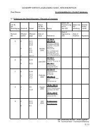
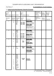
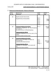
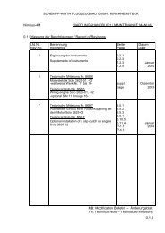
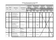
0.1 Erfassung der Berichtigungen / Record of Revisions<br />
Lfd.Nr.<br />
Rev.No.<br />
Benennung<br />
Reference<br />
Seite<br />
Page<br />
Datum<br />
Date<br />
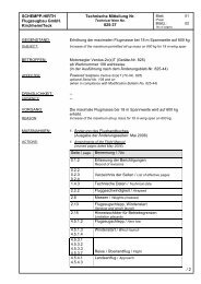
20 Technische Mitteilung Nr. 396-16<br />
Optionale Verwendung der Segelflugzeug-<br />
Rümpfe nach dem<br />
ÄB-Nr. 396-15 (Duo x) oder<br />
ÄB-Nr. 396-16 (Duo xL)<br />
Werk-Nr. 1 bis 533 und 535 bis 541<br />
Technical Note No. 396-16<br />
Optional use of fuselages according to<br />
MB-No. 396-15 (Duo x) or<br />
MB-No. 396-16 (Duo xL)<br />
SN 1 through 533 and 535 through 541<br />
0.2.1<br />
0.2.2<br />
0.2.3<br />
1.1<br />
1.2.3<br />
2.1.2<br />
3.1.2<br />
3.2.2<br />
5.4.1.1<br />
5.4.1.2<br />
6.2.2<br />
6.4.2<br />
6.4.3<br />
6.6.1<br />
6.6.2<br />
6.7<br />
7.1*)<br />
7.2.1*)<br />
7.2.2*)<br />
7.2.3*)<br />
7.2.4*)<br />
7.2.5*)<br />
8.2<br />
8.3*)<br />
8.5<br />
Diagramm 3*)<br />
Diagramm 4<br />
Rep.1<br />
Rep. 2<br />
Rep. 3<br />
Rep. 4<br />
*) nur bei Verwendung<br />
des „xL“-<br />
Rumpfes nach dem<br />
(ÄB-Nr. 396-16)<br />
only use for „xL“<br />
fuselage<br />
(MB-No. 396-16)<br />
Februar<br />
2008<br />
MB: Modification Bulletin – Änderungsblatt<br />
TN: Technical Note – Technische Mitteilung<br />
0.1.5
SCHEMPP-HIRTH FLUGZEUGBAU <strong>GmbH</strong>., KIRCHHEIM/TECK<br />
Duo Discus<br />
MAINTENANCE MANUAL<br />
1. Description of components and systems<br />
Further descriptions and assembly are provided on sections 1.4, 1.5, 4.2 and<br />
7 of the Flight Manual.<br />
1.1 Airframe<br />
The “Duo Discus ” is a two-seat sailplane for advanced training and crosscountry<br />
flying, constructed from fiber reinforced plastic (FRP), featuring a<br />
T-tail (with fixed horizontal stabilizer and elevator).<br />
Wing<br />
The wing shells are a glass and carbon fiber/foam-sandwich with spar<br />
flanges made from carbon fiber rovings and shear webs constructed as a<br />
glass fiber/foam-sandwich.<br />
Fuselage<br />
This is a pure carbon fiber (CFRP) lay-up with a aramid fiber reinforcement in<br />
the cockpit area for high energy absorbtion.<br />
Horizontal tailplane<br />
The horizontal tailplane consists of a fixed stabilizer with elevator.<br />
The stabilizer is a GFRP/CFRP/foam-sandwich, the elevator halves are a<br />
pure carbon fiber lay-up.<br />
Vertical tail<br />
Both fin and rudder are constructed as a glass fiber/foam-sandwich.<br />
February 2008 MB-No. 396-15 resp. MB-No. 396-16<br />
Revision 20 TN-No. 396-15 (x / xL) 1.1
SCHEMPP-HIRTH FLUGZEUGBAU <strong>GmbH</strong>., KIRCHHEIM/TECK<br />
Duo Discus<br />
MAINTENANCE MANUAL<br />
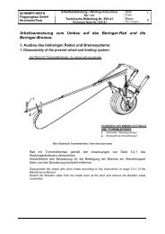
Undercarriage with wheel brake<br />
Steel push-pull tubes connect the u/c operating handles in the cockpit (which<br />
are guided in a gate) to the actuating arm on the rear pivot shaft of the u/c<br />
assembly. A gas strut on the u/c assists in retracting the wheel.<br />
For “wheel up”, the travel of the u/c operating tube in the cockpit is restricted<br />
by the actuating arm resting against the steel tube center frame; for “wheel<br />
down”, the extension stop is the overcentering of the rear u/c struts.<br />
Additionally the travel of the u/c operating tube in the cockpit is restricted by<br />
the gate guiding the front operating handle.<br />
The hydraulic main wheel disc brake is actuated by steel cables (running in a<br />
bowden conduit), connecting the stick mounted brake handles to the wheel<br />
brake master cylinder.<br />
A view of the undercarriage is provided in diagram 4.<br />
Water ballast system(s)<br />
For a description of the water ballast system(s) refer to section 7.9 of the<br />
Flight Manual.<br />
February 2008 MB-No. 396-15 resp. MB-No. 396-16<br />
Revision 20 TN-No. 396-15 (x / xL) 1.2.3
SCHEMPP-HIRTH FLUGZEUGBAU <strong>GmbH</strong>., KIRCHHEIM/TECK<br />
Duo Discus MAINTENANCE MANUAL<br />
170 mm<br />
[6.69 in.]<br />
TAILPLANE INCIDENCE:<br />
-2.65°<br />
WING INCIDENCE:<br />
1.5°<br />
410 mm [16.14 in.]<br />
176 mm<br />
[6.93 in.]<br />
AILERONS:<br />
Up:<br />
71 ± 5 mm<br />
[2.80 ± 0.20 in.]<br />
Down:<br />
36 ± 5 mm<br />
[1.42 ± 0.20 in.]<br />
WING SWEEPBACK:<br />
Negative sweepback of leading edge<br />
on trapezoidal inboard wing section<br />
228 ± 20 mm<br />
[8.98 ± 0.79 in.]<br />
RIGGING DATA AND<br />
CONTROL SURFACE DEFLECTIONS<br />
February 2008 MB 396-15<br />
Revision 20 TN 396-16 (x) 2.1.2
SCHEMPP-HIRTH FLUGZEUGBAU <strong>GmbH</strong>., KIRCHHEIM/TECK<br />
Duo Discus MAINTENANCE MANUAL<br />
170 mm<br />
[6.69 in.]<br />
TAILPLANE INCIDENCE:<br />
-2.65°<br />
WING INCIDENCE:<br />
1.5°<br />
410 mm [16.14 in.]<br />
176 mm<br />
[6.93 in.]<br />
AILERONS:<br />
Up:<br />
71 ± 5 mm<br />
[2.80 ± 0.20 in.]<br />
Down:<br />
36 ± 5 mm<br />
[1.42 ± 0.20 in.]<br />
WING SWEEPBACK:<br />
Negative sweepback of leading edge<br />
on trapezoidal inboard wing section<br />
228 ± 20 mm<br />
[8.98 ± 0.79 in.]<br />
RIGGING DATA AND<br />
CONTROL SURFACE DEFLECTIONS<br />
February 2008 TN 396-12 / MB 396-15<br />
Revision 20 TN 396-16 (x) 2.1.2
SCHEMPP-HIRTH FLUGZEUGBAU <strong>GmbH</strong>., KIRCHHEIM/TECK<br />
Duo Discus<br />
MAINTENANCE MANUAL<br />
• Tow release mechanism(s)<br />
Checks should be carried out in accordance with the<br />
“Operating & Maintenance Instructions for the TOST tow Release Mechanism(s)”<br />
- see also section 9 “Service Instructions”.<br />
• Instruments<br />
In the case of all installed instruments and equipment, the instructions of<br />
the relevant manufacturer should be followed.<br />
• Safety harness<br />
At present the service time of the webbing on the restraint systems<br />
available is limited to twelve (12) years including the time of storage.<br />
See also the service instructions provided by the relevant manufacturer.<br />
• Gas strut<br />
A tension gas strut is attached to the U/C.<br />
The rod of the gas strut must always be perfectly clean and must not be<br />
damaged in any way whatsoever.<br />
If oil has escaped through the seal, the gas strut must be replaced.<br />
February 2008<br />
Revision 20 TN-No. 396-16 (x / xL) 3.1.2
SCHEMPP-HIRTH FLUGZEUGBAU <strong>GmbH</strong>., KIRCHHEIM/TECK<br />
Duo Discus<br />
MAINTENANCE MANUAL<br />
After cleaning the entire aircraft, the following checks should be made:<br />
• Check the aircraft externally for damage such as cracks, holes, scratches,<br />
buckling and delamination.<br />
If the outer layer(s) of a component, constructed as a sandwich, has been<br />
damaged, then the inner skin must be checked as well.<br />
It is recommended to call upon expert assistance.<br />
• All fittings which are mounted on GFRP (CFRP) structures must be<br />
checked to confirm there has been no movement.<br />
Check also the CFRP (GFRP) structure at the fittings for cracks, white<br />
spots and delamination.<br />
• Check all accessible metal parts for damage.<br />
It is generally found, however, that if the aircraft is operated correctly, no<br />
damage will have occured.<br />
If repairs are necessary, then the manufacturer’s recommendations<br />
should be followed.<br />
• Check all accessible metal parts such as fittings, control rods (push/pull<br />
tubes) and actuating levers for corrosion.<br />
If necessary, remove the rust, clean thoroughly and apply a fresh corrosion<br />
protection.<br />
The special primer and paint for this surface protection may be obtained<br />
from <strong>Schempp</strong>-<strong>Hirth</strong> <strong>Flugzeugbau</strong> <strong>GmbH</strong>.<br />
• Linkage for attaching and locking the <strong>canopy</strong><br />
Check linkage attaching/detaching and locking/opening the <strong>canopy</strong> for<br />
any damage.<br />
Check guides for locking rod on <strong>canopy</strong> frame, locating pins on fuselage<br />
and front GFRP hinge for delamination/cracks. Check rear metal hinge for<br />
deformation.<br />
February 2008<br />
Revision 20 TN-No. 396-16 (x / xL) 3.2.2
SCHEMPP-HIRTH FLUGZEUGBAU <strong>GmbH</strong>., KIRCHHEIM/TECK<br />
Duo Discus<br />
MAINTENANCE MANUAL<br />
5.4 Main wheel with hydraulic disc brake<br />
Main wheel TOST:<br />
When removing the main wheel to clean and grease it, first remove the two<br />
bolts attaching the brake back plate to the brake cylinder, then remove brake<br />
calliper (hydraulic pressure hose remains attached).<br />
Disassemble the attachment bolt of the brake shield on the inner side of the<br />
swinging arm.<br />
Next remove cotter pin and castle nut from one side of the wheel axle and<br />
withdraw the latter. Take out spacer on the ride side of the wheel and remove<br />
the wheel (take care that no washers, spacers or bushings get lost).<br />
Prior to re-assembly, clean all parts and lubricate bearings, bushings and the<br />
axle.<br />
Observe the instructions provided by the supplier of the wheel,<br />
TOST company, Munich, Germany<br />
Main wheel BERINGER<br />
Observe the instructions provided by the supplier of the wheel,<br />
BERINGER company, Chǎtelneuf, France.<br />
NOTE: Do not disconnect the hydraulic pressure hose from the brake<br />
cylinder and do not actuate the wheel brake while brake calliper is<br />
removed from the brake disc.<br />
The hydraulic wheel brake may be actuated by the handle provided at the<br />
control sticks.<br />
Front wheel-brake:<br />
The Bowden cable is directly connected with the actuating segment of the<br />
brake master cylinder.<br />
Rear wheel-brake:<br />
The Bowden cable is connected to the attachment of the brake master<br />
cylinder. The tube of the Bowden cable fits to the actuating segment of the<br />
brake master cylinder and actuates the actuating segment when the rear<br />
wheel brake is applied.<br />
Whenever a reduced effectiveness of the wheel brake is observed,<br />
see page 5.4.1.2.<br />
February 2008 MB-No. 396-15 resp. MB-No. 396-16<br />
Revision 20 TN-No. 396-16 (x / xL) 5.4.1.1
SCHEMPP-HIRTH FLUGZEUGBAU <strong>GmbH</strong>., KIRCHHEIM/TECK<br />
Duo Discus<br />
MAINTENANCE MANUAL<br />
In case of reduced effectiveness of the wheel brake<br />
1. Check brake pads:<br />
If the thickness of the brake pads is less then 1.5 to 2mm replace brake pads.<br />
Therefore both parts of the brake calliper have to be removed.<br />
2. Check leak tightness of the hydraulic-system.<br />
3. Check brake fluid:<br />
a) Remove front seat pan<br />
b) Remove cover of brake fluid-container<br />
c) If necessary refill missing brake fluid and bleed the braking system as<br />
described on page 5.4.2<br />
d) Check effectiveness of the wheel brake. Afterwards reassemble the<br />
disassembled parts<br />
4. Readjustment of the Bowden cables:<br />
Note:<br />
a) The Bowden cables may be readjusted at the adjustment<br />
point at the control stick until the gap between the<br />
actuating segment on the brake master cylinder and the<br />
cylinder case is about 1.0 mm (0.04 in). To do this the<br />
wheel brake has to be relieved.<br />
To check the readjustment pull the brake handle several<br />
times. With relieved wheel brake:<br />
i) the wheel can still be rotated by hand<br />
ii)<br />
it has still to be possible to push the brake<br />
calliper back in direction to the wheel by hand<br />
b) Check the function of the wheel brake after assembling<br />
the seat pan<br />
Normally the brake system has to be bleeded, if the fuselage is stored inverted!<br />
If the brake handle is fixed in pulled position during the inverted storage of the<br />
fuselage, the bleeding of the brake system usually is not necessary<br />
February 2008 MB-No. 396-15 resp. MB-No. 396-16<br />
Revision 20 TN-No. 396-16 (x / xL) 5.4.1.2
SCHEMPP-HIRTH FLUGZEUGBAU <strong>GmbH</strong>., KIRCHHEIM/TECK<br />
Duo Discus<br />
MAINTENANCE MANUAL<br />
Datum plane:<br />
Aircraft attitude:<br />
Wing leading edge at root rib<br />
Tail jacked up such that a wedge-shaped<br />
block, 100 : 4.5, placed on the rear top<br />
fuselage, is horizontal along its upper<br />
edge.<br />
Distance main wheel: a = 8 mm (0.31 in.)<br />
Distance tail wheel:<br />
Distance skid:<br />
b = 5322 mm (209.53 in.)<br />
b = 5357 mm (210.91 in.)<br />
Empty mass c/g position:<br />
x =<br />
W 2<br />
x b<br />
W<br />
+ a<br />
C/G position in flight:<br />
(just given for the case that the “c/g position in flight” is to be determined by<br />
weighing rather than by computing it on the basis of the empty mass c/g position)<br />
The aircraft is to be weighed fully equipped (crew with parachutes and<br />
complete outfit incl. barograph, cushions, cameras etc.) Seat back and rudder<br />
pedals should be correctly adjusted for this purpose.<br />
x =<br />
W 2 loaded<br />
x b<br />
W empty<br />
+ W disposable<br />
+ a<br />
February 2008 MB-No. 396-15 resp. MB-No. 396-16<br />
Revision 20 TN-No. 396-16 (x / xL) 6.2.2
SCHEMPP-HIRTH FLUGZEUGBAU <strong>GmbH</strong>., KIRCHHEIM/TECK<br />
Duo Discus<br />
MAINTENANCE MANUAL<br />
Forward c/g limits: With a maximum seat load of 110 kg (242.5 lb)<br />
on either seat and with maximum permitted water<br />
ballast<br />
Rearward c/g limits: With various minimum loads on the front seat<br />
(allowance for 5.0 kg / 11.02 lb baggage already<br />
made)<br />
To facilitate the checking of the empty mass center of gravity, the table<br />
below shows – at different empty mass values – the maximum permissible<br />
load on the tail wheel, with various loads on the front seat and in<br />
relation to the most rearward c/g position.<br />
The actual load on the tail wheel is determined with the aircraft in<br />
weighing attitude, i.e. main wheel on the ground and tail jacked up as<br />
described on page 6.2.1.<br />
If the load on the tail wheel does not exceed the corresponding value in<br />
the table, the center of gravity is within the permitted range.<br />
Empty mass<br />
Load on tail wheel (or skid) with a minimum seat load of:<br />
70 154 75 165 80 176 85 187 90 198<br />
kg lb kg lb kg lb kg lb kg lb kg lb<br />
410 904 39.7 87.5 41.2 90.8 42.8 94.4 44.3 97.7 45.9 101.2<br />
420 926 40.1 88.4 41.7 91.9 43.2 95.3 44.8 98.8 46.3 102.1<br />
430 948 40.6 89.5 42.1 92.8 43.7 96.4 45.2 99.7 46.8 103.2<br />
440 970 41.1 90.6 42.6 93.9 44.2 97.5 45.7 100.8 47.3 104.3<br />
450 992 41.5 91.5 43.1 95.0 44.6 98.3 46.2 101.9 47.7 105.2<br />
460 1014 42.0 92.6 43.5 95.9 45.1 99.4 46.6 102.8 48.2 106.3<br />
470 1036 42.4 93.5 44.0 97.0 45.5 100.3 47.1 103.9 48.6 107.2<br />
480 1058 42.9 94.6 44.4 97.9 46.0 101.4 47.5 104.7 49.1 108.3<br />
490 1080 43.3 95.5 44.9 99.0 46.4 102.3 48.0 105.8 49.5 109.1<br />
500 1103 43.8 96.6 45.3 99.9 46.9 103.4 48.4 106.7 50.0 110.3<br />
Note:<br />
Should a tail skid be fitted (instead of a tail wheel), the above values are<br />
to be multiplied by a factor of 0.993).<br />
February 2008 MB-No. 396-15<br />
Revision 20 TN-No. 396-16 (x) 6.4.2
SCHEMPP-HIRTH FLUGZEUGBAU <strong>GmbH</strong>., KIRCHHEIM/TECK<br />
Duo Discus<br />
MAINTENANCE MANUAL<br />
Empty mass c/g range<br />
in. mm<br />
23.62 600<br />
23.23 590<br />
22.83 580<br />
22.44 570<br />
22.05 560<br />
21.65 550<br />
21.26 540<br />
20.87 530<br />
20.47 520<br />
90kg<br />
198lb<br />
85kg<br />
187lb<br />
20.08 510<br />
19.69 500<br />
19.29 490<br />
18.90 480<br />
18.50 470<br />
80kg<br />
176lb<br />
75kg<br />
165lb<br />
70kg<br />
154lb<br />
18.11 460<br />
17.72 450<br />
17.32 440<br />
FOREMOST EMPTY<br />
MASS C/G POS.<br />
16.93 430<br />
EMPTY MASS (kg / lb)<br />
500<br />
1103<br />
kg<br />
lb<br />
February 2008 MB-No. 396-15<br />
Revision 20 TN-No. 396-16 (x) 6.4.3
SCHEMPP-HIRTH FLUGZEUGBAU <strong>GmbH</strong>., KIRCHHEIM/TECK<br />
Duo Discus<br />
MAINTENANCE MANUAL<br />
6.6 Useful load<br />
Load on the seats<br />
a) Water ballast fin tank not installed<br />
Note:<br />
(*) Depending on its equipment and the installation of fixed trim ballast, the actual<br />
minimum and/or maximum seat loads of this “Duo Discus” (to which this manual<br />
refers) may differ from the above typical weights.<br />
The placards in the cockpit must always show the actual weights, which are also<br />
to be entered in the log chart – see flight manual, page 6.2.3.<br />
Neither the maximum permitted all-up mass nor the maximum mass of the non-lifting<br />
parts must be exceeded.<br />
Determination of the maximum permitted load on the seats:<br />
Flown solo:<br />
Two occupants:<br />
SEAT<br />
LOAD<br />
front<br />
seat load<br />
rear<br />
seat load<br />
LOAD ON THE SEATS<br />
(crew incl. parachutes)<br />
TWO PERSONS<br />
min. max.<br />
70* kg<br />
154* lb<br />
at choice<br />
Maximum cockpit seatload<br />
110* kg<br />
243* lb<br />
110* kg<br />
243* lb<br />
Always 110 kg (242.5 lb)<br />
ONE PERSON<br />
min. max.<br />
70* kg<br />
154* lb<br />
110* kg<br />
243* lb<br />
Maximum cockpit load (load on both seats) may not be<br />
exceeded. For seat loads below the placarded minimum<br />
refer to Flight manual - section 6.2<br />
The total of the loads on front and rear seat has to be lower<br />
than the maximum cockpit seatload.<br />
At the same time pay attention, that the load on each seat<br />
stays below 110 kg (242.5 lb)<br />
Maximum seat load: This is the difference between the maximum permitted mass of<br />
the non-lifting parts (440 kg / 970 lb) and their actual mass<br />
(refer to last weighing report).<br />
b) Water ballast fin tank installed<br />
Note:<br />
SEAT<br />
LOAD<br />
front<br />
seat load<br />
rear<br />
seat load<br />
LOAD ON THE SEATS<br />
(crew incl. parachutes)<br />
TWO PERSONS<br />
min. max.<br />
100 **<br />
220 kg 100 **<br />
*<br />
** lb 110*<br />
243* kg 220 *<br />
kg<br />
** lb<br />
( 70* kg)<br />
lb ( 70* kg)<br />
(154* lb)<br />
(154* lb)<br />
110*<br />
at choice<br />
243* kg<br />
lb<br />
Maximum cockpit seatload<br />
ONE PERSON<br />
min. max.<br />
110*<br />
243* kg<br />
lb<br />
Maximum cockpit load (load on both seats) may not be<br />
exceeded. For seat loads below the placarded minimum refer<br />
to Flight manual - section 6.2. The value shown in parenthesis<br />
may be used after having thoroughly checked the ballast<br />
quantity in the fin tank and the appropriate loading chart.<br />
(*) Depending on its equipment and the installation of fixed trim ballast, the actual<br />
minimum and/or maximum seat loads of this “Duo Discus” (to which this manual<br />
refers) may differ from the above typical weights.<br />
If so, the log charts and the placards must be altered accordingly.<br />
(**) 1. For safety reasons the minimum seat load for flights with empty fin tank must<br />
be increased by 30 kg (66 lb) so as to allow for an unnoticed filled fin tank.<br />
2. Adding the mass of 30 kg (66 lb) is not required, however, if the pilot either<br />
- dumps all water ballast (prior to take off)<br />
or<br />
- determines the ballast quantity in the fin tank and ensures that it is<br />
compensated by an appropriate load in the wing tanks and/or on the<br />
aft seat.<br />
The placards in the cockpit must always show the actual weights (including those<br />
allowing for a filled fin tank **), which are also to be entered in the log chart – see<br />
flight manual, page 6.2.3.<br />
Neither the maximum permitted all-up mass nor the maximum mass of the non-lifting<br />
parts must be exceeded.<br />
February 2008 MB-No. 396-15 / TN-No. 396-13<br />
Revision 20 TN-No. 396-16 (x)<br />
6.6.1
Duo Discus<br />
SCHEMPP-HIRTH FLUGZEUGBAU <strong>GmbH</strong>., KIRCHHEIM/TECK<br />
MAINTENANCE MANUAL<br />
For establishing a "Weight & Balance Report" the following lever arms<br />
are to be used:<br />
Trim ballast under front instrument<br />
panel<br />
Trim ballast on right hand side of<br />
front control stick mounting frame<br />
Pilot, front seat (with parachute or<br />
back cushion)<br />
Pilot, rear seat (with parachute or<br />
back cushion)<br />
Battery at rear control stick<br />
mounting frame<br />
Center of gravity of:<br />
2055 mm forward of datum<br />
80.91 in.<br />
1855 mm forward of datum<br />
73.03 in.<br />
1400 mm forward of datum<br />
55.12 in.<br />
290 mm forward of datum<br />
11.42 in.<br />
680 mm forward of datum<br />
26.77 in.<br />
Main wheel 8 mm aft of datum<br />
0.31 in<br />
Waterballast, wings 65 mm aft of datum<br />
2.56 in.<br />
Tail wheel 5330 mm aft of datum<br />
209.84 in.<br />
Tail skid 5365 mm aft of datum<br />
211.22 in.<br />
Water ballast, fin 5320 mm aft of datum<br />
209.45 in.<br />
Baggage 1000 mm aft of datum<br />
39.37 in.<br />
February 2008 MB-No. 396-15<br />
Revision 20 TN-No. 396-16<br />
6.6.2
SCHEMPP-HIRTH FLUGZEUGBAU <strong>GmbH</strong>., KIRCHHEIM/TECK<br />
Duo Discus<br />
MAINTENANCE MANUAL<br />
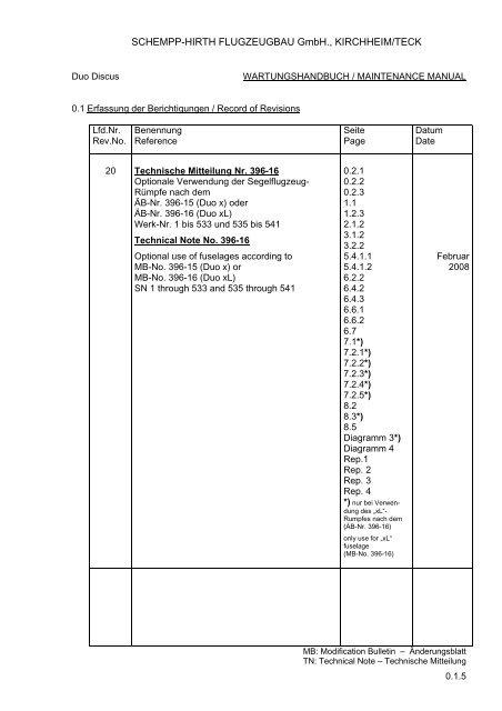
6.7 Mass – C/G diagram<br />
lb<br />
kg<br />
1543 700<br />
MAXIMUM ALL-UP MASS<br />
1433 650<br />
ALL - UP MASS (kg / lb)<br />
1378 625<br />
1323 600<br />
1257 570<br />
1213 550<br />
1135 515<br />
FORE MOST C/G POSITION<br />
PERMITTED<br />
RANGE<br />
REARMOST C/G POSITION<br />
1102 500<br />
1038 471<br />
mm<br />
in.<br />
X (mm / in.) aft of datum<br />
in flight<br />
February 2008 MB 396-15<br />
Revision 20 TN 396-16 (x) 6.7
SCHEMPP-HIRTH FLUGZEUGBAU <strong>GmbH</strong>., KIRCHHEIM/TECK<br />
Duo Discus<br />
MAINTENANCE MANUAL<br />
without fin tank<br />
LOAD ON THE SEATS<br />
(crew incl. parachutes)<br />
SEAT LOAD TWO PERSONS ONE PERSON<br />
min. max. min. max.<br />
front<br />
seat load<br />
rear<br />
seat load<br />
70* kg<br />
154* lb<br />
at<br />
choice<br />
110* kg<br />
243* lb<br />
110* kg<br />
243* lb<br />
70* kg<br />
154* lb<br />
110* kg<br />
243* lb<br />
Maximum cockpit seat load 220* kg / 485* lb<br />
Maximum cockpit load (load on both seats) may not<br />
be exceeded. For seat loads below the placarded<br />
minimum refer to Flight manual - section 6.2.<br />
(if installed)<br />
fin tank installed<br />
LOAD ON THE SEATS<br />
(crew incl. parachutes)<br />
SEAT LOAD TWO PERSONS ONE PERSON<br />
min. max. min. max.<br />
100* kg<br />
100* kg<br />
front 220* lb 110* kg 220* lb 110* kg<br />
seat load ( 70* kg) 243* lb ( 70* kg) 243* lb<br />
(154* lb)<br />
(154* lb)<br />
rear<br />
seat load<br />
at<br />
choice<br />
110* kg<br />
243* lb<br />
Maximum cockpit seat load 220* kg / 485* lb<br />
Maximum cockpit load (load on both seats) may not<br />
be exceeded. For seat loads below the placarded<br />
minimum refer to Flight manual - section 6.2.<br />
The value shown in parenthesis may be used after<br />
having thoroughly checked the ballast quantity in the<br />
fin tank and the appropriate loading chart.<br />
Placing:<br />
Cockpit inner skin on<br />
the right for either seat<br />
WHEN FLOWN SOLO, THE PLACARDED<br />
MINIMUM FRONT SEAT LOAD MAY BE<br />
REDUCED BY UP TO:<br />
NUMBER OF LEAD<br />
PLATES REQUIRED<br />
- 05 kg (11 lb) 1<br />
- 10 kg (22 lb) 2<br />
- 15 kg (33 lb) 3<br />
Cockpit inner skin on the right<br />
(front seat only)<br />
- 20 kg (44 lb) 4<br />
- 25 kg (55 lb) 5<br />
- 30 kg (66 lb) 6<br />
LOCKING PIN FLUSH<br />
WITH UPPER SURFACE<br />
Locking device for outbd. wing panels<br />
Outbd. end of main wing panels<br />
February 2008 MB-No. 396-15 / TN-No. 396-13<br />
Revision 20 TN-No. 396-16 (x) 8.2
SCHEMPP-HIRTH FLUGZEUGBAU <strong>GmbH</strong>., KIRCHHEIM/TECK<br />
Duo Discus MAINTENANCE MANUAL<br />
Placing:<br />
Locking of <strong>canopy</strong><br />
On red locking lever on the left,<br />
provided for either seat<br />
(if installed)<br />
Ballast in fin tank is dumped<br />
simultaneously with wing tanks<br />
Operating knob for dumping<br />
ballast from wing tanks<br />
Front seat above guide slot for operating<br />
knob on cockpit inner skin on the right<br />
Air quantity<br />
Next to operating knob protruding<br />
from front instrument panel<br />
push<br />
pull<br />
Airstream direction<br />
Next to operating knob protruding<br />
from front instrument panel<br />
C A N O P Y<br />
attachment / detachment<br />
Canopy<br />
attachment/detachment<br />
Above operating handle on<br />
cockpit inner skin on the right<br />
for either seat<br />
February 2008 MB 396-15<br />
Revision 20 TN 396-16 (x) 8.5
SCHEMPP-HIRTH FLUGZEUGBAU <strong>GmbH</strong>., KIRCHHEIM/TECK<br />
Duo Discus T MAINTENANCE MANUAL<br />
UNDERCARRIAGE WITH RETRACTING LINKAGE<br />
AND HYDRAULIC DISC BRAKE<br />
1. Front retracting linkage<br />
2. Rear retracting linkage<br />
3. Brake handle on front control stick<br />
4. Brake handle on rear control stick<br />
5. Brake master cylinder with reservoir<br />
February 2008 MB 396-15<br />
Revision 20 TN 396-16 (x) DIAGRAM 4
SCHEMPP-HIRTH FLUGZEUGBAU <strong>GmbH</strong>., KIRCHHEIM/TECK<br />
Duo Discus<br />
REPAIR INSTRUCTIONS<br />
REPAIR INSTRUCTIONS FOR „Duo Discus “<br />
The components of this aircraft are constructed as follows:<br />
1. Inboard wing panels<br />
GFRP/foam-sandwich, with HEREX C 70.55,<br />
thickness 8 mm (0.31 in.)<br />
Wing tip extension<br />
GFRP/foam-sandwich,<br />
with HEREX C 70.55,<br />
thickness 6 mm (0.24 in.)<br />
2. Ailerons<br />
Inboard: GFRP/foam-sandwich, with HEREX C 70.55,<br />
thickness 4 mm (0.16 in.)<br />
Outboard:<br />
Pure GFRP/CFRP-shell<br />
3. Fuselage<br />
Forward section: Pure CFRP/Kevlar/GFRP-shell<br />
Aft section:<br />
Pure CFRP-shell<br />
4. Fin<br />
GFRP/foam-sandwich, with HEREX C 70.55,<br />
thickness 6 mm (0.24 in.)<br />
5. Rudder<br />
GFRP/foam-sandwich, with HEREX C 70.55,<br />
thickness 4 mm (0.16 in.)<br />
6. Horizontal stabilizer<br />
GFRP/foam-sandwich, with HEREX C 70.55,<br />
thickness 6 mm (0.24 in.)<br />
7. Elevator halves<br />
Pure CFRP-shell<br />
February 2008<br />
Revision 20 TN-No. 396-16 (x + xL) - 1 -
SCHEMPP-HIRTH FLUGZEUGBAU <strong>GmbH</strong>., KIRCHHEIM/TECK<br />
Duo Discus<br />
REPAIR INSTRUCTIONS<br />
REPAIR INSTRUCTIONS FOR „Duo Discus “<br />
The components of this aircraft are constructed as follows:<br />
1. Inboard wing panels<br />
GFRP/foam-sandwich, with HEREX C 70.55,<br />
thickness 8 mm (0.31 in.)<br />
Wing tip extension<br />
GFRP/foam-sandwich,<br />
with HEREX C 70.55,<br />
thickness 6 mm (0.24 in.)<br />
with winglets<br />
Pure GFRP/CFRP-shell<br />
2. Ailerons<br />
Inboard: GFRP/foam-sandwich, with HEREX C 70.55,<br />
thickness 4 mm (0.16 in.)<br />
Outboard:<br />
Pure GFRP/CFRP-shell<br />
3. Fuselage<br />
Forward section: Pure CFRP/Kevlar/GFRP-shell<br />
Aft section:<br />
Pure CFRP-shell<br />
4. Fin<br />
GFRP/foam-sandwich, with HEREX C 70.55,<br />
thickness 6 mm (0.24 in.)<br />
5. Rudder<br />
GFRP/foam-sandwich, with HEREX C 70.55,<br />
thickness 4 mm (0.16 in.)<br />
6. Horizontal stabilizer<br />
GFRP/foam-sandwich, with HEREX C 70.55,<br />
thickness 6 mm (0.24 in.)<br />
7. Elevator halves<br />
Pure CFRP-shell<br />
February 2008 TN-No. 396-12<br />
Revision 20 TN-No. 396-16 (x + xL) - 1 -
SCHEMPP-HIRTH FLUGZEUGBAU <strong>GmbH</strong>., KIRCHHEIM/TECK<br />
Duo Discus<br />
REPAIR INSTRUCTIONS<br />
REPAIR INSTRUCTIONS FOR „Duo Discus “<br />
The components of this aircraft are constructed as follows:<br />
1. Inboard wing panels<br />
GFRP/foam-sandwich, with HEREX C 70.55,<br />
thickness 8 mm (0.31 in.)<br />
Wing tip extension<br />
GFRP/foam-sandwich,<br />
with HEREX C 70.55,<br />
thickness 6 mm (0.24 in.)<br />
with winglets<br />
Pure GFRP/CFRP-shell<br />
2.a Ailerons<br />
Inboard: GFRP/foam-sandwich, with HEREX C 70.55,<br />
thickness 4 mm (0.16 in.)<br />
Outboard:<br />
Pure GFRP/CFRP-shell<br />
2.b Trailing edge flap<br />
GFRP/foam-sandwich,<br />
with HEREX C 70.55,<br />
thickness 4 mm (0.16 in.)<br />
3. Fuselage<br />
Forward section: Pure CFRP/Kevlar/GFRP-shell<br />
Aft section:<br />
Pure CFRP-shell<br />
4. Fin<br />
GFRP/foam-sandwich, with HEREX C 70.55,<br />
thickness 6 mm (0.24 in.)<br />
5. Rudder<br />
GFRP/foam-sandwich, with HEREX C 70.55,<br />
thickness 4 mm (0.16 in.)<br />
6. Horizontal stabilizer<br />
GFRP/foam-sandwich, with HEREX C 70.55,<br />
thickness 6 mm (0.24 in.)<br />
7. Elevator halves<br />
Pure CFRP-shell<br />
February 2008 MB-No. 396-15 resp. MB-No. 396-16<br />
Revision 20 TN-No. 396-16 (x / xL) - 1 -
SCHEMPP-HIRTH FLUGZEUGBAU <strong>GmbH</strong>., KIRCHHEIM/TECK<br />
Duo Discus<br />
REPAIR INSTRUCTIONS<br />
The first stage in carrying out repairs on components constructed from fiber reinforced<br />
plastic (FRP) is to examine the construction of the component at the location<br />
in question and to proceed in accordance with the latest applicable issue of<br />
the<br />
„REPAIR INSTRUCTIONS FOR SCHEMPP-HIRTH SAILPLANES<br />
AND POWERED SAILPLANES CONSTRUCTED FROM FIBER<br />
REINFORCED PLASTIC“<br />
General considerations<br />
For repairs only the following resin systems must be used:<br />
1. For GFRP-components<br />
Resin Hardener Mixing proportion<br />
by weight<br />
L 285 286 or 287 100 : 38<br />
LY 5052 HY 5052 100 : 38<br />
L 335 335 or 340 100 : 38<br />
Curing : 15 hours at 50° C (122° F)<br />
2. For CFRP/AFRP components<br />
Resin Hardener Mixing proportion<br />
by weight<br />
L 285 286 or 287 100 : 38<br />
LY 5052 HY 5052 100 : 38<br />
L 335 335 or 340 100 : 38<br />
Curing : 15 hours at 55° C (131° F)<br />
February 2008 MB-No. 396-15 resp. MB-No. 396-16<br />
Revision 20 TN-No. 396-16 (x / xL) - 2 -
SCHEMPP-HIRTH FLUGZEUGBAU <strong>GmbH</strong>., KIRCHHEIM/TECK<br />
Duo Discus<br />
REPAIR INSTRUCTIONS<br />
MATERIALS (AND SUPPLIERS) FOR THE REPAIR OF CFRP-COMPONENTS<br />
Resin system: See page 2<br />
Carbon fiber cloth:<br />
(Yarn DIN 65184 CC 200 f 3000-F)<br />
Cloth 1/1 (warp equal weft)<br />
a) Weight 200 g/m²: e.g. Quality 98140 or 98141 from CS-Interglas AG, Ulm<br />
Sigratex KDL 8003 from SGL Carbon Group, Meitingen<br />
Style 450 from C. Cramer & Co., Heek-Nienborg<br />
b) Weight 285 g/m²: e.g. Quality 98160 from CS-Interglas AG, Ulm<br />
Style 475T from C. Cramer & Co., Heek-Nienborg<br />
Unidirectional<br />
carbon fiber cloth:<br />
Weight 140 g/m²<br />
(carbon fiber 120 g/m², glass fiber 20 g/m²), quality<br />
e.g. Style 763 from C. Cramer & Co., Heek-Nienborg or<br />
MDL 9001 from SGL Carbon Group, Meitingen<br />
Carbon fiber tape: (Yarn DIN 65184)<br />
e.g. Quality Sigratex KDU/NF6, 39-7.5<br />
Sigratex KDU -1001, width: 75 mm (2.95 in.)<br />
from SGL Carbon Group, Meitingen<br />
Carbon fiber / Aramid<br />
fiber (Kevlar) cloth: CF: Yarn DIN 65184 CC 200 f 3000-F<br />
AF: Yarn DIN 65427<br />
Linen cloth 1/1 (warp equals weft), weight 205 g/m²<br />
e.g. Quality 98355 from CS-Interglas AG, Ulm<br />
Carbon fiber rovings:<br />
(Yarn DIN 65184 CC 800 f 12000-F)<br />
e.g. Quality Tenax HTA 5131 800tex f 12000to<br />
from Tenax-Fibers, Wuppertal<br />
February 2008 MB-No. 396-15 resp. MB-No. 396-16<br />
Revision 20 TN-No. 396-16 (x / xL) - 3 -
SCHEMPP-HIRTH FLUGZEUGBAU <strong>GmbH</strong>., KIRCHHEIM/TECK<br />
Duo Discus<br />
REPAIR INSTRUCTIONS<br />
Surface coating: ● UP-Vorgelat, white, No. T 35<br />
● UP-Hardener No. SF 10<br />
● UP-Thinner No. SF<br />
from Scheufler, Stuttgart<br />
Mixing proportion by weight:<br />
100 parts UP-Vorgelat T 35 to 10 parts hardener SF 10<br />
February 2008 MB-No. 396-15 resp. MB-No. 396-16<br />
Revision 20 TN-No. 396-16 (x / xL) - 4 -