e51/e53/e55 ac/dc low-inductance film capacitors - Efo-power.ru
e51/e53/e55 ac/dc low-inductance film capacitors - Efo-power.ru
e51/e53/e55 ac/dc low-inductance film capacitors - Efo-power.ru

Sie wollen auch ein ePaper? Erhöhen Sie die Reichweite Ihrer Titel.
YUMPU macht aus Druck-PDFs automatisch weboptimierte ePaper, die Google liebt.
E51/E53/E55 AC/DCLOW-INDUCTANCE FILM CAPACITORSNIEDERINDUKTIVE FOLIENKONDENSATORENISSUE_AUSGABE - 2011 -3
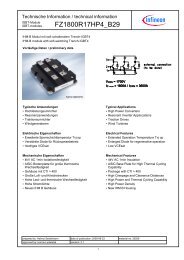
E51High voltage, <strong>low</strong> <strong>inductance</strong>, long-term safeoperationIn <strong>power</strong> electronics in general, but particularly in <strong>low</strong> <strong>inductance</strong> buffercircuits with higher voltages and in discharge circuits, the call for cap<strong>ac</strong>itorswith <strong>low</strong> <strong>inductance</strong> poses problems. Traditional high voltage cap<strong>ac</strong>itors arefilled with oil, and the generous bushings required for clearance/creepage aswell as internal safety mechanisms add substantially to the self-<strong>inductance</strong>of the cap<strong>ac</strong>itor.Based on decades of proprietary experience in metallizing cap<strong>ac</strong>itor <strong>film</strong>s,ELECTRONICON has created a range of high voltage cap<strong>ac</strong>itors in self-healingtechnology, using the opportunities of special metallizing patterns. Despitethe high voltage ratings, our E51 range is made in dry technology andwithout expensive bushings. For the sake of optimised self-<strong>inductance</strong>, theE51s are made without safety mechanism; by clever internal design they canbe laid out and rated in such manner that partial dielectric discharges an<strong>dc</strong>onsequential risk of failures in the customer’s application are reduced to aminimum.E53/E55All in one: High rms and surge currents combinedwith <strong>low</strong> self-<strong>inductance</strong>E51Hohe Spannungen, niedrige Induktivitäten,Langzeitbetrieb ohne AusfälleIn der Leistungselektronik im allgemeinen, speziell in niederinduktivenZwischenkreisen höherer Spannungen und in Entladeschaltungen ist dieForde<strong>ru</strong>ng n<strong>ac</strong>h niederinduktiven Kondensatoren mit Problemen verbunden:Traditionelle Hochspannungskondensatoren sind mit Öl gefüllt, und die fürdie Luft- und Kriechstrecken großzügig auszulegenden Anschlussisolatorenwie auch der interne Sicherheitsmechanismus tragen wesentlich zur Eigeninduktivitätdes Kondensators bei.Basierend auf jahrzehntelanger eigener Erfah<strong>ru</strong>ng bei der Metallisie<strong>ru</strong>ng vonKondensatorfolien hat ELECTRONICON unter Nutzung spezieller Metallisie<strong>ru</strong>ngsarteneine Reihe von Hochspannungskondensatoren in selbstheilenderTechnologie geschaffen. Trotz der hohen Spannungsnennwerte wird die E51Reihe in trockener Technologie und ohne aufwändige Anschlüsse gefertigt. ImInteresse einer optimierten niedrigen Eigeninduktivität werden die E51er ohneSicherheitsmechanismus gebaut; durch ein ausgeklügeltes Design könnensie so ausgelegt und bemessen werden, dass dielektrische Teilentladungenund das resultierende Ausfallrisiko in der Anwendung des Kunden auf einMinimum reduziert werden.E53/E55Alles in einem: hohe Effektiv- und SpitzenströmeUND geringe EigeninduktivitätBasically, the design of our E53 cap<strong>ac</strong>itors is very similar to E51. Usingsophisticated metallizing patterns, our SINECUT TM slitting technology, an<strong>dc</strong>lever winding geometries, the E53 series has a particularly <strong>low</strong> seriesresistance and high pulse strength. Therefore they are especially suited forthe damping of GTO thyristors and <strong>low</strong>-<strong>inductance</strong> buffer circuits with highrms currents. Their very <strong>low</strong> self-<strong>inductance</strong> makes them also suitable fo<strong>ru</strong>se in high-current applications with medium frequencies.Along with their very good ratio of cap<strong>ac</strong>itance to volume, the cap<strong>ac</strong>itors ofthe E51 and E53 product families do also have high pulse strength and verygood self-healing char<strong>ac</strong>teristics without loss or shift of cap<strong>ac</strong>itance. Thecap<strong>ac</strong>itors of our E55 series, which are very similar in design and electricalfeatures, have been optimized particularly for large cap<strong>ac</strong>itances at highoperating voltages.All the cap<strong>ac</strong>itors described above are housed in flame-retardant plastic cans(V0) and filled with solid resin. Special care has been taken both in terms ofdesign and conservative electrical rating to ensure reliable operation evenunder tough environmental conditions. Connection is usually made throughrobust axial terminals with internal thread. The E53H-range is based on thesame const<strong>ru</strong>ction and technology principles but al<strong>low</strong>s for radial connectionthrough robust studs with M8 thread; it has two br<strong>ac</strong>kets at the base of thecan which make for convenient mounting.Kondensatoren der E53-Reihe zeichnen sich durch einen besonders geringenSerienwiderstand und hohe Stoßstromfestigkeit aus. Durch die Nutzung einzigartigerMetallisie<strong>ru</strong>ngsmuster, unsere SINECUT Schneidtechnologie undausgeklügelte Wickelgeometrien eignen sie sich besonders zum Bedämpfenvon GTO-Thyristoren und in Zwischenkreisen mit hohen Effektivströmen. Ihresehr niedrige Eigeninduktivität ermöglicht darüber hinaus auch den Einsatz inHochstrom-Anwendungen im mittleren Frequenzbereich.Neben ihrem günstigen Verhältnis von Kapazität und Volumen zeichnen sichdie Kondensatoren der E51- und E53-Produktfamilien durch eine sehr hoheStoßstromfestigkeit und exzellente Selbstheilfähigkeit ohne Kapazitätsverlusteoder –verschiebungen aus. Die in Aufbau und Eigenschaften sehr ähnlichenE55-Kondensatoren sind auf große Kapazitäten bei gleichzeitig hohenSpannungswerten optimiert.Alle o.a. Kondensatoren sind in flammhemmenden Gehäusen (V0) untergebr<strong>ac</strong>htund mit Harz vergossen. Sowohl im Design als auch in der konservativenelektrischen Auslegung wurde großer Wert auf zuverlässiges Funktionierenauch unter schwierigen Umgebungsbedingungen gelegt. Der elektrischeAnschluss wird über robuste axiale Anschlüsse mit Innengewinde hergestellt.Die E53H-Reihe basiert auf gleichem Aufbau und technologischenPrinzipien, erlaubt jedoch einen radialen Anschluss mittels M8-Gewinde;2 Montagelaschen am Becherboden gewährleisten eine bequeme Befestigung.INTRODUCTION_EINLEITUNG5
E51.***DC1300...50000V DCAxial Low-<strong>inductance</strong> DC-Cap<strong>ac</strong>itors NiederinduktiveGleichspannungskondensatoren in axialer BauformLeL O WRSL O WStandards IEC 61071,optional IEC 61881can Gehäusemounting position Einbaulagefilling material Füllmittelplastic Kunststoff (UL94: VO)optional beliebigsolid, based on vegetable oil, non-PCBausgehärtet, auf Pflanzenölbasis, PCB-freiC Ntolerance Toleranz ±10% (optional ±5%)insulation strength Isolationsgüte C x R is 5000 stan 0 2 x10 -4operating temperatures Grenztemperaturen min ... max-25 ... +70°C HOTSPOT < 70°CInternal protectionInterne Siche<strong>ru</strong>ngfire load Brandlastnonekeine40 MJ/kgstoring temperature LagertemperaturFailure rate Ausfallrate-40 ... +85°C50 FITreference service period_Referenzbetriebsdauer 100000 h, HOTSPOT 70°U NDC C NU rU sU BBDC R thI maxÎ I SW NR SL eD 1x L 1m order no. pcs_Stk(V) (µF) (V) (V) (V) (K/W) (A) (kA) (kA) (Ws) (m) (nH) (mm) (kg) Bestell-Nr. / BoxDATA CHARTS_DATENTABELLEN_E51.***U N 1000V ... 2700V DC1300 700 300 1950 1950 3.0 80 9.3 28.0 592 0.39 30 140 x 175 2.8 E51.S18-704R20 2 / FB82300 80 400 4100 3795 3.6 50 4.0 13.0 212 1.3 80 64 x 355 1.2 E51.L35-803R20 10 / FB112300 170 400 4100 3450 2.4 90 6.0 17.0 450 0.6 100 90 x 355 2.4 E51.P35-174R20 5 / FB112500 25 800 3750 3750 6.4 70 3.1 9.3 78 0.96 30 90 x 130 0.9 E51.P13-253R20 10 / FB92500 50 800 3750 3750 4.9 70 3.1 9.3 156 1.3 50 90 x 170 1.1 E51.P17-503R20 5 / FB82700 40 500 4050 4455 2.55 40 5.0 15.0 146 0.85 20 140 x 125 2.0 E51.S12-403R20 4 / FB9U N 3000V ... 3600V DC3000 18 600 4500 4500 5.5 65 2.8 8.4 81 0.62 50 90 x 150 1.1 E51.P15-183R20 10 / FB103000 80 700 4500 4500 3.2 60 3.2 9.6 360 1.9 60 90 x 255 1.7 E51.P25-803R20 5 / FB93000 350 600 4500 4500 1.5 75 8.4 25.2 1575 1.5 100 140 x 355 5.7 E51.S35-354R20 2 / FB93000 400 600 4500 4500 1.2 100 15.4 46.2 1800 0.85 120 140 x 460 7.4 E51.S46-404R20 10 / FB263100 86 500 5600 5115 2.4 65 4.5 13.0 413 1.5 100 90 x 355 2.4 E51.P35-863R20 5 / FB113200 15 700 4800 5280 5.8 35 1.0 3.0 77 2.3 50 64 x 200 0.7 E51.L20-153R20 10 / FB83200 33 700 4800 5280 4.1 70 2.5 7.5 169 0.7 50 90 x 200 1.3 E51.P20-333R20 5 / FB83500 500 600 5250 5250 0.75 100 13.9 41.7 3063 1.2 200 140 x 710 11.5 E51.S71-504R20 5 / FB253600 80 600 5400 5940 2.6 90 6.0 18.0 518 0.71 40 116 x 245 2.1 E51.R24-803R20 3 / FB123600 220 800 5400 5400 1.1 40 4.4 13.2 1426 0.6 40 140 x 300 5.0 E51.S30-224R20 2 / FB9U N 4000V ... 5600V DC4000 8.0 2850 6000 6000 3.8 25 2.1 6.3 64 1.4 100 116 x 170 1.9 E51.R17-802R20 3 / FB84000 16 2850 6000 6000 3.1 30 3.8 11.4 128 1.1 100 140 x 170 2.7 E51.S17-163R20 2 / FB84000 215 800 6000 6000 0.95 100 11.9 35.7 1720 0.7 60 140 x 565 9.0 E51.S56-224R20 4 / FB224200 8.0 800 6300 6930 8.3 15 0.69 2.07 71 4.3 60 64 x 138 0.5 E51.L14-802R20 10 / FB04200 45 800 6300 6930 2.4 50 4.2 12.6 397 1.6 80 90 x 355 2.4 E51.P35-453R20 5 / FB114400 8.0 950 6600 6600 6.5 20 0.85 2.55 77 4.2 60 64 x 180 0.6 E51.L18-802R20 10 / FB84400 8.0 950 6600 6600 6.4 20 1.7 5.1 77 1.4 50 90 x 130 0.9 E51.P13-802R20 10 / FB94500 300 850 6750 6750 0.75 100 16.5 49.5 3038 1.1 200 140 x 710 11.5 E51.S71-304R20 5 / FB254700 187.5 1000 7050 7050 0.7 50 4.25 12.75 2071 3.2 40 140 x 430 7.0 E51.S43-194R20 10 / FB265000 4.55 1000 7500 7500 7.8 15 0.47 1.41 57 6.5 60 64 x 150 0.5 E51.L15-462R20 10 / FB05600 1.0 1100 8400 8400 9.7 20 0.7 2.2 16 4.6 20 64 x 120 1.0 E51.L12-102R20 10 / FB06Other values and dimensions available on request_Andere Werte und Abmessungen auf Anfrage erhältlich
E51.***DC1300...50000V DCU NDC C NU rU sU BBDC R thI maxÎ I SW NR SL eD 1x L 1m order no. pcs_Stk(V) (µF) (V) (V) (V) (K/W) (A) (kA) (kA) (Ws) (m) (nH) (mm) (kg) Bestell-Nr. / BoxU N 6000V ... 9300V DC6000 30 700 9000 9000 3.2 30 2.1 6.3 540 2.3 80 116 x 200 2.2 E51.R20-303R20 3 / FB86200 6.8 1200 9300 9300 4.6 20 0.6 2.0 131 10 50 64 x 255 0.9 E51.L25-682R20 10 / FB96200 15 1200 9300 9300 3.2 35 1.5 4.5 288 4.6 50 90 x 255 1.7 E51.P25-153R20 5 / FB96300 20 1200 9450 9450 2.4 25 1.8 8.0 397 6.8 100 90 x 355 2.4 E51.P35-203R20 5 / FB116300 51.25 1200 9450 9450 1.5 40 4.3 20.0 1017 2.7 80 140 x 355 5.7 E51.S35-513R20 2 / FB97200 1.0 1300 10800 10800 6.4 25 1.1 3.3 26 3.3 30 90 x 130 0.9 E51.P13-102R21 10 / FB98000 5.0 1400 12000 12000 3.76 50 1.8 5.0 160 1.7 80 90 x 220 1.5 E51.P22-502R20 5 / FB88000 10 1400 12000 12000 2.59 50 1.9 6.0 320 2.3 100 90 x 320 2.2 E51.P32-103R20 5 / FB128000 40 1400 12000 12000 1.5 40 2.7 8.1 1280 3.5 100 140 x 355 5.7 E51.S35-403R20 2 / FB98500 0.22 1400 12750 12750 7.1 20 0.9 2.9 8 6.9 50 64 x 165 0.6 E51.L16-221R20 10 / FB78500 0.5 1400 12750 12750 7.1 20 0.7 2.0 18 7.9 50 64 x 165 0.6 E51.L16-501R20 10 / FB78500 1.0 1400 12750 12750 5.0 25 1.7 5.1 36 2.5 50 90 x 165 1.1 E51.P16-102R20 5 / FB79300 9.0 1500 13950 13950 2.3 20 1.0 4.0 389 8.0 100 90 x 355 2.4 E51.P35-902R20 5 / FB119300 25 1500 13950 13950 1.5 40 4.0 11.0 1081 2.7 100 140 x 355 5.7 E51.S35-253R20 2 / FB9U N 10000V ... 50000V DC10000 0.25 2000 15000 15000 7.1 10 1.1 3.3 13 15.2 80 64 x 165 0.6 E51.L16-251R20 10 / FB710000 4.0 2000 15000 15000 2.0 50 1.5 4.5 200 3.5 60 116 x 320 3.5 E51.R32-402R20 3 / FB1010000 4.5 3000 15000 15000 1.1 50 8.8 26.4 225 1.8 100 140 x 480 8.0 E51.S48-452R20 4 / FB2210000 10 2500 15000 15000 2.3 25 1.3 3.9 500 7.0 100 90 x 355 2.4 E51.P35-103R20 5 / FB1112000 24 2100 18000 18000 0.95 25 4.2 12.6 1728 4.2 60 140 x 565 9.0 E51.S56-243R20 4 / FB2212500 0.22 2100 18750 18750 5.8 20 0.5 1.4 17 14 80 64 x 200 0.7 E51.L20-221R20 10 / FB812500 0.25 2100 18750 18750 5.8 20 0.5 1.5 20 14 80 64 x 200 0.7 E51.L20-251R20 10 / FB812500 0.5 2100 18750 18750 4.1 25 1.1 3.3 39 6.3 80 90 x 200 1.3 E51.P20-501R20 5 / FB812500 1.0 2100 18750 18750 3.2 35 2.0 6.0 78 3.6 80 116 x 200 2.2 E51.R20-102R20 3 / FB813000 0.25 3000 19500 19500 4.1 10 0.6 1.7 21 17.7 100 64 x 285 1.0 E51.L28-251R20 10 / FB1214000 5.0 2400 21000 21000 1.8 30 2.5 7.5 563 3.6 100 116 x 355 4.0 E51.R35-502R20 3 / FB1114000 10 2400 21000 21000 1.5 40 4.3 12.9 980 2.4 120 140 x 355 5.7 E51.S35-103R20 2 / FB915000 1.0 3600 22500 22500 4.1 15 0.49 1.47 113 15.1 100 60 x 285 1.0 E51.L28-102R20 10 / FB1215000 2.0 3600 22500 22500 2.9 20 1.1 3.3 225 7.2 200 90 x 285 1.9 E51.P28-202R20 5 / FB1215000 10 3600 22500 22500 1.4 40 3.8 11.4 1125 2.7 120 140 x 385 6.2 E51.S38-103R20 10 / FB2615000 15 3600 22500 22500 1.2 40 4.6 13.8 1688 2.8 120 140 x 460 7.4 E51.S46-153R20 4 / FB2215000 20 3600 22500 22500 0.94 40 3.8 11.4 2250 3.7 120 140 x 565 9.1 E51.S56-203R20 4 / FB2220000 1.25 4000 30000 30000 2.3 20 0.9 2.7 250 11.7 100 90 x 355 2.4 E51.P35-132R20 5 / FB1120000 1.5 4000 30000 30000 2.3 34 1.8 5.4 300 10.4 100 90 x 355 2.4 E51.P35-152R20 5 / FB1125000 10 4600 37500 37500 0.75 35 4.3 12.9 3125 3.9 200 140 x 710 11.5 E51.S71-103R20 5 / FB2530000 1.0 4800 45000 45000 1.9 20 1.0 3.0 450 11.0 80 90 x 435 2.9 E51.P44-102R20 6 / FB2330000 5.0 4800 45000 45000 0.75 35 2.8 8.4 2250 7.0 200 140 x 710 11.5 E51.S71-502R20 5 / FB2535000 0.2 5600 52500 52500 1.9 20 1.0 3.0 123 13.4 80 90 x 435 2.9 E51.P44-201R20 6 / FB2335000 5.0 4800 52500 52500 0.7 25 3.2 9.6 3063 5.5 200 140 x 785 12.7 E51.S78-502R20 4 / FB2540000 2.2 8700 60000 52500* 0.84 35 2.8 8.4 1760 5.3 180 140 x 630 10.2 E51.S63-222R20 5 / FB2550000 2.0 10000 60000 52500** 0.75 35 2.9 8.7 2500 5.8 200 140 x 710 11.5 E51.S71-501R20 5 / FB25* additional test_Zusatzprüfung 14500V rms/10s** additional test_Zusatzprüfung 16500V rms/10sDATA CHARTS_DATENTABELLEN_E51.***Other values and dimensions available on request_Andere Werte und Abmessungen auf Anfrage erhältlich7
E51.***AC/DC2350...35000V AC / 3200...50000V DCAxial Low-<strong>inductance</strong> AC/DC-Cap<strong>ac</strong>itors NiederinduktiveWechsel-/Gleichspannungskondensatoren in axialer BauformLeL O WRSL O WStandards IEC 61071,optional IEC 61881can Gehäusemounting position Einbaulagefilling material Füllmittelplastic Kunststoff (UL94: VO)optional beliebigsolid, based on vegetable oil, non-PCBausgehärtet, auf Pflanzenölbasis, PCB-freiC Ntolerance Toleranz ±10% (optional ±5%)insulation strength Isolationsgüte C x R is 5000 stan 0 2 x10 -4operating temperatures Grenztemperaturen min ... max-25 ... +70°C HOTSPOT < 70°CInternal protectionInterne Siche<strong>ru</strong>ngfire load Brandlastnonekeine40 MJ/kgstoring temperature LagertemperaturFailure rate Ausfallrate-40 ... +85°C100 FITreference service period_Referenzbetriebsdauer 100000 h, HOTSPOT 70°U NAC U NDC C NU rmsU sU BBR thI maxÎ I SW NR SL eD 1x L 1m order no. pcs_Stk(V) (V) (µF) (V) (V) (V) (K/W) (A) (kA) (kA) (Ws) (m) (nH) (mm) (kg) Bestell-Nr. / BoxDATA CHARTS_DATENTABELLEN_E51.***U N 2000V ... 2550V AC2350 4500 1.5 1650 6750 6750 (DC) 7.8 20 0.7 2.0 15.2 5.4 20 64 x 150 0.5 E51.L15-152R20 10 / FB02350 3.0 1650 3525 5053 4.7 15 1.1 3.3 8.3 3.0 60 64 x 250 1.0 E51.L25-302R20 10 / FB92550 3200 1.0 1800 4800 4800 9.7 40 2.0 5.0 5.1 1.8 40 64 x 120 0.4 E51.L12-102R20 10 / FB0U N 3000V ... 3850V AC3000 0.47 2100 6450 6450 (DC) 11.6 15 1.1 3.3 2.1 3.2 60 64 x 100 0.3 E51.L10-471R20 10 / FB13000 5.0 2200 7000 5000 (AC) 2.5 10 2.0 6.0 22.5 3.8 80 116 x 260 2.9 E51.R26-502R20 3 / FB123250 0.75 2300 4875 4875 (AC) 7.1 20 0.9 2.8 4.0 4.9 100 64 x 165 0.6 E51.L16-751R20 10 / FB73500 6000 0.22 2500 9000 9000 (DC) 9.7 20 0.7 2.1 4.0 4.8 60 64 x 120 0.4 E51.L12-221R20 10 / FB03500 6000 0.25 2500 9000 9000 (DC) 9.7 15 0.8 2.4 4.5 5.4 60 64 x 120 0.4 E51.L12-251R20 10 / FB03500 6000 0.33 2500 9000 9000 (DC) 9.7 20 1.0 2.9 5.9 3.0 60 64 x 120 0.4 E51.L12-331R20 10 / FB03500 6000 0.5 2500 9000 9000 (DC) 9.7 20 1.0 3.0 9.0 5.6 60 64 x 120 0.4 E51.L12-501R20 10 / FB03500 6000 0.68 2500 9000 9000 (DC) 9.7 20 1.0 2.9 12.2 4.6 60 64 x 120 0.4 E51.L12-681R20 10 / FB03850 2.5 2700 5775 7700 (DC) 2.9 25 2.0 6.0 18.5 4.1 100 90 x 285 1.9 E51.P28-252R20 5 / FB12U N 4000V ... 4700V AC4000 5000 3.0 1750 7500 9460 (DC) 5.8 80 2.0 6.0 37.5 0.74 15 116 x 110 1.2 E51.R11-302R20 6 / FB104000 5000 4.0 1750 7500 8600 (DC) 5.8 90 2.2 7.0 50 0.62 15 116 x 110 1.2 E51.R11-402R20 6 / FB104200 0.6 3000 6300 9030 (DC) 7.8 18 0.5 1.4 5.3 7.9 60 64 x 150 0.5 E51.L15-601R20 10 / FB04200 1.1 3000 6300 9030 (DC) 5.5 20 1.6 4.8 9.7 2.7 50 90 x 150 1.0 E51.P15-112R20 10 / FB104300 0.5 3050 6450 9245 (DC) 7.1 15 0.8 2.3 4.6 5.3 100 64 x 165 0.6 E51.L16-501R20 10 / FB74300 0.8 3050 6450 9245 (DC) 5.8 15 0.9 2.7 7.4 7.5 100 64 x 200 0.7 E51.L20-801R20 10 / FB84550 1.1 3200 6825 6880 (AC) 3.0 20 2.4 7.2 11.4 3.6 80 90 x 275 1.9 E51.P27-112R20 5 / FB124550 2.2 3200 6825 6880 (AC) 2.0 25 4.5 13.5 22.8 2.3 100 116 x 320 3.5 E51.R32-222R20 3 / FB124700 0.75 3300 7050 4460 (AC) 4.7 15 0.9 2.7 8.3 7.5 60 64 x 250 1.0 E51.L25-751R20 10 / FB94700 1.5 3300 11000 6600 (AC) 1.8 25 3.0 10.0 16.6 4.2 120 116 x 355 3.9 E51.R35-152R20 3 / FB11U N 5000V ... 5850V AC5000 0.47 3500 10750 10750 (DC) 5.5 16 1.0 3.0 5.9 5.8 40 64 x 210 0.8 E51.L21-471R20 10 / FB85000 7000 1.5 3500 10500 10750 (DC) 5.5 25 1.0 3.0 36.8 2.3 50 90 x 150 1.0 E51.P15-152R20 10 / FB105100 1.6 3600 9500 7100 (AC) 1.8 25 5.0 15.0 20.8 4.,0 120 116 x 355 3.9 E51.R35-162R20 3 / FB118Other values and dimensions available on request_Andere Werte und Abmessungen auf Anfrage erhältlich
E51.***AC/DC2350...35000V AC / 3200...50000V DCU NAC U NDC C NU rmsU sU BBR thI maxÎ I SW NR SL eD 1x L 1m order no. pcs_Stk(V) (V) (µF) (V) (V) (V) (K/W) (A) (kA) (kA) (Ws) (m) (nH) (mm) (kg) Bestell-Nr. / BoxU N 5000V ... 5850V AC5100 2.4 3600 10965 10965 (DC) 4.1 35 1.4 4.2 31.2 3.0 60 90 x 200 1.3 E51.P20-242R21 5 / FB85100 2.6 3600 9500 7100 (AC) 1.4 25 5.0 15 33.8 3.8 120 116 x 460 4.9 E51.R46-262R20 6 / FB235200 1.1 3700 7800 11180 (DC) 4.1 20 5.1 3.1 14.9 3.1 60 90 x 200 1.3 E51.P20-112R20 5 / FB85850 0.47 4150 12580 12580 (DC) 5.0 20 2.2 6.6 8.0 3.5 60 90 x 165 1.2 E51.P16-471R20 5 / FB8U N 6000V ... 9620V AC6300 9000 0.13 13500 13545 (DC) 7.1 20 0.8 2.4 5.1 5.5 100 64 x 165 0.6 E51.L16-131R20 10 / FB76300 9000 0.14 13500 13545 (DC) 5.8 14 0.3 0.9 5.7 17.6 50 64 x 200 0.7 E51.L20-141R20 10 / FB86500 4.0 4600 9500 14000 (DC) 1.5 12 7.0 21.0 84.5 1.7 150 140 x 355 5.7 E51.S35-402R20 2 / FB98000 10000 0.5 5600 17200 17200 (DC) 4.1 25 1.0 3.0 25.0 5.7 50 90 x 200 1.3 E51.P20-501R20 5 / FB88000 1.0 5600 17200 17200 (DC) 4.1 25 1.2 3.6 32.0 5.8 50 90 x 255 1.7 E51.P25-102R20 5 / FB98900 0.24 6300 13350 19200 (DC) 3.94 20 2.0 6.0 9.5 5.0 60 90 x 210 1.4 E51.P21-241R20 5 / FB89620 0.5 6800 14430 10200 (AC) 2.6 40 3.7 11.1 23.1 3.0 60 116 x 250 2.9 E51.R25-501R20 3 / FB9U N 10000V ... 35000V AC10000 14000 1.0 7100 15000 8875 (AC) 1.7 25 3.7 11.1 98.0 3.4 100 116 x 390 4.0 E51.R39-102R20 6 / FB2310000 14000 1.9 7100 15000 8875 (AC) 1.4 25 6.2 18.6 186.2 2.1 100 140 x 390 6.0 E51.S39-192R20 10 / FB2612750 0.2 9000 27400 27400 (DC) 2.3 20 2.3 6.9 16.3 7.0 100 90 x 355 2.4 E51.P35-201R20 5 / FB1114000 0.5 10000 21000 21000 (AC) 3.0 10 1.7 5.1 49.0 3.9 80 90 x 275 1.9 E51.P27-501R20 5 / FB1214000 1.33 10000 21000 21000 (DC) 1.5 10 2.5 7.5 130.3 3.9 100 140 x 355 5.7 E51.S35-132R20 2 / FB917000 0.5 12000 25000 29400 (DC) 1.4 10 1.0 3.0 72.3 7.2 100 90 x 355 2.4 E51.P35-501R20 5 / FB1120000 26000 0.3 14000 30000 43000 (DC) 1.8 10 8.0 20.0 101.4 3.1 100 116 x 355 3.9 E51.R35-301R20 3 / FB1125000 30000 1.0 17700 45000 52500 (DC) 0.7 10 4.9 14.7 450.0 5.7 200 140 x 710 11.5 E51.S71-102R20 5 / FB2535000 50000 0.5 25000 60000 50000 (AC) 0.8 10 8.5 20.0 625.0 6.2 200 140 x 710 11.5 E51.S71-501R20 5 / FB25DATA CHARTS_DATENTABELLEN_E51.***Other values and dimensions available on request_Andere Werte und Abmessungen auf Anfrage erhältlich9
E53.***AC/DC280...2450V AC / 550...7200V DCAxial Low-<strong>inductance</strong> AC/DC-Cap<strong>ac</strong>itors NiederinduktiveWechsel-/Gleichspannungskondensatoren in axialer BauformLeL O WRSL O WH I G HH I G HStandards IEC 61071,optional IEC 61881can Gehäusemounting position Einbaulagefilling material FüllmittelInternal protectionInterne Siche<strong>ru</strong>ngfire load Brandlastplastic Kunststoff (UL94: VO)optional beliebigsolid, based on vegetable oil, non-PCBausgehärtet, auf Pflanzenölbasis, PCB-freinonekeine40 MJ/kgC Ntolerance Toleranz ±10% (optional ±5%)self-<strong>inductance</strong> Eigeninduktivität L eca. 15 nHinsulation strength Isolationsgüte C x R is 5000 stan 0 2 x10 -4operating temperatures Grenztemperaturen min ... max-25 ... +85°C HOTSPOT < 85°Cstoring temperature Lagertemperatur-40 ... +85°CFailure rate Ausfallratereference service period_Referenzbetriebsdauer 100000 h, HOTSPOT 70°100 FITC NR SL eR thI maxÎ I SW ND 1x L 1Design m L/K order no. pcs_Stk(µF) (m) (nH) (K/W) (A) (kA) (kA) (Ws) (mm) Maßbild (kg) (mm) Bestell-Nr. / BoxDATA CHARTS_DATENTABELLEN_E53.***U N 550V DC / 280V AC U rms 200V US 825V UBB 825V DC50 0.8 15 8.1 60 0.83 2.5 8.0 55 x 59 T1 0.19 95/100 E53.H59-503T10 15 / FB6100 0.4 15 5.9 80 1.7 5.0 15 75 x 59 T2 0.35 109/114 E53.M59-104T20 10 / FB2200 0.2 15 4.7 80 3.3 9.9 30 95 x 59 T2 0.55 129/134 E53.P59-204T20 10 / FB2250 0.15 15 4.2 80 3.3 10.0 38 105 x 59 T2 0.67 139/144 E53.Q59-254T20 10 / FB2U N 700V DC / 350V AC U rms 250V US 1050V UBB 1050V DC33 0.95 15 8.1 55 0.68 2.1 8.0 55 x 59 T1 0.19 95/100 E53.H59-333T10 15 / FB668 0.5 15 5.9 80 1.4 4.2 17 75 x 59 T2 0.35 109/114 E53.M59-683T20 10 / FB2120 0.3 15 4.7 80 2.5 7.4 29 95 x 59 T2 0.55 129/134 E53.P59-124T20 10 / FB2150 0.25 15 4.2 100 3.1 9.3 37 105 x 59 T2 0.67 139/144 E53.Q59-154T20 10 / FB2200 0.2 15 3.8 100 3.1 10.0 49 115 x 60 T2 0.82 150/155 E53.R60-204T20 12 / FB9310 0.3 15 2.1 100 3.0 10.0 76 115 x 110 T2 1.5 200/205 E53.R11-314T20 6 / FB8U N 900V DC / 350V AC U rms 250V US 1350V UBB 1350V DC30 0.85 15 8.1 60 0.68 2.1 12 55 x 59 T1 0.19 95/100 E53.H59-303T10 15 / FB660 0.5 15 5.9 80 1.4 4.1 24 75 x 59 T2 0.35 109/114 E53.M59-603T20 10 / FB2100 0.35 15 4.7 80 2.3 6.8 41 95 x 59 T2 0.55 129/134 E53.P59-104T20 10 / FB2120 0.2 15 4.2 100 2.8 9.0 49 105 x 59 T2 0.67 139/144 E53.Q59-124T20 10 / FB2140 0.2 15 3.8 100 3.1 10.0 57 115 x 60 T2 0.82 150/155 E53.R60-144T20 12 / FB9265 0.35 15 2.1 100 3.0 9.0 107 115 x 110 T2 1.5 200/205 E53.R11-274T20 6 / FB8U N 1100V DC / 350V AC U rms 250V US 1650V UBB 1650V DC12 1.7 15 8.1 40 0.40 1.2 7.0 55 x 59 T1 0.19 95/100 E53.H59-123T10 15 / FB615 1.1 15 8.1 40 0.5 1.5 9.0 55 x 59 T1 0.19 95/100 E53.H59-153T10 15 / FB625 0.71 15 5.9 70 0.83 2.5 15 75 x 59 T2 0.35 109/114 E53.M59-253T20 10 / FB250 0.34 15 4.7 80 1.7 5.0 30 95 x 59 T2 0.55 129/134 E53.P59-503T20 10 / FB260 0.35 15 4.2 100 2.0 6.0 36 105 x 59 T2 0.67 139/144 E53.Q59-603T20 10 / FB280 0.21 15 3.8 100 3.0 10.0 48.4 115 x 60 T2 0.82 150/155 E53.R60-803T20 12 / FB9175 0.41 15 2.1 100 2.6 8.0 106 115 x 110 T2 1.50 200/205 E53.R11-184T20 6 / FB810Other values and dimensions available on request_Andere Werte und Abmessungen auf Anfrage erhältlich
E53.***AC/DC280...2450V AC / 550...7200V DCC NR SL eR thI maxÎ I SW ND 1x L 1Design m L/K order no. pcs_Stk(µF) (m) (nH) (K/W) (A) (kA) (kA) (Ws) (mm) Maßbild (kg) (mm) Bestell-Nr. / BoxU N 1400V DC / 350V AC U rms 250V US 2100V UBB 2100V DC8.0 2.0 15 8.1 38 0.33 1.0 8.0 55 x 59 T1 0.19 95/100 E53.H59-802T10 15 / FB616 1.0 15 5.9 60 0.66 2.0 16 75 x 59 T2 0.35 109/114 E53.M59-163T20 10 / FB230 0.55 15 4.7 80 1.2 3.7 29 95 x 59 T2 0.55 129/134 E53.P59-303T20 10 / FB240 0.4 15 4.2 100 1.7 5.0 39 105 x 59 T2 0.67 139/144 E53.Q59-403T20 10 / FB250 0.3 15 3.8 100 2.2 10.0 49 115 x 60 T2 0.82 150/155 E53.R60-503T20 12 / FB9110 0.52 15 2.1 100 2.0 6.0 108 115 x 110 T2 1.50 200/205 E53.R11-114T20 6 / FB8U N 1700V DC / 700V AC U rms 500V US 2550V UBB 2550V DC4.7 1.3 15 8.1 45 0.5 1.6 7.0 55 x 59 T1 0.19 95/100 E53.H59-472T10 15 / FB610 0.6 15 5.9 80 1.1 3.5 14 75 x 59 T2 0.35 109/114 E53.M59-103T20 10 / FB216 0.37 15 4.7 80 1.8 5.5 23 95 x 59 T2 0.55 129/134 E53.P59-163T20 10 / FB222 0.27 15 4.2 100 2.5 7.5 32 105 x 59 T2 0.67 139/144 E53.Q59-223T20 10 / FB233 0.2 15 3.8 100 3.5 10.0 48 115 x 60 T2 0.82 150/155 E53.R60-333T20 12 / FB968 0.35 15 2.1 100 3.1 9.3 98 115 x 110 T2 1.50 200/205 E53.R11-683T20 6 / FB8U N 2000V DC / 700V AC U rms 500V US 3000V UBB 3000V DC3.3 1.6 15 8.1 40 0.42 1.2 7.0 55 x 59 T1 0.19 95/100 E53.H59-332T10 15 / FB68.0 0.65 15 5.9 80 1.0 3.0 16 75 x 59 T2 0.35 109/114 E53.M59-802T20 10 / FB214 0.35 15 4.7 80 1.8 5.5 28 95 x 59 T2 0.55 129/134 E53.P59-143T20 10 / FB218 0.3 15 4.2 100 2.3 7.0 36 105 x 59 T2 0.67 139/144 E53.Q59-183T20 10 / FB224 0.2 15 3.8 100 3.0 10.0 48 115 x 60 T2 0.82 150/155 E53.R60-243T20 12 / FB952.2 0.39 15 2.1 100 2.8 8.0 105 115 x 110 T2 1.50 200/205 E53.R11-533T20 6 / FB8U N 2250V DC / 700V AC U rms 500V US 3375V UBB 3375V DC2.5 1.8 15 8.1 40 0.37 1.1 6.0 55 x 59 T1 0.19 95/100 E53.H59-252T10 15 / FB66.0 0.76 15 5.9 70 0.88 2.6 15 75 x 59 T2 0.35 109/114 E53.M59-602T20 10 / FB210 0.46 15 4.7 80 1.5 4.5 25 95 x 59 T2 0.55 129/134 E53.P59-103T20 10 / FB212 0.37 15 4.2 100 2.5 7.0 30 105 x 59 T2 0.64 139/144 E53.Q59-123T20 10 / FB214 0.33 15 4.2 100 2.0 6.0 35 105 x 59 T2 0.67 139/144 E53.Q59-143T20 10 / FB215 0.27 15 4.2 100 2.1 6.2 38 105 x 59 T2 0.67 139/144 E53.Q59-153T20 10 / FB218 0.25 15 3.8 100 2.6 10.0 46 115 x 60 T2 0.82 150/155 E53.R60-183T20 12 / FB940 0.45 15 2.1 100 2.4 7.0 101 115 x 110 T2 1.50 200/205 E53.R11-403T20 6 / FB8U N 2800V DC / 700V AC U rms 500V US 4200V UBB 4200V DC1.5 2.4 15 8.1 32 0.27 0.27 6.0 55 x 59 T1 0.19 95/100 E53.H59-152T10 15 / FB63.3 1.1 15 5.9 60 0.6 3.0 13 75 x 59 T2 0.35 109/114 E53.M59-332T20 10 / FB25.0 0.42 15 4.7 80 2.0 6.0 20 95 x 59 T2 0.55 129/134 E53.P59-502T20 10 / FB26.8 0.55 15 4.7 80 1.2 6.0 27 95 x 59 T2 0.55 129/134 E53.P59-682T20 10 / FB27.5 0.5 15 4.7 80 1.5 7.5 29 95 x 59 T2 0.55 129/134 E53.P59-752T20 10 / FB28.0 0.45 15 4.2 100 1.5 7.5 31 105 x 59 T2 0.67 139/144 E53.Q59-802T20 10 / FB210 0.4 15 4.2 100 1.8 9.0 39 105 x 59 T2 0.67 139/144 E53.Q59-103T20 10 / FB2DATA CHARTS_DATENTABELLEN_E53.***Other values and dimensions available on request_Andere Werte und Abmessungen auf Anfrage erhältlich11
E53.***AC/DC280...2450V AC / 550... 7200V DCC NR SL eR thI maxÎ I SW ND 1x L 1Design m L/K order no. pcs_Stk(µF) (m) (nH) (K/W) (A) (kA) (kA) (Ws) (mm) Maßbild (kg) (mm) Bestell-Nr. / BoxU N 2800V DC / 700V AC U rms 500V US 4200V UBB 4200V DC12 0.3 15 3.8 100 2.2 12.0 47 115 x 60 T2 0.82 150/155 E53.R60-123T20 12 / FB925 0.57 15 2.1 100 1.9 6.0 98 115 x 110 T2 1.5 200/205 E53.R11-253T20 6 / FB8U N 3200V DC / 1050V AC U rms 750V US 4800V UBB 4800V DC1.0 1.6 15 8.1 40 0.35 1.8 5.0 55 x 59 T1 0.19 95/100 E53.H59-102T10 15 / FB62.5 0.65 15 5.9 75 0.9 4.5 13 75 x 59 T2 0.35 109/114 E53.M59-252T20 10 / FB23.0 0.54 15 4.7 80 1.2 3.6 15 95 x 59 T2 0.55 129/134 E53.P59-302T20 10 / FB24.0 0.4 15 4.7 80 1.5 7.5 20 95 x 59 T2 0.55 129/134 E53.P59-402T20 10 / FB24.5 0.4 15 4.2 100 1.6 8.0 23 105 x 59 T2 0.67 139/144 E53.Q59-452T20 10 / FB25.0 0.32 15 4.2 100 1.8 9.0 26 105 x 59 T2 0.67 139/144 E53.Q59-502T20 10 / FB26.0 0.28 15 4.2 100 2.2 11.0 31 105 x 59 T2 0.67 139/144 E53.Q59-602T20 10 / FB27.0 0.25 15 3.8 100 3.0 12.0 36 115 x 60 T2 0.82 150/155 E53.R60-702T20 12 / FB9U N 2450V DC /1400V AC U rms 1000V US 3675V UBB 3675V DC1.16 1.2 15 8.1 20 0.7 2.2 1.1 55 x 59 T1 0.19 95/100 E53.H59-122T10 15 / FB62.4 0.56 15 5.9 60 1.5 5.0 2.4 75 x 59 T2 0.35 109/114 E53.M59-242T20 10 / FB24.2 0.32 15 4.7 80 2.6 8.0 4.1 95 x 59 T2 0.55 129/134 E53.P59-422T20 10 / FB25.2 0.26 15 4.2 100 3.0 10.0 5.1 105 x 59 T2 0.67 139/144 E53.Q59-522T20 10 / FB26.4 0.21 15 3.8 100 4.0 12.0 6.3 115 x 60 T2 0.82 150/155 E53.R60-642T20 12 / FB9U N 3600V DC / 1400V AC U rms 1000V US 5400V UBB 5400V DC8.0 0.52 15 2.1 100 2.3 6.9 52 115 x 110 T2 1.50 200/205 E53.R11-802T20 6 / FB810 0.94 15 2.1 100 2.5 7.5 65 115 x 110 T2 1.50 200/205 E53.R11-103T20 6 / FB8U N 3750V DC / 2100V AC U rms 1500V US 5625V UBB 5625V DCDATA CHARTS_DATENTABELLEN_E53.***0.47 2.9 15 8.1 20 0.7 2.1 1.0 55 x 59 T1 0.19 95/100 E53.H59-471T10 15 / FB61.1 1.2 15 5.9 60 1.6 5.0 2.4 75 x 59 T2 0.35 109/114 E53.M59-112T20 10 / FB21.7 0.8 15 4.7 80 2.5 8.0 3.7 95 x 59 T2 0.55 129/134 E53.P59-172T20 10 / FB22.15 0.64 15 4.2 100 3.0 10.0 4.7 105 x 59 T2 0.67 139/144 E53.Q59-222T20 10 / FB22.7 0.51 15 3.8 100 4.0 12.0 6.0 115 x 60 T2 0.82 150/155 E53.R60-272T20 12 / FB9U N 5000V DC / 2100V AC U rms 1500V US 7500V UBB 7500V DC3.0 1.2 15 2.1 125 2.1 6.3 38 115 x 110 T2 1.50 200/205 E53.R11-302T21 6 / FB84.0 1.0 15 2.1 125 2.5 7.5 50 115 x 110 T2 1.50 200/205 E53.R11-402T20 6 / FB8U N 5600V DC / 2450V AC U rms 1750V US 8400V UBB 8400V DC0.22 13.7 15 4.9 25 0.2 0.7 3.0 55 x 97 T1 0.31 138 E53.H97-221T10 18 / FB30.25 12.1 15 4.9 25 0.3 0.8 4.0 55 x 97 T1 0.32 138 E53.H97-251T10 18 / FB30.5 8.0 15 4.9 25 0.4 1.3 8.0 55 x 97 T1 0.33 138 E53.H97-501T10 18 / FB3U N 7200V DC / 2450V AC U rms 1750V US 10800V UBB 10800V DC0.22 13.7 15 4.9 25 0.2 0.7 6.0 55 x 97 T1 0.31 138 E53.H97-221T10 18 / FB30.25 12.1 15 4.9 25 0.3 0.8 6.0 55 x 97 T1 0.32 138 E53.H97-251T10 18 / FB30.5 11.0 15 3.6 20 0.4 1.1 13.0 55 x 131 T1 0.41 172 E53.H13-501T10 18 / FB112Other values and dimensions available on request_Andere Werte und Abmessungen auf Anfrage erhältlich
E53.*** H/E55.***DC500...5000V DCH I G HH I G HLow-<strong>inductance</strong> DC-Cap<strong>ac</strong>itorsNiederinduktive GleichspannungskondensatorenLeL O WRSL O WStandards IEC 61071,optional IEC 61881can Gehäusemounting position Einbaulagefilling material Füllmittelplastic Kunststoff (UL94: VO)optional beliebigsolid, based on vegetable oil, non-PCBausgehärtet, auf Pflanzenölbasis, PCB-freiC Ntolerance Toleranz ±10% (optional ±5%)insulation strength Isolationsgüte C x R is 5000 stan 0 2 x10 -4operating temperatures Grenztemperaturen min ... max-25 ... +85°C HOTSPOT < 85°CInternal protectionInterne Siche<strong>ru</strong>ngfire load Brandlastnonekeine40 MJ/kgstoring temperature LagertemperaturFailure rate Ausfallrate-40 ... +85°C50 FITreference service period_Referenzbetriebsdauer 100000 h, HOTSPOT 70°C NU rR thI maxÎ I SW NR SL eD 1x L 1Design m L/K order no. pcs_Stk(µF) (V) (K/W) (A) (kA) (kA) (Ws) (m) (nH) (mm) Maßbild (kg) Bestell-Nr. / BoxU N 500V DC U S 750V Ur (see chart) UBB 750V200 100 6.1 60 3.3 9.9 25 0.75 30 85 x 51 H1 0.36 30/32 E53.N51-204H10 6 / FB6280 100 4.5 60 3.5 10.5 35 0.84 35 85 x 68 H1 0.47 30/32 E53.N68-284H10 6 / FB4400 100 4.1 60 3.3 9.9 50 1.1 40 85 x 76 H1 0.53 30/32 E53.N76-404H10 6 / FB4U N 600V DC U S 900V Ur (see chart) UBB 900V150 120 6.1 60 2.9 8.7 27 0.8 30 85 x 51 H1 0.36 30/32 E53.N51-154H10 6 / FB6200 120 4.5 60 2.9 8.7 36 0.92 35 85 x 68 H1 0.47 30/32 E53.N68-204H10 6 / FB4300 120 4.1 60 2.9 8.7 54 1.2 40 85 x 76 H1 0.53 30/32 E53.N76-304H10 6 / FB4U N 800V DC U S 1200V Ur (see chart) UBB 1200V DC120 160 6.1 60 2.6 7.9 38 0.84 30 85 x 51 H1 0.36 30/32 E53.N51-124H10 6 / FB6150 160 4.5 60 2.5 7.5 48 1.0 35 85 x 68 H1 0.47 30/32 E53.N68-154H10 6 / FB4240 160 4.1 60 2.6 7.8 77 1.3 40 85 x 76 H1 0.53 30/32 E53.N76-244H10 6 / FB4250 280 4.2 100 8.3 24.9 80 0.35 15 105 x 59 T2 0.67 139/144 E55.Q59-254T20 10 / FB2U N 1000V DC U S 1500V Ur (see chart) UBB 1500V75 200 6.1 60 2.0 6.1 38 1.0 30 85 x 51 H1 0.36 30/32 E53.N51-753H10 6 / FB6100 200 4.5 60 2.0 6.2 50 1.2 35 85 x 68 H1 0.47 30/32 E53.N68-104H10 6 / FB4150 200 4.1 75 2.0 6.1 75 1.5 40 85 x 76 H1 0.53 30/32 E53.N76-154H10 6 / FB4U N 1200V DC U S 1800V Ur (see chart) UBB 1800V50 240 6.1 70 1.6 4.8 36 1.1 30 85 x 51 H1 0.36 30/32 E53.N51-503H10 6 / FB650 400 5.9 65 2.4 7.2 36 0.98 15 75 x 59 T2 0.35 109/114 E53.M59-503T20 10 / FB268 240 4.5 70 1.7 5.1 49 1.3 35 85 x 68 H1 0.47 30/32 E53.N68-683H10 6 / FB490 400 4.7 80 4.3 12.9 65 0.55 15 95 x 59 T2 0.55 129/134 E55.P59-903T20 10 FB2100 240 4.1 60 1.6 4.8 72 1.8 40 85 x 76 H1 0.53 30/32 E53.N76-104H10 6 / FB4DATA CHARTS_DATENTABELLEN_E53.*** H/E55.***Other values and dimensions available on request_Andere Werte und Abmessungen auf Anfrage erhältlich13
E53.*** H/E55.***DC500...5000V DCC NU rR thI maxÎ I SW NR SL eD 1x L 1Design m L/K order no. pcs_Stk(µF) (V) (K/W) (A) (kA) (kA) (Ws) (m) (nH) (mm) Maßbild (kg) Bestell-Nr. / BoxU N 1400V DC U S 2100V Ur (see chart) UBB 2100V37.5 280 6.1 60 1.4 4.3 37 1.2 30 85 x 51 H1 0.36 30/32 E53.N51-383H10 6 / FB650 280 4.5 60 1.4 4.2 49 1.5 35 85 x 68 H1 0.47 30/32 E53.N68-503H10 6 / FB475 280 4.1 60 1.4 4.2 74 2.0 40 85 x 76 H1 0.53 30/32 E53.N76-753H10 6 / FB4U N 1600V DC U S 2400V Ur (see chart) UBB 2400V DC30 320 6.1 60 1.3 3.9 38 1.3 30 85 x 51 H1 0.36 30/32 E53.N51-303H10 6 / FB640 320 4.5 60 1.3 3.9 51 1.6 35 85 x 68 H1 0.47 30/32 E53.N68-403H10 6 / FB460 320 4.1 50 1.3 3.9 77 2.1 40 85 x 76 H1 0.53 30/32 E53.N76-603H10 6 / FB4U N 1800V DC U S 2700V Ur (see chart) UBB 2700V22 600 5.9 40 1.6 4.8 36 1.5 15 75 x 59 T2 0.35 109/114 E55.M59-223T20 10 / FB2U N 2000V DC U S 3000V Ur (see chart) UBB 3000V22 400 4.5 55 0.95 2.9 44 1.6 35 85 x 68 H1 0.47 30/32 E53.N68-223H10 6 / FB4U N 3200V DC U S 4800V Ur (see chart) UBB 4800V10 1000 3.8 100 2.8 8.4 51 0.71 15 115 x 60 T2 0.82 150/155 E55.R60-103T20 12 / FB9U N 5000V DC U S 7500V Ur (see chart) UBB 7500V10 1500 2.1 100 1.9 6.0 125 1.3 15 115 x 110 T2 1.5 200/205 E55.R11-103T20 6 / FB8DATA CHARTS_DATENTABELLEN_E53.*** H/E55.***14Other values and dimensions available on request_Andere Werte und Abmessungen auf Anfrage erhältlich
Design R2CAPACITORS WITH A CAN DIAMETER OF 90, 116, 140 mmCan materialplastic can, filled with solid PUR resinTerminalsaxial thread M8 x 12 mmI max (Terminals)100 ADegree of protection IP 00K/L(L 1+ D 1- 20 mm)Humidity classFKONDENSATOREN MIT GEHÄUSEDURCHMESSER 90, 116, 140 mmM8 x 12L 1L 1 +8GehäusematerialKunststoff, gefüllt mit ausgehärtetemPolyurethanharzAnschlüsseaxiales Schraubgewinde M8 x 12 mmI max (Anschlüsse)100 ASchutzgrad IP 00K/L(L 1+ D 1- 20 mm)FeuchteklasseFD 120R2DIMENSIONAL DRAWINGS_MASSZEICHNUNGEN_R215
T1/T2Design T1/T2T1M6 x 10T2M8 x 10L 1L 1+7L 1L 1+71420D 1DIMENSIONAL DRAWINGS_MASSZEICHNUNGEN_T1/T2T1 CAPACITORS WITH A CAN DIAMETER OF 55...60 mmT2 CAPACITORS WITH A CAN DIAMETER OF 75...115 mmCan materialplastic can, filled with solid PUR resinTerminalsaxial threadT1M6 x 10 mmT2M8 x 10 mmI max (Terminals)T160 AT2100 ADegree of protection IP 00K/Lsee data chartsHumidity classGT1 KONDENSATOREN MIT GEHÄUSEDURCHMESSER 55...60 mmT2 KONDENSATOREN MIT GEHÄUSEDURCHMESSER 75...115 mmGehäusematerialKunststoff, gefüllt mit ausgehärtetemPolyurethanharzAnschlüsseaxiales SchraubgewindeT1M6 x 10 mmT2M8 x 10 mmI max (Anschlüsse)T160 AT2100 ASchutzgrad IP 00K/Lsiehe DatentabellenFeuchteklasseG16
H1Design H1∅ 8545M8 x 20L 1 25H1 CAPACITORS WITH A CAN DIAMETER OF 85 mmCan materialplastic can, filled with solid PUR resinFixinglateral mounting br<strong>ac</strong>ketsTerminalsthreaded studs M8 x 20 mmI max (Terminals)100 ADegree of protection IP 00K32 mmL30 mmHumidity classFH1 KONDENSATOREN MIT GEHÄUSEDURCHMESSER 85 mm∅ 5.5101GehäusematerialKunststoff, gefüllt mit ausgehärtetemPolyurethanharzBefestigungseitliche MontagelaschenAnschlüsseGewindebolzen M8 x 20 mmI max (Anschlüsse)100 ASchutzgrad IP 00K32 mmL30 mmFeuchteklasseFDIMENSIONAL DRAWINGS_MASSZEICHNUNGEN_H117
Important RemarksSafetyELECTRONICON will not indemnify or be responsible for any kind of damagesto persons or property due to the improper application of any cap<strong>ac</strong>itors purchasedfrom ELECTRONICON or its distributors.The cap<strong>ac</strong>itors should only be used for the application intended.Mind that electrical or mechanical misapplication of cap<strong>ac</strong>itors can becomehazardous. Misapplied cap<strong>ac</strong>itors can explode or catch fire and cause bodilyinjury or property damage due to the expulsion of material or metal fragments.Please consult the detailed inst<strong>ru</strong>ctions for mounting and application statedin our brochure „Application Notes“ and on the ELECTRONICON website.If in doubt about how to connect, operate, or discharge a cap<strong>ac</strong>itor, consultELECTRONICON engineering.Mounting And CoolingThe useful life of a cap<strong>ac</strong>itor may be reduced dramatically if exposed toexcessive heat. Typically an increase in the ambient temperature of 7°C willhalve the expected life of the cap<strong>ac</strong>itor. Make sure to obey the permittedoperating temperatures.To avoid overheating the cap<strong>ac</strong>itors must be al<strong>low</strong>ed to cool unhindered andshould be shielded from external heat sources. We recommend forced ventilationfor all applications with detuning re<strong>ac</strong>tors.Give at least 20mm clearance between the cap<strong>ac</strong>itors for natural or forcedventilation, and do not pl<strong>ac</strong>e them directly above or next to heat sources suchas detuning or tuning re<strong>ac</strong>tors, bus bars, etc.Wichtige HinweiseSicherheitELECTRONICON übernimmt keine Verantwortung oder Haftung für jeglicheSchäden an Personen oder Eigentum, welche aus der uns<strong>ac</strong>hgemäßen Anwendungvon bei ELECTRONICON oder seinen Distributoren erworbenen Kondensatorenherrühren.Die Kondensatoren dürfen ausschließlich für ihren Bestimmungszweck verwendetwerden.Be<strong>ac</strong>hten Sie, daß ein elektrisch oder mechanisch fehlerhafter Einsatz vonKondensatoren gefährlich sein kann. Falsch eingesetzte Kondensatoren könnenexplodieren oder Feuer fangen und infolge austretender Materialien bzw.Metallteile gesundheitliche und materielle Schäden ve<strong>ru</strong>rs<strong>ac</strong>hen.Bitte konsultieren Sie die detaillierten Anweisungen in unserer Broschüre„Anwendungshinweise” sowie auf der Webseite von ELECTRONICON.Bitte konsultieren Sie das F<strong>ac</strong>hpersonal von ELECTRONICON oder seinerDistributoren bei allen Fragen bezüglich des Anschlusses, der Verwendungoder der Entladung von Kondensatoren.Montage und KühlungDie Lebensdauer eines Kondensators kann durch übermäßige Wärmeeinwirkungerheblich verringert werden. Im allgemeinen führt eine Erhöhung derUmgebungstemperatur um 7°C zu einer Verringe<strong>ru</strong>ng der Lebensdauer desKondensators um 50 %. Halten Sie die zugelassenen Betriebstemperaturenein.Um Überhitzung zu vermeiden, muß gewährleistet sein, daß die Kondensatorenauftretende Verlustwärme ungehindert abführen können und vor fremdenWärmequellen abgeschirmt werden. Insbesondere bei verdrosselten Anlagenist in jedem Falle eine Zwangslüftung zu empfehlen. Zwischen den und umdie Kondensatoren he<strong>ru</strong>m sollten mindenstens 20mm Platz für natürlicheoder Zwangslüftung belassen werden. Bringen Sie den Kondensator nie direktneben oder über Wärmequellen, wie Drosseln u. ä. an.ANNEX_ANHANGProtection against Overvoltages And Short Circuits:Self-Healing DielectricAll dielectric st<strong>ru</strong>ctures used in our <strong>power</strong> cap<strong>ac</strong>itors are „selfhealing“: In theevent of a voltage breakdown the metal layers around the breakdown channelare evaporated by the temperature of the electric arc that forms between theelectrodes. They are removed within a few microseconds and pushed apart bythe pressure generated in the centre of the breakdown spot.An insulation area is formed which is reliably resistive and voltage proof forall operating requirements of the cap<strong>ac</strong>itor. The cap<strong>ac</strong>itor remains fully functionalduring and after the breakdown.For voltages within the permitted testing and operating limits the cap<strong>ac</strong>itorsare short-circuit- and overvoltage-proof. They are also proof against externalshort circuits as far as the resulting surge discharges do not exceed thespecified surge current limits.Schutz gegen Überspannungen und Kurzschlüsse: SelbstheilendesDielektrikumAlle in unseren Leistungskondensatoren eingesetzten dielektrischen St<strong>ru</strong>kturensind selbstheilend. Im Falle eines Kurzschlusses (Spannungsdurchschlag)verdampfen die Metallbeläge um den Durchschlagspunkt he<strong>ru</strong>maufg<strong>ru</strong>nd der Temperatur des Lichtbogens, der sich zwischen den Elektrodenbildet. Innerhalb weniger Mikrosekunden wird der Metalldampf durch denbeim Durchschlag entstehenden Überd<strong>ru</strong>ck vom Zent<strong>ru</strong>m des Durchschlagesweggedrückt. Aus diese Weise bildet sich eine belagfreie Zone rings um denDurchschlagspunkt, wodurch dieser vollständig isoliert wird. Der Kondensatorbleibt während und n<strong>ac</strong>h dem Durchschlag voll funktionsfähig.Für Spannungen innerhalb der zugelassenen Test- und Betriebsbedingungensind die Kondensatoren kurzschluss- und überspannungssicher. Sie sindaußerdem sicher gegen äußere Kurzschlüsse, sofern bei den dabei entstehendenStoßentladungen die zugelassenen Stoßströme nicht überschrittenwerden.18
Failure RateThe failure probability of a component is a statistical value which is describedby a log-normal distribution:AusfallrateDie Ausfallwahrscheinlichkeit eines Bauelements ist eine statistische Größe,die mit Hilfe einer Normalverteilung beschrieben wird. Es gilt:N = N o × e¯tN = number of functional components after period tAnzahl der n<strong>ac</strong>h der Zeit t intakten BauelementeN o = total number of components at time t = 0Gesamtzahl der Bauelemente zum Zeitpunkt t = 0 = failure rate Ausfallrate is the failure rate, which alternatively is also stated as the so-called FITrate(FIT = Failures In Time = x 10 9 ).The failure rate is very closely linked with operating temperature and operatingvoltage of the cap<strong>ac</strong>itor. The FIT rates stated in this catalogue are relatedto the cap<strong>ac</strong>itors’ rated voltage and a dielectric temperature (= HOTSPOTtemperature) of 70°C.The simultaneous operation of cap<strong>ac</strong>itors at highest permissible voltage andoperating temperature should be avoided; otherwise, failure rates may increasebeyond reasonable technical reliability.The standard reference period for the failure rate statement is 100.000hours.Please note that FIT rates can be altered or improved by technical adjustments.Please cont<strong>ac</strong>t us for details.Dabei ist die Ausfallrate, die alternativ auch als FIT –Rate angegeben wird(FIT = x 10 9 )Die Ausfallrate ist stark abhängig von der Temperatur und der Betriebsfeldstärke.Die FIT-Raten im Katalogsortiment beziehen sich auf 70°CDielektrikumstemperatur (=Hotspot-Temperatur) und die Nennspannung desKondensators.Der Betrieb von Kondensatoren mit der höchsten zulässigen Spannung undder höchsten zulässigen Betriebstemperatur sollte vermieden werden, andernfallskönnen die Ausfallraten so hoch werden, dass keine technischsinnvollen Zuverlässigkeiten mehr gewährleistet sind.Der Wert für die Ausfallrate bezieht sich auf einen Referenzzeitraum von100.000h.Bitte be<strong>ac</strong>hten Sie, daß FIT-Raten durch technische Anpassung der Kondensatorenbeeinflußt und verbessert werden können. Auskünfte hierzu erteilenwir auf Anfrage.The fol<strong>low</strong>ing diagrams demonstrates the correlation between FIT rate,operating voltages and operating temperatures.Die n<strong>ac</strong>hstehenden Kurvendiagramme m<strong>ac</strong>hen den Zusammenhang vonFIT-Rate, Betriebsspannung und Betriebstemperatur deutlich.ANNEX_ANHANG19
10000F IT 85°C HOTSPOT50 FIT100080°C75°C10070°C65°C60°C55°C10100.6 × U N0.7 × U N0.8 × U N0.9 × U N1.0 × U N1.1 × U N1.2 × U N10000F IT85°C80°C100 FIT HOTSPOT100075°C10070°C65°C60°C55°C101ANNEX_ANHANG00.6 × U N0.7 × U N0.8 × U N0.9 × U N1.0 × U N1.1 × U N1.2 × U N20
3 Year Limited WarrantyAll our products are designed, manuf<strong>ac</strong>tured, and tested with the highestcare and workmanship. The satisf<strong>ac</strong>tion of our customers is our highest goal.We therefore warrant remedying any defect in the goods resulting from faultydesign, materials or workmanship, which appears within 3 years from thedate of sale.This warranty does not cover defects due to improper use of the goods oroperation at conditions exceeding the rated values stated in the catalogueor special data sheet. Nor does it cover defects due to faulty maintenance orincorrect installation, alterations or faulty repairs undertaken by the Buyer.Finally the warranty does not cover normal wear and tear or deterioration.See our „General Conditions“ for details on Warranty and Product liability.Find more information and detailed inst<strong>ru</strong>ctions in our „Application Notes”and on www.electronicon.com3 Jahre GewährleistungAlle unsere Erzeugnisse werden mit höchster Sorgfalt und F<strong>ac</strong>hkenntnis entwickelt,hergestellt und geprüft. Die Zufriedenheit unserer Kunden ist unserhöchstes Ziel. Wir verpflichten uns daher, jeden innerhalb von 3 Jahren abVerkaufsdatum auftretenden Mangel an unseren Erzeugnissen zu beseitigen,welcher aus Fehlern in Design, Material oder Herstellung herrührt.Diese Gewährleistung erstreckt sich nicht auf Defekte, welche auf uns<strong>ac</strong>hgemäßeAnwendung oder Betrieb jenseits der n<strong>ac</strong>h Katalog oder speziellemDatenblatt zulässigen Einsatzbedingungen zurückzuführen sind. Sie erfaßtebensowenig Schäden, welche aus fehlerhafter Wartung, uns<strong>ac</strong>hgemäßerMontage, Ände<strong>ru</strong>ngen oder uns<strong>ac</strong>hgemäßen Reparaturen durch den Käuferbzw. Anwender resultieren. Schließlich betrifft diese Gewährleistung auchnicht normale Abnutzung und Verschleiß.Siehe unsere „Allgemeinen Geschäftsbedingungen” für Details zu Gewährleistungund Produkthaftung.Mehr Informationen und ausführliche Anweisungen finden Sie in unseren„Anwendungshinweisen“ und unter www.electronicon.comANNEX_ANHANG21