und Bedienungsanleitung für den Garagentorantrieb ... - Rademacher
und Bedienungsanleitung für den Garagentorantrieb ... - Rademacher
und Bedienungsanleitung für den Garagentorantrieb ... - Rademacher

Erfolgreiche ePaper selbst erstellen
Machen Sie aus Ihren PDF Publikationen ein blätterbares Flipbook mit unserer einzigartigen Google optimierten e-Paper Software.
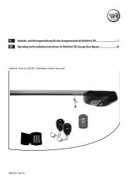
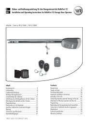
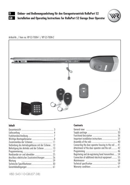
DGBEinbau- <strong>und</strong> <strong>Bedienungsanleitung</strong> <strong>für</strong> <strong>den</strong> <strong>Garagentorantrieb</strong> RolloPort S2Installation and Operating Instructions for RolloPort S2 Garage Door OperatorArtikel-Nr. / Item no: RP-S2-700N-1 / RP-S2-700N-2InhaltGesamtansicht ........................................................ 3Lieferumfang ........................................................ 4Funktionsbeschreibung ............................................ 7Wichtige Montagehinweise ..................................... 8Zusammenbau der Schienen .................................. 11Verbindung des Antriebsgehäuses mit der Schiene .. 12Befestigung des Antriebs <strong>und</strong> der Schiene .............. 13Programmierung ................................................... 17Handsender an- <strong>und</strong> abmel<strong>den</strong> .............................. 25Anschluss elektrischer Zusatzeinrichtungen ............. 26Wartung ...................................................... 29Technische Spezifikationen .................................... 30Garantiebedingungen ............................................ 61ContentsGeneral view ........................................................ 3Supply package .................................................... 33Functional description ........................................... 36Important installation instructions .......................... 37Assembly of the rails ............................................ 40Connecting the door operator housing to the rail .... 41Attachment of the door operator and the rail .......... 42Programming ...................................................... 46Registering and de-registering hand transmitters ..... 54Connection of additional electrical equipment ......... 55Maintenance ...................................................... 58Technical specification ........................................... 59Warranty conditions .............................................. 61VBD 543-1-D-GB-(07.08)
iSehr geehrte K<strong>und</strong>en...D...mit dem Kauf dieses <strong>Garagentorantrieb</strong>s habenSie sich <strong>für</strong> ein Qualitätsprodukt aus dem Hause <strong>Rademacher</strong>entschie<strong>den</strong>. Wir danken Ihnen <strong>für</strong> Ihr Vertrauen.Der <strong>Rademacher</strong> <strong>Garagentorantrieb</strong>ist unterAspekten des größten Komfortsentstan<strong>den</strong>. Mit einemkompromisslosenQualitätsanspruch <strong>und</strong>nach langen Versuchsreihensind wir stolz, Ihnendieses innovative Produktzu präsentieren.Dahinter stehen alle hochqualifiziertenMitarbeiterinnen<strong>und</strong> Mitarbeiter ausdem Hause RADEMACHER.CE-Zeichen <strong>und</strong> KonformitätDas vorliegende Produkt erfüllt die Anforderungender gelten<strong>den</strong> europäischen <strong>und</strong> nationalen Richtlinien.Die Konformität wurde nachgewiesen, die entsprechen<strong>den</strong>Erklärungen <strong>und</strong> Unterlagen sind beim Herstellerhinterlegt.iDiese Anleitung...iZeichenerklärung...beschreibt Ihnen die Montage, <strong>den</strong>elektrischen Anschluss <strong>und</strong> die Bedienungdes RolloPort S2.Lebensgefahr durch StromschlagDieses Zeichen weist Sie auf Gefahren bei Arbeiten anelektrischen Anschlüssen, Bauteilen etc. hin. Es fordertSicherheitsmaßnahmen zum Schutz von Ges<strong>und</strong>heit <strong>und</strong>Leben der betroffenen Person.Bitte lesen Sie diese Anleitung vollständig durch <strong>und</strong>beachten Sie alle Sicherheitshinweise, bevor Sie mit<strong>den</strong> Arbeiten beginnen.Bitte bewahren Sie diese Anleitung auf <strong>und</strong> übergebenSie die Anleitung bei einem Besitzerwechsel auch demNachbesitzer.Bei Schä<strong>den</strong>, die durch Nichtbeachtung dieser Anleitung<strong>und</strong> der Sicherheitshinweise entstehen, erlischt die Garantie.Für Folgeschä<strong>den</strong>, die daraus resultieren, übernehmenwir keine Haftung.STOPHier geht es um Ihre Sicherheit.Beachten <strong>und</strong> befolgen Sie bitte alle so gekennzeichnetenHinweise.So warnen wir vor Fehlverhalten, das zu Personen-oder Sachschä<strong>den</strong> führen kann.HINWEIS/WICHTIG/ACHTUNGAuf diese Weise machen wir Sie auf weitere, <strong>für</strong> dieeinwandfreie Funktion, wichtige Inhalte aufmerksam.2
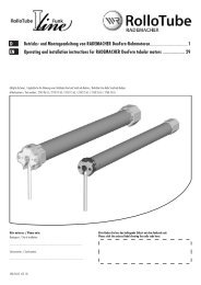
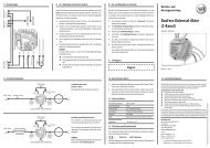
iGesamtansicht / General ViewDGB31DLegende1 = Antrieb, inkl. Beleuchtung2 = Handsender3 = LED4 = 1. Taste des Handsenders5 = 2. Taste des Handsenders6 = Set-Taste (S)7 = Anzeige8 = Einstellungstaste (+)9 = Einstellungstaste (-)10 = Programmiertaste (P)6 7 8542GBKey1 = Operator, including lighting2 = Hand transmitter3 = LED4 = 1st hand transmitter button5 = 2nd hand transmitter button6 = Set button (S)7 = Display8 = Button for adjustment (+)9 = Button for adjustment (-)10 = Programming button (P)10 93
Warranty conditions .............................................. 61Technical specification ........................................... 5958...................................................... MaintenanceConnection of additional electrical equipment ......... 5554 ..... transmitters hand de-registering and Registering543-1-D-GB-(07.08)VBD............................................ 61GarantiebedingungenSpezifikationen .................................... 30Technische...................................................... 29Wartungelektrischer Zusatzeinrichtungen ............. 26Anschlussan- <strong>und</strong> abmel<strong>den</strong> .............................. 25Handsender................................................... 17Programmierungdes Befestigung Antriebs <strong>und</strong> der Schiene .............. 1312 .. Schiene der mit Antriebsgehäuses des Verbindung11.................................. Schienen der Zusammenbau8..................................... Montagehinweise Wichtige7............................................ Funktionsbeschreibung4........................................................ Lieferumfang3........................................................ GesamtansichtInhaltProgramming ...................................................... 46operator and the rail .......... 42door the of AttachmentConnecting the door operator housing to the rail .... 4140............................................ rails the of AssemblyImportant installation instructions .......................... 3736........................................... description FunctionalSupply package .................................................... 333........................................................ view GeneralContentsArtikel-Nr. / Item no: RP-S2-700N-1 / RP-S2-700N-2GB Installation and Operating Instructions for RolloPort S2 Garage Door OperatorS2 RolloPort <strong>Garagentorantrieb</strong> <strong>den</strong> <strong>für</strong> <strong>Bedienungsanleitung</strong> <strong>und</strong> Einbau- DiLieferumfangD1.10.Vegleichen Sie nach dem Auspacken <strong>den</strong>Packungsinhalt mit <strong>den</strong> Angaben zumLieferumfang:2.3.4.5.11.12.13.14.15.1.2.3.4.5.6.7.8.9.10.11.12.13.14.15.16.17.1 x Antrieb1 x <strong>Bedienungsanleitung</strong>2 x Handsender FR321 x Handsender FR11; inkl. Wandhalter1 x Toranbinder, gebogen2 x Mittenabhängung3 x Haltewinkel1 x Sturzwinkel1 x Torwinkel1 x Vielzahnverbinder8 x Sechskant-Blechschraube (6 x 15 mm)1 x Schraube (6 x 80 mm) mit Sechskantmutter1 x Bolzen (8 x 20 mm)1 x Sicherungssplint (2 x 20 mm)4 x Schraube (8 x 20 mm ) mit Sechskantmutter<strong>und</strong> Unterlegescheibe6 x Dübel (10 mm)6 x Sechskantschraube (8 x 60 mm)1 x Schlagdorn6.16.18.19.20.2 x Montagelochband3 x Schienen + 2 x Verbinder1 x Codierschaltgerät mit Funk FA627.17.8.18.9.19. 20.4
iRichtige VerwendungDVerwen<strong>den</strong> Sie <strong>den</strong> <strong>Garagentorantrieb</strong> ausschließlich:◆ zum Öffnen <strong>und</strong> Schließen von Garagentoren◆ im privaten Bereich◆ gemäß <strong>den</strong> Angaben <strong>und</strong> Sicherheitsbestimmungenin dieser AnleitungEine andere Verwendung gilt als nicht bestimmungsgemäß.Richtige Verwendung des HandsendersDie Fernsteuerung per Handsender ist nur <strong>für</strong> Geräte<strong>und</strong> Anlagen zulässig, bei <strong>den</strong>en eine Funkstörung imSender oder Empfänger keine Gefahr <strong>für</strong> Menschen, Tiereoder Gegenstände ergibt oder das Risiko durch andereSicherheitseinrichtungen abgedeckt wird.Halten Sie alle Wartungsintervalle einZur richtigen Verwendung gehört auch die regelmäßigeKontrolle des Tores <strong>und</strong> seiner Sicherheitseinrichtungen.iEinsatzbedingungeni◆ Betreiben Sie <strong>den</strong> <strong>Garagentorantrieb</strong> nur in trockenenRäumen.◆ Das Garagentor muss sich leicht von Hand öffnen<strong>und</strong> schließen lassen, es darf nicht klemmen.Falsche Verwendung◆ Achten Sie darauf dass die Deckenlaufschienen immerfett- <strong>und</strong> schmutzfrei sind. Verschmutzte Deckenlaufschienenbehindern <strong>den</strong> einwandfreien Betrieb.◆ Am Einbauort muss eine 230 V/50 Hz Steckdosevorhan<strong>den</strong> sein.Durch unsachgemäße bauliche Veränderungenbesteht Verletzungsgefahr.Nehmen Sie keine baulichen Veränderungen am Antrieb,dem Garagentor oder eventuell vorhan<strong>den</strong>en Sicherheitseinrichtungenvor, die von <strong>den</strong> in dieser Anleitung beschriebenenMaßnahmen abweichen. Solche Veränderungengefähr<strong>den</strong> die Betriebssicherheit.Der <strong>Garagentorantrieb</strong> darf nichteingesetzt wer<strong>den</strong>:◆ in gewerblichen Betrieben◆ zum Antrieb anderer Gegenstände◆ im DauerbetriebDurch eine falsche Montage besteht VerletzungsgefahrBewegliche Teile des Garagentores dürfen niein öffentliche Fuß- oder Radwege hineinragen.Für Schä<strong>den</strong> die durch eine falsche bzw. nicht bestimmungs-gemäßeVerwendung entstehen, haftet der Herstellernicht (s. Garantiebestimmungen).iZulässige Garagentorarten◆◆ausschwingende Standard-SchwingtoreSektionaltoreDie Tore müssen leichtgängig sein <strong>und</strong> <strong>den</strong> Anforderungenfolgender Normen entsprechen: EN 12453 <strong>und</strong> EN12604SchwingtoreDeckensektionaltore5
iUnzulässige GaragentorartenDTore, die Kipp- <strong>und</strong> Drehbewegungen erfordern,dürfen nicht mit dem <strong>Garagentorantrieb</strong>S2 betrieben wer<strong>den</strong>.Nicht ausschwingendesKipptoriAllgemeine SicherheitshinweiseBei Arbeiten an elektrischen Anlagen bestehtLebensgefahr durch Stromschlag.◆ Lassen Sie alle Arbeiten an elektrischen Anlagen <strong>und</strong>am Antrieb nur von einer zugelassenen Elektrofachkraftdurchführen.◆ Vor allen Arbeiten am Tor oder Torantrieb immer <strong>den</strong>Netzstecker aus der Steckdose ziehen.Der Einsatz defekter Geräte kann zur Gefährdungvon Personen <strong>und</strong> zu Sachschä<strong>den</strong> führen.◆ Verwen<strong>den</strong> Sie niemals defekte oder beschädigteGeräte.◆ Prüfen Sie Antrieb <strong>und</strong> das Netzkabel aufUnversehrtheit.◆ Wen<strong>den</strong> Sie sich bitte an unseren K<strong>und</strong>endienst(s. Seite 62), falls Sie Schä<strong>den</strong> am Gerät feststellen.Defekte Tore können zu Verletzungen führen◆ Der Lauf des Tores darf nicht durch schlecht eingestellteFedern oder durch schlecht funktionierendeToraufhängungen bzw. Torkonstruktionen beeinträchtigtwer<strong>den</strong>.◆ Es besteht Verletzungsgefahr durch die sehr starkgespannten Torfedern. Tauschen Sie niemals selbstdie Torfedern aus.◆ Lassen Sie alle Arbeiten an der Tormechanik <strong>und</strong><strong>den</strong> Federn von einer Fachkraft durchführen.Durch unsachgemäßen Gebrauch besteht erhöhteVerletzungsgefahr.◆ Greifen Sie nie in das fahrende Tor oder in bewegteTeile.◆ Unterweisen Sie alle Personen, die das Garagentorbedienen, im sicheren Gebrauch.◆ Erlauben Sie niemandem, unter dem sich bewegen<strong>den</strong>Tor durchzulaufen.◆ Halten Sie Kinder vom sich bewegen<strong>den</strong> Tor fern.◆ Verbieten Sie Kindern, mit dem Tor oder dem Handsenderzu spielen.◆ Bewahren Sie <strong>den</strong> Handsender so auf, dass ein ungewollterBetrieb z. B. durch spielende Kinderausgeschlossen ist.◆ Fahren Sie nur in bzw. aus der Garage, wenn dasTor vollständig geöffnet ist <strong>und</strong> still steht.Bei fehlerhaften oder nicht funktionieren<strong>den</strong>Sicherheitseinrichtungen besteht Verletzungsgefahroder Sachbeschädigungen könnendie Folge sein.◆ Überprüfen Sie vor der ersten Inbetriebnahme <strong>und</strong>einmal monatlich die korrekte Funktion der Sicherheitseinrichtungen(z.B. der Kraftbegrenzung).◆ Setzen Sie niemals die Sicherheitseinrichtungenaußer Kraft.◆ Halten Sie <strong>den</strong> Toranschlag am Bo<strong>den</strong> von Eis,Schnee, Schmutz <strong>und</strong> Steinen frei.Bei kraftbetätigten Toren besteht Quetsch<strong>und</strong>Schergefahr an <strong>den</strong> Schließkanten.◆ Achten Sie darauf, dass sich während des Betriebeskeine Personen im Schwenkbereich des Garagentoresaufhalten.6
iFunktionsbeschreibungDIntelligenter MikrocomputerIntelligente, computergesteuerte, exakte Hubpositionierung,zeitnahe Kraftermittlung, Rücklauf beimAuftreffen auf Hindernisse.AntriebGeringer Lärm, Softstart <strong>und</strong> Softstop schützen <strong>den</strong> Antrieb<strong>und</strong> gewährleisten eine lange Lebensdauer.SelbstdiagnoseBetriebsmodus <strong>und</strong> digitales Menü wer<strong>den</strong> im Displayangezeigt, Selbstdiagnose (L-Normal, F-Unterbrochen,H-Lesefehler, A-Infrarotstrahl unterbrochen).CryptoguardRollierende Code-Technologie bietet Milliar<strong>den</strong> von Code-Kombinationen <strong>und</strong> macht je<strong>den</strong> Handsender einzigartig,um vor unbefugtem Zugang zu schützen.AlarmeinheitDer Alarm ertönt, wenn das Tor länger als 10 Minutenoffen gelassen wird. Der Alarm endet, wenn das Torwieder geschlossen wird (siehe Seite 22 „Alarmeinstellung“).NotentriegelungDas Tor kann im Falle eines Stromausfalls durch Ziehenam Seil der Notentriegelung von Hand betrieben wer<strong>den</strong>.Automatische SchließfunktionDie automatische Schließzeit des Tores kann von 30bis 240 Sek<strong>und</strong>en eingestellt wer<strong>den</strong> (siehe Seite 22/23).2000-Zyklen-AlarmWenn der Antrieb 2000 Zyklen durchlaufen hat, ertöntein Signalton, um <strong>den</strong> Anwender daran zu erinnern,das mechanische System zu warten (siehe Seite 19).BeleuchtungDer <strong>Garagentorantrieb</strong> S2 verfügt über eine interne Beleuchtungdie nach jedem Schaltimpuls eingeschaltetwird <strong>und</strong> automatisch nach 3 Minuten wieder ausgeht.Zusätzliche Anschlussmöglichkeiten <strong>für</strong>externes Zubehör <strong>und</strong> SicherheitseinheitZusätzlich können Sie einen externen Schalter, sowieeine Infrarot-Lichtschranke anschließen (s. Seite 26).iFunktionsbeschreibung/HinderniserkennungDer Antrieb besitzt eine automatische Hinderniserkennung(durch interne Kraftüberwachung).Stößt das Tor bei Schließen oder Öffnen gegen ein Hindernis,stoppt der Antrieb automatisch <strong>und</strong> fährt in dieGegenrichtung bis zum jeweiligen Endpunkt.Nach der Beseitigung des Hindernisses können Sie <strong>den</strong><strong>Garagentorantrieb</strong> wieder normal bedienen.7
iFunktionsbeschreibung/NotentriegelungDDas Tor kann im Falle eines Stromausfalls durch Ziehenam Seil der Notentriegelung von Hand bedient wer<strong>den</strong>.Es besteht Verletzungsgefahr. Das Tor kannbeim Entriegeln unkontrolliert herunterfallen(z.B. wenn das Tor sich nicht im Gleichgewichtbefindet)◆ Schließen oder öffnen Sie nach jeder Entriegelungdas Tor immer vollständig.◆ Die Notentriegelung ist nicht <strong>für</strong> <strong>den</strong> “täglichenGebrauch” bestimmt.Wichtige MontagehinweisePrüfen Sie vor der Montage ...:◆ ...ob Ihr Antrieb <strong>für</strong> <strong>den</strong> Garagentortyp <strong>und</strong> dieGaragentorhöhe geeignet ist.◆ ...das Tor auf seinen einwandfreien mechanischenZustand. Das Tor muss leichtgängig sein <strong>und</strong> sichim Gleichgewicht befin<strong>den</strong>. Überprüfen Sie, ob essich ordnungsgemäß öffnet <strong>und</strong> schließt;Öffnen Sie das Tor ca. 1 m <strong>und</strong> lassen Sie es dannlos, ein ausgewogenes Tor sollte jetzt in dieser Stellungstehen bleiben. Wenn nicht lassen Sie Ihr Tordurch einen Fachbetrieb einstellen.◆ Der Lauf des Tores darf nicht durch schlecht eingestellteFedern oder durch schlecht funktionierendeToraufhängungen bzw. Torkonstruktionen beeinträchtigtwer<strong>den</strong>.STOPWährend der Montage besteht Verletzungsgefahrdurch Herabstürzen des ungesichertenTores.◆ Achten Sie bei der Montage darauf, dass sich keinePersonen im Schwenkbereich des Garagentores aufhalten.Falsche Montage kann zu schweren Unfällen<strong>und</strong> zu Verletzungen führen.◆ Beachten <strong>und</strong> befolgen Sie alle Montagehinweise.◆ Installieren Sie die Betätigung <strong>für</strong> die Notentriegelungin einer Höhe von weniger als 1,8 m.◆ Verwen<strong>den</strong> Sie ausschließlich das beigefügte Montagematerialsowie nur Original-Ersatzteile <strong>und</strong> Original-Zubehör.◆ Bauseitig vorhan<strong>den</strong>e Torverriegelungen können <strong>den</strong>korrekten Lauf des Tores behindern <strong>und</strong> müssen deshalbdemontiert wer<strong>den</strong>.◆ Mangelnde Beleuchtung behindert die Montage <strong>und</strong>kann zu Verletzungen führen. Sorgen Sie <strong>für</strong> ausreichendeBeleuchtung während der Montage.◆ Es kann vorkommen, dass Sie während der Montagedas Tor <strong>für</strong> eine Weile nicht mehr öffnen können.8
Notwendige WerkzeugeDSie benötigen folgende WerkzeugeEntfernen der Torverriegelungen1.Demontieren Sie alle senkrechten <strong>und</strong>waagerechten Torverriegelungen.WICHTIG!Heben Sie die „alten“ Torverriegelungengut auf.Falls Sie <strong>den</strong> <strong>Garagentorantrieb</strong> einmal demontieren,müssen Sie diese wieder montieren um <strong>den</strong> Originalzustanddes Tores wieder herzustellen.9
Maß nehmenD1.Tormitte ausmessen <strong>und</strong> markierenMarkieren Sie die Tormitte wie gezeigt an der Toroberkante,am Torsturz <strong>und</strong> an der Garagendecke.2.Abstand zwischen Toroberkante <strong>und</strong>Decke ermittelnSchließen Sie das Tor langsam <strong>und</strong> messen Sie <strong>den</strong> Abstandzwischen Toroberkante <strong>und</strong> Decke.Schwingtormin. 6 cmHINWEISDer Mindestabstand sollte 6 cm betragen.Sektionaltormin. 6 cm3.Montagehinweis zum Einbau anSektionaltorenWird der <strong>Garagentorantrieb</strong> <strong>für</strong> ein Sektionaltor verwendet,so muss bei geschlossenem Tor die Führungsrolle des oberstenTorsegments im Bogen der Führungsschiene stehen.✗RichtigFalsch10
Zusammenbau der SchienenDHINWEISDer RolloPort S2 wird mit drei Schienen geliefert:◆ zwei Endstücke, inkl. vormontierter Kette◆ ein Mittelteil (ohne Kette) mit zwei Verbindern1231.2.3.4.5.Legen Sie die bei<strong>den</strong> Endstücke mit dervormontierten Kette so auf <strong>den</strong> Bo<strong>den</strong>,dass die Kette möglichst gerade zwischenIhnen verläuft.Schieben Sie die bei<strong>den</strong> beiliegen<strong>den</strong> Verbinderüber das Mittelteil <strong>und</strong> legen Sieanschließend das Mittelteil in die Lückezwischen <strong>den</strong> bei<strong>den</strong> EndstückenFühren Sie die Kette in das Mittelteil ein.Schieben Sie je<strong>den</strong> der Verbinder über dieSchnittstelle zwischen Mittelteil <strong>und</strong> dementsprechen<strong>den</strong> Endstück.Achten Sie darauf, dass die Verbinder jeweils mittig zwischen<strong>den</strong> Fixierungsblechen der Schienenunterseite liegen.Biegen Sie zum Schluss die Fixierungsblechemit einem kleinen Schraubendrehernach außen.Dadurch lassen sich die Verbinder nicht mehr verschieben.Verbinder 1FixierungsblecheVerbinder 2Antriebskette spannen1.2.Schrauben Sie die Spannmutter mit einemgeeigneten Steckschlüssel (∅ 10 mm)fest.Justieren Sie die Kettenspannung, wie imBild dargestellt.1.2.11
Verbindung des Antriebsgehäuses mit der SchieneD1.2.3.Setzen Sie zuerst <strong>den</strong> Vielzahnverbinder(5) ein.Setzen Sie die Schiene (4) mit dem innenliegen<strong>den</strong>Kettenritzel (ab Werk in derSchiene vormontiert) über <strong>den</strong> Verbinder(5).Stecken Sie zwei Haltewinkel (2) auf dieSchiene (4) <strong>und</strong> schrauben Sie diese mit<strong>den</strong> beiliegen<strong>den</strong> Sechskant-Blechschrauben(6 x 15 mm) am Antriebsgehäuse fest.WICHTIGAchten Sie darauf, das der Mikroschalter (3) bei derMontage der Schiene nicht beschädigt wird.14235Legende1 = Sechskant Blechschrauben (6 x 15 mm)2 = Haltewinkel3 = Mikroschalter4 = Schiene5 = Vielzahnverbinder12
Befestigung des Antriebs <strong>und</strong> der SchieneD(A)(D)(C)(B)A / B / C / D, siehe folgende SeitenSturzmontageDie Montage sollte vorzugsweise am Sturz erfolgen,da so die auftreten<strong>den</strong> Kräfte optimal aufgenommenwer<strong>den</strong> können.min. 1,5 cmDeckenmontageFür die Deckenmontage sollten Sie <strong>den</strong> Sturzwinkelum 90 Grad drehen <strong>und</strong> weiter innen an derGaragendecke befestigen. Dadurch kann der gesamteSchienenweg genutzt wer<strong>den</strong>.HINWEISDer Abstand zum Torblatt darf bei einer Deckenmontagemax. 25 cm betragen.WICHTIGVerwen<strong>den</strong> Sie bei Garagenwän<strong>den</strong> bzw. Garagendeckenaus Stein (Beton), die beiliegen<strong>den</strong> Sechskantschrauben(8 x 60) <strong>und</strong> Dübel ∅ 10 mm.SturzmontageDeckenmontagemax. 25 cm13
(A) Montage des Sturzwinkels (1)DHINWEISDer Sturzwinkel (1) muss mittig zum Tor montiert wer<strong>den</strong>.213 41.2.3.Zeichnen Sie die Position des Sturzwinkels(1) an <strong>und</strong> bohren Sie die Montagelöcher(z.B. mit einem 10 mm Steinbohrer).Schrauben Sie <strong>den</strong> Sturzwinkel (1) mit <strong>den</strong>beiliegen<strong>den</strong> Sechskantschrauben (8 x 60mm) fest.Befestigen Sie danach die Schiene (4) mitder beiliegen<strong>den</strong> Sechskantschraube (6 x80 mm) am Sturzwinkel (1).Legende1 = Sturzwinkel2 = Schraube (6 x 80 mm) mitSechskantmutter3 = Sechskantschraube (8 x 60 mm)4 = Schiene(B) Montage des Haltewinkels (5) am Antriebskopf (7)1.Schieben Sie <strong>den</strong> Haltewinkel (5) möglichstnah vor <strong>den</strong> Antriebskopf (7) aufdie Schiene (4).452.Markieren Sie die Montagelöcher <strong>für</strong> <strong>den</strong>Haltewinkel (5).Dazu sollten Sie die gesamte Konstruktion hochheben<strong>und</strong> gegen die Decke drücken.HINWEISAchten Sie darauf dass die Schiene (4) in Flucht zurTormitte liegt.673.4.Bohren Sie die Montagelöcher (z.B. miteinem 10 mm Steinbohrer).Schrauben Sie zum Schluss <strong>den</strong> Haltewinkel(5) mit <strong>den</strong> beiliegen<strong>den</strong> Sechskantschrauben(8 x 60 mm) an der Garagendeckefest.Legende4 = Schiene5 = Haltewinkel6 = Sechskantschraube (8 x 60 mm)7 = Antriebskopf14
(C) Montage des Torwinkels (8)DHINWEISWir empfehlen Ihnen <strong>den</strong> Torwinkel (8) vorzugsweiseam Torrahmen zu befestigen.Für Kunststoff- oder dünnwandige Holztore sind zusätzlicheVerstrebungen nötig, um eine Beschädigung desTores zu vermei<strong>den</strong>. Sprechen Sie in diesem Fall mitIhrem Torlieferanten.Verwen<strong>den</strong> Sie zur Montage des Torwinkels (8)schon vorhan<strong>den</strong>e Bohrlöcher, falls möglich.89101112Legende8 = Torwinkel9 = Bolzen (8 x 20 mm)10 = Sechskant-Blechschraube (6 x 15 mm)11 = Sicherungssplint (2 x 20 mm)12 = Toranbinder, gekrümmt1.Legen Sie <strong>den</strong> Torwinkel (8) auf die Oberkantedes Garagentores <strong>und</strong> richten Sieihn zur Tormitte (in Flucht zum Profilschlitten)aus. Zeichnen Sie anschließenddie vier Befestigungslöcher auf dem Torrahmenan.2.Schlagen Sie die Befestigungslöcher mitHilfe des beiliegen<strong>den</strong> Schlagdorns in <strong>den</strong>Torrahmen.RICHTIGFALSCHHINWEISBlechschrauben benötigen ausreichend Halt im Material.Prüfen Sie die Materialstärke Ihres Torrahmens.Bei ausreichender Materialstärke können Sie die Befestigungslöcherauch mit einem 4 mm Metallbohrer vorbohren,falls Sie die Löcher nicht mit dem Schlagdorneinschlagen können.Befestigungslochdurch SchlagdornBefestigungslochdurch BohrungDie Schraube hatausreichend HaltDie Schraube hatkeinen Halt15
(C) Montage des Torwinkels (8)D3.4.5.Schrauben Sie <strong>den</strong> Torwinkel (8) mit <strong>den</strong>beiliegen<strong>den</strong> Sechskant-Blechschrauben(8 x 15 mm) am Rahmen fest.Befestigen Sie zum Schluß <strong>den</strong> Toranbinder(12) mit dem beiliegen<strong>den</strong> Bolzen (9) amTorwinkel (8).HINWEISAb Werk ist schon ein gerader Toranbinder vormontiert,dieser ist fest mit der Schiene verb<strong>und</strong>en.Falls Sie (je nach örtlichen Gegebenheiten) <strong>den</strong> beiliegen<strong>den</strong>,gebogenen Toranbinder (12) verwen<strong>den</strong> wollen,müssen Sie diesen mit zwei Sechskantschrauben(8 x 20 mm) am gera<strong>den</strong> Toranbinder befestigen.Sichern Sie zum Schluss <strong>den</strong> Bolzen (9)durch Aufstecken des Sicherungssplints(11) gegen Herausrutschen.9(D) Montage der Mittenabhängung (13)1.Die Mittenabhängung (13) an geeigneterStelle, möglichst mittig zwischen Tor <strong>und</strong>Antriebskopf, montieren.13Legende13 = Mittenabhängung14 = Sechskantschrauben (8 x 60 mm)1416
Hinweisschilder mit Warnhinweisen anbringenDDurch unsachgemäßen Gebrauch bestehterhöhte Verletzungsgefahr.◆ Bringen Sie vor der Inbetriebnahme die beiliegen<strong>den</strong>Hinweisschilder/Aufkleber an geeigneten StellenIhres Garagentores <strong>und</strong> am Profilschlitten an.◆ Bringen Sie alle Schilder so an, dass Sie gut lesbarsind.Betriebsbereitschaft des Tores herstellen1.2.3.Bewegen Sie das Tor vorsichtig, um <strong>den</strong>Schlitten einzurasten.Stecken Sie <strong>den</strong> Netzstecker in die Steckdose<strong>und</strong> schalten Sie <strong>den</strong> Strom ein.Das Licht geht an <strong>und</strong> die Einheit gibt eineneinmaligen Signalton von sich <strong>und</strong> dasDisplay zeigt zyklisch ‘0’ an.ProgrammierungDamit die folgen<strong>den</strong> Einstellungen korrekt gespeichert<strong>und</strong> ausgeführt wer<strong>den</strong>, müssen Sieeine abschließende Programmierung gemäßSeite 24 durchführen.17
Endpunkte einstellen / Oberen Endpunkt einstellenDDie falsche Reihenfolge bei der Einstellungder Endpunkte führt zu Fehlfunktionen. HaltenSie unbedingt die vorgegebene Einstellreihenfolgeein.Korrekte Einstellreihenfolge:1. oberen Endpunkt einstellen2. unteren Endpunkt einstellen1. Drücken Sie „P“ <strong>für</strong>ca. 5 Sek<strong>und</strong>en.2. Der Antrieb erzeugteinen Signalton <strong>und</strong>zeigt „1“.3. Drücken Sie „P“,„1“ blinkt.4. Drücken Sie „+“ oderdrücken Sie „-“ .Unteren Endpunkt einstellen5. Das Tor fährt auf oderzu.6. Ist das Tor bis zur gewünschtenPosition hochgefahren,drücken Sie „P“, um<strong>den</strong> oberen Endpunkt zuspeichern.1. Drücken Sie „+“, in derAnzeige erscheint „2“.2. Drücken Sie „P“,„2“ blinkt.3. Drücken Sie „+“ oderdrücken Sie „-“.4. Das Tor fährt auf oderzu.5. Ist das Tor bis zur gewünschten Positionheruntergefahren, drücken Sie „P“, um<strong>den</strong> unteren Endpunkt zu speichern.18
Referenzfahrt zur Kraftmessung durchführenDWährend der Referenzfahrt besteht Verletzungsgefahr,da der Antrieb sehr großeKräfte entwickelt.1. Drücken Sie „+“, in derAnzeige erscheint „3“.2. Drücken Sie „P“,„3“ blinkt.3. Das Tor hebt sich automatisch.4. Drücken Sie nach demStopp 2 x auf „P“.5. Das Tor senkt sich. 6. Drücken Sie nach dem Stopp„P“, um die Information zuspeichern.7. Programmierungabschließen,(s. Seite 24, Methode 1).WICHTIGMit der Einstellung der bei<strong>den</strong> Endpunkte <strong>und</strong> mit der Referenzfahrt zur Kraftmessunghaben Sie die erforderlichen Gr<strong>und</strong>einstellungen zum sicheren Betrieb erfüllt.Falls Sie keinen Bedarf an weiteren Einstellungen haben, müssen Sie die Programmierunggemäß Methode 1 auf der Seite 24 abschließen um die vorangegangenenGr<strong>und</strong>einstellungen zu übernehmen.Die folgen<strong>den</strong> individuellen Einstellungen können Sie danach jeweils einzeln odernach allen Einstellungen mit der Methode 2 auf Seite 24 abschließen.19
Kraftbegrenzung bei Bedarf anpassenDHINWEISDer Antrieb ist ab Werk auf Stufe 3 eingestellt. Bei Bedarf(z.B. bei zu niedrigem Kraftniveau) können Siedie Kraftbegrenzung nachträglich anpassen.Ein zu niedriges Kraftniveau beeinträchtigtdie Torbewegung, besonders wenn die mechanischeStruktur des Tores nicht gut ausbalanciertist.1. Drücken Sie auf „+“(evtl. mehrfach drücken)bis die „4“ angezeigtwird.niedrig2. Drücken Sie „P“, in derAnzeige erscheint „7 “(Stufe 3).Kraftniveau3. Drücken Sie „+“ oderdrücken Sie „-“, um dieStufe auszuwählen.hochWerkseinstellung4. Drücken Sie „P“, um dieEinstellung zu speichern.5. WICHTIGReferenzfahrt zur Kraftmessungwiederholen,(s. Seite 19).6. Programmierungabschließen,(s. Seite 24, Methode 1).Nach einer Neueinstellung des Kraftniveaus müssen Sie zwingend die Referenzfahrt zur Kraftmessungwiederholen <strong>und</strong> erneut die Programmierung abschließen.Während der Referenzfahrt besteht Verletzungsgefahr, da der Antrieb sehr große Kräfte entwickelt.20
Bedientaste des Handsenders einstellenDHINWEISDie Steuerung des Tores ist ab Werk auf die erste Tastedes Handsenders eingestellt. „0“ bedeutet, dass keineTaste ausgewählt ist.1. Drücken Sie auf „+“(evtl. mehrfach drücken)bis die „5“ angezeigtwird.2. Drücken Sie „P“,„2“ blinkt.(2 = Werkseinstellung )3. Drücken Sie „+“ oder „-“,um <strong>den</strong> gewünschten Kanalauszuwählen.1 = Taste 12 = Taste 24. Drücken Sie Taste „P“um die Einstellung zuspeichern.5. Programmierungabschließen(s. Seite 24, Methode 2)oder weiter mit nächsterEinstellung.21
AlarmeinstellungDWenn der Alarm eingeschaltet ist erzeugt derAntrieb einen Signalton, wenn das Tor längerals 10 Minuten geöffnet ist. Der Signaltonertönt alle 10 Minuten <strong>für</strong> 30 Sek<strong>und</strong>en.Been<strong>den</strong> des Alarmtons:Drücken Sie die Torsteuerungstaste, um das Tor vollständigzu schließen.1. Drücken Sie auf „+“(evtl. mehrfach drücken)bis die „6“ angezeigtwird.2. Drücken Sie „P“, dieAnzeige ist „0“.(0 = Aus = Werkseinstellung)3. Drücken Sie „+“, dieAnzeige ist „1“.(1 = Ein = Die Alarmeinstellung isteingeschaltet)4. Drücken Sie „P“ um dieAlarmeinstellung zuspeichern.5. Programmierungabschließen(s. Seite 24, Methode 2)oder weiter mit nächsterEinstellung.Automatische SchließzeiteinstellungHINWEISBevor sich das Tor automatisch schließt, erzeugt der Antrieb<strong>für</strong> 20 Sek<strong>und</strong>en einen Signalton. Gleichzeitig blinktdas Licht.Sobald sich das Tor schließt, bleibt das Licht dauerhafteingeschaltet <strong>und</strong> der Signalton ertönt weiter.Nachdem das Tor geschlossen ist beendet der Antrieb<strong>den</strong> Signalton <strong>und</strong> das Licht bleibt <strong>für</strong> weitere 3 Minutenan.1. Drücken Sie auf „+“(evtl. mehrfach drücken)bis die „7“ angezeigtwird.2. Drücken Sie „P“, dieAnzeige ist „0“.(0 = Aus = Werkseinstellung)3. Drücken Sie „+“, dieAnzeige ist „1“.(1 = Ein = Automatische Schließzeit= 30 Sek<strong>und</strong>en)22
Automatische SchließzeiteinstellungD4. Drücken Sie „+“ <strong>und</strong>wählen Sie diegewünschte Schließzeit:1 = 30 s2 = 60 s3 = 90 s4 = 120 s5 = 150 s6 = 180 s7 = 210 s8 = 240 s(Maximum)5. Drücken Sie „P“ um dieEinstellung zu speichern.6. Programmierungabschließen,(s. Seite 24,Methode 2)oder weitermit nächster Einstellung.2000-Zyklen-AlarmeinstellungÜberprüfen Sie nach einiger Zeit des Betriebesregelmäßig, ob das Tor beim Öffnen/Schließen horizontal ist <strong>und</strong> ob die Feder genügendKraft hat, um das Tor zu heben.Fügen Sie zu allen beweglichen Teilen regelmäßigeine geeignete Menge Schmiermittelhinzu.HINWEISIst diese Funktion aktiviert, wird der Antrieb nach 2000Zyklen in gewissen Abstän<strong>den</strong> durch einen kurzen Pfeiftonsignalisieren, dass das Tor gewartet wer<strong>den</strong> muss.Alarmton been<strong>den</strong>Schalten Sie <strong>den</strong> Strom aus <strong>und</strong> wieder ein, oder drückenSie die Taste „P“ <strong>für</strong> 5 Sek<strong>und</strong>en.1. Drücken Sie auf „+“(evtl. mehrfach drücken)bis die „8“ angezeigtwird.2. Drücken Sie „P“, dieAnzeige ist „0“.(0 = Aus = Werkseinstellung)3. Drücken Sie „+“, dieAnzeige ist „1“.(1 = Ein)4. Drücken Sie „P“, um dieEinstellung zu speichern.5. Programmierung abschließen (s. Seite 24, Methode 2)oder weiter mit nächster Einstellung.23
Programmierung abschließenDWICHTIGBitte beachten, dieser abschließende Schritt muss ausgeführtwer<strong>den</strong>, da die gespeicherten Informationenansonsten verloren gehen.HINWEISSie können die Programmierung wie folgt auf 2 Artenabschließen:Methode 1: Diese Methode unbedingt nach der Referenzfahrt durchführen1. Drücken Sie nach derReferenzfahrt auf „-“(evtl. mehrfach drücken)bis „1“ angezeigt wird.2. Halten Sie „P“5 Sek<strong>und</strong>en langgedrückt.3. „0“ wird zyklisch angezeigt,um die Programmierungabzuschließen <strong>und</strong> <strong>den</strong>Antrieb in <strong>den</strong> Ruhezustandzu versetzen.Methode 2: Nach allen anderen Einstellungen1. Halten Sie nach Abschlusseiner beliebigen Einstellung„P“ 5 Sek<strong>und</strong>en langgedrückt.2. „0“ wird zyklisch angezeigt,um die Programmierungabzuschließen <strong>und</strong><strong>den</strong> Antrieb in <strong>den</strong> Ruhezustandzu versetzen.24
Handsender an- <strong>und</strong> abmel<strong>den</strong>DHandsender anmel<strong>den</strong>:1. Drücken Sie „S“ <strong>für</strong>1 Sek<strong>und</strong>e <strong>und</strong> lassenSie los.2. Zur Quittierung erscheintkurz ein grüner Punktrechts unten in der Anzeige.3. Drücken Sie dreimal aufdie zuvor eingestellteTaste des Handsenders.HINWEISNach erfolgreicher Anmeldung können Sie Ihren <strong>Garagentorantrieb</strong> mit dem Handsender bedienen. Danach können Sie weitereHandsender anmel<strong>den</strong>.Handsender abmel<strong>den</strong>:Aus Sicherheitsgrün<strong>den</strong> muss ein Handsenderbei Verlust abgemeldet wer<strong>den</strong>, damit dasGaragentor nicht durch Unbefugte bedientwer<strong>den</strong> kann.1. „S“ drücken <strong>und</strong>gedrückt halten.2. Zur Quittierung erscheintein grüner Punkt rechtsunten in der Anzeige.3. Halten Sie „S“ solangegedrückt, bis der grünePunkt unten rechts in derAnzeige erlischt.Alle Handsender sind abgemeldet.Sie können einen neuen Handsenderanmel<strong>den</strong>.25
Anschluss elektrischer ZusatzeinrichtungenDBei allen Arbeiten an elektrischen Anlagenbesteht Lebensgefahr durch Stromschlag.◆ Der Anschluss von elektrischen Zusatzeinrichtungendarf nur durch eine zugelassene Elektrofachkraft erfolgen.◆ Ziehen Sie vor dem Öffnen der Abdeckhaube immer<strong>den</strong> Netzstecker <strong>und</strong> prüfen Sie die Anlage auf Spannungsfreiheit.Herstellerfremdes Zubehör kann zu Fehlfunktionenoder zu Sachbeschädigungen führen.◆ Verwen<strong>den</strong> Sie ausschließlich Original-Zubehör.Fremdspannung an <strong>den</strong> Schraubklemmen <strong>für</strong> <strong>den</strong>externen Taster führt zum Kurzschluss <strong>und</strong> zurZerstörung der Antriebselektronik.◆ Keine Fremdspannung an die Klemme <strong>für</strong> <strong>den</strong> externenTaster anschließen die Klemmen sind potentialfreieKontakte.Die unsachgemäße Montage von externenTastern kann die Betriebssicherheit gefähr<strong>den</strong>.Montieren Sie Innentaster, Codierschalter etc. immer:◆ außerhalb der Reichweite von sich bewegen<strong>den</strong>Teilen.◆ in Sichtweite des Tores◆ mindestens in 1,5 m Höhe213Legende1 = Hauptplatine2 = Infrarot-Lichtschranke (optional)3 = externer Schalter (optional)Anschlussbedingungen zum Anschluss einerInfrarot-Lichtschranke:Spannung: = 12 - 24 VStrom: = 150 mATyp: = NO/NC26
Manueller Betrieb des ToresD1.Im Falle eines Stromausfalls:Wollen Sie das Tor bei Stromausfall manuellbedienen, müssen Sie am Seil derNotentriegelung ziehen, damit diese dasTor vom Antrieb entriegelt.Danach können Sie das Tor frei bewegen.Es besteht Verletzungsgefahr. Das Tor kannbeim Entriegeln unkontrolliert herunterfallen(z.B. wenn das Tor sich nicht im Gleichgewichtbefindet)◆ Schließen oder öffnen Sie nach jeder Entriegelungdas Tor immer vollständig.◆ Die Notentriegelung ist nicht <strong>für</strong> <strong>den</strong> “täglichenGebrauch” bestimmt.Wenn der Strom wieder da ist:1. Bedienen Sie <strong>den</strong> Handsender oder <strong>den</strong>HINWEISWandschalter.Das Einkuppeln erfolgt automatisch.27
Anleitung <strong>für</strong> <strong>den</strong> AnwenderDHinweise <strong>für</strong> <strong>den</strong> Einsatz◆ Überprüfen Sie das Antriebssystem um festzustellen,ob es sich beim ersten Einsatz des <strong>Garagentorantrieb</strong>sleicht bewegt.◆ Überprüfen Sie nach einiger Zeit im Gebrauchregelmäßig, ob das Tor beim Öffnen/Schließen horizontalbleibt <strong>und</strong> ob die Feder genügend Kraft hat,um das Tor zu heben. Fügen Sie zu allen beweglichenTeilen regelmäßig eine geeignete MengeSchmiermittel hinzu.◆ Im Falle eines Stromausfalls können Sie dieNotentriegelung ziehen <strong>und</strong> das Tor von Hand freibewegen.Wenn der Strom wieder zur Verfügung steht, könnenSie <strong>den</strong> Handsender oder die Wandkonsole bedienen,die Notentriegelung rastet automatisch ein.Das Tor kann danach wieder mit dem Handsenderoder der Wandkonsole bedient wer<strong>den</strong>.1. Im Falle eines Stromausfallsstoppt das Torseine Bewegung.2. Drücken Sie sobald derStrom wieder zur Verfügungsteht, die zuvoreingestellte Taste (s.Seite 21) des Handsenders,das Tor öffnetsich.3. Entsprechend dem Programmspeicherhebt sichdas Tor bis zum oberenEndpunkt <strong>und</strong> bleibt dannstehen.Normalbetrieb◆ FernbedienungDurch das Drücken der zuvor eingestellten Taste desHandsenders kann das Tor geöffnet, geschlossen oderangehalten wer<strong>den</strong>.◆ HandbedienungIm Falle eines Stromausfalls kann das Öffnen oderSchließen des Tors von Hand erfolgen, sobald derAntrieb entkoppelt wurde (s. Seite 27).28
WartungDDurch defekte Toranlagen bzw. Sicherheitseinrichtungenbesteht Verletzungsgefahr.Zu Ihrer Sicherheit sollten Sie die empfohlenenWartungsintervalle <strong>für</strong> Ihre Toranlageinkl. aller Sicherheitseinrichtungen einhalten.Wartungsintervall:Lassen Sie die Toranlage vor der ersten Inbetriebnahme,je nach Bedarf jedoch mindestenseinmal jährlich von einem Fachbetriebprüfen.Prüfen Sie:◆ Alle Schraubenverbindungen auf festen Sitz◆ Kabel auf Beschädigung◆ Federn <strong>und</strong> BefestigungsteileEs besteht Verletzungsgefahr durch diesehr stark gespannten Torfedern.◆ Tauschen Sie niemals selbst die Torfedern aus.◆ Lassen Sie alle Arbeiten an der Tormechanik <strong>und</strong><strong>den</strong> Federn von einem Fachmann durchführen.Regelmäßige Prüfungen der VerschleißteileEs besteht Verletzungsgefahr durch defektebzw. verschlissene Bauteile.Prüfen Sie daher die Anlage regelmäßig auf Anzeichenvon Verschleiß, Beschädigung oder auf mangelhafteBalance des Tores.Benutzen Sie das Tor auf keinen Fall, wenn ReparaturoderEinstellarbeiten durchgeführt wer<strong>den</strong> müssen.Monatliche Prüfung der Hinderniserkennung (Kraftbegrenzung)1.2.3.4.5.6.Fahren Sie das Tor in die Endstellung auf.Legen Sie einen 50 mm hohen Gegenstand,z. B. einen Holzklotz, in die Laufrichtungdes Tores.Schließen Sie das Tor durch Betätigendes Handsenders.Stößt das Tor bei Schließen oder Öffnengegen ein Hindernis, stoppt der Antriebautomatisch <strong>und</strong> öffnet das Garagentorvollständig.Entfernen Sie anschließend das Hindernis.Nach der Beseitigung des Hindernisseskönnen Sie <strong>den</strong> <strong>Garagentorantrieb</strong> wiedernormal bedienen.Einen ca. 50 mm Holzklotz in die Laufrichtung desTores legen.29
iTechnische SpezifikationenDModell <strong>und</strong> empfohlene VerwendungArtikel-Nr. Spannung (V) Torgröße (m 2 ) Zulässige Umgebungstemperatur (°C)RP-S2-700N-1RP-S2-700N-2220 – 240 ≤ 10 –20...+40Führungsschiene <strong>und</strong> verfügbare GrößenArtikel-Nr. Gesamtlänge Bewegungshub HubhöheRP-S2-700N-1 3020 mm 2560 mm < 2240 mmRP-S2-700N-2 3620 mm 3160 mm < 2840 mmTechnische DatenLeistung:100 WStandby-Modus:< 1 WZugkraft:700 NVersorgungsspannung: 230 V / 50 HzMotor:24 V (DC) GleichstromLicht :Power LED mit ZeitbegrenzungTorlaufgeschwindigkeit: 11 cm/Sek<strong>und</strong>eSicherungsmodell:- Antriebssicherung 1: 2,5 A- Lichtsicherung 2: 2,5 ASenderfrequenz <strong>und</strong> -reichweite: 433 MHz/offenes Gelände 50 mAntrieb:KetteSchutzmethode:Nur in trocken Räumen verwen<strong>den</strong>Zulässige GaragentormaßeZulässige Torblattfläche:Max. Füllungsgewicht<strong>für</strong> Schwingtore: 7 kg/m 210,5 m 2 (<strong>für</strong> leichtgängige Schwing- <strong>und</strong> Sektionaltore)30
iFehlerbehebungDFehlerDer Antrieb funktioniert nicht.Der Handsender kann <strong>den</strong> Antriebnicht bedienen.Die Reichweite des Handsenders ist zugering.Die Kette bewegt sich, aber das Tornicht.Im Betrieb ist ein reibendes Geräuschzu hören.Die Kette hängt durch <strong>und</strong> ist laut.Das Tor bewegt sich nicht <strong>und</strong> aufdem Display wird nichts angezeigt.Die rote LED-Leuchte auf derLeiterplatte ist an.Ursachen1. Der Stecker ist nicht sicher eingesteckt.2. Die Sicherung hat ausgelöst.1. Der Handsender wurde eventuellfalsch oder gar nicht angemeldet2. Die Batterie ist leer.Die Batterie ist möglicherweise leer.Die Notentriegelung ist möglicherweiseausgelöst.Mangel an Schmiermittel zwischenSchiene <strong>und</strong> Kettenschlitten nach langerBedienzeit.Die Kette ist lose aufgr<strong>und</strong> langen Gebrauchsohne Schmiermittel zwischender Schiene <strong>und</strong> dem Kettenschlitten.Das Torsystem ist nicht gut ausbalanciert<strong>und</strong> verursacht eine hohe Spitzenleistung.Hierdurch wird die Schutzfunktiondes Antriebs ausgelöst.Lösung1. Netzstecker in Steckdose stecken.2. Ursache von einem Technikerprüfen lassen, danach die Sicherungwieder einschalten.1. Mel<strong>den</strong> Sie <strong>den</strong> Handsender neuan, siehe Seite 25.2. Setzen Sie eine neue Batterie ein.Ersetzen Sie sie durch eine Neue vomgleichen Modell.Bedienen Sie <strong>den</strong> Antrieb, bis dieNotentriegelung automatisch wiedereinrastet.Fügen Sie an der Position zwischenSchiene <strong>und</strong> Kettenschlitten ein geeignetesSchmiermittel ein.Spannen Sie die Kette wie auf Seite11beschrieben <strong>und</strong> tragen Sie eingeeignetes Schmiermittel auf die Ketteauf.Schalten Sie die Stromversorgung <strong>für</strong>mindestens 3 Minuten ab. Justieren Siedann das Torsystem <strong>und</strong> stellen Sie sicher,dass es gut ausbalanciert ist.31
iDear Customers...GB...with your purchase of this garage door operator,you have decided for a quality product manufacturedby <strong>Rademacher</strong>. We would like to thank you for yourconfi<strong>den</strong>ce.The new <strong>Rademacher</strong>garage door operatorhas been designed in aneffort to the graetest possibleease of operation.With uncompromisingquality requirements, afterextensive test series, weare proud to present this innovativeproduct to you.All of our highly qualifiedstaff at RADEMACHERstand behind this product.CE Mark and ConformityThis present product complies with the requirementsof the applicable european and national directives.The conformity has been proved and the correspondingdeclarations and documentation are available on file atthe manufacturer’s premises.iThese instructions...iKey to Symbols…describe how to install, connectand operate the RolloPort S2.Danger of fatal electric shockThis sign warns of danger when working on electricalconnections, components etc. It requires that safetyprecautions be taken to protect the health and life ofthe person concerned.Before you begin work, please read these instructionsall the way through and follow all of the safetyinstructions.Please save these instructions and give them to anyfuture owners.For damage resulting from noncompliance with theseinstructions and safety instruc-tions, the guarantee isvoid. We assume no liability for any consequent damage.STOPThis concerns your safetyPlease pay particular attention to and carefully followall instructions with this symbol.This symbol advises of malpractices that cancause damage to people and property.NOTE/IMPORTANT/CAUTIONThis is to draw your attention to information which worksis important to ensure trouble-free operation.32
Warranty conditions .............................................. 61Technical specification ........................................... 5958...................................................... MaintenanceConnection of additional electrical equipment ......... 5554 ..... transmitters hand de-registering and Registering543-1-D-GB-(07.08)VBD............................................ 61GarantiebedingungenSpezifikationen .................................... 30Technische...................................................... 29Wartungelektrischer Zusatzeinrichtungen ............. 26Anschlussan- <strong>und</strong> abmel<strong>den</strong> .............................. 25Handsender................................................... 17Programmierungdes Befestigung Antriebs <strong>und</strong> der Schiene .............. 1312 .. Schiene der mit Antriebsgehäuses des Verbindung11.................................. Schienen der Zusammenbau8..................................... Montagehinweise Wichtige7............................................ Funktionsbeschreibung4........................................................ Lieferumfang3........................................................ GesamtansichtInhaltProgramming ...................................................... 46operator and the rail .......... 42door the of AttachmentConnecting the door operator housing to the rail .... 4140............................................ rails the of AssemblyImportant installation instructions .......................... 3736........................................... description FunctionalSupply package .................................................... 333........................................................ view GeneralContentsArtikel-Nr. / Item no: RP-S2-700N-1 / RP-S2-700N-2GB Installation and Operating Instructions for RolloPort S2 Garage Door OperatorS2 RolloPort <strong>Garagentorantrieb</strong> <strong>den</strong> <strong>für</strong> <strong>Bedienungsanleitung</strong> <strong>und</strong> Einbau- DiSupply packageGB1.10.Please compare the contents of thepackage with the content description onthe packaging:2.3.4.5.11.12.13.14.15.1.2.3.4.5.6.7.8.9.10.11.12.13.14.15.16.17.1 x Drive1 x Operating instructions2 x Hand transmitter FR321 x Hand transmitter FR11, incl. wall support1 x Door connector, bent2 x Middle support clip3 x Fixing bracket1 x Header bracket1 x Door bracket1 x Connector8 x Self-tapping hexagon screw (6 x 15 mm)1 x Screw (6 x 80 mm) with hexagon nut1 x Bolt (8 x 20 mm)1 x Securing bolt (2 x 20 mm)4 x Screw (8 x 20 mm) with hexagon nutand plain washer6 x Wall plug (10 mm)6 x Hexagon head screw (8 x 60 mm)1 x Spike6.16.18.19.20.2 x Mounting strap3 x Rails + 2 x Connectors1 x Keypad FA627.17.8.18.9.19. 20.33
iCorrect useGBUse the garage door operator only:◆ to open and close garage doors◆ for private use◆ according to the instructions and safetyregulations in this manualAny other use shall be regarded as non-compliantwith the intended use.Correct use of the hand transmitterThe remote control via hand transmitter is onlyadmissible for appliances and equipment in which radiointerference in the transmitter or receiver does notpresent a hazard for persons, animals or property or forwhich the risk is covered by other safety equipment.Comply with all maintenance intervalsProper use also includes the regular inspection of thedoor and its safety equipment.iOperating conditionsi◆ Only operate the garage door operator in dry rooms.◆ The garage door must be able to be opened andclosed easily by hand and must not jam.Improper use◆ Ensure that the overhead ceiling tracks are alwaysfree of grease and dirt. Dirty overhead ceiling trackshinder proper operation.◆ A 230 V/50 Hz power supply must be available atthe place of installation.Incorrectly performed structural alterationsresult in the risk of injury.Do not carry out any structural alterations to the dooroperator, the garage door or any existing safetyequipment which deviate from the measures describedin this manual. Such alterations endanger the operatingsafety.The garage door operator must not be used:◆ in commercial establishments◆ to operate other objects◆ in continuous operationIncorrect installation results in the risk ofinjury.Movable parts of the garage door must not extend intopublic footpaths or cycle paths.The manufacturer is not liable for damage which occursdue to incorrect or non-compliant use (see warrantyconditions).iAdmissible garage door types◆ swing out standard up-and-over doors◆ sectional doorsThe doors must move smoothly and comply with theregu-lations of the following standards: EN 12453 andEN 12604.34Up-and-over doorsCeiling sectional doors
iInadmissible types of garage doorGBDoors which require tilting and rotatingmovements may not be operated with thetype S2 garage door operator.Non swinging outretractable up-andoverdooriGeneral safety instructionsAll work performed on electrical equipmentis associated with a risk of electric shock andelectrocution.◆ Have all work on electrical equipment and on thedoor operator carried out by a qualified electrician.◆ Before commencing any work on the door or thedoor operator, unplug the mains cable from theelectrical socket.The use of defective devices can put peopleand property at risk.◆ Never use faulty or damaged devices.◆ Please make sure that the door operator and mainscable are free from damage.◆ Please notify our customer service department (seepage 62) of any faults or damage to the device.Faulty doors can result in injuries.◆ The operation of the door must not be hindered bybadly adjusted springs or poorly functioning doorinstallation or door constructions.◆ There is a risk of injury due to the tightly stretcheddoor springs. Never replace the door springs yourself.◆ Have all work on the door mechanics and the springscarried out by a qualified person.Power-driven doors entail the risk ofcrushing and shearing at the closing edge.◆ Ensure that during operation there are no personsin the swivelling range of the garage door.Improper use increases the risk of injury.◆ Never reach into the moving door or into movingparts.◆ Instruct all persons who operate the garage door inthe safe use of the equipment.◆ Do not allow anyone to go through <strong>und</strong>er the movingdoor.◆ Keep children away when the door is moving.◆ Do not allow children to play with the door or withthe hand transmitter.◆ Please store the hand transmitter in such a way thatit cannot unintentionally be operated by, e.g. playingchildren.◆ Drive in and out of the garage only when the dooris fully open and stationary.In the case of defective or inoperable safetyequipment there is a danger of injury ordamage to property.◆ Before first operation and thereafter one a monthinspect the correct functioning of the safetyequipment (e.g. the power limiter).◆ Never switch off the safety equipment.◆ Keep the door limit stop on the gro<strong>und</strong> free of ice,snow, dirt and stones.35
iFunctional descriptionGBIntelligent microcomputerIntelligent, computerized, exact positioning of travel,prompt power determination, reverses if obstructionsare met.Door operatorLow noise, soft start and soft stop protect the motorand ensure a long service life.Self diagnosisOperational mode and digital menu shown on thedisplay, self diagnosis.(L-Normal, F-Interrupted, H-FailIn Reading, A-Infrared Ray Interrupted)CryptoguardRolling code technology provides billions of codecombinations and makes every remote control a uniqueone that protects against unauthorized access.Alarm unitThe alarm so<strong>und</strong>s when the door is left open for longerthan 10 minutes. The alarm stops when the door isclosed again (refer to „Alarm setting“ on page 51).Emergency release deviceThe door can be manually operated by pulling down onthe emergency release cable in the case of power failure.Automatic closing function AutomatischeSchließfunktionThe automatic closing time of the door can be set from30 to 240 seconds (refer to page 51/52).2000 cycle alarm2000-Zyklen-AlarmWhen the operator has run 2000 cycles, it will beep toremind the user to service the mechanical system (referto page 52).LightingThe S2 garage door operator has internal lighting whichis switched on after each switching impulse and goesoff again automatically after 3 minutes.Additional connecting options for externalaccessories and safety unitIn addition you can connect an external switch and aninfrared photoelectric barrier (refer to page 55).iFunctional description / Recognition of obstructionsThe door operator has an automatic obstacle-recognitionsystem (through internal monitoring of power).If the door encounters an obstruction when closing oropening, the door operator stops the door automaticallyand moves it in the opposite direction until it reachesthe corresponding limit.After removing the obstruction you can operate thegarage door operator normally again.36
iFunctional description/emergency releaseGBIn the event of a power cut, the door can be operatedmanually by pulling the emergency release cable.There is a risk of injury. The door can fall uncontrollablywhen it is released (e.g. if thedoor is not balanced).◆ Always close or open the door fully after each release.◆ The emergency release is not intended for„everyday use“.Important installation instructionsBefore installation check...:◆ ...whether your door operator is suitable for the typeof garage door and the garage door height.◆ ...that the door is in a perfect mechanical state. Thedoor must be smooth running and be balanced.Check whether it opens and closes properly;Open the door approx. 1 metre and let go. Abalanced door should now remain in this position.If not, have your door adjusted by a specialistcompany.◆ The door operation must not be hindered by incorrectlyadjusted springs or by incorrectly functioningdoor suspensions or door constructions.STOPDuring installation there is a danger of injurydue to the unsecured door falling sud<strong>den</strong>ly.◆ During the installation work, ensure that there areno persons in the swivelling area of the garage door.Faulty installation can result in seriousacci<strong>den</strong>ts and injuries.◆ Observe and comply with all installation instructions.◆ Fit the actuator for the emergency release at a heightof less than 1.8 metres.◆ Use only the enclosed mounting materials and onlyoriginal spare parts and original accessories.◆ Any existing door locking devices already fitted tothe door may hinder the correct functioning of thedoor and must therefore be removed.◆ Poor lighting hinders the installation work and canresult in injuries. Ensure that there is adequatelighting during installation work.◆ It is possible that during the installation work, youmay not be able to open the door for a short periodof time.37
Required toolsGBYou require the following toolsRemove the door locks1.Remove all vertical and horizontal doorlocks and catches.IMPORTANT!Keep the „old“ door locks in asafe place.In the event that you should remove the garage dooroperator, you will have to fit these again in order torestore the original state of the door.38
Take measurementsGB1.Measure up and mark the centre of thedoorMark the centre of the door, as shown, on the upperedge of the door, on the door lintel and on the garageceiling.2.Determine the distance between the topedge of the door and the ceilingClose the door slowly and measure the distance betweenthe top edge of the door and the ceiling.up-and-downdoormin. 6 cmNOTEThe minimum distance should be 6 cm.sectionaldoormin. 6 cm3.Installation advice for fitting tosectional doorsIf the garage door operator is used for a sectional door,then the guide roller of the upper door segment mustbe in the bend of the guide rail when the door is closed.✗RightWrong39
Assembly of the railsGBNOTEThe RolloPort S2 is supplied with three rails:◆ two end pieces, including a pre-assembled chain◆ a middle piece (without a chain) with two connectors1231.2.3.4.5.Lay the two end pieces with the preassembledchain on the gro<strong>und</strong>, with thechain lying as straight as possible betweenthe two end pieces.Push the two enclosed connectors onto themiddle piece and then lay the middle piecein the gap between the two end pieces.Insert the chain into the middle piece.Push each of the connectors onto the joinbetween the middle piece and each of theend pieces.Please ensure that each of the connectors lies in thecentre between the fixing plates of the rail <strong>und</strong>erside.Finally, bend the fixing plates outwardswith a small screwdriver.As a result, the connectors can no longer be moved.Connector 1Fixing platesConnector 2Tension the drive chain1.2.Screw the clamping nut tight with asuitable socket key (∅ 10 mm).Adjust the tension of the chain as shownin the picture.1.2.40
Connect the door operator housing to the railGB1.2.3.First of all insert the connector (5).Place the rail (4) with the inboard chainsprocket (supplied pre-assembled in therail) over the connector (5).Place the two fixing brackets (2) over therail (4) and screw these firmly onto thedoor operator housing with the enclosedself-tapping hexagon screws (6 x 15 mm).IMPORTANTEnsure that the microswitch (3) is not damagedwhen mounting the rail.14235Key1 = Self-tapping hexagon screw (6 x 15 mm)2 = Fixing brackets3 = Microswitch4 = Rail5 = Connector41
Attachment of the door operator and the railGB(A)(D)(C)(B)A / B / C / D refer to the following pagesInstallation on the lintelThe installation should preferably be on the lintel, asthis means that the forces encountered can best beabsorbed.Installation on the ceilingFor installation on the ceiling, you should rotate theheader bracket by 90 degrees and fix it to the ceilingfurther inward. The full rail length can then be used asa result.NOTEWhen fitted to the ceiling, the distance to the door leafmust be a maximum of 25 cm.IMPORTANTIn the case of garage walls or garage ceilings made ofstone (concrete), use the enclosed hexagon screws(8 x 60) and wall plugs ∅ 10 mm.Installationon thelintelInstallationon theceilingmin. 1,5 cmmax. 25 cm42
(A) Installation of the header bracket (1)GBNOTEThe header bracket (1) must be aligned with the midpointof the door.213 41.2.3.Mark out the position of the header bracket(1) and drill the mounting holes (e.g.with a 10 mm masonry drill bit).Screw the header bracket (1) tight withthe enclosed hexagon screws (8 x 60 mm).Then fix the rail (4) with the enclosedhexagon screw (6 x 80 mm) to the headerbracket (1).Key1 = Header bracket2 = Screw (6 x 80 mm) with hexagon nut3 = Hexagon screw (8 x 60 mm)4 = Rail(B) Installation of the fixing bracket (5) at the door operator head (7)1.Push the fixing bracket (5) onto the rail(4), as close to the door operator head(7) as possible.452.Mark the mounting holes for the fixingbracket (5).In order to do so, lift the entire construction and pushit against the ceiling.NOTEEnsure that the rail (4) is aligned with the centre ofthe door.673.4.Drill the mounting holes (e.g. with a 10mm masonry drill bit).Finally screw the fixing bracket (5) to thegarage ceiling with the enclosed hexagonscrews (8 x 60 mm).Key4 = Rail5 = Fixing bracket6 = Hexagon screw (8 x 60 mm)7 = Door operator head43
(C) Installation of the door bracket (8)GBNOTEWe recommend fixing the door bracket (8) to the doorframe if possible.For plastic or thin-walled woo<strong>den</strong> doors, additional crossbeamsare necessary in order to avoid damaging thedoor. In this case, consult your door supplier.Use existing drillholes, if possible, to mount the doorbracket (8).89101112Key8 = Door bracket9 = Bolt (8 x 20 mm)10 = Self-tapping hexagon screw (6 x 15 mm)11 = Securing bolt (2 x 20 mm)12 = Door connector, bent1.Place the door bracket (8) on the top edgeof the garage door and align it with thecentre of the door (in a line with theprofile slide). Next, mark out the fourfixing holes on the door frame.2.Punch in the fixing holes in the door framewith the aid of the enclosed spikeRIGHTWRONGNOTESelf-tapping screws need sufficient hold in the material.Check the thickness of your door frame. If it issufficiently thick you can also pre-drill the fixing holeswith a 4 mm metal drill bit if you are not able to punchin the holes with the spike.Fixing hole madeusing spikeFixing hole madeby drillingThe screw hassufficient holdThe screw does nothave sufficient hold44
(C) Installation of the door bracket (8)GB3.4.5.Screw the door bracket (8) tight with theenclosed self-tapping hexagon screws(8 x 15 mm).Finally, fix the door connector (12) to thedoor bracket (8) with the enclosed bolt(9).NOTEA straight door connector is supplied pre-assembled, andthis is permanently fixed to the rail.If you wish to use the bent door connector (12)enclosed (depending upon your door particularconfiguration), you must attach this with two hexagonscrews (8 x 20) to the straight door connector.Finally, secure the bolt (9) by attachingthe securing bolt (11) to prevent it fromslipping out.9(B) Installation of the middle support clip (13)1.Fit the middle support (13) clip at asuitable place, as near as possible to themiddle point between the door and thedoor operator head.Key13 = Middle support clip14 = Hexagon screws (8 x 60 mm)131445
Attach safety notices with warning messagesGBImproper use results in an increased risk ofinjury.◆ Before initial operation, attach the enclosed safetynotices to suitable places on your garage door and onthe profile slide.◆ Attach all notices so that they are clearly legible.Establish operational readiness of the door1.2.3.Move the door carefully, in order toengage the profile slide.Plug the mains plug into the socket andswitch on the electricity.The light goes on and the unit gives asingle beep and the display shows ‘0’ atregular intervals.ProgrammingIn order that the following settings arecorrectly stored and executed, you must carryout a final programming procedure accordingto page 53.46
Setting limits / setting the upper limitGBCarrying out the instructions in the wrongorder when setting the limits will result inmalfunctions. Be sure to keep to the settingorder specified.Correct setting order:1. Set upper limit2. Set lower limit1. Press „P“ forapprox. 5 seconds.2. The door operatorbeeps and shows „1“.3. Press „P“,„1“ flashes.4. Press „+“ or press „-“.5. The door opensor closes.6. If the door has moved upwardsto the required position,press „P“ to storethe upper limit.Setting the lower limit1. Press „+“, thedisplay shows „2“.2. Press „P“,„2“ flashes.3. Press „+“ or press „-“.4. The door opensor closes.5. If the door has moved downwardsto the required position, press „P“to store the lower limit.47
Carry out reference run for power measurementGBDuring the reference run there is a risk ofinjury, as the door operator developsextremely strong forces.1. Press „+“, thedisplay shows „3“.2. Press „P“,„3“ flashes.3. The door goes upautomatically.4. After it has stopped,press the „P“ buttontwice.5. The door goes down. 6. After it has stopped, press„P“, to store the information.7. Conclude the programming(refer topage 53, method 1).IMPORTANTOnce you have set the two limits and the reference run for power measurement,you have fulfilled the basic settings required for safe operation.If you do not require any further settings, you must conclude programming asspecified in method 1 on page 53, in order to adopt the basic settings you havejust programmed. -After this, you can conclude the following individual settings, either singly or afterall the settings have been programmed, using method 2 on page 53.48
Adjust power limiting as requiredGBNOTEThe door operator is preset to stage 3 by the supplier. Ifrequired (e.g. if the power level is too low) you cansubsequently adjust the power limiting setting.If the power level is too low, the doormovement will be impaired, particularly if themechanical structure of the door is not wellbalanced.1. Press „+“ (if necessarypress several times) until„4“ is displayed.2. Press „P“, the displayshows „7“ (stage 3).3. Press „+“ or press „-“to select the stage.LowPower levelHighFactory setting4. Press „P“, in orderto store the setting.5. IMPORTANTRepeat reference runfor power limiting(refer to page 48).6. Conclude programming(refer to page 53,method 1).After a resetting of the power level, it is absolutely necessary to repeat the reference run for powerlimiting and to conclude the programming again.During the reference run there is a risk of injury as the door operator develops extremely strongforces.49
Set control button of hand transmitterGBNOTEThe actuation of the door is preset by the supplier tocorrespond to the first button of the hand transmitter.„0“ means that no button has been selected.1. Press „+“ (if necessarypress several times) until„5“ is displayed.2. Press „P“,„2“ flashes.(2 = factory setting)3. Press „+“ or „-“ to selectthe required channel.1 = button 12 = button 24. Press button „P“ inorder to store thesetting.5. Conclude programming(refer to page 53, method 2)orproceed to next setting.50
Alarm settingGBIf the alarm is switched on, the door operatorbeeps if the door is open for longer than 10minutes. The door operator beeps for 30seconds every 10 minutes.To end the beeping:Press the door control button to fully close the door.1. Press „+“ (press severaltimes if necessary) until„6“ is displayed.2. Press „P“,the display is „0“.(0 = off = factory setting)3. Press „+“,the display is „1“ .(1 = on = the alarm setting isswitched on)4. Press „P“ in order tostore the alarm setting.5. Conclude programming(refer to page 53, method 2)orproceed with next setting.Automatic closing time settingNOTEBefore the door closes automatically, the door operatorbeeps for 20 seconds. At the same time the light flashes.When the door starts closing, the light shines durably and itbeeps permanently.After the door has closed, the door operator ends thebeeping and the light remains on for a further 3 minutes.1. Press „+“ (press severaltimes if necessary) until„7“ is displayed.2. Press „P“,the display is „0“.(0 = off = factory setting)3. Press „+“,the display is „1“.(1 = on = automatic closingtime = 30 seconds)51
Automatic closing time settingGB4. Press „+“ and selectthe required closing time:1 = 30 sec. 5 = 150 sec.2 = 60 sec. 6 = 180 sec.3 = 90 sec. 7 = 210 sec.4 = 120 sec. 8 = 240 sec.(maximum)5. Press „P“ in orderto store the setting.6. Conclude programming(refer to page 53,method 2)orproceed with the nextsetting.2000 cycle alarm settingAfter a period of time in use, regularly checkto see whether the door is level whenopening/closing, and whether the spring hasenough force to raise the door.Add a suitable amount of lubricant to allmoving parts regularly.NOTEIf this function is activated, after 2000 cycles the dooroperator will indicate with a short whistling tone atregular intervals that door maintenance must be carriedout.To end the alarm toneSwitch the power supply off and then on again, or pressthe „P“ button for the door for 5 seconds.1. Press „+“ (press severaltimes if necessary) until„8“ is displayed.2. Press „P“,the display is „0“.(0 = off = factory setting)3. Press „+“,the display is „1“.(1 = on)524. Press „P“ in orderto store the setting.5. Conclude programming (refer to page 53, method 2) orproceed with next setting.
Conclude programmingGBIMPORTANTPlease note: this concluding step must be carried out,otherwise the information stored will be lost.NOTEYou can conclude the programming in two ways:Method 1: Carry out this method without fail after the reference run.1. After the reference run,press „-“ (press severaltimes if necessary) until„1“ is displayed.2. Keep „P“ pressedfor 5 seconds.3. „0“ will be displayed atregular intervals in order toconclude the programmingand set the door operatorinto an idle state.Method 2: After all other settings1. After completing anysetting, press „P“for 5 seconds.2. „0“ will be displayed atregular intervals in orderto conclude the programmingand set the door operatorinto an idle state.53
Registering and de-registering hand transmittersGBRegistering hand transmitters:1. Press „S“ for 1second and thenlet go.2. As acknowledgement, agreen point will appearfor a short time at thebottom right of thedisplay.3. Press the previously setbutton on the handtransmitter three times.NOTEAfter successfully registering you can operate your garage door operator with the hand transmitter. After that you can alsoregister further hand transmitters.De-registering hand transmitters:For security reasons, a hand transmitter mustbe de-registered in the event of loss, toprevent the garage door from being operatedby unauthorised persons.1. Press „S“ andkeep pressed.2. As acknowledgement, agreen point will appearfor a short time on thebottom right of thedisplay.3. Keep „S“ pressed until thegreen point at the bottomright of the display disappears.All hand transmitters are de-registered.You can register a new hand transmitter.54
iConnecting additional electrical equipmentGBWhen working on electrical systems there isa risk of danger to life due to electrocution.◆ The connection of additional electrical equipmentmust only be carried out by a qualified electrician.◆ Before opening the protective cover always disconnectthe equipment from the mains power supplyand check that the system is free of voltage.Accessories from other manufacturers mayresult in malfunctions or damage to property.◆ Use only original accessories. A separate sourcevoltage at the screw-type terminal for the externalswitch will result in a short circuit and will destroythe door operator’s electronics.◆ Do not connect any separate source voltages to theterminal for the external switch. The terminals arepotential-free contacts.If the external buttons are not connectedproperly, the operational safety of theequipment is at risk.Always mount the internal button, programming button,etc.:◆ outside the reach of movable parts◆ within visibility of the door◆ at a height of at least 1.5 metres213Key1 = Motherboard2 = Infrared-photocell barrier (optional)3 = External switch (optional)Connecting conditions for connecting aninfrared photocell barrier:Voltage: = 12 - 24 VCurent: = 150 mAType: = NO/NC55
iManual door operationGBIn the case of power failure:1.If you wish to manually operate the doorin the event of a power cut, you must pullthe emergency release cable so that thisreleases the door from the door operator.After that you can move the door freely.There is a risk of injury. The door can falldown uncontrollably when released (e.g. ifthe door is not balanced)◆ Close or open the door fully after each release.◆ The emergency release is not intended for„everyday use“.If power recovers:1. Operate the hand transmitter or theNOTEwall switch.Engagement happens automatically.56
iInstructions for the userGBNotes for use◆ Check the operator system to determine whether itmoves smoothly the first time the garage door operatoris used.◆ After some time in use, check regularly to see whetherthe door remains horizontal when opening and closingand whether the spring has enough power to lift thedoor. Lubricate all movable parts regularly with a suitablelubricant.◆ In the event of a power cut, you can pull the emergencyrelease and freely move the door manually.When the power is back, you can operate the handtransmitter or the wall panel, and the emergency releasewill engage automatically.The door can then be operated again with the handtransmitter or the wall panel.1. In the event of a powercut, the door stopsmoving.2. Once the power is back on,press the previously setbutton (refer to page 50)on the hand transmitter,and the door will open.3. According to the programmemory, the door will openas far as the upper limitand then stop.Normal operation◆ Remote controlBy pressing the previously set button on the handtransmitter, the door can be opened, closed or stopped.◆ Manual operationIn the event of a power cut, the door can be opened orclosed manually as soon as the door operator has beendisengaged (refer to page 56).57
MaintenanceGBDefective door systems and safety equipmentresult in the risk of injury.For your safety, you should comply with therecommended maintenance intervals for yourdoor system, including all safety equipment.Maintenance interval:Have the door system inspected by a specialistcompany before initial operation and thenas required, but at least once a year.Regular checks of wearing parts:There is a risk of injury due to defectiveor worn components.Check:◆ All screw connections to ensure they are tight◆ Cables for damage◆ Springs and fixing partsThere is a risk of injury due to the extremelytaut door springs.◆ Never replace the door springs yourself.◆ Have all work on the mechanical system and springscarried out by a qualified person.Check the system therefore regularly for signsof wear, damage or lack of balance of the door.Do not use the door <strong>und</strong>er any circumstances if repairsor adjustments need to be made.Monthly checks on the obstacle recognition (power limiting)1.2.3.4.5.6.Run the door into the final open position.Place a 50 mm high object, e.g. a woo<strong>den</strong>block, in the direction of travel of thedoor.Close the door by actuating the handtransmitter.If the door hits an obstruction whenclosing or opening, the door operatorautomatically stops and opens the garagedoor fully.After this, remove the obstruction.After removing the obstruction, you canoperate the garage door operator normallyagain.Placing an approx. 50 mm woo<strong>den</strong> block in the directionof travel of the door.58
iTechnical SpecificationGBModel and recommended useItem no. Voltage (V) Door size (m 2 ) Admissible ambient temperature (°C)RP-S2-700N-1RP-S2-700N-2220 – 240 ≤ 10 –20...+40Guide rail and available sizesItem no. Total lenght Height of travel Lifting heightRP-S2-700N-1 3020 mm 2560 mm < 2240 mmRP-S2-700N-2 3620 mm 3160 mm < 2840 mmTechnical DataOutput:100 WStandby mode:< 1 WTractive force:700 NSupply voltage:230 V / 50 HzMotor:24 V (DC) direct currentLight:Power LED with timeoutDoor operating speed:11 cm/secondFuse model:- Motor fuse 1: 2.5 A- Light fuse 2: 2.5 ATransmission frequency and range: 433 MHz/open terrain 50 mDrive:chainMethod of protection:Use only in dry roomsPermitted garage door dimensionsPermitted door leaf surface: 10.5 m 2 (for easy to move up-and-over doors and sectional doors)Maximum infill weight forup-and-over doors: 7 kg/m 259
iTrouble shootingGBErrorThe door operator does not work.The hand transmitter cannot actuatethe door operator.The operating range of the handtransmitter is too restricted.The chain moves, but the door doesnot.When operating, a grating so<strong>und</strong> canbe heard.The chain has some sag and is noisy.The door does not move, nothing isshown on the display, the red LED lighton the PCB is on.Causes1. The plug is not inserted properly.2. The fuse has been tripped.1. The hand transmitter may havebeen wrongly registered or has notbeen registered at all.2. The battery is out of power.The battery may be empty.The emergency release may havebeen triggered.There is not sufficient lubricant betweenthe rail and the chain slide after longuse.The chain is loose due to long usewithout lubricant between the rail andthe chain slide.The door system is not in good balanceand causes high peak force and startsthe protection function of the operator.Solution1. Plug the mains plug into the mainsoutlet.2. Have the cause checked by a qualifiedperson, then switch the fuseback on again.1. Register the hand transmitteragain, refer to page 54.2. Replace the batteryReplace with a new one of the samemodel.Operate the door operator until theemergency release engages againautomatically.Insert a suitable lubricant in the positionbetween the rail and the chainslide.Tension the chain as described on page40 and apply a suitable lubricant tothe chain.Cut off the power supply for at least 3minutes. then adjust the door systemand make sure it´s well balanced.60
iDGarantiebedingungen / Warantee conditions<strong>Rademacher</strong> Geräte-Elektronik GmbH gibt eine 36-monatige Garantie <strong>für</strong> Neugeräte, die entsprechendder Einbauanleitung montiert wur<strong>den</strong>. Von der Garantieabgedeckt sind alle Konstruktionsfehler, Materialfehler<strong>und</strong> Fabrikationsfehler.Ausgenommen von der Garantie sind:◆ Fehlerhafter Einbau oder Installation◆ Nichtbeachtung der Einbau- <strong>und</strong> <strong>Bedienungsanleitung</strong>◆ Unsachgemäße Bedienung oder Beanspruchung◆ Äußere Einwirkungen wie Stöße, Schläge oderWitterung◆ Reparaturen <strong>und</strong> Abänderungen von dritten,nicht autorisierten Stellen◆ Verwendung ungeeigneter Zubehörteile◆ Schä<strong>den</strong> durch unzulässige Überspannungen( z.B. Blitzeinschlag )◆ Funktionsstörungen durch Funkfrequenzüberlagerungen<strong>und</strong> sonstige FunkstörungenInnerhalb der Garantiezeit auftretende Mängel beseitigt<strong>Rademacher</strong> kostenlos entweder durch Reparaturoder durch Ersatz der betreffen<strong>den</strong> Teileoder durch Lieferung eines gleichwertigen oderneuen Ersatzgerätes. Durch Ersatzlieferung oderReparatur aus Garantiegrün<strong>den</strong> tritt keine generelleVerlängerung der ursprünglichen Garantiezeit ein.GBDGB<strong>Rademacher</strong> Geräte-Elektronik GmbH & Co. KGwarrants all new devices for 36 months, that havebeen installed in accordance with the installationmanual. The guarantee covers all design faults, materialfaults and fabrication faults.The guarantee does not cover:◆ Incorrect mounting or installation◆ Non-observance of the installation and operationmanual◆ Improper operation or utilisation.◆ External influences such as knocks, blows orweather◆ Repairs and modifications made by unauthorisedthird parties◆ Use of unsuitable accessory parts◆ Damage due to inadmissible voltage surges(e.g. caused by lightning)◆ Dysfunction due to superimposed radio frequenciesand other radio disturbances.Any defects occurring within the period of guaranteewill be rectified by <strong>Rademacher</strong> at no cost either byrepairing or replacing the parts concerned or by deliveryof a device of the same value or a new replacement.Generally the original guarantee period will not beextended because of replacement delivery or repairresulting from the guarantee.61
RADEMACHERGeräte-Elektronik GmbH & Co. KGBuschkamp 746414 RhedeTelefon +49 2872 933-171Telefax +49 2872 933-251info@rademacher.dewww.rademacher.deService:Telefon +49 2872 933-174Telefax +49 2872 933-253service@rademacher.deTechnische Änderungen, Druckfehler <strong>und</strong> Irrtümer behalten wir uns vor. /Subject to alteration. Errors and printing mistakes excepted.