Tischkreissäge ATS 250 Circular Saw Bench ATS 250 Scie - Atika
Tischkreissäge ATS 250 Circular Saw Bench ATS 250 Scie - Atika
Tischkreissäge ATS 250 Circular Saw Bench ATS 250 Scie - Atika

Sie wollen auch ein ePaper? Erhöhen Sie die Reichweite Ihrer Titel.
YUMPU macht aus Druck-PDFs automatisch weboptimierte ePaper, die Google liebt.
Motor protection<br />
�<br />
The motor is equipped with a safety switch and<br />
switches off independently when overloaded. It can be<br />
switched back on following a cooling off phase. First,<br />
press the red then the small button with the clear cover<br />
to the left of the switch.<br />
Selection of saw blades<br />
When changing the saw blade, ensure that you do not use<br />
blunt or damaged saw blades and that the diameter of the blade<br />
location hole is 30 mm.<br />
The saw blade supplied as a standard is suitable for timber and<br />
most plastics.<br />
�<br />
Other saw blades are available for other uses on request.<br />
Ask your dealer or us.<br />
Adjusting the saw<br />
Replacing the saw blade<br />
(p. 68 , fig. 7 - p. 70, fig. 8-10)<br />
Before replacing the saw blade<br />
remove the plug from the mains.<br />
� Do not use any saw blades made of HSS steel<br />
� Do not use any cracked saw blades or those that have<br />
changed their shape<br />
� Only use well-sharpened saw blades<br />
Splitting wedge setting<br />
The splitting wedge (362707) is set in the factory at the<br />
correct measurement.<br />
The splitting wedge is an important safety device as it<br />
prevents the workpiece from recoiling<br />
To guarantee the function of the splitting wedge, its distance<br />
from the toothed wheel its distance from the teeth of the saw<br />
blade above the table must not be more than 5 mm.<br />
Set the cutting height<br />
�<br />
�<br />
The cut height can be fully adjusted with the aid of the<br />
handwheel (B) from 0 – 76 mm.<br />
Set the cutting height 5 mm higher than the material<br />
thickness.<br />
Adjust saw blade pitch<br />
The saw blade must not be set to the inclined position<br />
when the blade is turning. The motor must be switched<br />
off first.<br />
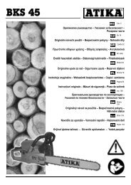
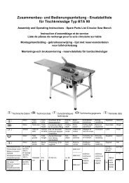
œ Adjusting between 0° - 45°<br />
1. Loosen the clamping screw (A).<br />
2. Push the handwheel (B) inward until it comes up against the<br />
stop. You can now move the saw blade until the required<br />
angle is indicated (0° - 45°).<br />
14<br />
3. Hold the handwheel in, while at the same time tightening the<br />
clamping screw, in order to set the required angle.<br />
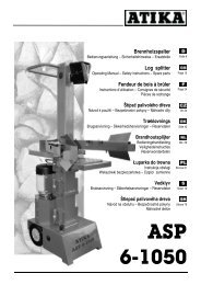
Fitting and adjusting the transverse stop<br />
The transverse stop supplied can be used as a<br />
� transverse or mitre stop.<br />
� Make sure that the fences are correctly adjusted.<br />
(See "Working instructions")<br />
œ<br />
œ<br />
2<br />
B<br />
A<br />
Fit the transverse stop to the saw table plate<br />
Push the transverse stop into one of the two grooves on<br />
the saw table plate (see picture).<br />
Setting the angle<br />
Loosen the hand grip of the transverse stop by turning.<br />
You can now set the stop to the required angle. Tighten<br />
the hand grip again.<br />
Fitting and adjusting the longitudinal stop<br />
� Make sure that the fences are correctly adjusted.<br />
(See "Working instructions")<br />
Fit the longitudinal stop (C) to the saw table plate.<br />
œ<br />
1. Hook the end of the stop rule into the rear edge of the<br />
table.<br />
2. Place the front end (handle with integrated setting<br />
magnifying glass) on the guide profile on the table.<br />
3. Set the required position with the aid of the setting<br />
magnifying glass.<br />
1.