Lieferprogramm Delivery programme - Kettenfabrik Unna GmbH ...
Lieferprogramm Delivery programme - Kettenfabrik Unna GmbH ...
Lieferprogramm Delivery programme - Kettenfabrik Unna GmbH ...

Erfolgreiche ePaper selbst erstellen
Machen Sie aus Ihren PDF Publikationen ein blätterbares Flipbook mit unserer einzigartigen Google optimierten e-Paper Software.
ISO 9001: 2008<br />
ISO 14001<br />
<strong>Kettenfabrik</strong> <strong>Unna</strong><br />
<strong>GmbH</strong> & Co. KG<br />
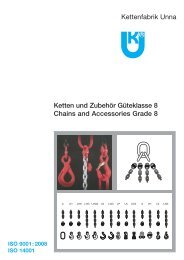
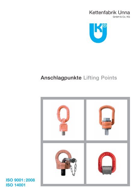
Anschlagpunkte Lifting Points
<strong>Kettenfabrik</strong> <strong>Unna</strong> wurde 1921 als Tochtergesellschaft der Union Sils van de Loo & Co., Fröndenberg, gegründet. 1925 übernahmen<br />
die beiden Prokuristen der Firma im Rahmen eines Management buy out das Unternehmen. 1928 zahlte dann einer<br />
dieser beiden Prokuristen, der Kaufmann Friedrich Jasper, den anderen aus. Seitdem ist das Unternehmen im Familienbesitz.<br />
1949 folgte mit Dr. Manfred Jasper die zweite Generation. 1991 trat mit Dr. Ingo Jasper die dritte Generation in das<br />
Unternehmen ein.<br />
<strong>Kettenfabrik</strong> <strong>Unna</strong> hat ihren Sitz seit über 30 Jahren im Industriegebiet von <strong>Unna</strong>. Der letzte Ausbau fand im Jahr 1999/2000<br />
statt – die Fläche wurde um 1.300 m 2 vergrößert. Ketten und Zubehör werden in verschiedensten Ausführungen geliefert.<br />
Der Qualitätsgedanke wird schon seit Beginn gepflegt. Dies führte zu Zulassungen verschiedener Institutionen und<br />
Abnahmegesellschaften im In- und Ausland und mündete 2002 in die Zertifizierung nach ISO 9001:2000. <strong>Kettenfabrik</strong> <strong>Unna</strong> hat<br />
sowohl im Rundstahl- als auch im Stahlgelenkkettenbereich ein komplettes Programm. Die Stahlgelenkketten wurden 1990 aufgenommen<br />
und seitdem kontinuierlich ausgebaut. <strong>Kettenfabrik</strong> <strong>Unna</strong> beliefert fast alle Branchen in vielen Ländern der Welt –<br />
der Name bürgt auch international für Qualität.<br />
<strong>Kettenfabrik</strong> <strong>Unna</strong> stehen alle modernen Kommunikationswege zur Verfügung.<br />
<strong>Kettenfabrik</strong> <strong>Unna</strong> was founded in 1921 as a daughter company of Union Sils van de Loo & Co. Fröndenberg. In 1925 the two<br />
confidential clerks took the company over with a management buy-out. In 1928 paid one of the confidential clerks, Friedrich<br />
Jasper, the other one out. Since then <strong>Kettenfabrik</strong> <strong>Unna</strong> is a completely owned family company.<br />
In 1949 followed with Dr. Manfred Jasper the second generation. With Dr. Ingo Jasper the third generation came in 1991 into<br />
the company.<br />
<strong>Kettenfabrik</strong> <strong>Unna</strong> has its site for more than 30 years in the industrial area of <strong>Unna</strong>. The last extension took place in 1999/2000<br />
– another hall was built with 1.300 m 2 . Chains and accessories are delivered in different executions worldwide.<br />
Quality was ever one of the main philosophies of <strong>Kettenfabrik</strong> <strong>Unna</strong>. This lead to different certifications of various institutions<br />
in the domestic market as well as in export markets. The last quality certificate obtained is the ISO 9001 : 2000.<br />
<strong>Kettenfabrik</strong> <strong>Unna</strong> has a complete delivery <strong>programme</strong> for link chains as well as for articulated chains. Articulated chains were<br />
taken up in the <strong>programme</strong> in 1990 and then continuously completed. <strong>Kettenfabrik</strong> <strong>Unna</strong> delivers to many branches in many<br />
countries of the world – the reputation of <strong>Kettenfabrik</strong> <strong>Unna</strong> stands for quality.<br />
<strong>Kettenfabrik</strong> <strong>Unna</strong> has all modern platforms for communication.<br />
Sprechen Sie uns an – wir sind seit 90 Jahren für Sie da<br />
Contact us – we have 90 years of experience.<br />
Besuchen Sie uns auch im Internet: www.ketten.com<br />
Please visit our website: www.chains.de<br />
2
Inhaltsverzeichnis<br />
Index<br />
Wirbelbock<br />
Swivel eyebolt<br />
APWB<br />
Wirbelbock<br />
Swivel eyebolt<br />
APWB<br />
Lastbock<br />
Eyebolt clamp<br />
APLB<br />
Drehbare Ringschraube<br />
Eyebolt twister<br />
APTW<br />
Ringschraube<br />
Rotating eyebolt<br />
APAS<br />
Ringschraube<br />
Rotating eyebolt<br />
APAL<br />
Ringmutter<br />
Rotating eye nut<br />
APAM<br />
Ringschraube variable<br />
Adjustable eyebolt 8.8<br />
APSV<br />
Ringmutter 8.8<br />
Eye nut 8.8<br />
APM8<br />
Ringschraube 8.8<br />
Eyebolt 8.8<br />
APS8<br />
����<br />
��<br />
Drehbarkeit<br />
Rotation<br />
���<br />
���<br />
��<br />
����<br />
���<br />
���<br />
���<br />
��<br />
�<br />
�<br />
– unter Last drehbar<br />
rotating under load<br />
GK<br />
Grade<br />
10<br />
Seite<br />
Page<br />
4<br />
8 6<br />
10<br />
10<br />
10<br />
10<br />
10<br />
– ausrichtbar bei Montage<br />
adjustable when assembling<br />
8<br />
8<br />
8<br />
8<br />
10<br />
12<br />
14<br />
18<br />
20<br />
21<br />
22<br />
Technische Informationen<br />
Technical Informations<br />
���<br />
�<br />
Ringschraube DIN 580<br />
Eyebolt DIN 580<br />
APSN<br />
Ringmutter DIN 582<br />
Eye nut DIN 582<br />
APMN<br />
Ringschraube DIN 580<br />
Eyebolt DIN 580<br />
APS2<br />
Ringmutter DIN 582<br />
Eye nut DIN 582<br />
APM2<br />
PSA-Ringschraube<br />
PSA Rotating eyebolt<br />
APPN<br />
PSA-Ringschraube<br />
PSA Rotating eyebolt<br />
APPL<br />
Ringöse<br />
Lifting ring<br />
SPAZ<br />
Schweißpunkt<br />
Welding point<br />
SPAB<br />
Ringöse<br />
Lifting ring<br />
SPAR<br />
Verzurr-Ringöse<br />
Lashing ring<br />
SPLB<br />
Verzurr-Ringöse<br />
Lashing ring<br />
SPLR<br />
– unter Last ausrichtbar<br />
adjustable under load<br />
– nicht drehbar<br />
not rotating<br />
Drehbarkeit<br />
Rotation<br />
GK<br />
Grade<br />
Seite<br />
Page<br />
34<br />
Es gelten unsere Verkaufsbedingungen, die wir Ihnen auf Wunsch gern nochmal zusenden.<br />
Our terms of sale are effective. Please ask for another copy if needed.<br />
Ausgabe 10/2011. Technische Änderungen und Druckfehler vorbehalten.<br />
Issue 10/2011. Subject to technical changes and printing mistakes.<br />
�<br />
�<br />
�<br />
�<br />
���<br />
���<br />
��<br />
��<br />
��<br />
��<br />
��<br />
10<br />
8<br />
10<br />
10<br />
10<br />
24<br />
25<br />
26<br />
27<br />
28<br />
30<br />
32<br />
36<br />
38<br />
40<br />
42<br />
3
4<br />
Wirbelbock, unter Last ausrichtbar - APWB / GK 10<br />
Swivel eyebolt with ring, can be oriented during loading - APWB / Grade 10<br />
Anschraubbarer, drehbarer Anschlagpunkt für das Anheben schwerer Lasten.<br />
- 4-fache Sicherheit in allen Belastungsrichtungen<br />
- Konstruiert, geprüft und zertifiziert nach GS-MO 1504 - EN 1677<br />
- Geeignet für das sichere Heben von Lasten gemäß Maschinenrichtlinie 2006/42/EG<br />
- Magnaflux-rissgeprüft zu 100%<br />
- Ausgelegt auf eine Beanspruchung von 20.000 Lastwechseln<br />
- Sondergewinde und abweichende Schaftlängen auf Anfrage<br />
- 360° drehbar - Öse 180° selbstausrichtend schwenkbar<br />
- Gelagert für eine einfachere Lastausrichtung<br />
- Bei axialem Zug ist eine Abweichung von +/-5° bei einer Reduzierung der Tragfähigkeit um 10% zulässig<br />
Turning eyebolt needed to lift loads to assemble to the load itself with specific threaded hole.<br />
- Coefficient 4 in all loading directions<br />
- Designed, tested and certified in compliance with the technical directives GS-MO 1504 – EN 1677<br />
- Suitable for safe lifting in compliance with the machinery directive 2006/42/EC<br />
- Tested at 100 % magnaflux<br />
- Tested at 20.000 stress cycles<br />
- Non standard threading and stem length upon request<br />
- Can be oriented at 360° with self aligning tilting ring at 180°<br />
- Assembled with spheres to make load orientation easier<br />
- On the axial pull there can be variation of +/-5° with a 10% decrease in capacity<br />
Nicht für Dauerdrehbewegung unter Last geeignet!<br />
Not suitable for continuous rotation movement during loading
Wirbelbock, unter Last ausrichtbar - APWB / GK 10<br />
Swivel eyebolt with ring, can be oriented during loading - APWB / Grade 10<br />
Maße / Measurements<br />
Artikel<br />
Article<br />
31716931<br />
31720931<br />
31724931<br />
31736931<br />
Tragfähigkeiten / WLLs<br />
Artikel<br />
Article<br />
31716931<br />
31720931<br />
31724931<br />
31736931<br />
Abmessung DxL<br />
Size DxL<br />
1,4 t – M 16 x20<br />
2,5 t – M 20 x30<br />
4,0 t – M 24 x30<br />
6,7 t – M 36 x54<br />
Abmessung DxL<br />
Size DxL<br />
1,4 t – M 16 x20<br />
2,5 t – M 20 x30<br />
4,0 t – M 24 x30<br />
6,7 t – M 36 x54<br />
0°<br />
1Strang<br />
Singleleg<br />
2,8<br />
5,0<br />
8,0<br />
13,4<br />
A<br />
30<br />
34<br />
40<br />
40<br />
0°<br />
2Stränge<br />
2 legs<br />
5,6<br />
10,0<br />
16,0<br />
26,8<br />
B<br />
13<br />
16<br />
19<br />
20<br />
90°<br />
1Strang<br />
Singleleg<br />
1,4<br />
2,5<br />
4,0<br />
6,7<br />
C<br />
46<br />
57<br />
70<br />
65<br />
90°<br />
2Stränge<br />
2 legs<br />
2,8<br />
5,0<br />
8,0<br />
13,4<br />
0°-45°<br />
2,00<br />
3,55<br />
5,60<br />
9,50<br />
E<br />
50<br />
50<br />
50<br />
50<br />
45°-60°<br />
2Stränge<br />
2 legs<br />
1,4<br />
2,5<br />
4,0<br />
6,7<br />
H<br />
105<br />
105<br />
105<br />
105<br />
Asym.<br />
1,4<br />
2,5<br />
4,0<br />
6,7<br />
SW<br />
30<br />
30<br />
30<br />
30<br />
0°-45°<br />
3,0<br />
5,3<br />
8,0<br />
14,0<br />
D1<br />
38<br />
38<br />
38<br />
38<br />
45°-60°<br />
4Stränge<br />
4 legs<br />
2,12<br />
3,75<br />
6,00<br />
10,00<br />
Asym.<br />
1,4<br />
2,5<br />
4,0<br />
6,7<br />
Gewicht ca. kg<br />
Weight approx.<br />
0,530<br />
1,050<br />
1,630<br />
2,230<br />
Drehmoment<br />
Tightening couple<br />
Nm<br />
70<br />
135<br />
230<br />
814<br />
5
6<br />
Wirbelbock, unter Last ausrichtbar - APWB / GK 8<br />
Swivel eyebolt with ring, can be oriented during loading - APWB / Grade 8<br />
Anschraubbarer, drehbarer Anschlagpunkt fur das Anheben schwerer Lasten.<br />
- 4-fache Sicherheit in allen Belastungsrichtungen<br />
- Konstruiert, geprüft und zertifiziert nach GS-MO 1504 - EN 1677<br />
- Geeignet fur das sichere Heben von Lasten gemaß Maschinenrichtlinie 2006/42/EG<br />
- Magnaflux-rissgeprüft zu 100%<br />
- Ausgelegt auf eine Beanspruchung von 20.000 Lastwechseln<br />
- Sondergewinde und abweichende Schaftlängen auf Anfrage<br />
- 360° drehbar - Öse 180° selbstausrichtend schwenkbar<br />
- Gelagert fur eine einfachere Lastausrichtung<br />
- Bei axialem Zug ist eine Abweichung von +/-5° bei einer Reduzierung der Tragfähigkeit um 10% zulassig<br />
Turning eyebolt needed to lift loads to assemble to the load itself with specific threaded hole.<br />
- Coefficient 4 in all loading directions<br />
- Designed, tested and certified in compliance with the technical directives GS-MO 1504 – EN 1677<br />
- Suitable for safe lifting in compliance with the machinery directive 2006/42/EC<br />
- Tested at 100 % magnaflux<br />
- Tested at 20.000 stress cycles<br />
- Non standard threading and stem length upon request<br />
- Can be oriented at 360° with self aligning tilting ring at 180°<br />
- Assembled with spheres to make load orientation easier<br />
- On the axial pull there can be variation of +/-5° with a 10% decrease in capacity<br />
Nicht für Dauerdrehbewegung unter Last geeignet!<br />
Not suitable for continuous rotation movement during loading
Wirbelbock, unter Last ausrichtbar - APWB / GK 8<br />
Rotating eyebolt with ring, can be oriented during loading - APWB / Grade 8<br />
Maße / Measurements<br />
Artikel<br />
Article<br />
31710031<br />
31712031<br />
31712032<br />
31716031<br />
31716032<br />
31720031<br />
31720131<br />
31724131<br />
31730131<br />
31730132<br />
31730231<br />
31730232<br />
31736031<br />
31742032<br />
31748031<br />
31756031<br />
31764031<br />
31772031<br />
31780031<br />
31790031<br />
Tragfähigkeiten / WLLs<br />
Artikel<br />
Article<br />
31710031<br />
31712031<br />
31712032<br />
31716031<br />
31716032<br />
31720031<br />
31720131<br />
31724131<br />
31730131<br />
31730132<br />
31730231<br />
31730232<br />
31736031<br />
31742032<br />
31748031<br />
31756031<br />
31764031<br />
31772031<br />
31780031<br />
31790031<br />
Abmessung DxL<br />
Size DxL<br />
0,30 t - M 10 x18<br />
0,50 t - M 12 x18<br />
0,50 t - M 12 x25<br />
1,12 t - M 16 x20<br />
1,12 t - M 16 x30<br />
1,12 t - M 20 x30<br />
2,00 t - M 20 x30<br />
3,15 t - M 24 x30<br />
5,30 t - M 30 x35<br />
5,30 t - M 30 x45<br />
8,00 t - M 30 x35<br />
8,00 t - M 30 x45<br />
8,00 t - M 36 x54<br />
10,00 t - M 42 x63<br />
15,00 t - M 48 x60<br />
15,00 t - M 56 x78<br />
15,00 t – M 64 x96<br />
25,00 t – M 72 x108<br />
30,00 t – M 80 x120<br />
35,00 t – M 90 x135<br />
0°<br />
1Strang<br />
Singleleg<br />
0,6<br />
1,0<br />
1,0<br />
2,0<br />
2,0<br />
2,0<br />
4,0<br />
6,3<br />
10,6<br />
10,6<br />
12,5<br />
12,5<br />
12,5<br />
15,0<br />
25,0<br />
25,0<br />
25,0<br />
35,0<br />
35,0<br />
35,0<br />
A<br />
30<br />
30<br />
30<br />
30<br />
30<br />
30<br />
34<br />
40<br />
40<br />
40<br />
50<br />
50<br />
50<br />
50<br />
70<br />
70<br />
70<br />
68<br />
68<br />
68<br />
0°<br />
2Stränge<br />
2 legs<br />
1,2<br />
2,0<br />
2,0<br />
4,0<br />
4,0<br />
4,0<br />
8,0<br />
12,5<br />
21,2<br />
21,2<br />
25,0<br />
25,0<br />
25,0<br />
30,0<br />
50,0<br />
50,0<br />
50,0<br />
70,0<br />
70,0<br />
70,0<br />
B<br />
13<br />
13<br />
13<br />
13<br />
13<br />
13<br />
16<br />
19<br />
20<br />
20<br />
22<br />
22<br />
22<br />
22<br />
30<br />
30<br />
30<br />
40<br />
40<br />
40<br />
90°<br />
1Strang<br />
Singleleg<br />
0,30<br />
0,50<br />
0,50<br />
1,12<br />
1,12<br />
1,12<br />
2,00<br />
3,15<br />
5,30<br />
5,30<br />
8,00<br />
8,00<br />
8,00<br />
10,00<br />
15,00<br />
15,00<br />
15,00<br />
25,00<br />
30,00<br />
35,00<br />
C<br />
46<br />
46<br />
46<br />
46<br />
46<br />
46<br />
57<br />
70<br />
65<br />
65<br />
90<br />
90<br />
90<br />
90<br />
120<br />
120<br />
120<br />
127<br />
127<br />
127<br />
90°<br />
2Stränge<br />
2 legs<br />
0,6<br />
1,0<br />
1,0<br />
2,0<br />
2,0<br />
2,0<br />
4,0<br />
6,3<br />
10,6<br />
10,6<br />
16,0<br />
16,0<br />
16,0<br />
20,0<br />
30,0<br />
30,0<br />
30,0<br />
50,0<br />
50,0<br />
70,0<br />
0°-45°<br />
0,42<br />
0,75<br />
0,75<br />
1,50<br />
1,50<br />
1,50<br />
2,80<br />
4,25<br />
7,10<br />
7,10<br />
11,20<br />
11,20<br />
11,20<br />
14,00<br />
21,00<br />
21,00<br />
21,00<br />
35,00<br />
42,00<br />
49,00<br />
E<br />
50<br />
50<br />
50<br />
50<br />
50<br />
50<br />
61<br />
68<br />
80<br />
80<br />
95<br />
95<br />
95<br />
95<br />
130<br />
130<br />
130<br />
165<br />
165<br />
165<br />
45°-60°<br />
2Stränge<br />
2 legs<br />
0,30<br />
0,50<br />
0,50<br />
1,12<br />
1,12<br />
1,12<br />
2,00<br />
3,15<br />
5,30<br />
5,30<br />
8,00<br />
8,00<br />
8,00<br />
10,00<br />
15,00<br />
15,00<br />
15,00<br />
25,00<br />
30,00<br />
35,00<br />
H<br />
105<br />
105<br />
105<br />
105<br />
105<br />
105<br />
131<br />
153<br />
165<br />
165<br />
205<br />
205<br />
205<br />
205<br />
280<br />
280<br />
280<br />
338<br />
338<br />
338<br />
Asym.<br />
0,30<br />
0,50<br />
0,50<br />
1,12<br />
1,12<br />
1,12<br />
2,00<br />
3,15<br />
5,30<br />
5,30<br />
8,00<br />
8,00<br />
8,00<br />
10,00<br />
15,00<br />
15,00<br />
15,00<br />
25,00<br />
30,00<br />
35,00<br />
SW<br />
30<br />
30<br />
30<br />
30<br />
30<br />
30<br />
40<br />
48<br />
65<br />
65<br />
75<br />
75<br />
75<br />
75<br />
95<br />
95<br />
95<br />
134<br />
134<br />
134<br />
0°-45°<br />
0,63<br />
1,10<br />
1,10<br />
2,36<br />
2,36<br />
2,36<br />
4,00<br />
6,30<br />
11,20<br />
11,20<br />
16,80<br />
16,80<br />
16,80<br />
21,20<br />
31,50<br />
31,50<br />
31,50<br />
52,50<br />
63,00<br />
73,50<br />
D1<br />
38<br />
38<br />
38<br />
38<br />
38<br />
38<br />
50<br />
58<br />
75<br />
75<br />
85<br />
85<br />
85<br />
85<br />
120<br />
120<br />
120<br />
160<br />
170<br />
170<br />
45°-60°<br />
4Stränge<br />
4 legs<br />
0,45<br />
0,75<br />
0,75<br />
1,60<br />
1,60<br />
1,60<br />
3,00<br />
4,75<br />
8,00<br />
8,00<br />
12,00<br />
12,00<br />
12,00<br />
15,00<br />
22,50<br />
22,50<br />
22,50<br />
37,50<br />
45,00<br />
52,50<br />
Asym.<br />
0,30<br />
0,50<br />
0,50<br />
1,12<br />
1,12<br />
1,12<br />
2,00<br />
3,15<br />
5,30<br />
5,30<br />
8,00<br />
8,00<br />
8,00<br />
10,00<br />
15,00<br />
15,00<br />
15,00<br />
25,00<br />
30,00<br />
35,00<br />
Gewicht ca. kg<br />
Weight approx.<br />
0,480<br />
0,500<br />
0,500<br />
0,530<br />
0,530<br />
0,530<br />
1,050<br />
1,630<br />
2,230<br />
2,230<br />
5,300<br />
5,300<br />
5,500<br />
10,000<br />
10,000<br />
10,000<br />
10,000<br />
29,000<br />
29,000<br />
29,000<br />
Drehmoment<br />
Tightening couple<br />
Nm<br />
16<br />
28<br />
28<br />
70<br />
70<br />
135<br />
135<br />
230<br />
465<br />
465<br />
465<br />
465<br />
814<br />
1304<br />
1981<br />
3000<br />
4738<br />
6913<br />
9625<br />
14000<br />
7
8<br />
Ausführung mit<br />
Standardschraube<br />
Available with<br />
standard screws<br />
Anschlagpunkt zum Heben von Lasten.<br />
Lastbock, Lastrichtung 90° bei minimalem Platzbedarf - APLB / GK 10<br />
Eyebolt clamp, pull at 90° with minimum overall dimensions - APLB / Grade 10<br />
- 4-fache Sicherheit in allen Belastungsrichtungen<br />
- Konstruiert, geprüft und zertifiziert nach GS-MO 1504 - EN 1677<br />
- Geeignet für das sichere Heben von Lasten gemäß Maschinenrichtlinie 2006/42/EG<br />
- 360° drehbar, 90° schwenkbar<br />
- Magnaflux-rissgeprüft zu 100%<br />
- Ausgelegt auf eine Beanspruchung von 20.000 Lastwechseln<br />
- Schraube dauerhaft korrosionsgeschützt mit GEOMET<br />
- Sondergewinde und abweichende Schaftlängen auf Anfrage<br />
- Ideal als 90°-Anschlagpunkt<br />
- Unverlierbare Schraube<br />
- Lastbockschrauben mit Nenndurchmesser M 36 oder größer können auch mit<br />
Univeral-Sechskantschlüsseln angeschraubt werden<br />
Anchorage point for load lifting.<br />
Ausführung mit<br />
Sonderschraube<br />
Available with non<br />
standard screws<br />
- Safety coefficient 4 in all loading directions<br />
- Designed, tested and certified in compliance with the technical directives GS-MO 1504 – EN 1677<br />
- Suitable for safe lifting in compliance with the machinery directive 2006/42/EC<br />
- 360° turnable, 90° traversable<br />
- Tested at 100 % magnaflux<br />
- Tested at 20.000 stress cycles<br />
- The screw is protected with the GEOMET system which guarantees lasting protection in time<br />
- Non standard threading and stem length upon request<br />
- Ideal for fastening at 90°<br />
- Captive screws<br />
- Eyebolt screws size M36 or bigger have been realized also to hexagonal universal spanners<br />
Achtung: Anschlagpunkt nicht für das Drehen unter Last geeignet!<br />
Warning: the device is not suitable for rotation during loading
Lastbock, Lastrichtung 90° bei minimalem Platzbedarf - APLB / GK 10<br />
Eyebolt clamp, pull at 90° with minimum overall dimensions - APLB / Grade 10<br />
Maße / Measurements<br />
Artikel<br />
Article<br />
31708041<br />
31710041<br />
31712041<br />
31716041<br />
31720041<br />
31724041<br />
31727041<br />
31730041<br />
31736040<br />
31736041<br />
31742040<br />
31742041<br />
31748041<br />
Abmessung DxL<br />
Size DxL<br />
M 8-0,30 t<br />
M 10-0,63 t<br />
M 12-1,00 t<br />
M 16-1,50 t<br />
M 20-2,50 t<br />
M 24-4,00 t<br />
M 27-4,00 t<br />
M 30-5,00 t<br />
M 36-7,00 t<br />
M 36-8,00 t<br />
M 42-10,00 t<br />
M 42-15,00 t<br />
M 48-20,00 t<br />
Tragfähigkeiten / WLLs<br />
Artikel<br />
Article<br />
31708041<br />
31710041<br />
31712041<br />
31716041<br />
31720041<br />
31724041<br />
31727041<br />
31730041<br />
31736040<br />
31736041<br />
31742040<br />
31742041<br />
31748041<br />
A<br />
57<br />
57<br />
66<br />
66<br />
87<br />
87<br />
109<br />
109<br />
109<br />
136<br />
136<br />
169<br />
169<br />
Abmessung DxL<br />
Size DxL<br />
M 8<br />
M 10<br />
M 12<br />
M 16<br />
M 20<br />
M 24<br />
M 27<br />
M 30<br />
M 36<br />
M 36<br />
M 42<br />
M 42<br />
M 48<br />
B<br />
34<br />
34<br />
38<br />
38<br />
55<br />
55<br />
66<br />
66<br />
66<br />
78<br />
78<br />
97<br />
97<br />
C<br />
10,0<br />
10,0<br />
13,5<br />
13,5<br />
16,0<br />
16,0<br />
22,5<br />
22,5<br />
22,5<br />
28,0<br />
28,0<br />
36,0<br />
36,0<br />
0°<br />
1Strang<br />
Singleleg<br />
0,30<br />
0,63<br />
1,00<br />
1,50<br />
2,50<br />
4,00<br />
4,00<br />
5,00<br />
7,00<br />
8,00<br />
10,00<br />
15,00<br />
20,00<br />
D<br />
78<br />
78<br />
85<br />
85<br />
111<br />
111<br />
145<br />
145<br />
145<br />
190<br />
190<br />
242<br />
242<br />
0°<br />
2Stränge<br />
2 legs<br />
0,60<br />
1,26<br />
2,00<br />
3,00<br />
5,00<br />
8,00<br />
8,00<br />
10,00<br />
14,00<br />
16,00<br />
20,00<br />
30,00<br />
40,00<br />
E<br />
24<br />
24<br />
30<br />
30<br />
48<br />
48<br />
54<br />
54<br />
54<br />
62<br />
62<br />
68<br />
68<br />
90°<br />
1Strang<br />
Singleleg<br />
0,30<br />
0,63<br />
1,00<br />
1,50<br />
2,50<br />
4,00<br />
4,00<br />
5,00<br />
7,00<br />
8,00<br />
10,00<br />
15,00<br />
20,00<br />
F<br />
41<br />
41<br />
50<br />
50<br />
68<br />
68<br />
91<br />
91<br />
91<br />
108<br />
108<br />
131<br />
131<br />
90°<br />
2Stränge<br />
2 legs<br />
0,60<br />
1,26<br />
2,00<br />
3,00<br />
5,00<br />
8,00<br />
8,00<br />
10,00<br />
14,00<br />
16,00<br />
20,00<br />
30,00<br />
40,00<br />
G<br />
30<br />
30<br />
36<br />
36<br />
44<br />
44<br />
63<br />
65<br />
55<br />
81<br />
75<br />
89<br />
89<br />
0°-45°<br />
0,42<br />
0,88<br />
1,40<br />
2,10<br />
3,50<br />
5,60<br />
5,60<br />
7,00<br />
9,80<br />
11,20<br />
14,00<br />
21,00<br />
28,00<br />
H<br />
26,5<br />
26,5<br />
33,0<br />
33,0<br />
42,5<br />
42,5<br />
58,5<br />
58,5<br />
58,5<br />
72,5<br />
72,5<br />
87,5<br />
87,5<br />
I<br />
25<br />
25<br />
32<br />
32<br />
45<br />
45<br />
60<br />
60<br />
60<br />
70<br />
70<br />
85<br />
95<br />
45°-60°<br />
2Stränge<br />
2 legs<br />
0,30<br />
0,63<br />
1,00<br />
1,50<br />
2,50<br />
4,00<br />
4,00<br />
5,00<br />
7,00<br />
8,00<br />
10,00<br />
15,00<br />
20,00<br />
L<br />
15<br />
15<br />
23<br />
24<br />
31<br />
37<br />
37<br />
45<br />
50<br />
59<br />
75<br />
61<br />
71<br />
Asym.<br />
0,30<br />
0,63<br />
1,00<br />
1,50<br />
2,50<br />
4,00<br />
4,00<br />
5,00<br />
7,00<br />
8,00<br />
10,00<br />
15,00<br />
20,00<br />
W<br />
43<br />
42<br />
40<br />
38<br />
54<br />
51<br />
64<br />
62<br />
60<br />
88<br />
86<br />
121<br />
117<br />
0°-45°<br />
0,63<br />
1,32<br />
2,10<br />
3,15<br />
5,25<br />
8,40<br />
8,40<br />
10,50<br />
14,70<br />
16,80<br />
21,00<br />
31,50<br />
42,00<br />
J<br />
51<br />
51<br />
52<br />
52<br />
71<br />
71<br />
86<br />
86<br />
86<br />
115<br />
115<br />
151<br />
151<br />
45°-60°<br />
4Stränge<br />
4 legs<br />
0,45<br />
0,95<br />
1,50<br />
2,25<br />
3,75<br />
6,00<br />
6,00<br />
7,50<br />
10,40<br />
12,00<br />
15,00<br />
22,50<br />
30,00<br />
K<br />
35<br />
35<br />
28<br />
28<br />
36<br />
36<br />
47<br />
47<br />
43<br />
74<br />
70<br />
97<br />
93<br />
Asym.<br />
0,30<br />
0,63<br />
1,00<br />
1,50<br />
2,50<br />
4,00<br />
4,00<br />
5,00<br />
7,00<br />
8,00<br />
10,00<br />
15,00<br />
20,00<br />
Ch<br />
13<br />
17<br />
19<br />
24<br />
30<br />
36<br />
41<br />
46<br />
55<br />
55<br />
65<br />
65<br />
75<br />
Gewicht ca. kg<br />
Weight approx.<br />
0,275<br />
0,290<br />
0,500<br />
0,510<br />
1,250<br />
1,300<br />
3,150<br />
3,250<br />
3,300<br />
5,900<br />
6,500<br />
11,200<br />
11,600<br />
Drehmoment<br />
Tightening couple<br />
Nm<br />
30<br />
60<br />
100<br />
150<br />
250<br />
400<br />
400<br />
500<br />
700<br />
800<br />
925<br />
1500<br />
2000<br />
9
10<br />
Drehbare Ringschraube, kugelgelagert, geeignet für Dauerdrehbewegungen - APTW / GK 10<br />
Eyebolt twister with bearing, rotation allowed during continuous loading - APTW / Grade 10<br />
Anschlagpunkt zum Heben von Lasten, geeignet für Dauerdrehbewegungen unter Tragfähigkeit in axialer Zugrichtung.<br />
- 4-fache Sicherheit in allen Belastungsrichtungen<br />
- Konstruiert, geprüft und zertifiziert nach GS-MO 1504 - EN 1677<br />
- Geeignet für das sichere Heben von Lasten gemäß Maschinenrichtlinie 2006/42/EG<br />
- 360° drehbar<br />
- Magnaflux-rissgeprüft zu 100%<br />
- Ausgelegt auf eine Beanspruchung von 20.000 Lastwechseln<br />
- Ideal für das Drehen von Lasten<br />
- Unverlierbare Schraube<br />
- Der Anschlag ist nur in axialer Zugrichtung für Drehbewegungen geeignet; in allen anderen Belastungsrichtungen kann die<br />
Ringschraube in jedem Fall nichtdrehend verwendet werden (Lasten siehe Auslegungstabelle)<br />
Fastening points for lifting loads suitable for continuous rotation during loading with axial pull.<br />
- Safety coefficient 4 in all loading directions<br />
- Designed, tested and certified in compliance with the technical directives GS-MO 1504 – EN 1677<br />
- Suitable for safe lifting in compliance with the machinery directive 2006/42/EC<br />
- Can be oriented at 360°<br />
- Tested at 100 % magnaflux<br />
- Tested at 20.000 stress cycles<br />
- Ideal for rotation during loading<br />
- Captive screws<br />
- The device is suitable for rotation during loading only with axial pull; the eyebolt can be used in every other pull direction<br />
without rotation (for loads see reference table)<br />
Maximale Drehzahl unter Tragkraft 50 U/min!<br />
Do not exceed during rotation phase loads 50 rpm<br />
(Position erfüllt in jedem Fall die Normanforderung<br />
der 4-fachen Sicherheit)<br />
(Position which is in compliance with the safety<br />
coefficient 4 as per the related technical directives)
Drehbare Ringschraube, kugelgelagert, geeignet für Dauerdrehbewegungen - APTW / GK 10<br />
Eyebolt twister with bearing, rotation allowed during continuous loading - APTW / Grade 10<br />
Maße / Measurements<br />
Artikel ohne Schlüssel<br />
Article without key<br />
31712051<br />
31716051<br />
31720051<br />
31724051<br />
31730051<br />
Artikel mit Schlüssel<br />
Article with key<br />
31712051S<br />
31716051S<br />
31720051S<br />
31724051S<br />
31730051S<br />
Tragfähigkeiten / WLLs<br />
Artikel ohne<br />
Schlüssel<br />
Article without key<br />
31712051<br />
31716051<br />
31720051<br />
31724051<br />
31730051<br />
Artikel mit<br />
Schlüssel<br />
Article with key<br />
31712051S<br />
31716051S<br />
31720051S<br />
31724051S<br />
31730051S<br />
Abmessung<br />
DxL<br />
Size DxL<br />
M 12<br />
M 16<br />
M 20<br />
M 24<br />
M 30<br />
Abmessung<br />
DxL<br />
Size DxL<br />
M 12<br />
M 16<br />
M 20<br />
M 24<br />
M 30<br />
0°<br />
*<br />
0,75<br />
1,50<br />
2,30<br />
3,20<br />
4,50<br />
M-WLL<br />
0,75<br />
1,50<br />
2,50<br />
3,20<br />
4,50<br />
0°<br />
2Stränge<br />
2 legs<br />
1,5<br />
3,0<br />
4,6<br />
6,4<br />
9,0<br />
A<br />
53,5<br />
56,5<br />
67,0<br />
80,0<br />
101,0<br />
90°<br />
1Strang<br />
Singleleg<br />
0,75<br />
1,50<br />
2,30<br />
3,20<br />
4,50<br />
B<br />
11<br />
13<br />
14<br />
18<br />
22<br />
90°<br />
2Stränge<br />
2 legs<br />
1,5<br />
3,0<br />
4,6<br />
6,4<br />
9,0<br />
C<br />
11,0<br />
14,5<br />
17,0<br />
19,0<br />
27,0<br />
0°-45°<br />
1,00<br />
2,00<br />
3,22<br />
4,48<br />
6,30<br />
D<br />
34<br />
39<br />
42<br />
52<br />
62<br />
45°-60°<br />
2Stränge<br />
2 legs<br />
0,75<br />
1,50<br />
2,30<br />
3,20<br />
4,50<br />
E<br />
44<br />
56<br />
58<br />
73<br />
80<br />
Asym.<br />
0,75<br />
1,50<br />
2,30<br />
3,20<br />
4,50<br />
* Axialer Zug mit Dauerdrehbewegung unter Last<br />
* Axial pull with rotation during continuous loading<br />
Sonderschlüssel für Abmessungen von M12 bis M30<br />
Special key for sizes from M12 to M30<br />
Artikel<br />
Article<br />
317S12TW<br />
317S16TW<br />
317S20TW<br />
317S24TW<br />
317S30TW<br />
F<br />
32,0<br />
33,0<br />
40,0<br />
44,5<br />
53,0<br />
0°-45°<br />
1,60<br />
3,15<br />
4,83<br />
6,70<br />
9,40<br />
K<br />
56<br />
65<br />
70<br />
88<br />
106<br />
45°-60°<br />
4Stränge<br />
4 legs<br />
1,12<br />
2,25<br />
3,45<br />
4,80<br />
6,70<br />
Asym.<br />
0,75<br />
1,50<br />
2,30<br />
3,20<br />
4,50<br />
L<br />
18,0<br />
24,0<br />
30,0<br />
38,5<br />
44,0<br />
Abmessung<br />
Size<br />
M 12<br />
M 16<br />
M 20<br />
M 24<br />
M 30<br />
Gewicht ca. kg<br />
Weight approx.<br />
0,460<br />
0,900<br />
1,150<br />
2,050<br />
4,000<br />
Drehmoment<br />
Tightening couple<br />
Nm<br />
28<br />
70<br />
135<br />
230<br />
465<br />
11
Anschlagpunkt zum Heben von Lasten.<br />
12<br />
Ringschraube, unter Last ausrichtbar - APAS / GK 10<br />
Rotating eyebolt, adjustable under load - APAS / Grade 10<br />
- 4-fache Sicherheit in allen Belastungsrichtungen<br />
- Konstruiert, geprüft und zertifiziert nach GS-MO 1504 - EN 1677<br />
- Geeignet für das sichere Heben von Lasten gemäß Maschinenrichtlinie 2006/42/EG<br />
- 360° drehbar<br />
- Magnaflux-rissgeprüft zu 100%<br />
- Ausgelegt auf eine Beanspruchung von 20.000 Lastwechseln<br />
- Ideal als 90°-Anschlagpunkt<br />
- Unverlierbare Schraube<br />
- Bei axialem Zug ist eine Abweichung von +/-5° bei einer Reduzierung der Tragfähigkeit um 10% zulässig<br />
Anchorage point for load lifting.<br />
- Safety coefficient 4 in all loading directions<br />
- Designed, tested and certified in compliance with the technical directives GS-MO 1504 – EN 1677<br />
- Suitable for safe lifting in compliance with the machinery directive 2006/42/EC<br />
- Can be oriented at 360°<br />
- Tested at 100 % magnaflux<br />
- Tested at 20.000 stress cycles<br />
- Ideal for fastening at 90°<br />
- Captive screws<br />
- On the axial pull there can be variation of +/-5° with a 10% decrease in capacity<br />
Achtung: Anschlagpunkt nicht für das Drehen unter Last geeignet!<br />
Warning: the device is not suitable for rotation during loading<br />
(Position erfüllt in jedem Fall die Normanforderung<br />
der 4-fachen Sicherheit)<br />
(Position which is in compliance with the safety<br />
coefficient 4 as per the related technical directives)
Ringschraube, unter Last ausrichtbar - APAS / GK 10<br />
Rotating eyebolt, adjustable under load - APAS / Grade 10<br />
Maße / Measurements<br />
Artikel ohne Schlüssel<br />
Article without key<br />
31708021<br />
31710021<br />
31712021<br />
31716021<br />
31720021<br />
31724021<br />
31730021<br />
31736021<br />
31742021<br />
31748021<br />
Artikel mit Schlüssel<br />
Article with key<br />
31708021S<br />
31710021S<br />
31712021S<br />
31716021S<br />
31720021S<br />
31724021S<br />
31730021S<br />
31736021S<br />
31742021S<br />
31748021S<br />
Tragfähigkeiten / WLLs<br />
Artikel ohne<br />
Schlüssel<br />
Article without key<br />
31708021<br />
31710021<br />
31712021<br />
31716021<br />
31720021<br />
31724021<br />
31730021<br />
31736021<br />
31742021<br />
31748021<br />
Artikel<br />
mit Schlüssel<br />
Article with key<br />
31708021S<br />
31710021S<br />
31712021S<br />
31716021S<br />
31720021S<br />
31724021S<br />
31730021S<br />
31736021S<br />
31742021S<br />
31748021S<br />
Abmessung<br />
DxL<br />
Size DxL<br />
M 8<br />
M 10<br />
M 12<br />
M 16<br />
M 20<br />
M 24<br />
M 30<br />
M 36<br />
M 42<br />
M 48<br />
Abmessung<br />
DxL<br />
Size DxL<br />
M 8<br />
M 10<br />
M 12<br />
M 16<br />
M 20<br />
M 24<br />
M 30<br />
M 36<br />
M 42<br />
M 48<br />
0°<br />
1Strang<br />
Singleleg<br />
1<br />
1<br />
2<br />
4<br />
6<br />
8<br />
12<br />
16<br />
24<br />
32<br />
M-WLL<br />
0,30<br />
0,40<br />
0,75<br />
1,50<br />
2,50<br />
3,20<br />
4,50<br />
7,00<br />
9,00<br />
12,00<br />
0°<br />
2Stränge<br />
2 legs<br />
2<br />
2<br />
4<br />
8<br />
12<br />
16<br />
24<br />
32<br />
45<br />
64<br />
A<br />
44,5<br />
44,5<br />
53,5<br />
56,5<br />
67,0<br />
80,0<br />
101,0<br />
125,0<br />
148,0<br />
165,0<br />
90°<br />
1Strang<br />
Singleleg<br />
0,30<br />
0,40<br />
0,75<br />
1,50<br />
2,30<br />
3,20<br />
4,50<br />
7,00<br />
9,00<br />
12,00<br />
B<br />
8<br />
8<br />
11<br />
13<br />
14<br />
18<br />
22<br />
37<br />
40<br />
45<br />
90°<br />
2Stränge<br />
2 legs<br />
0,6<br />
0,8<br />
1,5<br />
3,0<br />
4,6<br />
6,4<br />
9,0<br />
14,0<br />
18,0<br />
24,0<br />
C<br />
10,0<br />
10,0<br />
11,0<br />
14,5<br />
17,0<br />
19,0<br />
27,0<br />
38,0<br />
41,0<br />
47,0<br />
0°-45°<br />
0,42<br />
0,56<br />
1,00<br />
2,00<br />
3,22<br />
4,48<br />
6,30<br />
9,80<br />
12,60<br />
16,80<br />
D<br />
29<br />
29<br />
34<br />
39<br />
42<br />
52<br />
62<br />
80<br />
90<br />
95<br />
45°-60°<br />
2Stränge<br />
2 legs<br />
0,30<br />
0,40<br />
0,75<br />
1,50<br />
2,30<br />
3,20<br />
4,50<br />
7,00<br />
9,00<br />
12,00<br />
Asym.<br />
0,30<br />
0,40<br />
0,75<br />
1,50<br />
2,30<br />
3,20<br />
4,50<br />
7,00<br />
9,00<br />
12,00<br />
E<br />
32<br />
32<br />
44<br />
56<br />
58<br />
73<br />
80<br />
95<br />
105<br />
120<br />
0°-45°<br />
0,63<br />
0,84<br />
1,60<br />
3,15<br />
4,83<br />
6,70<br />
9,40<br />
14,70<br />
18,90<br />
25,20<br />
K<br />
45<br />
45<br />
56<br />
65<br />
70<br />
88<br />
106<br />
154<br />
170<br />
185<br />
45°-60°<br />
4Stränge<br />
4 legs<br />
0,45<br />
0,60<br />
1,12<br />
2,25<br />
3,45<br />
4,80<br />
6,70<br />
10,50<br />
13,50<br />
18,00<br />
L<br />
12<br />
16<br />
18<br />
24<br />
30<br />
36<br />
43<br />
54<br />
64<br />
72<br />
Asym.<br />
0,30<br />
0,40<br />
0,75<br />
1,50<br />
2,30<br />
3,20<br />
4,50<br />
7,00<br />
9,00<br />
12,00<br />
Sonderschlüssel für Abmessungen von M8 bis M30<br />
Special key for sizes from M8 to M30<br />
Artikel<br />
Article<br />
317S08AS<br />
317S10AS<br />
317S12AS<br />
317S16AS<br />
317S20AS<br />
317S24AS<br />
317S30AS<br />
Abmessung<br />
Size<br />
M 8<br />
M 10<br />
M 12<br />
M 16<br />
M 20<br />
M 24<br />
M 30<br />
Gewicht ca. kg<br />
Weight approx.<br />
0,300<br />
0,300<br />
0,460<br />
0,900<br />
1,150<br />
2,050<br />
4,000<br />
6,700<br />
9,500<br />
13,400<br />
Drehmoment<br />
Tightening couple<br />
Nm<br />
8<br />
16<br />
28<br />
70<br />
135<br />
230<br />
465<br />
814<br />
1304<br />
1981<br />
13
14<br />
Ringschraube mit unterschiedlicher Schraubenlänge, unter Last ausrichtbar - APAL / GK 10<br />
Rotating eyebolt with variable screw length, adjustable under load - APAL / Grade 10<br />
Unverlierbarer Schraubenschlüssel getrennt bestellbar<br />
Spanner kit to be ordered separately<br />
Unterlegscheibensatz DIN 6340 + hohe Sechskantmutter<br />
UNI 5587 Festigkeitskl. 10 getrennt bestellbar<br />
Washer kit DIN 6340 + High nut UNI 5587 cl10 to be<br />
ordered separately<br />
Anschlagpunkt zum Heben von Lasten geeignet für Durchgangsbohrungen und/oder Gewindesacklöcher.<br />
- 4-fache Sicherheit in allen Belastungsrichtungen<br />
- Konstruiert, geprüft und zertifiziert nach GS-MO 1504 - EN 1677<br />
- Geeignet für das sichere Heben von Lasten gemäß Maschinenrichtlinie 2006/42/EG<br />
- 360° drehbar<br />
- Magnaflux-rissgeprüft zu 100%<br />
- Ausgelegt auf eine Beanspruchung von 20.000 Lastwechseln<br />
- Innensechskant-Zylinderkopfschraube Festigkeitskl. 10.9 mit unterschiedlichen Schraubenlängen nach UNI 5931 - DIN 912<br />
- Es wird empfohlen, unter der Sechskantmutter eine ausreichend große Unterlegscheibe nach DIN 6340 zu verwenden.<br />
- Bei axialem Zug ist eine Abweichung von +/-5° bei einer Reduzierung der Tragfähigkeit um 10% zulässig<br />
- Sollte die Ringschraube beim Einbau mit einer Kontermutter befestigt werden, muss das von einer zur anderen Seite<br />
reichende Bohrloch an dem Teil, das angehoben werden soll, maximal 2 mm breiter sein als die Nennweite der verwendeten<br />
Schraube.<br />
- Sollte eine Kontermutter verwendet werden, überprüfen Sie, dass nach ihrem Einbau sowohl die Grundfläche der<br />
Vorrichtung, als auch die Grundfläche der Gegenmutter vollkommen auf der Oberfläche des Teils aufliegt, das angehoben<br />
werden soll.<br />
Anchorage point used to lift loads with through holes and/or threaded dead holes.<br />
- Safety coefficient 4 in all loading directions<br />
- Designed, tested and certified in compliance with the technical directives GS-MO 1504 – EN 1677<br />
- Suitable for safe lifting in compliance with the machinery directive 2006/42/EC<br />
- Can be oriented at 360°<br />
- Tested at 100 % magnaflux<br />
- Tested at 20.000 stress cycles<br />
- Cylinder head screw with hexagonal slot cl. 10.9 with variable length in compliance with directive UNI5931-DIN912<br />
- We recommend the use of a washer DIN 6340 with appropriate dimensions to apply against the nut.<br />
- On the axial pull there can be variation of +/-5° with a 10% decrease in capacity<br />
- If the eyebolt is installed against the nut it has to be high and the through hole has to be on the part to be lifted with a dia<br />
meter maximum with respect to the nominal diameter of the screw used<br />
- When using a counter-nut, check that, once installed, both the base of the device and the base of the counter nut are totally in<br />
contact with the surface of the part to be lifted.
Ringschraube mit unterschiedlicher Schraubenlänge, unter Last ausrichtbar - APAL / GK 10<br />
Rotating eyebolt with variable screw length, adjustable under load - APAL / Grade 10<br />
Maße / Measurements<br />
Artikel<br />
Article<br />
31708121<br />
31710121<br />
31712121<br />
31716121<br />
31720121<br />
31724121<br />
31730121<br />
Tragfähigkeiten / WLLs<br />
Artikel<br />
Article<br />
31708121<br />
31710121<br />
31712121<br />
31716121<br />
31720121<br />
31724121<br />
31730121<br />
Abmessung<br />
Size<br />
M 8<br />
M 10<br />
M 12<br />
M 16<br />
M 20<br />
M 24<br />
M 30<br />
Abmessung DxL<br />
Size DxL<br />
M 8<br />
M 10<br />
M 12<br />
M 16<br />
M 20<br />
M 24<br />
M 30<br />
s.w.l. / t<br />
0,40<br />
0,40<br />
0,75<br />
1,50<br />
2,30<br />
3,20<br />
4,50<br />
0°<br />
1Strang<br />
Singleleg<br />
1<br />
1<br />
2<br />
4<br />
6<br />
8<br />
12<br />
0°<br />
2Stränge<br />
2 legs<br />
2<br />
2<br />
4<br />
8<br />
12<br />
16<br />
24<br />
A<br />
44,5<br />
44,5<br />
53,5<br />
59,5<br />
67,0<br />
80,0<br />
101,0<br />
90°<br />
1Strang<br />
Singleleg<br />
0,30<br />
0,40<br />
0,75<br />
1,50<br />
2,30<br />
3,20<br />
4,50<br />
90°<br />
2Stränge<br />
2 legs<br />
0,6<br />
0,8<br />
1,5<br />
3,0<br />
4,6<br />
6,4<br />
9,0<br />
B<br />
8<br />
8<br />
11<br />
13<br />
14<br />
18<br />
22<br />
0°-45°<br />
0,42<br />
0,56<br />
1,00<br />
2,00<br />
3,22<br />
4,48<br />
6,30<br />
C<br />
10,0<br />
10,0<br />
11,0<br />
14,5<br />
17,0<br />
19,0<br />
27,0<br />
45°-60°<br />
2Stränge<br />
2 legs<br />
0,30<br />
0,40<br />
0,75<br />
1,50<br />
2,30<br />
3,20<br />
4,50<br />
Asym.<br />
0,30<br />
0,40<br />
0,75<br />
1,50<br />
2,30<br />
3,20<br />
4,50<br />
D<br />
29<br />
29<br />
34<br />
39<br />
42<br />
52<br />
62<br />
0°-45°<br />
0,63<br />
0,84<br />
1,60<br />
3,15<br />
4,83<br />
6,70<br />
9,40<br />
E<br />
32<br />
32<br />
44<br />
56<br />
58<br />
73<br />
80<br />
45°-60°<br />
4Stränge<br />
4 legs<br />
0,45<br />
0,60<br />
1,12<br />
2,25<br />
3,45<br />
4,80<br />
6,70<br />
Asym.<br />
0,30<br />
0,40<br />
0,75<br />
1,50<br />
2,30<br />
3,20<br />
4,50<br />
K<br />
45<br />
45<br />
56<br />
65<br />
70<br />
88<br />
106<br />
L<br />
10,5<br />
6,5<br />
8,0<br />
8,5<br />
10,5<br />
13,5<br />
17,0<br />
Drehmoment<br />
Tightening couple<br />
Nm<br />
Die Ringschraube darf auf keinen Fall mit Schrauben unpassender Länge verwendet werden, durch die die Vorrichtung nicht<br />
korrekt befestigt wird – Falsche Verwendung: siehe Abbildung<br />
The eyebolt cannot in any way be used with screws of an inappropriate length that prevent the correct fixing of the device –<br />
see diagram for non correct use<br />
Kontermuttern mit mindestens Festigkeitsklasse10 verwenden!<br />
Achtung: Anschlagpunkt nicht für das Drehen unter Last geeignet!<br />
Do not use a counter-nut inferior to 10<br />
Warning : the device is not suitable for rotation during loading<br />
8<br />
16<br />
28<br />
70<br />
135<br />
230<br />
465<br />
(Position erfüllt in jedem Fall die Normanforderung<br />
der 4-fachen Sicherheit)<br />
(Position which is in compliance with the safety<br />
coefficient 4 as per the related technical directives)<br />
15
16<br />
d filett. standard<br />
Max.<br />
Max.<br />
dk Min.<br />
Max.<br />
K Min.<br />
Max.<br />
ds Min.<br />
s nominale<br />
e Min.<br />
H<br />
l Nom<br />
12<br />
14<br />
16<br />
18<br />
20<br />
22<br />
25<br />
30<br />
35<br />
40<br />
45<br />
50<br />
55<br />
60<br />
65<br />
70<br />
75<br />
80<br />
85<br />
90<br />
100<br />
110<br />
120<br />
130<br />
140<br />
150<br />
160<br />
180<br />
200<br />
220<br />
240<br />
lg Max.<br />
3,75<br />
3,75<br />
3,75<br />
3,75<br />
3,75<br />
3,75<br />
3,75<br />
3,75<br />
3,75<br />
12,00<br />
17,00<br />
22,00<br />
27,00<br />
32,00<br />
37,00<br />
42,00<br />
47,00<br />
52,00<br />
57,00<br />
62,00<br />
72,00<br />
82,00<br />
92,00<br />
102,00<br />
112,00<br />
122,00<br />
132,00<br />
152,00<br />
M 8<br />
13,00<br />
13,27<br />
12,73<br />
8,00<br />
7,64<br />
8,00<br />
7,78<br />
6,00<br />
6,68<br />
28,00<br />
lg Max.<br />
4,5<br />
4,5<br />
4,5<br />
4,5<br />
4,5<br />
4,5<br />
4,5<br />
4,5<br />
13,0<br />
18,0<br />
23,0<br />
28,0<br />
33,0<br />
38,0<br />
43,0<br />
48,0<br />
53,0<br />
58,0<br />
68,0<br />
78,0<br />
88,0<br />
98,0<br />
108,0<br />
118,0<br />
128,0<br />
148,0<br />
M 10<br />
16,00<br />
16,27<br />
15,73<br />
10,00<br />
9,64<br />
10,00<br />
9,78<br />
8,00<br />
9,15<br />
32,00<br />
Für die effektive Berechnung der Schraubenlänge sprechen Sie uns bitte an.<br />
Please contact us for the calculation of the effektive length of the screw.<br />
Zylinderförmige Kopfschraube Klasse 10.9 mit Imbusschlüssel<br />
Screw cylindrical head class 10.9 with hexagonal hole<br />
lg Max.<br />
M 12<br />
18,00<br />
18,27<br />
18,73<br />
12,00<br />
11,57<br />
12,00<br />
11,73<br />
10,00<br />
11,43<br />
36,00<br />
5,25<br />
5,25<br />
5,25<br />
5,25<br />
5,25<br />
5,25<br />
5,25<br />
5,25<br />
5,25<br />
19,00<br />
24,00<br />
29,00<br />
34,00<br />
39,00<br />
44,00<br />
49,00<br />
54,00<br />
64,00<br />
74,00<br />
84,00<br />
94,00<br />
104,00<br />
114,00<br />
124,00<br />
144,00<br />
M 16<br />
24,00<br />
24,33<br />
23,67<br />
16,00<br />
15,57<br />
16,00<br />
15,73<br />
14,00<br />
16,00<br />
44,00<br />
lg Max.<br />
6<br />
6<br />
6<br />
6<br />
6<br />
6<br />
6<br />
6<br />
21<br />
26<br />
31<br />
36<br />
41<br />
46<br />
56<br />
66<br />
76<br />
86<br />
96<br />
106<br />
116<br />
136<br />
156<br />
176<br />
196<br />
M 20<br />
30,00<br />
30,33<br />
29,67<br />
20,00<br />
19,48<br />
20,00<br />
19,67<br />
17,00<br />
19,44<br />
52,00<br />
lg Max.<br />
7,5<br />
7,5<br />
7,5<br />
7,5<br />
7,5<br />
7,5<br />
7,5<br />
7,5<br />
7,5<br />
23,0<br />
28,0<br />
33,0<br />
38,0<br />
48,0<br />
58,0<br />
68,0<br />
78,0<br />
88,0<br />
98,0<br />
108,0<br />
128,0<br />
148,0<br />
168,0<br />
188,0<br />
M 24<br />
36,00<br />
36,39<br />
35,61<br />
24,00<br />
23,48<br />
24,00<br />
23,67<br />
19,00<br />
21,73<br />
60,00<br />
lg Max.<br />
9<br />
9<br />
9<br />
9<br />
9<br />
9<br />
9<br />
9<br />
9<br />
9<br />
30<br />
40<br />
50<br />
60<br />
70<br />
80<br />
90<br />
100<br />
120<br />
140<br />
160<br />
180<br />
M 30<br />
45,00<br />
45,39<br />
44,61<br />
30,00<br />
29,48<br />
30,00<br />
29,67<br />
22,00<br />
25,15<br />
72,00<br />
lg Max.<br />
10,5<br />
10,5<br />
10,5<br />
10,5<br />
10,5<br />
10,5<br />
10,5<br />
10,5<br />
10,5<br />
10,5<br />
10,5<br />
38,0<br />
48,0<br />
58,0<br />
68,0<br />
78,0<br />
88,0<br />
108,0<br />
128,0<br />
148,0<br />
168,0
Schraubenschlüssel 810, Unterlegscheibe DIN 6340 und Sechskantmutter UNI 5587<br />
Spanner Kit 810, Washer Kit DIN 6340 and High nut UNI 5587<br />
Artikel<br />
Article<br />
317S08AL<br />
317S10AL<br />
317S12AL<br />
317S16AL<br />
317S20AL<br />
317S24AL<br />
317S30AL<br />
Artikel<br />
Article<br />
317M08AL<br />
317M10AL<br />
317M12AL<br />
317M16AL<br />
317M20AL<br />
317M24AL<br />
317M30AL<br />
Abmessung<br />
Size<br />
M 8<br />
M 10<br />
M 12<br />
M 16<br />
M 20<br />
M 24<br />
M 30<br />
Abmessung<br />
Size<br />
M 8<br />
M 10<br />
M 12<br />
M 16<br />
M 20<br />
M 24<br />
M 30<br />
17
18<br />
Ringmutter mit integrierter Selbstsicherung - APAM / GK 10<br />
Rotating eye nut fitted with integrated self locking system - APAM / Grade 10<br />
Anschlagpunkt zum Heben von Lasten verwendbar mit Gewindebolzen und/oder Schrauben.<br />
- 4-fache Sicherheit in allen Belastungsrichtungen<br />
- Konstruiert, geprüft und zertifiziert nach GS-MO 1504 - EN 1677<br />
- Geeignet für das sichere Heben von Lasten gemäß Maschinenrichtlinie 2006/42/EG<br />
- Unter Last ausrichtbar<br />
- Magnaflux-rissgeprüft zu 100%<br />
- Ausgelegt auf eine Beanspruchung von 20.000 Lastwechseln<br />
- Unverlierbare Mutter<br />
- Anschraubbar mittels Sternschlüssel<br />
- Bei axialem Zug ist eine Abweichung von +/-5° bei einer Reduzierung der Tragfähigkeit um 10% zulässig<br />
- Die Ringmutter muss immer mindestens vollständig auf den Gewindebolzen aufgeschraubt sein<br />
Anchorage point for load lifting. Can be used with stud bolts and or threaded screws.<br />
Integrierte Selbstsicherung<br />
Integrated self locking system<br />
- Safety coefficient 4 in all loading directions<br />
- Designed, tested and certified in compliance with the technical directives GS-MO 1504 – EN 1677<br />
- Suitable for safe lifting in compliance with the machinery directive 2006/42/EC<br />
- Adjustable under load<br />
- Tested at 100 % magnaflux<br />
- Tested at 20.000 stress cycles<br />
- Worm nut<br />
- Can be screwed on with a spanner<br />
- On the axial pull there can be variation of +/-5° with a 10% decrease in capacity<br />
- The threaded pivot must always be screwed on completely along the length of the nut<br />
Nur Gewindebolzen mit mindestens Festigkeitsklasse 10.9 verwenden.<br />
Achtung: Anschlagpunkt nicht für das Drehen unter Last geeignet!<br />
Do not use threaded pivots inferior to 10.9<br />
Warning: the device is not suitable for rotation during loading<br />
(Position erfüllt in jedem Fall die Normanforderung<br />
der 4-fachen Sicherheit)<br />
(Position which is in compliance with the safety<br />
coefficient 4 as per the related technical directives)
Ringmutter mit integrierter Selbstsicherung - APAM / GK 10<br />
Rotating eye nut fitted with integrated self locking system - APAM / Grade 10<br />
Maße / Measurements<br />
Artikel<br />
Article<br />
31708022<br />
31710022<br />
31712022<br />
31716022<br />
31720022<br />
31724022<br />
31730022<br />
Abmessung<br />
DxL<br />
Size DxL<br />
M 8<br />
M 10<br />
M 12<br />
M 16<br />
M 20<br />
M 24<br />
M 30<br />
Tragfähigkeiten / WLLs<br />
Artikel<br />
Article<br />
31708022<br />
31710022<br />
31712022<br />
31716022<br />
31720022<br />
31724022<br />
31730022<br />
M-WLL<br />
0,30<br />
0,40<br />
0,75<br />
1,50<br />
2,50<br />
3,20<br />
4,50<br />
Abmessung DxL<br />
Size DxL<br />
M 8<br />
M 10<br />
M 12<br />
M 16<br />
M 20<br />
M 24<br />
M 30<br />
A<br />
44,5<br />
44,5<br />
53,5<br />
59,5<br />
67,0<br />
80,0<br />
101,0<br />
0°<br />
1Strang<br />
Singleleg<br />
1<br />
1<br />
2<br />
4<br />
6<br />
8<br />
12<br />
B<br />
8<br />
8<br />
11<br />
13<br />
14<br />
18<br />
22<br />
0°<br />
2Stränge<br />
2 legs<br />
2<br />
2<br />
4<br />
8<br />
12<br />
16<br />
24<br />
C<br />
10,0<br />
10,0<br />
11,0<br />
14,5<br />
17,0<br />
19,0<br />
27,0<br />
90°<br />
1Strang<br />
Singleleg<br />
0,30<br />
0,40<br />
0,75<br />
1,50<br />
2,30<br />
3,20<br />
4,50<br />
D<br />
29<br />
29<br />
34<br />
39<br />
42<br />
52<br />
62<br />
90°<br />
2Stränge<br />
2 legs<br />
0,6<br />
0,8<br />
1,5<br />
3,0<br />
4,6<br />
6,4<br />
9,0<br />
E<br />
32<br />
32<br />
44<br />
56<br />
58<br />
73<br />
80<br />
0°-45°<br />
0,42<br />
0,56<br />
1,00<br />
2,00<br />
3,22<br />
4,48<br />
6,30<br />
K<br />
45<br />
45<br />
56<br />
65<br />
70<br />
88<br />
106<br />
45°-60°<br />
2Stränge<br />
2 legs<br />
0,30<br />
0,40<br />
0,75<br />
1,50<br />
2,30<br />
3,20<br />
4,50<br />
Asym.<br />
0,30<br />
0,40<br />
0,75<br />
1,50<br />
2,30<br />
3,20<br />
4,50<br />
F<br />
21,5<br />
21,5<br />
26,5<br />
30,5<br />
33,0<br />
40,0<br />
51,0<br />
0°-45°<br />
0,63<br />
0,84<br />
1,60<br />
3,15<br />
4,83<br />
6,70<br />
9,40<br />
L<br />
23<br />
23<br />
27<br />
29<br />
34<br />
40<br />
50<br />
45°-60°<br />
4Stränge<br />
4 legs<br />
0,45<br />
0,60<br />
1,12<br />
2,25<br />
3,45<br />
4,80<br />
6,70<br />
Ch<br />
13<br />
14<br />
16<br />
21<br />
26<br />
30<br />
36<br />
Asym.<br />
0,30<br />
0,40<br />
0,75<br />
1,50<br />
2,30<br />
3,20<br />
4,50<br />
Gewicht ca. kg<br />
Weight approx.<br />
0,17<br />
0,20<br />
0,39<br />
0,69<br />
0,71<br />
1,70<br />
2,44<br />
Drehmoment<br />
Tightening couple<br />
Nm<br />
8<br />
16<br />
28<br />
70<br />
135<br />
230<br />
465<br />
19
Maße / Measurements<br />
20<br />
Artikel<br />
Article<br />
31706011<br />
31708011<br />
31710011<br />
31712011<br />
31714011<br />
31716011<br />
31720011<br />
31724011<br />
31730011<br />
Tragfähigkeiten / WLLs<br />
Artikel<br />
Article<br />
31706011<br />
31708011<br />
31710011<br />
31712011<br />
31714011<br />
31716011<br />
31720011<br />
31724011<br />
31730011<br />
Abmessung<br />
Size<br />
M 6 x15<br />
M 8 x15<br />
M 10 x16<br />
M 12 x22<br />
M 14 x20<br />
M 16 x29<br />
M 20 x32<br />
M 24 x40<br />
M 30 x45<br />
Abmessung DxL<br />
Size DxL<br />
M 6 x15<br />
M 8 x15<br />
M 10 x16<br />
M 12 x22<br />
M 14 x20<br />
M 16 x29<br />
M 20 x32<br />
M 24 x40<br />
M 30 x45<br />
A<br />
25<br />
25<br />
25<br />
35<br />
35<br />
35<br />
50<br />
50<br />
60<br />
0°<br />
1Strang<br />
Singleleg<br />
0,4<br />
0,8<br />
1,0<br />
1,6<br />
3,0<br />
4,0<br />
6,0<br />
8,0<br />
12,0<br />
0°<br />
2Stränge<br />
2 legs<br />
0,8<br />
1,6<br />
2,0<br />
3,2<br />
6,0<br />
8,0<br />
12,0<br />
16,0<br />
24,0<br />
B<br />
45<br />
45<br />
45<br />
63<br />
63<br />
63<br />
90<br />
90<br />
108<br />
90°<br />
1Strang<br />
Singleleg<br />
0,10<br />
0,20<br />
0,25<br />
0,40<br />
0,75<br />
1,00<br />
1,50<br />
2,00<br />
3,00<br />
C<br />
25<br />
25<br />
25<br />
35<br />
35<br />
35<br />
50<br />
50<br />
65<br />
90°<br />
2Stränge<br />
2 legs<br />
0,2<br />
0,4<br />
0,5<br />
0,8<br />
1,5<br />
2,0<br />
3,0<br />
4,0<br />
6,0<br />
0°-45°<br />
2Stränge<br />
2 legs<br />
0,14<br />
0,28<br />
0,35<br />
0,56<br />
1,00<br />
1,40<br />
2,10<br />
2,80<br />
4,20<br />
Ringschraube variabel 8.8 - APSV / GK 8<br />
Adjustable eyebolt 8.8 - APSV / Grade 8<br />
F<br />
10<br />
10<br />
10<br />
14<br />
14<br />
14<br />
20<br />
20<br />
24<br />
45°-60°<br />
2Stränge<br />
2 legs<br />
0,10<br />
0,20<br />
0,25<br />
0,40<br />
0,75<br />
1,00<br />
1,50<br />
2,00<br />
3,00<br />
Sicherheitsfaktor: 4. Mit Schraubenschlüssel aufschrauben.<br />
Safety ratio: 4. To be screwed with appropiatee spanner.<br />
0°-45°<br />
3/4Stränge<br />
3/4 legs<br />
0,2<br />
0,4<br />
0,5<br />
0,8<br />
1,5<br />
2,0<br />
3,0<br />
4,0<br />
6,0<br />
H<br />
45<br />
45<br />
45<br />
62<br />
62<br />
62<br />
90<br />
90<br />
109<br />
45°-60°<br />
3/4Stränge<br />
3/4 legs<br />
0,14<br />
0,28<br />
0,35<br />
0,56<br />
1,00<br />
1,40<br />
2,10<br />
2,80<br />
4,20<br />
Gewicht ca. kg<br />
Weight approx.<br />
0,090<br />
0,090<br />
0,110<br />
0,270<br />
0,290<br />
0,310<br />
0,860<br />
0,900<br />
1,700<br />
Drehmoment<br />
Tightening couple<br />
Nm<br />
3,5<br />
8,0<br />
16,0<br />
28,0<br />
45,0<br />
70,0<br />
135,0<br />
230,0<br />
465,0
Ringmutter 8.8 - APM8 / GK 8<br />
Eye nut 8.8 - APM8 / Grade 8<br />
Maße / Measurements<br />
Artikel<br />
Article<br />
31706002<br />
31708002<br />
31710002<br />
31712002<br />
31714002<br />
31716002<br />
31718002<br />
31720002<br />
31724002<br />
31727002<br />
31730002<br />
Tragfähigkeiten / WLLs<br />
Artikel<br />
Article<br />
31706002<br />
31708002<br />
31710002<br />
31712002<br />
31714002<br />
31716002<br />
31718002<br />
31720002<br />
31724002<br />
31727002<br />
31730002<br />
Abmessung<br />
Size<br />
M 6<br />
M 8<br />
M 10<br />
M 12<br />
M 14<br />
M 16<br />
M 18<br />
M 20<br />
M 24<br />
M 27<br />
M 30<br />
Abmessung DxL<br />
Size DxL<br />
M 6<br />
M 8<br />
M 10<br />
M 12<br />
M 14<br />
M 16<br />
M 18<br />
M 20<br />
M 24<br />
M 27<br />
M 30<br />
A<br />
25<br />
25<br />
25<br />
35<br />
35<br />
35<br />
50<br />
50<br />
50<br />
60<br />
60<br />
0°<br />
1Strang<br />
Singleleg<br />
0,4<br />
0,8<br />
1,0<br />
1,6<br />
3,0<br />
4,0<br />
5,0<br />
6,0<br />
8,0<br />
10,0<br />
12,0<br />
B<br />
45<br />
45<br />
45<br />
63<br />
63<br />
63<br />
90<br />
90<br />
90<br />
108<br />
108<br />
0°<br />
2Stränge<br />
2 legs<br />
0,8<br />
1,6<br />
2,0<br />
3,2<br />
6,0<br />
8,0<br />
10,0<br />
12,0<br />
16,0<br />
20,0<br />
24,0<br />
C<br />
25<br />
25<br />
25<br />
35<br />
35<br />
35<br />
50<br />
50<br />
50<br />
65<br />
65<br />
0°-45°<br />
2Stränge<br />
2 legs<br />
0,14<br />
0,28<br />
0,35<br />
0,56<br />
1,00<br />
1,40<br />
1,80<br />
2,10<br />
2,80<br />
3,50<br />
4,20<br />
E<br />
10<br />
10<br />
10<br />
14<br />
14<br />
14<br />
20<br />
20<br />
20<br />
24<br />
24<br />
45°-60°<br />
2Stränge<br />
2 legs<br />
0,10<br />
0,20<br />
0,25<br />
0,40<br />
0,75<br />
1,00<br />
1,25<br />
1,50<br />
2,00<br />
2,50<br />
3,00<br />
Sicherheitsfaktor: 4. Von Hand aufschrauben.<br />
Safety ratio: 4. To be screwed by hand.<br />
F<br />
10<br />
10<br />
10<br />
14<br />
14<br />
14<br />
20<br />
20<br />
20<br />
24<br />
24<br />
0°-45°<br />
3/4Stränge<br />
3/4 legs<br />
0,2<br />
0,4<br />
0,5<br />
0,8<br />
1,5<br />
2,0<br />
2,5<br />
3,0<br />
4,0<br />
5,0<br />
6,0<br />
H<br />
45<br />
45<br />
45<br />
62<br />
62<br />
62<br />
90<br />
90<br />
90<br />
109<br />
109<br />
45°-60°<br />
3/4Stränge<br />
3/4 legs<br />
0,14<br />
0,28<br />
0,35<br />
0,56<br />
1,00<br />
1,40<br />
1,80<br />
2,10<br />
2,80<br />
3,50<br />
4,20<br />
Gewicht ca. kg<br />
Weight approx.<br />
0,100<br />
0,100<br />
0,100<br />
0,260<br />
0,260<br />
0,260<br />
0,750<br />
0,750<br />
0,750<br />
1,400<br />
1,400<br />
Drehmoment<br />
Tightening couple<br />
Nm<br />
3,5<br />
8,0<br />
16,0<br />
28,0<br />
45,0<br />
70,0<br />
95,0<br />
135,0<br />
230,0<br />
343,0<br />
465,0<br />
21
22<br />
Sicherheitsfaktor: 4. Mit Schraubenschlüssel aufschrauben.<br />
Safety ratio: 4. To be screwed with appropiatee spanner.<br />
Ringschraube 8.8 - APS8 / GK 8<br />
Eyebolt 8.8 - APS8 / Grade 8
Ringschraube 8.8 - APS8 / GK 8<br />
Eyebolt 8.8 - APS8 / Grade 8<br />
Maße / Measurements<br />
Artikel<br />
Article<br />
31706001<br />
31708001<br />
31710001<br />
31712001<br />
31714001<br />
31716001<br />
31718001<br />
31720001<br />
31722001<br />
31724001<br />
31727001<br />
31730001<br />
31733001<br />
31736001<br />
31742001<br />
31748001<br />
31756001<br />
31764001<br />
Tragfähigkeiten / WLLs<br />
Artikel<br />
Article<br />
31706001<br />
31708001<br />
31710001<br />
31712001<br />
31714001<br />
31716001<br />
31718001<br />
31720001<br />
31722001<br />
31724001<br />
31727001<br />
31730001<br />
31733001<br />
31736001<br />
31742001<br />
31748001<br />
31756001<br />
31764001<br />
Abmessung<br />
Size<br />
M 6 x13<br />
M 8 x13<br />
M 10 x17<br />
M 12 x21<br />
M 14 x21<br />
M 16 x27<br />
M 18 x27<br />
M 20 x30<br />
M 22 x36<br />
M 24 x36<br />
M 27 x45<br />
M 30 x45<br />
M 33 x54<br />
M 36 x54<br />
M 42 x63<br />
M 48 x68<br />
M 56 x78<br />
M 64 x90<br />
Abmessung DxL<br />
Size DxL<br />
M 6 x13<br />
M 8 x13<br />
M 10 x17<br />
M 12 x21<br />
M 14 x21<br />
M 16 x27<br />
M 18 x27<br />
M 20 x30<br />
M 22 x36<br />
M 24 x36<br />
M 27 x45<br />
M 30 x45<br />
M 33 x54<br />
M 36 x54<br />
M 42 x63<br />
M 48 x68<br />
M 56 x78<br />
M 64 x90<br />
A<br />
25<br />
25<br />
25<br />
35<br />
35<br />
35<br />
50<br />
50<br />
50<br />
50<br />
60<br />
60<br />
70<br />
70<br />
80<br />
90<br />
100<br />
110<br />
0°<br />
1Strang<br />
Singleleg<br />
0,4<br />
0,8<br />
1,0<br />
1,6<br />
3,0<br />
4,0<br />
5,0<br />
6,0<br />
7,0<br />
8,0<br />
10,0<br />
12,0<br />
14,0<br />
16,0<br />
24,0<br />
32,0<br />
36,0<br />
45,0<br />
B<br />
45<br />
45<br />
45<br />
63<br />
63<br />
63<br />
90<br />
90<br />
90<br />
90<br />
108<br />
108<br />
126<br />
126<br />
144<br />
166<br />
184<br />
206<br />
0°<br />
2Stränge<br />
2 legs<br />
0,8<br />
1,6<br />
2,0<br />
3,2<br />
6,0<br />
8,0<br />
10,0<br />
12,0<br />
14,0<br />
16,0<br />
20,0<br />
24,0<br />
28,0<br />
32,0<br />
48,0<br />
64,0<br />
72,0<br />
90,0<br />
C<br />
25<br />
25<br />
25<br />
35<br />
35<br />
35<br />
50<br />
50<br />
50<br />
50<br />
65<br />
65<br />
75<br />
75<br />
85<br />
100<br />
110<br />
120<br />
0°-45°<br />
2Stränge<br />
2 legs<br />
0,14<br />
0,28<br />
0,35<br />
0,56<br />
1,00<br />
1,40<br />
1,80<br />
2,10<br />
2,40<br />
2,80<br />
3,50<br />
4,20<br />
4,80<br />
5,60<br />
8,40<br />
11,20<br />
12,60<br />
15,70<br />
E<br />
10<br />
10<br />
10<br />
14<br />
14<br />
14<br />
20<br />
20<br />
20<br />
20<br />
24<br />
24<br />
26<br />
26<br />
30<br />
35<br />
38<br />
42<br />
45°-60°<br />
2Stränge<br />
2 legs<br />
0,14<br />
0,28<br />
0,35<br />
0,56<br />
1,00<br />
1,40<br />
1,80<br />
2,10<br />
2,40<br />
2,80<br />
3,50<br />
4,20<br />
4,80<br />
5,60<br />
8,40<br />
11,20<br />
12,60<br />
15,70<br />
F<br />
10<br />
10<br />
10<br />
14<br />
14<br />
14<br />
20<br />
20<br />
20<br />
20<br />
24<br />
24<br />
28<br />
28<br />
32<br />
38<br />
42<br />
48<br />
0°-45°<br />
3/4Stränge<br />
3/4 legs<br />
0,2<br />
0,4<br />
0,5<br />
0,8<br />
1,5<br />
2,0<br />
2,5<br />
3,0<br />
3,5<br />
4,0<br />
5,0<br />
6,0<br />
6,8<br />
7,8<br />
11,8<br />
15,6<br />
17,6<br />
22,0<br />
H<br />
45<br />
45<br />
45<br />
62<br />
62<br />
62<br />
90<br />
90<br />
90<br />
90<br />
109<br />
109<br />
128<br />
128<br />
147<br />
168<br />
187<br />
208<br />
45°-60°<br />
3/4Stränge<br />
3/4 legs<br />
0,14<br />
0,28<br />
0,35<br />
0,56<br />
1,00<br />
1,40<br />
1,80<br />
2,10<br />
2,40<br />
2,80<br />
3,50<br />
4,20<br />
4,80<br />
5,40<br />
8,20<br />
10,90<br />
12,30<br />
15,40<br />
Gewicht ca. kg<br />
Weight approx.<br />
0,090<br />
0,090<br />
0,110<br />
0,270<br />
0,290<br />
0,310<br />
0,840<br />
0,860<br />
0,900<br />
0,900<br />
1,660<br />
1,700<br />
2,000<br />
2,150<br />
4,150<br />
6,200<br />
8,800<br />
12,400<br />
Drehmoment<br />
Tightening couple<br />
Nm<br />
3,5<br />
8,0<br />
16,0<br />
28,0<br />
45,0<br />
70,0<br />
95,0<br />
135,0<br />
182,0<br />
230,0<br />
343,0<br />
465,0<br />
632,0<br />
814,0<br />
1304,0<br />
1981,0<br />
3000,0<br />
4736,0<br />
23
Maße / Measurements<br />
24<br />
Artikel<br />
Article<br />
18306001<br />
18308001<br />
18310001<br />
18312001<br />
18314001<br />
18316001<br />
18318001<br />
18320001<br />
18324001<br />
18330001<br />
Abmessung DxL<br />
Size DxL<br />
M 6<br />
M 8<br />
M 10<br />
M 12<br />
M 14<br />
M 16<br />
M 18<br />
M 20<br />
M 24<br />
M 30<br />
Ringschrauben nach DIN 580<br />
A<br />
6<br />
8<br />
10<br />
12<br />
14<br />
16<br />
18<br />
20<br />
24<br />
30<br />
B<br />
36<br />
36<br />
45<br />
54<br />
54<br />
63<br />
63<br />
72<br />
90<br />
108<br />
C<br />
20<br />
20<br />
25<br />
30<br />
30<br />
35<br />
35<br />
40<br />
50<br />
60<br />
D<br />
20<br />
20<br />
25<br />
30<br />
30<br />
35<br />
35<br />
40<br />
50<br />
65<br />
E<br />
6<br />
6<br />
8<br />
10<br />
10<br />
12<br />
12<br />
14<br />
18<br />
22<br />
Sicherheitsfaktor: 6<br />
Safety ratio: 6<br />
Ringschraube DIN 580 aus rostfreiem Stahl - APSN<br />
Eyebolt DIN 580 - APSN<br />
L<br />
13<br />
13<br />
17<br />
20,5<br />
20,5<br />
27<br />
27<br />
30<br />
36<br />
45<br />
S<br />
8<br />
8<br />
10<br />
12<br />
12<br />
14<br />
14<br />
16<br />
20<br />
24<br />
SWL<br />
90<br />
140<br />
230<br />
340<br />
500<br />
700<br />
930<br />
1200<br />
1800<br />
3200<br />
45° SWL<br />
60<br />
100<br />
170<br />
240<br />
350<br />
500<br />
650<br />
860<br />
1290<br />
2300<br />
Drehmoment<br />
Tightening<br />
couple Nm<br />
3,5<br />
8<br />
16<br />
28<br />
45<br />
70<br />
95<br />
135<br />
230<br />
465<br />
Gewicht ca. kg<br />
Weight approx.<br />
Zur Familie der Anschlageinrichtungen gehört auch die klassische Ringschraube nach DIN 580 in C-Stahl- sowie Edelstahlausführung für den<br />
dauerhaften Einsatz im Außenbereich und/oder in salzwasserbelasteter Umgebung, die zusätzlich dazu auch in der Ausführung aus legiertem<br />
Stahl der Güteklasse 8.8 erhältlich ist. Aufgrund ihrer Beschaffenheit weisen Ringschrauben nach DIN 580 einige Einsatzbeschränkungen auf<br />
wie z.B. die eingeschränkte Ausrichtung in Belastungsrichtung oder die stark verminderte Tragkraft bei Belastung außerhalb der Ringebene,<br />
was die Arbeitenden ohne umsichtige Handhabung durch den Verwender sehr hohen Gefahren aussetzt, die sich nur schwer verhindern lassen.<br />
Aus diesem Grund sollten diese Ringschrauben nur bei Hebeaufgaben verwendet werden, bei denen aufgrund der Lastbeschaffenheit, des<br />
Arbeitsbereichs und der erzeugten Lastbewegungen eine geringe Quetsch-, Stoß- und Verletzungsgefahr besteht.<br />
Eyebolts DIN 580<br />
Together with anchorage device kits also supplies the classic lifting eyebolt DIN 580 in the standard version in carbon steel and in the stainless<br />
steel version to be used in permanent outdoor environments and\or marine ones and in addition to these there is also the version in alloy<br />
steel class 8.8. Eyebolts DIN 580 due to the way they are made have some limits, that is difficult to orient in the direction of the load the<br />
dramatic reduction to the capacity out of alignment without a careful evaluation by the user may expose workers to very high risks and are<br />
difficult to prevent. With this in mind we recommend the use of these eyebolts only in operations where the type of load and movements of<br />
the work area generate low exposure to the risk of crushing, impacts and accidents to people in general.<br />
0,050<br />
0,060<br />
0,120<br />
0,180<br />
0,190<br />
0,310<br />
0,400<br />
0,440<br />
0,940<br />
1,800
Ringmutter DIN 582 aus rostfreiem Stahl - APMN<br />
Eye nut DIN 582 - APMN<br />
Maße / Measurements<br />
Artikel<br />
Article<br />
18306002<br />
18308002<br />
18310002<br />
18312002<br />
18314002<br />
18316002<br />
18320002<br />
18324002<br />
18330002<br />
Abmessung DxL<br />
Size DxL<br />
M 6<br />
M 8<br />
M 10<br />
M 12<br />
M 14<br />
M 16<br />
M 20<br />
M 24<br />
M 30<br />
Ringmuttern nach DIN 582<br />
A<br />
6<br />
8<br />
10<br />
12<br />
14<br />
16<br />
20<br />
24<br />
30<br />
B<br />
36<br />
36<br />
45<br />
54<br />
54<br />
63<br />
72<br />
90<br />
108<br />
C<br />
20<br />
20<br />
25<br />
30<br />
30<br />
35<br />
40<br />
50<br />
60<br />
D<br />
20<br />
20<br />
25<br />
30<br />
30<br />
35<br />
40<br />
50<br />
65<br />
E<br />
8,5<br />
8,5<br />
10,0<br />
11,0<br />
11,0<br />
13,0<br />
16,0<br />
20,0<br />
25,0<br />
Sicherheitsfaktor: 6<br />
Safety ratio: 6<br />
S<br />
8<br />
8<br />
10<br />
12<br />
12<br />
14<br />
16<br />
20<br />
24<br />
SWL<br />
90<br />
140<br />
230<br />
340<br />
500<br />
700<br />
1200<br />
1800<br />
3200<br />
45° SWL<br />
60<br />
100<br />
170<br />
240<br />
350<br />
500<br />
860<br />
1290<br />
2300<br />
Drehmoment<br />
Tightening<br />
couple Nm<br />
3,5<br />
8,0<br />
16,0<br />
28,0<br />
45,0<br />
70,0<br />
135,0<br />
230,0<br />
465,0<br />
Gewicht ca. kg<br />
Weight approx.<br />
Zur Familie der Anschlageinrichtungen gehört auch die klassische Ringschraube nach DIN 582 in C-Stahl- sowie Edelstahlausführung für den<br />
dauerhaften Einsatz im Außenbereich und/oder in salzwasserbelasteter Umgebung, die zusätzlich dazu auch in der Ausführung aus legiertem<br />
Stahl der Güteklasse 8.8 erhältlich ist. Aufgrund ihrer Beschaffenheit weisen Ringschrauben nach DIN 582 einige Einsatzbeschränkungen auf<br />
wie z.B. die eingeschränkte Ausrichtung in Belastungsrichtung oder die stark verminderte Tragkraft bei Belastung außerhalb der Ringebene,<br />
was die Arbeitenden ohne umsichtige Handhabung durch den Verwender sehr hohen Gefahren aussetzt, die sich nur schwer verhindern lassen.<br />
Aus diesem Grund sollten diese Ringschrauben nur bei Hebeaufgaben verwendet werden, bei denen aufgrund der Lastbeschaffenheit, des<br />
Arbeitsbereichs und der erzeugten Lastbewegungen eine geringe Quetsch-, Stoß- und Verletzungsgefahr besteht.<br />
Eyenut DIN 582<br />
Together with anchorage device kits also supplies the classic lifting eyebolt DIN 582 in the standard version in carbon steel and in the stainless<br />
steel version to be used in permanent outdoor environments and\or marine ones and in addition to these there is also the version in alloy<br />
steel class 8.8. Eyebolts DIN 582 due to the way they are made have some limits, that is difficult to orient in the direction of the load the<br />
dramatic reduction to the capacity out of alignment without a careful evaluation by the user may expose workers to very high risks and are<br />
difficult to prevent. With this in mind we recommend the use of these eyebolts only in operations where the type of load and movements of<br />
the work area generate low exposure to the risk of crushing, impacts and accidents to people in general.<br />
0,060<br />
0,050<br />
0,100<br />
0,160<br />
0,160<br />
0,240<br />
0,380<br />
0,770<br />
1,600<br />
25
Maße / Measurements<br />
Endzahl “2” = verzinkt; Endzahl “3” = naturschwarz<br />
Final number "2" = zinc coated; final number "3" = natural black<br />
26<br />
Artikel<br />
Article<br />
8350600_<br />
8350800_<br />
8351000_<br />
8351200_<br />
8351400_<br />
8351600_<br />
8351800_<br />
8352000_<br />
8352200_<br />
8352400_<br />
8352700_<br />
8353000_<br />
8353300_<br />
8353600_<br />
8353900_<br />
8354200_<br />
8354500_<br />
8354800_<br />
8355200_<br />
8355600_<br />
8356400_<br />
8357200_<br />
8358000_<br />
8350000_<br />
Abmessung<br />
DxL<br />
Size DxL<br />
M 6<br />
M 8<br />
M 10<br />
M 12<br />
M 14<br />
M 16<br />
M 18<br />
M 20<br />
M 22<br />
M 24<br />
M 27<br />
M 30<br />
M 33<br />
M 36<br />
M 39<br />
M 42<br />
M 45<br />
M 48<br />
M 52<br />
M 56<br />
M 64<br />
M 72<br />
M 80<br />
M 100<br />
A<br />
20<br />
20<br />
25<br />
30<br />
30<br />
35<br />
35<br />
40<br />
40<br />
50<br />
54<br />
60<br />
60<br />
70<br />
80<br />
80<br />
90<br />
90<br />
100<br />
100<br />
110<br />
140<br />
160<br />
180<br />
B<br />
36<br />
36<br />
45<br />
54<br />
54<br />
63<br />
63<br />
72<br />
72<br />
90<br />
98<br />
108<br />
108<br />
126<br />
144<br />
144<br />
166<br />
166<br />
184<br />
184<br />
206<br />
260<br />
296<br />
330<br />
C<br />
20<br />
20<br />
25<br />
30<br />
30<br />
35<br />
35<br />
40<br />
40<br />
50<br />
62<br />
65<br />
65<br />
75<br />
85<br />
85<br />
100<br />
100<br />
110<br />
110<br />
120<br />
150<br />
170<br />
190<br />
E<br />
6<br />
6<br />
8<br />
10<br />
10<br />
12<br />
12<br />
14<br />
14<br />
18<br />
20<br />
22<br />
22<br />
26<br />
30<br />
30<br />
35<br />
35<br />
38<br />
38<br />
42<br />
50<br />
55<br />
60<br />
F<br />
8<br />
8<br />
10<br />
12<br />
12<br />
14<br />
14<br />
16<br />
16<br />
20<br />
22<br />
24<br />
24<br />
28<br />
32<br />
32<br />
38<br />
38<br />
42<br />
42<br />
48<br />
60<br />
68<br />
75<br />
G<br />
10<br />
10<br />
12<br />
14<br />
14<br />
16<br />
16<br />
19<br />
19<br />
24<br />
26<br />
28<br />
28<br />
32<br />
38<br />
38<br />
46<br />
46<br />
50<br />
50<br />
58<br />
72<br />
80<br />
88<br />
H<br />
36<br />
36<br />
45<br />
53<br />
53<br />
62<br />
62<br />
71<br />
71<br />
90<br />
99<br />
109<br />
109<br />
128<br />
147<br />
147<br />
168<br />
168<br />
187<br />
187<br />
208<br />
260<br />
298<br />
330<br />
Sicherheitsfaktor: 6<br />
Safety ratio: 6<br />
L<br />
13,0<br />
13,0<br />
17,0<br />
20,5<br />
20,5<br />
27,0<br />
27,0<br />
30,0<br />
30,0<br />
36,0<br />
40,0<br />
45,0<br />
45,0<br />
54,0<br />
63,0<br />
63,0<br />
68,0<br />
68,0<br />
78,0<br />
78,0<br />
90,0<br />
100,0<br />
112,0<br />
130,0<br />
SWL<br />
90<br />
140<br />
230<br />
340<br />
500<br />
700<br />
930<br />
1200<br />
1500<br />
1800<br />
2500<br />
3200<br />
4200<br />
4600<br />
6000<br />
6300<br />
7800<br />
8600<br />
9900<br />
11500<br />
16000<br />
20000<br />
28000<br />
40000<br />
Ringschraube DIN 580 - APS2<br />
Eyebolt DIN 580 - APS2<br />
45° SWL<br />
60<br />
100<br />
170<br />
240<br />
350<br />
500<br />
650<br />
860<br />
1050<br />
1290<br />
1830<br />
2300<br />
3050<br />
3300<br />
4400<br />
4500<br />
5500<br />
6100<br />
7100<br />
8200<br />
11000<br />
14000<br />
20000<br />
29000<br />
Drehmoment<br />
Tightening<br />
couple Nm<br />
3,5<br />
8,0<br />
16,0<br />
28,0<br />
45,0<br />
70,0<br />
95,0<br />
135,0<br />
182,0<br />
230,0<br />
343,0<br />
465,0<br />
632,0<br />
814,0<br />
1059,0<br />
1304,0<br />
1638,0<br />
1981,0<br />
2540,0<br />
3000,0<br />
4736,0<br />
6913,0<br />
9625,0<br />
19613,0<br />
Gewicht ca. kg<br />
Weight approx.<br />
0,060<br />
0,060<br />
0,110<br />
0,170<br />
0,170<br />
0,310<br />
0,480<br />
0,480<br />
0,480<br />
0,900<br />
1,250<br />
1,700<br />
1,900<br />
2,150<br />
4,000<br />
4,150<br />
6,100<br />
6,200<br />
8,600<br />
8,800<br />
12,400<br />
22,500<br />
34,500<br />
47,800
Ringmutter DIN 582 - APM2<br />
Eye nut DIN 582 - APM2<br />
Maße / Measurements<br />
Artikel<br />
Article<br />
8350601_<br />
8350801_<br />
8351001_<br />
8351201_<br />
8351401_<br />
8351601_<br />
8351801_<br />
8352001_<br />
8352201_<br />
8352401_<br />
8352701_<br />
8353001_<br />
8353301_<br />
8353601_<br />
8353901_<br />
8354201_<br />
8354501_<br />
8354801_<br />
8355201_<br />
8355601_<br />
8356401_<br />
8357201_<br />
Abmessung<br />
DxL<br />
Size DxL<br />
M 6<br />
M 8<br />
M 10<br />
M 12<br />
M 14<br />
M 16<br />
M 18<br />
M 20<br />
M 22<br />
M 24<br />
M 27<br />
M 30<br />
M 33<br />
M 36<br />
M 39<br />
M 42<br />
M 45<br />
M 48<br />
M 52<br />
M 56<br />
M 64<br />
M 72<br />
A<br />
20<br />
20<br />
25<br />
30<br />
30<br />
35<br />
35<br />
40<br />
40<br />
50<br />
54<br />
60<br />
60<br />
70<br />
80<br />
80<br />
90<br />
90<br />
100<br />
100<br />
110<br />
140<br />
B<br />
36<br />
36<br />
45<br />
54<br />
54<br />
63<br />
63<br />
72<br />
72<br />
90<br />
98<br />
108<br />
108<br />
126<br />
144<br />
144<br />
166<br />
166<br />
184<br />
184<br />
206<br />
260<br />
C<br />
20<br />
20<br />
25<br />
30<br />
30<br />
35<br />
35<br />
40<br />
40<br />
50<br />
62<br />
65<br />
65<br />
75<br />
85<br />
85<br />
100<br />
100<br />
110<br />
110<br />
120<br />
150<br />
E<br />
8,5<br />
8,5<br />
10,0<br />
11,0<br />
11,0<br />
13,0<br />
13,0<br />
16,0<br />
16,0<br />
20,0<br />
22,0<br />
25,0<br />
25,0<br />
30,0<br />
35,0<br />
35,0<br />
40,0<br />
40,0<br />
45,0<br />
45,0<br />
50,0<br />
60,0<br />
Endzahl “2” = verzinkt; Endzahl “3” = naturschwarz<br />
Final number "2" = zinc coated; final number "3" = natural black<br />
F<br />
8<br />
8<br />
10<br />
12<br />
12<br />
14<br />
14<br />
16<br />
16<br />
20<br />
22<br />
24<br />
24<br />
28<br />
32<br />
32<br />
38<br />
38<br />
42<br />
42<br />
48<br />
60<br />
Eyebolts DIN 582<br />
Together with anchorage device kits also supplies the classic eye nut DIN 582 in the standard version in carbon steel and in the stainless steel<br />
version to be used in permanent outdoor environments and\or marine ones and in addition to these there is also the version in alloy steel<br />
class 8.8. Eye nuts DIN 582 due to the way they are made have some limits, that is difficult to orient in the direction of the load the dramatic<br />
reduction to the capacity out of alignment without a careful evaluation by the user may expose workers to very high risks and are difficult to<br />
prevent. With this in mind we recommend the use of these eyebolts only in operations where the type of load and movements of the work<br />
area generate low exposure to the risk of crushing, impacts and accidents to people in general.<br />
Sicherheitsfaktor: 6<br />
Safety ratio: 6<br />
G<br />
10<br />
10<br />
12<br />
14<br />
14<br />
16<br />
16<br />
19<br />
19<br />
24<br />
26<br />
28<br />
28<br />
32<br />
38<br />
38<br />
46<br />
46<br />
50<br />
50<br />
58<br />
72<br />
H<br />
36<br />
36<br />
45<br />
53<br />
53<br />
62<br />
62<br />
71<br />
71<br />
90<br />
99<br />
109<br />
109<br />
128<br />
147<br />
147<br />
168<br />
168<br />
187<br />
187<br />
208<br />
260<br />
SWL<br />
90<br />
140<br />
230<br />
340<br />
500<br />
700<br />
930<br />
1200<br />
1500<br />
1800<br />
2500<br />
3200<br />
4200<br />
4600<br />
6000<br />
6300<br />
7800<br />
8600<br />
9900<br />
11500<br />
16000<br />
20000<br />
45° SWL<br />
60<br />
100<br />
170<br />
240<br />
350<br />
500<br />
650<br />
860<br />
1050<br />
1290<br />
1830<br />
2300<br />
3050<br />
3300<br />
4400<br />
4500<br />
5500<br />
6100<br />
7100<br />
8200<br />
11000<br />
14000<br />
Drehmoment<br />
Tightening<br />
couple Nm<br />
3,5<br />
8,0<br />
16,0<br />
28,0<br />
45,0<br />
70,0<br />
95,0<br />
135,0<br />
182,0<br />
230,0<br />
343,0<br />
465,0<br />
632,0<br />
814,0<br />
1059,0<br />
1304,0<br />
1638,0<br />
1981,0<br />
2540,0<br />
3000,0<br />
4736,0<br />
6913,0<br />
Gewicht ca. kg<br />
Weight approx.<br />
0,060<br />
0,060<br />
0,100<br />
0,170<br />
0,150<br />
0,260<br />
0,240<br />
0,410<br />
0,360<br />
0,750<br />
0,800<br />
1,400<br />
1,270<br />
2,030<br />
3,200<br />
3,050<br />
5,000<br />
4,820<br />
7,000<br />
6,690<br />
10,100<br />
46,000<br />
Ringmuttern nach DIN 582<br />
Zur Familie der Anschlageinrichtungen gehört auch die klassische Ringmutter nach DIN 582 in C-Stahl- sowie Edelstahlausführung für den<br />
dauerhaften Einsatz im Außenbereich und/oder in salzwasserbelasteter Umgebung, die zusätzlich dazu auch in der Ausführung aus legiertem<br />
Stahl der Güteklasse 8.8 erhältlich ist. Aufgrund ihrer Beschaffenheit weisen Ringmuttern nach DIN 582 einige Einsatzbeschränkungen auf wie<br />
z.B. die eingeschränkte Ausrichtung in Belastungsrichtung oder die stark verminderte Tragkraft bei Belastung außerhalb der Ringebene, was<br />
die Arbeitenden ohne umsichtige Handhabung durch den Verwender sehr hohen Gefahren aussetzt, die sich nur schwer verhindern lassen.<br />
Aus diesem Grund sollten diese Ringschrauben nur bei Hebeaufgaben verwendet werden, bei denen aufgrund der Lastbeschaffenheit, des<br />
Arbeitsbereichs und der erzeugten Lastbewegungen eine geringe Quetsch-, Stoß- und Verletzungsgefahr besteht.<br />
27
28<br />
PSA-Ringschraube, drehbar, Absturzsicherung (PSA)-EN 795 - APPN<br />
PSA Rotating eyebolt (PPE)-EN 795 - APPN<br />
Die PSA-Ringschraube bildet einen sicheren Anschlagpunkt zur Verwendung als Anschlageinrichtung für einen Auffanggurt<br />
gemäß EN 361 mittels eines geeigneten Verbindungselements nach EN 362, um einem Absturz aus der Höhe oder einer<br />
Absturzgefahr beim Arbeiten in der Höhe vorzubeugen.<br />
- Sicherheitsfaktor 4<br />
- Die Anschlageinrichtung ist so konstruiert, dass sie nur mit einem mitgelieferten Spezialschlüssel abgeschraubt werden kann<br />
- Die Gewindebohrung muss rechtwinklig zur Auflagefläche ausgeführt werden<br />
- Ziehen Sie die Anschlageinrichtung fest, bis sie vollständig auf der Auflagefläche anliegt<br />
Device is a safe arrest point to which one anchors one’s body harness (harness in conformity with EN361) and a suitable<br />
attachment system (in conformity with EN 362) to prevent falls from heights and their effects due to work at heights.<br />
- Safety coefficient 4<br />
- The device is designed to enable disassembly only with the specific spanner provided with the device<br />
- The threaded hole must be perpendicular to the supporting structure<br />
- Tighten the device until it fits tightly against the surface<br />
Sollte die Anschlageinrichtung zu Boden gefallen sein oder Zweifel über ihre Verwendungseignung bestehen,<br />
muss diese unverzüglich ausgewechselt werden!<br />
Replace the device immediately if it has fallen or if you have doubts as regards<br />
its suitability for use!
PSA-Ringschraube, drehbar, Absturzsicherung (PSA)-EN 795 - APPN<br />
PSA Rotating eyebolt (PPE)-EN 795 - APPN<br />
Maße / Measurements<br />
Artikel ohne Schlüssel<br />
Article without key<br />
31712061<br />
31716061<br />
Absturzsicherungen<br />
Abmessung<br />
Size<br />
M 12<br />
M 16<br />
Zurrkraft<br />
Capacity<br />
1 Person<br />
2 Personen<br />
A<br />
53,5<br />
59,5<br />
B<br />
11<br />
13<br />
C<br />
11,0<br />
14,5<br />
D<br />
34<br />
39<br />
E<br />
44<br />
56<br />
K<br />
56<br />
65<br />
L<br />
18<br />
24<br />
Drehmoment<br />
Tightening<br />
couple<br />
28<br />
70<br />
Gewicht ca. kg<br />
Weight approx.<br />
Bei der täglichen Arbeit in allen Industriezweigen, auf festen oder vorübergehenden Baustellen muss oftmals in der Höhe an<br />
Stellen gearbeitet werden, wo die Anbringung von kollektiven Schutzeinrichtungen wie Brüstungen oder selbst<br />
Seilsicherungssystemen schwierig ist.<br />
<strong>Kettenfabrik</strong> <strong>Unna</strong> bietet aus diesem Grund neuartige Absturzsicherungen für die persönliche Schutzausrüstung an. Alle<br />
Absturzsicherungen entsprechen den einschlägigen Richtlinien und Normen für persönliche Schutzausrüstungen<br />
(89/686/EWG, EN 795, 362, 364 und 365) und werden strengen Prüfungen von bis zu 100% unterzogen, um die<br />
Gebrauchstauglichkeit jedes einzelnen Teils zu gewährleisten.<br />
Außerdem werden alle unsere Absturzsicherungen durch akkreditierte nationale und internationale Prüfstellen zulassungsgeprüft.<br />
Anti Falling Stop Devices<br />
During the daily activity of workers in all kinds of factories and in building permanent or temporary sites it is quite normal to<br />
have to work at heights where it is difficult to apply common protection devices such as parapets or even life lines.<br />
<strong>Kettenfabrik</strong> <strong>Unna</strong> offers new protection devices needed to guarantee worker anti fall stop. The devices realized in conformity<br />
with all the specific directives for individual protection (89/686 795 362 364 365) undergo several controls with sampling up to<br />
100% in order to guarantee suitability of each single part.<br />
To guarantee the above, the devices are subject to the approval of accredited national and international institutions.<br />
0,460<br />
0,900<br />
29
30<br />
PSA-Ringschraube, drehbar, Absturzsicherung (PSA)-EN 795 - APPL<br />
PSA Rotating eyebolt (PPE)-EN 795 - APPL<br />
Die PSA-Ringschraube 901 bildet einen sicheren Anschlagpunkt zur Verwendung als Anschlageinrichtung<br />
für einen Auffanggurt gemäß EN 361 mittels eines geeigneten Verbindungselements<br />
nach EN 362, um einem Absturz aus der Höhe oder einer Absturzgefahr beim Arbeiten in der Höhe<br />
vorzubeugen.<br />
- Sicherheitsfaktor 4<br />
- Die Anschlageinrichtung ist so konstruiert, dass sie nur mit einem mitgelieferten Spezialschlüssel<br />
abgeschraubt werden kann<br />
- Die Durchgangsbohrung des tragenden Bauteils, an dem der Anschlagpunkt befestigt wird, muss<br />
senkrecht zur Auflagefläche und im Durchmesser max 2 mm größer als der Nenndurchmesser der<br />
verwendeten Schraube sein. Es wird empfohlen, unter der Sechskantmutter eine ausreichend<br />
große Unterlegscheibe nach DIN 6340 zu verwenden.<br />
- Ziehen Sie die Anschlageinrichtung fest, bis sie vollständig auf der Auflagefläche anliegt.<br />
Device 901 is a safe arrest point to which one anchors one’s body harness (harness in conformity with EN361) and a suitable<br />
attachment system (in conformity with EN 362) to prevent falls from heights and their effects due to work at heights.<br />
- Safety coefficient 4<br />
- The device is designed to enable disassembly only with the specific spanner provided with the device<br />
- The through hole on the supporting frame where the stop point is to be placed must be perpendicular to the touching surface<br />
and with a maximum diameter of 2 mm with respect to the nominal screw diameter used. We recommend the use of washer<br />
DIN 6340 with suitable dimensions to apply with the nut<br />
- Tighten the device until it fits tightly against the surface<br />
Sollte die Anschlageinrichtung zu Boden gefallen sein oder Zweifel über ihre Verwendungseignung bestehen,<br />
muss diese unverzüglich ausgewechselt werden! Die Anschlageinrichtung darf in keinem Fall mit Schraubenlängen<br />
verwendetet werden, die eine vorschriftsmäßige Befestigung verhindern.<br />
Kontermuttern mit mindestens Festigkeitsklasse 10 verwenden!<br />
Replace the device immediately if it has fallen or if you have doubts as regards its suitability for use!<br />
The device cannot be used with unsuitable screw lengths which prevent correct fastening of the device.<br />
Do not use a nut inferior to 10.
PSA-Ringschraube, drehbar, Absturzsicherung (PSA)-EN 795 - APPL<br />
PSA Rotating eyebolt (PPE)-EN 795 - APPL<br />
Maße / Measurements<br />
Artikel ohne Schlüssel<br />
Article without key<br />
31712061<br />
31716061<br />
Absturzsicherungen<br />
Abmessung<br />
Size<br />
M 12<br />
M 16<br />
Zurrkraft<br />
Capacity<br />
1 Person<br />
2 Personen<br />
A<br />
53,5<br />
59,5<br />
B<br />
11<br />
13<br />
C<br />
11,0<br />
14,5<br />
D<br />
34<br />
39<br />
E<br />
44<br />
56<br />
K<br />
56<br />
65<br />
L<br />
18<br />
24<br />
Drehmoment<br />
Tightening<br />
couple<br />
28<br />
70<br />
Gewicht ca. kg<br />
Weight approx.<br />
Bei der täglichen Arbeit in allen Industriezweigen, auf festen oder vorübergehenden Baustellen muss oftmals in der Höhe an<br />
Stellen gearbeitet werden, wo die Anbringung von kollektiven Schutzeinrichtungen wie Brüstungen oder selbst<br />
Seilsicherungssystemen schwierig ist.<br />
<strong>Kettenfabrik</strong> <strong>Unna</strong> bietet aus diesem Grund neuartige Absturzsicherungen für die persönliche Schutzausrüstung an. Alle<br />
Absturzsicherungen entsprechen den einschlägigen Richtlinien und Normen für persönliche Schutzausrüstungen<br />
(89/686/EWG, EN 795, 362, 364 und 365) und werden strengen Prüfungen von bis zu 100% unterzogen, um die<br />
Gebrauchstauglichkeit jedes einzelnen Teils zu gewährleisten.<br />
Außerdem werden alle unsere Absturzsicherungen durch akkreditierte nationale und internationale Prüfstellen zulassungsgeprüft.<br />
Anti Falling Stop Devices<br />
During the daily activity of workers in all kinds of factories and in building permanent or temporary sites it is quite normal to<br />
have to work at heights where it is difficult to apply common protection devices such as parapets or even life lines.<br />
<strong>Kettenfabrik</strong> <strong>Unna</strong> offers new protection devices needed to guarantee worker anti fall stop. The devices realized in conformity<br />
with all the specific directives for individual protection (89/686 795 362 364 365) undergo severe controls with sampling up to<br />
100% in order to guarantee suitability of each single part.<br />
To guarantee the above the devices are subject to the approval of accredited national and international institutions.<br />
0,460<br />
0,900<br />
31
32<br />
Ringöse mit einzelner Anschweißbasis zum Heben - SPAZ / GK 10<br />
Lifting ring weld-on type single base - SPAZ / Grade 10<br />
Ringöse zum Heben von Lasten.<br />
Bei einer asymmetrischen Last muss eine Reduzierung der Tragfähigkeit der Ringöse gemäss den Angaben in der Tabelle der<br />
verschiedenen Anschlagarten vorgenommen werden.<br />
- Garantiert sicheres Heben bis zu maximal 20.000 Lastwechseln<br />
- Sicherheitsfaktor 4<br />
- Zu 100% rissgeprüfte Ringlasche<br />
- Bestehend aus hochfestem Stahl<br />
- Epoxydharzbeschichtet<br />
- Ausgelegt auf eine Beanspruchung von 20.000 Lastwechseln<br />
Ring to be welded for load lifting.<br />
For asymmetric loads remember that the capacity has to be reduced as shown in the reference table.<br />
- The anchorage clamp can be used safely up to maximum of 20.000 lifts with a full load<br />
- Safety coefficient 4<br />
- Ring tested 100 % magnaflux<br />
- Made in high resistant steel<br />
- Painted with epoxy paint<br />
- Tested at 20.000 stress cycles
Ringöse mit einzelner Anschweißbasis zum Heben - SPAZ / GK 10<br />
Lifting ring weld-on type single base - SPAZ / Grade 10<br />
Maße / Measurements<br />
Artikel ohne Feder<br />
Article without spring<br />
31803001<br />
31803002<br />
31803004<br />
31803006<br />
31803010<br />
31803016<br />
Artikel mit Feder<br />
Article with spring<br />
31803001F<br />
31803002F<br />
31803004F<br />
31803006F<br />
31803010F<br />
31803016F<br />
Tragfähigkeiten / WLLs<br />
Artikel ohne Feder<br />
Article without spring<br />
31803001<br />
31803002<br />
31803004<br />
31803006<br />
31803010<br />
31803016<br />
WLL<br />
WLL<br />
1,5<br />
2,5<br />
4,0<br />
6,7<br />
10,0<br />
16,0<br />
A<br />
14<br />
16<br />
18<br />
24<br />
31<br />
45<br />
Artikel mit Feder<br />
Article without spring<br />
31803001F<br />
31803002F<br />
31803004F<br />
31803006F<br />
31803010F<br />
31803016F<br />
B<br />
65<br />
75<br />
84<br />
117<br />
126<br />
174<br />
C<br />
38,0<br />
45,0<br />
51,0<br />
67,3<br />
67,0<br />
100,0<br />
0°<br />
1Strang<br />
Singleleg<br />
1,5<br />
2,5<br />
4,0<br />
6,7<br />
10,0<br />
16,0<br />
D<br />
25<br />
27<br />
32<br />
44<br />
55<br />
69<br />
0°<br />
2Stränge<br />
2 legs<br />
3,0<br />
5,0<br />
8,0<br />
13,4<br />
20,0<br />
32,0<br />
E<br />
66<br />
77<br />
87<br />
115<br />
129<br />
190<br />
90°<br />
1Strang<br />
Singleleg<br />
1,5<br />
2,5<br />
4,0<br />
6,7<br />
10,0<br />
16,0<br />
F<br />
16,0<br />
18,0<br />
20,0<br />
26,0<br />
28,5<br />
42,0<br />
90°<br />
2Stränge<br />
2 legs<br />
3,0<br />
5,0<br />
8,0<br />
13,4<br />
20,0<br />
32,0<br />
G<br />
31,0<br />
34,5<br />
40,0<br />
58,5<br />
70,5<br />
87,0<br />
0°-45°<br />
2,1<br />
3,5<br />
5,6<br />
9,5<br />
14,0<br />
22,4<br />
H<br />
79<br />
91<br />
102<br />
141<br />
157<br />
219<br />
45°-60°<br />
2Stränge<br />
2 legs<br />
1,5<br />
2,5<br />
4,0<br />
6,7<br />
10,0<br />
16,0<br />
Dicke der<br />
Schweissnaht<br />
Welding thickness<br />
Asym.<br />
1,5<br />
2,5<br />
4,0<br />
6,7<br />
10,0<br />
16,0<br />
HV 5-3<br />
HV 7-3<br />
HV 8+3<br />
HV 12+4<br />
HV 16+4<br />
HV 25+6<br />
0°-45°<br />
3,15<br />
5,25<br />
8,40<br />
14,00<br />
21,00<br />
33,60<br />
Gewicht ca. kg<br />
Weight<br />
approx.<br />
45°-60°<br />
4Stränge<br />
4 legs<br />
2,25<br />
3,75<br />
6,00<br />
10,00<br />
15,00<br />
24,00<br />
0,39<br />
0,59<br />
0,87<br />
2,23<br />
3,33<br />
9,28<br />
Asym.<br />
1,5<br />
2,5<br />
4,0<br />
6,7<br />
10,0<br />
16,0<br />
33
34<br />
Schweißpunkt - SPAB / GK 8<br />
Welding point - SPAB / Grade 8<br />
Ringöse zum Heben von Lasten.<br />
Bei einer asymmetrischen Last muss eine Reduzierung der Tragfähigkeit der Ringöse gemäss den Angaben in der Tabelle der<br />
verschiedenen Anschlagarten vorgenommen werden.<br />
- Garantiert sicheres Heben bis zu maximal 20.000 Lastwechseln<br />
- Sicherheitsfaktor 4<br />
- Zu 100% rissgeprüfte Ringlasche<br />
- Bestehend aus hochfestem Stahl<br />
- Epoxydharzbeschichtet<br />
- Ausgelegt auf eine Beanspruchung von 20.000 Lastwechseln<br />
Ring to be welded for load lifting.<br />
For asymmetric loads remember that the capacity has to be reduced as shown in the reference table.<br />
- The anchorage clamp can be used safely up to maximum of 20.000 lifts with a full load<br />
- Safety coefficient 4<br />
- Ring tested 100 % magnaflux<br />
- Made in high resistant steel<br />
- Painted with epoxy paint<br />
- Tested at 20.000 stress cycles<br />
B<br />
D<br />
T
Schweißpunkt - SPAB / GK 8<br />
Welding point - SPAB / Grade 8<br />
Maße / Measurements<br />
Artikel ohne Feder<br />
Article without spring<br />
31806011<br />
31808011<br />
31810011<br />
31813011<br />
31816011<br />
31822011<br />
Tragfähigkeiten / WLLs<br />
WLL<br />
WLL<br />
1,5<br />
2,5<br />
4,0<br />
6,7<br />
10,0<br />
16,0<br />
Artikel ohne Feder<br />
Article without spring<br />
31806011<br />
31808011<br />
31810011<br />
31813011<br />
31816011<br />
31822011<br />
D<br />
13,5<br />
14,5<br />
17,0<br />
23,0<br />
27,0<br />
34,0<br />
0°<br />
1Strang<br />
Singleleg<br />
1,5<br />
2,5<br />
4,0<br />
6,7<br />
10,0<br />
16,0<br />
T<br />
41<br />
48<br />
48<br />
54<br />
66<br />
94<br />
0°<br />
2Stränge<br />
2 legs<br />
3,0<br />
5,0<br />
8,0<br />
13,4<br />
20,0<br />
32,0<br />
90°<br />
1Strang<br />
Singleleg<br />
1,5<br />
2,5<br />
4,0<br />
6,7<br />
10,0<br />
16,0<br />
90°<br />
2Stränge<br />
2 legs<br />
3,0<br />
5,0<br />
8,0<br />
13,4<br />
20,0<br />
32,0<br />
B<br />
66<br />
70<br />
79<br />
100<br />
123<br />
185<br />
0°-45°<br />
2,1<br />
3,5<br />
5,6<br />
9,5<br />
14,0<br />
22,4<br />
45°-60°<br />
2Stränge<br />
2 legs<br />
1,5<br />
2,5<br />
4,0<br />
6,7<br />
10,0<br />
16,0<br />
Asym.<br />
1,5<br />
2,5<br />
4,0<br />
6,7<br />
10,0<br />
16,0<br />
Gewicht ca. kg<br />
Weight approx.<br />
0°-45°<br />
3,15<br />
5,25<br />
8,40<br />
14,00<br />
21,00<br />
33,60<br />
0,32<br />
0,40<br />
0,65<br />
1,45<br />
2,60<br />
5,85<br />
45°-60°<br />
4Stränge<br />
4 legs<br />
2,25<br />
3,75<br />
6,00<br />
10,00<br />
15,00<br />
24,00<br />
Asym.<br />
1,5<br />
2,5<br />
4,0<br />
6,7<br />
10,0<br />
16,0<br />
35
Ringöse zum Heben von Lasten.<br />
36<br />
Ringöse mit doppelter Anschweißbasis zum Heben - SPAR / GK 10<br />
Lifting ring weld-on type double base - SPAR / Grade 10<br />
- Der Anschweißbock wird mit Ausnahme des Wasserablaufbereichs umlaufend verschweißt.<br />
- Bei einer asymmetrischen Last muss eine Reduzierung der Tragfähigkeit der Ringöse gemäss den Angaben in der Tabelle<br />
der verschiedenen Anschlagarten vorgenommen werden.<br />
- Garantiert sicheres Heben bis zu maximal 20.000 Lastwechseln<br />
- Sicherheitsfaktor 4<br />
- Zu 100% rissgeprüfte Ringlasche<br />
- Bestehend aus hochfestem Stahl<br />
- Epoxydharzbeschichtet<br />
- Ausgelegt auf eine Beanspruchung von 20.000 Lastwechseln<br />
Ring to be welded for load lifting.<br />
Zur vorschriftsmäßigen Montage der Ringöse<br />
Anschweißböcke einfach auf die Bezugsmarkierungen<br />
an der Ringlasche ausrichten<br />
For the correct installation of the device position<br />
the base to lock near the reference notches shown<br />
on the bracket<br />
- The entire perimeter of the base must be welded except for the water discharge area<br />
- For asymmetric loads remember that the capacity has to be reduced as shown in the reference table<br />
- The anchorage clamp can be used safely up to maximum of 20.000 lifts with a full load<br />
- Safety coefficient 4<br />
- Ring tested 100 % magnaflux<br />
- Made in high resistant steel<br />
- Painted with epoxy paint<br />
- Tested at 20.000 stress cycles
Ringöse mit doppelter Anschweißbasis zum Heben - SPAR / GK 10<br />
Lifting ring weld-on type double base - SPAR / Grade 10<br />
Maße / Measurements<br />
Artikel<br />
Article<br />
31801004<br />
31801006<br />
31801010<br />
31801016<br />
31801030<br />
M-WLL<br />
4,0<br />
6,7<br />
10,0<br />
16,0<br />
30,0<br />
Tragfähigkeiten / WLLs<br />
Artikel<br />
Article<br />
31801004<br />
31801006<br />
31801010<br />
31801016<br />
31801030<br />
A<br />
14<br />
20<br />
22<br />
31<br />
42<br />
B<br />
65<br />
83<br />
96<br />
126<br />
175<br />
0°<br />
4,0<br />
6,7<br />
10,0<br />
16,0<br />
30,0<br />
C<br />
48<br />
60<br />
65<br />
90<br />
130<br />
0°<br />
2Stränge<br />
2 legs<br />
8,0<br />
13,4<br />
20,0<br />
32,0<br />
60,0<br />
90°<br />
1Strang<br />
Singleleg<br />
4,0<br />
6,7<br />
10,0<br />
16,0<br />
30,0<br />
D<br />
29<br />
39<br />
48<br />
55<br />
79<br />
90°<br />
2Stränge<br />
2 legs<br />
8,0<br />
13,4<br />
20,0<br />
32,0<br />
60,0<br />
E<br />
134<br />
169<br />
196<br />
264<br />
371<br />
0°-45°<br />
5,60<br />
9,38<br />
14,00<br />
22,40<br />
42,00<br />
F<br />
14,0<br />
16,0<br />
19,5<br />
29,0<br />
45,0<br />
45°-60°<br />
2Stränge<br />
2 legs<br />
4,0<br />
6,7<br />
10,0<br />
16,0<br />
30,0<br />
G<br />
60<br />
88<br />
98<br />
127<br />
157<br />
Asym.<br />
4,0<br />
6,7<br />
10,0<br />
16,0<br />
30,0<br />
H<br />
79<br />
103<br />
118<br />
155<br />
217<br />
0°-45°<br />
8,4<br />
14,1<br />
21,0<br />
33,6<br />
63,0<br />
Dicke der<br />
Schweissnaht<br />
Welding thickness<br />
45°-60°<br />
4Stränge<br />
4 legs<br />
6,0<br />
10,1<br />
15,0<br />
24,0<br />
45,0<br />
HV 4-3<br />
HV 5,5+3<br />
HV 6+4<br />
HV 8,5 +4<br />
HV 15+4<br />
Asym.<br />
4,0<br />
6,7<br />
10,0<br />
16,0<br />
30,0<br />
Gewicht ca. kg<br />
Weight approx.<br />
0,73<br />
1,80<br />
3,00<br />
5,75<br />
16,00<br />
37
Anschweißbare Ringöse zum Verzurren.<br />
38<br />
Verzurr-Ringöse mit einzelner Anschweißbasis - SPLB / GK 10<br />
Lashing ring weld-on type single base - SPLB / Grade 10<br />
- Sicherheitsfaktor 2<br />
- Zu 100% rissgeprüfte Ringlasche<br />
- Bei Auswahl und Anbringung des Lastbocks zu beachtende Normvorschriften: EN 12640 – EN 75410 – EN 12195/1<br />
Ring to be welded for lashing.<br />
- Safety coefficient 2<br />
- Ring tested 100 % magnaflux<br />
- Directive references to consider to choose and position bracket 831: EN 12640 – EN 75410 – EN 12195/1
Verzurr-Ringöse mit einzelner Anschweißbasis - SPLB / GK 10<br />
Lashing ring weld-on type single base - SPLB / Grade 10<br />
Maße / Measurements<br />
Artikel ohne Feder<br />
Article without spring<br />
31804003<br />
31804005<br />
31804008<br />
31804013<br />
31804020<br />
31804032<br />
Artikel mit Feder<br />
Article with spring<br />
31804003F<br />
31804005F<br />
31804008F<br />
31804013F<br />
31804020F<br />
31804032F<br />
Zurrkraft<br />
Capacity<br />
3000<br />
5000<br />
8000<br />
13400<br />
20000<br />
32000<br />
A<br />
14<br />
16<br />
18<br />
24<br />
31<br />
45<br />
B<br />
65<br />
75<br />
84<br />
117<br />
126<br />
174<br />
C<br />
38,0<br />
45,0<br />
51,0<br />
67,3<br />
67,0<br />
100,0<br />
D<br />
25<br />
27<br />
32<br />
44<br />
55<br />
69<br />
E<br />
66<br />
77<br />
87<br />
115<br />
129<br />
190<br />
F<br />
16,0<br />
18,0<br />
20,0<br />
26,0<br />
28,5<br />
42,0<br />
G<br />
31,0<br />
34,5<br />
40,0<br />
58,5<br />
70,5<br />
87,0<br />
H<br />
79<br />
91<br />
102<br />
141<br />
157<br />
219<br />
Dicke der<br />
Schweissnaht<br />
Welding thickness<br />
HV 5-3<br />
HV 7-3<br />
HV 8+3<br />
HV 12+4<br />
HV 16+4<br />
HV 25+6<br />
Gewicht ca. kg<br />
Weight<br />
approx.<br />
0,39<br />
0,59<br />
0,87<br />
2,23<br />
3,33<br />
9,28<br />
39
Anschweißbare Ringöse zum Verzurren.<br />
40<br />
Verzurr-Ringöse mit doppelter Anschweißbasis - SPLR / GK 10<br />
Lashing ring weld-on type double base - SPLR / Grade 10<br />
- Der Anschweißbock wird mit Ausnahme des Wasserablaufbereichs umlaufend verschweißt.<br />
- Sicherheitsfaktor 2<br />
- Zu 100% rissgeprüfte Ringlasche<br />
- Bei Auswahl und Anbringung des Ringbocks zu beachtenden Normvorschriften: EN 12640 – EN 75410 – EN 12195/1<br />
Ring to be welded for load anchorage.<br />
Zur vorschriftsmäßigen Montage der Verzurr-Ringöse<br />
Anschweißböcke einfach auf die Bezugsmarkierungen<br />
an der Ringlasche ausrichten<br />
For the correct installation of the device position<br />
the base to lock near the reference notches shown<br />
on the bracket<br />
- The entire perimeter of the base must be welded except for the water discharge area<br />
- Safety coefficient 2<br />
- Ring tested 100 % magnaflux<br />
- Directive references to consider to choose and position bracket 821: EN 12640 – EN 75410 – EN 12195/1
Verzurr-Ringöse mit doppelter Anschweißbasis - SPLR / GK 10<br />
Lashing ring weld-on type double base - SPLR / Grade 10<br />
Maße / Measurements<br />
Artikel<br />
Article<br />
31802008<br />
31802013<br />
31802020<br />
31802032<br />
Zurrkraft LC<br />
Capacity LC<br />
8.000<br />
13.400<br />
20.000<br />
32.000<br />
A<br />
14<br />
20<br />
22<br />
31<br />
B<br />
65<br />
83<br />
96<br />
126<br />
C<br />
48<br />
60<br />
65<br />
90<br />
D<br />
29<br />
39<br />
48<br />
55<br />
E<br />
134<br />
169<br />
196<br />
264<br />
F<br />
114,0<br />
16,0<br />
19,5<br />
29,0<br />
G<br />
60<br />
88<br />
98<br />
127<br />
H<br />
79<br />
103<br />
118<br />
155<br />
Dicke der<br />
Schweissnaht<br />
Welding thickness<br />
HV 4-3<br />
HV 5,5+3<br />
HV 6+4<br />
HV 8,5 +4<br />
Gewicht ca. kg<br />
Weight approx.<br />
0,73<br />
1,80<br />
3,00<br />
5,75<br />
41
Zustandsprüfung<br />
42<br />
Allgemeine Informationen drehbare Ringschrauben<br />
Ringschrauben sind vor jedem Gebrauch nach Montageanleitung und mindestens einmal jährlich durch einen<br />
Sachverständigen auf ihren einwandfreien Zustand zu überprüfen.<br />
Benutzerinformation<br />
- Die Ringschraube muss durch einen Sachkundigen montiert werden, da sie bei Hebevorgängen eingesetzt wird, die<br />
entsprechend den Bestimmungen der Maschinenrichtlinie 2006/42/EG - und den nachfolgenden Änderungen - auszuführen sind.<br />
- Der Sachkundige, der den Hubvorgang überwacht, muss den Schwerpunkt der Last ermitteln und die Ringschrauben<br />
so positionieren, dass immer eine ausgewogene Lastverteilung gewähleistet ist.<br />
- Berücksichtigen Sie bei einer asymmetrischen Last eine Reduzierung der Tragfähigkeit entsprechend der Bezugstabelle.<br />
Prüfen Sie die Eignung der Festigkeitsklasse im Verhältnis zu der zu hebenden Last (das Material der Ringmutter muss eine<br />
Zugfestigkeit aufweisen, die gleich oder größer als die von Stahl S235JR ist – Bezugsbestimmung UNI EN 10025).<br />
- Die Tiefe der Gewindebohrung muss mindestens betragen:<br />
1,00 x d für Stahl<br />
1,25 x d bei Gusseisen<br />
2,00 x d bei Aluminiumlegierungen<br />
2,50 x d bei Legierungen von Aluminium-Magnesium<br />
- Die Gewindebohrung muss rechtwinklig zur Auflagefläche verlaufen.<br />
- Zur Installation der Ringschraube genügt es, die Schraube manuell mit einem Imbusschlüssel festzuziehen, wobei keine<br />
Verlängerungen verwendet werden dürfen, da sie die Schraube mit einem zu hohen Anzugsdrehmoment überlasten könnten<br />
(nicht die in den Tabellen angegebenen Anzugsdrehmomente überschreiten). Gehen Sie zum Ausbau in umgekehrter<br />
Reihenfolge vor.<br />
- Prüfen Sie, ob die Auflagefläche der Ringmutter hinsichtlich Ebenheit und Größe geeignet ist, die Auflage der gesamten<br />
ebenen Oberfläche der Huböse sowie deren ausreichendes Anliegen zu gewährleisten. Der Gebrauch der Ringschraube bei<br />
auskragenden Teilen der Auflagefläche ist verboten.<br />
- Ziehen Sie die Ringschraube fest, bis sie vollständig an der Auflagefläche anliegt.<br />
- Nach dem Festziehen muss sich die Ringmutter unbehindert drehen lassen.<br />
- Nach der Montage muss der Ring der Ringmutter in Richtung der Belastung ausgerichtet werden.<br />
- Bei den Hubvorrichtungen, die an der Konstruktion befestigt bleiben, wird empfohlen, das Element mittels Gewindehaftmittel<br />
zu befestigen.<br />
- Die Ringschraube kann bis zu max. 20.000 Hubvorgängen bei voller Last eingesetzt werden.<br />
- Beim Heben im Gefährdungsbereich müssen die Sicherheitsbedingungen für die der Gefahr ausgesetzten Personen garantiert<br />
werden.<br />
- Die Nichteinhaltung der Angaben kann Personen- und Sachschäden verursachen.
Allgemeine Informationen drehbare Ringschrauben<br />
Temperaturbeständigkeit<br />
Art. APWB<br />
Umgebungstemperatur Reduzierung der Tragfähigkeit<br />
Unter - 40°C<br />
Von - 40°C bis 200°C<br />
Von 200°C bis 300°C<br />
Von 300°C bis 400°C<br />
Über 400°C<br />
Bitte verbindlich beachten<br />
Nicht zulässig<br />
Keine<br />
- 10 %<br />
- 25 %<br />
Nicht zulässig<br />
Art. APLB, APAS, APAL, APAM, APTW<br />
Umgebungstemperatur Reduzierung der Tragfähigkeit<br />
Unter - 20°C<br />
Von - 20°C bis 100°C<br />
Von 100°C bis 200°C<br />
Von 200°C bis 250°C<br />
Von 250°C bis 350°C<br />
Über 350°C<br />
Nicht zulässig<br />
Keine<br />
- 15 %<br />
- 20 %<br />
- 25 %<br />
Nicht zulässig<br />
- Verwenden Sie die Ringschrauben nicht in saurer Umgebung oder bei starker Korrosion durch chemische Substanzen<br />
und/oder in explosiver Atmosphäre.<br />
- Die Tragfähigkeitswerte der Tabelle dürfen nicht überschritten werden.<br />
- Nicht für andere Zwecke als für die vorgesehenen einsetzen.<br />
- Bei der Montage der Ringschrauben dürfen die vorgeschriebenen Anzugsdrehmomente nicht überschritten werden.<br />
- Ersetzen Sie niemals die Original-Bauteile.<br />
- Nicht zum Anheben von Personen zu verwenden.<br />
- Der Aufenthalt unter der schwebenden Last ist verboten.<br />
- Kein Aufenthalt während des Einsatzes im Gefahrenbereich (unter Gefahrenbereichen sind Bereiche zu verstehen, in denen<br />
die Gefahr eines Absturzes der Last besteht).<br />
- Bei Vornahme von Veränderungen oder Reparaturen und/oder nachträgliche Behandlungen am Produkt verfallen die<br />
Gewährleistungsfristen und wir schliessen jegliche Haftung unsererseits für Schäden aus.<br />
Lagerung<br />
Die Vorrichtung muss in geeigneter Umgebung aufbewahrt werden (z.B. trocken, nicht-korrosiv usw.).<br />
43
Check if suitable for use<br />
44<br />
General information for rotating eyebolts<br />
Before use and at least once a year make sure that the rotating eyebolt is suitable to use as per the user manual.<br />
How to use<br />
- The rotating eyebolt must be fitted by a qualified staff as it is used for lifting operations which must be carried out in<br />
compliance with the machinery directive 2006/42/CE and subsequent modifications.<br />
- The qualified person must supervise the lifting operation and must always detect the gravity centre of the load and position<br />
the eyebolts in order to guarantee that the said load is always balanced.<br />
- If the load is asymmetrical take into consideration a decrease of the capacity as shown on the reference chart.<br />
- Check suitability of the resistance class of the mother screw which has to house the eyebolt with the ratio of the load to be<br />
lifted ( the material of the mother screw has to have a traction resistance which is the same or higher than steel S235JR –<br />
reference norm UNI EN 10025).<br />
- The depth of the threaded hole has to be minimum<br />
1,00 x d for steel<br />
1,25 x d for cast iron<br />
2,00 x d for aluminium alloys<br />
2,50 x d for magnesium alloys<br />
- The threaded hole must be perpendicular to the surface.<br />
- To install the accessory simply manually lock the screws with key without the aid of extension leads which could preload<br />
the screw with excessive locking ( do not exceed locking specified in the chart ). To disassemble, unscrew.<br />
- Make sure that the surface of the mother screw is suitable for the planarity and dimension in order to guarantee touching of<br />
all the surface place of the eyebolt and that it adheres suitably. They eyebolt cannot be used with parts of the tilting surface.<br />
- Lock the eyebolt until it fits completely onto the surface.<br />
- Once locking has been carried out make sure that the eyebolt rotates freely and correctly.<br />
- Once locking has been carried out orient the ring of the device in the direction of the load.<br />
- For lifting devices that remain attached to the structure we recommend the part to be locked by means of thread brake glue.<br />
- The eyebolt can be used safely up to maximum of 20.000 lifts with a full load.<br />
- For risky lifting operations safety measures have to be taken for the operators who undergo the risk.<br />
- If the instructions are not adhered serious damage can be caused to things and injuries to people.
General information for rotating eyebolts<br />
Reasons for capacity reductions<br />
Environment temperature<br />
Under - 40°C<br />
From - 40°C to 200°C<br />
From 200°C to 300°C<br />
From 300°C to 400°C<br />
Above 400°C<br />
Not allowed<br />
Art. APWB<br />
Reduction<br />
Not allowed<br />
None<br />
- 10 %<br />
- 25 %<br />
Not allowed<br />
Art. APLB, APAS, APAL, APAM, APTW<br />
Environment temperature<br />
Reduction<br />
Under - 20°C<br />
From - 20°C to 100°C<br />
From 100°C to 200°C<br />
From 200°C to 250°C<br />
From 250°C to 350°C<br />
Above 350°C<br />
Not allowed<br />
None<br />
- 15 %<br />
- 20 %<br />
- 25 %<br />
Not allowed<br />
- Do not use eyebolts in acid high corrosion, in chemical substance environment and/or in an explosive atmosphere.<br />
- Do not exceed the capacity specified on the reference chart.<br />
- Do not use for operations which defer from the ones that are foreseen.<br />
- Do not use locking screws which are larger than the ones specified to assemble the eyebolt.<br />
- Do not replace original components.<br />
- Do not use to lift people.<br />
- Do not stand under an overhanging load whilst it is being used.<br />
- Do not stand during use in dangerous areas (dangerous areas mean areas which are deemed risky due to falling of load<br />
during movement with accessories).<br />
- If changes, repairs and/or treatments are made to the product, the terms of the guarantee are no longer applicable and the<br />
manufacturer declines all liability.<br />
Storage<br />
The eyebolt must be stored in a suitable environment (e.g. dry, non-corrosive, etc.).<br />
45
Zustandsprüfung<br />
Ringschrauben 8.8 sind vor jedem Gebrauch und mindestens einmal jährlich durch einen Sachverständigen auf ihren einwandfreien<br />
Zustand zu überprüfen.<br />
Benutzerinformation<br />
- Die Ringschraube 8.8 muss durch einen Sachkundigen montiert werden, da sie bei Hebevorgängen eingesetzt wird, die<br />
entsprechend den Bestimmungen der Maschinenrichtlinie 2006/42/EG - und den nachfolgenden Änderungen - auszuführen sind.<br />
- Der Sachkundige, der den Hubvorgang überwacht, muss den Schwerpunkt der Last ermitteln und die Ringschrauben<br />
so positionieren, dass immer eine ausgewogene Lastverteilung gewähleistet ist.<br />
- Berücksichtigen Sie bei einer asymmetrischen Last eine Reduzierung der Tragfähigkeit um 10%.<br />
- Prüfen Sie die Eignung der Festigkeitsklasse der Mutterschraube zur Aufnahme der Ringschraube im Verhältnis zu der zu<br />
hebenden Last (das Material der Mutterschraube muss eine Zugfestigkeit aufweisen, die gleich oder größer als die von<br />
Stahl S235JR ist – Bezugsbestimmung UNI EN 10025).<br />
- Die Tiefe der Gewindebohrung muss minimal sein.<br />
1,00 x d für Stahl<br />
1,25 x d bei Gusseisen<br />
2,00 x d bei Aluminiumlegierungen<br />
2,50 x d bei Legierungen von Aluminium-Magnesium<br />
- Die Gewindebohrung muss rechtwinklig zur Auflagefläche verlaufen. Zur Installation der Ringschraube 8.8 genügt es, die<br />
Schraube manuell mit einem Imbusschlüssel festzuziehen, wobei keine Verlängerungen verwendet werden dürfen, da sie<br />
die Schraube mit einem zu hohen Anzugsdrehmoment überlasten könnte (nicht die in der Tabelle angegebenen<br />
Anzugsdrehmomente überschreiten). Gehen Sie zum Ausbau in umgekehrter Reihenfolge vor.<br />
- Prüfen Sie, ob die Auflagefläche der Ringschraube hinsichtlich Ebenheit und Größe geeignet ist, die Auflage der gesamten<br />
ebenen Oberfläche der Huböse sowie deren ausreichendes Anliegen zu gewährleisten. Der Gebrauch der Ringschraube bei<br />
auskragenden Teilen der Auflagefläche ist verboten.<br />
- Ringschraube festziehen, bis diese vollständig auf der Auflagefläche angliegt, und sicherstellen, dass die Ringschraube in<br />
Belastungsrichtung ausgerichtet ist. Falls erforderlich, sind zur Ausrichtung der Ringschraube in die richtige Belastungsrichtung<br />
Unterlegscheiben zu verwenden.<br />
- Bei den Hubvorrichtungen, die an der Konstruktion befestigt bleiben, wird empfohlen, das Element mittels<br />
Gewindehaftmittel zu befestigen.<br />
- Beim Heben im Gefährdungsbereich müssen die Sicherheitsbedingungen für die der Gefahr ausgesetzten Personen garantiert werden.<br />
- Die Nichteinhaltung der Angaben kann Personen- und Sachschäden verursachen.<br />
Temperaturbeständigkeit<br />
Bitte verbindlich beachten<br />
- Verwenden Sie die Ringschrauben nicht in saurer Umgebung oder bei starker Korrosion durch chemische Substanzen.<br />
- Die Tragfähigkeitswerte der Tabelle dürfen nicht überschritten werden.<br />
- Nicht für andere Zwecke als für die vorgesehenen einsetzen.<br />
- Zum Festziehen der Ringschraube keine Verlängerungen (Hebel) benutzen<br />
- Die Tragfähigkeitswerte der Tabelle dürfen nicht überschritten werden.<br />
- Nicht für andere Zwecke als für die vorgesehenen einsetzen.<br />
- Der Aufenthalt unter der schwebenden Last ist verboten.<br />
- Kein Aufenthalt während des Einsatzes im Gefahrenbereich (unter Gefahrenbereichen sind Bereiche zu verstehen, in denen<br />
die Gefahr eines Absturzes der Last besteht).<br />
- Bei Vornahme von Veränderungen oder Reparaturen und/oder nachträgliche Behandlungen am Produkt verfallen die<br />
Gewährleistungsfristen und wir schliessen jegliche Haftung unsererseits für Schäden aus.<br />
Lagerung<br />
Die Ringschraube muss in geeigneter Umgebung aufbewahrt werden (z.B. trocken, nicht-korrosiv usw.)<br />
46<br />
Art. APSV, APM8, APS8<br />
Umgebungstemperatur Reduzierung der Tragfähigkeit<br />
Unter - 20°C<br />
Von - 20°C bis 100°C<br />
Von 100°C bis 200°C<br />
Von 200°C bis 250°C<br />
Von 250°C bis 350°C<br />
Über 350°C<br />
Nicht zulässig<br />
Keine<br />
- 15 %<br />
- 20 %<br />
- 25 %<br />
Nicht zulässig<br />
Allgemeine Informationen Ringschrauben 8.8
General information for eyebolts 8.8<br />
Check if suitable for use<br />
Before use and at least once a year make sure that the eyebolt 8.8 is suitable to use as per the user manual.<br />
How to use<br />
- The eyebolt 8.8 must be fitted by a qualified staff of as it is used for lifting operations which must be carried out in<br />
compliance with the machinery directive 2006/42/CE and subsequent modifications.<br />
- The qualified person must supervise the lifting operation and must always detect the gravity centre of the load and position<br />
the eyebolts in order to guarantee that the said load is always balanced.<br />
- If the load is asymmetrical take into consideration a 50% decrease in capacity.<br />
- Check suitability of the resistance class of the mother screw which has to house the eyebolt with the ratio of the load to be<br />
lifted ( the material of the mother screw has to have a traction resistance which is the same or higher than steel S235JR –<br />
reference norm UNI EN 10025).<br />
- The depth of the threaded hole has to be minimum<br />
1,00 x d for steel<br />
1,25 x d for cast iron<br />
2,00 x d for aluminium alloys<br />
2,50 x d for magnesium alloys<br />
- The threaded hole must be perpendicular to the surface.<br />
- To install the eyebolt 8.8 simply manually lock the screws with key without the aid of extension leads which could preload<br />
the screw with excessive locking ( do not exceed locking specified in the chart ). To disassemble, unscrew.<br />
- Make sure that the surface of the mother screw is suitable for the planarity and dimension in order to guarantee touching of<br />
all the surface place of the eyebolt and that it adheres suitably. They eyebolt cannot be used with parts of the tilting surface.<br />
- Lock the eyebolt until it fits completely onto the surface making sure the ring is oriented in the direction of the load, if<br />
necessary the user can use some block stop insert under the base of the eyebolt to orient the ring in the right direction.<br />
- For lifting devices that remain attached to the structure we recommend the part to be locked by means of thread brake glue.<br />
- For risky lifting operations safety measures have to be taken for the operators who undergo the risk.<br />
- If the instructions are not adhered serious damage can be caused to things and injuries to people.<br />
Reasons for capacity reductions<br />
Environment temperature<br />
Under - 20°C<br />
From - 20°C to 100°C<br />
From 100°C to 200°C<br />
From 200°C to 250°C<br />
From 250°C to 350°C<br />
Above 350°C<br />
Art. APSV, APM8, APS8<br />
Reduction<br />
Not allowed<br />
None<br />
- 15 %<br />
- 20 %<br />
- 25 %<br />
Not allowed<br />
Prohibtions<br />
- Do not use eyebolts in acid high corrosion chemical substance environment.<br />
- Do not exceed the capacity specified on the reference chart.<br />
- Do not use for operations which defer from the ones that are foreseen.<br />
- Do not use extension cords ( lever ) to lock the eyebolt.<br />
- Do not use locking screws which are larger than the ones specified to assemble the eyebolt.<br />
- Do not use to lift people.<br />
- Do not stand under an overhanging load whilst it is being used.<br />
- Do not stand during use in dangerous areas (dangerous areas mean areas which are deemed risky due to falling of load<br />
during movement with accessories).<br />
- If changes, repairs and/or treatments are made to the product, the terms of the guarantee are no longer applicable and the<br />
manufacturer declines all liability.<br />
Storage<br />
The eyebolt must be stored in a suitable environment (e.g. dry, non-corrosive, etc.)<br />
47
48<br />
Allgemeine Informationen drehbare PSA-Anschlagpunkte - EN 795<br />
Information<br />
Diese Information und die Gebrauchsanweisung müssen vom Anwender vor dem Einsatz der PSA-Anschlageinrichtung aufmerksam<br />
durchgelesen werden. Achtung: Das Arbeiten in der Höhe ist eine mit hohen Risiken verbundene Tätigkeit, die<br />
unter Umständen auch Unfälle mit tödlichem Ausgang nach sich ziehen kann. Sie sind persönlich dafür verantwortlich, sich<br />
mit diesem Produkt vertraut zu machen, seinen Gebrauch und die Sicherheitsmaßnahmen zu erlernen. Sie übernehmen dabei<br />
alle Gefahren und Haftung für jegliche Schäden, Verletzungen oder Tod, die für Sie selbst oder Dritte aus dem unsachgemäßen<br />
Gebrauch der Anschlageinrichtung folgen können.<br />
Zustandsprüfung<br />
PSA-Anschlageinrichtungen sind unbedingt vor jedem Gebrauch nach der mitgelieferten Montageanleitung und mindestens<br />
einmal jährlich durch einen Sachverständigen auf ihren einwandfreien Zustand zu überprüfen.<br />
Achtung: Sollte die Anschlageinrichtung zu Boden gefallen sein oder Zweifel über ihre Verwendungseignung bestehen, muss<br />
diese unverzüglich ausgewechselt werden!<br />
Benutzerinformation<br />
- Der drehbare PSA-Anschlagpunkt muss von einer sachkundigen Person installiert werden, da ein unsachgemäßer Gebrauch<br />
bei einem Absturz zu Schäden und / oder schweren Verletzungen bzw. Tod führen kann.<br />
- Die tragende Konstruktion, an der der Anschlagpunkt befestigt werden soll, muss so beschaffen sein, dass die bei einem<br />
Absturz auftretenden Kräfte keine Verformungen hervorrufen.<br />
- Die Anschlageinrichtung wurde für die Montage an Stahlkonstruktionen mit mechanischen Eigenschaften und einer<br />
Zugfestigkeit von mindestens 340 N/mm² entworfen, z.B. Stahl S235JR (1.0037).<br />
- Die Tiefe der Gewindebohrung muss mindestens das 1,5-fache des Durchmessers der Schraube betragen.<br />
- Im Falle von Leichtmetallen oder Nichteisenmetallen (z.B. Gusseisen, Aluminium, usw.) obliegt es dem Anwender zu prüfen,<br />
ob die Konstruktion den in Punkt 2 aufgestellten Mindestanforderungen gerecht wird.<br />
- Prüfen Sie, ob die Auflagefläche der Mutterschraube hinsichtlich Ebenheit und Abmessungen geeignet ist, um die Auflage<br />
der gesamten ebenen Oberfläche der Anschlageinrichtung zu gewährleisten, und ob diese ausreichend anliegt.<br />
- Der Gebrauch der Anschlageinrichtungen an auskragenden Teilen der Auflagefläche ist verboten.<br />
- Zur Montage der Anschlageinrichtung ist es ausreichend, die Schraube mit einem Innensechskantschlüssel von Hand ohne<br />
Hilfe von Verlängerungen festzuziehen, die die Schrauben mit einem zu hohen Anzugsdrehmoment überspannen könnten<br />
(nicht die in der Tabelle angegebenen Anzugsdrehmoment überschreiten). Gehen Sie zum Ausbau in umgekehrter<br />
Reihenfolge vor.<br />
- Prüfen Sie nach dem Festziehen, ob sich die Anschlageinrichtung ungehindert und richtig dreht.<br />
- Achtung: Die Anschlageinrichtung ist nicht zum Drehen unter Last geeignet.<br />
- Der Anschlagpunkt kann in Umgebungen mit Temperaturen zwischen - 40 °C und + 280°C verwendet werden.<br />
- Bei Hubvorrichtungen, die an der Konstruktion befestigt bleiben, wird empfohlen, das Element mittels Gewindehaftmittel zu<br />
befestigen.<br />
- Der Spezial-Innensechskantschlüssel ist nach der Montage zu entfernen und ist dem Verwender der Anschlageinrichtung<br />
als Teil seiner persönlichen Schutzausrüstung zu überlassen.<br />
- Soll die Anschlageinrichtung nach dem Gebrauch wieder demontiert werden, muss diese zur persönlichen<br />
Schutzausrüstung des Verwenders gehören.<br />
- Prüfen Sie immer, ob die Anschlageinrichtungen für die Beschäftigten gut erkennbar sind. Nehmen Sie gegebenenfalls eine<br />
entsprechende Färbung vor.<br />
Anforderungen an den Arbeitsbereich<br />
Die Position der Anschlageinrichtung ist für die Sicherheit des Anschlagpunkts und die Absturzsicherung des Verwenders<br />
wesentlich. Somit:<br />
- Bringen Sie die Anschlageinrichtung über dem Verwender an.<br />
- Prüfen Sie sorgfältig die Fallhöhe, die Verlängerung der Anschlusseinrichtung und den "Pendeleffekt", wobei zu kontrollieren<br />
ist, ob der erforderliche Freiraum vorhanden ist, um ein unbeabsichtigtes Anstoßen an mögliche Hindernisse oder ein<br />
Aufprallen auf den Boden zu vermeiden.<br />
- Prüfen Sie und stellen Sie sicher, dass bei einem Absturz die Festigkeit der Anschlusseinrichtung auf Grund von Reibung,<br />
Quetschung, Stößen, Blockierungen, Schnitten (z.B. scharfe Kanten) oder anderes nicht beeinträchtigt wird.<br />
Bitte verbindlich beachten<br />
- Verwenden Sie die Anschlageinrichtungen nicht in saurer Umgebung oder bei starker Korrosion durch chemische<br />
Substanzen und/oder in explosiver Atmosphäre.<br />
- Verwenden Sie sie nicht in einer Umgebung mit Temperaturen von über 280°C oder unter - 40°C<br />
- Nur bestimmungsgemäß verwenden!<br />
- Anschlageinrichtungen bei der Montage nur mit dem vorgeschriebenen Anzugsdrehmoment anziehen.<br />
- Schrauben und Original-Bauteile keinesfall austauschen!<br />
- Bei Vornahme von Veränderungen oder Reparaturen und/oder nachträgliche Behandlungen am Produkt verfallen die<br />
Gewährleistungsfristen, und wir schliessen jegliche Haftung unsererseits für Schäden aus.<br />
Lagerung<br />
Die Anschlageinrichtung muss in geeigneter Umgebung aufbewahrt werden (z.B. trocken, nicht-korrosiv usw.)
General information on rotation fall prevention devices (PPE) - EN 795<br />
Information note<br />
This information note and user’s manual must be read and understood by users prior to using the PPE restraining device.<br />
Warning: Work at heights is a high-risk activity, which may result in serious injury and even death.<br />
You are personally responsible for being familiar with this product, learning how to use it and its safety measures and you assume<br />
all risks and responsibilities for any damage, injury or death to you or to a third party resulting from improper use of this device.<br />
Check if suitable for use<br />
It is essential after use or at least once a year to make sure that the fall prevention device is suitable to be used in conformity<br />
with the user manual supplied with the device.<br />
Warning: Replace the device immediately if it has fallen or if you have doubts as regards its suitability for use!<br />
How to use<br />
- The rotating restraining device must be installed by a qualified staff since improper use may result in serious damages<br />
and/or injuries and even death in the event of a fall.<br />
- The supporting structure to which the arrest point is anchored must have characteristics sufficient to prevent deformation<br />
deriving from induced forces in the event of a fall.<br />
- The device was designed for installation on steel frames having mechanical tensile strength characteristics of at least 340 N/mm²;<br />
e.g. S235JR steel (1.0037).<br />
- The depth of the threaded hole must be at least 1.5 times greater than the screw diameter.<br />
- In the event of light or non-ferrous metals (e.g. cast iron, aluminium, etc.), users are responsible for checking the compliance of<br />
the frame with the minimum required characteristics stipulated in Point 2.<br />
- The surface of the female screw must be suitable for the flatness and dimensions in order to guarantee contact with the<br />
entire surface of the device and good adherence.<br />
- The device must not be used on cantilevered parts of the support surface.<br />
- To install the device, manually tighten the screws with an Allen key with no extension leads which could preload the screw<br />
with excessive torque (do not exceed the torque specified in the chart).<br />
- To disassemble, unscrew.<br />
- After tightening, ensure that the device rotates freely and correctly.<br />
- Warning: the device in not suitable for rotation under a load.<br />
- The device may be used in environments with temperatures comprised between -40°C and +280°C.<br />
- Lifting devices remaining attached to the structure should be blocked using thread locker glue.<br />
- The special socket head spanner has to be removed after assembly; the spanner has to be kept by the operator.<br />
- If the device is to be disassembled after use, it must be kept with the operator’s personal equipment.<br />
- Ensure that restraining devices are always clearly visible to operators.<br />
- Use suitable colouring if necessary.<br />
Work area requirements<br />
The device’s position is essential to guarantee safe restraint in the event of a fall and to protect the operator. Therefore:<br />
- position the device above the operator<br />
- carefully assess the height of the fall, the lengthening of the connection device and the “pendulum” effect, ensuring that<br />
there is necessary clearance to avoid accidental impacts with obstacles or the ground.<br />
- in the event of a fall, ensure that the restraint device’s hold is not jeopardized by friction, crushing, impacts, blocks, cuts<br />
(e.g. sharp edges), etc.<br />
Not allowed<br />
- Do not use devices in acid high corrosion chemical substance environment and/or in an explosive atmosphere.<br />
- Do not use in environments with temperatures higher than 280°C or lower than -40°C.<br />
- Do not use for operations which defer from the ones that are foreseen.<br />
- Do not use locking screws larger than the ones specified for device assembly.<br />
- Do not replace original screws or components.<br />
- If changes, repairs and/or treatments are made to the product, the terms of the guarantee are no longer applicable and the<br />
manufacturer declines all liability.<br />
Storage<br />
The device must be stored in a suitable environment (e.g. dry, non-corrosive, etc.)<br />
49
Zustandsprüfung<br />
Schweißbare Anschlagpunkte sind vor jedem Gebrauch nach der mitgelieferten Montageanleitung und mindestens einmal<br />
jährlich durch einen Sachverständigen auf ihren einwandfreien Zustand zu überprüfen.<br />
Benutzerinformation<br />
Schweißen<br />
- Schweißbare Anschlagpunkte müssen durch Sachkundige montiert werden, da sie bei Hebevorgängen eingesetzt werden,<br />
die entsprechend den Bestimmungen der Maschinenrichtlinie 2006/42/EG - und den nachfolgenden Änderungen - auszuführen<br />
sind.<br />
- Der Sachkundige, der den Hebevorgang überwacht, muss immer den Schwerpunkt der Last ermitteln und die Ringöse so<br />
positionieren, dass die Last gleichmässig verteilt ist.<br />
- Die Schweißung muss durch einen Fachmann erfolgen, der nach EN 287-1 qualifiziert ist.<br />
- Das Material der Anschweißfüsse besteht aus Stahl S355J2 + N.<br />
- Vor dem Schweißvorgang ist zu kontrollieren, ob der Bügel ungehindert drehbar ist.<br />
- Die Schweißung muss mit fortlaufender Abschrägung HV ausgeführt werden; diese Schweißung erfolgt gemäss DIN 18800.<br />
- Die Schweißnaht muss rund und geschlossen sein.<br />
- Die Mindestdicke der Schweißnaht ist in der Tabelle angegeben.<br />
- Es sind mindestens zwei übereinander liegende Schweißnähte auszuführen, um eine vollständige Verbindung zu garantieren.<br />
- Zum Schweißen der Ringöse mit doppelter Anschweißbasis muss die Vorwärmtemperatur zwischen 130° C und 170° C liegen.<br />
- Die geschmiedeten und vergüteten Bügel dürfen niemals direkt verschweißt werden und beim Schweißvorgang ist deren<br />
Erwärmung unbedingt zu vermeiden.<br />
- Eine zu schnelle Abkühlung der Schweißung ist zu vermeiden.<br />
Temperaturbeständigkeit<br />
Auflagefläche<br />
- Es ist sicherzustellen, dass sie zum Schweißen geeignet ist (Normalstahl mit einem Kohlenstoffgehalt von max. 0,40%),<br />
gegebenenfalls ist eine Genehmigung des Stahlherstellers einzuholen.<br />
- Es ist zu überprüfen, dass keine Oberflächenbeschädigungen, Risse oder Unebenheiten vorhanden sind.<br />
- Sie muss einwandfrei plan sein, um den Anschweißfüssen eine gute Auflage zu ermöglichen.<br />
- Sie muss ausreichend dimensioniert sein, damit sie sich unter Belastung nicht verformt oder nachgibt.<br />
Grundsätzliches<br />
- Bei Hebevorgängen unter hohem Risiko müssen die Sicherheitsbedingungen für die einer Gefahr ausgesetzten Personen<br />
garantiert werden.<br />
- Die Nichtbeachtung der Vorschriften kann Personen- und Sachschäden verursachen.<br />
Bitte verbindlich beachten<br />
- Verwenden Sie die Ringösen mit doppelter Anschweißbasis nicht in saurer Umgebung oder bei starker Korrosion durch chemische<br />
Substanzen und/oder in explosiver Atmosphäre.<br />
- Die Tragfähigkeitswerte der Tabelle dürfen nicht überschritten werden.<br />
- Nicht für andere Zwecke als für die vorgesehenen einsetzen.<br />
- Der Aufenthalt unter der schwebenden Last ist verboten.<br />
- Niemals direkt die geschmiedeten und vergüteten Ringbügel (lachsfarbene Lackierung) schweißen und während des<br />
Schweißvorgangs die Erwärmung der Bügel vermeiden.<br />
- Kein Aufenthalt während des Einsatzes im Gefahrenbereich (unter Gefahrenbereichen sind Bereiche zu verstehen, in denen<br />
die Gefahr eines Absturzes der Last besteht).<br />
- Bei Vornahme von Veränderungen oder Reparaturen und/oder nachträgliche Behandlungen am Produkt verfallen die<br />
Gewährleistungsfristen und wir schliessen jegliche Haftung unsererseits für Schäden aus.<br />
Lagerung<br />
- Der Anschlagpunkt muss in geeigneter Umgebung aufbewahrt werden (z.B. trocken, nicht-korrosiv usw.).<br />
50<br />
Art. SPAZ, SPAB, SPAR, SPLB, SPLR<br />
Umgebungstemperatur Reduzierung der Tragfähigkeit<br />
Unter - 40°C<br />
Von - 20°C bis 200°C<br />
Von 200°C bis 300°C<br />
Von 300°C bis 400°C<br />
Über 400°C<br />
Nicht zulässig<br />
Keine<br />
- 10 %<br />
- 25 %<br />
Nicht zulässig<br />
Allgemeine Informationen schweissbare Anschlagpunkte
General information for fastening brackets to be welded<br />
Check if suitable for use<br />
Before use or at least once a year you must make sure that the points to be welded are suitable as per user manual.<br />
How to use<br />
For the weld<br />
- The anchorage clamp to be welded must be fitted by a qualified staff as it is used for lifting operations which must<br />
be conducted in compliance with machinery directive 2006/42/EC and subsequent modifications.<br />
- The qualified person must always identify the load’s centre of gravity and position the anchorage clamp in such a way as to<br />
guarantee that the load is always balanced.<br />
- Welding must be done by a qualified person in accordance with EN 287-1.<br />
- The bases to be welded are made of S355J2 +N steel.<br />
- Before welding the bases, ensure that the clamp rotates freely.<br />
- Welding must be done in an HV continuous chamfer; said weld complies with DIN 18800.<br />
- The weld bead must be circular and closed.<br />
- The minimum thickness of the weld bead is shown on the reference chart.<br />
- Create at least two overlapping weld beads to guarantee proper penetration.<br />
- To weld the anchorage clamp with a double base, the preheated temperature must be between 130°C and 170°C.<br />
- Never weld directly forged and tempered clamps and avoid heating these clamps during welding.<br />
- Avoid the sudden cooling of the weld.<br />
- Position the clamp in accordance taking care to avoid unauthorised stresses such as load twisting or overturning.<br />
Reasons for capacity reductions<br />
Environment temperature<br />
Under - 40°C<br />
From - 20°C to 200°C<br />
From 200°C to 300°C<br />
From 300°C to 400°C<br />
Above 400°C<br />
Art. SPAZ, SPAB, SPAR, SPLB, SPLR<br />
Reduction<br />
Not allowed<br />
None<br />
- 10 %<br />
- 25 %<br />
Not allowed<br />
For the supporting wall<br />
- Ensure that it is suitable for welding (ordinary steel with max carbon content of 0.40%); for safety’s sake, request approval<br />
by the manufacturer).<br />
- Ensure that there are no surface defects, cracks or roughness.<br />
- Ensure that it is suitably flat in order to guarantee a good foundation for the surface of the base to be welded.<br />
- Ensure that it is large enough to prevent deformations or stress ruptures.<br />
General<br />
- In the event of highly risky lifting operations, the safety of those persons exposed to risk must be guaranteed.<br />
- If the instructions are not adhered serious damage can be caused to things and injuries to people.<br />
- Complete instruction on how to assemble and use are provided with each product.<br />
NOT ALLOWED<br />
- Do not use clamps in acid high corrosion chemical substance environment and/or in an explosive atmosphere.<br />
- Do not exceed the capacity specified on the reference chart.<br />
- Do not use for operations which defer from the ones that are foreseen.<br />
- Do not stand under an overhanging load whilst it is being used.<br />
- Never weld directly forged and tempered clamps (painted in peach) and avoid heating these clamps during welding.<br />
- Do not stand during use in dangerous areas (dangerous areas means areas which are deemed risky due to falling of load<br />
during movement with accessories).<br />
- If changes, repairs and/or treatments are made to the product, the terms of the guarantee are not longer applicable and the<br />
manufacturer declines all liability.<br />
STORAGE<br />
- The anchorage clamps must be stored in a suitable environment (e.g. dry, non-corrosive, etc.)<br />
51
<strong>Lieferprogramm</strong><br />
<strong>Delivery</strong> <strong>programme</strong><br />
Telefon : +49(0)2303/8806-0<br />
Telefax: +49(0)2303/8806-88<br />
Internet: http://www.Chains.de<br />
Email: Info@<strong>Kettenfabrik</strong>-<strong>Unna</strong>.de<br />
<strong>Kettenfabrik</strong> <strong>Unna</strong><br />
<strong>GmbH</strong> & Co. KG<br />
Postfach 1652<br />
59406 <strong>Unna</strong><br />
Max-Planck-Str. 2<br />
59423 <strong>Unna</strong><br />
Rundstahlketten Kettenräder Rostfreie Ketten<br />
Round steel chains Chain wheels Stainless steel chains<br />
Ketten und Zubehör Güteklasse 8 Ketten und Zubehör Güteklasse 10 Ankerstegketten<br />
Chains and Accessories Grade 8 Chains and Accessories Grade 10 Stud link chain cables<br />
Kettenenden/Kettenbügel Kettenrollen in Segmentbauweise Kettenstränge und Zubehör<br />
Chain ends/Chain brackets Chain wheels segmental type Endless chain strands and accessories<br />
Drehofenketten Reifenschutzketten Stahlgelenkketten<br />
Rotary kiln chains Tyre-Protection chains Steel link chains