steht die TNT als PDF zum Download - ISI-Design
steht die TNT als PDF zum Download - ISI-Design
steht die TNT als PDF zum Download - ISI-Design

Sie wollen auch ein ePaper? Erhöhen Sie die Reichweite Ihrer Titel.
YUMPU macht aus Druck-PDFs automatisch weboptimierte ePaper, die Google liebt.
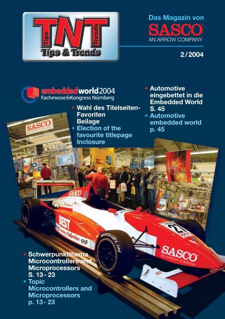
• Schwerpunktthema<br />
Microcontrollers and<br />
Microprocessors<br />
S. 13 - 23<br />
• Topic<br />
Microcontrollers and<br />
Microprocessors<br />
p. 13 - 23<br />
• Wahl des Titelseiten-<br />
Favoriten<br />
Beilage<br />
• Election of the<br />
favourite titlepage<br />
Inclosure<br />
Das Magazin von<br />
2 / 2004<br />
• Automotive<br />
eingebettet in <strong>die</strong><br />
Embedded World<br />
S. 45<br />
• Automotive<br />
embedded world<br />
p. 45
Treffsicher!<br />
Treffsicher und kompetent sollte Ihre Argumentation sein! Wenn auch noch<br />
Teamorientierung zu Ihren Stärken zählt, sollten Sie jetzt weiterlesen:<br />
SASCO gehört <strong>zum</strong> international tätigen ARROW-Konzern, dem weltweit<br />
größten Distributor von elektronischen Bauteilen und Computerprodukten.<br />
Als High-Tech Distributor führender Hersteller konzentrieren wir uns<br />
auf den Markt für elektronische Bauelemente in Zentraleuropa.<br />
Um unseren Demand Creation Fokus weiterhin zu sichern und auszubauen,<br />
suchen wir<br />
Field Application Engineer Microcontroller ( m / w )<br />
für unsere Niederlassungen im gesamten Bundesgebiet<br />
Ihre Aufgabe:<br />
Als technisch kompetenter Ansprechpartner<br />
repräsentieren Sie unser Unternehmen im<br />
Außen<strong>die</strong>nst. Dabei sind Sie in unserem auf<br />
High End Microcontroller und -prozessoren<br />
spezialisierten Support Team verantwortlich<br />
für <strong>die</strong> Identifizierung und Entwicklung neuer<br />
Projekte bei unseren Kunden.<br />
Ihr sicheres Auftreten kommt Ihnen dabei<br />
ebenso zugute wie <strong>die</strong> Teamarbeit mit<br />
unseren Vertriebsmitarbeitern.<br />
Haben wir Ihr Interesse geweckt?<br />
Ihr Profil:<br />
Idealerweise können Sie ein abgeschlossenes<br />
Studium der Elektrotechnik (oder eine<br />
vergleichbare Ausbildung) und einige Jahre<br />
Erfahrung in der Entwicklung vorweisen. Dabei<br />
haben Sie sich fun<strong>die</strong>rte Kenntnisse über<br />
hochintegrierte Microcontroller (z.B. ARM -<br />
oder Renesas SH - Architektur),<br />
Entwicklungswerkzeuge sowie Hochsprachen<br />
und Betriebssystemen angeeignet.<br />
Besonders wichtig ist uns auch Ihre ausgeprägte<br />
Kommunikationsfähigkeit, Ihr<br />
kundenorientiertes Handeln und Bereitschaft<br />
zur Reisetätigkeit.<br />
Wir bieten Ihnen eine vielseitige und interessante Aufgabe in einem international tätigen Unternehmen,<br />
ein leistungsorientiertes Gehalt sowie zahlreiche Zusatzleistungen. Weitere Informationen<br />
erhalten Sie telefonisch von Herrn Klaus Maier unter 0 89 / 46 11 - 2 64 oder im Internet:<br />
www.sasco.de<br />
Nutzen Sie jetzt Ihre Chance<br />
in einer dynamischen<br />
Zukunftsbranche:<br />
Wir freuen uns auf Ihre<br />
aussagekräftige Bewerbung!<br />
SASCO GmbH<br />
Personalabteilung<br />
Wernher - von - Braun - Str. 9a,<br />
D - 85640 Putzbrunn
Editorial<br />
Seht Ihr den Mond dort stehen ...<br />
Do you see the moon standing there ...<br />
„Der weltweite Halbleiterumsatz<br />
erreichte im April<br />
sein höchstes Niveau seit<br />
Juli 2000“; „Zahl der KFZ-<br />
Zulassungen im Juni so<br />
stark gestiegen wie zuletzt<br />
vor vier Jahren“; „Starke<br />
Nachfrage nach Handys<br />
Hauptantriebskraft für Umsatzsteigerung<br />
mit Halbleitern“;<br />
„Hersteller, <strong>die</strong><br />
sich in der Vergangenheit<br />
ausschließlich auf <strong>die</strong><br />
Wachstumsmärkte Data/<br />
Telekom konzentrierten<br />
erkennen den Automobilmarkt<br />
heute <strong>als</strong> stabile<br />
Wachstumschance“ ...<br />
Wenn ich so <strong>die</strong> Wirtschaftsmeldungen<br />
der<br />
letzten Monate lese, fällt<br />
mir das Lied „Der Mond<br />
ist aufgegangen“ ein. Dort<br />
heißt es: „seht Ihr den<br />
Mond dort stehen, er ist<br />
nur halb zu sehen und ist<br />
doch rund und schön, so<br />
geht‘s mit vielen Sachen<br />
<strong>die</strong> wir getrost belachen<br />
weil uns‘re Augen sie<br />
nicht seh‘n“. Oft fehlt uns<br />
der Blick auf <strong>die</strong> globalen<br />
Zusammenhänge, so dass<br />
eine Bewertung der Realität<br />
in zunehmendem<br />
Maße schwer wird. Wir<br />
müssen uns mit steigenden<br />
Lieferzeiten befassen,<br />
<strong>die</strong> aber in ganz anderen<br />
Regionen unserer Welt begründet<br />
sind.<br />
Wir sind gezwungen über<br />
längere Arbeitszeiten, eine<br />
Kürzung der Feiertage und<br />
neue Möglichkeiten der<br />
Alterssicherung nachzudenken.<br />
Zusätzlich sorgt<br />
das politische Umfeld für<br />
Verunsicherung und<br />
wachstumshemmende<br />
Kaufzurückhaltung. Und<br />
das soll uns voran bringen?<br />
Ich meine eher dass<br />
wir auch noch den Rest<br />
des sichtbaren Mondes<br />
verdecken statt uns auf<br />
das Licht zu konzentrieren,<br />
das ihn <strong>zum</strong> Leuchten<br />
bringt.<br />
Wir glauben, dass es viele<br />
positive Informationen gibt,<br />
<strong>die</strong> wir Ihnen näher bringen<br />
sollten. Wir haben <strong>die</strong><br />
neuesten Technologien mit<br />
den Bedürfnissen unserer<br />
Kunden verglichen und<br />
den höchsten Innovations-<br />
grad berücksichtigt. Wir<br />
haben für <strong>die</strong> Verfügbarkeit<br />
<strong>die</strong>ser Produkte gesorgt,<br />
und unsere FAEs bestens<br />
geschult. Wir sind aktiv<br />
und stehen Ihnen mit Rat<br />
und Tat zur Seite. Unser<br />
Know-How ist unsere gemeinsame<br />
Zukunft. Lassen<br />
Sie uns gemeinsam an<br />
<strong>die</strong>ser besseren Zukunft<br />
arbeiten!<br />
Ihr<br />
Michael J. Knappmann<br />
INHALT / CONTENTS<br />
Programmable Logic .......................................................... 4-9<br />
Sensors .......................................................................... 10-12<br />
Microcontrollers and Microprocessors...........................13-23<br />
DSP and Multimedia....................................................... 24-26<br />
Analog ................................................................................. 27<br />
“In April the global<br />
semiconductor turnover<br />
reached the highest<br />
level since July 2000”;<br />
“Number of car registrations<br />
increased in July as<br />
much as last four years<br />
ago”; “Strong demand for<br />
mobile phones is prime<br />
mover for increased<br />
business with semiconductors”;<br />
“Suppliers that<br />
have exclusively concentrated<br />
on the growing<br />
Data / Telecom market now<br />
realize the Automotive<br />
market as chance for<br />
stable growth”... When I<br />
read the business messages,<br />
I remember the<br />
German children song “Der<br />
Mond ist aufgegangen”<br />
(“The moon has risen”),<br />
where it reads “ Do you<br />
see the moon standing<br />
there? There is only half<br />
of it to see, and yet it is<br />
round, and fair! So it is with<br />
many things that we mock<br />
confidently, because our<br />
eyes see them not“ Often<br />
we lack a view for global<br />
cohesions, so that it gets<br />
more and more difficult to<br />
evaluate our realities. We<br />
have to deal with increasing<br />
lead-times which are<br />
caused in total different<br />
regions of the world. We<br />
are forced to think about<br />
longer working hours, cutting<br />
of bank holidays and<br />
new means of retirement<br />
provisions. In addition,<br />
the political environment<br />
causes uncertainties and<br />
growth-inhibiting consumer<br />
resistance. And this<br />
should bring us forward?<br />
I’d rather say that we are<br />
even covering the remainings<br />
of the visible moon,<br />
instead of concentrating<br />
on the light which makes it<br />
gloom.<br />
We think that there is a lot<br />
of positive information we<br />
want to share with you.<br />
We compared the newest<br />
technologies with the<br />
demands of our customers<br />
and took into consideration<br />
the highest degree of<br />
innovation. We have made<br />
sure that these products<br />
are available and that our<br />
FAEs are well trained. We<br />
are active and will support<br />
you in both word and<br />
deed. Our know-how is<br />
our common future. Let<br />
us forge this better future<br />
together!<br />
Your<br />
Michael J. Knappmann<br />
Communication and Interface........................................28-30<br />
Application Briefs .......................................................... 31-38<br />
SASCO Information & News...........................................39-48<br />
Quiz / Information Request via Fax ................................. 50-51<br />
Tips & Trends Page 3<br />
Michael J. Knappmann
Programmable Logic<br />
MAX ® II - das günstigste CPLD<br />
überhaupt !<br />
Mit den MAX Produkten<br />
dominiert ALTERA seit<br />
Jahren den CPLD Markt.<br />
Um <strong>die</strong>s auch in Zukunft<br />
sicherzustellen und den<br />
wachsenden Anforderungen<br />
des Marktes an<br />
Preis, Stromaufnahme,<br />
Leistung und Komplexität<br />
gerecht zu werden, wurde<br />
<strong>die</strong> Meßlatte für <strong>die</strong> neue<br />
Generation von MAX<br />
CPLDs sehr hoch gesteckt.<br />
Mit einer traditionellen<br />
CPLD-Architektur sind<br />
<strong>die</strong> genannten Ziele nicht<br />
zu erreichen. ALTERA<br />
war <strong>als</strong>o gezwungen, mit<br />
MAX II neue, innovative<br />
Wege zu gehen. Gute<br />
Ideen haben häufig eines<br />
gemeinsam: sie sind auch<br />
sehr einfach. MAX II ist<br />
<strong>die</strong> Integration von FPGA<br />
basierten Logik-Strukturen<br />
und bewährter 0,18 µm<br />
Flash Technologie.<br />
In Kombination mit<br />
Features, <strong>die</strong> im CPLD<br />
Bereich bisher noch nicht<br />
zur Verfügung standen,<br />
und kostengünstigen<br />
Gehäusen, entstand eine<br />
strikt Kostenoptimierte<br />
Lösung, das „lowest-cost<br />
CPLD ever“.<br />
Welche Merkmale kennzeichnen<br />
ein CPLD? Diese<br />
Frage wird seit der Ankündigung<br />
der MAX II CPLD<br />
Familie von ALTERA wieder<br />
öfter diskutiert. Generell<br />
wird vorausgesetzt, dass<br />
ein CPLD ein „instant on“<br />
Verhalten zeigt, das heißt<br />
sofort nach Einschalten<br />
seine programmierte<br />
Funktion erfüllt, und<br />
<strong>die</strong>se Programmierung<br />
auch im spannungslosen<br />
Zustand, <strong>als</strong>o „non<br />
volatile“, beibehält. Beide<br />
Anforderungen erfüllt<br />
MAX II voll und ganz.<br />
Im Zentrum der MAX II<br />
Architektur finden sich <strong>die</strong><br />
klassischen Bestandteile<br />
der erfolgreichen Cyclone<br />
FPGAs. Diese Implementierung<br />
erlaubt eine kostengünstige<br />
Fertigung von<br />
MAX II Derivaten, welche<br />
über 2000 Register<br />
bieten und damit deutlich<br />
komplexer sind <strong>als</strong> alle<br />
bisher verfügbaren CPLDs.<br />
Darüber hinaus verdoppelt<br />
<strong>die</strong> neue Architektur<br />
<strong>die</strong> Systemleistung und<br />
verbessert das Fitting-<br />
Verhalten signifikant.<br />
Die Durchlaufzeiten<br />
(Tpd) ergeben für MAX II<br />
branchenübliche Werte von<br />
4,5 – 6,5 ns.<br />
Als Gehäuse werden für<br />
MAX II 100 - pin TQFP<br />
(EPM 240, EPM 570),<br />
MAX ® II - the lowest Cost CPLD<br />
ever !<br />
With its MAX product<br />
family, ALTERA has dominated<br />
the CPLD market<br />
for years. In order to<br />
safeguard this market<br />
leadership and to satisfy<br />
the growing customer<br />
demand regarding price,<br />
power consumption, performance<br />
and complexity,<br />
the go<strong>als</strong> are even higher<br />
for the new generation of<br />
MAX CPLDs.<br />
With a traditional CPLD<br />
approach these ambitious<br />
go<strong>als</strong> would, however, be<br />
out of reach. So ALTERA<br />
was forced to go new<br />
and innovative ways with<br />
MAX II. Good ideas often<br />
have one thing in common,<br />
they are easy, too. MAX II<br />
is the integration of FPGA<br />
based logic structures and<br />
renowned 0.18 µm flash<br />
technology.<br />
In combination with<br />
groundbreaking new<br />
features in the CPLD<br />
market and cost effective<br />
packages, a strictly cost<br />
optimized solution has<br />
been developed: the<br />
“lowest-cost CPLD ever”<br />
What characterizes a<br />
CPLD? This question is<br />
discussed more often<br />
again after the MAX II<br />
CPLD family has been<br />
announced. In general the<br />
customer expects a CPLD<br />
to work immediately after<br />
power-up, the so called<br />
“instant on” capability and<br />
to provide “non volatile”<br />
program storage. Both<br />
requirements are completely<br />
fulfilled by MAX II.<br />
The core of the MAX II<br />
architecture consists<br />
of classic ingre<strong>die</strong>nts<br />
of ALTERA’s popular<br />
Cyclone FPGA family. This<br />
implementation allows<br />
cost-effective production<br />
of MAX II CPLDs that offer<br />
more than 2000 registers<br />
and are thus more complex<br />
than any other CPLD<br />
product available on the<br />
market.<br />
Moreover, ALTERA was<br />
able to double the internal<br />
system performance<br />
and can now provide<br />
significantly improved<br />
fitting capabilities by using<br />
this new architecture. The<br />
propagation delays (Tpd)<br />
are within the typical range<br />
from 4.5 – 6.5 ns.<br />
100 - pin TQFP (EPM 240,<br />
EPM 570), 144 - pin TQFP<br />
(EPM 570,EPM 1270)<br />
256 - pin FBGA<br />
EPM 570,EPM 1270,<br />
EPM 2210), and 324 - pin
Programmable Logic<br />
144 - Pin TQFP (EPM 570,<br />
EPM 1270) 256 - Pin FBGA<br />
(EPM 570, EPM 1270,<br />
EPM 2210) und 324 - Pin<br />
FBGA (EPM 2210) zur<br />
Verfügung stehen. Bei<br />
Bedarf sind auch bleifreie<br />
Varianten bestellbar.<br />
Bisher waren <strong>die</strong> Preise<br />
im CPLD-Markt durch<br />
Produktterm-basierte<br />
Logik geprägt. Hier bringt<br />
<strong>die</strong> MAX II Familie eine<br />
deutliche Preissenkung.<br />
Bei einer Abnahme<br />
von 10.000 Stück pro<br />
Jahr prognostiziert<br />
ALTERA ab Anfang 2005<br />
Preise von US$ 2,95,-<br />
(EPM 240 T 100 C 5)<br />
und US$ 4,40,-<br />
(EPM 570 T 100 C 5). Die<br />
komplexeren Derivate<br />
werden in Preis und Komplexität<br />
gegen Gate-Arrays<br />
und ASICs positioniert.<br />
MAX II CPLDs sind über<br />
eine JTAG Schnittstelle In-<br />
System programmierbar<br />
(ISP). Das Configuration<br />
Flash Memory (CFM),<br />
der eigentliche Träger der<br />
<strong>Design</strong>-Informationen,<br />
konfiguriert beim Power-<br />
Up <strong>die</strong> interne Logik<br />
des Bausteins. Dieser<br />
Vorgang ist je nach<br />
Bausteinkomplexität<br />
in 100 - 300 µs<br />
abgeschlossen, eine<br />
für komplexe CPLDs<br />
übliche Initialisierungszeit.<br />
Natürlich lässt sich das<br />
<strong>Design</strong> über ein Security-<br />
Bit gegen Auslesen<br />
schützen.<br />
Mehr noch, mit Real Time<br />
ISP kann der Baustein im<br />
Betrieb re-programmiert<br />
werden, ohne dabei <strong>die</strong><br />
laufende Funktion des Bausteins<br />
zu beinträchtigen.<br />
Der neu implementierte<br />
JTAG-Translator erlaubt<br />
den direkten Zugriff von<br />
interner Logik auf das<br />
JTAG Interface. Damit<br />
kann u.a. der Test und<br />
<strong>die</strong> Programmierung von<br />
nicht JTAG kompatiblen<br />
Systemkomponenten<br />
auf der Platine deutlich<br />
vereinfacht werden.<br />
Ein Teilbereich des integrierten<br />
Flash Speichers<br />
<strong>steht</strong> dem Anwender <strong>als</strong><br />
8192 Bit großes User<br />
Flash Memory (UFM) zur<br />
Verfügung. Neben JTAG<br />
Programmierung bietet<br />
ALTERA auch SPI und<br />
Paralleles Interface zur<br />
Kommunikation mit dem<br />
UFM an. Damit integriert<br />
MAX II erstm<strong>als</strong> <strong>die</strong> Funktion<br />
von kleinen EEPROMs<br />
und seriellen FLASH-<br />
Speichern in ein CPLD.<br />
Weitere Reduktion der<br />
Systemkosten sind durch<br />
den in MAX II integrierten<br />
FBGA (EPM 2210) package<br />
options will be available.<br />
On request lead-free<br />
package variants can be<br />
ordered.<br />
Until today the prices in<br />
the CPLD market have<br />
been driven by productterm<br />
based products.<br />
MAX II will bring a<br />
significant price reduction<br />
in this segment. ALTERA<br />
predicts prices of US$ 2.95<br />
(EPM 240 T 100 C 5)<br />
and US$ 4.40<br />
(EPM 570 T 100 C 5) for<br />
a demand of 10,000<br />
pieces per year as off<br />
Q1/2005. The more<br />
complex derivatives will<br />
be positioned against<br />
Gate-Arrays and ASICs<br />
regarding price and<br />
complexity.<br />
MAX II is In-System-<br />
Programmable (ISP)<br />
by using the standard<br />
JTAG interface. During<br />
power-up the device is<br />
configured out of the<br />
CFM (Configuration<br />
Flash Memory), which is<br />
the “design memory” of<br />
the device. This leads to<br />
initialization times between<br />
100 - 300 µsec, depending<br />
on the complexity of the<br />
device. A common range<br />
for complex CPLDs. The<br />
design can be secured<br />
by using a programmable<br />
security bit.<br />
This new concept even<br />
allows re-programming<br />
MAX II in Real Time ISP<br />
mode, without interfering<br />
with the current user<br />
configuration.<br />
In addition, the new JTAG<br />
Translator allows internal<br />
logic to access the JTAG<br />
interface directly. This<br />
can be used to simplify<br />
on-board testing and<br />
programming of “non-<br />
JTAG” devices.<br />
One part of the integrated<br />
flash memory can be<br />
accessed as 8192 bit User<br />
Flash Memory (UFM). The<br />
code in the UFM can be<br />
programmed externally via<br />
JTAG or out of the logic<br />
itself by using the SPI or<br />
parallel interfaces provided<br />
by ALTERA. MAX II is the<br />
first product integrating the<br />
functionality of EEPROMs<br />
and serial FLASH in a<br />
CPLD.<br />
An additional reduction<br />
in system costs can be<br />
expected from the onboard<br />
voltage regulator<br />
in MAX II, which allows<br />
source voltage levels from<br />
3.3 V and 2.5 V down to<br />
1.8 V, the original core<br />
voltage. MAX II supports<br />
the I/O standards LVTTL<br />
and LVCMOS. In addition,<br />
Tips & Trends Page 5
Programmable Logic<br />
Spannungsregler zu erwarten,<br />
der Versorgungs spannungen<br />
von 3,3 V und<br />
2,5 V und <strong>die</strong> eigentliche<br />
Core-Versorgung von 1,8 V<br />
erlaubt. Im I/O Bereich unterstützt<br />
MAX II <strong>die</strong> Standards<br />
LVTTL und LVCMOS.<br />
Die I/O-Zelle bietet außerdem<br />
Schmitt-Trigger Eingänge,<br />
Begrenzung der<br />
Flankensteilheit (Slew-<br />
Rate), einstellbare Stromstärke<br />
der Ausgangs treiber<br />
und eine „Output-Enable“<br />
(OE)-Ansteuerung pro Pin.<br />
Sie bietet damit deutlich<br />
mehr Flexibilität <strong>als</strong><br />
bisherige CPLDs.<br />
Die Versorgungsspannung<br />
der I/Os kann zwischen<br />
1,5 V und 3,3 V variiert<br />
wer den und ist je nach<br />
Bausteinkomplexität auf<br />
zwei oder vier I/O-Bänken<br />
frei wählbar. Die Derivate<br />
EPM 1270 und EPM 2210<br />
sind auch für PCI Applikationen<br />
ausgelegt und<br />
erlauben den kostengünstigen<br />
Einsatz <strong>als</strong><br />
PCI Bridge. Der Ersatz<br />
von dis kreten 32-Bit<br />
PCI Lösungen ist damit<br />
möglich.<br />
Ein weiteres Schlüsselelement<br />
von MAX II ist <strong>die</strong><br />
geringe Leistungsaufnahme.<br />
Kombiniert man<br />
den kleinen Ruhestrom von<br />
ca. 2 mA mit der äußerst<br />
geringen dynamischen<br />
Leistungsaufnahme,<br />
ergeben sich im Betrieb<br />
Werte, <strong>die</strong> unter denen<br />
der Wettbewerbsprodukte<br />
liegen.<br />
Damit sind auch batteriebe<br />
triebene Handheld-<br />
Appli kationen mit MAX II<br />
realisierbar.<br />
Ab August 2004 sind erste<br />
Muster des EPM 1270<br />
zu erwarten. Bis Anfang<br />
2005 sind alle Derivate in<br />
Produktionsstückzahlen<br />
geplant. Ein MAX II Low-<br />
Cost Entwicklungs-Kit<br />
ist für September 2004 in<br />
Vorbereitung. Software-<br />
Support für MAX II<br />
inklusive Programmierung<br />
ist seit der Version 4.0 SP1<br />
der Quartus II Software<br />
und der kostenlosen<br />
Webedition gegeben.<br />
Neben dem industriellen<br />
Temperaturbereich (- 40 °C<br />
bis + 85 °C) sind in naher<br />
Zukunft auch Derivate für<br />
erweiterte Temperaturen<br />
(- 40 °C bis + 125 °C)<br />
geplant.<br />
the I/O cell offers Schmitt-<br />
Trigger capabilities as well<br />
as programmable slew rate<br />
control, selectable current<br />
drive strength and one<br />
Output Enable (OE) control<br />
logic per pin. This offers<br />
the user more flexibility<br />
than any other previous<br />
CPLD generation.<br />
The I/O voltage can<br />
be selected in a range<br />
between 1.5 V and 3.3 V<br />
spread among two or four<br />
I/O banks based on device<br />
complexity. EP 1270 and<br />
EPM 2210 devices have<br />
been designed for PCI<br />
applications. This enables<br />
these MAX II devices to<br />
work as low cost PCI<br />
bridges and allows the<br />
replacement of discrete<br />
32 bit PCI solutions.<br />
Another key element<br />
of MAX II is reduced<br />
power consumption.<br />
The standby current of<br />
2 mA, together with a low<br />
dynamical power, results<br />
in very low overall power<br />
consumption compared<br />
to the competition. This<br />
makes MAX II suitable <strong>als</strong>o<br />
for handheld applications.<br />
First samples of the<br />
EPM 1270 are expected<br />
for August 2004. Volume<br />
production quantities for<br />
all products are planned<br />
for the first quarter of<br />
2005. A low-cost MAX II<br />
Development Kit is<br />
scheduled for September.<br />
Software support for<br />
MAX II including pin-out<br />
and programming support<br />
has been available since<br />
Version V4.0SP1 of<br />
Quartus II and the no-cost<br />
Webedition.<br />
MAX II devices will be<br />
available in industrial<br />
temperature ranges (- 40 °C<br />
to + 85 °C). Extended<br />
temperature versions<br />
(- 40 °C bis + 125 °C) are<br />
expected after production<br />
ramp up.<br />
Information: 02/04/01
Programmable Logic<br />
Nios ® II - ALTERAs zweite<br />
Generation des Soft Embedded<br />
Prozessors: Schneller, Kleiner,<br />
Günstiger !<br />
Der Nios Prozessor ist mit<br />
über 13.000 Installationen<br />
der erfolgreichste<br />
SoftCore-IP Prozessor in<br />
der Halbleiter-Industrie und<br />
wird in den unterschiedlichsten<br />
Applikationen<br />
und Markt segmenten<br />
ein gesetzt. Durch seine<br />
Flexibilität und <strong>die</strong><br />
Integration in neueste<br />
FPGA-Architekturen<br />
wächst <strong>die</strong> Zahl der<br />
Anwender <strong>die</strong>ses 32-Bit<br />
RISC Cores weiter stark<br />
an. Damit steigen aber<br />
auch <strong>die</strong> Anforderungen<br />
an Systemleistung,<br />
Ressourcenbedarf,<br />
Kostenstruktur und <strong>die</strong><br />
Software-Tools <strong>die</strong>ser<br />
Prozessor-Lösung.<br />
Für <strong>die</strong> zweite Generation<br />
des Nios Prozessors<br />
wurden deshalb deutliche<br />
Verbesserungen in CPU-<br />
Architektur, Systemleistung<br />
und Logik-Elementebedarf<br />
angestrebt, neue Peripherie-Elemente<br />
integriert und<br />
vor allem <strong>die</strong> Software-<br />
Entwicklung grundlegend<br />
vereinfacht. Resultat sind<br />
drei Grundkonfigurationen<br />
des Nios II:<br />
• Nios II/f (FAST) – Core<br />
optimiert auf System<br />
Performance<br />
• Nios II/s (STANDARD) –<br />
Core mit ausgewogener<br />
Performance und<br />
geringem Logik-Bedarf<br />
• Nios II/e (ECONOMY)<br />
– Core optimiert auf<br />
kleinstmöglichen Logik-<br />
Bedarf<br />
Alle drei RISC-CPU<br />
Cores haben ein 32-Bit<br />
Instruction Set und sind<br />
im Binärcode kompatibel.<br />
Für <strong>die</strong> FAST Konfiguration<br />
strebt ALTERA über 200<br />
Dhrystone MIPS (DMIPS)<br />
in der neuen 90nm<br />
Stratix II Familie an.<br />
Frei wählbar ist auch<br />
<strong>die</strong> Komplexität der<br />
integrierten JTAG Debug-<br />
Hardware. Die Anzahl<br />
der Custom Instructions<br />
ist auf 256 unabhängige<br />
Funktionen gestiegen,<br />
<strong>die</strong> auch in ihrem<br />
Funktionsumfang erweitert<br />
wurden. So lassen sich<br />
mit Custom Instructions<br />
rechenintensive Bestandteile<br />
der Software in FPGA-<br />
Hardware auslagern und<br />
Co-Prozessoren sehr<br />
einfach realisieren, <strong>die</strong> den<br />
Datendurchsatz erheblich<br />
beschleunigen. Ebenfalls<br />
in der Geschwindigkeit<br />
gesteigert wurde <strong>die</strong><br />
Interrupt-Verarbeitung<br />
<strong>die</strong>ser NIOS Generation.<br />
Nios ® II - ALTERA’s second generation<br />
embedded soft processor:<br />
faster, smaller, lower cost !<br />
Nios is the most successful<br />
SoftCore IP processor<br />
in the semiconductor<br />
industry. With more than<br />
13.000 installations it is<br />
used in many applications<br />
and multiple different<br />
market segments alike.<br />
Based on its flexibility<br />
and integration into latest<br />
FPGA architectures,<br />
this 32 bit RISC Core<br />
was adopted very fast<br />
by designers all over<br />
the world. And the<br />
demand is still rising!<br />
But together with this<br />
growing acceptance, the<br />
requirements regarding<br />
performance, resource<br />
usage, cost structure and<br />
the software design tools<br />
are rising, too.<br />
These requirements have<br />
been the foundation for<br />
the second generation of<br />
Nios, providing significant<br />
improvements in CPU<br />
architecture, size and<br />
performance, re-designed<br />
peripher<strong>als</strong> and last but not<br />
least a greatly enhanced<br />
software development<br />
flow.<br />
As a result, Nios II provides<br />
three base configurations:<br />
• Nios II/f (FAST) – Core<br />
optimized for system<br />
performance<br />
• Nios II/s (STANDARD) –<br />
Core balanced between<br />
performance and logic<br />
element usage<br />
• Nios II/e (ECONOMY)<br />
– Core optimized for<br />
smallest possible FPGA-<br />
Footprint<br />
All three RISC-CPU cores<br />
have a 32 bit Instruction<br />
Set and are binary code<br />
compatible. Regarding<br />
FAST configuration it<br />
is ALTERA‘s goal, to<br />
achieve more than 200<br />
Dhrystone-MIPS (DMIPS)<br />
with the 90nm STRATIX II<br />
architecture. The<br />
integrated debug solution<br />
can be parameterized<br />
in size and functionality.<br />
The number of custom<br />
instructions has been<br />
increased to 256 independent<br />
functions. By<br />
using custom instructions<br />
the user can outsource<br />
time consuming software<br />
routines to FPGA hardware.<br />
This makes it easy<br />
to build co-processors for<br />
higher data throughput.<br />
In addition the interrupt<br />
processing speed of Nios II<br />
has been improved.<br />
Tips & Trends Page 7
Programmable Logic<br />
Die Liste der Nios<br />
Standard-Peripherie<br />
wurde um eine JTAG<br />
UART, das im Leistungsumfang<br />
deutlich erweiterte<br />
Common-Flash Interface<br />
und ein SYSTEM-ID<br />
Modul erweitert. Memory-<br />
Management-Unit (MMU)<br />
und Floating Point Unit<br />
(FPU) stehen ebenfalls auf<br />
der Roadmap von ALTERA.<br />
Bis Jahresende soll <strong>die</strong><br />
Liste der Nios-kompatiblen<br />
Peripherie mehr <strong>als</strong> 100 IP-<br />
Cores von ALTERA und<br />
Partnerfirmen beinhalten.<br />
An oberster Stelle der<br />
Wunschliste aller Nios-<br />
User stand eine grafische<br />
Entwicklungsumgebung<br />
zur Software-Entwicklung.<br />
Mit Nios II erfüllt sich<br />
<strong>die</strong>ser Wunsch der Nios-<br />
Gemeinde. Die neue<br />
Entwicklungsumgebung<br />
NIOS TM II Integrated<br />
Development Environment<br />
(IDE) basiert auf ECLIPSE,<br />
einer frei verfügbaren,<br />
robusten Entwicklungsumgebung,<br />
<strong>die</strong> sich<br />
allgemeiner Beliebtheit<br />
erfreut.<br />
The list of available<br />
standard peripher<strong>als</strong><br />
delivered with Nios now<br />
includes a JTAG UART, an<br />
enhanced Common Flash<br />
Interface and a SYSTEM-<br />
ID module. Memory-<br />
Management-Unit (MMU)<br />
and Floating-Point-Unit<br />
(FPU) can be found on the<br />
ALTERA Roadmap. The<br />
number of Nios compatible<br />
peripher<strong>als</strong> provided by<br />
partner companies and<br />
ALTERA is expected to<br />
grow above 100 IP cores<br />
by the end of the year.<br />
Highest priority on the<br />
wants list of nearly all Nios<br />
users was a graphical<br />
design environment to<br />
improve the software<br />
development flow. With<br />
Nios II this wish of the Nios<br />
community will become<br />
true. The new Nios II IDE<br />
(Integrated Development<br />
Environment) is based on<br />
ECLIPSE, a free, robust<br />
and widely accepted<br />
integrated design<br />
environment.
Programmable Logic<br />
Neben der direkten Unterstützung<br />
von embedded<br />
Betriebssystemen wurde<br />
auch ein Instruction Set<br />
Simulator (ISS) in <strong>die</strong>se<br />
neue <strong>Design</strong>-Umgebung<br />
integriert, der Debugging<br />
ohne angeschlossene<br />
Hardware erlaubt. Ein<br />
Hardware-Abstraction-<br />
Layer (HAL) Konzept<br />
ver einfacht <strong>die</strong> Kommunikation<br />
mit den Treibern der<br />
Peripherie.<br />
Über den Support der<br />
NEWLIB Bibliothek wird<br />
<strong>die</strong> Implementierung der<br />
Nios Software Routinen<br />
nach ANSI-C ermöglicht.<br />
Nach dem Kompilerlauf<br />
ist ein Software-<strong>Download</strong><br />
und -Debugging im<br />
Zielsystem direkt über <strong>die</strong><br />
IDE-Oberfläche möglich.<br />
Zusammen mit Nios II<br />
wird der Source Code des<br />
microC/OS-II Betriebssystems<br />
und der neue<br />
Lightweight TCP/IP Stack<br />
ausgeliefert. Weitere ver -<br />
fügbare Betriebssyste me<br />
des Nios II sind u.a. µC-<br />
LINUX (Microtronix),<br />
Nucleus plus (ATI), KROS<br />
und MISPO.<br />
Eine komplette LINUX<br />
Portierung wird nach<br />
Verfügbarkeit der<br />
Memory-Management-<br />
Unit im 4. Quartal 2004<br />
erwartet. Zusätzliche<br />
Betriebssysteme sind in<br />
Vorbereitung.<br />
Flexibilität und Portierbarkeit<br />
waren neben der<br />
„nicht Abkündbarkeit“<br />
schon immer Vorteile<br />
eines Nios Systems. Mit<br />
der jetzt verfügbaren<br />
zweiten Generation<br />
des Nios-Prozessors<br />
dringt ALTERA in neue<br />
Regionen des Preis-<br />
Leistungsverhältnisses<br />
für FPGA-basierte CPUs<br />
vor und bietet mit <strong>die</strong>ser<br />
Lösung nun endgültig auch<br />
einen Ersatz für diskrete<br />
Prozessoren.<br />
In Kürze wird Sie Sasco<br />
mit einer Seminar-Reihe<br />
über <strong>die</strong>sen Embedded<br />
Softcore eingehend<br />
informieren. Details zu<br />
<strong>die</strong>sen Seminaren erhalten<br />
Sie unter www.sasco.de<br />
The Nios IDE directly<br />
supports embedded<br />
operating systems. An<br />
integrated Instruction-<br />
Set-Simulator (ISS) allows<br />
debugging the software<br />
without connection to a<br />
hardware system. The<br />
new Hardware Abstraction<br />
Layer (HAL) concept<br />
makes it much easier<br />
now to communicate with<br />
peripheral drivers.<br />
Based on the NEWLIB<br />
library compliance, it is<br />
now possible to implement<br />
Nios routines in ANSI-C<br />
code. After compilation<br />
the software can be<br />
downloaded to start the<br />
debug process directly<br />
from within the IDE.<br />
Nios II will come with the<br />
source code of the microC/<br />
OS-II operating system<br />
and a lightweight TCP/IP<br />
Stack. Other available<br />
RTOS products are<br />
µC-LINUX (Microtronix),<br />
NucleusPlus (ATI), KROS,<br />
MISPO and others. A<br />
complete LINUX port<br />
is expected after the<br />
availability of the MMU<br />
peripheral. Further<br />
operating systems are<br />
under consideration.<br />
Flexibility, portability<br />
and “none obsolence”<br />
have always been the<br />
advantages of a Nios<br />
based system. With the<br />
availability of the second<br />
generation Nios processor,<br />
ALTERA reaches new<br />
price/performance regions<br />
for FPGA-based CPUs and<br />
is now prepared to offer<br />
this solution even as an<br />
replacement for discrete<br />
processors.<br />
In the near future Sasco<br />
will organize seminars<br />
about Nios II and related<br />
topics. More information,<br />
seminar dates & locations<br />
will be available on the<br />
SASCO homepage<br />
www.sasco.de soon<br />
Tips & Trends Page 9<br />
Information: 02/04/02
Sensors<br />
Vergleichen und sehen Sie selbst -<br />
Low- und Medium-Power<br />
Gate-Drive-Optokoppler<br />
Agilent Technologies bietet<br />
so viele verschiedene<br />
Gate-Drive Optokoppler,<br />
dass es manchmal ziemlich<br />
schwer fällt, das passende<br />
Produkt für eine<br />
Cross - Referenz - Liste<br />
TLP 251 im Vergleich <strong>zum</strong><br />
HCPL - 3020 / 0302<br />
HCPL - 3020 schlägt sein<br />
Gegenstück von Toshiba<br />
bei jeder Spezifikation.<br />
TLP 250 im Vergleich zur<br />
HCPL - 314 Familie oder<br />
<strong>zum</strong> HCPL - T 250<br />
Die HCPL - 314 Familie ist<br />
bei fast jeder Spezifikation<br />
überlegen, lediglich<br />
der Ausgangsstrom<br />
ist geringfügig niedriger.<br />
Beim HCPL - T 250<br />
handelt es sich um ein<br />
sehr ähnliches Produkt,<br />
auch hinsichtlich des<br />
Ausgangsstroms. Die typische<br />
Ausgangsspannung<br />
ist etwas niedriger, was<br />
aber selbst bei Re-<strong>Design</strong>s<br />
keine Schwierigkeit darstellen<br />
dürfte.<br />
TLP 351 im Vergleich zur<br />
HCPL - 314 Familie oder<br />
<strong>zum</strong> HCPL - 3020 / 0302<br />
Auf den ersten Blick<br />
scheint der TLP 351 dem<br />
Applikation herauszufiltern.<br />
Wenn man nun auch noch<br />
Wettbewerbsprodukte,<br />
meist von Toshiba, mit<br />
in Betracht zieht, wird es<br />
sogar noch schwieriger.<br />
Wettbewerbs-Bauteil Agilent Artikelbezeichnung<br />
Toshiba TLP 251 HCPL - 3020 / HCPL - 0302<br />
Toshiba TLP 250 HCPL - 3140 / HCPL - 0314<br />
oder HCPL - T 250<br />
Toshiba TLP 351 HCPL - 3140 / HCPL - 0314 oder<br />
HCPL - 3020 / HCPL - 0302<br />
HCPL - 3140 sehr ähnlich<br />
zu sein, aber auf den zweiten<br />
Blick werden einige interessante<br />
Unterschiede<br />
deutlich: Schon in den<br />
empfohlenen und maximalen<br />
Betriebsverhältnissen<br />
für den TLP 351 zeigen<br />
sich enorme Unterschiede.<br />
Darüber hinaus werden<br />
alle Spezifikationen nur<br />
für 25 °C angegeben, wohingegen<br />
Agilent <strong>die</strong> im<br />
Datenblatt angebebenen<br />
Werte über den gesamten<br />
Temperaturbereich garantiert.<br />
Betrachtet man <strong>die</strong><br />
empfohlenen Betriebsverhältnisse<br />
für den<br />
TLP 351 kommt auch der<br />
HCPL - 3020 <strong>als</strong> Ersatz in<br />
Frage. Zwar sind einige<br />
Spezifikationen des<br />
TLP 351 vielleicht etwas<br />
besser, aber auch hier<br />
wurden <strong>die</strong> Werte nur für<br />
eine Temperatur von 25 °C<br />
und nicht über den gesamten<br />
Temperaturbereich angegeben.<br />
Compare and find out –<br />
Low and medium power gate drive<br />
optocouplers<br />
Agilent Technologies<br />
provides a broad range of<br />
gate drive optocouplers.<br />
The variety of products<br />
makes it sometimes<br />
difficult to address<br />
Cross reference list<br />
TLP 251 versus<br />
HCPL - 3020 / 0302<br />
HCPL - 3020 beats the<br />
Toshiba counterpart in<br />
every relevant datasheet<br />
specification.<br />
TLP 250 versus<br />
HCPL - 314 family or<br />
HCPL - T 250<br />
HCPL - 314 family is<br />
superior in nearly each<br />
specification but the<br />
output current capability<br />
is lower. HCPL - T250 is<br />
a very similar part <strong>als</strong>o<br />
with respect to the output<br />
current. The typical output<br />
voltage is slightly lower<br />
which, however, should<br />
not be a problem, not even<br />
regarding re-designs.<br />
TLP 351 versus<br />
HCPL - 314 family or the<br />
HCPL - 3020 / 0302<br />
On first look the TLP 351<br />
is a close equivalent to<br />
the HCPL - 3140, but<br />
second look reve<strong>als</strong> some<br />
opportunities with the best<br />
matching part. It becomes<br />
even more complicated<br />
when competitive parts,<br />
mainly from Toshiba, are<br />
involved.<br />
Competition part Agilent part number<br />
Toshiba TLP 251 HCPL - 3020 / HCPL - 0302<br />
Toshiba TLP 250 HCPL - 3140 / HCPL - 0314 or<br />
HCPL - T 250<br />
Toshiba TLP 351 HCPL - 3140 / HCPL - 0314 or<br />
HCPL - 3020 / HCPL - 0302<br />
interesting differentiators:<br />
Recommended and<br />
maximum operating<br />
conditions of the<br />
TLP 351 itself show<br />
huge differences. Also<br />
all specifications are<br />
only given for 25 °C<br />
while Agilent guarantees<br />
datasheet performance<br />
across temperature.<br />
Considering the<br />
recommended operating<br />
conditions of the TLP 351,<br />
the HCPL - 3020 is a<br />
suitable replacement, too.<br />
Some specifications of the<br />
TLP 351 might be slightly<br />
better but again only valid<br />
for 25 °C and not across<br />
temperature.
Sensors<br />
Hauptunterschiede<br />
Specification Agilent HCPL-3020 Toshiba TLP251<br />
Isolation voltage according to UL 3570Vrms (1 minute) 2500Vrms (1 minute)<br />
Operating Temperature -40°C up to 100 °C -20°C up to 85°C<br />
Supply Voltage Range 10V – 30V 10V – 20V (70°C)/30V (85°C)<br />
High/Low Level Output Current IOH/IOL Min 0.2A (PW=10µs, Duty Cycle 20%) Min 0.1A<br />
Low Level Output Voltage Typ VEE+0.4 Max VEE+1 Typ VEE+0.5 Max VEE+2.5<br />
Propagation Delay tPHL/tPLH Typ 0.2µs Max 0.7µs Typ 0.25µs Max 1µs<br />
Common Mode Rejection (CMH/CML) Min 10 kV/µs Min 5 kV/µs<br />
Specification Agilent HCPL-3140 Toshiba TLP351<br />
Isolation voltage according to UL 3570Vrms (1 minute) 3570Vrms (1 minute)<br />
High/Low Level Output Current IOH/IOL Min 0.4A Typ 0.5 Min 0.4A Typ 0.63/0,67A (*)<br />
(PW=10µs, Duty Cycle 20%)<br />
High Level Output Voltage Min Vcc-4 Typ Vcc-1.8 Min Vcc-4 Typ Vcc-1.5<br />
at Vcc=15V (*)<br />
High Level Output Current ICCH Typ 0.7mA Max 3mA Typ 1.4mA Max 2mA (*)<br />
Low Level Output Current ICCL Typ 1.2mA Max 3mA Typ 1.2mA Max 2mA (*)<br />
(*) Specified for ambient temperature TA=25°C<br />
Key differentiators<br />
Specification Agilent HCPL-3020 Toshiba TLP351<br />
Isolation voltage according to UL 3570Vrms (1 minute) 3750Vrms (1 minute)<br />
Recommended High/Low Level Min 0.2A (PW=10µs, Duty Cycle 20%) Min 0.2A (**) Typ 0.63/0,67A (*)<br />
Output Current IOH/IOL<br />
High Level Output Voltage Min Vcc-4 Typ Vcc-1.8 Min Vcc-4 Typ Vcc-1.5<br />
at Vcc=15V (*)<br />
High Level Output Current ICCH Typ 0.7mA Max 3mA Typ 1.4mA Max 2mA (*)<br />
Low Level Output Current ICCL Typ 1.2mA Max 3mA Typ 1.3mA Max 2mA (*)<br />
Propagation Delay tPHL/tPLH Typ 0.2µs Max 0.7µs Typ 0.1µs Typ.-Max 0.7µs<br />
(*) Specified for ambient temperature TA=25°C (**) Recommended peak current output<br />
Tips & Trends Page 11
Sensors<br />
Specification Agilent HCPL-3140 Toshiba TLP250<br />
Isolation voltage according to UL 3570Vrms (1 minute) 2500Vrms (1 minute)<br />
Operating Temperature -40°C up to 100 °C -20°C up to 70°C/85°C<br />
Supply Voltage Range 10V – 30V 10V – 24V (85°C)/30V (70°C)<br />
Output Voltage Range 10V – 30V 10V – 24V (85°C)/30V (70°C)<br />
High/Low Level Output Current IOH/IOL Min 0.4A Typ 0.5 Min 0.5A Typ 1.5/2A<br />
(PW=10µs, Duty Cycle 20%)<br />
High Level Output Voltage Min Vcc-4 Typ Vcc-1.8 Min Vcc-4 Typ Vcc-2.2<br />
Low Level Output Voltage Typ 0.4V Max 1V Typ 0.8V Max 2.5V<br />
High Level Output Current ICCH Typ 0.7mA Max 3mA Typ 7mA Max 11mA<br />
Low Level Output Current ICCL Typ 1.2mA Max 3mA Typ 7.5mA Max 11mA<br />
Propagation Delay tPHL Typ 0.2µs Max 0.7µs Typ 0.15µs Max 0.5µs<br />
Propagation Delay tPLH Typ 0.3µs Max 0.7µs Typ 0.15µs Max 0.5µs<br />
Common Mode Rejection (CMH/CML) Min 10 kV/µs Min 5 kV/µs<br />
Specification Agilent HCPL-T250 Toshiba TLP250<br />
Isolation voltage according to UL 3570Vrms (1 minute) 2500Vrms (1 minute)<br />
Operating Temperature -20°C up to 85 °C -20°C up to 70°C (30V)/85°C (20V)<br />
Supply Voltage Range 10V – 30V 10V – 24V (85°C)/30V (70°C)<br />
Output Voltage Range 10V – 30V 10V – 24V (85°C)/30V (70°C)<br />
High/Low Level Output Current IOH/IOL Min 0.5A Typ 1.5/2A Min 0.5A Typ 1.5/2A<br />
High Level Output Voltage Min Vcc-4 Typ Vcc-3 Min Vcc-4 Typ Vcc-2.2<br />
Propagation Delay tPHL Typ 0.27µs Max 0.5µs Typ 0.15µs Max 0.5µs<br />
Propagation Delay tPLH Typ 0.3µs Max 0.5µs Typ 0.15µs Max 0.5µs<br />
Information: 02/04/03
Microcontrollers and Microprocessors<br />
<strong>Design</strong>-Lösungen für<br />
Motorsteuerungen<br />
Microchip Technology<br />
bietet eine umfassende<br />
Produktpalette mit kompletten<br />
Systemlösungen für<br />
verschiedene Motortypen.<br />
Fortschrittliche On-chip<br />
Peripherie<br />
Spezielle Familien der<br />
PIC 8 - Bit Microcontroller<br />
(MCUs) und der digitalen<br />
dsPIC 16 - Bit<br />
Signalcontroller (DSCs) von<br />
Microchip bieten On-chip<br />
Peripherie zur Entwicklung<br />
von leistungsstarken<br />
Präzisionssystemen für <strong>die</strong><br />
Motorsteuerung, <strong>die</strong> das<br />
System nicht nur energiesparender<br />
sondern auch<br />
leiser machen und darüber<br />
hinaus einen breiteren<br />
Funktionsumfang und<br />
lange Lebensdauer bieten.<br />
• High-speed 10 - Bit<br />
Analog-Digital-Konverter<br />
(bis zu 500 Ksps Betrieb)<br />
• Daten-EEPROM (bis zu<br />
4 Kbytes)<br />
• Spezielles<br />
Motorsteuerungs-PWM,<br />
bis zu acht Kanäle und<br />
vier Generatoren mit<br />
flexiblen Betriebsmodi.<br />
• Bis zu acht Enhanced<br />
Capture, Compare,<br />
PWM (ECCP) Module<br />
• Quadratur-Encoder<br />
(Interface oder Input<br />
Captures)<br />
Umfassende technische<br />
Quellen für <strong>die</strong><br />
Entwicklung von<br />
Motorsteuerungen<br />
Alle Ressourcen von<br />
Microchip <strong>zum</strong> Thema<br />
Entwicklung von<br />
Motorsteuerungen<br />
finden Sie im Motor<br />
Control <strong>Design</strong> Center<br />
auf der Webseite<br />
www.microchip.com/<br />
motor.<br />
Graphische<br />
Benutzeroberfläche<br />
„Motor Control“ (GUI)<br />
Mit der graphischen<br />
Benutzeroberfläche<br />
können Benutzer den<br />
Motor und eine Vielzahl<br />
von Systemparametern<br />
für einen ausgewählten<br />
Motor-Typ konfigurieren.<br />
Zu den konfigurierbaren<br />
Parametern zählen<br />
Geschwindigkeit,<br />
Drehrichtung, Stromstärke,<br />
Kühltemperatur,<br />
Fehlerstatus und vieles<br />
mehr. Diese auf Windows ®<br />
-basierende Software<br />
Motor control design solutions<br />
Microchip Technology<br />
offers a broad product<br />
portfolio that provides a<br />
complete system solution<br />
for different types of<br />
motors.<br />
Advanced on-chip<br />
peripher<strong>als</strong><br />
Microchip offers dedicated<br />
families of PIC 8 - bit<br />
microcontrollers (MCUs)<br />
and dsPIC 16 - bit digital<br />
signal controllers (DSCs)<br />
that provide on-chip<br />
peripher<strong>als</strong> to design highperformance<br />
precision<br />
motor control systems that<br />
are more energy efficient,<br />
quieter in operation, have<br />
greater range and an<br />
extended life:<br />
• High-speed 10 - bit<br />
analog-to-digital<br />
converter (up to<br />
500 ksps operation)<br />
• High-endurance<br />
data EEPROM (up to<br />
4 Kbytes)<br />
• Specialized motor<br />
control PWM, up to<br />
eight channels and four<br />
duty cycle generators<br />
with flexible modes of<br />
operation<br />
• Up to eight Enhanced<br />
Capture, Compare, PWM<br />
(ECCP) modules<br />
• Quadrature Encoder<br />
(Interface or Input<br />
Captures)<br />
Complete technical<br />
resources for motor<br />
control design<br />
For access to Microchip’s<br />
complete motor control<br />
design resources,<br />
visit the Motor Control<br />
<strong>Design</strong> Center at<br />
www.microchip.com/<br />
motor.<br />
Motor control graphical<br />
user interface (GUI)<br />
The MC-GUI graphical<br />
user interface allows<br />
users to configure the<br />
motor and a wide range<br />
of system parameters<br />
for a selected motor<br />
type, including speed,<br />
rotation direction, current,<br />
heatsink temperature,<br />
fault status and much<br />
more. Available at no cost,<br />
this Windows ® based<br />
software program supports<br />
Microchip’s motor control<br />
demonstration boards<br />
to provide a complete<br />
solution that helps reduce<br />
design time.<br />
Tips & Trends Page 13
Microcontrollers and Microprocessors<br />
ist kostenlos erhältlich<br />
und unterstützt <strong>die</strong><br />
Motorsteuerungs-Demo-<br />
Boards von Microchip. Der<br />
Benutzer kann auf eine<br />
Komplettlösung zurückgreifen<br />
und so viel Zeit bei<br />
der Entwicklung sparen.<br />
PICDEM MC<br />
Entwicklungs-Board.<br />
Das PICDEM MC<br />
Entwicklungs-Board<br />
(DM 183011) bietet alles,<br />
was man zur Evaluierung<br />
der High-Performance<br />
PIC 18 FXX 31 8 - Bit<br />
Mikrocontroller braucht.<br />
Das Tool unterstützt<br />
Motoren bis zu 800 Watt<br />
und bietet eine komplette<br />
Isolierung der Stromkreise<br />
von den Steuerkreisen.<br />
Dadurch können der<br />
MPLAB ® In-Circuit<br />
Emulator oder MPLAB In-<br />
Circuit Debugger auch<br />
dann an das Board angeschlossen<br />
werden, wenn<br />
<strong>die</strong>ses mit Starkstrom betrieben<br />
wird.<br />
PICDEM MC<br />
development board.<br />
The PICDEM MC<br />
development board<br />
(DM 183011) gives you<br />
everything you need to<br />
evaluate Microchip’s high<br />
performance PIC 18 F XX31<br />
8 - bit microcontrollers<br />
for motor control design.<br />
Supporting motors up<br />
to 800 Watts, the tool<br />
provides total isolation<br />
between power and control<br />
circuits, enabling users to<br />
plug in the MPLAB ® In-<br />
Circuit Emulator or MPLAB<br />
In-Circuit Debugger to the<br />
board when high power is<br />
connected.<br />
dsPIC30F motor control<br />
development system<br />
This high performance<br />
modular system provides<br />
a method for quick<br />
prototyping and validation<br />
of various motor types. The<br />
tools give you the flexibility<br />
to select the appropriate<br />
power modules to meet<br />
your needs. Start with the<br />
dsPICDEM MC1 Motor<br />
Control Development
Microcontrollers and Microprocessors<br />
dsPIC30F<br />
Entwicklungssystem für<br />
Motorsteuerungen<br />
Dieses leistungsstarke<br />
System ist modular<br />
aufgebaut und ermöglicht<br />
<strong>die</strong> schnelle Prototypen-<br />
Entwicklung und -Freigabe<br />
für verschiedene Arten<br />
von Motoren. Mit <strong>die</strong>sen<br />
Tools können Sie <strong>die</strong><br />
Power-Module auswählen,<br />
<strong>die</strong> für Ihre speziellen<br />
Anforderungen am besten<br />
geeignet sind. Beginnen<br />
Sie mit dem<br />
dsPICDEM MC1 Motor<br />
Control Development<br />
Board (DM 300020) und<br />
komplettieren Sie <strong>die</strong>ses<br />
mit dem passenden Power<br />
Modul und einem Motor,<br />
und schon haben Sie ein<br />
komplettes System:<br />
• dsPICDEM MC1H<br />
3-Phasen High-<br />
Voltage Power Modul<br />
(DM 300021)<br />
• 3-Phasen AC Induction<br />
Motor High-Voltage<br />
Motor (208 / 460 V)<br />
(AC 300021)<br />
• dsPICDEM MC1L<br />
3-Phasen Low-<br />
Voltage Power Modul<br />
(DM 300022)<br />
• 3-Phasen Brushless DC<br />
Low-Voltage Motor (24 V)<br />
(AC 300020)<br />
Application Notes<br />
Stepper Motor<br />
AN 822 - Stepper Motor<br />
Microstepping mit<br />
PIC 18 C 452<br />
AN 906 - Stepper Motor<br />
Steuerung mit dem<br />
PIC 16 F 684<br />
AN 907 - Stepper Motor:<br />
Grundlagen<br />
Gleichstrombürstenmotor<br />
AN 532 - Servo Steuerung<br />
eines Gleichstrommotors<br />
AN 696 - PIC 18 C XXX /<br />
PIC 16 C XXX DC<br />
Servomotor<br />
AN 893 -Bidirektionale<br />
Low-Cost Steuerung von<br />
Gleichstrombürstenmotore<br />
n mit dem PIC 16 F 684<br />
AN 905 - Gleichstrombürstenmotor<br />
Grundlagen<br />
Wechselstrom-<br />
Induktionsmotor<br />
AN 843 – Regelung der<br />
Geschwindigkeit bei einem<br />
Drehstrommotor mit einem<br />
PIC 18 Mikrocontroller<br />
AN 861 - Smart Air Handler<br />
unter Verwendung von<br />
ProMPT und dem<br />
PIC 18 F 2539<br />
AN 887 – Wechselstrom-<br />
Induktionsmotor:<br />
Grundlagen<br />
AN 889 - VF Steuerung bei<br />
einem Drehstrommotor<br />
mit Hilfe des PIC 16 F 7X7<br />
Mikrocontrollers<br />
AN 900 - VF Steuerung bei<br />
einem Drehstrommotor mit<br />
Hilfe des PIC 18 F 4431<br />
Board (DM 300020) and<br />
add the appropriate power<br />
module and motor for a<br />
complete system:<br />
• dsPICDEM MC1H<br />
3-Phase High-Voltage<br />
Power Module<br />
(DM 300021)<br />
• 3-Phase AC Induction<br />
Motor High-Voltage<br />
Motor (208 / 460 V)<br />
(AC 300021)<br />
• dsPICDEM MC1L<br />
3-Phase Low-Voltage<br />
Power Module<br />
(DM 300022)<br />
• 3-Phase Brushless DC<br />
Low-Voltage Motor (24 V)<br />
(AC 300020)<br />
Application notes<br />
Stepper motor<br />
AN 822 - Stepper Motor<br />
Microstepping with<br />
PIC 18 C 452<br />
AN 906 - Stepper Motor<br />
Control Using the<br />
PIC 16 F 684<br />
AN 907 - Stepper Motor<br />
Fundament<strong>als</strong><br />
Brushed DC motor<br />
AN 532 - Servo Control of<br />
a DC Brush Motor<br />
AN 696 - PIC 18 C XXX/<br />
PIC 16 C XXX DC<br />
Servomotor<br />
AN 893 - Low-cost<br />
Bidirectional Brushed DC<br />
Motor Control Using the<br />
PIC 16 F 684<br />
AN 905 - Brushed DC<br />
Motor Fundament<strong>als</strong><br />
AC induction motor<br />
AN 843 - Speed Control<br />
of a 3-Phase Induction<br />
Motor Using PIC 18<br />
Microcontrollers<br />
AN 861 - Smart Air Handler<br />
Using ProMPT and<br />
PIC 18 F 2539<br />
AN 887 - AC Induction<br />
Motor Fundament<strong>als</strong><br />
AN 889 - VF Control<br />
of 3-Phase Induction<br />
Motors Using PIC 16 F 7X7<br />
Microcontrollers<br />
AN 900 - VF Control of<br />
3-phase AC Induction<br />
Motors Using the<br />
PIC 18 F 4431<br />
AN 908 - Using the<br />
dsPIC30F for Vector<br />
Control of an AC Induction<br />
Motor<br />
Variable speed brushless<br />
DC Motor<br />
AN 857 - Brushless DC<br />
Motor Control Made Easy<br />
AN 885 - Brushless<br />
DC (BLDC) Motor<br />
Fundament<strong>als</strong><br />
AN 899 - Brushless DC<br />
Motor Control Using<br />
PIC 18 F XX31<br />
AN 901 - Using the<br />
dsPIC30F for Sensorless<br />
BLDC Control<br />
Tips & Trends Page 15
Microcontrollers and Microprocessors<br />
AN 908 – Verwendung<br />
des dsPIC 30 F für<br />
<strong>die</strong> Vektor-Steuerung<br />
eines Wechselstrom-<br />
Induktionsmotors<br />
Bürstenloser Variable<br />
Speed Gleichstrommotor<br />
AN 857 – Steuerung<br />
von bürstenlosen<br />
Gleichstrommotoren leicht<br />
gemacht<br />
AN 885 - Bürstenlose<br />
Gleichstrom- (BLDC)<br />
Motoren: Grundlagen<br />
AN 899 – Steuerung<br />
von bürstenlosen<br />
Gleichstrommotoren mit<br />
dem PIC 18 F XX31<br />
SASCO Niederlassungen<br />
SASCO Berlin<br />
Kaiserin-Augusta-Allee 112,<br />
D - 10553 Berlin<br />
Tel.: 0 30 / 34 99 24 - 0<br />
Fax: 0 30 / 34 99 24 - 36<br />
Vertrieb.Berlin@sasco.de<br />
SASCO Dortmund<br />
Hildebrandstraße 11,<br />
D - 44319 Dortmund<br />
Tel.: 02 31 / 91 72 00 - 0<br />
Fax: 02 31 / 91 72 00 - 9 94<br />
Vertrieb.Dortmund@sasco.de<br />
SASCO Frankfurt<br />
Max-Planck-Straße 1-3,<br />
D - 63303 Dreieich<br />
Tel.: 0 61 03 / 93 73 - 0<br />
Fax: 0 61 03 / 93 73 - 1 65<br />
Vertrieb.Frankfurt@sasco.de<br />
SASCO Hamburg<br />
Schnackenburgallee 149 c,<br />
D - 22525 Hamburg<br />
Tel.: 0 40 / 52 87 46 - 0<br />
Fax: 0 40 / 52 87 46 - 22<br />
Vertrieb.Hamburg@sasco.de<br />
AN 901 – Verwendung des<br />
dsPIC 30 F zur Sensorlosen<br />
BLDC Steuerung<br />
Allgemein<br />
AN 894 – Motorsteuerungssensoren<br />
und deren<br />
Rückkopplungsschalter<br />
AN 898 – Anforderungen<br />
an einen MOSFET Treiber<br />
bei Motorsteuerungen<br />
SASCO München<br />
Wernher-von-Braun-Str. 9a,<br />
D - 85640 Putzbrunn<br />
Tel.: 0 89 / 46 11 - 2 11<br />
Fax: 0 89 / 46 11 - 2 71<br />
Vertrieb.Muenchen@sasco.de<br />
SASCO Stuttgart<br />
Höpfigheimer Str. 5,<br />
D - 74321 Bietigheim-Bissingen<br />
Tel.: 0 71 42 / 9 60 - 0<br />
Fax: 0 71 42 / 9 60 - 100<br />
Vertrieb.Stuttgart@sasco.de<br />
SASCO Wien<br />
Landstrasser Hauptstr.<br />
97-101 1/4A,<br />
A - 1030 Wien<br />
Tel.: +43 (0) 1 / 3 60 46 - 61<br />
Fax: +43 (0) 1 / 3 60 46 - 97<br />
Vertrieb.Wien@sasco.de<br />
General<br />
AN 894 - Motor Control<br />
Sensor Feedback Circuits<br />
AN 898 - Determining<br />
MOSFET Driver Needs for<br />
Motor Drive Applications<br />
SASCO offices<br />
SASCO Yverdon<br />
En Chamard 35,<br />
CH - 1440 Montagny p/Yverdon<br />
Tel.: +41 (0) 24 / 4 47 01 00<br />
Fax: +41 (0) 24 / 4 45 52 45<br />
SalesOffice.Yverdon@sasco.de<br />
SASCO Zürich<br />
Riedmatt 9,<br />
CH - 8153 Rümlang<br />
Tel.: +41 (0) 44 / 8 17 62 80<br />
Fax: +41 (0) 44 / 8 17 62 81<br />
Vertrieb.Zuerich@sasco.de<br />
SASCO Brüssel<br />
Keiberg II,<br />
Minervastraat 14/B2,<br />
B - 1930 Zaventem<br />
Tel.: +32 (0) 2 / 7 19 71 - 50<br />
Fax: +32 (0) 2 / 7 09 13 40<br />
SalesOffice.Brussels@sasco.de<br />
SASCO Utrecht<br />
Elzenkade 3,<br />
NL - 3992 AD Houten<br />
Tel.: +31 (0) 30 / 6 39 12 15<br />
Fax: +31 (0)30 / 6 39 12 16<br />
SalesOffice.Utrecht@sasco.de<br />
SASCO Prag<br />
Charkovská 24,<br />
101 00 Praha 10,<br />
Czech Republic<br />
Tel.: +42 (0) 2 / 71 74 20 00<br />
Fax: +42 (0) 2 / 71 74 20 01<br />
SalesOffice.Prague@sasco.de<br />
SASCO Warschau<br />
ul. Sobieskiego 110/28,<br />
00 764 Warszawa,Poland<br />
Tel.: +48 (0) 22 / 8 56 90 90<br />
Fax: +48 (0) 22 / 8 51 61 36<br />
SalesOffice.Warsaw@sasco.de<br />
SASCO Budapest<br />
Váci út 45,<br />
1134 Budapest, Hungary<br />
Tel.: +36 (0) 1 / 32 94 20 02<br />
Fax: +36 (0) 1 / 3 50 62 77<br />
SalesOffice.Budapest@sasco.de<br />
Information: 02/04/04
Microcontrollers and Microprocessors<br />
Super Low-Power Microcontroller<br />
von Renesas<br />
H8 / 38076 F – der<br />
Baustein mit dem geringsten<br />
Stromverbrauch<br />
Renesas stellt das erste<br />
Mitglied der neuen<br />
H8 / 300 H SLP Serie,<br />
den H8 / 38076 F vor. Der<br />
Baustein wurde speziell für<br />
Applikationen mit extrem<br />
niedrigen Stromverbrauch<br />
entwickelt und vereint den<br />
leistungsstarken 16 - Bit<br />
H8 / 300 H Tiny CPU Kern<br />
mit einer Vielzahl von leistungsfähigen<br />
On-Chip<br />
Peripherie-Funktionen und<br />
Low–Voltage Flash On-<br />
Chip. Er verfügt über eine<br />
Reihe von einzigartigen<br />
Low-Power Funktionen<br />
wie schnelles Anlaufen des<br />
Oszillators, RTC, asynchronen<br />
Timer, serielles<br />
Low-Power Interface (1200<br />
Baud bei 10 µA!!) und eine<br />
Betriebsspannung von<br />
Minimum 1,8 V.<br />
Der H8 / 38076 F verfügt<br />
über viele Funktionen, um<br />
<strong>die</strong> Entwicklung unterschiedlicher<br />
Produkte so<br />
einfach wie möglich zu gestalten.<br />
So bietet er unter<br />
anderem einen integrierten<br />
Watchdog Timer mit eigenem<br />
internen RC Oszillator,<br />
einen LCD Controller-<br />
Treiber mit eigenem einstellbaren<br />
Chip-Booster,<br />
der somit eine digitale<br />
Kontrastkontrolle ermöglicht<br />
sowie ein eingebautes<br />
Multi-Master I 2 C-Interface,<br />
ideal um EEPROMs anzuschließen.<br />
Diese Funktionen<br />
machen den H8 / 38076 F<br />
zur perfekten Lösung<br />
für viele batterie-<br />
und netzbetriebenen<br />
Anwendungen wie<br />
beispielsweise<br />
Heizungszähler,<br />
Wasserzähler, netzbetriebene<br />
Modems und intelligente<br />
Sensoren. Bereits<br />
heute stehen Muster und<br />
Entwicklungtools in geringer<br />
Zahl zur Verfügung!<br />
H8 / 38076 F<br />
Spezifikationen<br />
• 10 MHz H8 / 300H CPU<br />
Core<br />
• 1,8 – 3,6 V<br />
Betriebsspannung<br />
• 32 kHz Sub-clock<br />
Betrieb<br />
• 48 KBytes Single supply<br />
Flash<br />
• 24 - 48 KBytes Masken-<br />
ROM<br />
• 1 - 2 KByte RAM<br />
• 2 x SCI Interface ( 1 x<br />
IrDA )<br />
• I 2 C<br />
Renesas super low power<br />
microcontrollers<br />
H8 / 38076 F – the lowest<br />
power consumption solution<br />
Renesas now releases the<br />
first member of the new<br />
H8 / 300 H SLP series,<br />
the H8 / 38076 F. The<br />
component is designed<br />
for extremely low power<br />
applications and combines<br />
the powerful 16-bit<br />
H8 / 300 H Tiny CPU core<br />
with a variety of powerful<br />
on chip peripher<strong>als</strong> and<br />
low voltage on chip flash.<br />
It has a number of low<br />
power features including<br />
fast oscillator start<br />
up, RTC, asynchronous<br />
timer, low power serial<br />
interface (1200 baud<br />
from at 10 µA !!) and an<br />
operating voltage down to<br />
1.8 V.<br />
The H8 / 38076 F includes a<br />
variety of features to make<br />
it as easy as possible to<br />
develop many different<br />
products, including an<br />
integrated watchdog timer<br />
with its own internal RC<br />
oscillator, LCD controller<br />
driver with its own on chip<br />
booster that is tuneable<br />
to allow for digital contrast<br />
control, and a built in<br />
multi-master I 2 C interface,<br />
ideal for interfacing<br />
to EEPROMs and other<br />
peripher<strong>als</strong>.<br />
These features make the<br />
H8 / 38076 F perfect for a<br />
variety of battery and line<br />
powered applications,<br />
such as heat and water<br />
meters, line powered<br />
modems and intelligent<br />
sensors. Samples and<br />
development tools for the<br />
H8 / 38076 F are available<br />
now!<br />
H8 / 38076 F specification<br />
• 10 MHz H8 / 300 H CPU<br />
Core<br />
• 1.8 – 3.6 V operation<br />
• 32 kHz sub-clock<br />
operation<br />
• 48 Kbytes Single supply<br />
Flash<br />
• 24 - 48 kbytes of Mask<br />
ROM<br />
• 1 - 2 kbyte RAM<br />
• 2 x SCI interface ( 1 x<br />
IrDA )<br />
• I 2 C<br />
• 3 x 16-bit timer<br />
• Real Time Clock<br />
• Watchdog timer with<br />
independent oscillator<br />
• 1 x Asynchronous timer<br />
• 2 x 14-bit PWM<br />
• 8 ch 10-bit A/D converter<br />
• 25 x 4 LCD<br />
controller / driver<br />
Tips & Trends Page 17
Microcontrollers and Microprocessors<br />
• 3 x 16-Bit Timer<br />
• Real Time Clock<br />
• Watchdog Timer mit<br />
unabhängigem Oszillator<br />
• 1 x asynchroner Timer<br />
• 2 x 14-Bit PWM<br />
• 8-Kanal 10-Bit A/D-<br />
Wandler<br />
• 25 x 4 LCD-Controller /<br />
-Treiber<br />
• Power-on-Reset<br />
• 80 Pins<br />
Der H8 / 38076 F befindet<br />
sich einem platzsparenden<br />
80-Pin-Gehäuse und wird<br />
vom neuen E7 In-Circuit<br />
Debugger unterstützt.<br />
• Power on reset<br />
• 80 pins<br />
The H8 / 38076 F comes<br />
in a space saving 80 pin<br />
package and is supported<br />
by the new E7 in-circuit<br />
debugger.<br />
H8 SLP Selektor H8 SLP Selector<br />
Schnellreferenz: Super Low Power 80-Pin Serie Super low power 80-pin series quick reference
Microcontrollers and Microprocessors<br />
Schnellreferenz: Super Low Power 64-Pin Serie<br />
H8/38076 Referenz – Bestellinformation<br />
Product Flash Memory RAM Package<br />
Mask ROM QFP-80A TQFP-80C P-TFLGA-85<br />
( FP-80A ) (TFP-80C ) ( TLP-85V )<br />
H8/38076F 48 kbytes - 2 kbyte HD64F38076H HD64F38076W HD64F38076LPV<br />
H8/38076 - 48 kbytes 2 kbyte HD64338076H HD64338076W HD64338076LPV<br />
H8/38075 - 40 kbytes 2 kbyte HD64338075H HD64338075W HD64338075LPV<br />
H8/38074 - 32 kbytes 1 kbyte HD64338074H HD64338074W HD64338074LPV<br />
H8/38073 - 24 kbytes 1 kbyte HD64338073H HD64338073W HD64338073LPV<br />
H8/38086 Referenz – Bestellinformation<br />
Super low power 64-pin series quick reference<br />
H8/38076 reference – ordering information<br />
H8/38086 reference – ordering information<br />
Product Flash Memory RAM Package<br />
Mask ROM QFP-80A TQFP-80C P-TFLGA-85<br />
( FP-80A ) (TFP-80C ) ( TLP-85V )<br />
H8/38086F 48 kbytes - 2 kbyte HD64F38086H HD64F38086W HD64F38086LPV<br />
H8/38086 - 48 kbytes 2 kbyte HD64338086H HD64338086W HD64338086LPV<br />
H8/38085 - 40 kbytes 2 kbyte HD64338085H HD64338085W HD64338085LPV<br />
H8/38084 - 32 kbytes 1 kbyte HD64338084H HD64338084W HD64338084LPV<br />
H8/38083 - 24 kbytes 1 kbyte HD64338083H HD64338083W HD64338083LPV<br />
Tips & Trends Page 19<br />
Information: 02/04/05
Microcontrollers and Microprocessors<br />
Sharp BlueStreak: ARM ® Microcontroller<br />
für unterschiedlichste<br />
Entwicklungen.<br />
Wählen Sie <strong>die</strong> Leistung,<br />
<strong>die</strong> Sie benötigen:<br />
Die BlueStreak<br />
ARM 7 / ARM 9<br />
Microcontroller zählen<br />
zu den vielseitigsten<br />
Bauteilgruppen mit<br />
dem höchsten Grad<br />
an Integration. Diese<br />
Produktfamilie wird in<br />
den unterschiedlichsten<br />
Marktsegmenten eingesetzt<br />
und hat vor kurzem<br />
auch den Frost & Sullivan<br />
Product Innovation Award<br />
für 2004 erhalten.<br />
Mit Microcontrollern wie<br />
der ARM 7 TDMI-basierten<br />
LH 754 XX Produktguppe,<br />
<strong>die</strong> über einen externen<br />
16 - Bit Datenbus verfügt,<br />
und einer Reihe<br />
von Microcontrollern<br />
mit externem 32 - Bit<br />
Datenbus, bietet Sharp<br />
alles, was Sie für Ihre<br />
Applikation benötigen. Zur<br />
Produktgruppe mit externem<br />
32 - Bit Datenbus<br />
zählen Bauteile wie der<br />
ARM 720 T - basierte<br />
LH 79520, der ARM 922 T -<br />
basierte LH 7 A 400 und der<br />
LH 7 A 404.<br />
Die meisten der<br />
ARM 7 / ARM 9 Microcontroller<br />
von Sharp bieten<br />
einen überaus flexiblen<br />
On - Chip LCD Controller,<br />
der auch <strong>die</strong> anspruchsvollsten<br />
Display-<br />
Technologien unterstützt.<br />
Darüber hinaus verfügen<br />
<strong>die</strong> Microcontroller<br />
über glueless<br />
Speicherschnittstellen,<br />
serielle High-Speed<br />
Schnittstellen wie USB, I 2 S,<br />
SPI, I 2 C, CAN und Ethernet<br />
Controller, Analog/<br />
Digital-Wandler, Touch-<br />
Screen-Controller, herausnehmbare<br />
Speicherkarten<br />
und eine hohe Anzahl von<br />
Standard I/Os. Sharps<br />
neue Generation von High-<br />
End Microcontrollern basiert<br />
auf ARM 946 E und<br />
ARM 926 EJ. Sie sind somit<br />
nicht nur leistungsfähi-<br />
ger, sondern bieten darüber<br />
hinaus ein Imager<br />
Interface, einen Media<br />
Accelerator sowie eine erweiterte<br />
Graphics Engine.<br />
Mit den BlueStreak<br />
Microcontrollern treffen<br />
Sie gleich beim ersten<br />
Mal ins Schwarze.<br />
Sharp BlueStreak: ARM ® microcontrollers<br />
spanning a<br />
spectrum of design possibilities.<br />
Choose your power and<br />
performance level:<br />
Sharp’s BlueStreak<br />
ARM 7 / ARM 9 microcontrollers<br />
represent one of<br />
the most versatile, most<br />
integrated device portfolios<br />
available today. The family<br />
addresses a vast range of<br />
market applications, and<br />
have recently be honored<br />
with the Frost & Sullivan<br />
Product Innovation Award<br />
2004.<br />
Sharp answers your application<br />
needs by offering<br />
microcontrollers such as<br />
the ARM 7 TDMI-based<br />
LH 754 XX family, featuring<br />
a 16 - bit external data bus,<br />
as well as microcontrollers<br />
with a full 32 - bit external<br />
data bus; these include the<br />
ARM 720 T-based LH 79520<br />
and ARM 922 T-based<br />
LH 7 A 400 and LH 7 A 404.<br />
Most Sharp ARM 7 /<br />
ARM 9 microcontrollers<br />
include a highly flexible<br />
on-chip LCD controller<br />
supporting leading display<br />
technologies.<br />
Also included are glueless<br />
memory interfaces; highspeed<br />
serial interfaces<br />
including USB, I 2 S, SPI,<br />
I 2 C, CAN, and Ethernet<br />
Controller; analog-todigital<br />
converters; touch<br />
screen controllers;<br />
removable storage cards;<br />
and generous amounts<br />
of GPIO. Sharp’s nextgeneration<br />
high-end<br />
microcontrollers are<br />
based on ARM 946 E and<br />
ARM 926 EJ, enabling<br />
higher performance<br />
coupled with an imager<br />
interface, media accelerator,<br />
and an enhanced<br />
graphics engine.<br />
Sharp BlueStreak microcontrollers<br />
give you the<br />
power to hit your market<br />
opportunity right the first<br />
time.<br />
By working with worldclass<br />
partners to provide a<br />
wide range of ready-made<br />
hardware and software<br />
solutions, Sharp helps you<br />
to save months of development<br />
time and recoup<br />
your investment faster.<br />
Application development<br />
kits for Sharp BlueStreak<br />
microcontrollers
Microcontrollers and Microprocessors<br />
Sharp arbeitet mit<br />
erstklassigen Partnern<br />
wie <strong>zum</strong> Beispiel der<br />
Firma Logic zusammen,<br />
um viele verschiedene<br />
gebrauchsfertige Hard-<br />
und Software-Lösungen<br />
anbieten zu können. Das<br />
spart Ihnen monatelange<br />
Entwicklungsarbeit.<br />
So machen sich Ihre<br />
Investitionen schneller<br />
bezahlt.<br />
Mit den Entwicklungs-<br />
Kits für BlueStreak<br />
Microcontroller können<br />
Sie sofort mit der<br />
Software-Entwicklung<br />
beginnen, und das auf<br />
Plattformen, <strong>die</strong> nahtlos<br />
an <strong>die</strong> Produktion<br />
anknüpfen.<br />
So bieten beispielsweise<br />
<strong>die</strong> Entwicklungs-Kits<br />
der Firma Logic eine<br />
preisgünstige stabile<br />
Plattform, auf der<br />
sofort mit der Software-<br />
Entwicklung begonnen<br />
werden kann. Die<br />
produktionsfertigen Card<br />
Engine Plattformen können<br />
auch zur Unterstützung der<br />
Endfertigung verwendet<br />
werden. Darüber hinaus<br />
beschleunigen stabile<br />
Referenz-<strong>Design</strong>s,<br />
Production Quality Drivers<br />
und Bootloader<br />
<strong>die</strong> Entwicklung.<br />
Durch <strong>die</strong> bekannten<br />
Betriebssysteme wie Linux,<br />
WinCE, ThreadX, VxWorks<br />
and Nucleus+ pre-ported,<br />
können sich Entwickler<br />
anstatt auf <strong>die</strong> Umsetzung<br />
auf Innovationen<br />
konzentrieren.<br />
Kostenlose Software-<br />
<strong>Download</strong>s von<br />
www.sharpmcu.com.<br />
Auf <strong>die</strong>ser Seite stehen<br />
eine Vielzahl von Board<br />
Support Paketen sowie<br />
Referenz-Treiber für<br />
gängige Betriebssysteme<br />
<strong>zum</strong> <strong>Download</strong> bereit.<br />
Außerdem haben Sie<br />
Zugang zu Hunderten<br />
von bewährten Providern<br />
der ARM Connected<br />
Community. Diese<br />
bieten unterschiedlichste<br />
Lösungen, angefangen bei<br />
Compilern, Assemblern<br />
und Debuggern, bis hin<br />
zu Software IP, JTAG<br />
Debuggern und <strong>Design</strong>-<br />
Services.<br />
allow engineers to<br />
immediately begin<br />
software development<br />
on platforms that<br />
transfer seamlessly to<br />
production.<br />
As an example, Logic’s<br />
development kits provide<br />
a low-cost and stable<br />
platform on which to<br />
immediately begin<br />
software development.<br />
Its production-ready Card<br />
Engine platforms can <strong>als</strong>o<br />
be used to support final<br />
production. In addition,<br />
solid reference designs,<br />
production quality drivers<br />
and bootloaders are in<br />
place to accelerate your<br />
development. With popular<br />
operating systems such<br />
as Linux, WinCE, ThreadX,<br />
VxWorks and Nucleus+<br />
pre-ported, designers can<br />
focus on innovation rather<br />
than implementation.<br />
Free software<br />
downloads from<br />
www.sharpmcu.com.<br />
You can download board<br />
support packages and<br />
reference drivers for<br />
popular operating systems.<br />
Plus, you have access<br />
to hundreds of providers<br />
within the ARM Connected<br />
Community offering<br />
solutions ranging from<br />
compilers, assemblers,<br />
and debuggers to software<br />
IP, JTAG debuggers and<br />
design services.<br />
Tips & Trends Page 21<br />
Information: 02/04/06
Microcontrollers and Microprocessors<br />
ADuC 702x – eine hochgenaue<br />
analoge Microcontroller-Familie<br />
mit ARM7 ® Kern<br />
Durch <strong>die</strong> Integration<br />
vieler hochgenauer analoger<br />
Funktionen und eines<br />
digitalen Rechenkerns<br />
auf einem Halbleiterchip<br />
will Analog Devices<br />
Steuerungs-, Regelungs-<br />
und Überwachungs-<br />
Aufgaben in Anwendungen<br />
wie Sensorik für <strong>die</strong> Fertigungsautomatisierung,<br />
Transmitter für optische<br />
Netzwerke und elektronische<br />
Fahrwerksregelungen<br />
bei Fahrzeugen, vereinfachen.<br />
Die Microcontroller-<br />
Lösung be<strong>steht</strong> aus einem<br />
leistungsfähigen 32-Bit-<br />
RISC-Prozessorkern<br />
und einem Präzisions-<br />
Datenwandlerteil, der einen<br />
schnellen 12 Bit genauen<br />
A/D-Wandler für bis<br />
zu 16 analoge Eingangs-<br />
Kanäle und bis zu vier D/A-<br />
Wandler enthält.<br />
Die analoge Microcontroller-Familie<br />
ADuC 702x mit<br />
ARM7-Kern erweitert das<br />
umfangreiche Portfolio an<br />
8052-basierten Lösungen<br />
der MicroConverter ® -Serie.<br />
Die MicroConverter wurden<br />
– wie auch <strong>die</strong> neue<br />
Modellreihe auf ARM7-<br />
Basis – für anspruchsvolle<br />
digital programmierbare<br />
Anwendungen in den<br />
Bereichen Mess- und<br />
Regeltechnik und<br />
Messwerterfassung entwickelt.<br />
Verarbeitungsleistung,<br />
Peripherie und kleine<br />
Gehäuse<br />
Die neue Produktfamilie<br />
ADuC 702x enthält einen<br />
ARM7TDMI ® -Core und<br />
einen 16 / 32-bit-RISC-<br />
Prozessor-Kern mit einer<br />
Spitzen-Verarbeitungsleistung<br />
von 45 MIPS.<br />
Hinzu kommen <strong>die</strong> monolithisch<br />
integrierte analoge<br />
Peripherie in Form von<br />
schnellen 12 - Bit - A/D-<br />
Wandlern mit bis zu 16<br />
Kanälen, vier eigenständige<br />
12 - Bit - D / A - Wandler<br />
und eine hochgenaue<br />
Bandgap-Referenz mit<br />
einer Spannungsdrift von<br />
weniger <strong>als</strong> 10 ppm / °C.<br />
Außerdem wurden<br />
Peripherie-Elemente wie<br />
Komparator, PLA (programmierbare<br />
Logik) sowie<br />
ein Dreiphasen-PWM-<br />
Generator integriert. Die<br />
Bauelemente unterstützen<br />
auch flexible Power-Down-<br />
ADuC702x – highly precise analog<br />
microcontroller family with ARM7 ®<br />
Core<br />
By embedding precision<br />
analog functionality<br />
with digital programming<br />
on a single chip, Analog<br />
Devices aims to greatly<br />
simplify control and<br />
monitoring in applications<br />
such as factory automation<br />
sensors, optical network<br />
transmitters and automotive<br />
body control electronics.<br />
Analog Devices’<br />
precision analog microcontroller<br />
solution integrates<br />
a powerful 32 - bit RISC<br />
core with precision data<br />
conversion technology<br />
that supports up to 16<br />
channels of fast, 12 - bit<br />
accurate analog-to-digital<br />
conversion and up to four<br />
12 - bit digital-to-analog<br />
converters.<br />
The ADuC 702x precision<br />
analog microcontroller<br />
family featuring ARM7based<br />
programmability<br />
joins Analog Devices’<br />
portfolio of 8052-based<br />
solutions, known as the<br />
MicroConverter series.<br />
Like the ARM7 core familybased<br />
range of products,<br />
MicroConverter products<br />
are designed for high-precision<br />
measurement and<br />
control, and data acquisition<br />
systems with basic<br />
digital programming needs.<br />
Processing power,<br />
peripher<strong>als</strong> and tiny<br />
packages<br />
The new ADuC 702x<br />
solutions integrate an<br />
ARM7TDMI ® core that<br />
features a flash-based<br />
16 - / 32 - bit RISC (reduced<br />
instruction set computer)<br />
MCU with processing<br />
capability up to 45 MIPS<br />
peak performance. Analog<br />
peripher<strong>als</strong> include up to<br />
16 channels of fast, 12 - bit<br />
accurate analog-to-digital<br />
conversion, up to four individual<br />
12 - bit monotonic<br />
DACs (digital-to-analog<br />
converters) and a precision<br />
bandgap reference<br />
with a drift performance<br />
of better than 10 ppm / °C.<br />
Other peripher<strong>als</strong> include a<br />
comparator, PLA (programmable<br />
logic array), and<br />
3-phase PWM generator.<br />
The devices <strong>als</strong>o support<br />
flexible power-down and<br />
wake-up modes and are<br />
specified for 3 - V operation<br />
with a temperature<br />
range of – 40 °C to + 85 °C,<br />
+ 105 °C, and + 125 °C.<br />
Packaging options range<br />
from a tiny 6 mm x 6 mm<br />
40 - lead CSP (chip-scale<br />
package) to an 80 pin<br />
LQFP.
Microcontrollers and Microprocessors<br />
und Wake-Up-Modi und<br />
sind für den Betrieb mit<br />
Versorgungsspannungen<br />
von 3 V für den<br />
Temperaturbereich von<br />
- 40 °C bis + 85 °C bzw.<br />
+ 105 °C bzw. + 125 °C spezifiziert.<br />
Das Spektrum der<br />
möglichen Gehäuse reicht<br />
vom winzigen nur 6 mm x<br />
6 mm großen 40 - poligen<br />
CSP (Chip-Scale Package)<br />
bis <strong>zum</strong> 80 - poligen LQFP.<br />
Anwendungen<br />
So profitieren beispielsweise<br />
Geräte zur Fertigungs-<br />
Automatisierung, <strong>die</strong> mit<br />
Ultraschall-, Magnet- oder<br />
optischen Näherungs-<br />
Sensoren ausgerüstet<br />
sind, von der Integration<br />
der Analog-Funktionen<br />
und eines leistungsfähigen<br />
Prozessorkerns in einem<br />
kleinen Gehäuse. Die<br />
Produktfamilie ADuC 702x<br />
bietet eine integrierte<br />
Überwachungs- und<br />
Steuerungs-Lösung für<br />
optische SFP- und XFP-<br />
Transceiver. Da <strong>die</strong> ICs der<br />
ADuC 702x - Familie das<br />
LIN-Protokoll unterstützen,<br />
eignen sie sich auch für<br />
den Einsatz im Bereich der<br />
Fahrwerk- und Komfort-<br />
Elektronik im Automobil.<br />
Zukünftige Derivate mit integriertem<br />
CAN-Controller<br />
und zusätzlichem<br />
Speicher werden weitere<br />
Einsatzmöglichkeiten auf<br />
dem Automotive-Sektor ermöglichen.<br />
Entwicklungswerkzeuge<br />
Das preisgünstige<br />
Entwicklungssystem<br />
QuickStart von Analog<br />
Devices enthält ein umfangreiches<br />
Paket an<br />
Software-Entwicklungs-<br />
Tools von KEIL Software<br />
und IAR Systems. Diese<br />
Software wird zusammen<br />
mit der unterstützenden<br />
Hardware (Evaluation-<br />
Board, JTAG-Emulator,<br />
Stromversorgung, Kabel)<br />
ausgeliefert.<br />
Applications<br />
Factory automation equipment,<br />
utilizing ultrasonic,<br />
magnetic or optical<br />
proximity sensors, benefits<br />
from the integration<br />
of precision analog with a<br />
powerful processing core<br />
in a small package. The<br />
ADuC 702x family offers an<br />
integrated monitoring and<br />
control solution for SFP<br />
and XFP optical transceivers.<br />
By including support<br />
for LIN, the ADuC 702x<br />
family offers solutions for<br />
body-control electronics<br />
in automobiles. To further<br />
support the automotive<br />
market, future derivatives<br />
will integrate CAN and<br />
additional memory.<br />
Development tools<br />
Analog Devices’ low-cost<br />
QuickStart Development<br />
System includes a suite of<br />
comprehensive software<br />
development tools by KEIL<br />
Software and IAR Systems.<br />
These are shipped along<br />
with supporting hardware,<br />
such as evaluation board,<br />
JTAG emulator, power<br />
supply and cables.<br />
Tips & Trends Page 23<br />
Information: 02/04/07
DSP and Multimedia<br />
AVF 49xyA<br />
Audio / Video Front-End<br />
Bei dem AVF 49xyA<br />
handelt es sich um eine<br />
komplett integrierte<br />
Audio-Video Front-End<br />
Lösung, <strong>die</strong> gerade<br />
für DVD-Rekorder und<br />
Personal Video-Rekorder<br />
(PVR) bestens geeignet<br />
ist. Sie verbindet <strong>die</strong><br />
Funktionseinheiten eines<br />
Multistandard Sound<br />
Prozessors (MSP) mit<br />
denen eines Video Pixel<br />
Decoders (VPX) und bietet<br />
darüber hinaus Audio-<br />
/Video-Synchronisierung<br />
des Ausgangssign<strong>als</strong>.<br />
Der AVF 49xyA wird<br />
im PQFP128 Gehäuse<br />
geliefert. Die MSP-Einheit<br />
kann alle weltweit üblichen<br />
analogen TV-Standards<br />
sowie digitale NICAM<br />
Soundstandards verarbeiten.<br />
Die komplette TV-<br />
Sound–Verarbeitung<br />
wird abgedeckt, vom<br />
analogen Sound IF-Signal-<br />
Eingang bis hin <strong>zum</strong><br />
bearbeiteten analogen<br />
AF-Signal-Ausgang.<br />
Die VPX-Einheit bietet<br />
den kompletten Umfang<br />
an Videoaufnahme-<br />
Funktionen für<br />
Consumer- und Multimedia-Anwendungen.<br />
Der Baustein hat alle Verarbeitungsmöglichkeiten<br />
integriert, um ein analoges<br />
Videosignal im CVBS-,<br />
Y/C- oder YcrCb-Format in<br />
einen digitalen Datenstrom<br />
zu konvertieren. Darüber<br />
hinaus bietet er Text Slicing<br />
für Intercast, Teletext, und<br />
Closed Caption. Für eine<br />
bessere Y/C Trennung<br />
<strong>steht</strong> ein adaptiver 4H<br />
Kammfilter zur Verfügung.<br />
AVF 49xyA<br />
Audio / Video Front-end<br />
The AVF 49xyA is a<br />
fully integrated Audio-<br />
Video Front-end solution<br />
specifically well suited for<br />
DVD recorder and personal<br />
video recorder (PVR)<br />
applications. It combines<br />
the functional units of both<br />
a Multistandard Sound<br />
Processor (MSP) and a<br />
Video Pixel Decoder (VPX)<br />
and it provides the audio/<br />
video synchronization of<br />
the output signal. The<br />
AVF 49xyA comes in a<br />
PQFP128 package. The<br />
MSP unit covers the sound<br />
processing of all analog TV<br />
standards worldwide, as<br />
well as the NICAM digital<br />
sound standards. The<br />
full TV sound processing<br />
– starting with analog<br />
sound IF signal input<br />
down to processed analog<br />
AF signal output – is<br />
performed. The VPX unit<br />
provides the full-feature<br />
video acquisition for<br />
consumer and multimedia<br />
applications. All of the<br />
processing capability<br />
necessary to convert<br />
an analog video signal<br />
in CVBS, Y/C or YCrCb<br />
format into a digital<br />
component stream is<br />
integrated. Additionally,<br />
text slicing for Intercast,<br />
Teletext, and Closed<br />
Caption is provided. For<br />
improved Y/C separation,<br />
an adaptive 4H comb filter<br />
is included.
DSP and Multimedia<br />
Allgemeine Funktionen<br />
• I 2 C Schnittstelle<br />
mit verschiedenen<br />
Geräteadressen zur<br />
Nutzung von zwei AVF<br />
49xyA in einem System<br />
• Audio / Video-<br />
Synchronisierung<br />
entweder im Master-<br />
oder im Slave-Modus<br />
• PQFP128-2 Gehäuse<br />
Video-Funktionen<br />
• Leistungsstarker<br />
adaptiver 4H Kammfilter<br />
Y/C Separator mit<br />
einstellbarem Vertikal-<br />
Spitzenwert<br />
• Multistandard Farb-<br />
Deco<strong>die</strong>rung:<br />
– NTSC-M, NTSC-443<br />
– PAL-BDGHI, PAL-M,<br />
PAL-N, PAL-60<br />
– SECAM, S-VHS<br />
• Video ADCs mit<br />
Klemmung und automatischer<br />
Verstär kungssteuerung<br />
(Auto matic<br />
Gain Control - AGC)<br />
• Sieben analoge Eingänge<br />
mit integrierter<br />
Auswahl folgender<br />
Quellen:<br />
– 4x Composite Video<br />
(CVBS), oder<br />
– 2x CVBS und 2x Y/C<br />
(S-VHS), oder<br />
– 2x CVBS, 1x Y/C und<br />
1x YPrPb<br />
• Deco<strong>die</strong>rung und<br />
Erkennung von vollständig<br />
Macrovision 7.01<br />
geschützten Videodaten<br />
• Zuschneiden und skalieren<br />
in zwei Fenstern<br />
• Horizontales Skalieren<br />
zwischen 32 und 864<br />
Pixel/Zeile<br />
• Hochwertiger Anti-<br />
Aliasing Filter<br />
• Skalierungs-gesteuertes<br />
Peaking und Coring<br />
• Digitales YCrCb 4:2:2<br />
Format<br />
• ITU-R 601/656 konformes<br />
Ausgangsformat<br />
• Quadratisches Pixel-<br />
Format (640/768 Pixel/<br />
Zeile)<br />
• Synchroner 8-Bit oder<br />
16-Bit Ausgangsmodus<br />
• 13,5 MHz/16-Bit<br />
und 27 MHz/8-Bit<br />
Ausgangsdatenrate<br />
• VBI Bypass und<br />
unbear beiteter ADC<br />
Datenausgang<br />
• Leistungsstarkes<br />
Hardware Daten-Slicing<br />
• Multistandard Daten-<br />
Slicer<br />
– NABTS, WST<br />
– CAPTION (1x, 2x),<br />
CGMS, VPS, WSS,<br />
Antiope<br />
General features<br />
• I 2 C interface with different<br />
device addresses<br />
for using two AVF 49xyA<br />
in one system<br />
• Audio / video synchronization<br />
either in Master<br />
or Slave mode<br />
• PQFP128-2 package<br />
Video features<br />
• High-performance adaptive<br />
4H comb filter Y/C<br />
separator with adjustable<br />
vertical peaking<br />
• Multistandard color<br />
decoding:<br />
– NTSC-M, NTSC-443<br />
– PAL-BDGHI, PAL-M,<br />
PAL-N, PAL-60<br />
– SECAM, S-VHS<br />
• Video ADCs with<br />
clamping and automatic<br />
gain control (AGC)<br />
• Seven analog inputs with<br />
integrated selector for<br />
the following sources:<br />
– 4x composite video<br />
(CVBS), or<br />
– 2x CVBS and 2x Y/C<br />
(S-VHS), or<br />
– 2x CVBS, 1x Y/C and<br />
1x YPrPb<br />
• Decoding and detection<br />
of full Macrovision 7.01<br />
protected video<br />
• Dual-window cropping<br />
and scaling<br />
• Horizontal resizing<br />
between 32 and 864<br />
pixels/line<br />
• High-quality anti-aliasing<br />
filter<br />
• Scaling controlled<br />
peaking and coring<br />
• Digital YCrCb 4:2:2<br />
format<br />
• ITU-R 601/656 compliant<br />
output format<br />
• Square pixel format<br />
(640/768 pixels/line)<br />
• 8-bit or 16-bit synchronous<br />
output mode<br />
• 13.5 MHz/16-bit and<br />
27MHz/8-bit output rate<br />
• VBI bypass and raw ADC<br />
data output<br />
• High-performance<br />
hardware data slicing<br />
• Multistandard data slicer<br />
– NABTS, WST<br />
– CAPTION (1x , 2x),<br />
CGMS, VPS, WSS,<br />
Antiope<br />
• Full support for<br />
– Teletext, Intercast<br />
– WebTV for Windows,<br />
EPG services<br />
• VBI and Full-field mode<br />
• Data insertion into video<br />
stream<br />
Tips & Trends Page 25
DSP and Multimedia<br />
• Vollständige Unterstützung<br />
von<br />
– Teletext, Intercast<br />
– WebTV für Windows,<br />
EPG Services<br />
• VBI und Full-field Modus<br />
• Dateneinspeisung in<br />
Video-Fluss<br />
• Gleichzeitige Erfassung<br />
von Teletext, VPS, WSS<br />
und Caption<br />
Audio-Funktionen<br />
• Standard-Auswahl<br />
mit nur einer I 2 C-<br />
Übertragung<br />
• Automatische Erkennung<br />
terrestrischer TV-<br />
Standards<br />
• Automatische Sound-<br />
Wahl (mono / stereo /<br />
zweisprachig), neue<br />
Register MODUS,<br />
STATUS<br />
• Sound IF (SIF) Eingang<br />
• Automatic-Carrier-Mute<br />
Funktion<br />
• Programmierbarer<br />
Interrupt Output (zeigt<br />
Statusänderungen)<br />
• Haupt-/AUX-Kanal mit<br />
Lautstärke<br />
• Automatische Lautstärkenkorrektur<br />
(Automatic volume<br />
correction - AVC)<br />
• Zwei-Kanal Mixer<br />
• Wählbare Vorverstärkung<br />
für AUX-Kanal<br />
• Vier Stereo-Eingänge,<br />
zwei Stereo-Ausgänge<br />
• Komplette Line in/out<br />
Schaltmatrix<br />
• Zwei 48-kHz I 2 S Eingänge,<br />
ein asynchroner<br />
5 bis 50kHz I 2 S Eingang,<br />
ein asynchroner I 2 S<br />
Ausgang<br />
• Alle analogen Mono-<br />
Tonträger inklusive AM-<br />
SECAM<br />
• Alle analogen FM-<br />
Stereo A2- und<br />
Satellitenstandards<br />
• Alle NICAM-Standards<br />
• Gleichzeitige Demodulation<br />
von (sehr) stark<br />
abweichenden FM-Mono<br />
und NICAM<br />
• Demodulation des<br />
BTSC-Multiplex-Sign<strong>als</strong><br />
und des SAP-Kan<strong>als</strong><br />
• Abgleich-freie digitale<br />
DBX Rauschsperre für<br />
BTSC Stereo und SAP<br />
• BTSC Stereo- und EIA-J<br />
Trennung bedeutend<br />
besser <strong>als</strong> spezifiziert.<br />
• SAP- und Stereo-<br />
Erkennung für BTSC<br />
• Koreanischer FM-Stereo<br />
A2 Standard<br />
• Abgleich-freier<br />
japanischer Standard<br />
EIA-J<br />
• Demodulation des FM-<br />
Radio-Multiplex-Sign<strong>als</strong><br />
• Simultaneous acquisition<br />
of Teletext, VPS, WSS,<br />
and Caption<br />
Audio Features<br />
• Standard selection with<br />
single I 2 C transmission<br />
• Automatic standard<br />
detection of terrestrial TV<br />
standards<br />
• Automatic sound<br />
selection (mono/stereo/<br />
bilingual), new registers<br />
MODUS, STATUS<br />
• Sound IF (SIF) input<br />
• Automatic-carrier-mute<br />
function<br />
• Interrupt output<br />
programmable<br />
(indicating status<br />
change)<br />
• Main/AUX channel with<br />
volume<br />
• Automatic volume<br />
correction (AVC)<br />
• Two channel mixer<br />
• Selectable pre-emphasis<br />
for AUX channel<br />
• Four stereo line inputs,<br />
two stereo line outputs<br />
• Complete line in/out<br />
switching matrix<br />
• Two 48-kHz I 2 S inputs;<br />
one asynchronous 5 to<br />
50-kHz I 2 S input, one<br />
asynchronous I 2 S output<br />
• All analog Mono sound<br />
carriers including AM-<br />
SECAM<br />
• All analog FM-Stereo A2<br />
and satellite standards<br />
• All NICAM standards<br />
• Simultaneous<br />
demodulation of (very)<br />
high-deviation FM-Mono<br />
and NICAM<br />
• Demodulation of the<br />
BTSC multiplex signal<br />
and the SAP channel<br />
• Alignment-free digital<br />
DBX noise reduction for<br />
BTSC Stereo and SAP<br />
• BTSC Stereo and EIA-J<br />
separation significantly<br />
better than spec.<br />
• SAP and stereo<br />
detection for BTSC<br />
• Korean FM-Stereo A2<br />
standard<br />
• Alignment-free Japanese<br />
standard EIA-J<br />
• Demodulation of the FM-<br />
Radio multiplex signal<br />
Information: 02/04/08
Analog<br />
MICRF 505 – MICRELs neue<br />
Generation „RadioWire ® “ RF<br />
Transceiver<br />
Der neue MICR F 505<br />
Transceiver arbeitet<br />
im Frequenzband von<br />
850 MHz bis 950 MHz und<br />
ermöglicht Datenraten<br />
bis zu 200 kbps in<br />
FSK (Frequency Shift-<br />
Keyed) Modulation. Zum<br />
Betrieb des Transceivers<br />
werden nur wenige externe<br />
Bauteile (ein<br />
paar Kondensatoren,<br />
eine Induktivität) benötigt.<br />
Per <strong>Design</strong> kommt<br />
der MICR F 505 mit relativ<br />
ungenauen Low-<br />
Cost Quarzen aus. So<br />
wurden auf dem Bauteil<br />
Schaltungen integriert, <strong>die</strong><br />
Frequenzabweichungen<br />
zwischen kommunizierenden<br />
Chips feststellen und<br />
automatisch beheben. Eine<br />
interne „Clock Recovery“-<br />
Schaltung wurde ebenfalls<br />
implementiert, was<br />
das Zusammenspiel mit<br />
Low-Cost Microcontrollern<br />
erleichtert. Weitere<br />
Funktionen (z.B. der<br />
Frequenzsynthesizer) sind<br />
programmierbar gestaltet.<br />
Zusammenfassung der<br />
Spezifikationen und<br />
Eigenschaften<br />
• Frequenzband von<br />
850 MHz bis 950 MHz<br />
• - 112 dBm Empfindlichkeit<br />
(2,4 Kbps bei<br />
10 -3 BER)<br />
• Ausgangsleistung<br />
programmierbar bis zu<br />
+ 10 dBm<br />
• 200 kbps maximale<br />
Datenrate<br />
• Versorgungsspannung<br />
2,0 V bis 2,5 V<br />
• Stromverbrauch: 13 mA<br />
im Empfangsmodus,<br />
28 mA im Sendemodus<br />
• Integrierter Sende-/<br />
Empfangsschalter<br />
• Integrierte Clock<br />
Recovery<br />
• Voll programmierbare<br />
PLL<br />
• Digitale Quarzfrequenzjustierung<br />
Zur Entwicklungsunterstützung<br />
gibt es von<br />
MICREL das „MICRFDEV1<br />
Development System“,<br />
sowie Firmware und<br />
Dokumentation. Kostenlos<br />
aus dem Internet erhältlich<br />
ist <strong>die</strong> „MICR F 505 RF Test<br />
Bench“ Software, <strong>die</strong> <strong>die</strong><br />
nötigen Werte der externen<br />
Komponenten, sowie <strong>die</strong><br />
Konfiguration der internen<br />
Register berechnet.<br />
Der MICRF505 ist im<br />
5 mm x 5 mm MLF -<br />
Gehäuse erhältlich und<br />
kostet ca. US$ 4,50 bei<br />
einer Abnahme von 1.000<br />
Stück.<br />
MICRF 505 – MICREL’s new<br />
generation of “RadioWire ® “ RF<br />
transceivers<br />
The MICR F 505 transceiver<br />
operates from 850 MHz to<br />
950 MHz and supports frequency<br />
shift-keyed (FSK)<br />
modulation at data-rates<br />
up to 200 kbps. The transceiver<br />
can operate with<br />
only a few external components<br />
(just a few capacitors,<br />
one inductor). The<br />
MICR F 505 is designed to<br />
accommodate low-cost,<br />
low-accuracy cryst<strong>als</strong>. To<br />
address this, Micrel has<br />
added a frequency error<br />
estimator to determine frequency<br />
mismatch between<br />
communicating transceivers<br />
and an internal crystal<br />
tuning mechanism to<br />
enable automated crys-<br />
tal tuning on-the-fly. The<br />
MICR F 505 <strong>als</strong>o incorporates<br />
an internal clock<br />
recovery circuit to reduce<br />
the burden on its companion<br />
baseband device<br />
enabling the use of a lower<br />
cost microcontroller. Many<br />
functions, including the<br />
frequency synthesizer are<br />
user programmable.<br />
Summary of specifications<br />
and features<br />
• 850 MHz to 950 MHz<br />
operating range<br />
• - 112 dBm sensitivity<br />
(2.4 kbps at 10 -3 BER)<br />
• Output power<br />
programmable to<br />
+10 dBm<br />
• 200 kbps maximum datarate<br />
• Supply voltage from<br />
2.0 V to 2.5 V<br />
• Supply current: 13 mA in<br />
receive mode, 28 mA in<br />
transmit mode<br />
• Integrated T/R switch<br />
• Integrated clock<br />
recovery circuit<br />
• Fully programmable PLL<br />
• Digital crystal trimming<br />
capacity<br />
Development support<br />
is provided by Micrel’s<br />
“MICRFDEV1 Development<br />
System” as well as<br />
firmware and documentation.<br />
The “MICR F 505<br />
RF Test Bench” software<br />
which calculates required<br />
values of the external components<br />
and configurations<br />
of internal registers, can be<br />
downloaded for free from<br />
the Web.<br />
The MICR F 505 ships in<br />
a 5 mm x 5 mm MLF -<br />
package and costs approx.<br />
US$ 4.50 when buying<br />
1.000 pieces.<br />
Tips & Trends Page 27<br />
Information: 02/04/09
Communication and Interface<br />
IDT Flow-Control Management IDT flow-control management<br />
Bausteine für das Flow-<br />
Control Management<br />
sparen Entwicklungszeit<br />
und Systemkosten<br />
für High-Speed<br />
Applikationen, <strong>die</strong><br />
multiple Datenströme<br />
verwenden.<br />
Die Flow-Control<br />
Management Bausteine<br />
führen Data-Flow-Control<br />
und -Management<br />
Aufgaben aus. Sie enthalten<br />
Bausteine für<br />
Multi-Queuing- ,<br />
Multiplexing- und<br />
Sequential Flow-<br />
Applikationen. Dabei ist<br />
jeder Baustein auf gewisse<br />
Funktionen spezialisiert<br />
und bietet <strong>die</strong><br />
optimale Mischung aus<br />
Leistung, Flexibilität,<br />
Benutzerfreundlichkeit und<br />
günstiger Kostenstruktur.<br />
Sie verbinden fortschrittliche<br />
Sequential-<br />
und Random Memory<br />
Technologien von IDT mit<br />
speziellen Logikfunktionen,<br />
wie Memory-Controller,<br />
Multi-Level Queue<br />
Controller, Multiplexer,<br />
Demultiplexer, Packet-<br />
Level Access Controls<br />
und Taktsteuerungen.<br />
Durch <strong>die</strong> Flow-Control<br />
Management Bausteine<br />
müssen <strong>die</strong> kundenspezifischen<br />
Subsysteme nicht<br />
mehr definiert, entwickelt,<br />
modelliert, implementiert,<br />
verifiziert und getestet<br />
werden.<br />
Weil <strong>die</strong> den Flow-Control-<br />
Produkten innewohnende<br />
Logik Steuersignale zu-<br />
sammenlegt, können einfachere<br />
FPGAs oder ASICs<br />
<strong>als</strong> Controller verwendet<br />
werden. Dies wiederum<br />
hilft Kosten sparen.<br />
Figure 1<br />
QuadMux Produkte<br />
Die QuadMux Produkte<br />
von IDT bieten vier unabhängige<br />
Ports auf<br />
einer Seite des Bausteins<br />
und ermöglichen so leistungsstarkes<br />
Datenfluss-<br />
Management. Jeder<br />
<strong>die</strong>ser Ports verfügt über<br />
einen eigenständigen<br />
Datenspeicher und einen<br />
einzelnen Bus zu den anderen<br />
Ports. Dadurch<br />
können <strong>die</strong> Daten zwischen<br />
verschiedenen<br />
Datenströmen wechseln.<br />
Mit <strong>die</strong>sen Flow-Control<br />
Bausteinen verfügen<br />
Flow-control<br />
management devices<br />
save design time and<br />
system cost in highspeed<br />
applications<br />
that have multiple data<br />
streams.<br />
The IDT flow-control<br />
management building<br />
blocks perform data-flow<br />
control and management<br />
functions and comprise<br />
devices for Multi-queuing<br />
, Multiplexing and<br />
Sequential Flow applications.<br />
Each type of<br />
devices are tailored to<br />
deliver specific functions<br />
with optimum balances<br />
of performance, flexibility,<br />
ease-of-use and<br />
cost effectiveness. They<br />
combine advanced IDT<br />
sequential and random<br />
memory technologies with<br />
special logic functions<br />
such as memory controllers,<br />
multi-level queue<br />
controllers, multiplexers,<br />
demultiplexers, packetlevel<br />
access controls and<br />
clock-control circuits. The<br />
IDT flow-control building<br />
blocks eliminate the need<br />
to define, design, model,<br />
implement, verify and<br />
test custom subsystem<br />
designs. The standard<br />
products can <strong>als</strong>o help to<br />
save costs substantially<br />
by simplifying the FPGA<br />
or ASIC used as a controller,<br />
since the logic internal<br />
to Flow Control products<br />
consolidates control<br />
sign<strong>als</strong>.<br />
QuadMux devices<br />
The IDT QuadMux devices<br />
enable high performance<br />
data-flow management by<br />
providing four independent<br />
ports on one side of the<br />
device, each with its own<br />
data memory block, and<br />
a single bus on the other,<br />
thereby allowing data to<br />
flow between multiple data<br />
streams. These flow-control<br />
devices give system<br />
architects an innovative,<br />
beneficial way to implement<br />
both sequential and<br />
random manipulation of<br />
input and output data<br />
using a single, highly integrated<br />
device.<br />
The QuadMux flow-control<br />
devices can be configured<br />
to deliver multiplexing,<br />
de-multiplexing or broadcasting<br />
functionality with<br />
a total bandwidth of up to
Communication and Interface<br />
Entwickler über ein innovatives,vorteilhaftes<br />
Werkzeug, sowohl<br />
für <strong>die</strong> sequentielle wie<br />
auch für <strong>die</strong> zufallsbedingte<br />
Beeinflussung<br />
von Eingangs- und<br />
Ausgangsdaten.<br />
Die QuadMux Flow-<br />
Control Bausteine können<br />
so konfiguriert werden,<br />
dass sie verschiedene<br />
Funktionalitäten<br />
wie Multiplexing,<br />
Demultiplexing oder<br />
Senden mit einer<br />
Bandbreite von bis zu<br />
16 Gbps Double Data<br />
Rate (DDR) ausführen.<br />
Sie sind somit <strong>die</strong><br />
ideale Lösung für viele<br />
Kommunikationsanwendungen,<br />
<strong>die</strong> Datenstrom-<br />
Konvergenz und parallele<br />
Pufferung verschiedener<br />
Datenpfade benötigen.<br />
Dazu zählen beispielsweise<br />
Terabit Router und<br />
Switches, Applikationen<br />
zur Datenerfassung und<br />
Bildbearbeitung sowie<br />
Base-Station-Routing<br />
Systeme.<br />
QuadMux Anwendung:<br />
Parallele Verarbeitung<br />
Die neuen Single-Chip<br />
QuadMux Flow-Control-<br />
Bausteine von IDT können<br />
herkömmliche und teurere<br />
Methoden <strong>zum</strong><br />
Multiplexing multipler<br />
Datenströme bei verschiedenen<br />
Datenraten ersetzen.<br />
So überwachen <strong>zum</strong><br />
Beispiel in der Applikation<br />
in Bild 1 mehrere Datenerfassungsgeräteverschiedene<br />
Vorgänge, wie<br />
Blutdruck, Herzfrequenz,<br />
Atemfrequenz und<br />
Sauerstoffgehalt. Jede<br />
Datenerfassungseinheit<br />
kann Daten in unterschiedlichen<br />
Abständen an den<br />
QuadMux melden. An<br />
dessen einzigem Ausgang<br />
verarbeitet ein digitaler<br />
Signalprozessor (DSP) <strong>die</strong><br />
Daten, <strong>die</strong> hereinkommen,<br />
konstant und unabhängig<br />
vom Dateneingang.<br />
Früher hätte <strong>die</strong>se Art der<br />
parallelen Verarbeitung<br />
wahrscheinlich einen<br />
Multiplexer und verschiedene<br />
ASICs, FPGAs oder<br />
eine Kombination aus<br />
Standardlogik und FIFOs<br />
benötigt.<br />
Figure 2<br />
Multi-Queue Produkte<br />
IDTs Multi-Queue Familie<br />
bietet Flow-Control ICs<br />
mit Single Data Rate (SDR)<br />
oder Double Data Rate<br />
(DDR). Diese Produkte<br />
eignen sich bestens für<br />
Applikationen, <strong>die</strong> Quality<br />
of Service (QoS), Daten-<br />
Differenzierung und<br />
Pufferung verschiedener<br />
virtueller Datenströme fordern.<br />
Dazu zählen beispielsweise<br />
Terabit Router,<br />
Multi-Service Switching<br />
Plattformen und schnurlose<br />
Basisstationen. Eine<br />
Multi-Queue Einheit kann<br />
einen Datenstrom in bis<br />
zu 32 einzelne Queues<br />
aufteilen, von denen wiederum<br />
jede verschiedene<br />
Prioritäten oder Qualities of<br />
16 Gbps Double Data Rate<br />
(DDR). They are ideal solutions<br />
for many communications<br />
applications where<br />
data-stream convergence<br />
and parallel buffering of<br />
multiple data paths are<br />
required, such as terabit<br />
routers and switches, data<br />
acquisition and imaging<br />
applications, and base station<br />
routing systems.<br />
QuadMux application:<br />
Parallel processing<br />
The new IDT single-chip<br />
QuadMux flow-control<br />
devices can replace<br />
traditional and more<br />
costly methods of muxing<br />
multiple data streams at<br />
different data rates. For<br />
example, in the application<br />
in figure 1, multiple data<br />
acquisition devices are<br />
simultaneously monitoring<br />
events such as medical<br />
blood pressure, heart<br />
rate, respiratory rate and<br />
oxygen levels. Each data<br />
acquisition unit can supply<br />
data, at its own rate, to the<br />
QuadMux device. At its<br />
single output port, a Digital<br />
Signal Processor (DSP)<br />
processes data as it is<br />
made available, at a constant<br />
rate, independent of<br />
data input. Previously, this<br />
type of parallel processing<br />
application might have<br />
required a multiplexer<br />
and multiple Application<br />
Specific Integrated<br />
Circuits (ASICs), Field-<br />
Programmable Gate Arrays<br />
(FPGAs) or a combination<br />
of standard logic and<br />
FIFOs.<br />
Multi-queue devices<br />
The IDT Multi-queue<br />
family of flow-control ICs<br />
provides Single Data Rate<br />
(SDR) or Double Data Rate<br />
(DDR) capabilities. They<br />
are ideal for applications<br />
where Quality of Service<br />
(QoS), data differentiation<br />
and buffering of multiple<br />
virtual data streams<br />
are required, including<br />
terabit routers, multi-service<br />
switching platforms<br />
and wireless base stations.<br />
One Multi-queue<br />
device enables a single<br />
data stream to be distributed<br />
into as many as 32<br />
individual queues, each of<br />
which allows for different<br />
priorities or qualities<br />
of service. A version that<br />
supports four queues with<br />
DDR allows data rates up<br />
to 16 Gbps.<br />
Multi-queue application:<br />
Packet processing<br />
The IDT Multi-queue<br />
devices bring unique<br />
functionality to system<br />
architects. For example,<br />
the packet processing<br />
application in figure 2<br />
shows how Ethernet data<br />
coming into a system can<br />
be assigned to one of<br />
several queues, depending<br />
on the user-defined priority<br />
of the packet. Each queue<br />
in the Multi-queue devices<br />
can represent a differ-<br />
Tips & Trends Page 29
Communication and Interface<br />
Service haben kann. Eine<br />
Version, <strong>die</strong> vier Queues<br />
mit DDR unterstützt, ermöglicht<br />
somit Datenraten<br />
von bis zu 16 Gbps.<br />
Multi-Queue Applikation:<br />
Paketverarbeitung<br />
Mit den Multi-Queue<br />
Bausteinen von IDT haben<br />
Entwickler Zugriff auf einzigartige<br />
Funktionalität.<br />
So zeigt <strong>zum</strong> Beispiel <strong>die</strong><br />
Applikation „Paketverarbeitung“<br />
in Bild 2, wie an<br />
das System übertragene<br />
Ethernet-Daten einer<br />
von vielen Queues zugeteilt<br />
werden können, je<br />
nach der vom Benutzer<br />
vergebenen Priorität des<br />
Pakets. Jede Queue im<br />
Multi-Queue Baustein kann<br />
für ein anderes Service-<br />
Level stehen. Der lokale<br />
Prozessor kann einen<br />
Algorithmus nutzen, um<br />
dringende Pakete zuerst zu<br />
bearbeiten und so Quality<br />
of Service (QoS) über<br />
das gesamte Netzwerk<br />
gewährleisten. Diese<br />
Priorisierung kann entweder<br />
am Eingang oder<br />
Ausgang eines Systems<br />
vorgenommen werden, um<br />
eine schnelle Bearbeitung<br />
der Pakete sicherzustellen.<br />
Sequentielle Flow-<br />
Control Bausteine:<br />
Durch <strong>die</strong> nahtlose<br />
Anbindung an ein externes<br />
DDR SDRAM bieten<br />
<strong>die</strong>se neuen Bauteile leistungsstarkes<br />
Datenfluss-<br />
Management. Das<br />
SDRAM kann bis zu 1Gbit<br />
Datenmenge sequentiell<br />
speichern oder übertragen.<br />
Die SFC Produkte von<br />
IDT verarbeiten durchgehend<br />
alle DDR SDRAM-<br />
Interaktionen und<br />
unterstützen SDRAM-<br />
Dichten von 128 oder<br />
256 Mbit pro Einzelbauteil,<br />
so dass bis zu vier<br />
Speicherbausteine an<br />
jedes SFC-Bauteil angeschlossen<br />
werden<br />
können. Benötigt eine<br />
Applikation mehr <strong>als</strong> 1 Gbit<br />
Speicher, können <strong>die</strong><br />
ICs problemlos im Depth<br />
Expansion Modus konfiguriert<br />
werden, so dass<br />
zwei oder mehr Bauteile<br />
in Kaskadenschaltung angeschlossen<br />
und somit<br />
Dichten von mehreren<br />
Gigabits erreicht werden<br />
können. Darüber hinaus<br />
kann jedes SFC-Bauteil<br />
gleichzeitig Daten in den<br />
und aus dem SFC-Teil<br />
sowie in das und aus dem<br />
externen SRAM verschieben.<br />
Dies resultiert in höherem<br />
Datendurchsatz und<br />
geringerer Latenz. Bisher<br />
wurde sequentielles High-<br />
Density Daten-Queuing<br />
mühsam und zeitaufwändig<br />
mit „hausgemachten“<br />
Halbleiterlösungen verwirklicht;<br />
oft unter Verwendung<br />
von teuren ASICs oder<br />
FPGAs. Verwendet man<br />
einen SFC-Baustein von<br />
IDT, können kleinere,<br />
preisgünstigere FPGAs<br />
eingesetzt werden. Das<br />
reduziert nicht nur <strong>die</strong><br />
Kosten, sondern auch<br />
<strong>die</strong> Komplexität der<br />
Systemimplementierung<br />
und verkürzt Entwicklungszeiten.<br />
Die SFCs verfügen<br />
über eine Architektur mit<br />
unabhängigen Lese- und<br />
Schreib-Ports und den<br />
zugehörigen Lese- und<br />
Schreib-Clocks, <strong>die</strong> bei<br />
bis zu 166 MHz synchron<br />
mit einem Durchsatz von<br />
6 Gbit/s arbeiten.<br />
ent level of service. The<br />
local processor can utilize<br />
an algorithm to process<br />
high - priority packets<br />
first to insure Quality of<br />
Service (QoS) through the<br />
network. This prioritization<br />
can occur on the ingress<br />
or egress of a system to<br />
provide high-speed packet<br />
processing.<br />
Sequential flow control<br />
devices:<br />
These new devices provide<br />
high-performance data<br />
flow management by using<br />
a seamless connection to<br />
an external DDR SDRAM<br />
for storing and transferring<br />
up to 1 Gbit of data in a<br />
sequential fashion.<br />
The IDT SFC devices<br />
seamlessly handle all DDR<br />
SDRAM interactions, and<br />
can support SDRAM densities<br />
of 128 or 256 Mbit for<br />
a single device, allowing<br />
up to four memory devices<br />
to be connected to each<br />
SFC device. To meet the<br />
needs of applications<br />
requiring greater than<br />
1 Gbit of memory, the ICs<br />
can easily be configured<br />
in depth expansion mode<br />
so two or more devices<br />
can be cascaded to reach<br />
multi-gigabit densities.<br />
Furthermore, each SFC<br />
device can simultaneously<br />
move data into and out<br />
of the SFC part and into<br />
and out of the external<br />
SDRAM, thus enabling<br />
increased data throughput<br />
and reduced latency.<br />
Traditionally, high-density<br />
sequential queuing of<br />
data involved the use of<br />
cumbersome and timeconsuming<br />
“home-grown”<br />
semiconductor solutions<br />
including expensive ASICs<br />
or FPGAs. Implementing<br />
an IDT SFC device enables<br />
designers to use a smaller,<br />
lower cost FPGA, thereby<br />
reducing the complexity<br />
and cost of the system implementation<br />
and shortening<br />
design time. The<br />
architecture of the SFC<br />
devices consists of independent<br />
read and write<br />
ports with associated read<br />
and write clocks operating<br />
synchronously at up<br />
to 166 MHz with 6 Gbit/s<br />
throughput.<br />
Information: 02/04/10
Application Briefs<br />
High-Speed SERDES im Einsatz<br />
<strong>als</strong> Backplane-Bus<br />
Aufgrund der ständig steigenden<br />
Integration von<br />
Funktionen müssen heutige<br />
Rechnersysteme immer<br />
mehr Daten in immer kürzerer<br />
Zeit verarbeiten.<br />
Die durch <strong>die</strong> höhere<br />
Integration bedingte<br />
höhere Datenrate innerhalb<br />
eines Systems<br />
wirkt sich natürlich nicht<br />
nur auf <strong>die</strong> Architektur<br />
der Prozessoren und<br />
Verarbeitungseinheiten<br />
aus, sondern auch auf<br />
<strong>die</strong> Architektur des<br />
Gesamtsystems und <strong>die</strong><br />
Backplane.<br />
In bestehenden Systemen<br />
werden <strong>die</strong> Daten meist<br />
über den ohnehin vorhandenen<br />
parallelen Bus wie<br />
z.B. den Cellbus oder den<br />
PCI-Bus übertragen. Dies<br />
ermöglicht kosteneffektive<br />
Lösungen bis hin zu<br />
Datenraten von mehreren<br />
hundert Mbits/s. Solche<br />
Datenraten werden in<br />
neueren Anlagen jedoch<br />
oftm<strong>als</strong> bei weitem übertroffen.<br />
Mehr und mehr<br />
Systemhersteller gehen<br />
heute dazu über, <strong>die</strong><br />
Daten über serielle<br />
High-Speed Point-to-<br />
Point Verbindungen zwischen<br />
den einzelnen<br />
Verarbeitungseinheiten<br />
zu übertragen. Manche<br />
Hersteller verwenden zu<br />
<strong>die</strong>sem Zweck wahlweise<br />
Fast-Ethernet oder<br />
auch Giga-Bit Ethernet<br />
Verbindungen. Andere<br />
Figure 1: Dual-Star Topology<br />
setzen jedoch verstärkt<br />
auf <strong>die</strong> Vorteile, <strong>die</strong> durch<br />
<strong>die</strong> neuen SERDES<br />
Technologien geboten<br />
werden.<br />
Der Einsatz von Ethernet<br />
basierenden Lösungen<br />
bietet natürlich Vorteile<br />
wie hohe Verfügbarkeit,<br />
Kompatibilität,<br />
standardisierte<br />
Figure 2: Fully-Meshed Topology<br />
High-speed SERDES as backplane-bus<br />
As the integration of features<br />
keeps rising, today’s<br />
computer systems have<br />
to process more and more<br />
data in an ever shorter<br />
period of time.<br />
The higher data rate within<br />
the system caused by the<br />
high degree of integration<br />
of course does not only<br />
influence architectures of<br />
processors and processing<br />
units but <strong>als</strong>o the architecture<br />
of the entire system<br />
and backplane.<br />
In existing systems data<br />
transfer is mainly handled<br />
via the parallel bus as for<br />
example the Cellbus or<br />
the PCI bus. This allows<br />
cost effective solutions<br />
for data rates of up to<br />
several hundred Mbits/s.<br />
In modern systems, such<br />
data rates are, however,<br />
often exceeded by far.<br />
Today system suppliers<br />
tend to transfer<br />
data between the individual<br />
processing units<br />
via serial high-speed<br />
point-to-point connections.<br />
Some suppliers use<br />
either Fast-Ethernet or<br />
Giga-Bit Ethernet connections.<br />
Others, however,<br />
increasingly bank on the<br />
advantages offered by new<br />
SERDES technologies.<br />
Using Ethernet based<br />
solutions of course offers<br />
advantages like high availability,<br />
compatibility, standardized<br />
transfer rates and<br />
transfer protocols as well<br />
as low prices. But on the<br />
other hand Ethernet has<br />
not been developed especially<br />
for backplane applications.<br />
Therefore existing<br />
components do not offer<br />
features required for backplane<br />
interfaces. Although<br />
Ethernet can emulate OAM<br />
(Operation, Administration<br />
and Maintenance) features<br />
for decentralized systems<br />
Tips & Trends Page 31
Application Briefs<br />
Übertragungsraten und<br />
Übertragungsprotokolle<br />
sowie geringe Preise.<br />
Auf der anderen Seite<br />
wurde Ethernet aber nicht<br />
speziell für Backplane<br />
Applikationen entwickelt.<br />
Existierende Bausteine<br />
verfügen daher auch nicht<br />
über <strong>die</strong> Funktionalitäten,<br />
<strong>die</strong> im Einsatz <strong>als</strong><br />
Backplane Interface erforderlich<br />
sind. OAM<br />
(Operation, Administration<br />
and Maintenance)<br />
Funktionen bei verteilten<br />
Systemen oder auch<br />
QoS (Quality of Service)<br />
Funktionen lassen sich mit<br />
Ethernet zwar in Software<br />
oder dedizierter Hardware<br />
nachbilden, verursachen<br />
aber erhöhten Aufwand bei<br />
der Implementierung und<br />
sind manchmal nur schwer<br />
realisierbar.<br />
Ein weiterer, manchmal<br />
gravierender Nachteil<br />
sind <strong>die</strong> festgelegten<br />
Hardwareschnittstellen<br />
– sei <strong>die</strong>s nun MII, RMII,<br />
GMII, oder auch SMII<br />
– und <strong>die</strong> festgelegten<br />
Übertragungsprotokolle.<br />
Die Hardwareschnittstellen<br />
erfordern <strong>die</strong> entsprechenden<br />
Interfaces auf<br />
der Hardwareseite; um<br />
<strong>die</strong> Protokolle zu erfüllen,<br />
müssen <strong>die</strong> Daten zur<br />
Übertragung in entsprechende<br />
IP-Pakete verpackt<br />
und nach dem Empfang<br />
wieder entpackt werden.<br />
Auch hier ent<strong>steht</strong> insbesondere<br />
dann zusätzlicher<br />
Aufwand, wenn <strong>die</strong> Daten<br />
von einem ATM Interface<br />
zur Verfügung gestellt<br />
werden bzw. wenn keine<br />
IP-Pakete zu übertragen<br />
sind.<br />
Dem gegenüber bieten<br />
gerade <strong>die</strong> neueren<br />
Technologien Vorteile<br />
durch <strong>die</strong> höhere<br />
Integration, <strong>die</strong> größere<br />
Funktionalität, <strong>die</strong> deutlich<br />
geringeren Systemkosten<br />
und <strong>die</strong> damit verbundene<br />
größere Marktakzeptanz.<br />
Für <strong>die</strong> Anwendung erforderliche<br />
Funktionen oder<br />
Interfaces lassen sich problemlos<br />
integrieren.<br />
Point-to-Point Backplane<br />
Interface<br />
Mit dem neuen UB2G5<br />
Chipsatz bietet Agere<br />
Systems eine Lösung für<br />
Point-to-Point Backplane<br />
Interfaces. Dieser<br />
Chipsatz be<strong>steht</strong> bislang<br />
aus drei Bausteinen,<br />
<strong>die</strong> in Kombination alle<br />
Anforderungen an eine<br />
protokoll-unabhängige<br />
High-Speed Backplane<br />
Lösung abdecken:<br />
• Der UB2G5-LC: Ein<br />
Interface Baustein für<br />
Applikation auf der Line-<br />
Card<br />
• Der UB2G5-NP: Ein<br />
Interface Baustein für<br />
Applikation auf der<br />
Uplink-Card<br />
• Der UB2G5-AG: Ein<br />
Aggregation Baustein<br />
für Applikation auf der<br />
Uplink-Card<br />
Jeder <strong>die</strong>ser Bausteine<br />
verfügt über bis zu acht<br />
bidirektionale SERDES<br />
Ports und verwendet<br />
Pseudo-SONET Framing<br />
zur Datenübertagung. Der<br />
Vorteil <strong>die</strong>ses Framings<br />
liegt in der zusätzlichen<br />
Datensicherheit und<br />
in der sehr hohen<br />
Benutzerdatenrate. Die<br />
Ports können wahlweise<br />
mit einer effektiven<br />
Benutzerdatenrate von<br />
2,5Gbps oder 1,25Gbps<br />
betrieben werden,<br />
wobei besonders der<br />
Betrieb bei 1,25Gbps<br />
äußerst kostengünstige<br />
und stromsparende<br />
Lösungen ermöglicht.<br />
Die SERDES Technologie<br />
and <strong>als</strong>o QoS (Quality<br />
of Service) features in<br />
software or dedicated<br />
hardware, they cause<br />
higher operating expenses<br />
during implementation and<br />
sometimes are not easy to<br />
realize.<br />
Another, sometimes serious<br />
disadvantage are the<br />
fixed hardware interfaces<br />
– be it MII, RMII, GMII,<br />
or SMII – and the fixed<br />
transmission protocols.<br />
The hardware interfaces<br />
require the corresponding<br />
interfaces on their<br />
hardware counterparts; in<br />
order to fulfill the protocols,<br />
the data has to be<br />
packed in corresponding<br />
IP packages for transmission<br />
and to be unpacked<br />
upon receipt. This means<br />
that additional work has to<br />
be done, especially when<br />
the data was provided by<br />
an ATM interface or when<br />
no IP packages are to be<br />
transmitted.<br />
In contrast to this, the<br />
newer technologies offer<br />
several benefits due to<br />
higher integration, higher<br />
functionality, significantly<br />
lower system costs, and<br />
a thus higher acceptance<br />
within the market. Features<br />
or interfaces required for<br />
the application can easily<br />
be integrated.<br />
Point-to-point backplane<br />
interface<br />
With its new UB2G5 chip<br />
set Agere Systems offers<br />
a solution for point-topoint<br />
backplane interfaces.<br />
Currently this chip set<br />
comprises three components<br />
which, in combination,<br />
are able to cover all<br />
requirements for a highspeed<br />
backplane solution<br />
that is independent from<br />
protocols:<br />
• UB2G5-LC: Interface<br />
component for<br />
applications on the line<br />
card<br />
• UB2G5-NP: Interface<br />
component for<br />
applications on the<br />
uplink card<br />
• UB2G5-AG: Aggregation<br />
component for<br />
applications on the<br />
uplink card<br />
Each of these components<br />
offers up to eight bi-directional<br />
SERDES ports and<br />
uses Pseudo-SONET framing<br />
for data transfer. The<br />
advantage of this framing<br />
is the additional data security<br />
and the very high user<br />
data rate. The ports can<br />
be operated with an actual<br />
user data rate of either<br />
2.5 Gbps or 1.25 Gbps.<br />
Operation at 1.25 Gbps<br />
allows especially costeffective<br />
and low-current<br />
solutions. The SERDES<br />
technology is integrated<br />
in CML (Common Mode<br />
Logic) and can be operated<br />
within a voltage range<br />
of 2.3 V to 5.7 V.<br />
The UB2G5 components<br />
allow realization of three<br />
backplane and network<br />
topologies:<br />
• Star topology for lowcost<br />
systems with a high<br />
data rate and centric<br />
switch<br />
• Dual-star topology for<br />
redundant systems with<br />
two centric switches<br />
(figure. 1)<br />
• Fully meshed topology<br />
for low-cost systems<br />
without centric switch<br />
(figure. 2)
Application Briefs<br />
ist in CML (Common<br />
Mode Logic) integriert<br />
und kann innerhalb eines<br />
Spannungsbereiches von<br />
2,3V bis 5,7V betrieben<br />
werden.<br />
Mit den UB2G5 Bausteinen<br />
lassen sich drei<br />
Backplane- und Netzwerk-<br />
Topologien verwirklichen:<br />
• eine Star-Topologie, für<br />
kostengünstige Systeme<br />
mit hoher Datenrate und<br />
zentralem Switch<br />
• eine Dual-Star Topologie<br />
für redundante Systeme<br />
mit zwei zentralen<br />
Switches (Abb. 1)<br />
• eine Fully-Meshed<br />
Topologie für<br />
kostengünstige Systeme<br />
ohne zentralen Switch<br />
(Abb. 2)<br />
Im Folgenden werden <strong>die</strong><br />
besonderen Features und<br />
Vorteile <strong>die</strong>ser Bausteine<br />
anhand von zwei<br />
Applikationsbeispielen<br />
– einem redundanten<br />
DSLAM System und<br />
einem vollvernetzten<br />
Industrierechner – erläutert.<br />
DSLAM Systeme<br />
Ein DSLAM (Digital<br />
Subscriber Line Access<br />
Multiplex) System ist das<br />
Element eines Kommunikationsnetzwerkes,<br />
das<br />
mit den DSL Modems der<br />
jeweils angeschlossenen<br />
Anwender kommuniziert<br />
und <strong>die</strong> Daten in<br />
den schnellen Datenpfad<br />
des übergeordneten<br />
Netzwerkes multiplext.<br />
DSLAM Systeme bestehen<br />
im allgemeinen aus<br />
mehreren Line-Cards<br />
und aus einer oder (im<br />
Falle eines redundan-<br />
ten Systems) auch zwei<br />
Uplink-Karten. Auf den<br />
Line-Cards befinden sich<br />
<strong>die</strong> DSL Modems, <strong>die</strong> mit<br />
den entsprechenden DSL<br />
The following text<br />
describes the special<br />
features and advantages<br />
of these components with<br />
two application examples<br />
– one redundant DSLAM<br />
system and one fully<br />
meshed industrial computer.<br />
DSLAM systems<br />
A DSLAM (Digital<br />
Subscriber Line Access<br />
Multiplex) system is the<br />
element of a communication<br />
network, which communicates<br />
with the DSL<br />
modems of the connected<br />
user and multiplexes the<br />
data into the fast data<br />
path of the superordinated<br />
network. In general<br />
DSLAM systems consist of<br />
several line cards and one<br />
Figure 3: DSLAM Architektur für bis zu 30 Line-Cards / DSLAM architecture for up to 30 line cards.<br />
or (in case of a redundant<br />
systems) two uplink cards.<br />
The line cards accommodate<br />
the DSL modems<br />
which communicate with<br />
the corresponding user<br />
DSL modems. The uplink<br />
cards contain communication<br />
components<br />
which interface to the<br />
network. Figure 3 shows<br />
such a system, in which<br />
up to eight line cards are<br />
connected to the switch.<br />
Commonly used DSL<br />
modems on the line card<br />
use UTOPIA-L2 interfaces<br />
to communicate with the<br />
UB2G5-LC.<br />
For applications on the<br />
Utopia line card the<br />
UB2G5-LC offers one 8-bit<br />
microcontroller interface,<br />
four 8-bit or two 16-bit<br />
wide UTOPIA-L2 interfaces<br />
as well as in total<br />
four independent SERDES<br />
ports, two for “Work” and<br />
two for “Protect”. The<br />
UB2G5-LC connects the<br />
UTOPIA-L2 interface of the<br />
DSL modems to the fast<br />
SERDES backplane interfaces.<br />
For data transmis-<br />
Tips & Trends Page 33
Application Briefs<br />
Modems der Anwender<br />
kommunizieren. Auf den<br />
Uplink-Karten sind <strong>die</strong><br />
Kommunikationsbausteine<br />
untergebracht, welche <strong>die</strong><br />
Schnittstelle <strong>zum</strong> Netzwerk<br />
bilden. Abbildung 3 zeigt<br />
ein solches System, bei<br />
dem bis zu acht Line-<br />
Cards mit dem Switch<br />
verbunden sind. Gängige<br />
DSL Modems auf der<br />
Line-Card verwenden<br />
UTOPIA-L2 Interfaces zur<br />
Kommunikation mit dem<br />
UB2G5-LC.<br />
Für Applikationen auf der<br />
Utopia Line-Card verfügt<br />
der UB2G5-LC über<br />
ein 8-Bit Mikrocontroller<br />
Interface, vier 8-Bit oder<br />
zwei 16-Bit breite UTOPIA-<br />
L2 Schnittstellen sowie<br />
insgesamt vier unabhängige<br />
SERDES Ports, jeweils<br />
zwei für „Work“ und<br />
zwei für „Protect“. Der<br />
UB2G5-LC verbindet <strong>die</strong><br />
UTOPIA-L2 Schnittstellen<br />
der DSL Modems mit<br />
den schnellen SERDES<br />
Backplane Interfaces. Zur<br />
Datenübertragung werden<br />
<strong>die</strong> von der jeweiligen<br />
Schnittstelle empfangenen<br />
ATM Zellen in das für<br />
den Datentransport verwendete<br />
Zellformat konvertiert.<br />
Der UB2G5-LC<br />
implementiert dafür alle zur<br />
Verwaltung der Eingangs-<br />
und Ausgangsdaten erforderlichen<br />
Funktionen.<br />
Auf der Uplink-Card implementiert<br />
der UB2G5-<br />
NP in Kombination mit der<br />
protokoll-unabhängigen<br />
Switch-Fabrik PI20-SAX<br />
oder PI40-SAX eine leistungsfähige<br />
Lösung für<br />
den Anschluss von bis zu<br />
30 Line-Cards. Der PI20-<br />
SAX bzw. der PI40-SAX ist<br />
eine Stand-Alone Switch-<br />
Fabrik mit einer Kapazität<br />
von 20Gbps bzw. 40Gbps.<br />
Sowohl der PI20-SAX <strong>als</strong><br />
auch der PI40-SAX verfügen<br />
über 16 bzw. 32<br />
serielle 2,5Gbps CML<br />
SERDES Interfaces mit<br />
integrierter „Clock-Data-<br />
Recovery (CDR)“ und integriertem<br />
Speicher für<br />
etwa 8000 Zellen. Um eine<br />
eventuell erforderliche<br />
höhere Datenrate zu erreichen,<br />
können auch eine<br />
beliebige Anzahl <strong>die</strong>ser<br />
SERDES Interfaces gebündelt<br />
werden. Bei <strong>die</strong>ser<br />
Bündelung wird sichergestellt,<br />
dass alle Daten auf<br />
den Leitungen immer synchron<br />
sind, und keine Zelle<br />
eine andere überholen<br />
kann, wie <strong>die</strong>s bei Ethernet<br />
basierenden Lösungen der<br />
Fall sein kann.<br />
Der UB2G5-NP verfügt<br />
über ein 8-Bit Mikrocontroller<br />
Interface, ein schnelles<br />
Systeminterface,<br />
das wahlweise <strong>als</strong> CSIX<br />
Interface oder <strong>als</strong> PosPhy-<br />
Level3 Schnittstelle konfiguriert<br />
werden kann,<br />
sowie acht unabhängige<br />
SERDES Ports. Der<br />
UB2G5-NP verbindet den<br />
Netzwerkprozessor mit<br />
dem SERDES-basierenden<br />
Backplane Interface. Auch<br />
er formatiert alle von den<br />
jeweiligen Schnittstellen<br />
empfangenen Daten in das<br />
zur Datenübertragung erforderliche<br />
Zellformat und<br />
übernimmt dabei alle zur<br />
Verwaltung der Eingangs-<br />
und Ausgangsdaten erforderlichen<br />
Funktionen.<br />
Vollvernetzte<br />
Rechneranlagen<br />
Bei vollvernetzten<br />
Rechneranlagen verfügt<br />
jede CPU-Karte<br />
über eine Point-to-Point<br />
Verbindung zu jeder anderen<br />
CPU-Karte. Der<br />
wesentliche Vorteil <strong>die</strong>ser<br />
Konfiguration ist <strong>die</strong> inhärente<br />
Redundanz, <strong>die</strong> dar-<br />
sion the ATM cells received<br />
by the corresponding interface<br />
are converted into the<br />
cell format used for data<br />
transport. In order to do<br />
so, the UB2G5-LC implements<br />
all features required<br />
for managing input and<br />
output data.<br />
On the uplink card the<br />
UB2G5-NP in cooperation<br />
with the switch factory<br />
PI20-SAX or PI40-SAX<br />
implements a powerful<br />
solution for connecting<br />
up to 30 line cards. Both,<br />
the PI20-SAX and the<br />
PI40-SAX are a standalone<br />
switch factory with<br />
a capacity of 20 Gbps and<br />
40 Gbps. The PI20-SAX<br />
as well as the PI40-SAX<br />
provide more than 16 or<br />
32 serial 2,5 Gbps CML<br />
SERDES interfaces with<br />
integrated “Clock-Data-<br />
Recovery (CDR)” and<br />
integrated memory for<br />
approximately 8000 cells.<br />
In order to achieve a probably<br />
required higher data<br />
rate, you can bundle any<br />
desired number of these<br />
SERDES interfaces. This<br />
bundling guarantees that<br />
all data on the lines is<br />
always synchronized and<br />
that no cell can overtake<br />
another one, as it can<br />
happen in Ethernet based<br />
solutions.<br />
The UB2G5-NP is<br />
equipped with an 8-bit<br />
microcontroller interface,<br />
a fast system interface<br />
which can either be<br />
configured as CSIX or as<br />
PosPhy-Level3 interface,<br />
as well as eight independent<br />
SERDES ports. The<br />
UB2G5-NP connects the<br />
network processor to the<br />
SERDES based backplane<br />
interface. It <strong>als</strong>o transforms<br />
all data received from the<br />
corresponding interface<br />
to the cell format required<br />
for data transmission and<br />
takes over all features<br />
required for managing<br />
input and output data.<br />
Fully meshed computer<br />
systems<br />
In fully meshed computer<br />
systems each CPU card is<br />
point-to-point connected<br />
to each of the other CPU<br />
cards. The significant<br />
advantage of this configuration<br />
is its inherent redundancy<br />
which in addition<br />
works without a centralized<br />
switch. You can remove<br />
any of the CPU cards<br />
from the system at any<br />
time without influencing<br />
the remaining cards. Such<br />
system configurations are<br />
used when the system has<br />
to be highly available but<br />
the number of CPU cards<br />
is limited from the outset.<br />
Due to the uniform cell<br />
format used by the three<br />
components UB2G5-AG,<br />
-LC and –NP, any of them<br />
can communicate with<br />
the UB2G5-AG. This fact<br />
allows you to build up fully<br />
meshed configurations<br />
with up to nine CPU cards.<br />
The CPU cards can either<br />
implement the connection<br />
to a centralized data<br />
base server or to a data<br />
transmission network or<br />
serve as a computer for<br />
customer applications.<br />
Distributed systems<br />
Scaleable systems<br />
sometimes require that<br />
the individual CPU cards<br />
are housed in different<br />
packages; for example<br />
if a single chassis is not<br />
able to accommodate the<br />
required number of cards<br />
or if certain features have<br />
to be mounted displacedly<br />
from the intrinsic computer<br />
in a certain environ-
Application Briefs<br />
über hinaus ohne einen<br />
zentralen Switch auskommt.<br />
Jede CPU-Karte<br />
kann zu jedem Zeitpunkt<br />
aus dem System entfernt<br />
werden, ohne <strong>die</strong> Funktion<br />
der anderen Karten zu<br />
beeinflussen. Solche<br />
Systemkonfigurationen<br />
kommen dann <strong>zum</strong><br />
Einsatz, wenn eine hohe<br />
Verfügbarkeit des Systems<br />
erforderlich und <strong>die</strong> Anzahl<br />
der CPU-Karten von<br />
vorneherein begrenzt ist.<br />
Aufgrund des einheitlichen<br />
Zellformates, das <strong>die</strong> drei<br />
Bausteine UB2G5-AG, -LC<br />
und -NP verwenden, kann<br />
jeder <strong>die</strong>ser Bausteine mit<br />
dem UB2G5-AG kommunizieren.<br />
Dadurch<br />
lassen sich vollvernetzte<br />
Konfigurationen mit<br />
bis zu neun CPU-Karten<br />
aufbauen. Die CPU-<br />
Karten können wahlweise<br />
den Anschluss zu einem<br />
zentralen Datenbank-<br />
Server oder zu einem<br />
Datenübertragungsnetz<br />
implementieren,<br />
oder <strong>als</strong> Rechner für<br />
Kundenanwendungen<br />
<strong>die</strong>nen.<br />
Verteilte Systeme<br />
In skalierbaren Systemen<br />
ist es manchmal erforderlich,<br />
<strong>die</strong> einzelnen CPU-<br />
Karten in verschiedenen<br />
Gehäusen unterzubringen.<br />
Wenn beispielsweise<br />
ein einzelnes Chassis<br />
<strong>die</strong> erforderliche Anzahl<br />
von Karten nicht aufnehmen<br />
kann oder wenn<br />
bestimmte Funktionen abgesetzt<br />
vom eigentlichen<br />
Figure 4: Blockdiagramm des UB2G5 / UB2G5 block diagram<br />
Rechner in einer bestimmten<br />
Umgebung (z.B. einer<br />
Fertigungsanlage) angebracht<br />
werden müssen.<br />
Auch solche Architekturen<br />
unterstützt der UB2G5<br />
Chipsatz. Über Infiniband<br />
Kabel können <strong>die</strong> einzelnen<br />
SERDES Signale Distanzen<br />
von bis zu 17 Meter zwischen<br />
den einzelnen<br />
ment (e.g. in a production<br />
plant). The UB2G5 chip<br />
set <strong>als</strong>o supports such<br />
architectures. The individual<br />
SERDES sign<strong>als</strong><br />
can bridge distances of<br />
up to 17 meters between<br />
the individual cards using<br />
Infiniband cable. This fact<br />
simplifies the design and<br />
configuration of systems<br />
that are spread over two or<br />
more chassis.<br />
But the chip set offers<br />
even more possibilities to<br />
distribute the computer<br />
card to several packages.<br />
In distributed systems you<br />
sometimes have to bridge<br />
distances from some<br />
hundred meters up to<br />
several kilometers between<br />
the remote and the central<br />
system. In such cases you<br />
often needed expensive<br />
and complex architectures.<br />
The UB2G5 offers<br />
a cost-effective scalable<br />
solution. The CML sign<strong>als</strong><br />
of the individual UB2G5<br />
components can be connected<br />
to the I/O sign<strong>als</strong><br />
of optical transmitters<br />
directly. This allows bridging<br />
the distance between<br />
line card and uplink card<br />
using an optical transmitter<br />
(figure 4).<br />
Within distributed systems<br />
secure data transmission<br />
is of utmost importance.<br />
Data may not be changed<br />
or even lost on its way<br />
between devices, as it may<br />
happen with IP packages.<br />
In order to guarantee high<br />
data security, UB2G5 components<br />
are equipped with<br />
back-pressure features.<br />
These allow the recipient<br />
to tell the sender that at<br />
the moment no more data<br />
can be processed. This<br />
feature is especially important<br />
for star or dual-star<br />
configurations, in which a<br />
centralized switch can be<br />
temporarily overloaded.<br />
Tips & Trends Page 35
Application Briefs<br />
Karten überbrücken. Dies<br />
vereinfacht den Aufbau<br />
und <strong>die</strong> Konfiguration von<br />
Systemen, <strong>die</strong> sich über<br />
zwei oder mehrere Chassis<br />
verteilen.<br />
Der Chipsatz bietet<br />
jedoch noch weitere<br />
Möglichkeiten, <strong>die</strong><br />
Rechnerkarten auf mehrere<br />
Gehäuse zu verteilen.<br />
In verteilten Systemen ist<br />
es manchmal erforderlich,<br />
Strecken von mehreren<br />
hundert Metern bis zu einigen<br />
Kilometern zwischen<br />
dem Remote-System<br />
und dem Zentr<strong>als</strong>ystem<br />
zu überbrücken. In solchen<br />
Fällen wurden oftm<strong>als</strong><br />
teure und aufwändige<br />
Architekturen benötigt. Der<br />
UB2G5 Chipsatz ermöglicht<br />
auch hier eine kostengünstige<br />
und skalierbare<br />
Lösung. Die CML Signale<br />
der einzelnen UB2G5<br />
Bausteine können unmittelbar<br />
mit den I/O Signalen<br />
von optischen Übertragern<br />
verbunden werden. Somit<br />
kann <strong>die</strong> Strecke zwischen<br />
der Line-Card und<br />
der Uplink-Card unter<br />
Verwendung eines optischen<br />
Übertragers überbrückt<br />
werden (Abb.5).<br />
Bei verteilten Systemen<br />
kommt der sicheren<br />
Datenübertragung eine<br />
besondere Bedeutung<br />
zu. Daten dürfen auf der<br />
Übertragungsstrecke nicht<br />
verfälscht werden oder gar<br />
verloren gehen, wie <strong>die</strong>s<br />
bei IP-Paketen passieren<br />
kann. Um eine möglichst<br />
hohe Datensicherheit zu<br />
gewährleisten, verfügen<br />
<strong>die</strong> UB2G5 Bausteine über<br />
Back-Pressure-Funktionen.<br />
Mit deren Hilfe kann der<br />
Empfänger dem Absender<br />
der Daten mitteilen, dass<br />
im Moment keine weiteren<br />
Daten verarbeitet werden<br />
können. Diese Funktion ist<br />
insbesondere für Star- oder<br />
Dual-Star Konfigurationen<br />
wichtig, bei denen ein zentraler<br />
Switch kurzzeitig<br />
überlastet sein kann.<br />
Bei verteilten<br />
Systemen muss der<br />
Zentralrechner für OAM<br />
Aufgaben oder auch für<br />
Testzwecke Steuer- und<br />
Konfigurationsdaten an<br />
den Remote-Rechner<br />
übertragen. Für <strong>die</strong>sen<br />
Datenaustausch verfügt<br />
der UB2G5 über einen<br />
speziellen Datenpfad, der<br />
es dem Host-Controller ermöglicht,<br />
jedem Controller<br />
In distributed systems<br />
the host system has<br />
to transmit control and<br />
configuration data to the<br />
remote computer for OAM<br />
tasks or testing purposes.<br />
Figure 5: Verteilte Rechnerarchitektur bei der eine Messeinheit<br />
mit dem Zentralrechner über einen optischen Link verbunden<br />
ist.<br />
Distributed computer architecture in which a measuring unit is<br />
linked to the host via optical link.<br />
Figure 6<br />
The UB2G5 owns a special<br />
data path which enables<br />
the host controller to send<br />
data and commands to<br />
each controller on the line<br />
card. The cells that are<br />
to be transmitted by the<br />
microcontroller are fed into<br />
the normal data stream<br />
by the UB2G5 and then<br />
transmitted. The recipient<br />
UB2G5 extracts those<br />
dates and feeds them into<br />
the microprocessor (see<br />
figure 6).<br />
Another feature, primarily<br />
easing system test and<br />
integration, is the UB2G5’s<br />
loop-back feature. This<br />
loop-back allows implementation<br />
of tests to determine<br />
the data integrity.<br />
ATM cells can be returned<br />
to sender directly from the<br />
UTOPIA interface. At the<br />
sender they are checked<br />
for correctness. But <strong>als</strong>o<br />
the Pseudo SONET packages<br />
of the backplane<br />
sign<strong>als</strong> can be returned to<br />
sender, where their integrity<br />
will be checked.<br />
Integrating the UB2G5<br />
chip set into a system<br />
might require a complete<br />
re-design of all CPU or I/O<br />
cards within this system.<br />
Also the corresponding<br />
system software has to<br />
be adjusted to this new<br />
architecture. The great<br />
benefit, however, is that<br />
afterwards you will have a<br />
fully scaleable architecture<br />
at your disposal. Limits set<br />
by parallel busses or packages<br />
will have vanished.<br />
Unfortunately this <strong>als</strong>o<br />
requires a considerable<br />
investment in software<br />
development and integration.<br />
To support customers<br />
and to minimize<br />
these investments, Agere<br />
provides software routines<br />
and C-Code. In most<br />
cases these routines can<br />
be adopted as they stand<br />
and only have to be tested<br />
for correct functions within<br />
the new system.<br />
Switched architectures<br />
that are implemented using<br />
protocol independent<br />
switches offer quite some<br />
advantages. They can be<br />
designed and enhanced at<br />
very little cost. Drivers and
Application Briefs<br />
auf der Line-Card<br />
Daten und Kommandos<br />
zu senden. Die vom<br />
Mikrocontroller zu übertragenden<br />
Zellen werden vom<br />
UB2G5 in den normalen<br />
Datenstrom eingeschleust<br />
und mit <strong>die</strong>sem übertragen.<br />
Der UB2G5 auf der<br />
Empfangsseite extrahiert<br />
<strong>die</strong>se Daten und leitet sie<br />
dem Mikroprozessor zu (s.<br />
Abb. 6).<br />
Eine weitere Funktion,<br />
<strong>die</strong> primär das Testen<br />
und <strong>die</strong> Integration eines<br />
Systems erleichtert, ist<br />
<strong>die</strong> Loop-back Funktion<br />
des UB2G5. Mit Hilfe<br />
<strong>die</strong>ses Loop-back können<br />
Tests zur Ermittlung der<br />
Datenintegrität durchgeführt<br />
werden. So können<br />
ATM Zellen unmittelbar<br />
am UTOPIA Interface<br />
wieder <strong>zum</strong> Sender zurück<br />
gesendet und dort auf<br />
Korrektheit überprüft<br />
werden. Aber auch <strong>die</strong><br />
Pseudo-SONET Pakete der<br />
Backplane Signale können<br />
<strong>zum</strong> Test wieder <strong>zum</strong><br />
Sender zurückgesandt<br />
werden, wo dann ihre<br />
Integrität überprüft wird.<br />
Die Integration des UB2G5<br />
Chipsatzes in ein System<br />
erfordert unter Umständen<br />
eine komplettes Re-<strong>Design</strong><br />
aller CPU- oder I/O-Karten<br />
in <strong>die</strong>sem System. Auch<br />
muss <strong>die</strong> entsprechende<br />
Systemsoftware <strong>die</strong>ser<br />
neuen Architektur angepasst<br />
werden. Der Vorteil<br />
ist, dass man anschließend<br />
eine vollständig skalierbare<br />
Architektur zur Verfügung<br />
hat. Die vorher durch <strong>die</strong><br />
parallelen Busse gesetzten<br />
Grenzen sind ebenso<br />
beseitigt wie <strong>die</strong> durch das<br />
verwendete Gehäuse gesetzten.<br />
Leider bedeutet <strong>die</strong>s<br />
auch einen nicht unerheblichen<br />
Aufwand an<br />
Software-Entwicklung<br />
und -Integration. Um den<br />
Kunden zu unterstützen<br />
und <strong>die</strong>sen Aufwand zu<br />
minimieren, stellt Agere<br />
Software Routinen und C-<br />
Code zur Verfügung. Diese<br />
Routinen können in den<br />
meisten Fällen unverändert<br />
übernommen werden und<br />
müssen im neuen System<br />
lediglich auf Funktionalität<br />
getestet werden.<br />
Switched Architekturen,<br />
<strong>die</strong> mit Hilfe protokollunabhängiger<br />
Switches<br />
implementiert werden,<br />
verfügen über wesentliche<br />
Vorteile. Sie lassen<br />
sich sehr kosteneffektiv<br />
entwickeln und weiterentwickeln.<br />
Treiber<br />
und Software lassen sich<br />
in den verschiedenen<br />
Systemkonfigurationen<br />
immer wieder verwenden,<br />
Neuentwicklungen<br />
entfallen fast vollständig.<br />
Switched Architekturen<br />
lassen sich sehr leicht<br />
skalieren und auch neue<br />
Protokolle können problemlos<br />
in bereits bestehende<br />
Systeme integriert<br />
werden. So kann der<br />
Endkunde seine früheren<br />
Investitionen sichern, ohne<br />
auf neue Entwicklungen<br />
am Markt verzichten zu<br />
müssen.<br />
Autor: Peter Furtner, MAE<br />
Spoerle und Sasco<br />
software can be reused<br />
throughout the different<br />
system configurations,<br />
there is nearly no need for<br />
new designs. Switched<br />
architectures are <strong>als</strong>o<br />
easily scaleable and new<br />
protocols can be integrated<br />
into new systems<br />
at no effort. This enables<br />
customers to safeguard<br />
existing investments<br />
without abstaining from<br />
introducing new designs to<br />
the market.<br />
Author: Peter Furtner, MAE<br />
Spoerle and Sasco<br />
Tips & Trends Page 37<br />
Information: 02/04/11
Application Briefs<br />
Errata Application Brief „24 PWMs<br />
in nur einem PsoC“<br />
Wie Sie vielleicht bemerkt<br />
haben, haben<br />
sich im Application Brief<br />
„24 Hardware PWMs<br />
in nur einem PSoC”<br />
(<strong>TNT</strong> 1 / 2004) zwei<br />
Tippfehler eingeschlichen.<br />
Natürlich ist es uns sehr<br />
wichtig, Sie genau zu informieren.<br />
Deshalb finden Sie<br />
hier <strong>die</strong> korrekten Werte:<br />
In der Erklärung zu<br />
Bild 8 heißt es, dass<br />
jeder vollständige<br />
Konfigurationszyklus<br />
6,44 µs dauert. Richtig<br />
wäre 6,44 ms, was dann<br />
auch zu dem korrekten<br />
Wert von 155 Hz für<br />
den gesamten Zyklus<br />
führt. Die dynamische<br />
Neukonfigurierung dauert<br />
0,59 ms, nicht 0,59 µs.<br />
Darüber hinaus sollten Sie<br />
wissen, dass Cypress eine<br />
neue PSoC-Familie auf<br />
den Markt gebracht hat,<br />
<strong>die</strong> bei einem niedrigeren<br />
Preis höhere Leistung<br />
bietet. Diese Familie umfasst<br />
folgende Produkte:<br />
CY8C27xxx, CY8C24xxx<br />
und CY8C22xxx. Wenn<br />
<strong>die</strong>se Produkte in der<br />
im Application Brief beschriebenen<br />
Anwendung<br />
eingesetzt werden, kann<br />
<strong>die</strong> PWM Frequenz auf<br />
einen Wert zwischen<br />
24 MHz und 6 kHz gesetzt<br />
werden. Dies führt<br />
dann zu einer entsprechend<br />
höheren oder niedrigeren<br />
Frequenz der<br />
Neukonfiguration (2,48 kHz<br />
– 0,6 Hz). Außerdem<br />
stehen den Benutzer mehr<br />
Microcontroller MIPS zur<br />
Verfügung.<br />
Wenn Sie an <strong>die</strong>sen neuen<br />
Produkten oder an einer<br />
korrigierten Vollversion des<br />
Application Briefs interessiert<br />
sind, kreuzen Sie<br />
einfach <strong>die</strong> Kennziffer 02/<br />
04/13 auf dem Faxback-<br />
Formular an und senden<br />
Sie <strong>die</strong>ses an uns zurück.<br />
Errata application brief “24 PWMs<br />
in a single PSoC”<br />
As you may have noticed,<br />
there were two typos<br />
in the application brief<br />
“24 Hardware PWMs<br />
in a single PSoC” of<br />
<strong>TNT</strong> 1 / 2004. Since we put<br />
accuracy very high in our<br />
values, we hereby correct<br />
these:<br />
In the explanation of<br />
figure 8 we state that a<br />
full configuration cycle<br />
takes 6.44 µs. This should<br />
be 6.44 ms, which results<br />
in a correct 155 Hz total<br />
refresh frequency. The<br />
time required for dynamic<br />
reconfiguration is 0.59 ms<br />
instead of 0.59 µs.<br />
We <strong>als</strong>o want to inform<br />
you that a new family of<br />
PSoC devices is currently<br />
available featuring<br />
lower cost and higher<br />
performance. These<br />
families are designated:<br />
CY8C27xxx, CY8C24xxx<br />
and CY8C22xxx. When<br />
using these devices with<br />
the application brief, the<br />
PWM frequency can be set<br />
between 24 MHz - 6 kHz,<br />
resulting in a higher or<br />
lower total refresh frequency<br />
(2.48 kHz - 0.6 Hz).<br />
It <strong>als</strong>o results in a higher<br />
amount of user available<br />
microcontroller MIPS.<br />
When interested in these<br />
devices or in the updated<br />
version of the application<br />
brief, please tick bingo<br />
card nr 02/04/13.<br />
Information: 02/04/12
„Berlin, Berlin ... dein Herz kennt<br />
keine Mauern“<br />
SASCO Berlin<br />
Was prägt eine Stadt?<br />
Wodurch erhält sie ihr<br />
unverwechselbares<br />
Gesicht? Was vermittelt<br />
ihre Identität?<br />
Die folgenden Bilder und<br />
Beschreibungen bieten<br />
Das Brandenburger<br />
Tor ist das Wahrzeichen<br />
Berlins. Der dreißig<br />
Jahre lang vermauerte<br />
Haupteingang der Stadt<br />
war ein in aller Welt<br />
bekanntes Symbol für<br />
<strong>die</strong> Teilung der Stadt und<br />
<strong>die</strong> Teilung der Welt in<br />
zwei Machtblöcke. Das<br />
heutige internationale<br />
Publikum am Pariser Platz<br />
möchte <strong>die</strong>sen wichtigen<br />
Zugang wieder erleben<br />
und <strong>die</strong> lang verwehrte<br />
Freiheit genießen, <strong>die</strong>ses<br />
großartige Kunstwerk zu<br />
durchschreiten und es von<br />
nahem zu bestaunen.<br />
Die Siegessäule wurde<br />
erbaut, um den militärischen<br />
Erfolg Preußens<br />
über Dänemark zu feiern.<br />
Im Jahre 1938 wurde<br />
<strong>die</strong> Siegessäule - <strong>die</strong> bis<br />
dahin vor dem Reichstag<br />
stand - an ihren heutigen<br />
Standort in der Mitte des<br />
Tiergartens umgesetzt.<br />
Die Siegessäule hat eine<br />
Höhe von 61,5m und bietet<br />
eine herrliche Aussicht<br />
auf Berlin. Die Spitze der<br />
Siegessäule wird von einer<br />
Statue der Siegesgöttin<br />
Viktoria geschmückt. Diese<br />
wurde von F. Drake nach<br />
dem Modell seiner Tochter<br />
Margarethe geschaffen<br />
und wiegt eindrucksvolle<br />
35 Tonnen.<br />
SASCO Information & News<br />
einen kleinen Einblick in<br />
<strong>die</strong> deutsche Hauptstadt.<br />
Die Kollegen von SASCO<br />
Berlin sind stolz darauf,<br />
sich und ihre Stadt hier<br />
vorstellen zu dürfen.<br />
Gebaut wurde es <strong>als</strong> das<br />
vornehmste einer Reihe<br />
von Stadttoren, <strong>die</strong> am<br />
Ende des 18. Jahrhunderts<br />
<strong>die</strong> Passagen durch eine<br />
<strong>die</strong> Stadt umgebende<br />
Zollmauer bildeten.<br />
„Berlin, Berlin ... thy heart knows<br />
no walls”<br />
SASCO Berlin<br />
What forms a city ? What<br />
makes up its unique<br />
character? What conveys<br />
its identity?<br />
The following pictures and<br />
descriptions offer a brief<br />
The Brandenburg Gate is<br />
the landmark of Berlin. The<br />
main entrance to the city,<br />
surrounded by the wall for<br />
thirty years, was known<br />
throughout the world as<br />
a symbol for the division<br />
insight into the German<br />
capital.<br />
The colleagues of SASCO<br />
Berlin are proud to<br />
introduce their city and<br />
themselves.<br />
of the city and for the<br />
division of the world into<br />
two power blocks. Today‘s<br />
international visitors to<br />
Pariser Platz come to<br />
re-experience this first<br />
gateway to the city, and<br />
to enjoy the long-denied<br />
freedom to walk through<br />
this magnificent work of art<br />
and look at it up close. It<br />
was built as the grandest<br />
of a series of city gates<br />
constituting the passages<br />
through the customs wall<br />
encircling the city at the<br />
end of the eighteenth<br />
century.<br />
The Victory Column was<br />
constructed to celebrate<br />
the military successes of<br />
Prussia over Denmark. In<br />
1938 it was moved from<br />
its place in front of the<br />
Reichstag to the center of<br />
Tiergarten where it stands<br />
today.<br />
The Victory Column is<br />
61.5m high and provides<br />
excellent views of Berlin<br />
from the center of<br />
Tiergarten. The statue<br />
of the victory goddess<br />
Viktoria that stands on top<br />
of the Victory Column was<br />
created by F. Drake after<br />
the model of his daughter<br />
Margarethe and weighs an<br />
impressive 35 tones.<br />
Tips & Trends Page 39
Schloss Charlottenburg<br />
wurde im Jahre 1695 von<br />
Königin Sophie Charlotte in<br />
Auftrag gegeben. Der eindrucksvolle<br />
Palast <strong>die</strong>nte<br />
einst <strong>als</strong> Sommerresidenz<br />
für <strong>die</strong> Königin. Die wundervollen<br />
Gärten und zahlreichen,<br />
romantischen<br />
Gemälde lassen erahnen,<br />
warum er bei den deutschen<br />
Königen so beliebt<br />
war. Heute ist das Schloss<br />
der Öffentlichkeit zugänglich<br />
und eine der touristischen<br />
Hauptattraktionen.<br />
Besucher können <strong>die</strong><br />
Tips & Trends Page 40<br />
SASCO Information & News<br />
Gärten besichtigen und<br />
im Inneren des Schlosses<br />
<strong>die</strong> vielen interessanten<br />
Arbeiten deutscher romantischer<br />
Künstler bewundern.<br />
Das SASCO-Hauptstadt-Team:<br />
Silvia Arndt<br />
Funktion: ISA<br />
Bei SASCO seit 1995<br />
Hobby: Fitness<br />
Function: ISA<br />
Joined SASCO in 1995<br />
Hobby: Fitness<br />
Rainer Reiche<br />
Funktion: FSE<br />
Bei SASCO seit 1993<br />
Hobby: Klassische Musik<br />
Function: FSE<br />
Joined SASCO in 1993<br />
Hobby: Classical music<br />
Berlins Bürgermeister:<br />
Klaus Wowereit.<br />
Allseits bekannt mit dem<br />
Spruch:<br />
„Und das ist gut so“<br />
Funktion: ASM<br />
Bei SASCO seit 1998<br />
Hobby: Tennis<br />
Werner Goldberg<br />
The castle Schloss<br />
Charlottenburg was<br />
commissioned in 1695 by<br />
Queen Sophie Charlotte.<br />
This amazing palace<br />
was once a summer<br />
Mayor of Berlin:<br />
Klaus Wowereit<br />
Known everywhere with his<br />
slogan:<br />
“und das ist gut so”,<br />
meaning “and that’s fine”<br />
The SASCO-capital-team:<br />
Function: ASM<br />
Joined SASCO in 1998<br />
Hobby: Tennis<br />
residence for the Queen;<br />
with its beautiful gardens<br />
and numerous romantic<br />
paintings it is easy to<br />
see why it was popular<br />
with German royalty. The<br />
palace is now open to<br />
the public and is a major<br />
tourist attraction. Visitors<br />
can tour the gardens and<br />
palace and enjoy the many<br />
interesting works of art by<br />
German Romantic artists.<br />
Kerstin Berg<br />
Funktion: ISA<br />
Bei SASCO seit 2001<br />
Hobby: Sporttauchen<br />
Function: ISA<br />
Joined SASCO in 2001<br />
Hobby: Scuba diving<br />
Michael Hartmann<br />
Funktion: FSE<br />
Bei SASCO seit 2004<br />
Hobby: Sporttauchen<br />
Function: FSE<br />
Joined SASCO in 2004<br />
Hobby: Scuba diving
Agilent ehrt SASCO<br />
mit Performance Excellence<br />
Award 2003<br />
Während einer Feierstunde<br />
bei SASCO München<br />
am 22. Januar 2004,<br />
wurde SASCO von Derek<br />
Tibbitts, Director of<br />
European Distribution mit<br />
dem Agilent Performance<br />
Excellence Award 2003<br />
ausgezeichnet.<br />
Derek Tibbitts stellte fest:<br />
„In einem Jahr, in dem<br />
<strong>die</strong> Halbleiter-Industrie<br />
einen nie gekannten<br />
Abwärtstrend zu verzeichnen<br />
hat, hat das SASCO<br />
Team Resultate erreicht,<br />
<strong>die</strong> im wahrsten Sinne<br />
des Wortes herausragend<br />
sind. Agilent dankt<br />
nicht nur für das erreichte<br />
Ergebnis, sondern auch für<br />
den Fokus, <strong>die</strong> Dedication<br />
und <strong>die</strong> hervorragende<br />
Zusammenarbeit mit dem<br />
gesamten Agilent Team<br />
<strong>zum</strong> Wohle der gemeinsamen<br />
Kundenbasis.“<br />
Michael J. Knappmann,<br />
Managing Director SASCO,<br />
bedankte sich für den<br />
Award und betonte, dass<br />
<strong>die</strong> enge Zusammenarbeit<br />
SASCO Information & News<br />
zwischen SASCO und<br />
Agilent <strong>die</strong> Basis des gemeinsamen<br />
Erfolges über<br />
<strong>die</strong> vergangenen Jahre sei<br />
und äußerte gleichzeitig<br />
den Wunsch, auf der Basis<br />
<strong>die</strong>ser engen Kooperation<br />
auch <strong>die</strong> Herausforderung<br />
der nächsten Jahre erfolgreich<br />
zu gestalten.<br />
Agilent honors SASCO with<br />
Performance Excellence<br />
Award 2003<br />
During the Award celebration<br />
held at the SASCO<br />
Munich premises on 22nd<br />
January, 2004, SASCO<br />
was honored with the<br />
Agilent Performance<br />
Excellence Award 2003<br />
handed over by Derek<br />
Tibbitts, Director of<br />
European Distribution.<br />
From left to right<br />
Dominik Scheible, Agilent Channel Marketing Engineer<br />
Christa Dötzkirchner, SASCO Product Manager Agilent<br />
Claudia Eder, SASCO Product Manager Agilent<br />
Massimo Belotti, Agilent Distribution Program Manager<br />
Markus Schöfferle, Agilent Business Support Manager<br />
Peter Lober, SASCO FAE Optoelectronic<br />
Nikolaus Rack, SASCO Line Manager<br />
Harald Thomas, SASCO Business Development Manager<br />
Michael J. Knappmann, SASCO Managing Director<br />
Gerhard Krug, Agilent Distribution Program Manager<br />
Klaus Maier, SASCO Marketing Group Manager<br />
Derek Tibbitts, Agilent Distribution Channel Manager Europe<br />
Michael Hettrich, SASCO Marketing Group Manager<br />
Steffi Kircher, Agilent Channel Response Center Manager<br />
Derek Tibbitts emphasized:<br />
“Again the SASCO team<br />
reached results that are<br />
outstanding in the true<br />
sense of the word, especially<br />
in a year in which the<br />
semiconductor industry<br />
has experienced a downswing<br />
never known before.<br />
We would like to thank the<br />
entire team not only for the<br />
result they achieved, but<br />
for their focus, their enthusiasm,<br />
their dedication and<br />
the great cooperation with<br />
the entire Agilent team to<br />
the benefit of our customers.”<br />
Michael J. Knappmann,<br />
Managing Director SASCO,<br />
declared that the close<br />
cooperation between<br />
SASCO and Agilent formed<br />
the basis for the common<br />
success throughout the<br />
years and at the same time<br />
expressed his firm wish<br />
to <strong>als</strong>o jointly and successfully<br />
stand up to the<br />
challenges brought about<br />
by the years to come.<br />
Tips & Trends Page 41
SASCO von Cypress<br />
ausgezeichnet<br />
Am Mittwoch, den 18.<br />
Februar 2004 erhielt<br />
SASCO von Cypress<br />
<strong>die</strong> Auszeichnung „Best<br />
Distributor in Sales for<br />
Central Europe”. Während<br />
einer Feierstunde bei<br />
SASCO in Putzbrunn<br />
wurde der Award von<br />
Dave Airel, Cypress Global<br />
Account Manager Arrow,<br />
überreicht. Dieser hatte<br />
nur eine Bitte an SASCO:<br />
„Bitte macht mit <strong>die</strong>ser<br />
hervorragenden Leistung<br />
weiter wie bisher. Wir sind<br />
froh einen starken Partner<br />
wie SASCO an unserer<br />
Seite zu wissen.“<br />
Michael J. Knappmann,<br />
Managing Director SASCO<br />
und Vice President betonte:<br />
„Wir sind richtig stolz<br />
darauf, dass wir uns den<br />
A<strong>ISI</strong> So wie ich das sehe<br />
CUL8R bis später<br />
FYI Zur Information<br />
Oz Australien ( aus dem ame<br />
Kinderbuch „The Wizard o<br />
WE Wochenende<br />
FTL Schnell wie der Blitz<br />
Tips & Trends Page 42<br />
SASCO Information & News<br />
ersten Platz im zentraleuropäischen<br />
Cypress-<br />
Netzwerk zurückerobert<br />
haben und werden alles<br />
tun, um <strong>die</strong>se Position zu<br />
verteidigen.”<br />
SASCO honored by Cypress<br />
On Wednesday, 18th<br />
February, 2004, SASCO<br />
was awarded as “Best<br />
Distributor in Sales for<br />
Central Europe”. During<br />
a celebration ceremony<br />
at SASCO Munich the<br />
From left to right:<br />
Birgit Ziegler, Distribution Manager Central Europe Active Comp<br />
Dave Airel, Cypress Global Account Manager Arrow<br />
Michael J. Knappmann, SASCO Managing Director<br />
Richard Austen, Cypress Europe Account Manager Arrow<br />
Guido Weigelt, SASCO Line Manager Cypress<br />
A<strong>ISI</strong> As I See It<br />
CUL8R See You Later<br />
FYI For Your Information<br />
award was handed over by<br />
Dave Airel, Cypress Global<br />
Account Manager Arrow,<br />
who had only one pledge:<br />
“Please continue this outstanding<br />
performance. We<br />
are happy to have a strong<br />
partner like SASCO at our<br />
side.”<br />
Michael J. Knappmann,<br />
Managing Director SASCO<br />
and Vice President stated:<br />
“We are more than glad<br />
that we re-conquered our<br />
No. 1 position within the<br />
Cypress network in Central<br />
Europe and will do everything<br />
possible to defend<br />
this leadership.”<br />
z Australia ( from the American fairy tale<br />
„ The Wizard of Oz „ )<br />
E Weekend<br />
TL Faster than light
Der Zahn, der Zeit spart !<br />
Kleine Erfindungen <strong>die</strong> unsere Welt<br />
verändern – Der Reißverschluss<br />
Er ist fast überall zu finden,<br />
macht unser Leben einfacher,<br />
und doch nehmen wir<br />
ihn gar nicht mehr bewusst<br />
war – den Reißverschluss.<br />
Die ursprüngliche Idee<br />
stammt von Elias Howe,<br />
der eine Reihe von<br />
Klammern mit einer Kordel<br />
verband und auf Rippen<br />
laufen lies. 1851 meldete<br />
er seine Erfindung in<br />
Amerika <strong>zum</strong> Patent an,<br />
<strong>die</strong>ses wurde jedoch niem<strong>als</strong><br />
umgesetzt. Anders<br />
erging es da Whitecomp<br />
L. Judson aus Chicago,<br />
der den ersten wirklich<br />
funktionierenden<br />
Reißverschluss eigentlich<br />
aus Faulheit erfand. Ihm<br />
war es einfach zu umständlich<br />
seine Schuhe<br />
zubinden. So entwickelte<br />
er zwei Metallketten<br />
mit Schiebeverschluss,<br />
<strong>die</strong> man zusammenziehen<br />
konnte und lies <strong>die</strong>sen<br />
„Klemmöffner und -schließer<br />
für Schuhe“ 1893 zur<br />
Weltausstellung in Chicago<br />
patentieren.<br />
Erste kommerzielle Erfolge<br />
erzielte Judson, <strong>als</strong> der<br />
US-Oberst Lewis Walker<br />
eine Firma gründete, <strong>die</strong><br />
sich nur auf <strong>die</strong> Produktion<br />
von Reißverschlüssen spezialisierte.<br />
Das Problem<br />
war nur, dass <strong>die</strong> damaligen<br />
Produkte noch leicht<br />
aufgingen, und auch das<br />
verbesserte Modell „C-<br />
Curity“, das 1902 auf<br />
den Markt kam, fand nur<br />
wenig Anklang. Auch <strong>die</strong><br />
Eroberung der europäischen<br />
Märkte ging nicht<br />
problemlos vonstatten.<br />
Anders <strong>als</strong> <strong>die</strong> amerika-<br />
SASCO Information & News<br />
nischen Frauen empfanden<br />
<strong>die</strong> Französinnen<br />
das Accessoire <strong>als</strong> hässlich<br />
und plump. Der neue<br />
Verschluss wurde <strong>als</strong>o<br />
nur noch für Zelte oder<br />
Postsäcke verwendet.<br />
In Amerika gelang Judson<br />
und Walker schließlich<br />
der Durchbruch.<br />
Der Schwede Gideon<br />
Sundback beschäftigte<br />
sich ein Jahr lang<br />
mit der Funktionsweise<br />
des Reißerschlusses.<br />
Mit Erfolg: seine<br />
Weiterentwicklung wurde<br />
<strong>zum</strong> heute noch gebräuchlichen<br />
System.<br />
Der erste Massenartikel<br />
war ein Geldbeutel mit<br />
Reißverschluss. Ihm<br />
folgten – rechtzeitig<br />
<strong>zum</strong> Beginn des ersten<br />
Weltkriegs - wetterfeste<br />
Anzüge für Marinelotsen.<br />
Die Zivilbevölkerung hingegen<br />
kam erst nach dem<br />
Krieg in den Genuss <strong>die</strong>ser<br />
neuen Erfindung. Da <strong>die</strong>se<br />
vor allem bei enganliegenden<br />
Kleidungsstücken<br />
Knöpfen und Hakenverschlüssen<br />
überlegen<br />
war, verbreitete er sich<br />
nach dem Krieg auch in<br />
Europa recht schnell. In<br />
England gab es ab 1927<br />
<strong>die</strong> ersten Sportanzüge,<br />
europaweit ab 1935 <strong>die</strong><br />
ersten Herrenhosen mit<br />
Reißverschluss. Zum<br />
beliebten Accessoire<br />
wurde er, <strong>als</strong> ihn Elsa<br />
Schiaparelli in Paris in <strong>die</strong><br />
Haute Couture einführte.<br />
Allein Deutschland<br />
produziert heute jährlich<br />
etwa 70 Millionen Meter<br />
Reißverschluss.<br />
The tooth of time savings !<br />
Little inventions that changed our<br />
world – the zipper<br />
You can find it nearly everywhere,<br />
it makes our life<br />
much easier, and yet we<br />
rarely are aware of it – the<br />
zipper.<br />
The idea was originally<br />
developed by Elias Howe,<br />
who connected a series<br />
of cranks with a cord and<br />
made it run on splines.<br />
In 1851 he applied for a<br />
patent in the US, which,<br />
however, has never been<br />
used. Things changed<br />
when Whitecomp L.<br />
Judson from Chicago<br />
invented the first real<br />
working zipper because<br />
he was too lazy to tie his<br />
shoes. He developed two<br />
metal chains with a slide<br />
closure and patented his<br />
“clasp opener and locker<br />
for shoes” in 1893 on the<br />
occasion of Chicago’s<br />
World Fair.<br />
First commercial success<br />
came when US Colonel<br />
Lewis Walker founded a<br />
company which specialized<br />
in producing zip fasteners.<br />
The only problem<br />
was that zippers of that<br />
time didn’t fasten securely,<br />
and the improved model<br />
“C-Curity”, which entered<br />
the market in 1902, didn’t<br />
find much favor with the<br />
consumers. Also conquering<br />
the European markets<br />
was quite a problem.<br />
Unlike American women<br />
the French considered the<br />
accessory to be ugly and<br />
coarse. The new fasteners<br />
were thus only used for<br />
tents and mailbags.<br />
In America Judson and<br />
Walker finally achieved a<br />
breakthrough. The Swede<br />
Gideon dealt with the function<br />
principle of the zipper<br />
for an entire year. And not<br />
in vain: his advancements<br />
resulted in the product still<br />
in use today.<br />
The first mass production<br />
product was a purse with<br />
zipper. It was followed<br />
by weather-proof suits<br />
for marine pilots – just<br />
in time for the first world<br />
war; whereas the civilian<br />
population couldn’t<br />
enjoy this new invention<br />
before the end of the war.<br />
As it outmatched buttons<br />
and hook closures<br />
especially with formfitting<br />
garments, it <strong>als</strong>o spread<br />
quickly throughout postwar<br />
Europe. In England the first<br />
sports suits with zippers<br />
were sold in 1927, the first<br />
zipper-closed trousers for<br />
men became available<br />
European-wide in 1935. It<br />
became a popular accessory<br />
when Elsa Schiaparelli<br />
introduced it to the Haute<br />
Couture in Paris. Today<br />
Germany alone produces<br />
approximately 70 million<br />
meters of zippers per year.<br />
Tips & Trends Page 43
Tonfunk – Ihr leistungsstarker Partner in<br />
der Elektronikentwicklung<br />
Wir<br />
- übernehmen <strong>die</strong> Entwicklungsleistung für Sie<br />
- fertigen Prototypen<br />
- realisieren Zulassungsprüfungen nach VDA 6.X<br />
- führen Ihre Produkte innerhalb kürzester Zeit zur Serienproduktion<br />
In der Zusammenarbeit mit wichtigen Kunden<br />
wie Philips Medical Systems Hamburg,<br />
Wabco Fahrzeugbremsen Hannover, Bosch /<br />
Blaupunkt Hildesheim,<br />
Bernstein Sensortechnik Bückeburg entwickelte<br />
sich Tonfunk zu einem flexiblen<br />
und leistungsstarken Dienstleister<br />
in der Elektronikindustrie.<br />
- bestücken Ihre Leiterplatten und Folien über Siemens Siplace – Linien und Schutzgas-Reflow-<br />
Lötanlage und Selektivlötanlagen<br />
- prüfen über optisch-automatische-Inspektionssysteme (AOI) und Prüfrechner (ICT und FKT)<br />
- bringen Schutzlackierungen auf<br />
- vergießen mit PU und Epoxid<br />
- führen Laserabgleiche durch<br />
- programmieren für Sie<br />
- führen Klimaprüfungen durch<br />
- optimieren Ihre Schaltung<br />
um Ihren Erfolg auf dem Markt zu sichern.<br />
www.tonfunk.de<br />
Tonfunk GmbH<br />
Anger 20<br />
D - 06463 Ermsleben<br />
Tel: +49 (0) 34 74 35 00<br />
Information: 02/04/13
Automotive eingebettet in <strong>die</strong><br />
Embedded World<br />
Das Thema „Automotive“<br />
war <strong>die</strong>ses Jahr ein<br />
Schwerpunkt der<br />
Embedded World, <strong>die</strong><br />
vom 17. bis 19. Februar<br />
in Nürnberg stattfand.<br />
In der neuen Experience<br />
Area Automotive konnten<br />
<strong>die</strong> Besucher embedded-<br />
Technologien einmal hautnah<br />
im Einsatz erleben und<br />
dabei erfahren, wie <strong>die</strong>se<br />
das Fahrerlebnis angenehmer<br />
und sicherer machen.<br />
Auch SASCO widmete<br />
einen Teil seines<br />
Messestandes dem<br />
Thema „Automotive“. Der<br />
von SASCO gesponsorte<br />
Formel-Renault Fahrer<br />
Marcel Engels war nebst<br />
Wagen und Team angereist,<br />
um interessierten<br />
Messebesuchern<br />
alle Fragen rund um den<br />
Rennwagen und dessen<br />
Technik zu beantworten.<br />
Auch bei Displays waren<br />
viele Modelle zu finden, <strong>die</strong><br />
speziell im Fahrzeugbau<br />
<strong>zum</strong> Einsatz kommen.<br />
Die halbstündlich abgehaltenen<br />
Fachvorträge,<br />
erwiesen sich <strong>als</strong> wahrer<br />
Publikumsmagnet. Hier<br />
gaben SASCO FAEs und<br />
Herstellervertreter einen<br />
schnellen Einblick in neue<br />
Produkte und versorgten<br />
<strong>die</strong> Besucher mit Tipps,<br />
wie häufig auftretende<br />
Problemstellungen gelöst<br />
werden können.<br />
Mit 399 Ausstellern aus 23<br />
Ländern und insgesamt<br />
10.521 Fachbesuchern<br />
SASCO Information & News<br />
hat <strong>die</strong> Embedded World<br />
weiter an Größe und<br />
Internationalität zugenommen.<br />
Und auch<br />
SASCO plant den<br />
SASCO / SPOERLE<br />
Gemeinschaftsstand näch-<br />
stes Jahr bedeutend zu<br />
vergrößern, um noch mehr<br />
Besucher umfassend beraten<br />
zu können.<br />
Automotive Embedded World<br />
This year’s Embedded<br />
World, which was held<br />
in Nuremberg from<br />
17th to 19th February,<br />
declared “Automotive”<br />
to be one key focus. The<br />
new Experience Area<br />
Automotive offered visitors<br />
the opportunity to experience<br />
embedded technologies<br />
very closely and in<br />
use, and to learn how they<br />
make driving safer and<br />
more comfortable.<br />
Also SASCO dedicated<br />
a part of the booth to<br />
Automotive. Marcel Engels,<br />
a young Formula Renault<br />
racing driver sponsored<br />
by SASCO, was there<br />
together with his team and<br />
car, to answer all questions<br />
regarding the racing<br />
car and its technology.<br />
The display section of<br />
the booth showed many<br />
models specially used in<br />
Automotive industry.<br />
Every half hour SASCO<br />
FAEs and supplier representatives<br />
gave short presentations<br />
that proved to be<br />
real crowd-pullers. Visitors<br />
gained a brief insight in<br />
new products or received<br />
valuable tips on how to<br />
solve common problems.<br />
With 399 exhibitors from<br />
23 countries and a total<br />
of 10,521 visitors, the<br />
Embedded World has<br />
gained size and internationality.<br />
And <strong>als</strong>o<br />
SASCO plans to significantly<br />
extend the joint<br />
SASCO / SPOERLE booth<br />
next year, so that we can<br />
comprehensively assist to<br />
an even greater number of<br />
visitors.<br />
Tips & Trends Page 45
Gewinner Quiz <strong>TNT</strong> 01/2004<br />
1. Price:<br />
Herr Hans - Jürgen<br />
Lommatzsch<br />
Tonfunk GmbH<br />
Ermsleben<br />
2. Price:<br />
Herr Harald Prautzsch<br />
SEW - EURODRIVE<br />
GmbH & Co<br />
Tips & Trends Page 46<br />
SASCO Information & News<br />
3. Price:<br />
Herr Stefan Pippich<br />
Scheidt + Bachmann<br />
GmbH<br />
4. and 5. Price:<br />
Frau Hanna Ringwald<br />
Fritsch Elektronik GmbH<br />
Herr Marco<br />
Abbondanzieri<br />
GFG - mbH<br />
Winners of last issue’s <strong>TNT</strong>-Quiz<br />
6. to 10. Price:<br />
Herr Patrick Breunig<br />
Hydac Electronic<br />
Herr Siegfried Freitag<br />
printronic elektrische<br />
Baugruppen GmbH<br />
Herr Michael Pitzal<br />
Hottinger Baldwin<br />
Messtechnik<br />
Lösung: SASCO Solution: SASCO<br />
Impressum:<br />
Redaktion und Anzeigenverkauf: Michael Hettrich<br />
Redaktionssekretariat: Claudia Ohse;<br />
Übersetzungen: Claudia Ohse und Hersteller<br />
Gestaltung, Produktion: www.schuelein-werbung.de<br />
Illustrationen: Hj. Langenfass<br />
Gedruckt auf chlorfrei gebleichtem Papier<br />
Redaktionsanschrift: SASCO GmbH,<br />
Wernher-von-Braun-Str. 9a,<br />
D-85640 Putzbrunn<br />
Die nächste<br />
Ausgabe <strong>TNT</strong><br />
erscheint im<br />
November 2004 !<br />
Die technischen Daten der einzelnen Komponenten in Artikeln <strong>die</strong>ser<br />
Zeitschrift beruhen auf Angaben der Herstellerfirmen. SASCO hat <strong>die</strong>se<br />
Daten nicht überprüft und gibt nur Informationen der Herstellerfirmen<br />
weiter. SASCO kann deshalb weder <strong>die</strong> Richtigkeit <strong>die</strong>ser Herstellerdaten<br />
zusichern, noch eine Garantie dafür übernehmen.<br />
Für Druck- und Übermittlungs-Fehler aller Art kann nicht gehaftet werden.<br />
Herr Bernhard<br />
Wiedemann<br />
Biehl + Wiedemann<br />
Herr Harald Breit<br />
SCANDITRONIX<br />
WELLHÖFER GMBH<br />
Imprint:<br />
Editor and ad-Sales: Michael Hettrich<br />
Editorial assistant: Claudia Ohse<br />
Translations: Claudia Ohse and suppliers<br />
Artwork + production: www.schuelein-werbung.de<br />
Illustrations: Hj. Langenfass<br />
Printed on TCF<br />
Editorial office: SASCO GmbH,<br />
Wernher-von-Braun-Str. 9a, D-85640 Putzbrunn, Germany<br />
Next <strong>TNT</strong><br />
will be issued in<br />
November 2004 !<br />
All product specific information in this issue is provided to SASCO by the<br />
manufacturers who are solely responsible for its content and accuracy.<br />
SASCO will not be responsible for typographical or other errors or<br />
omissions regarding products or other information. It is your responsibility<br />
to verify any information before relying on it. In no event shall SASCO be<br />
liable for any direct, special, indirect, or consequential damages or any<br />
damages whatsoever.<br />
All trademarks service marks, logos, slogans, domain names and trade<br />
names (collectively „Marks“) are the properties of their respective owners.<br />
SASCO disclaims any proprietary interest in Marks other than its own.
SASCO weiter Spitzenreiter<br />
Nachdem SASCO bereits<br />
letztes Jahr von<br />
Analog Devices <strong>als</strong><br />
bester Demand Creation<br />
Distributor 2002 ausgezeichnet<br />
wurde, war es<br />
das erklärte Ziel für 2003,<br />
<strong>die</strong>se Spitzenreiterposition<br />
durch noch konzentriertere<br />
Projektarbeit auf jeden Fall<br />
zu verteidigen.<br />
Am 26. Januar 2004<br />
wurde SASCO nun für<br />
<strong>die</strong>se Anstrengungen belohnt.<br />
Claire Marie Genin,<br />
Director Distribution<br />
Europe, und Otto<br />
Pancritius, Distribution<br />
Manager Central Europe,<br />
beide Analog Devices,<br />
übergaben während einer<br />
Feierstunde in Putzbrunn<br />
den Award „Best<br />
Performing Distributor in<br />
Demand Creation 2003“.<br />
Ausschlaggebend dafür,<br />
dass SASCO <strong>die</strong>se Ehrung<br />
nun schon <strong>zum</strong> zweiten<br />
Mal erhält war nicht nur<br />
<strong>die</strong> höchste Anzahl an registrierten<br />
Projekten, sondern<br />
vor allen Dingen,<br />
dass auch <strong>die</strong> meisten<br />
Projekte in <strong>Design</strong> - Wins<br />
umgewandelt werden<br />
konnten. Oder, wie Claire<br />
Marie Genin es ausdrückte:<br />
„Analog Devices ehrt<br />
SASCO <strong>als</strong> den <strong>Design</strong>-<br />
Distributor in Zentraleuropa<br />
mit der besten Leistung.<br />
Wir freuen uns schon auf<br />
weiteres Wachstum dank<br />
SASCOs zukunftsorientierter<br />
Strategien.“ Und<br />
Otto Pancritius bestätigte:<br />
„Wir würden SASCO<br />
SASCO Information & News<br />
auch nächstes Jahr gerne<br />
wieder zu einer Award-<br />
Verleihung einladen.“<br />
Während des nachfolgendengemeinsamen<br />
Abendessens fand<br />
sich noch ausreichend<br />
Gelegenheit, <strong>die</strong>se Ehrung<br />
gebührend zu feiern und<br />
weitere gemeinsame<br />
Aktivitäten zu diskutieren.<br />
SASCO defends top position<br />
After SASCO had<br />
already been awarded<br />
best Demand Creation<br />
Distributor 2002 by Analog<br />
Devices, one of the clear<br />
targets for 2003 was to<br />
defend this top position<br />
by even more focussed<br />
project work.<br />
On 26th January, 2004<br />
SASCO received the<br />
reward for a hard-working<br />
year. Claire Marie Genin,<br />
Director Distribution<br />
From left to right:<br />
Michael J. Knappmann, SASCO Managing Director<br />
Manfred Rosenlöhner, SASCO Business Development Manager<br />
Analog Products<br />
Manuel Infante, SASCO Field Application Engineer Analog<br />
Products<br />
Otto Pancritius, Analog Devices Distribution Manager Central<br />
Europe<br />
Udo Reher, SASCO Field Application Engineer Analog Products<br />
Claire-Marie Genin, Analog Devices Director Distribution Europe<br />
Christian Aebi, SASCO Field Application Engineer Switzerland<br />
Europe, and Otto<br />
Pancritius, Distribution<br />
Manager Central Europe,<br />
both Analog Devices,<br />
handed over the award<br />
Best Performing Distributor<br />
in Demand Creation 2003.<br />
The crucial factor for the<br />
fact that SASCO was<br />
awarded a second time<br />
was not only the highest<br />
number of registered<br />
project lines but <strong>als</strong>o the<br />
highest ratio of projects<br />
transferred into designwins.<br />
Or, as Claire Marie<br />
Genin put it: “Analog<br />
Devices recognizes<br />
SASCO as best performing<br />
design distributor in<br />
Central Europe. We are<br />
looking forward to further<br />
growth with SASCO’s<br />
future oriented strategies.”<br />
Otto Pancritius affirmed:<br />
“We would be happy to<br />
invite SASCO again next<br />
year to celebrate the next<br />
award.”<br />
During dinner everybody<br />
used the opportunity<br />
not only to celebrate<br />
this joyful event but <strong>als</strong>o<br />
discuss future activities to<br />
safeguard this successful<br />
cooperation.<br />
Tips & Trends Page 47
Tips & Trends Page 48<br />
SASCO Information & News<br />
Seminar Plan SASCO Seminar plan SASCO<br />
Datum / Dauer / Ort / Ansprechpartner / Thema / Preis /<br />
Date Duration Location Person in charge Subject Price<br />
13.09.2004 1 Tag München Sales Office Munich Analog Devices Converter Seminar 0.- €<br />
1 day Munich Tel: +49 (0) 89 / 46 11 - 2 11<br />
Vertrieb.Muenchen@sasco.de<br />
14.09.2004 1 Tag Stuttgart Sales Office Stuttgart Analog Devices Converter Seminar 0.- €<br />
1 day Tel: +49 (0) 71 42 / 9 06 - 0<br />
Vertrieb.Stuttgart@sasco.de<br />
16.09.2004 1 Tag Lausanne Sales Office Yverdon Analog Devices Converter Seminar 0.- €<br />
1 day Tel: +41 (0) 24 / 44 70 - 1 00<br />
SalesOffice.Yverdon@sasco.de<br />
17.09.2004 1 Tag Zürich Sales Office Zürich Analog Devices Converter Seminar 0.- €<br />
1 day Tel: +41 (0) 1 / 8 17 62 80<br />
Vertrieb.Zuerich@sasco.de<br />
20.09.2004 1 Tag Berlin Sales Office Berlin Analog Devices Converter Seminar 0.- €<br />
1 day Tel: +49 (0) 30 / 34 99 24 - 0<br />
Vertrieb.Berlin@sasco.de<br />
21.09.2004 1 Tag Hamburg Sales Office Hamburg Analog Devices Converter Seminar 0.- €<br />
1 day Tel: +49 (0) 40 / 52 87 46 - 0<br />
Vertrieb.Hamburg@sasco.de<br />
09.11.2004 1 Tag Zürich Sales Office Zürich Analog Devices Blackfin Seminar 0.- €<br />
1 day Tel: +41 (0) 1 / 8 17 62 80<br />
Vertrieb.Zuerich@sasco.de<br />
10.11.2004 1 Tag Lausanne Sales Office Yverdon Analog Devices Blackfin Seminar 0.- €<br />
1 day Tel: +41 (0) 24 / 44 70 - 1 00<br />
SalesOffice.Yverdon@sasco.de<br />
Sept* 1<br />
/2 Tag Frankfurt Sales Office Frankfurt Sharp ARM Controller und 0.- €<br />
1<br />
/2 day Tel: +49 (0) 61 03 / 93 73 - 0<br />
Vertrieb.Frankfurt@sasco.de<br />
TFT Displays<br />
Sept* 1<br />
/2 Tag Stuttgart Sales Office Stuttgart Sharp ARM Controller und 0.- €<br />
1<br />
/2 day Tel: +49 (0) 71 42 / 9 06 - 0<br />
Vertrieb.Stuttgart@sasco.de<br />
TFT Displays<br />
Sept* 1<br />
/2 Tag Wien Sales Office Vienna Sharp ARM Controller und 0.- €<br />
1<br />
/2 day Vienna Tel: +43 (0) 1 / 3 60 46 - 61<br />
Vertrieb.Wien@sasco.de<br />
TFT Displays<br />
Okt* 1 Tag München Sales Office Munich Cypress Seminar 0.- €<br />
1 day Munich Tel: +49 (0) 89 / 46 11 - 2 11<br />
Vertrieb.Muenchen@sasco.de<br />
Okt* 1 Tag Frankfurt Sales Office Frankfurt Cypress Seminar 0.- €<br />
1 day Tel: +49 (0) 61 03 / 93 73 - 0<br />
Vertrieb.Frankfurt@sasco.de<br />
Okt* 1 Tag Berlin Sales Office Berlin CypressSeminar 0.- €<br />
1 day Tel: +49 (0) 30 / 34 99 24 - 0<br />
Vertrieb.Berlin@sasco.de<br />
Okt* 1 Tag Dortmund Sales Office Dortmund Cypress Seminar 0.- €<br />
1 day Tel: +49 (0) 2 31 / 91 72 00 - 0<br />
VertriebDortmund@sasco.de<br />
Okt+ 1 Tag Bochum Sales Office Dortmund Sharp ARM 7, ARM 9 Interactive 0.- €<br />
1 day Tel: +49 (0) 2 31 / 91 72 00 - 0<br />
VertriebDortmund@sasco.de<br />
Workshop
Immer ein<br />
Volltreffer !<br />
In Osteuropa, Österreich, Schweiz und Benelux nur eingeschränkte Line Card<br />
www.SASCO.de
Quiz<br />
Rätseln und gewinnen<br />
mit SASCO<br />
Die eingekreisten Buchstaben von oben nach unten gelesen<br />
ergeben ein Lösungswort. Bitte senden Sie Ihre Lösung per<br />
E-mail, oder benutzen Sie das nebenstehende Faxformular.<br />
Welcher Hersteller bietet den Baustein H8 / 38076 F<br />
an?<br />
Welcher SASCO Mitarbeiter im Büro Berlin spielt<br />
gerne Tennis?<br />
Von welchem Hersteller erhielt SASCO den Award<br />
„Best Distributor in Sales for Central<br />
Europe“?<br />
Wie heißt <strong>die</strong> Microcontroller-Familie von Analog<br />
Devices mit ARM 7 ® Kern?<br />
Welcher SASCO Hersteller bietet <strong>Design</strong>-Lösungen<br />
für Motorsteuerungen?<br />
1. Preis:<br />
Digitales Güterzug Start Set – Der Einstieg in digitales Modellbahn-<br />
Vergnügen<br />
2. Preis:<br />
Schnuppertauchen für 2 Personen: kurze<br />
Einführung in <strong>die</strong> Welt des Tauchens, Dauer<br />
ca. 1-2 Stunden zzgl. kurzer theoretischer<br />
Einführung und Nachbesprechung.<br />
(Gesamtdauer: ca. 1 / 2 Tag<br />
3. Preis:<br />
de Sina Espresso- / Cappuccino-Maschine<br />
4. und 5. Preis:<br />
Reise-Set mit Haartrockner, Manikür-Set,<br />
Klappspiegel, Nähzeug, Schuhputz-Set<br />
6. bis 10. Preis:<br />
Agilent Fahrradwerkzeug<br />
Einsendeschluss: 8.10.2004<br />
Die Gewinner werden schriftlich benachrichtigt und in der<br />
nächsten Ausgabe von <strong>TNT</strong> veröffentlicht. Der Rechtsweg<br />
ist ausgeschlossen. Mitarbeiter von Unternehmen der<br />
ARROW-Group und der beauftragten Werbeagentur dürfen<br />
nicht teilnehmen.<br />
Puzzle and win<br />
with SASCO<br />
The encircled letters read from top to bottom form the solution.<br />
Please send this solution either via e-mail or using the fax form<br />
next page.<br />
SASCO GmbH • Wernher-von-Braun-Str. 9a • 85640 Putzbrunn / Germany<br />
Fax: +49 (0) 89 / 4611-272 • E-mail: infosasco@sasco.de<br />
Which supplier offers the component H8 / 38076 F?<br />
Which SASCO employee in Berlin likes playing<br />
tennis?<br />
Which supplier honored SASCO with the“Best<br />
Distributor in Sales for Central<br />
Europe“ award?<br />
What is the name of Analog Devices´ microcontroller<br />
family with ARM 7 ® core?<br />
Which SASCO supplier offers design solutions for<br />
motor control?<br />
1. Price:<br />
Digital freight train starter set – entering the world of<br />
digital model railway pleasures<br />
2. Price:<br />
Trial scuba diving for 2 persons: a short<br />
introduction to the submarine world, duration<br />
1 to 2 hours including short theoretical<br />
primer and debriefing (total duration<br />
approx. 1 / 2 day)<br />
3. Price:<br />
de Sina Espresso- / Cappuccino<br />
maker<br />
4. and 5. Price:<br />
Travel set with hair-dryer, manicure<br />
set, folding mirror, sewing set, shoe<br />
polishing set<br />
6. to 10. Price:<br />
Agilent bike repair set<br />
Closing date: 8 th October, 2004<br />
The winners will be notified in written form and published in the next edition of <strong>TNT</strong>. The<br />
decision is final, there is no recourse to the courts. Employees of the ARROW Group and<br />
the assigned advertising agency are not permitted to participate.
Info-Anforderung per Fax<br />
Information Request via Fax<br />
Bitte zurücksenden an +49 (0) 89/46 11-270<br />
Please fax back to +49 (0) 89/46 11-270<br />
Bitte schicken Sie mir Info-Material zu folgenden Kennziffern:<br />
Please provide me with the following information material:<br />
❑ 02/04/01 (Altera: Max II)<br />
❑ 02/04/02 (Altera: Nios II)<br />
❑ 02/04/03 (Agilent Technologies: Optokoppler)<br />
❑ 02/04/04 (Microchip: Motorsteuerungen)<br />
❑ 02/04/05 (Renesas: Low-Power Microcontroller)<br />
❑ 02/04/06 (Sharp: Blue Streak ARM Microcontroller)<br />
❑ 02/04/07 (Analog Devices: ADuC 702x)<br />
❑ 02/04/08 (Micronas: AVF 49 xyA)<br />
Die Lösung des Quiz lautet / The solution of the quiz is:<br />
❑ Ich hätte gerne mein persönliches Exemplar der <strong>TNT</strong> kostenlos bei Neuerscheinung direkt an meinen<br />
Arbeitsplatz geliefert.<br />
I would like to receive my personal <strong>TNT</strong> issue directly to my desk.<br />
Meine Anschrift / My address:<br />
Firma / Company<br />
SASCO Kunden-Nr. - falls vorhanden / SASCO Customer No. - if available<br />
Name, Vorname / Last name, first name<br />
Abteilung / Department<br />
Straße / Street<br />
PLZ, Ort / Zip code, city<br />
Telefon / Phone Fax<br />
E-Mail / email<br />
SASCO München<br />
Wernher-von-Braun-Str. 9a,<br />
D-85640 Putzbrunn<br />
Tel.: 089 / 46 11 - 0<br />
Fax: 089 / 46 11 - 270<br />
E-Mail: infosasco@sasco.de<br />
❑ 02/04/09 (Micrel: MICRF 505)<br />
❑ 02/04/10 (IDT: Flow-Control)<br />
❑ 02/04/11 (Agere Systems: High Speed Serdes)<br />
❑ 02/04/12 (Cypress: Errata 24 Hardware PWMs)<br />
❑ 02/04/13 (Tonfunk)<br />
❑ 02/04/14 (Agilent Technologies: LEDs)
Jetzt verfügbar !<br />
Generation „Extra Bright“<br />
Werden Sie erleuchtet<br />
Mit Agilent LEDs!<br />
Mit der neusten InGaN LED Generation von Agilent,<br />
müssen Sie sich nur noch auf Ihre eigene Power konzentrieren.<br />
● Gehäuse: 5 mm rund und 4 mm oval<br />
● Winkel: 15 °, 23 °, 30 °, 70 °, 90 °, 50 ° x 100 °, 40 ° x 110 °<br />
● Farben: Weiß, Grün, Blau, Cyan<br />
● Lichtstärke (blau): 31 cd (15 °), 24 cd (23 °), 24cd (30 °)<br />
● Temperaturbereich: - 45 °C bis + 100 °C<br />
Telefon: 089/46 11 - 0<br />
Fax: 089/46 11 - 270<br />
www.sasco.de<br />
Berlin, Dortmund, Frankfurt, Hamburg, Munich, Stuttgart, Brussels,<br />
Utrecht, Vienna, Warsaw, Yverdon, Zurich, Prague, Budapest<br />
SASCO E-mail:<br />
infosasco@sasco.de<br />
Information: 02/04/14