Rorke Data Galaxy HDX FC Subsystem Quick Installation Guide
Rorke Data Galaxy HDX FC Subsystem Quick Installation Guide
Rorke Data Galaxy HDX FC Subsystem Quick Installation Guide

You also want an ePaper? Increase the reach of your titles
YUMPU automatically turns print PDFs into web optimized ePapers that Google loves.
Precautions<br />
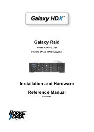
<strong>Rorke</strong> <strong>Data</strong> <strong>Galaxy</strong> <strong>HDX</strong> <strong>FC</strong> <strong>Subsystem</strong><br />
<strong>Quick</strong> <strong>Installation</strong> <strong>Guide</strong><br />
1. The system is heavy even without disks installed. At least two (2) people will be required to install the subsystem.<br />
2. The rack cabinet into which this subsystem will be installed must support overcurrent protection and must not be<br />
overloaded by the modules installed. Other requirements, such as ventilation airflow, rack stabilizing features,<br />
electrical earth, and electrical distribution, must comply with the technical specifications listed in the documentation<br />
that came with this product.<br />
3. System Integrators should ensure that any integrated storage solution that includes this product has been tested<br />
and proved to meet government regulations and codes for subjects including safety, fire, and electrical.<br />
4. The <strong>Galaxy</strong> <strong>HDX</strong> <strong>FC</strong> comes with a 256MB capacity or above DDR RAM DIMM module installed in its RAID<br />
controller unit.<br />
5. The battery backup module is an optional item and is not included in this kit.<br />
6. Make sure you have a soft, clean surface on which to place your subsystem before working on it. Placing the<br />
system on a rough surface during servicing may damage the chassis finish.<br />
7. Do not remove any module or component item from its anti-static bag until you are ready to install it. Pick up and<br />
hold modules by their edges or canister. Avoid touching PCBs and connector pins.<br />
8. Observe all standard ESD prevention methods, e.g., wear an anti-static wristband to prevent static electricity from<br />
damaging the electric components.<br />
9. The <strong>Galaxy</strong> <strong>HDX</strong> <strong>FC</strong> can be front- or rear-mounted in a variety of 19–inch-wide (48.26 cm) racks. The slide rail<br />
mounting kit is optional.<br />
<strong>Installation</strong> Procedures<br />
1. Unpacking the <strong>Subsystem</strong><br />
2. Hard Drive <strong>Installation</strong><br />
3. Drive Tray <strong>Installation</strong><br />
4. <strong>Subsystem</strong> Cable Connections<br />
5. Power On<br />
6. Install optional Battery Backup<br />
Unit (BBU) module<br />
7. Optional Dongle Kit <strong>Installation</strong><br />
8. Hard Drive <strong>Installation</strong> with<br />
Dongle Kit<br />
Unpacking the <strong>Subsystem</strong><br />
Pre-installed Modules<br />
1. LCD panel<br />
2. Front handles<br />
3. Controller module<br />
4. DDR RAM DIMM module<br />
5. Cooling modules<br />
6. Power supply units (PSUs)<br />
7. Backplane board<br />
Modules to be Installed<br />
1. Hard drives<br />
2. Drive trays<br />
3. Power cords<br />
4. RS-232C (audio-jack to DB9)<br />
serial cable<br />
5. Ethernet cable(s)<br />
6. Battery Backup Unit (BBU)<br />
(Optional)<br />
7. Dongle kits (Optional)<br />
Check the included Unpacking Checklist and verify the model name and shipping contents against the checklist.<br />
Hard Drive <strong>Installation</strong><br />
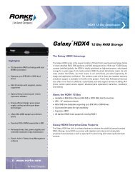
The <strong>Galaxy</strong> <strong>HDX</strong> <strong>FC</strong> subsystem supports SATA-I, SATA-II, and PATA<br />
hard drives. If you are going to use PATA drives in your system,<br />
optional dongle kits must be installed in each drive tray.<br />
Hard drive installation without a dongle kit<br />
1. Place the SATA-I or SATA-II hard drive into the drive tray.<br />
Make sure that the hard drive is oriented in such a way that<br />
the Series ATA (SATA) connector is facing the back of the<br />
drive tray.<br />
2. Adjust the drive’s location until the mounting holes in the drive<br />
canister are aligned with those on the hard drive. Secure the<br />
drive with four (4) of the supplied 6/32 flat-head screws. (See<br />
Figure 1)<br />
Drive Tray <strong>Installation</strong><br />
1. Turn the key-lock to the unlocked position. The key-lock is<br />
unlocked if the groove on its face is in a horizontal<br />
orientation. (See Figure 2)<br />
2. Open the front flap on the drive tray by pushing the button on<br />
the front of the drive tray in an upward direction. The button is<br />
easy to access. (See Figure 3)<br />
Figure 1: Installing the SATA Drive<br />
Figure 2: Drive Canister Front View<br />
Figure 3: Opening Drive Tray Front Flap<br />
<strong>Rorke</strong> <strong>Galaxy</strong> <strong>HDX</strong> <strong>FC</strong> <strong>Quick</strong> <strong>Installation</strong> <strong>Guide</strong>, rev. 1.0 PN: MA16FAHT16
3. Line the drive tray up with the slot in which you wish to insert it.<br />
Make sure that it is resting on the rails inside the enclosure.<br />
Once the drive tray is lined up with the slot, gently slide it in. This<br />
should be done smoothly and gently.<br />
4. Close the front flap on the drive tray. Make sure the front flap is<br />
closed properly to ensure that the SATA connector at the back of<br />
the drive tray is firmly connected to the corresponding connector<br />
on the mid-plane board. If the front flap is not closed properly,<br />
then the connection between the HDD and the subsystem will<br />
not be secure. To lock the flap in place, turn the key-lock until<br />
the groove on its face is in a vertical orientation. (See Figure 4)<br />
<strong>Subsystem</strong> Cable Connections<br />
Power Cables<br />
1. Connect the two (2) provided power cables to the power sockets<br />
on the back of the system. (See Figure 5)<br />
2. Make sure the power source is within the correct power range<br />
(100 to 240VAC) prior to powering on. Auto-ranging is supported<br />
by the power supply modules.<br />
3. Plug the other end of power cords into the power source.<br />
Host Ports<br />
The <strong>FC</strong>-to-SATA controller modules come with two SFP port sockets at<br />
the rear of the controller module for host connectivity and can be seen<br />
in Figure 6. (Details on <strong>FC</strong> cables and SFP ports can be found in<br />
Hardware Manual).<br />
COM Ports<br />
Each controller module comes with two (2) COM ports. The port on the<br />
left (COM1) is reserved for terminal emulation management. This port<br />
can be used to assign a permanent IP to the <strong>Galaxy</strong> subsystem. The<br />
port on the right (COM2) is used for UPS connectivity. One (1) audiojack<br />
to DB9 cable is provided to facilitate the connection of COM1 port.<br />
Purchase an additional cable to connect the subsystem to a UPS<br />
through the COM2 port. (See Figure 6)<br />
RJ-45 Ethernet Port<br />
After the <strong>Galaxy</strong> subsystem has been assigned a permanent IP, a shielded Ethernet cables can be used to connect the<br />
RJ-45 Ethernet port to a hub on a network, enabling you to manage your subsystem via the web. (See Figure 6)<br />
Power On<br />
To power on the subsystem, follow these steps:<br />
Figure 4: Drive Tray Key-Lock Rotation<br />
Figure 5: Power Supply Module<br />
Figure 6: Controller Module Interfaces<br />
1. Install all the hardware components.<br />
2. Make all the connections described above.<br />
3. Power on the subsystem by turning on both power switches on the rear panel of PSU modules. For the location of the<br />
power switches, please see Figure 5.<br />
4. Power on the host computer(s). Please refer to the user’s manual that came with your host computer for the power on<br />
procedure.<br />
<strong>Rorke</strong> <strong>Galaxy</strong> <strong>HDX</strong> <strong>FC</strong> <strong>Quick</strong> <strong>Installation</strong> <strong>Guide</strong>, rev. 1.0 PN: MA16FAHT16
Optional Battery Backup Unit (BBU) <strong>Installation</strong><br />
The BBU module is an optional item that must be purchased<br />
separately. Prior to installing the BBU module, power off the<br />
subsystem or restart the subsystem after the installation. To install the<br />
BBU, please follow these instructions:<br />
1. Remove the BBU slot dummy plate by loosening the two (2)<br />
retention screws located on both sides of the plate then pull<br />
it out of the chassis. (See Figure 7)<br />
2. Align the BBU module with the BBU module slot. Gently<br />
insert the BBU module until the back of the BBU module<br />
reaches the end of the slot. Secure the BBU module to the<br />
chassis by tightening the two (2) retention screws on the<br />
back of the BBU module. (See Figure 8)<br />
Optional Dongle Kit <strong>Installation</strong><br />
The dongle kit is an optional item. If you plan to install PATA drives in<br />
your subsystem, you must purchase and install the dongle kits before<br />
installing the hard drives.<br />
1. The dongle kit is mounted onto a metal base plate that has<br />
three (3) pre-drilled holes reserved for retention screws.<br />
(See Figure 9)<br />
2. Three (3) corresponding pre-drilled screw holes are located<br />
at the back of the drive tray.<br />
3. Place the dongle kit at the back of the drive tray. Hold the<br />
dongle kit in place and turn the drive tray over. Align the<br />
holes in the base of the drive tray with the holes in the<br />
dongle kit base tray.<br />
4. Insert the three (3) provided retention screws from the<br />
bottom of the drive tray. These screws firmly secure the<br />
dongle kit to the drive tray and facilitate the installation of the<br />
appropriate drive. (See Figure 10)<br />
Hard Drive <strong>Installation</strong> with Dongle Kit<br />
1. For PATA drives, connect the ATA and power cables from<br />
the dongle kit to the hard drive. Make sure that these<br />
connections are secure and will not come loose. (See Figure<br />
11)<br />
2. Once the dongle kit connectors are firmly attached to the<br />
hard drive, place the hard drive into the drive tray.<br />
3. Adjust the drive’s location until the mounting holes in the<br />
drive canister are aligned with those on the hard drive.<br />
Secure the drive with four (4) of the supplied 6/32 flat-head<br />
screws. (See Figure 12)<br />
Once the hard drives are installed into drive trays, install all<br />
sixteen (16) drive trays into the subsystem. Please refer to the<br />
drive tray installation in this installation guide or user’s manual in<br />
the product utility CD.<br />
Figure 7: Removing the BBU Slot Dummy Plate<br />
Figure 8: Installing the BBU Module<br />
Figure 9: SATA-to-PATA Dongle Kit<br />
Figure 10: Dongle Kit Retention Screw Locations<br />
Figure 11: PATA Hard Drive Connectors<br />
Figure 12: Installing the PATA Drive<br />
<strong>Rorke</strong> <strong>Galaxy</strong> <strong>HDX</strong> <strong>FC</strong> <strong>Quick</strong> <strong>Installation</strong> <strong>Guide</strong>, rev. 1.0 PN: MA16FAHT16
RAID function Limitation<br />
Feature Options Default Value<br />
64-bit LBA support (>2TB) Yes Yes<br />
Number of LD 16(Max.) 16<br />
Number of LV 8(Max.) 8<br />
Number of partitions per LD 8(Max.) 8<br />
Number of LUN per channel LD 32(Max.) 8<br />
Number of LUN support 128(Max.) ---<br />
Optimization mode Seq. I/O or Random I/O Seq. I/O<br />
Caching mode Write-Thru or Write-Back Write-Back<br />
Striping size-Sequential IO (RAID 5) 4/8/16/32/64/128/256KB 128KB<br />
Auto-assign global spare Enable/Disable Disable<br />
Optimization<br />
capacity<br />
for sequential mode of LD 64TB(Max.) 64TB<br />
Number of media scan task scheduler 16(Max.) 16<br />
Number of host ID/LUN per channel ID 32(Max.) 8<br />
Member drives / DIMM (RAID5) of LD 128 drives (Max.) / 512MB<br />
112 drives (Max.) / 256MB<br />
---<br />
For more details on the Firmware, please refer to the Firmware Generic operation Manual that came with your<br />
“Product Utility CD”.<br />
<strong>Rorke</strong> <strong>Galaxy</strong> <strong>HDX</strong> <strong>FC</strong> <strong>Quick</strong> <strong>Installation</strong> <strong>Guide</strong>, rev. 1.0 PN: MA16FAHT16