Galaxy Aurora 36Bay Hardware Manual v2.1 - Rorke Data
Galaxy Aurora 36Bay Hardware Manual v2.1 - Rorke Data
Galaxy Aurora 36Bay Hardware Manual v2.1 - Rorke Data

Create successful ePaper yourself
Turn your PDF publications into a flip-book with our unique Google optimized e-Paper software.
ISO 9001:2008<br />
ISO 13485:2003 Certified<br />
MODELS:<br />
» <strong>Aurora</strong> 36 Bay Models<br />
36TB-108TB<br />
4 - 8 FC Ports<br />
www.rorke.com<br />
Gaur36bay 080111HMNv1<br />
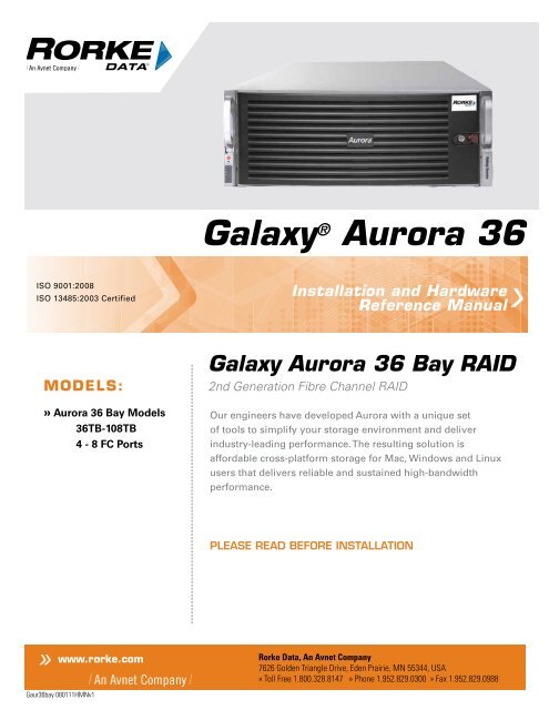
<strong>Galaxy</strong> ® <strong>Aurora</strong> 36<br />
Installation and <strong>Hardware</strong><br />
Reference <strong>Manual</strong><br />
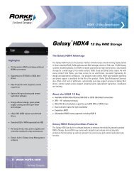
<strong>Galaxy</strong> <strong>Aurora</strong> 36 Bay RAID<br />
2nd Generation Fibre Channel RAID<br />
Our engineers have developed <strong>Aurora</strong> with a unique set<br />
of tools to simplify your storage environment and deliver<br />
industry-leading performance. The resulting solution is<br />
affordable cross-platform storage for Mac, Windows and Linux<br />
users that delivers reliable and sustained high-bandwidth<br />
performance.<br />
PLEASE READ BEFORE INSTALLATION<br />
<strong>Rorke</strong> <strong>Data</strong>, An Avnet Company<br />
7626 Golden Triangle Drive, Eden Prairie, MN 55344, USA<br />
» Toll Free 1.800.328.8147 » Phone 1.952.829.0300 » Fax 1.952.829.0988
<strong>Galaxy</strong> ® <strong>Aurora</strong> Series<br />
36 bay RAID Storage System<br />
Configuration and System<br />
Integration Guide<br />
Version 1.0<br />
August 2011
GALAXY® AUROURA 36BAY CONFIGURATION AND SYSTEM INTEGRATION GUID E<br />
1<br />
<strong>Rorke</strong> <strong>Data</strong>, an Avnet Company<br />
7626 Golden Triangle Drive<br />
Eden Prairie MN 55344-3732<br />
952 829 0300<br />
rorke-sales@avnet.com<br />
rorke-support@avnet.com<br />
This manual is preliminary and under construction and only applies to the <strong>Galaxy</strong>®<br />
36bay <strong>Aurora</strong> product. Contact <strong>Rorke</strong> Tech support for specific technical<br />
information regarding this manual.<br />
Version 1.0 August 16, 2011
GALAXY® AUROURA 36BAY CONFIGURATION AND SYSTEM INTEGRATION GUID E<br />
Table of Contents<br />
Copyright 2011 ................................................................................................................................................................. 5<br />
Disclaimer .......................................................................................................................................................................... 5<br />
Trademarks ....................................................................................................................................................................... 5<br />
Notices ................................................................................................................................................................................ 5<br />
Safety Precautions .......................................................................................................................................................... 6<br />
Precautions and Instructions ....................................................................................................................................... 6<br />
ESD Precautions .............................................................................................................................................................. 6<br />
Conventions ...................................................................................................................................................................... 7<br />
<strong>Galaxy</strong> <strong>Aurora</strong> 36bay EOS Updates ............................................................................................................................ 8<br />
1.0 Introduction and Overview ................................................................................................................................. 10<br />
1.1 Product Specifications ........................................................................................................................................ 10<br />
1.1.1 Overview ............................................................................................................................................................... 10<br />
1.1.2 Basic Features and Advantages .................................................................................................................... 11<br />
1.2 Model Variations .................................................................................................................................................. 12<br />
1.2.1 <strong>Galaxy</strong> <strong>Aurora</strong> 36bay Model Descriptions ................................................................................................... 12<br />
1.3 Product Description ............................................................................................................................................ 13<br />
1.3.1 Description of Physical Components .......................................................................................................... 13<br />
1.3.2 Component specifications ................................................................................................................................ 15<br />
1.3.3 RAID storage specifications ............................................................................................................................ 16<br />
1.3.4 Embedded OS features .................................................................................................................................... 16<br />
1.4 Mounting / Securing <strong>Aurora</strong> ............................................................................................................................... 17<br />
1.4.1 Rack Mounting the <strong>Aurora</strong> ................................................................................................................................ 17<br />
1.4.2 Installation Sequence ....................................................................................................................................... 18<br />
1.4.2.1 Ball Bearing Slide Rail Rack Installation .................................................................................................... 19<br />
2
GALAXY® AUROURA 36BAY CONFIGURATION AND SYSTEM INTEGRATION GUID E<br />
2.0 Basic Setup ............................................................................................................................................................ 26<br />
2.1 Drive integration and Cable Connections ...................................................................................................... 26<br />
2.1.1 Indicators and switch descriptions Figure 2.1 .......................................................................................... 26<br />
2.1.2 Installing drives into the <strong>Aurora</strong> Figure 2.2 ............................................................................................. 27<br />
2.1.3 Connecting Cables Figure 2.3 ...................................................................................................................... 28<br />
2.2 Configuration Setup ............................................................................................................................................. 29<br />
2.2.1 Setting up Ethernet Connectivity on a Windows Client .......................................................................... 29<br />
2.2.2 Installing Fibre Channel HBA and drivers on <strong>Aurora</strong> Clients ................................................................ 31<br />
2.2.3 Installing Infiniband HCA and drivers on <strong>Aurora</strong> Windows / Linux Clients ....................................... 31<br />
2.2.4 Linux Client RAID Connections and LUN Preparation ............................................................................ 31<br />
2.2.5 Windows Client RAID Connections and LUN Preparation ..................................................................... 35<br />
2.2.6 Apple OSX 10.6 Client RAID Connections and LUN Preparation ......................................................... 41<br />
2.2.7 Setting up a SAN with <strong>Aurora</strong>[s] using a Fibre Channel Switch ........................................................... 48<br />
3.0 <strong>Aurora</strong> 36bay GUI Detailed Operations ............................................................................................................ 50<br />
3.1 GUI Menu Details and Functions ....................................................................................................................... 50<br />
3.1.1 Main GUI screen page details and Quick Start functions ....................................................................... 50<br />
3.1.2 RAID Creation, Status, and other RAID configuration information ...................................................... 52<br />
3.1.3 RAID Details ....................................................................................................................................................... 54<br />
3.1.4 Scan / Performance Results ........................................................................................................................... 58<br />
3.1.5 LUN Details ......................................................................................................................................................... 60<br />
3.1.6 CONFIG Details .................................................................................................................................................. 62<br />
3.1.7 TRACE Details ................................................................................................................................................... 66<br />
3.1.8 USER Details ...................................................................................................................................................... 70<br />
3.1.9 PARAM Details ................................................................................................................................................... 71<br />
3.1.10 DATARATE Details ........................................................................................................................................ 75<br />
3.1.11 SLOT Details ....................................................................................................................................................... 80<br />
3.1.12 SENSOR Details ............................................................................................................................................. 85<br />
3
GALAXY® AUROURA 36BAY CONFIGURATION AND SYSTEM INTEGRATION GUID E<br />
3.1.13 ADAPTER Details ........................................................................................................................................... 86<br />
Troubleshooting <strong>Aurora</strong> 36bay .................................................................................................................................. 88<br />
4.1 Chassis Status Indicators .................................................................................................................................. 88<br />
4.2 GUI status indicators........................................................................................................................................... 89<br />
4.3 Power System ....................................................................................................................................................... 89<br />
4.4 FAN problems ....................................................................................................................................................... 90<br />
4.5 Power Supply problems ..................................................................................................................................... 90<br />
4.5.1 Replacing a Power Supply Module ............................................................................................................... 90<br />
4.6 DC Power Distribution problems ..................................................................................................................... 91<br />
4.7 Chassis Problems ................................................................................................................................................ 91<br />
4.8 Motherboard problems ....................................................................................................................................... 92<br />
4.9 Drive Backplane problems ................................................................................................................................. 94<br />
4.10 <strong>Data</strong> Drive problems ......................................................................................................................................... 94<br />
4.10.1 Drive Replacement ........................................................................................................................................ 94<br />
4.11 SAS HBA problems .......................................................................................................................................... 96<br />
4.12 Infiniband HCA problems ................................................................................................................................ 96<br />
4.13 Infiniband Host Cable / Connectivity issues .............................................................................................. 97<br />
4.14 Fibre HBA problems ......................................................................................................................................... 97<br />
4.15 Fibre Host connectivity issues ...................................................................................................................... 97<br />
4.16 Troubleshooting <strong>Aurora</strong> 36bay’s Client Related Problems ................................................................... 98<br />
4.16.1 Fibre Based Clients ........................................................................................................................................... 98<br />
4.17.2 Infiniband Based Clients ............................................................................................................................... 100<br />
4.17 Using IPMI to diagnose problems ............................................................................................................... 101<br />
5.0 Application / Technical / Customer Notes ................................................................................................... 106<br />
5.1 Additional Administration Functions ............................................................................................................ 106<br />
5.2 System Information ........................................................................................................................................... 106<br />
5.3 Setting System Time or Timezone ................................................................................................................. 107<br />
4
GALAXY® AUROURA 36BAY CONFIGURATION AND SYSTEM INTEGRATION GUID E<br />
5.4 Logging Out ......................................................................................................................................................... 108<br />
Copyright 2011<br />
This Edition First Published 2011 All rights reserved. This publication may not be<br />
reproduced, transmitted, transcribed, stored in a retrieval system, or translated into<br />
any language or computer language, in any form or by any means, electronic,<br />
mechanical, magnetic, optical, chemical, manual or otherwise, without the prior<br />
written consent.<br />
Disclaimer<br />
<strong>Rorke</strong> <strong>Data</strong> makes no representations or warranties with respect to the contents hereof<br />
and specifically disclaim any implied warranties of merchantability or fitness for any<br />
particular purpose. Furthermore, <strong>Rorke</strong> <strong>Data</strong> reserves the right to revise this publication<br />
and to make changes from time to time in the content hereof without obligation to notify<br />
any person of such revisions or changes. Product specifications are also subject to<br />
change without prior notice.<br />
Trademarks<br />
<strong>Rorke</strong> <strong>Data</strong> and the <strong>Rorke</strong> <strong>Data</strong> logo are registered trademarks of <strong>Rorke</strong> <strong>Data</strong>.<br />
<strong>Rorke</strong> <strong>Data</strong> and other names prefixed with “<strong>Aurora</strong> 36bay” and “<strong>Galaxy</strong>” are<br />
trademarks of <strong>Rorke</strong> <strong>Data</strong> in the United States, other countries, or both.<br />
All other names, brands, products or services are trademarks or registered<br />
trademarks of their respective owners.<br />
Notices<br />
The content of this manual is subject to change without notice. Although steps have<br />
been taken to create a manual which is as accurate as possible, it is possible this<br />
document may contain inaccuracies. Contact <strong>Rorke</strong> Tech Support for details.<br />
5
GALAXY® AUROURA 36BAY CONFIGURATION AND SYSTEM INTEGRATION GUID E<br />
Safety Precautions<br />
Precautions and Instructions<br />
• The <strong>Aurora</strong> 36bay weighs over 130 pounds requiring 2 people to properly move<br />
and mount it.<br />
• Be sure that the rack cabinet into which the subsystem chassis will be installed<br />
provides: sufficient strength and stability and ventilation channels and airflow<br />
circulation around the subsystem.<br />
• INSTALL AURORA 36BAY IN RACK MOUNTING BEFORE INSTALLING DISK<br />
DRIVES<br />
• The <strong>Aurora</strong> 36bay RAID subsystem will come with up to thirty six (36) drive bays.<br />
Leaving any of these drive bays empty will greatly affect the efficiency of the<br />
airflow within the enclosure, and will consequently lead to the system overheating,<br />
which can cause irreparable damage.<br />
• Prior to powering on the subsystem, ensure that the correct power range is being<br />
used.<br />
• If a disk or power supply module fails, leave it in place until you have a<br />
replacement unit and you are ready to replace it.<br />
• Airflow Consideration: The subsystem requires an airflow clearances on the sides,<br />
front and rear of the chassis.<br />
• Handle subsystem modules using the retention screws, extraction levers, and the<br />
metal frames/faceplates. Avoid touching PCB boards and connector pins.<br />
• To comply with safety, emission, or thermal requirements, none of the covers or<br />
replaceable modules should be removed. Make sure that during operation, all<br />
enclosure modules and covers are securely in place.<br />
• Provide a soft, clean surface to place your subsystem on before working on it.<br />
Servicing on a rough surface may damage the exterior of the chassis.<br />
• If it is necessary to transport the subsystem, repackage all disk drives separately.<br />
If using the original package material, other replaceable modules can stay within<br />
the enclosure.<br />
ESD Precautions<br />
6<br />
Observe all conventional ESD methods while handling system modules. The use of<br />
a grounded wrist strap and an anti-static work pad is recommended. Avoid dust and<br />
debris or other static-accumulative materials in your work area.
GALAXY® AUROURA 36BAY CONFIGURATION AND SYSTEM INTEGRATION GUID E<br />
Conventions<br />
Naming<br />
From this point on and throughout the rest of this manual, the <strong>Aurora</strong> 36bay series is<br />
referred to as simply the “ <strong>Aurora</strong> 36bay”, “subsystem” or the “system.”<br />
� Important Messages<br />
7<br />
Important messages appear where mishandling of components is possible or when<br />
work orders can be mis-conceived. These messages also provide important<br />
information associated with other aspects of system operation. The word “important”<br />
is written as “IMPORTANT,” both capitalized and bold, and is followed by text in<br />
italics. The italicized text is the message to be delivered.<br />
� Warnings<br />
Warnings appear where overlooked details may cause damage to the equipment or<br />
result in personal injury. Warnings should be taken seriously. Warnings are easy to<br />
recognize. The word “warning” is written as “WARNING,” both capitalized and bold<br />
and is followed by text in italics. The italicized text is the warning message.<br />
� Cautions<br />
� Notes<br />
Cautionary messages should also be heeded to help you reduce the chance of<br />
losing data or damaging the system. Cautions are easy to recognize. The word<br />
“caution” is written as “CAUTION,” both capitalized and bold and is followed by text<br />
in italics. The italicized text is the cautionary message.<br />
These messages inform the reader of essential but non-critical information. These<br />
messages should be read carefully as any directions or instructions contained<br />
therein can help you avoid making mistakes. Notes are easy to recognize. The word<br />
“note” is written as “NOTE,” both capitalized and bold and is followed by text in<br />
italics. The italicized text is the cautionary message.
GALAXY® AUROURA 36BAY CONFIGURATION AND SYSTEM INTEGRATION GUID E<br />
<strong>Galaxy</strong> <strong>Aurora</strong> 36bay EOS Updates<br />
Please contact your system vendor for the latest software updates.<br />
� Note: the version installed on your system should provide the complete functionality<br />
listed in the specification sheet/user’s manual.<br />
We provide special revisions for various application purposes. However, DO NOT upgrade your<br />
software unless you fully understand what a revision will do. Problems that occur during the<br />
updating process may cause unrecoverable errors and system down time. Always consult<br />
technical personnel before proceeding with any upgrade.<br />
8
GALAXY® AUROURA 36BAY CONFIGURATION AND SYSTEM INTEGRATION GUID E<br />
This page left blank intentionally<br />
9
GALAXY® AUROURA 36BAY CONFIGURATION AND SYSTEM INTEGRATION GUID E<br />
1.0 Introduction and Overview<br />
1.1 Product Specifications<br />
1.1.1 Overview<br />
10<br />
Section 1<br />
Introduction and Overview<br />
The <strong>Aurora</strong> RAID 36bay Array is the newest member of the <strong>Galaxy</strong> family of RAID<br />
Storage System products. It is a (4U) rack mount RAID solution that is designed for<br />
your ultra high speed data storage needs.<br />
As with the earlier <strong>Galaxy</strong> <strong>Aurora</strong> 24 bay RAID products, the <strong>Galaxy</strong> <strong>Aurora</strong> 36bay is<br />
characterized by many of the same outstanding features and attributes as those of<br />
the <strong>Aurora</strong> family members. The most noticeable feature is that this RAID is blazingly<br />
fast while being surprisingly affordable. Other features include a preloaded Linux<br />
operating system and RAID Engine Software called EOS which does all the work of a<br />
normal RAID controller without the cost and dependency of other ASIC based<br />
controllers. RAID 6 [ dual parity RAID ], RAID 0 [ striping ], RAID 1 [ mirroring ] and<br />
RAID 10 [ Striped mirrored ] are supported to give the best of both worlds, ultra<br />
reliable data protection or blazingly fast performance. Of course speeds that exceed<br />
4000Mbytes/ second would be no good without the host connectivity which is built<br />
into the unit. <strong>Aurora</strong> 36bay is capable of supporting up to 8 ports of 8Gb Fibre<br />
Channel or 2 ports of 40Gb Infiniband and with SAN connectivity connect to many<br />
more. Optical cable connectivity is available in various lengths to make direct or<br />
switch connections easy. Target mapping gives you the best ability to assign specific<br />
ports specific storage use without fear of seeing or using other storage locations in<br />
the RAID. Other features include, easy to use GUI storage management tools,<br />
integrated software functions that help ease configuration and use, ease of
G A LAXY® AUROURA 36 BAY CONFIGURATION AND SYSTEM INTEGRATION GUIDE<br />
deployment in the network, as well as built-in tools to facilitate remote management<br />
and systems management. With our “SAN in a Box” feature, we use SAN software<br />
as well as the Metadata controller [MDC] features needed to run the SAN software.<br />
An optional external MDC may be required for specific SAN configurations.<br />
1.1.2 Basic Features and Advantages<br />
The <strong>Galaxy</strong> <strong>Aurora</strong> 36 bay RAID provides these important features and advantages:<br />
• Compact 4RU Steel and Aluminum Alloy enclosure with rack mount kit.<br />
• 4000+ MB/s sustained bandwidth over a Infiniband cable or 8Gb Fibre cables<br />
• Intel Core i7 Xeon processor and motherboard<br />
• Latest SATA / SAS drive controllers<br />
• 64 bit Linux based OS<br />
• EOS embedded RAID Engine and GUI application<br />
• RAID level 6, dual parity RAID protection<br />
• RAID level 0,1,10 RAID functions<br />
• Up to 8 X 8Gb Fibre Channel and 2 X 40Gb Infiniband support<br />
• 36 Removable Hot Swap Disk Drives<br />
• Over 2TB partition support for 32bit OS support<br />
• Web-based Graphical User Interface<br />
• Enhanced troubleshooting and parameter tools and settings<br />
• Remote Maintenance with browser or command line<br />
• Remote <strong>Hardware</strong> Status monitoring<br />
• Supports Optional SAN Software such as HyperFS: supporting full file locking<br />
and enables protected, concurrent read/write access by all attached clients<br />
• Target Mapping and Client supported LUN partitioning<br />
• Background Activities that include: RAID Rebuild; SMART condition polling;<br />
Media health monitoring and repair<br />
• Secured Administration Access<br />
• Simultaneous Fibre channel and Infiniband interface Support<br />
• Redundant Power Supplies<br />
• UPS Support and Network UPS Support<br />
• Secure front bezel protection<br />
• CLI Console Tool as well as Remote Console<br />
• Supporting configurations that bridge Fibre and Gbit Networks<br />
11 Section 1 Intro and Overview
G A LAXY® AUROURA 36 BAY CONFIGURATION AND SYSTEM INTEGRATION GUIDE<br />
1.2 Model Variations<br />
1.2.1 <strong>Galaxy</strong> <strong>Aurora</strong> 36bay Model Descriptions<br />
The <strong>Aurora</strong> 36 Bay is based on a primary model with many storage variations:<br />
For ease of purpose, the main portion of the manual will<br />
be based on the GAUR36-4F8-36TB version of the <strong>Aurora</strong> .<br />
12 Section 1 Intro and Overview
G A LAXY® AUROURA 36 BAY CONFIGURATION AND SYSTEM INTEGRATION GUIDE<br />
1.3 Product Description<br />
1.3.1 Description of Physical Components<br />
See the figure below for a diagram of the front of the <strong>Galaxy</strong> <strong>Aurora</strong>. To access the<br />
drive area, simple unlock and push the red handled bezel latch to the left. The bezel<br />
will be free to swing off the front of the unit, exposing the drive area.<br />
Figure 1.3.1a<br />
Front<br />
Controls<br />
Drive Area<br />
The figure below shows a detailed diagram of the front controls area:<br />
Figure 1.3.1b<br />
Power Switch<br />
Reset Switch<br />
Power LED<br />
Boot Drive Activity LED<br />
Ethernet Port 1 Activity LED<br />
Ethernet Port 2 Activity LED<br />
Temperature Warning LED<br />
Power Warning LED<br />
The figure on the following page shows a diagram of the rear of the <strong>Galaxy</strong> <strong>Aurora</strong> .<br />
Note that this configuration may be slightly different than your actual <strong>Aurora</strong> .<br />
13 Section 1 Intro and Overview
G A LAXY® AUROURA 36 BAY CONFIGURATION AND SYSTEM INTEGRATION GUIDE<br />
Figure 1.3.1c<br />
E<br />
B<br />
J<br />
G<br />
I<br />
D<br />
C<br />
A<br />
O W X Y 1 2 3 4<br />
H F K L M N P Q R S T U V<br />
A) Upper Power Supply Module S) Network Port 1 Link LED<br />
B) Upper Power Supply Handle T) Network Port 2 Activity LED<br />
C) Upper Power Cord Connector U) Network Port 2<br />
D) Upper Power Status LED V) Network Port 2 Link LED<br />
E) Upper Module Removal Lever W) IPMI Network Port<br />
F) Lower Power Supply Module X) IPMI Activity LED<br />
G) Lower Power Supply Handle Y) IPMI Activity LED<br />
H) Lower Power Cord Connector 1) Fibre / IB Host Card<br />
I ) Lower Power Status LED 2) Fibre / IB Host Card<br />
J) Lower Module Removal Lever 3) Fibre / IB Host Card<br />
K) PS/2 Mouse Connector 4) Fibre / IB Host Card<br />
L) PS/2 Keyboard Connector<br />
M) USB Ports<br />
N) Serial Port (Not used)<br />
O) Exhaust Fan Area<br />
P) VGA Connector<br />
Q) Network Port 1 Activity LED<br />
R) Network Port 1<br />
Facing the rear, the two power supply modules are located on the left. Above each<br />
power connector is an LED which is on if the power supply module is operating and<br />
receiving power. If either of these LEDs goes out, it could mean that the power cable<br />
isn't operating properly, the module isn't seated all the way, or there is a problem with<br />
the power supply, the module itself, or the AC outlet. The <strong>Galaxy</strong> <strong>Aurora</strong> has loadbalancing,<br />
redundant power supplies, which means that if either module stops<br />
working, the unit will continue to work (albeit with a beeper warning). To remove a<br />
14 Section 1 Intro and Overview
G A LAXY® AUROURA 36 BAY CONFIGURATION AND SYSTEM INTEGRATION GUIDE<br />
power supply module, you have to remove the power cord first, then rotate out the<br />
metal handle from the bottom. Push the red lever to the right, while pulling the<br />
module out. To reinsert the module, just push it in until it clicks, then fold the handle<br />
down.<br />
The two round connectors on the left are for a PS/2 keyboard or a mouse. The green<br />
connector is for a mouse, and the purple connector is for a keyboard. To the right of<br />
these two connectors are USB connectors. These can be used for USB drive(s),<br />
memory key(s), hub(s), and/or a USB keyboard or mouse. To the right of the USB<br />
connectors is a green serial connector. It is not used. To the right of the serial<br />
connector is an analog VGA connector. You may attach a console monitor here. To<br />
the right of the VGA connector are two gigabit Ethernet ports. The left port (if you are<br />
facing the rear) is port 1, the right port is port 2.<br />
The vertical slits on the right (called slots) hold the host adapters which are inside the<br />
system. Going from left to right, there is a SAS host adapter used for the RAID drives.<br />
To the right of this adapter is either a Fibre Channel or Infiniband Host Bus Adapter<br />
depending on the configuration you selected. Above the USB ports is the Ethernet<br />
port for the IPMI card.<br />
1.3.2 Component specifications<br />
The <strong>Aurora</strong> 36bay is a 4U 36-bay rack mountable storage enclosure that supports up<br />
to thirty-six hot-swappable hard disk drives. The Motherboard is a Intel Core i7 Xeon<br />
mother board with INTEL Processor. This board supports:<br />
Intel Core i7 Xeon CPU<br />
EOS RAID application and RAID GUI<br />
On board externally connected video, mouse, and keyboard<br />
On board dual 1Gb Ethernet ports<br />
Ships with 24GB DDR RAM<br />
Up to 7 PCI-E half high slots<br />
Supports up to 36 x 3.5", 1.0" 6Gb SAS half-height hard disk drives<br />
{storage size and speeds vary depending on model]<br />
Twenty four front mounted and twelve rear mounted hot-swappable hard disk<br />
drive bays<br />
Integrated backplane design that supports 6Gb SAS / SATA Disk Interface<br />
Built-in environment controller<br />
Enclosure management controller<br />
Redundant power supply<br />
Advanced thermal design with hot-swappable fans<br />
Front panel LED Function indicators<br />
15 Section 1 Intro and Overview
G A LAXY® AUROURA 36 BAY CONFIGURATION AND SYSTEM INTEGRATION GUIDE<br />
Shock and vibration proof design for high reliability<br />
Dimensions: 13.1x 44.65x 59.1 cm (7.0 x17.2 x 27.5in)<br />
Weight: Gross weight (including carton): 37.5kg (82.7 lbs) without drives,<br />
57.1 kg (126.0 lbs) with 36 drives<br />
Power Supply: Dual 1400W, 100-240 Vac auto-ranging, 50-60 Hz, dual hot<br />
swap and redundant with PFC, N+1 design<br />
Ventilation 7 x 8cm fans<br />
Environment Controller Internal Temperature - visible and audio alarm<br />
Individual Cooling and Ventilation fans<br />
1.3.3 RAID storage specifications<br />
The <strong>Aurora</strong> has sophisticated built in RAID software and drives that are preconfigured<br />
and prepared for you so it would be plug and play for most users. By<br />
default, the <strong>Aurora</strong> RAID has been configured with RAID 6 protection and set to the<br />
logical volume you have requested. For 32 bit Windows XP configurations, our<br />
special setting allow up to 16TB volumes to be created for you, instead of the<br />
standard 2TB.<br />
RAID 6 with its dual parity drive protection has been found to be the most protective<br />
while the least costly way of guarding against not only initially failed SAS disk drives<br />
but primarily against the total loss of the RAID data because a second SAS drive<br />
detects an error during the RAID rebuild process. A RAID 5 configuration in that<br />
scenario would cause the RAID not to rebuild properly.<br />
1.3.4 Embedded OS features<br />
�Important: The <strong>Aurora</strong> EULA restricts you, the user, from loading any other software, such as<br />
application software, onto the <strong>Aurora</strong>. Tampering with, loading or using any other software<br />
voids the license agreement.<br />
Each <strong>Aurora</strong> is preloaded at the factory with its base operating system, RAID<br />
application, installation, administration and optional SAN software. The code is<br />
loaded onto the system's boot device.<br />
In addition to the operating system and basic EOS embedded application software,<br />
each unit contains a web based browser interface which simplifies remote<br />
configuration and administration tasks.<br />
Specifically, the units come preconfigured with the following functions:<br />
EOS: Linux based RAID application and User configuration / troubleshooting<br />
interface<br />
16 Section 1 Intro and Overview
G A LAXY® AUROURA 36 BAY CONFIGURATION AND SYSTEM INTEGRATION GUIDE<br />
Remote system administration:<br />
Administrative tasks can be performed in the Web-based GUI<br />
Alternate administrative task performed using Windows Terminal Service<br />
Advanced management functions available via Windows Terminal Service<br />
Optional SAN Management Software<br />
1.4 Mounting / Securing <strong>Aurora</strong><br />
1.4.1 Rack Mounting the <strong>Aurora</strong><br />
The <strong>Aurora</strong> is a rack mounted chassis. Mounting holes on the front panel are set to<br />
RETMA spacing and will fit into any standard 19” equipment rack. Square or round<br />
hole mounting racks are available<br />
Rack Equipment Precautions<br />
These precautions and directions should be used only as an information source for<br />
planning your <strong>Aurora</strong> deployment. Avoid personal injury and equipment damage by<br />
following accepted safety practices.<br />
Floor Loading<br />
� CAUTION: Ensure proper floor support and ensure that the floor loading<br />
specifications are adhered to. Failure to do so may result in physical injury or damage<br />
to the equipment and the facility.<br />
Deployment of rack servers, related equipment, and cables exceeds 1800 pounds for<br />
a single 42U rack.<br />
External cable weight contributes to overall weight of the rack installation. Carefully<br />
consider cable weight in all designs<br />
Installation Requirement<br />
� CAUTION: Be aware of the center of gravity and tipping hazards. Installation<br />
should be such that a hazardous stability condition is avoided due to uneven loading.<br />
We recommend that the rack footings extend 10 inches from the front and back of<br />
any rack equipments 22U or higher.<br />
Adequate stabilization measures are required. Ensure that the entire rack assembly<br />
is properly secured and that all personnel are trained in proper maintenance and<br />
operation procedures. Tipping hazards include personal injury and death.<br />
17 Section 1 Intro and Overview
G A LAXY® AUROURA 36 BAY CONFIGURATION AND SYSTEM INTEGRATION GUIDE<br />
Power Input and Grounding<br />
� CAUTION: Ensure your installation has adequate power supply and branch<br />
circuit protection.<br />
Check nameplate ratings to assure there is no overloading of supply circuits that<br />
could have an effect on over current protection and supply wiring. Reliable grounding<br />
of this equipment must be maintained. Particular attention should be given to supply<br />
connections when connecting to power strips, rather than direct connections to the<br />
branch circuit.<br />
Thermal Dissipation Requirement<br />
� CAUTION: Thermal dissipation requirements of this equipment deployment<br />
mandate minimum unrestricted airspace of three inches in both the front and the rear.<br />
The ambient within the rack may be greater than room ambient. Installation should be<br />
such that the amount of air flow required for safe operation is not compromised. The<br />
maximum temperature for the equipment in this environment is 122°F (50°C).<br />
Consideration should be given to the maximum rated ambient.<br />
1.4.2 Installation Sequence<br />
� CAUTION: It is strongly recommended to securely fasten the mounting rack to<br />
the floor or wall to eliminate any possibility of tipping of the rack. This is especially<br />
important if you decide to install several <strong>Aurora</strong> chassis’ in the top of the rack.<br />
A brief overview of <strong>Aurora</strong> installation follows:<br />
1. Select an appropriate site for the rack.<br />
2. Unpack the <strong>Aurora</strong> and rack mounting hardware.<br />
3. Attach the rack mounting hardware to the rack and to the <strong>Aurora</strong>.<br />
4. Mount the <strong>Aurora</strong> into the rack.<br />
5. Connect the cables.<br />
6. Install the drives<br />
Decide on an appropriate location for the <strong>Galaxy</strong> <strong>Aurora</strong> . It is best if the unit is kept<br />
away from heat or from where high electromagnetic fields that may exist. If you are<br />
installing the unit into a rack, make sure the rack is in the proper location prior to<br />
installation. Moving the <strong>Galaxy</strong> <strong>Aurora</strong> while it is installed into the rack is not<br />
recommended.<br />
The <strong>Galaxy</strong> <strong>Aurora</strong> requires 4 rack units of vertical clearance (7 inches), and a depth<br />
of 28 inches. It is recommended that you mount it in a rack which is at least 30 inches<br />
deep.<br />
Airflow for the unit comes in through right side and the front. Heat exhaust is from the<br />
rear of the unit. It is important that airflow at the front or the rear not be blocked.<br />
18 Section 1 Intro and Overview
G A LAXY® AUROURA 36 BAY CONFIGURATION AND SYSTEM INTEGRATION GUIDE<br />
The rack slides permit the unit to slide out of the front of the rack. There are latches<br />
on the sides of the slides, and if you are planning on removing the unit from the rack<br />
to service or transport it, sufficient clearance should be available to allow you to<br />
activate the latches and unlatch the slides.<br />
If the rack is on wheels, be sure to use the wheel locks when installing or removing<br />
the <strong>Galaxy</strong> <strong>Aurora</strong> from the rack. If the rack does not have wheel locks, place<br />
something against the wheels to prevent movement, or if your rack is equipped with<br />
leveling jacks, extend the jacks to make sure the rack stays level during installation.<br />
Always make sure the rack is completely immobile before installing or removing any<br />
components. Never extend more than one component from the rack at the same<br />
time.<br />
There is a set of slides included with the <strong>Galaxy</strong> <strong>Aurora</strong>. The slides are required for<br />
rack-mounting the unit, and the slides must be mounted with the rear extensions<br />
installed into the rack. The weight of the unit is sufficient that if this were not<br />
performed, damage would result to the unit, the slides, or the rack if installed.<br />
When installing the slides, loosely attach the rear end of the slide to the front end,<br />
then screw the front and rear rack portions of the slides into the rack. Finally, tighten<br />
the screws between the two ends. Repeat this process for the other side. Once the<br />
slides are installed in the rack, slide the unit into the slides.<br />
1.4.2.1 Ball Bearing Slide Rail Rack Installation<br />
Unpack the package box and locate the materials and documentation necessary for<br />
rack mounting. All the equipment needed to install the server into the rack cabinet is<br />
included.<br />
Follow the instructions for each of these illustrations<br />
Identifying the Sections of the Rack Rails<br />
The chassis package includes two rail assemblies in the rack mounting kit. Each<br />
assembly consists of three sections: An inner chassis rail which secures directly to<br />
the chassis, an outer rail that secures to the rack, and a middle rail which extends<br />
from the outer rail. These assemblies are specifically designed for the left and right<br />
side of the chassis<br />
19 Section 1 Intro and Overview
G A LAXY® AUROURA 36 BAY CONFIGURATION AND SYSTEM INTEGRATION GUIDE<br />
Locking Tabs<br />
Indentifying the Outer Rail, Middle Rail and Inner Rails.<br />
[Left Rail Assembly shown as example]<br />
Each inner rail has a locking tab. This tab locks the chassis into place when installed<br />
and pushed fully into the rack. These tabs also lock the chassis in place when fully<br />
extended from the rack. This prevents the server from coming completely out of the<br />
rack when the chassis is pulled out for servicing.<br />
Releasing the Inner Rail<br />
Releasing Inner Rail from the Outer Rails<br />
1. Identify the left and right outer rail assemblies as described above.<br />
2. Pull the inner rail out of the outer rail until it is fully extended as illustrated 2.<br />
below.<br />
3. Press the locking tab down to release the inner rail.3.<br />
4. Pull the inner rail all the way out.4.<br />
5. Repeat steps 1-3 for the second outer rail.<br />
20 Section 1 Intro and Overview
G A LAXY® AUROURA 36 BAY CONFIGURATION AND SYSTEM INTEGRATION GUIDE<br />
Extending and Releasing the Inner Rail<br />
21 Section 1 Intro and Overview
G A LAXY® AUROURA 36 BAY CONFIGURATION AND SYSTEM INTEGRATION GUIDE<br />
Installing the Inner Rails<br />
Inner rails installed<br />
Installing the Inner Rails on the Chassis<br />
Installing the Inner Rails<br />
1. Confirm that the left and right inner rails have been correctly identified.1.<br />
2. Place the inner rail firmly against the side of the chassis, aligning the hooks 2.<br />
on the side of the chassis with the holes in the inner rail.<br />
22 Section 1 Intro and Overview<br />
I
G A LAXY® AUROURA 36 BAY CONFIGURATION AND SYSTEM INTEGRATION GUIDE<br />
3. Slide the inner rail forward toward the front of the chassis until the rail clicks 3.<br />
into the locked position, which secures the inner rail to the chassis.<br />
4. Secure the inner rail to the chassis with the screws provided. 4.<br />
5. Repeat steps 1 through 4 above for the other inner rail.<br />
Extending and Releasing the Outer Rails<br />
Installing the Outer Rails on the Rack<br />
Installing the Outer Rails<br />
1. Press upward on the locking tab at the rear end of the middle rail. 1.<br />
2. Push the middle rail back into the outer rail.2.<br />
3. Hang the hooks of the front of the outer rail onto the slots on the front of 3. the<br />
rack. If necessary, use screws to secure the outer rails to the rack, as<br />
illustrated above.<br />
4. Pull out the rear of the outer rail, adjusting the length until it fits within the 4.<br />
posts of the rack.<br />
5. Hang the hooks of the rear portion of the outer rail onto the slots on the rear 5.<br />
of the rack. If necessary, use screws to secure the rear of the outer rail to the<br />
rear of the rack.<br />
6. Repeat steps 1-5 for the remaining outer rail.<br />
23 Section 1 Intro and Overview
G A LAXY® AUROURA 36 BAY CONFIGURATION AND SYSTEM INTEGRATION GUIDE<br />
Standard Chassis Installation<br />
Installing the Chassis into a Rack<br />
1. Confirm that the inner rails are properly installed on the chassis. 1.<br />
2. Confirm that the outer rails are correctly installed on the rack. 2.<br />
3. Pull the middle rail out from the front of the outer rail and make sure that the 3.<br />
ball-bearing shuttle is at the front locking position of the middle rail.<br />
4. Align the chassis inner rails with the front of the middle rails.4.<br />
24 Section 1 Intro and Overview
G A LAXY® AUROURA 36 BAY CONFIGURATION AND SYSTEM INTEGRATION GUIDE<br />
5. Slide the inner rails on the chassis into the middle rails, keeping the pressure<br />
5. even on both sides, until the locking tab of the inner rail clicks into the front<br />
of the middle rail, locking the chassis into the fully extended position.<br />
6. Depress the locking tabs of both sides at the same time and push the chassis<br />
6. all the way into the rear of the rack.<br />
7. If necessary for security purposes, use screws to secure the chassis handles<br />
7. to the front of the rack.<br />
Adapters for Round and Threaded Hole Racks<br />
The chassis includes adapter brackets for those customers using round hole racks or<br />
racks with threaded holes size M5 or larger.<br />
Installing the Adapter Bracket<br />
Place the hooks of the front of the outer rail into the square holes of one of 1. the<br />
adapter brackets.<br />
Place the hooks of the rear of the outer rail into the square holes of a second 2.<br />
adapter bracket.<br />
Adjust the length of the outer rail to fit within the rack uprights.3.<br />
Secure the front adapter bracket to the front of the rack using the screws 4.<br />
recommended by the rack manufacturer.<br />
Secure the rear adapter bracket to the rear of the rack in the same manner.<br />
� CAUTION: Due to the weight of the chassis with the peripherals installed, lifting<br />
the chassis and attaching it to the cabinet may need additional manpower. If needed,<br />
use an appropriate lifting device.<br />
This completes the installation and rack mounting process.<br />
25 Section 1 Intro and Overview
G A LAXY® AUROURA 36 BAY CONFIGURATION AND SYSTEM INTEGRATION GUIDE<br />
2.0 Basic Setup<br />
2.1 Drive integration and Cable Connections<br />
Section 2<br />
Basic Setup<br />
2.1.1 Indicators and switch descriptions Figure 2.1<br />
The <strong>Aurora</strong> comes with a lockable, removable front bezel. Remove this bezel to<br />
access the operator panel that has indictors for operational and fault conditions and<br />
activity. Green LEDs indicate good condition, red LEDs indicate a problem that will<br />
also log an error. The alarm reset needs to be depressed to silence the alarm. The<br />
Reset PB is used to restart the <strong>Aurora</strong>. The Power PB is used to power up the<br />
<strong>Aurora</strong>.<br />
Figure 2.1<br />
Front<br />
Controls<br />
Drive Area<br />
Power Switch<br />
Reset Switch<br />
Power LED<br />
Boot Drive Activity LED<br />
Ethernet Port 1 Activity LED<br />
Ethernet Port 2 Activity LED<br />
Temperature Warning LED<br />
Power Warning LED<br />
The power switch is used to turn the unit on. However, do not use it to turn the unit<br />
off, unless there is no other way. To turn on the unit, press the power switch<br />
momentarily. To turn it off, press and hold it for 8 seconds. The reset switch also<br />
26 Section 2 Basic Setup
G A LAXY® AUROURA 36 BAY CONFIGURATION AND SYSTEM INTEGRATION GUIDE<br />
should not be used unless there is no alternative. It is pressed using a straightenedout<br />
paper clip. Below the two switches is the Power LED. This illuminates when<br />
power is on. Below the power LED is a disk activity LED for the internal boot drive.<br />
This LED will light intermittently during normal operation. Below the power LED are<br />
two network LEDs. These LEDs will light when there is activity from the ports they<br />
correspond to on the rear. Below these is a temperature warning LED. If the<br />
temperature inside the system becomes too high, this LED will illuminate. Below the<br />
temperature warning LED is a power warning LED. If there is something wrong with<br />
the power, this LED will illuminate.<br />
2.1.2 Installing drives into the <strong>Aurora</strong> Figure 2.2<br />
The <strong>Galaxy</strong> <strong>Aurora</strong> 36bay features 36 removable drives. They have been shipped<br />
separately to insure the <strong>Aurora</strong> would not incur shipping damages from a possible<br />
shipping related shock to the drives or backplane.<br />
� CAUTION: Be aware that the <strong>Aurora</strong>’s file system is installed and the drives must<br />
be placed into their prepared slots for the file system to operate properly.<br />
The front mounted drives will be tagged with numbers 0-23 and the rear mounted are<br />
tagged with 24-35. Place them in their assigned numbered slot in the <strong>Aurora</strong> chassis<br />
as shown below:<br />
Figure 2.2<br />
27 Section 2 Basic Setup
G A LAXY® AUROURA 36 BAY CONFIGURATION AND SYSTEM INTEGRATION GUIDE<br />
The drives are simple to install. Simply unwrap, push the red button to release the<br />
tray handle and push each drive into each empty drive opening as far as it will go,<br />
then push the handle in until the red button clicks into place. Each of the drive<br />
modules in the <strong>Galaxy</strong> <strong>Aurora</strong> has two LEDs. The upper LED flashes for disk activity,<br />
while the lower LED is used for errors and flash ID use. The RAID’s EOS software<br />
will scan to find all drives. To remove a drive module, push the red button until the<br />
black handle pops out. Then pull the handle until it is sticking straight forward, and<br />
carefully pull the drive out by the handle. To reinstall a drive, make sure the handle is<br />
sticking out of the module (if it's not, push the red button to release the handle),<br />
The <strong>Aurora</strong> OS has been preloaded and RAID storage preconfigured to be ready for<br />
you to power up and start configuring it for use. Before powering up, make the cable<br />
connections to, ethernet, power, keyboard, IPMI, Host connections, and monitor [ in<br />
certain cases these components nor cables are provided].<br />
2.1.3 Connecting Cables Figure 2.3<br />
See the illustration for the cable locations and connectivity.<br />
For safety reasons we recommend the cables be connected in the following order:<br />
Connect one power cord to an active powered AC outlet, then connect the other end<br />
to the rear of the <strong>Galaxy</strong> <strong>Aurora</strong>. You will hear a fan get loud, then get quiet – this is<br />
normal and nothing to be alarmed about.<br />
Connect the second power cord to a second active powered AC outlet (preferably at<br />
the same source as the first one), then connect the other end to the second power<br />
supply module on the back of the <strong>Galaxy</strong> <strong>Aurora</strong>. A fan may sound, then get quiet –<br />
this is normal and nothing to be alarmed about.<br />
Figure 2.3<br />
2 AC Power Cables<br />
PS2 Keybd / Mouse Monitor<br />
28 Section 2 Basic Setup<br />
DHCP<br />
192.168.1.129<br />
Monitor<br />
FC or IB ports<br />
Then connect the Ethernet cable to the right most ethernet connection. It has been a<br />
fixed IP address of 192.168.1.129. Connect the Fibre or Infiniband Host cables,<br />
monitor, keyboard and mouse as shown<br />
Depending on your configuration, an Infiniband or Fibre Channel Cable connection<br />
can either be connected point-to-point (I.e. directly to another computer with a host<br />
adapter), or can be connected to an Infiniband or Fibre Channel switch. The card slot<br />
and port id are as follows:
G A LAXY® AUROURA 36 BAY CONFIGURATION AND SYSTEM INTEGRATION GUIDE<br />
Facing the rear of the <strong>Aurora</strong> can be up to 4 Host card slots, each slot has 2<br />
connections on each HBA :<br />
Target port IDs for each HBA from left to right are:<br />
6 0 2 4<br />
7 1 3 5<br />
When all cables are installed, one or more of the Ethernet activity LEDs on the front<br />
of the unit may blink.<br />
Power up the <strong>Galaxy</strong> <strong>Aurora</strong> by momentarily pushing the Power switch on the front of<br />
the unit. The <strong>Galaxy</strong> <strong>Aurora</strong> will take several minutes to boot. When bootup is almost<br />
complete, all the red LEDs will illuminate briefly from bottom to top, then go out.<br />
2.2 Configuration Setup<br />
2.2.1 Setting up Ethernet Connectivity on a Windows Client<br />
For you to administer <strong>Aurora</strong>, setup remote maintenance, or proceed with SAN usage<br />
you need to be able to see the <strong>Aurora</strong> with a standard internet browser over ethernet<br />
from your client. The process below will allow the client to talk to the <strong>Aurora</strong> over<br />
ethernet on a Windows Client. Contact your Network Administrator for support.<br />
Proceed to the TCP/IP settings area of your particular client station, i.e. Windows<br />
control panel network settings and select properties. Select the TCP/IP listing and<br />
clik properties:<br />
29 Section 2 Basic Setup
G A LAXY® AUROURA 36 BAY CONFIGURATION AND SYSTEM INTEGRATION GUIDE<br />
Clik the button to ‘Use the following IP address:<br />
Setup the<br />
IP address to :192.168.1.2<br />
Subnet mask to : 255.255.255.0<br />
Default gateway to: 192.168.1.129<br />
30 Section 2 Basic Setup
G A LAXY® AUROURA 36 BAY CONFIGURATION AND SYSTEM INTEGRATION GUIDE<br />
DNS server info should be 192.168.1.129 [or blank on older Windows OS].<br />
Clik OK and your client can now see the <strong>Aurora</strong> over Ethernet using as standard<br />
Internet Browser.<br />
The <strong>Aurora</strong> has been setup at the factory with a fixed default IP address of :<br />
192.168.1.129<br />
2.2.2 Installing Fibre Channel HBA and drivers on <strong>Aurora</strong> Clients<br />
Consult with your local <strong>Aurora</strong> reseller for Windows, Linux, and Apple client HBA<br />
information.<br />
Go to the various Linux, Windows, or Apple File system preparation section of this<br />
manual to prepare the <strong>Aurora</strong> LUN for your clients.<br />
2.2.3 Installing Infiniband HCA and drivers on <strong>Aurora</strong> Windows / Linux Clients<br />
Because of changes to Infiniband drivers, HCAs, and OS, contact <strong>Rorke</strong> tech support<br />
for any Infiniband installation.<br />
2.2.4 Linux Client RAID Connections and LUN Preparation<br />
After the Linux Infiniband drivers are installed or the Fibre channel HBA drivers are<br />
installed and loaded, you should already have the block device representing the LUN<br />
mounted. If you type the following command you should get a list of mounted storage<br />
LUNs:<br />
lsscsi[enter]<br />
the following response will be displayed:<br />
[0:0:0:0] disk ATA HDS722516VLAT80 V34O /dev/sda<br />
[0:0:1:0] cd/dvd PIONEER DVD-RW DVR-109 1.40 /dev/sr0<br />
[2:0:0:0] disk <strong>Galaxy</strong>IB MyLUN 2424 /dev/sdb<br />
In the example above, the last line shows the <strong>Aurora</strong> LUN [<strong>Galaxy</strong>IB MyLUN]. The<br />
<strong>Aurora</strong> 36bay device manufacturer is shown as <strong>Galaxy</strong>IB, with the My LUN name as<br />
the model name. The version number, 2424, is the version of the <strong>Aurora</strong> driver.<br />
Finally, you are most interested in the device name on the right [/dev/sdb]. The next<br />
step for preparing to use this LUN is to label the device, and create a partition on it.<br />
This is done with the Linux ‘parted’ command, by typing the following:<br />
� CAUTION: The following procedure erases all data on the LUN.<br />
31 Section 2 Basic Setup
G A LAXY® AUROURA 36 BAY CONFIGURATION AND SYSTEM INTEGRATION GUIDE<br />
� Important : Be very careful typing these keyed entries in bold type.<br />
Go to a new prompt and enter:<br />
parted /dev/sdb[enter] the responding command line interface is displayed as:<br />
GNU Parted 1.8.7<br />
Using /dev/sdb<br />
Welcome to GNU Parted! Type 'help' to view a list of commands.<br />
(parted) mklabel[enter]<br />
Warning: The existing disk label on /dev/sdb will be destroyed and all data on<br />
this disk will be lost. Do you want to continue?<br />
Yes/No? Yes[enter]<br />
New disk label type? [gpt]? gpt[enter]<br />
(parted) mkpart[enter]<br />
Partition name? []? mypart[enter]<br />
File system type? [ext2]? ext3[enter]<br />
Start? 0[enter]<br />
End? -1[enter]<br />
(parted) quit[enter]<br />
In the example above, the /dev/sdb typed after the parted command specifies the<br />
device to partition as seen from the lsscsi command. When entering the make a label<br />
command [mklabel], it gives a warning about an existing label – you may or may not<br />
get this warning – this is not an error. A label is basically a data element which is<br />
written to the device on it’s outer-most sector, which describes very generally how it<br />
is going to be used. The main options are mbr and gpt. mbr is for devices which are<br />
2TB in capacity or less. gpt is for any size device – it can also be used for devices<br />
which are 2TB in capacity or less. When creating the partition, the name “mypart”<br />
was given. The partition name really isn’t used outside of parted itself, so it doesn’t<br />
really matter what you name it, but it does have to have a name, preferably unique.<br />
Also the file system chosen for this example was ext3. Other file systems may be<br />
used on your client – some offer features that others do not have and vice-versa.<br />
Because this is showing up as a block device on the client, the array itself doesn’t<br />
have to support the file system being used. The ‘Start? ‘ entry of ‘0’ indicates the<br />
starting sector number is 0. The ‘End?’ entry of “-1” indicates that the end of the<br />
partition is on the last sector. It’s possible to have multiple partitions, but for this<br />
example, the entire LUN is used. Consult with tech support for partition size options.<br />
In this case you have created partition 1 but still need to create a file system on it.<br />
32 Section 2 Basic Setup
G A LAXY® AUROURA 36 BAY CONFIGURATION AND SYSTEM INTEGRATION GUIDE<br />
The file system has to be created on that partition. The device in the example is<br />
/dev/sdb, however the partition is specified by typing the partition number after the<br />
device – in this case /dev/sdb1. In the example, the ext3 file system was specified.<br />
The command to create the file system has to match the file system selected during<br />
‘parted’. To create the ext3 file system now on partition /dev/sdb1, ‘make file system’<br />
[mkfs] command is used . type the following:<br />
mkfs.ext3 /dev/sdb1[enter]<br />
mke2fs 1.40.2 (12-Jul-2007)<br />
Filesystem label=<br />
OS type: Linux<br />
Block size=4096 (log=2)<br />
Fragment size=4096 (log=2)<br />
131072000 inodes, 262143991 blocks<br />
13107199 blocks (5.00%) reserved for the super user<br />
First data block=0<br />
Maximum filesystem blocks=4294967296<br />
8000 block groups<br />
32768 blocks per group, 32768 fragments per group,16384 inodes per group<br />
Superblock backups stored on blocks:<br />
32768, 98304, 163840, 229376, 294912, 819200, 884736, 1605632, 2654208,<br />
4096000, 7962624, 11239424, 20480000, 23887872, 71663616, 78675968,<br />
102400000, 214990848<br />
Writing inode tables: done<br />
Creating journal (32768 blocks): done<br />
Writing superblocks and filesystem accounting information: done<br />
This filesystem will be automatically checked every 27 mounts or<br />
180 days, whichever comes first. Use tune2fs -c or -i to override.<br />
The amount of time it takes to create the file system will vary, depending on the file<br />
system chosen, the LUN capacity, the drive speeds, connection type, etc. Some file<br />
systems create in just seconds, while others can take minutes or hours. In the<br />
example above the ext3 file system creation took approximately 2 minutes.<br />
The partition is prepared but must be mounted to use the LUN by the Linux clients.<br />
Here’s the command:<br />
mount /dev/sdb1 /mnt[enter]<br />
33 Section 2 Basic Setup
G A LAXY® AUROURA 36 BAY CONFIGURATION AND SYSTEM INTEGRATION GUIDE<br />
In this example, you are mounting the ext3 partition /dev/sdb1, to a pre-existing<br />
folder, /mnt. You can create your own mount points, by using the following<br />
commands:<br />
mkdir {/folderpath}[enter]<br />
chmod 777 {/folderpath}[enter]<br />
For example, to mount the array to /root/bob, you would type the following:<br />
mkdir /root/bob[enter]<br />
chmod 777 /root/bob[enter]<br />
mount /dev/sdb1 /root/bob[enter]<br />
Once the mount point is created, it doesn’t have to be recreated each time –just use<br />
the mount command.<br />
Your <strong>Aurora</strong> 36bay LUN is now available for use by Linux clients.<br />
34 Section 2 Basic Setup
G A LAXY® AUROURA 36 BAY CONFIGURATION AND SYSTEM INTEGRATION GUIDE<br />
2.2.5 Windows Client RAID Connections and LUN Preparation<br />
After the Window Infiniband drivers are installed or the Fibre channel HBA drivers are<br />
installed, system rebooted and cabled to the array, begin by left-clicking on the<br />
Windows logo (Or Start Menu) in the lower left corner of the screen: Note that the<br />
instructions here are for Vista Ultimate/64 but other versions are similar.<br />
This will cause the start menu to pop up. Your screen will look different – not every<br />
computer has the same programs in the list. Along the right side of the menu is a<br />
grey area (in the image above), move the mouse pointer to Computer and right-click<br />
on it:<br />
35 Section 2 Basic Setup
G A LAXY® AUROURA 36 BAY CONFIGURATION AND SYSTEM INTEGRATION GUIDE<br />
This will launch an additional menu. Left-click on Manage on this new menu:<br />
The Computer Management window will open - On the left side of the screen, leftclick<br />
on Disk Management under Storage. If it Is not visible, either turn down the<br />
arrow to the left of Storage or scroll down to it:<br />
The right side of the screen will change. If this is the first time that this LUN has been<br />
formatted for Windows, an Initialize Disk popup will appear on top of the disk<br />
management window. This warning will usually also only appear on 64-bit OSes. If<br />
you are running a 32-bit OS, and your LUN is greater than 2TB, it won’t show up up<br />
at all in disk management, because Windows 32-bit OSes have a 2TB physical<br />
device size limit.<br />
36 Section 2 Basic Setup
G A LAXY® AUROURA 36 BAY CONFIGURATION AND SYSTEM INTEGRATION GUIDE<br />
�Important :The <strong>Aurora</strong> 36bay does have the ability to create larger than 2TB<br />
LUNs for 32-bit Windows but the GUI LUN creation method needs to be used in<br />
Section 3.<br />
� CAUTION: At this point, the LUN will be relabeled from the client – it may erase<br />
any data that was on the LUN.<br />
Left-click on the bubble next to GPT. Then left-click on the OK button:<br />
The Disk Management window will open. In the example below, a 42TB LUN was<br />
used – it is appearing as Disk 1. To the right of Disk 1, a large rectangle with a black<br />
bar running across the top. Right-click in the white rectangular area just below the<br />
black bar:<br />
37 Section 2 Basic Setup
G A LAXY® AUROURA 36 BAY CONFIGURATION AND SYSTEM INTEGRATION GUIDE<br />
The following pop-up menu will appear , left-click on New Simple Volume…<br />
This will open the New Simple Volume Wizard. Left-click on the Next > button to<br />
continue:<br />
The ‘Specify volume size window will open. Use the default values. Left-click on the<br />
Next > button to continue:<br />
38 Section 2 Basic Setup
G A LAXY® AUROURA 36 BAY CONFIGURATION AND SYSTEM INTEGRATION GUIDE<br />
The ‘assign drive letter’ window opens. Use the default and note the letter. Click on<br />
the Next > button to continue:<br />
The 'format partition' window appears. Left-click the dropdown to the right of<br />
allocation unit size. The drop down will appear - select the maximum size at the<br />
bottom of the list (64K). Left-click the text area to the right of Volume label and enter<br />
a preferred name for the partition:<br />
39 Section 2 Basic Setup
G A LAXY® AUROURA 36 BAY CONFIGURATION AND SYSTEM INTEGRATION GUIDE<br />
On the same window left-click on the “Perform a quick format,” checkbox (So it is<br />
checked) then left-click on the Next > button:<br />
The ‘completing the simple volume..’ window opens. This is the final window of the<br />
wizard, which shows all of the settings that were selected and provides the last<br />
chance to go back and make any changes before the LUN is formatted and volume<br />
created on it. If everything looks OK, click on the Finish button to continue:<br />
When the partitioning is finished, the New Simple Volume Wizard will close, and you<br />
will be returned to the Disk Management screen. After a few moments (less than a<br />
minute), the Disk Management screen will update the information about the new<br />
volume as follows, and your volume is ready to use:<br />
40 Section 2 Basic Setup
G A LAXY® AUROURA 36 BAY CONFIGURATION AND SYSTEM INTEGRATION GUIDE<br />
2.2.6 Apple OSX 10.6 Client RAID Connections and LUN Preparation<br />
Refer to the Fibre channel HBA installation instructions to install your HBA and<br />
drivers into your Apple OSX clients. This document also uses OS/X 10.6 as an<br />
example – all versions of OS/X supported by the Fibre Channel host adapter should<br />
work and have almost identical setup procedures (From 10.2 to 10.6, except where<br />
noted). Once you have installed your host adapter, connected the fibre cable, and<br />
rebooted, you may see the following popup window. If you get this warning, it will<br />
save all of the steps necessary in setting up the <strong>Aurora</strong> 36bay with Apple Disk Utility.<br />
So if the Disk Insertion warning does appear, click on the Initialize… button:<br />
Initializing the <strong>Aurora</strong> 36bay is the purpose of this procedure so if this popup did not<br />
come up, or if you closed it by accident, or if it closed by itself, or if you want to know<br />
how to get into the Apple Disk Utility and setup the initialize manually, follow these<br />
steps:<br />
On your desktop, you will see an icon (usually in the upper-right corner of the<br />
screen), which represents your boot drive. Double-click this icon to open your boot<br />
drive.<br />
The Finder will open . If you have not seen or used the finder before, contact Tech<br />
Support for assistance. Click on Applications, which is near the top of the list:<br />
41 Section 2 Basic Setup
G A LAXY® AUROURA 36 BAY CONFIGURATION AND SYSTEM INTEGRATION GUIDE<br />
The next column to the right will populate, showing the contents of the Applications<br />
folder. On most systems, this new column will be too large to fit on the screen, so<br />
you will need to scroll all the way to the bottom. Click on the slider, and drag it down<br />
and navigate and click on the Utilities folder:<br />
42 Section 2 Basic Setup
G A LAXY® AUROURA 36 BAY CONFIGURATION AND SYSTEM INTEGRATION GUIDE<br />
The next column to the right will populate, showing the contents of the Utilities folder,<br />
double-click on Disk Utility:<br />
Apple Disk Utility will open - You will see the LUN listed on the left – in the example<br />
above, it is a 1TB LUN, showing <strong>Galaxy</strong>IB testlun1 Media. Click on the LUN to select<br />
it:<br />
On the upper right is a series of tabs. Click on the Partition tab to select it if it is not<br />
already selected:<br />
43 Section 2 Basic Setup
G A LAXY® AUROURA 36 BAY CONFIGURATION AND SYSTEM INTEGRATION GUIDE<br />
In the middle of the screen, click on Current: in the “Volume Scheme” pulldown to<br />
expose a partition list:<br />
Drag down to set the number of partitions to 1 Partition, then release the mouse<br />
button:<br />
Click in the white text area next to Name:, and type a name for the volume:<br />
44 Section 2 Basic Setup
G A LAXY® AUROURA 36 BAY CONFIGURATION AND SYSTEM INTEGRATION GUIDE<br />
At the bottom right, click on the Apply button:<br />
A popup warning will appear.<br />
� CAUTION: This process will erase the LUN.<br />
Click on the Partition button:<br />
The partition and volume creation process will begin – this will only take a few<br />
seconds.<br />
The computer now should be set so that the OS/X search utility will not continuously<br />
search the volume. These steps are optional, however when spotlight indexes the<br />
<strong>Aurora</strong>, it will impact performance.<br />
45 Section 2 Basic Setup
G A LAXY® AUROURA 36 BAY CONFIGURATION AND SYSTEM INTEGRATION GUIDE<br />
Click the Apple menu in the upper left corner of the screen, and select "System<br />
Preferences." The Apple System Preferences program opens. From inside this<br />
program, click on "Spotlight" - it is usually a blue circle with a magnifying glass inside.<br />
Spotlight opens.<br />
There are two tabs at the top center of the Window. Click on the tab called "Privacy."<br />
The Privacy Window will appear and is nearly blank.<br />
46 Section 2 Basic Setup
G A LAXY® AUROURA 36 BAY CONFIGURATION AND SYSTEM INTEGRATION GUIDE<br />
On the bottom left of the Window is are + and - buttons. Click on the + button.<br />
A file browser will appear. On the upper left is a list of volumes. Click the volume that<br />
was just formatted with Apple Disk Utility in the previous steps, then on the bottom<br />
right, click the "Choose" button.<br />
47 Section 2 Basic Setup
G A LAXY® AUROURA 36 BAY CONFIGURATION AND SYSTEM INTEGRATION GUIDE<br />
The window appears as follows - you may close the window.<br />
When it is done, if you have OS/X 10.5 or above, another popup window will appear<br />
about Time Machine: Click on the Cancel button:<br />
2.2.7 Setting up a SAN with <strong>Aurora</strong>[s] using a Fibre Channel Switch<br />
Because the <strong>Aurora</strong> is a unique storage device offering storage target plus SAN<br />
initiator services like Real-time Initiator and data rate statistics, a unique FC switch<br />
Zoning setup is required. <strong>Aurora</strong> FC ports should NOT be allowed to discover other<br />
SAN storage, including non-<strong>Aurora</strong> storage or other <strong>Aurora</strong> units. Using FC Switch<br />
Zoning is the perfect tool to accomplish this task.<br />
When using the <strong>Aurora</strong> with a FC Switch, create one zone per <strong>Aurora</strong> FC port that<br />
you have connected to the switch and place every client that needs to see that port<br />
into the Zone. Do not place any other SAN storage port including non-<strong>Aurora</strong> storage<br />
or other <strong>Aurora</strong> FC ports into this zone. For example, create zones <strong>Aurora</strong>1port0,<br />
<strong>Aurora</strong>1port1, <strong>Aurora</strong>1port2, and <strong>Aurora</strong>1port3 if you are using all 4 cables connected<br />
to the switch and place the appropriate clients that should see each perspective port<br />
48 Section 2 Basic Setup
G A LAXY® AUROURA 36 BAY CONFIGURATION AND SYSTEM INTEGRATION GUIDE<br />
into the appropriate zones. This ensures the <strong>Aurora</strong>’s initiator feature can’t see the<br />
other storage.<br />
49 Section 2 Basic Setup
G A LAXY® AUROURA 36 BAY CONFIGURATION AND SYSTEM INTEGRATION GUIDE<br />
Section 3<br />
<strong>Aurora</strong> 36bay Management<br />
3.0 <strong>Aurora</strong> 36bay GUI Detailed Operations<br />
The GUI Menu provides you with simple and basic functions that can give you the<br />
overall status of the <strong>Aurora</strong> 36bay. Once logged in through a browser<br />
[http://192.168.1.129:10000] the following functions and features are available to<br />
the client.<br />
3.1 GUI Menu Details and Functions<br />
3.1.1 Main GUI screen page details and Quick Start functions<br />
On your local computer you enter the GUI through the web browser. Once inside the<br />
browser, enter the following URL: http://192.168.1.129:10000. This will give you a login<br />
prompt. The user name is admin, with the password being password.<br />
The initial web admin page opens. In the Webmin menu on the left, expand the<br />
selection called “<strong>Hardware</strong>.” Below this, click on the NumaRAID GUI – this will<br />
launch the Main GUI Screen as follows:<br />
50 Section 3 Management
G A LAXY® AUROURA 36 BAY CONFIGURATION AND SYSTEM INTEGRATION GUIDE<br />
The group will expand and will show an item below it called NumaRAID GUI. click on<br />
the NumaRAID GUI item under the hardware group to launch the main GUI page.<br />
Main GUI Screen:<br />
On the upper left is a link called Module Config - this is used to enable or disable the<br />
ability to change settings on the other screens. The <strong>Aurora</strong> 36bay’s main GUI<br />
"NumaRAID GUI Main Page,” is displayed along with the version number for the GUI.<br />
Below these are a series of three tables.<br />
The first table shows the RAID Status. A RAID is a set of slots or disks, set to act in<br />
conjunction as one larger device. A RAID does not necessarily need to contain all of<br />
51 Section 3 Management
G A LAXY® AUROURA 36 BAY CONFIGURATION AND SYSTEM INTEGRATION GUIDE<br />
the disks in the array. Because of this, there are three possible things you could see<br />
in this table: If no RAID(s) are defined, it will say "No Raids defined", followed by the<br />
option to create a RAID. If RAID(s) are defined, but drives are still available, you will<br />
see a list of the RAID(s), with Details buttons next to each of them, followed by the<br />
option to create a RAID. If all of the drives are used in RAID(s) (as in the example<br />
above), you will see the list of RAID(s), but will not be given the option to create any<br />
new RAID(s)..<br />
Click on Module Config – On the top of the Main GUI screen.<br />
Click the yes buttons and click save. Return to the Main Screen which now displays<br />
the information about the RAID.<br />
3.1.2 RAID Creation, Status, and other RAID configuration information<br />
Although you have RAID created already you will need to know how to create a RAID<br />
(In this case, the example used is when no RAID exists):<br />
Do not click the Create button until everything else on the row is set correctly. To the<br />
right of the create button is where you give the RAID a unique name. The RAID<br />
requires a unique name, because it is referenced in a lot of places within <strong>Aurora</strong><br />
36bay, and would not be easy to identify if there was more than one RAID with the<br />
same name.<br />
The next setting is the cache size. Cache is a designated part of the RAM in the<br />
array, used to hold data while waiting to go to the drives, or coming from the drives,<br />
waiting for the host. It is used to increase speed, because compared to the speed of<br />
the RAM, the speed of the drives are relatively slow, and the speed going to the host<br />
computer itself is unpredictable.<br />
52 Section 3 Management
G A LAXY® AUROURA 36 BAY CONFIGURATION AND SYSTEM INTEGRATION GUIDE<br />
Important: The cache size selected is directly subtracted from the RAM in the array,<br />
so care must be taken so that not all of the RAM is used up. For example, if you have<br />
6GB of RAM, and already have an RAID defined which has a cache size of 4GB,<br />
then you don't have enough free RAM to create another RAID. Also, assume the<br />
operating system of the array itself takes about 2GB of RAM. In general, a larger<br />
cache yields greater performance. Once you know what cache size you would like to<br />
use, select it by left-clicking on the down arrow under Cache Size, then scroll down to<br />
the size that you would like, and left-click on it.<br />
The next setting is the RAID level – it can be RAID 0, 6 or 10. With RAID 0, you get<br />
the capacity and potential speed of all of the disks, however if a single drive fails, you<br />
will lose access to all of your data. With RAID 6, you lose capacity equivalent to two<br />
of the drives, and get nearly the same speed, however up to two drives can fail and<br />
your data will still be accessible and at full speed. There are rules on how drives are<br />
allocated to RAID sets, which create two additional hidden RAID modes. You will<br />
notice that RAIDs 0, 6, and 10 are shown. RAID 0 is limited to 2 or more devices,<br />
however if 1 device is specified, it will operate similar to a JBOD (It is not exactly the<br />
same, because metadata is written outside of the data area). RAID 6 requires a<br />
minimum of 5 devices, and you may select 5 or more devices up to 36 devices. RAID<br />
10 requires a minimum of 4 devices, and RAID 10 sets must have an even number of<br />
devices - i.e. 4, 6, 8, etc. You can achieve RAID 1, where two devices are mirrored,<br />
by selecting RAID 10 with a device count of 2.<br />
The next setting is the number of the first slot/device to use for the RAID. Using the<br />
number of devices, select the number of slots/drives to use in the RAID. The<br />
numbers used for the starting slot and device count must be contiguous - for<br />
example, if you specified that the starting slot was 5, and a device count of 4, slots 5,<br />
6, 7, and 8 must be available. Remember that a minimum of 5 drives are needed for<br />
RAID 6 configurations.<br />
Once you have made these selections, left-click on the Create button.<br />
For example, consider these settings:<br />
In this example, “SubZero" was chosen for the name of the RAID, and a cache size of<br />
4GB was selected. It is set to be RAID6 (Was already selected by default), and the<br />
RAID is set to use 16 devices starting with drive/slot 0. When the Create button was<br />
clicked, it indicated the command completed successfully.The process returned to the<br />
Main GUI Screen, here's how the RAID Status table looked:<br />
53 Section 3 Management
G A LAXY® AUROURA 36 BAY CONFIGURATION AND SYSTEM INTEGRATION GUIDE<br />
You can see the RAID Name was set to SubZero, the Cache size was set to 4000<br />
Megabytes (4GB), the RAID Level was set to RAID 6, the First Slot (Starting drive<br />
number) was set to 0, the number of devices was set to 16, and the RAID Size (The<br />
total usable capacity of the RAID in Gigabytes), in this case 39123GB or about 40TB.<br />
The Code Rev is the version of the driver that is currently on the array – in this<br />
example, 2424. The Status shows whether the RAID is currently online or offline (in<br />
this case, online). Also notice that the Create option is no longer available, because<br />
all of the slots were used to create the RAID.<br />
You can have multiple RAID(s) and mix RAID levels - In the example, a 36-drive<br />
array has (1) 8-drive RAID set and (2) 4-drive RAID sets, with 20 drives left over for<br />
whatever other kinds of RAID sets you'd like. Notice how the cache sizes are set low<br />
to accommodate more RAID sets, and fall within the amount of available RAM in the<br />
system.<br />
When you want to get detailed information about a RAID, or perform other operations<br />
to a RAID, you would left-click on the Details button to the left of the RAID that you<br />
would like information for to go to the RAID Details screen for that RAID.<br />
3.1.3 RAID Details<br />
54 Section 3 Management
G A LAXY® AUROURA 36 BAY CONFIGURATION AND SYSTEM INTEGRATION GUIDE<br />
The RAID details screen is used to view information about the devices which make<br />
up a RAID, as well as view and create LUN(s) on the RAID, and test the<br />
RAID/LUN/Drives.<br />
At the top, we see the status of the RAID, very similar to the main screen - it shows<br />
the name of the RAID (in this example, Bigfoot), the cache size in Megabytes (In this<br />
example, 1000 Megabytes or 1 Gigabyte), the number of cache stripes (in this<br />
example 618). The way cache stripes are used is the stripe size (the default is<br />
128KB) x the number of drives x the cache stripes is the amount of RAM of the cache<br />
that is used only for data caching. The columns to the right of cache stripes show the<br />
total capacity of the RAID (in Gigabytes – in this example, 22356 Gigabytes), the<br />
RAID Level (0, 6, or 10), the number of devices which make up the RAID, and the<br />
overall status of the RAID. On the left is a Delete button – this is used to delete a<br />
RAID, however a RAID can not be deleted unless no LUN(s) exist on that RAID.<br />
At the bottom of the RAID status table is a Scan/See Performance Stats button which<br />
takes you to a screen where you can scan and see performance statistics for the<br />
RAID. This will be covered later.<br />
Below the RAID status, is a table of LUN(s), if any. A LUN is a logical portion of a<br />
RAID, which is presented to a client system as a block device. It is logical, because a<br />
LUN only exists in the configuration - Nothing is written to the RAID to define a LUN.<br />
Instead of the example above, there are no LUN(s) defined yet, so the table just says<br />
"No LUNs Defined." At least one LUN must exist in order to be seen by a client.<br />
Below the LUN table is an area where you can create a LUN. All entries must be<br />
made before left-clicking on the Create button. To the right of the create button is an<br />
area where you can enter the LUN name - all LUN(s) should have unique names. By<br />
default, with no size or offset, if the LUN is created, it will be the full size of the RAID<br />
that you are creating it on, otherwise the size entered is the size of the LUN (in<br />
Gigabytes), and the offset is where to start the LUN (in Gigabytes). The area<br />
encompassed by a LUN can not be used by another LUN, and it must be contiguous.<br />
For example, if you had a RAID that was 8TB, with (4) 2TB LUNs on it, then if you<br />
deleted LUNs 1 and 3, you could not create a 4TB LUN in that space, because LUN 2<br />
would be in the way. Here is an example, where a single LUN was created, called<br />
MyLun. All that was done to create this lun was “MyLun” was typed for the name,<br />
then the Create button was clicked.<br />
� Note: naming a LUN starting with ‘LCL_’ will make the LUN only available in<br />
the <strong>Aurora</strong> and not visible to any target.<br />
Referencing the Raid Details screen, this is how the LUN status now appears:<br />
It shows the name of the LUN as MyLun, then it shows the name of the RAID that it<br />
belongs to (BigFoot), the size/capacity of the LUN (in Gigabytes – in this example,<br />
55 Section 3 Management
G A LAXY® AUROURA 36 BAY CONFIGURATION AND SYSTEM INTEGRATION GUIDE<br />
1093 Gigabytes), and the offset (Starting point – also in Gigabytes – in this case, 0).<br />
The Details button launches Lun Details, where Target mapping is performed. This is<br />
covered in more detail later.<br />
Below the LUN creation area of the RAID Details screen is the RAID Drive Details by<br />
Slot table:<br />
This table shows (in slot order), the slot number, each drive with the manufacturer,<br />
the model, the firmware version, the capacity (in GB), the Linux by-id device name,<br />
the Linux short device name, and the status. In the device column, there is an<br />
important distinction, depending on whether SAS or SATA drives are used. With SAS<br />
drives, the hexadecimal number after “scsi-“ is the SAS address of the drive (The<br />
SAS addresses are printed on the drives). On SATA drives, the last 8 characters of<br />
this device name will be the serial number of the drive.<br />
On the left side of each row is a Details button. This goes to a screen where you can<br />
flash the LED of the slot and see information from SMART (short for System<br />
Monitoring And Real-Time reporting). This is covered later in this manual.<br />
56 Section 3 Management
G A LAXY® AUROURA 36 BAY CONFIGURATION AND SYSTEM INTEGRATION GUIDE<br />
At the bottom of the RAID Details screen, you may left-click on the Return to<br />
NumaRAID GUI Main Page link if you wish to return to the Main GUI Screen.<br />
57 Section 3 Management
G A LAXY® AUROURA 36 BAY CONFIGURATION AND SYSTEM INTEGRATION GUIDE<br />
3.1.4 Scan / Performance Results<br />
When you click the ‘Scan / See Performance Stats’ button on the RAID Details page,<br />
the performance page opens as the example above shows.<br />
This is a very important screen which can help troubleshoot problematic hard drives:<br />
At the top, the RAID Details table shows the name of the selected RAID, the cache<br />
size (in Megabytes), the number of cache stripes, the RAID size (in Gigabytes), the<br />
RAID Level (0, 6, or 10), the device count (the number of devices which make up the<br />
RAID), and the overall RAID status. RAID Surface scan will be discussed later.<br />
Real Time Response times are displayed for Read and Write operations. Each drive<br />
belonging to the RAID drive is shown with it's by-id device name. The upper table<br />
represents reads, the lower table represents writes. The numbers at the top of the<br />
table columns are times in milliseconds. For example, the first column indicates 0-15<br />
milliseconds, the second indicates 16-31 milliseconds, and so forth. The numbers<br />
below are quantities of I/O’s. The numbers reflected in the tables are either since the<br />
system was booted, or since the last time the tables were reset. In the example<br />
above, the first drive has a 1 in the 0-15 column in the Read table. This indicates that<br />
it has done a read operation, and that it took between 0 and 15 milliseconds.<br />
Below the two tables, is a Reset Performance Response Counters button, which is<br />
used to reset the tables, and a Return to NumaRAID GUI Main Page link which<br />
returns to the Main GUI Screen. It is ideal, that before you run the test, that you leftclick<br />
on the Reset Performance Response Counters button at the bottom, eliminating<br />
any accumulated numbers from previous tests or normal array operations.<br />
58 Section 3 Management
G A LAXY® AUROURA 36 BAY CONFIGURATION AND SYSTEM INTEGRATION GUIDE<br />
� CAUTION: The RAID Surface Scan is a very destructive tool.<br />
� CAUTION: Do not click on the Sequential Scan button yet without reading the<br />
following information .<br />
The Raid Name [bigraid] indicates which RAID is going to be tested - the drives listed<br />
in the tables. ‘Type’ allow you to select the test type - a Read or a Write scan.<br />
� CAUTION: A write scan will erase any data on the RAID being tested.<br />
‘Size’ selects the amount of the RAID that will be tested - in steps of 1GB, 10GB,<br />
100GB, or the entire RAID. Offset will let you specify a starting percent. For example,<br />
specifying 10% will mean that you want to run the test at 10% into the diameter from<br />
the outside of the drives.<br />
In this test, using the first drive as an example, 6648 I/O’s fell into the 0-15ms transfer<br />
time range, 2 fell into the 16-31ms range, and so forth.<br />
Now as the offset changes, or if the drives are tested for larger ranges, the drives will<br />
slow down, as the heads near the inside diameter - the slowest parts of the disks.<br />
The numbers will appear to "creep right" - i.e. the left columns will start to decrease<br />
and the average will move further to the right. If you start to see a large pile of<br />
numbers in the 112-127 column, there may be a problem. In fact, if you ran a read<br />
scan across the entire RAID, and one disk had unusually high numbers only in the<br />
112-127 column - that would be a really serious problem – Clicking on the Details<br />
button for that drive and check the SMART for that drive to see if it is sensing<br />
anything wrong with itself - it could be near failure.<br />
59 Section 3 Management
G A LAXY® AUROURA 36 BAY CONFIGURATION AND SYSTEM INTEGRATION GUIDE<br />
3.1.5 LUN Details<br />
The LUN Details screen allows you to control target masking rules as well as run a<br />
surface scan on a single LUN. The top table shows LUN Details, similar to how LUN<br />
Details is shown on the RAID screen, however there is a Delete function. If you want<br />
to delete the LUN (Note all targets must be removed first), left-click on the Delete<br />
button. In this table, we see the the name of the LUN (MyLun), the name of the RAID<br />
that it is part of, the size of the LUN (in Gigabytes), and offset (Also in Gigabytes).<br />
Below the LUN details table, is a table where you can run a surface scan of a LUN.<br />
The results of the surface scan are shown on the RAID surface scan screen.<br />
� CAUTION: A write scan will erase data on the LUN.<br />
The controls and reports are the same as the RAID Surface scan - see the previous<br />
section for instructions.<br />
Below the LUN Surface Scan option are the Target Masking Rules:<br />
Note that this only applies to Fibre Channel, you can control what port on the Fibre<br />
Channel card in the array, that the users can connect to. The image above is what<br />
the target masking rules table looks like with Fibre channel installed. Contact tech<br />
support for Infiniband settings.<br />
Target assignments are made between a specific Fibre Channel connection/port and<br />
a created LUN. To create the path assignment, select the target port name from the<br />
pulldown, and left-click on the Create button. Once this is done, only computers<br />
connected to that particular port on the Fibre channel card on the array will have<br />
access to the specified LUN. Here is what the table looks like after the client<br />
“ATTOtarget3” was selected, and the Create button left-clicked:<br />
60 Section 3 Management
G A LAXY® AUROURA 36 BAY CONFIGURATION AND SYSTEM INTEGRATION GUIDE<br />
In the example above, the client “ATTOtarget3” is the 4 th port on the Fibre Channel<br />
HBA in the array. To delete the target, you would just left-click on the Delete button to<br />
the left of the target.<br />
This flexibility in mapping what storage has what path is a very powerful tool when it<br />
comes to application bandwidth dedication or the ability to better use the RAID<br />
configuration to your benefit. If you think you are hitting the maximum speed of the<br />
port (8GBit fibre is only about 750MByte/second), you can send the data from<br />
separate LUN(s) and/or RAID(s) down different cable connections, which are 8GBits<br />
each. For example: if you had three RAIDs of 12 drives on each [ each with a single<br />
LUN] setup to allow one LUN access through one target and the other LUNs access<br />
through different targets, you would get better overall throughput than if you had all<br />
LUNs or a single RAID/LUN going through one target. Two ports provide plenty of<br />
speed for this purpose. Mapping the LUNs to three or four ports will only provide<br />
additional isolation or allocation of the ports to specific clients. Finally, you could use<br />
the multiple ports to control single users attached without a switch. Note that with no<br />
targets listed, all users have access to all LUNs on all ports as specified by the<br />
Initiator/User masking rules. You may want to assign a specific LUN to a specific port<br />
for a specific user, then directly-attach that user to the specified port, not allowing the<br />
LUN to be accessed on other ports, while possibly assigning other ports to other<br />
LUNs.<br />
The Return to the NumaRAID GUI Main Page link at the bottom of the LUN Details<br />
screen returns to the Main GUI screen.<br />
61 Section 3 Management
G A LAXY® AUROURA 36 BAY CONFIGURATION AND SYSTEM INTEGRATION GUIDE<br />
3.1.6 CONFIG Details<br />
This screen is used to perform a number of utility functions. The top table of functions<br />
refers to the configuration metadata itself. The configuration information contains<br />
every piece of information about the array: RAID information, LUN information, port<br />
information, file information, sensor information, slot information, license information,<br />
parameter information, and drive information. It is stored in two places: in a file on the<br />
boot drive of the array, and also in a protected area on the data drives themselves.<br />
For added security, you can use the first function Save Current Config As to make<br />
your own backup of the configuration. Simply left-click in the text area to the right of<br />
Save Current Config As, enter the file/pathname that you would like to save to, then<br />
left-click on the Save Current Config As button.<br />
The next item in the Configurations table is Reload Configuration - this is used to<br />
either reload the "regular/current" configuration into RAM, or to load one that you<br />
saved previously. Simply select the configuration that you want to load/reload with the<br />
drop-down, then left-click on the Reload Configuration button. This is also used if you<br />
want to reload a configuration that was recovered from a drive - the configuration file<br />
recovered will show up as recslot{slot #}.xml.<br />
� CAUTION: Note that reloading the configuration unloads and reloads all of the<br />
drivers associated with the <strong>Aurora</strong> 36bay RAID – this will disconnect all clients!<br />
62 Section 3 Management
G A LAXY® AUROURA 36 BAY CONFIGURATION AND SYSTEM INTEGRATION GUIDE<br />
As mentioned earlier, the configuration is also written to the data drives - if you<br />
manually want to update the configuration information recorded on the drives, simply<br />
left-click on the Record Current Configuration to All Drives button. This only takes a<br />
few seconds.<br />
The last item in the Configurations table is the option to recover the configuration<br />
information from a single drive to a file. Select the slot number of the drive that you<br />
would like to recover the configuration from with the drop-down on the right, then leftclick<br />
on the Recover Configuration from Drive to File button.<br />
The second table has to do with system parameters as they relate to SNMP traps:<br />
An SNMP trap is kind of like email notification: You have one or more client systems<br />
running SNMP trap receiver software. When the <strong>Aurora</strong> has a problem, it will send a<br />
message specifically to the systems listed in the third table. There are two settings in<br />
this table: System name (for identification) allows you to type a system name for use<br />
in the SNMP trap messages. This is especially important if you have more than one<br />
<strong>Aurora</strong>. The second option is to enable or disable the SNMP trap feature.<br />
The third table is a list of systems which are set to be used as SNMP trap receivers:<br />
SNMP communities are similar to groups. You could, for example, have different<br />
systems listening for different messages only within specific groups. If you do not<br />
know the name of the group, or otherwise only have one group, this value should be<br />
set to "public." The System IP Address value is the IP address of the client system<br />
running the SNMP trap receiver software. Once a receiver is added, a delete button<br />
will appear allowing the receiver to be deleted and a test button is added to allow a<br />
receiver to be tested.<br />
The forth table holds the settings for Email server settings: In order to send email<br />
notifications, an external SMTP mail server with an email account must be provided.<br />
IP/DNS name:port is where the name of the mail server is entered or the IP address<br />
followed by a colon then the SMTP port. User (opt) and Password (opt) are for<br />
entering the login name and password if the server requires a login to send a<br />
message. Auth determines the authentication type for the login to send messages. In<br />
most cases, Auto will automatically determine the best authentication type. Sender<br />
address is the email address that you want to indicate the message as having been<br />
63 Section 3 Management
G A LAXY® AUROURA 36 BAY CONFIGURATION AND SYSTEM INTEGRATION GUIDE<br />
sent from. If you do not have an SMTP mail server, if the array has access to the<br />
internet, clicking "Set Default" will use a server that <strong>Rorke</strong> provides.<br />
The fifth table is a list of addressees who are set up to receive email notifications:<br />
Simply type the email address, then select a notification interval, and click Add to add<br />
an addressee. Once an addressee exists, a delete button will appear allowing for<br />
removal of the addressee, and a test button sends the system diagnostic logs as a<br />
test to the addressee.<br />
The sixth table has to do with a Trace File:<br />
A trace file contains internal diagnostic information, which can be used by the<br />
programmers for troubleshooting. Above the table is some information about the<br />
last/current trace. It shows the number of entries in the trace file – in the example<br />
above, there are 110 records/entries. To the right of this, it shows overflow. This<br />
indicates how many entries could not be recorded because the file became too large.<br />
On the right is the current size of the trace file (in bytes). In this example, it is 481000<br />
bytes.<br />
The ‘Display Trace’ function goes to a different screen (covered in the next section)<br />
for displaying information from the trace. You have four options here – there are two<br />
options under type (Commands and all), and two options under Number of entries<br />
(First 25 and Last 25). You can select only one option from each column, then leftclick<br />
on Display Trace to go to the screen to show the results of what you selected.<br />
Under type, Commands, displays only commands, all displays commands and all<br />
other information recorded. For the number of entries. Last 25 shows the information<br />
starting with the last 25 entries of the trace file. First 25 shows the information starting<br />
with the first 25 entries of the trace file.<br />
The ‘Capture Trace to TraceFile’ records the data to a file. This is usually done to<br />
retain the information from a trace prior to resetting/restarting a new one. The type<br />
function works in conjunction with the number of entries function, creating something<br />
similar to the Number of Entries function under display trace, but more flexible. You<br />
can specify “All” for type, then the number in the Number of entries field is not used –<br />
this specifies dumping all of the trace file to the data file. Otherwise you can specify<br />
First or Last, followed by the number in the next field, indicating to dump that number<br />
of entries from the start or the last of that number of entries perspectively. For<br />
example, specifying First under type, then 30 under Number of entries will dump the<br />
first 30 entries to the file. Once you have made the settings that you want, left-click on<br />
the Capture Trace to TraceFile button to capture the trace to a file.<br />
64 Section 3 Management
G A LAXY® AUROURA 36 BAY CONFIGURATION AND SYSTEM INTEGRATION GUIDE<br />
The ‘Control Trace’ function controls the trace. The options which appear under type<br />
change, depending on whether or not a trace is running. There’s three options: Start,<br />
Stop, or Reset. Stop only appears if a trace is running, and is used to stop a trace.<br />
Start only appears if a trace is not running, and is used to start a trace. Reset only<br />
appears if a trace is running, and stops then restarts the trace in a single operation.<br />
To perform the desired action, select the action under type, then left-click on the<br />
Control Trace button.<br />
Below the Trace table is a Log File table as follows:<br />
This is used to display or reset the NumaRAID log file. Resetting the log clears the<br />
log. Display shows it. Here is a sample of what that might look like:<br />
At the bottom of the Log File table is a button labeled "Create Diagnostic Zip File."<br />
This creates an archive (in zip format) of the system logs used to troubleshoot the<br />
system. Once this is done, a link will appear below the button to download the file so<br />
that it could be emailed to <strong>Rorke</strong> <strong>Data</strong>.<br />
To return to the Main GUI screen, by clicking the Return to NumaRAID Main GUI<br />
Page link at the bottom of the Config Details screen.<br />
65 Section 3 Management
G A LAXY® AUROURA 36 BAY CONFIGURATION AND SYSTEM INTEGRATION GUIDE<br />
3.1.7 TRACE Details<br />
Returning to the CONFIG Details page and clicking the Display Trace button will<br />
reveal the details of a ‘Trace’ command which is very helpful to support the <strong>Aurora</strong><br />
36bay. In the example above, “Commands” and “last 25” were chosen from the<br />
Config Details screen, then a ‘Display Trace’ was taken to capture that data. The<br />
trace shows the last 25 low-level commands that were executed. Above the table is a<br />
description of what the trace has captured – i.e. commands or all. It shows the total<br />
number of entries, how many it is displaying, and the offset. In the table, on the left,<br />
we see the time in hours/minutes. These will almost never change from one row to<br />
the next, unless the array is idle for a long period of time, has done very few<br />
commands, or the commands are taking unusually long to execute. The entry column<br />
shows the number for the particular entry in the Trace file. uGap is the number of<br />
microseconds between commands. uSecs is the amount of time in Microseconds,<br />
that it took to execute the command. User is the originator of the command. localhost<br />
indicates that the array itself requested the command. Lun# is the logical LUN<br />
number of the LUN that the command was performed on. Lun is the name of the LUN<br />
that the command was performed on. CDB describes what command was issued,<br />
along with the length of the CDB (Command <strong>Data</strong> Block). In the first line, for example,<br />
it says “READ10” – This means the command was a read command, and the<br />
command data block for that command was 10 bytes long. To the right of this a<br />
logical LBA. This is the logical block or sector that the command was told to act on (in<br />
this case, read from). The next column is Length – this is the length of the data that<br />
66 Section 3 Management
G A LAXY® AUROURA 36 BAY CONFIGURATION AND SYSTEM INTEGRATION GUIDE<br />
the command was told to act on – in this case, it was told to read 1024 bytes. Dirty is<br />
the number of dirty segments in the cache. Status is the result of the command as<br />
reported by the device – 0 indicates that the command was successful. A non-zero<br />
number indicates the command failed.<br />
In this case, prior to getting to this screen, we specified that we wanted the last 25<br />
commands, and that commands were shown. If non-commands (All) was chosen,<br />
non-commands would also be in the table. If there are entries before the screen we<br />
are looking at, a button at the bottom will appear allowing you to see the “Previous 25<br />
Trace Entries.” If there are entries after the ones shown, you will see a button<br />
allowing you to see the “Next 25 Trace Entries.” If you are somewhere in the middle,<br />
you will see both buttons, and if there are less than 25 entries, you will not see either<br />
button. Below these is a button which allows you to go to a specific entry. When you<br />
do, it will show the list of 25 entries (if there are 25), starting at the entry that you<br />
specified.<br />
Below the Goto Entry button, is a button where you can toggle between the view of<br />
the commands, and view of all. Simply click this button to toggle between the two.<br />
The bottom button switches to a chart display, which is explained below.<br />
The Return to NumaRAID GUI Main Page link at the bottom returns to the<br />
NumaRAID GUI Main screen.<br />
The Chart Display, and example shown below, shows a series of charts, graphing the<br />
information shown in the Trace Details screen. For each chart, the horizontal axis is<br />
the entry number. There are 10 charts in total. Note that the charts are showing 200<br />
entries at any given time, as opposed to 25 entries.<br />
The top left chart shows the logical block address (LBA) or logical position<br />
number/sector number within the RAID that the “virtual” head is positioned. In the<br />
example, it is a straight line going up to the right, because it is the tail end of a<br />
sequential read. The vertical axis is the LBA address.<br />
The top right chart shows the transfer lengths. In my example, all of the lengths are<br />
1024 bytes. The vertical axis is the transfer length.<br />
The left chart in the second row indicates the access times to the cache in<br />
microseconds. The vertical axis is the time.<br />
The right chart in the second row indicates the time it took to execute the command in<br />
microseconds. The vertical axis is the time.<br />
The left chart in the third row shows data transfer rates. The vertical axis is in<br />
megabytes per second.<br />
The right chart in the third row shows the command transfer rates. The vertical axis is<br />
in megabytes per second.<br />
67 Section 3 Management
G A LAXY® AUROURA 36 BAY CONFIGURATION AND SYSTEM INTEGRATION GUIDE<br />
The left chart in the fourth row shows the write back cache usage. The vertical axis is<br />
number of write backs.<br />
The right chart in the fourth row shows read ahead cache usage. The vertical axis is<br />
the number of read-aheads.<br />
The left chart in the bottom row shows non-real-time commands. The vertical axis is<br />
the number of commands.<br />
The right chart in the bottom row shows write cache saturation. The vertical axis is<br />
the number of dirty cache segments.<br />
At the bottom of the graphs, similar to the data display, are two buttons: One allows<br />
you to go to the previous 200 entries (if there are any). One allows you to go to the<br />
next 200 entries (if there are any). Finally, there is a box you can type a number in,<br />
along with a GoTo button, which allows you to display 200 entries starting with the<br />
entry number specified.<br />
When you click the “Switch to <strong>Data</strong> display” button you will switch back to the<br />
data/text display.<br />
To return to the NumaRAID GUI Main page, left-click on the link at the bottom, which<br />
reads Return to NumaRAID GUI Main Page.<br />
68 Section 3 Management
G A LAXY® AUROURA 36 BAY CONFIGURATION AND SYSTEM INTEGRATION GUIDE<br />
Below is an example of the Trace details when the Chart display option is clicked.<br />
69 Section 3 Management
G A LAXY® AUROURA 36 BAY CONFIGURATION AND SYSTEM INTEGRATION GUIDE<br />
3.1.8 USER Details<br />
Selecting the User Details button under 'Configuration Status' from the Main GUI<br />
page displays a screen used to manage client connections to the array, allowing for<br />
naming the clients (instead of referring to them by WWN# (World-Wide Network<br />
Number), and to assign real-time users (users who have priority bandwidth over other<br />
users). In the example, two clients are connected - one via Infiniband, and the other<br />
connected via Fibre Channel. No real-time users are defined in the example.<br />
The top table shows a list of the names that have been defined, and allows you to<br />
delete the names (this does not remove any data from the storage), and you can<br />
manually enter a user, if you know the exact WWN# to enter.<br />
The middle table is for making users into real-time users. A user must be named in<br />
order to appear on this table. Here's what this means: Suppose, for example, that the<br />
total bandwidth available from the array was 700MB/sec, and you had two users who<br />
needed 500MB/sec each. On these users, the playback speed doesn't matter - i.e.<br />
they can drop frames if they can't keep up, and it's OK, because dropping frames<br />
does not affect the data - only the frame rate. By default, it will divide the speed<br />
among the two users, not giving more than about 350MB/sec average. But suppose<br />
one user needed to capture and you didn't want it to drop frames because it is<br />
sharing it's rate with the other client who is playing. By making it a real-time user, it<br />
will capture at 500MB/sec, while the other user gets temporarily dropped to<br />
200MB/sec - it has priority over the other user. To define a user as being real-time,<br />
simply select it from the dropdown on the right, then click Create. Multiple users can<br />
be made real-time, however if all users are made real-time, the function is negated<br />
(i.e. disabled).<br />
The bottom table shows actively connected clients. If a client does not have a name,<br />
you can type it in the textbox near it, then click create to store the name. The name is<br />
a nickname that you would like to refer to a client/initiator by, rather than just referring<br />
to it by WWN# (World-Wide Network Number), which is long and not easily<br />
identifiable. In the example, the Infiniband client is named "Gamer," while the Fibre<br />
Channel is named "MacPro." LocalNR is the array itself, and can also be named, but<br />
it's not necessary. In this table, the user name is the name given to the user (if so<br />
entered). Driver indicates the driver on the <strong>Aurora</strong> through which the <strong>Aurora</strong><br />
70 Section 3 Management
G A LAXY® AUROURA 36 BAY CONFIGURATION AND SYSTEM INTEGRATION GUIDE<br />
communicates: they are ib_srpt for Infiniband, LocalNR for local_nr, and NumaRAID<br />
Target Driver for Atto Celerity for Fibre channel. The target column shows the port<br />
which is being used for the communication: Infiniband has no target, and is listed as<br />
NULL with a target WWN# in parentheses. LocalNRtarget is the local target, and<br />
ATTOtarget# is the Fibre channel port being used. The right column, WWN is the<br />
world-wide network number of the port on the client which is connected.<br />
To return to the Main GUI screen, left-click on the Return to NumaRAID GUI Main<br />
Page<br />
link at the bottom of the User Details screen.<br />
3.1.9 PARAM Details<br />
Returning to the Main page in the GUI and selecting the The Parameters Details<br />
button under ‘Configuration Status’ displays a screen used for setting or viewing<br />
global array parameters. Each row in each table except for the last row of the last<br />
table, shows a parameter and value. Should you need to change this value, you<br />
would select the value on the right, then click the corresponding update button on the<br />
left. It works the same way for changing every parameter. Here are the parameters<br />
and what they mean/do:<br />
71 Section 3 Management
G A LAXY® AUROURA 36 BAY CONFIGURATION AND SYSTEM INTEGRATION GUIDE<br />
Maximum Read Ahead Distance in 128k Stripes: When you playback video for<br />
example, you are essentially doing one large sequential read. To make playback<br />
smoother, the array can be set to read more of the file than the position that the client<br />
computer is currently requesting. This is called a read-ahead cache. The cache is<br />
only selectable in 128KB increments, and the value here is the number of 128KB<br />
blocks to use (The blocks are referred to as stripes, because they go across all of the<br />
drives in the RAID). The default value is 24. This allows the computer to read 3MB<br />
ahead. So, for example, if you were playing a standard-definition video file, which<br />
plays relatively slowly in relation of the array, when the computer playing the video<br />
starts playing at 12MB of the file (for example), the array has already read the next<br />
3MB, and is ready to play up to 15MB, without doing any disk activity. As the<br />
computer plays through this cache, it is refreshed with new data as necessary.<br />
Making this setting too high would cause a stopping/starting of data reading on the<br />
array, and setting it too low would render the cache not as effective.<br />
Stripes Required in Memory before Read Ahead Allowed: This is the amount of<br />
sequential data that must be read in order to trigger the read-ahead cache above.<br />
The default value, 24, (using the same stripe value as above 128KB), means that the<br />
client must request 3MB of sequential data in order to activate the cache. Setting this<br />
value too low would force the array to re-cache over and over as fragmented files<br />
occur. Setting it too high might force it not to cache something that otherwise would<br />
benefit the client.<br />
Maximum Read Ahead Commands Outstanding: While the array will appear to be<br />
sending and receiving data, the client is also sending commands to the array to tell it<br />
to read or write data. The client, for example, might send a request to the array to<br />
send back (read) 1MB of data, however before the array has finished, the client might<br />
send a request to the array to send back another 1MB. This is happening anywhere<br />
up to millions of times per second. This setting controls how many of those<br />
commands will be buffered at a time. The default value of 8 is good for most cases.<br />
Setting the number too low may result in jerky playback - i.e. the computer sends a<br />
request, the array sends back the data, then waits for the next request. Setting it too<br />
high would just waste memory.<br />
Number of Stripes in Each Read Ahead Request: This can control the size of each<br />
request. The default value is 8 (x 128KB) which is 1MB. This keeps the data coming<br />
from the array at a consistent rate - i.e. if the requests from the client where not<br />
limited, the requests might be uneven, possibly interrupting playback for other clients.<br />
Enable Random Reads: The array is capable of applying the read-ahead cache to<br />
non-sequential sectors/stripes. The default value enables this. If it is disabled, the<br />
72 Section 3 Management
G A LAXY® AUROURA 36 BAY CONFIGURATION AND SYSTEM INTEGRATION GUIDE<br />
read-ahead will only apply to sequential reads where the sectors/stripes themselves<br />
are sequential.<br />
Cache Flush Percentage Threshold (0-100): This controls how often when writing,<br />
that the cache should write its contents to disk and empty itself. The default value is<br />
10 (%), which means that when the cache is at least 10% full, it should empty. The<br />
cache size which was chosen when the RAID was created has a direct bearing on<br />
this setting. For example, if you used a cache size of 3GB, and this value is set to 10,<br />
then the write cache will flush when it is roughly 300MB full. The default number is<br />
fine in most cases. If you set the number too low, you will disable the effectiveness of<br />
the write cache, as it will be emptying more often. If you make it too high, you risk<br />
having to wait for a larger cache flush.<br />
Maximum Write Back Requests Outstanding: Just as you can control how many<br />
commands the read will buffer, you can also control the amount of commands that<br />
the write will buffer. The default value of 8 is good for most cases. Setting the value<br />
too low or too high may result in dropped frames on capture because either you are<br />
not allowing the client computer to send enough write commands, or are accepting<br />
too many. Setting the value too high will waste RAM.<br />
Number of Stripes in Each Write Back Request: This setting controls a limit on the<br />
amount of cache to use for each write command from a client. The default value is 8,<br />
which is 1MB. This is fine in most cases. Making the value too low would limit the<br />
cache too much. Making it too high would probably just waste RAM.<br />
Percent of Cache Available to Non-Real-Time Writes: This applies to the real-time<br />
users. You can actually dial-down the cache for writing for non-real-time users. This<br />
value is a percentage. The default value of 50, indicates that real-time users only get<br />
a maximum of 50% of the cache. Setting this value too high would render this setting<br />
useless. Setting it lower would further limit the cache for non-real-time users. Keep in<br />
mind, this setting only applies to non-real-time users - see below for real-time users.<br />
Note that this setting applies globally to all non-real-time users.<br />
Percent of Cache Available to Real-Time Writes: This is the same as above, but<br />
only applies to real-time users. The default value of 75 indicates that a real-time user<br />
gets 75% of the cache for writes. Setting the value higher could impact non-real-time<br />
73 Section 3 Management
G A LAXY® AUROURA 36 BAY CONFIGURATION AND SYSTEM INTEGRATION GUIDE<br />
users more. Setting it lower gives up some of the cache to the non-real-time users.<br />
It's almost the opposite of above. Note that this setting applies globally to all real-time<br />
users.<br />
Max <strong>Data</strong> Rate of Non-Real-Time Requests (MB/SEC) 0 for no limit: This allows<br />
you to limit the bandwidth of non-real-time users in megabytes per second. It is used<br />
to free up bandwidth for real-time users as well. The value entered here is in<br />
megabytes per second. The default value, 0, does not limit the maximum data rate for<br />
non-real-time users.<br />
Max Number of Non-Real-Time Requests: Another way of limiting non-real-time<br />
users is to limit the amount of read/write commands they can send. Note that this<br />
setting affects all non-real-time users. The default value is 4. Setting the value lower<br />
would further limit non-real-time users. Setting it higher would cache more requests.<br />
Setting it to ‘0 [zero]’ will set no limit on the command requests.<br />
Reconstruct in Advance of Drive Completion: If a drive isn’t performing as well as<br />
the rest, this option is used to base the data on the parity, instead of the data<br />
returned from the drive. In many cases, this can compensate for a slow drive. This<br />
option is disabled by default.<br />
Reconstruction Priority (from 0 to 100): The array is capable of reconstructing<br />
while it is being used. This value controls the balance of priority given to<br />
reconstruction versus the data access. The default value is 0, which means<br />
reconstruction is only performed when the array is idle. If you set it to 100 (which is<br />
definitely not recommended), the array would run very slowly to the clients, while<br />
reconstructing at full speed. So as an example, consider a value of 10 - This would<br />
mean that the array would spend 10% of it's time while being accessed, doing<br />
reconstruction. The value is up to you - the more time and/or speed you can sacrifice<br />
while the array is being used to reconstruction, the faster the reconstruct will<br />
complete.<br />
Below the real-time parameters is a table called Silent <strong>Data</strong> Corruption Detection<br />
and Correction. Silent data corruption is a condition where the data stored as parity<br />
and the parity stored using RAID-6 Galois technology does not agree with the<br />
physical data returned by the drives. This can sometimes occur as the result of a<br />
component failure on a hard drive, where the drive is operating perfectly, just not<br />
returning the expected/stored data. It can also occur if an outside application is<br />
writing directly to the drive outside of the RAID software. The remaining two sources<br />
out of three can be used to determine if this is occurring and optionally even correct<br />
the data and attempt to rewrite the correct data to the drive. There are three options<br />
here: Off, Detect, and Correct. The main reason Detect or Correct are not always on<br />
by default is that these options impact performance. When it is set to Off, this feature<br />
is disabled. When it is set to Detect, the system will halt all I/Os to the RAID when the<br />
74 Section 3 Management
G A LAXY® AUROURA 36 BAY CONFIGURATION AND SYSTEM INTEGRATION GUIDE<br />
condition is detected. If it is set to correct, it will correct the problem, while allowing<br />
the RAID to function normally.<br />
The Logging Level table is for generating system logs with advanced debugging<br />
information that <strong>Rorke</strong> <strong>Data</strong> engineers can use to troubleshoot problems. It should<br />
only be used when directed by <strong>Rorke</strong> <strong>Data</strong>. The upper entry allows you to change the<br />
logging level. This will impact performance, and if left running for too long can<br />
damage the array. Once the logs are generated, the lower function (Display) will<br />
display the log gathered.<br />
The bottom table allows for entry/update of the License key/response used for the<br />
RAID software. Again, this is only for use by <strong>Rorke</strong> <strong>Data</strong> - do not change any of these<br />
values without having been told to do so by <strong>Rorke</strong> <strong>Data</strong>, or the array could be<br />
disabled.<br />
The Return to NumaRAID GUI Main Page link at the of the Parameters Details<br />
screen will return you to the NumaRAID Main GUI Screen.<br />
3.1.10 DATARATE Details<br />
From the Main page in the GUI and selecting the <strong>Data</strong> Rate Statistics button under<br />
‘Configurations Status’ displays a screen used to display charts for various<br />
performance aspects in the <strong>Aurora</strong>. For ease of discussion DATARATE details<br />
functions and options will be discussed by section.<br />
At the top of this screen is a series of options for controlling what charts you see at<br />
the bottom. You would select what you would like to view on the right, then click the<br />
75 Section 3 Management
G A LAXY® AUROURA 36 BAY CONFIGURATION AND SYSTEM INTEGRATION GUIDE<br />
corresponding Chart button on the left to see the charts below for that selection. The<br />
options are as follows:<br />
NumaRAID – Device: This shows graphs pertaining to the entire <strong>Aurora</strong> 36bay<br />
RAID.<br />
User: Allows you to see graphs pertaining to I/O for a particular user.<br />
RAID: Allows you to see graphs pertaining to a particular RAID.<br />
LUN: Allows you to see graphs pertaining to a specific LUN.<br />
Target: Allows you to see graphs pertaining to a specific Fibre Channel Target/port.<br />
For these examples, the default (NumaRAID – Device) is used.<br />
76 Section 3 Management
G A LAXY® AUROURA 36 BAY CONFIGURATION AND SYSTEM INTEGRATION GUIDE<br />
There are 6 sets of graphs in each set. The upper right of each shows information<br />
pertaining to the current minute. The upper left shows the previous minute. The<br />
middle right shows the current hour, the middle left shows the last hour. The lower<br />
right shows the current day, and lower left shows the last day. On each set of charts,<br />
read information is in green color, and write information is in red.<br />
The first group of charts is for data rates. Vertically, the rate is shown in Megabytes<br />
per second [ MB/S ]. If you examine the example, the array spent approximately 57<br />
seconds of the last minute, doing a data rate test which yielded a result of about 410<br />
megabytes/second. This test proceeded through the next 55 seconds or so into the<br />
current minute. If you look at the middle-right chart, you can see that the test took<br />
roughly 2 minutes to perform.<br />
77 Section 3 Management
G A LAXY® AUROURA 36 BAY CONFIGURATION AND SYSTEM INTEGRATION GUIDE<br />
The second set of 6 charts shows response times:<br />
In this set of graphs, viewed from left to right, we don’t see the actual time as in the<br />
first set of graphs, but divisions of times. Vertically, it is showing the number of<br />
commands executed. Horizontally, it is how long each command took during that time<br />
period. So for example, in the upper right chart, we see four bars: The left bar shows<br />
that there were about 39000 commands executed which took 100 microseconds to<br />
execute. The middle bar shows that there were about 2900 commands executed<br />
which took 1 microsecond to execute. The third bar shows there were about 3000<br />
commands executed which took 10 milliseconds to execute, and the fourth bar<br />
(almost not visible) indicates maybe several hundred commands which took 100<br />
milliseconds to execute. In this example, this is a good array, and these are values<br />
like you would find on good arrays – big bars on the left, little or no bars on the right.<br />
78 Section 3 Management
G A LAXY® AUROURA 36 BAY CONFIGURATION AND SYSTEM INTEGRATION GUIDE<br />
The third set of graphs shows transfer sizes:<br />
This set of charts is showing the number of commands, versus the transfer size at the<br />
bottom. If you use only one application to access the array, what you would like to<br />
see here is a single bar, as far to the right as possible. This indicates that the array<br />
did a lot of large transfers, which were all equal in size. Going vertically is the number<br />
of commands/transfers, and horizontally is the transfer size. In my example, there<br />
were about 96000 transfers performed, each of which was 512 kilobytes in size.<br />
If you would like to return to the NumaRAID Main GUI Screen, left-click on the Return<br />
to NumaRAID GUI Main Page link at the bottom of the <strong>Data</strong> Rate Statistics Screen.<br />
79 Section 3 Management
G A LAXY® AUROURA 36 BAY CONFIGURATION AND SYSTEM INTEGRATION GUIDE<br />
3.1.11 SLOT Details<br />
Referring to the Main page in the GUI and selecting the SLOT Details button under<br />
‘RAID Enclosure Status’ displays a list of information regarding the disk slots in the<br />
array itself. It's important to note that the slot number does not necessarily<br />
correspond to the logical position of a drive within a RAID. For example the <strong>Aurora</strong><br />
can have multiple 12-drive RAIDs defined, each of which with a drive 0, 1, 2, etc., but<br />
there would only be one slot 1.<br />
For each slot in the array, we see a Details button, a slot number, drive manufacturer,<br />
model number, firmware revision, capacity (in Gigabytes), the by-id device name,<br />
Linux short device name, and current status of that slot.<br />
To the left of each slot is a "Details" button. This button goes to another Slot Details<br />
screen, allowing you to drill down even more and get more information and perform<br />
additional functions.<br />
80 Section 3 Management
G A LAXY® AUROURA 36 BAY CONFIGURATION AND SYSTEM INTEGRATION GUIDE<br />
The top table on this inner Slot Details screen, called "Slot Status" shows a detailed<br />
listing of the information shown on the previous Slot Details screen, near the Details<br />
button - the Slot number, device vendor, device model, firmware revision, capacity,<br />
by-id device name, short device name, and status are shown. The Blink and Unblink<br />
buttons will turn on or off the red locate LED for the particular device selected.<br />
The Smart button gets SMART information from the specified drive. Modern hard<br />
drives have sensors within them that can log and detect problems, which can cause a<br />
drive to prematurely fail. They also run self-diagnostics and record the results. The<br />
output of SMART is different for a SATA drive versus a SAS drive.<br />
81 Section 3 Management
G A LAXY® AUROURA 36 BAY CONFIGURATION AND SYSTEM INTEGRATION GUIDE<br />
The following is a sample output of the SMART command :<br />
Here is a description of the SMART fields might show:<br />
Device: Shows the manufacturer, model number, and firmware revision for the<br />
device.<br />
Serial Number: Is the serial number: Note that the actual serial number is just the<br />
rightmost 8 characters. The rest of the string is a manufacturer-unique ID.<br />
Device Type: Shows the type of the device.<br />
Transport protocol: Connection type - i.e. SAS or SATA<br />
Local Time: Shows the time that this command was executed.<br />
SMART Feature: Indicates whether or not the drive supports the SMART feature,<br />
and whether or not it is enabled.<br />
Temperature Warning: Indicates whether or not a temperature warning is enabled<br />
or disabled.<br />
Overall Health: Indicates the drive Health at the time this command was executed.<br />
Current Drive Temperature: This is the temperature (in Celcius) at the time the<br />
command was executed.<br />
82 Section 3 Management
G A LAXY® AUROURA 36 BAY CONFIGURATION AND SYSTEM INTEGRATION GUIDE<br />
Drive Trip Temperature: Indicates the maximum internal temperature that the drive<br />
ever recorded.<br />
Elements in Grown Defect List: The drive keeps track of different areas that it can<br />
not write to. These are called “surface defects.” There are two defect lists: One is the<br />
Manufacturing Defect List, which contains defects that were found when the<br />
manufacturer tested the drives. This list is fixed and never changes. The other list is<br />
called a grown defect list, which is a list of defects that occurs after the drive leaves<br />
the manufacturer. This list only gets bigger, hence the “grown” name.<br />
Vendor Cache Information: This is just a category heading which describes the next<br />
5 lines.<br />
Blocks Sent to the Initiator: In the case of SAS, the host adapter channel is called<br />
an initiator, while the drive itself is the target. This line indicates the number of blocks<br />
of data sent to the initiator – in this case, the blocks are 512 bytes (sectors), however<br />
they may or may not be data from the disk – they could also be SMART data such as<br />
the one which was requested here. Most of the time, these are drive data sectors, so<br />
in general, this is the number of sectors that has ever been read from the drive.<br />
Blocks Received from the Initiator: In general, this is the number of sectors written<br />
to the drive.<br />
Blocks Read from Cache and sent to the Initiator: This is an indicator of how<br />
efficient the caching is on the drive. If the computer (initiator) requested the same<br />
block twice, and it happened to be in the cache of the drive, then the drive would not<br />
have to read it again from the disks, so in general, this number would be the same or<br />
always higher than the Blocks sent to the Initiator. The higher the number goes, it<br />
means the less work the heads on the disks have to do.<br />
Number of Read or Write Commands who's size Segment Size: This indicates<br />
data or commands which had to be broken up into multiple transfers to send to the<br />
drive or the computer. This doesn’t mean anything good or bad.<br />
Vendor (Factory) Information: This is a category heading for the next two lines.<br />
Number of Hours Powered Up: This indicates how long a drive has been powered<br />
up (in hours), regardless of whether or not it was reading or writing – even just sitting<br />
idle counts as being powered up. In fact, if the drive had power and was put to sleep,<br />
it would also be counted here.<br />
Number of Minutes until next SMART test: The drive has two diagnostic tests. One<br />
is a quick test, which only takes a few seconds, and is run by the drive itself (if not<br />
83 Section 3 Management
G A LAXY® AUROURA 36 BAY CONFIGURATION AND SYSTEM INTEGRATION GUIDE<br />
manually triggered). The other is a full surface scan, which is only initiated by the<br />
user. In this example, there is 1 minute until the drive is going to run the quick test on<br />
itself. The quick test is how the drive updates this information.<br />
The next section shows the Error Counter log. The output, when viewed with a fixedspace<br />
font, forms a table – here is a sample of what that table might look like:<br />
Error counter log:<br />
Errors Corrected by Total Correction Gigabytes Total<br />
ECC rereads/ errors algorithm processed uncorrected<br />
fast | delayed rewrites corrected invocations [10^9 bytes] errors<br />
read: 130744731 235 0 130744966 130744966 8302.908 0<br />
write: 0 0 0 0 0 11336.165 0<br />
verify: 5990726 0 0 5990726 5990726 0.000 0<br />
Definition of log entries:<br />
‘read’ row is showing numbers relating to reads.<br />
‘write’ row shows numbers relating to writes. Most of the write row will always be 0,<br />
because this particular drive does what are called blind writes (i.e. Isn't capable of<br />
detecting errors on writes without a verify or read)<br />
‘verify’ row shows numbers relating to verifies (which are writes followed by reads to<br />
check the data).<br />
The first two columns are errors corrected by ECC (Error Correction and Control).<br />
With ECC extra bits are sent with the data which provide parity for the data. If the<br />
parity doesn't match the data, it is corrected by the processor on the drive. The third<br />
column shows errors which were corrected by rereads (Where the drive had to reread<br />
the sector to get the data), or rewrites (Where the drive had to write the sector more<br />
than once, based on a verify failure). The forth column shows the total numbers of<br />
errors corrected (i.e. The sum of the first three columns). The fifth column shows how<br />
many times it had to call the error correction algorithms (whether or not the errors<br />
were corrected) – kind of also like a sum of the first three columns. The sixth column<br />
indicates how many Gigabytes have passed through the error-checking algorithm. In<br />
this case, a little over 8.3TB was processed. Finally, the right column is number of<br />
errors which could not be corrected either with ECC or with rereads/rewrites.<br />
The final two lines are: GLTSD, which records multiple test results (it should be<br />
disabled), and finally, the long (extended) self-test duration, which indicates the<br />
amount of time in seconds and minutes that it took the last time it ran the long selftest.<br />
This is a good indicator of how long futures tests would take to run. In the<br />
example, the test took about 63 minutes to run, which is very good for a 1TB SAS<br />
drive.<br />
Return to NumaRAID GUI Main Page returns to the Main GUI screen.<br />
84 Section 3 Management
G A LAXY® AUROURA 36 BAY CONFIGURATION AND SYSTEM INTEGRATION GUIDE<br />
3.1.12 SENSOR Details<br />
Returning to the Main page in the GUI and selecting the Sensors Details button under<br />
‘RAID Enclosure Status’ displays a list of information regarding the various hardware<br />
voltage and fan sensors, and the range for each. A sensor which goes out of this<br />
range could indicate a component which either has failed or which may fail soon.<br />
For each sensor, we see the sensor name, it's current value, and a status indicator<br />
which indicates whether or not it is inside of the range. The lower limit and upper limit<br />
define the range. Here is an explanation of the sensors listed above:<br />
3.3V: This is the +3.3V power output as seen from the motherboard. This voltage is<br />
especially important for the CPU.<br />
3.3VSB: This is the +3.3V standby power output as seen from the motherboard. The<br />
main use of this is it powers the circuitry necessary to turn on the <strong>Aurora</strong> as well as<br />
IPMI circuitry.<br />
12V: This is the +12V power output as seen from the motherboard. This voltage is<br />
especially important for powering the motors on the hard drives as well as the fans in<br />
the system.<br />
5V: This is the +5V power output as seen from the motherboard. This voltage<br />
operates the majority of electrical circuits within the system.<br />
5VSB: This is the +5V Standby power output as seen from the motherboard. The<br />
main use of this is it powers the circuitry necessary to turn on the system. It also<br />
powers the IPMI card (If installed).<br />
Batt: This is the voltage of the CMOS battery. This battery retains the settings for<br />
booting the array when the system is off or unplugged.<br />
85 Section 3 Management
G A LAXY® AUROURA 36 BAY CONFIGURATION AND SYSTEM INTEGRATION GUIDE<br />
FwdRightFan/FwdMidRtFan/FwdLtFan/FwdLeftFan/RwdRightFan/<br />
RwdMiddleFan/RwdLeftFan: These are the main system cooling fan speeds. There<br />
are 7 internal fans located just behind the front hard drives in the center of the<br />
chassis.<br />
PowerSupply: This is the status of the removable power supply modules. Good<br />
indicates both modules are operating properly. Bad indicates that a module has<br />
failed.<br />
Left-click on the Return to NumaRAID GUI Main Page link at the bottom of the<br />
Sensor Details screen to return to the main GUI screen.<br />
3.1.13 ADAPTER Details<br />
Selecting the Adapters Details button under ‘RAID Enclosure Status’ from the Main<br />
GUI page displays a list of information regarding This screen shows a lot of<br />
information. It shows Ethernet ports, Fibre Channel ports, and Infiniband Ports. (Note:<br />
In the example above, one Fibre client and one Infiniband client are shown).<br />
In the top table, we see the Ethernet ports which can be used to remotely manage<br />
the array. The current port name and IP address are shown for each port. In the<br />
DHCP dropdown, “y” indicates that DHCP is being used. If you wish to enable DHCP,<br />
change the dropdown to y, clear the IP address and subnet mask on the right, then<br />
left-click on the Update button on the left. If you wish to set a static IP address,<br />
change the DHCP dropdown to “n”, type the IP address and subnet mask in the fields<br />
on the right, then left-click on the Update button on the left.<br />
86 Section 3 Management
G A LAXY® AUROURA 36 BAY CONFIGURATION AND SYSTEM INTEGRATION GUIDE<br />
The middle table shows information relating to Fibre channel. The model of each port<br />
is shown, along with it's WWN#, the Link status, and link speed. The text field at the<br />
bottom along with Update Optional FC Card Parameters is used to change special<br />
settings on the Fibre Channel card within the array.<br />
The bottom table shows Infiniband-related information. Going from left to right, you<br />
can see the port number, physical state, port state, and data rate.<br />
The Return to NumaRAID GUI Main Page link at the bottom is used to return to the<br />
NumaRAID Main GUI screen.<br />
87 Section 3 Management
G A LAXY® AUROURA 36 BAY CONFIGURATION AND SYSTEM INTEGRATION GUIDE<br />
Troubleshooting <strong>Aurora</strong> 36bay<br />
Section 4<br />
Troubleshooting Guide<br />
This section contains typical types of common errors a list of common error<br />
messages and their meanings as well as corresponding tips on how to resolve the<br />
underlying problem. If your error message is not listed here please contact <strong>Aurora</strong><br />
36bay support and service team (see section “help” above). Our staff will help you<br />
find a solution.<br />
<strong>Rorke</strong> Technical Support email support is available at rorkesupport@avnet.com or is<br />
available 9am-5pm CST Monday –Friday by phone at 800 328 8147.<br />
4.1 Chassis Status Indicators<br />
The front of the <strong>Aurora</strong> 36bay has some indicators that can help determine basic<br />
problems with the unit.<br />
Front Operator Panel<br />
Power Switch<br />
Reset Switch<br />
Power LED<br />
Boot Drive Activity LED<br />
Ethernet Port 1 Activity LED<br />
Ethernet Port 2 Activity LED<br />
Temperature Warning LED<br />
Power Warning LED<br />
Below the Power and Reset switches is the Power LED. This illuminates when power<br />
is on. Below the power LED is a disk activity LED for the internal boot drive. This LED<br />
will light intermittently during normal operation. Below the power LED are two network<br />
LEDs. These LEDs will light when there is activity from the ports they correspond to<br />
on the rear. Below these is a temperature warning LED. If the temperature inside the<br />
system becomes too high, this LED will illuminate. Below the temperature warning<br />
88 Section 4 Technical Notes
G A LAXY® AUROURA 36 BAY CONFIGURATION AND SYSTEM INTEGRATION GUIDE<br />
LED is a power warning LED. If there is something wrong with the power, this LED<br />
will illuminate.<br />
Top LED Blue when drive is good<br />
Bottom LED Red when drive is bad<br />
Drive canister in RAID<br />
Each <strong>Aurora</strong> 36bay drive canister has 2 LEDs. The top LED flashes Blue and<br />
indicates the drive is functional. The bottom LED shows Red when the drive has<br />
been detected as failing to operate properly. The bad drive will cause the RAID to<br />
show a “degraded” status in the GUI and its location in the RAID will have a Red<br />
indication.<br />
4.2 GUI status indicators<br />
The <strong>Aurora</strong> 36bay has background sensor that pass data to the GUI and simplify the<br />
ability to check status and determine where problems are. Use of the RAID, SLOT,<br />
ADAPTER and SENSOR details will give you good indications of how each major<br />
component is working.<br />
4.3 Power System<br />
The power system itself has several components.<br />
It consists of a dual-redundant power supply system, with fans on either end of each<br />
power supply module, a DC power distribution board that the power supply module<br />
plugs into, with status monitoring and dual power cords.<br />
The power voltage information in the GUI comes from the motherboard. Here are<br />
some components, along with possible problems/fixes:<br />
Power cord: The majority of power problems that people have are from things which<br />
are outside of the system. On any power system, if there’s no power going in, it will<br />
simply not turn on. If the cable itself is damaged, it also may not turn on. If the power<br />
source is not providing power (i.e. the wall outlet), it will not turn on, and finally, if<br />
either plug on the power cable is damaged, it may not turn on. One other thing worth<br />
mentioning along these lines is electrical sparks coming out of the power connection<br />
on a power supply when it is connected – this is typically due to a worn-out power<br />
cord or damaged receptacle on one of the power supplies. If sparks or smoke comes<br />
out of the power supply itself, it could be a problem with the power supply – unplug it<br />
immediately in either case. If one power supply isn’t getting power for whatever<br />
reason, it will not register to the array as a power supply failure, as the power supply<br />
actually is working, but is not getting power. Of course, if neither power supply is<br />
getting power, the problem is more likely outside of the array.<br />
89 Section 4 Technical Notes
G A LAXY® AUROURA 36 BAY CONFIGURATION AND SYSTEM INTEGRATION GUIDE<br />
4.4 FAN problems<br />
The fan(s) in the power supply modules are temperature-controlled. The fans will<br />
operate at approximately 50% of their speed when the temperature is low, and at full<br />
speed if the temperature becomes too great. Several things can happen with the<br />
fans: If the bearings break down inside, they will stop spinning. If the blades break,<br />
they will stop spinning. If the fan motor breaks down, they will stop spinning, and if<br />
they get fouled with enough debris, they will stop spinning. If a fan starts making an<br />
unusual noise, it is a typical symptom of one of these problems. If this is the case,<br />
you do not want to ignore it. If the fan fails, a power supply failure itself, may be<br />
imminent. It can be somewhat challenging to hear the power supply fans over the<br />
noise of the main system fans – when you first plug in the power supplies with the<br />
system off, you should be able to hear the power supply fans at low-speed. The<br />
power supply fan itself is not field-replaceable. The power supplies are removable<br />
modules - replacing the module replaces the fan.<br />
4.5 Power Supply problems<br />
Typically, if a cable is frayed, it can be shorting something to ground. Also, it’s<br />
possible for the connectors to be damaged (from repeated plugging), and aren’t<br />
effective enough in contacting the motherboard. If a cable is broken, that could be a<br />
problem. Typically, the symptoms you would be looking for on a power supply are<br />
unusually low or high voltages (or both). The voltages read by the <strong>Aurora</strong> 36bay’s<br />
sensors are on the motherboard – if these voltages are not correct, it could also<br />
indicate a power supply problem. The power load is shared between the power<br />
supplies, so if the voltages are off, it could indicate a problem with one power supply,<br />
both, or the DC power distribution board. There is a buzzer on the DC power<br />
distribution board which sounds if there is a voltage problem. Again, if there is no<br />
power going in to one power supply on a dual-power supply system, the buzzer may<br />
not sound, as there is no problem with the power supply – the DC distribution board<br />
is just sending out power form one power supply instead of two. <strong>Aurora</strong> systems have<br />
card-edge connectors which contact the DC power distribution board. If this cardedge<br />
connector is oxidized, scratched, or otherwise broken, it could cause a problem.<br />
4.5.1 Replacing a Power Supply Module<br />
Redundant power supplies are hot-swappable, and can be changed without powering<br />
down the system.<br />
Once you have determined which supply of the two is bad:<br />
1. Remove the power plug from the supply.<br />
2. Push the release tab (on the back of the power supply) as illustrated.<br />
3. Pull the power supply out using the handle provided.<br />
4. Replace the failed power module with the same model.<br />
5. Push the new power supply module into the power bay until you hear a click.<br />
6. Plug the AC power cord back into the module and power up the server.<br />
90 Section 4 Technical Notes
G A LAXY® AUROURA 36 BAY CONFIGURATION AND SYSTEM INTEGRATION GUIDE<br />
4.6 DC Power Distribution problems<br />
All <strong>Aurora</strong>s have DC distribution boards that the power supplies plug into. The board<br />
has to tolerate power surges if a power supply is hot-plugged. The board is fairly<br />
simple – it usually either works or it doesn’t. The connections to the motherboard are<br />
prone to the problems that are due to a delicate communication cable which relays<br />
power supply status information to the motherboard. It is possible for the<br />
connector(s), which contact the power supplies, to be broken as well, especially if<br />
someone tries to force a power supply in upside-down.<br />
4.7 Chassis Problems<br />
The chassis is an electromechanical system itself, which could present a myriad of<br />
problems as follows:<br />
Air Intakes/Exhaust: These should be periodically cleaned, as their blockage could<br />
generate unnecessary heat inside the array.<br />
Rack Mounting: There may be problems associated with the weight of the unit when<br />
used in a rack configuration. The rack mounting system typically starts at the chassis<br />
itself, with a series of tangs which are punched out of the metal. In a lot of cases,<br />
these can become bent, making it difficult to attach the rails – you can bend the tangs<br />
out, but it should only be by enough to get the rail on. Over bending these will cause<br />
the rail to jam when the unit is rack-mounted. The slides which attach to the sides<br />
have to go on particular sides and with a particular orientation. Currently it isn’t<br />
possible to install the slides with an incorrect orientation unless they are on the wrong<br />
sides. On the front of the chassis are a pair of rack ears. These ears are held to the<br />
chassis using screws which go into the chassis by an amount less than 1/16”, and<br />
are not made to take any weight whatsoever.<br />
� CAUTION: DO NOT PICK UP THE AURORA USING THE RACK EARS!<br />
MTP: The left ear contains electrical connections between an MTP (Mapping/Test<br />
Panel) on the ear, which turns on or resets the power, and provides LED status<br />
information, and connects to a sensory board inside. On the front of the ear is a<br />
handle – most are connected with sub-standard screws which only extend into the<br />
handle by 1/8” – again, these can not take any weight. The MTP electrical connection<br />
is much more complex than it looks. Inside the rack ear is a small circuit board – on<br />
this board is a connector which is attached to a flat ribbon cable. The connector can<br />
91 Section 4 Technical Notes
G A LAXY® AUROURA 36 BAY CONFIGURATION AND SYSTEM INTEGRATION GUIDE<br />
be opened and ribbon cable removed, but it is very difficult to reassemble. The ribbon<br />
cable passes through a hole in the chassis (and can be easily damaged by metal<br />
cutting into the cable), to another small circuit board inside the chassis. This inner<br />
circuit board also has a connector for the ribbon cable which can be opened/closed,<br />
then it is attached to another removable cable which goes to the MTP connector on<br />
the motherboard.<br />
Chassis Construction/Bulkheads/Air Baffles: Many of the chassis used aren’t just<br />
a simple piece of metal bent into the shape of a PC. There are no less than 3 layers<br />
of metal at almost any given spot at the front, 2 at the bottom where the motherboard<br />
is, and sometimes 2 at the rear. It is possible to disassemble these layers, however<br />
the correct tools and replacement parts must be used. The chassis has two inner<br />
bulkheads, separating the front of the chassis from the rear of the chassis, typically<br />
holding the central fans. The bulkhead is removable to allow easier access to many<br />
of the motherboard components.<br />
Finally, Air Baffle: This provides directed cooling to specific components, and<br />
provides protection for more delicate internal components. The chassis has an air<br />
baffle covering the DC power distribution board. This is strictly to provide airflow while<br />
protecting the delicate components on that board. It can be removed if necessary, but<br />
should be replaced when done.<br />
Environment/Care: Environment can play a large factor in the lifespan of the array.<br />
The two harshest environments are near beaches, and in climates with high humidity.<br />
High altitude can affect the drive’s ability to ‘fly the heads’ since the low air pressure<br />
makes the heads ‘fly’ close to and possibly touch the media, causing a destructive<br />
condition called a ‘head crash’. High humidity can cause rust. Rust forms as the<br />
result of a chemical reaction, where electrons leech out of the iron in the chassis, into<br />
the surrounding oxygen. Water and salt accelerate this reaction because they contain<br />
minute traces of electrolytes. Rust can be removed via the use of Royal Naval Jelly.<br />
But bear in mind, if there’s rust on the outside, electronic components on the inside<br />
could also be rusting – and those can’t be cleaned with the Royal Jelly.<br />
4.8 Motherboard problems<br />
Connectors: As with the plugs which plug into them, many connectors can be<br />
damaged – especially SATA connectors on the motherboard. Here are the various<br />
connectors used and considering which could be damaged: LED/switch/Chassis<br />
connections, RAM sockets, CPU sockets, PCIe slots, power connections, fan<br />
connections, SATA connections, and I2C connections (to power supply).<br />
i801: The motherboards have an Intel i801 chip used for the sensors. While this is a<br />
fairly reliable chip, the symptom you might see if it fails is that all of the sensors will<br />
go dead simultaneously (Assuming there is no software problem), and/or the chip<br />
can’t be found by the computer.<br />
Northbridges: The Northbridge controls higher-speed functions of the motherboard,<br />
such as the on-board VGA (Matrox G200) and RAM. If the on-board VGA dies, the<br />
92 Section 4 Technical Notes
G A LAXY® AUROURA 36 BAY CONFIGURATION AND SYSTEM INTEGRATION GUIDE<br />
unit is still capable of being operated remotely, however the only fix is to replace the<br />
motherboard. The Northbridge also controls the PCIe slots.<br />
RAM: RAM can fail. If the amount of memory is suddenly decreased, it could indicate<br />
a problem with one or more of the memory modules. If the module is intermittent, try<br />
swapping around the modules and see if the problem goes away. Contact tech<br />
support for more help.<br />
Southbridge: This chip controls the slower-speed functions of the motherboard, such<br />
as PCI/x, serial port, power management, Ethernet, USB ports, and interfaces with<br />
the real-time clock. Typically, if a Southbridge dies, then entire motherboard doesn’t<br />
function.<br />
CPU: If the CPU goes out, the system will typically power up but not function nor go<br />
into a boot process. See also fans, below.<br />
Chassis/CPU/Chipset Fans: It is important to keep an eye on the chassis fans, as<br />
they not only cool the drives, but also play a part in cooling the motherboard, CPU,<br />
and RAM. If a chassis fan fails, you should see it in the NumaRAID GUI, however if a<br />
chipset or CPU fan fails, a typical symptom is spontaneous rebooting of the array<br />
(Not related to software).<br />
IPMI: Typically, either the IPMI works or it doesn’t. If IPMI fails, it will show a host of<br />
symptoms, such as not appearing in the BIOS, or it’s virtual disk not showing up in<br />
the OS.<br />
CMOS Battery: The status of the CMOS battery is displayed in the NumaRAID GUI.<br />
If the battery gets low (~6% of it’s normal voltage), you will start to see symptoms of<br />
the battery failing, such as the date and time on the hardware clock are not correct,<br />
and bootup messages saying the battery is low or dead. It is very simple to replace<br />
and very low-cost. The <strong>Aurora</strong> motherboards use CR-2032 3V batteries. Do NOT<br />
substitute other models, such as CR-2025.<br />
SATA/SAS (On-board): Typically, on-board SATA is handled by the Intel ESB2<br />
controller. If it fails, the array won’t boot. You can test the bootup by moving the boot<br />
drive to another system. SATA cables can also get damaged.<br />
USB: Typically, USB ports are used for installation, but sometimes are also used for<br />
a keyboard or mouse. The most common problem with USB is that it is delicate – just<br />
as delicate as the SATA connectors on the motherboard. It is really easy to snap off<br />
the plastic tab in the middle of the connector on the motherboard, so care must be<br />
taken when inserting or removing devices.<br />
PS/2: While this is considered a legacy port, the motherboard still comes with these<br />
connectors. They are very high-priority, in terms of interrupt, and are controlled<br />
(usually) by an Intel i8042 chip located somewhere on the motherboard. If this chip<br />
fails, both ports will go out.<br />
CMOS/BIOS: If the BIOS dies, the motherboard is useless. However, if something is<br />
set incorrectly in the BIOS, it may prevent the array from operating properly. The<br />
93 Section 4 Technical Notes
G A LAXY® AUROURA 36 BAY CONFIGURATION AND SYSTEM INTEGRATION GUIDE<br />
<strong>Aurora</strong>’s on-board RAID controllers and Ethernet ports each have their own BIOSes<br />
for those – even a bootable Ethernet port might have it’s own BIOS.<br />
4.9 Drive Backplane problems<br />
The <strong>Aurora</strong> has two switched drive backplanes. Both types of backplanes have an<br />
SES2 enclosure management chip, which operates the LEDs and controls and<br />
monitors voltages, temperatures, and fans on the backplane itself. On the switched<br />
backplanes, the chip is connected to the switch. On the switched backplanes, the<br />
switch connects to the host via an I2C interface. Mishandling the drives (i.e. not<br />
inserting them carefully) could damage the connectors. On the rear of the board,<br />
there are multilane connectors or discreet SATA connectors – these are also<br />
potentially very delicate. On the multilane connector, should the shield become bent,<br />
the cable may not seat properly, causing bad connections. Finally, there is drive and<br />
circuit power: These boards have multiple power connections used for distributing<br />
the power across the ports – this enables hot-plug ability. Boot device problems<br />
The USB based boot device does have some mortality – even if it is a SATADOM.<br />
Aside from an all-out failure, or power/cabling problems, the SATADOM can become<br />
full. This is caused by excessive errors which write the logs to this DOM and fill it up.<br />
If it becomes 100% full, it will act is if it is read-only on bootup. This will cause a host<br />
of problems after bootup. The easiest way to keep the DOM from filling up is to clear<br />
the logs (NumaRAID and system).<br />
4.10 <strong>Data</strong> Drive problems<br />
Here is a list of errors we have experienced with data drives:<br />
• Drive won’t spin up (Could be drive firmware or bad drive or power/interface<br />
problem).<br />
• Drive is clicking (Bad drive – indicates head alignment problem).<br />
• Drive spins up and down repeatedly (Indicates a failure of the drive tachometer<br />
on the spindle motor).<br />
• Drive responds but won’t spin (Spindle motor failure).<br />
• SMART indicates a problem (Imminent failure of a drive component).<br />
• Slow drive (Could be start of head alignment problem).<br />
• Drive vibrating excessively (Spindle balance weight came off).<br />
4.10.1 Drive Replacement<br />
The typical RAID 6 setup allows for a bad drive to be removed, replaced, and will<br />
automatically rebuild the data onto the replacement drive automatically.<br />
Once a disk drive has been determined to be bad, a replacement drive / tray can be<br />
ordered from <strong>Rorke</strong> <strong>Data</strong>’s tech support team. Leave the bad drive and tray in the<br />
<strong>Aurora</strong> until the replacement has arrived and has acclimated to the room environment<br />
for at least 4 hours. Have the replacement drive available and ready to install when<br />
94 Section 4 Technical Notes
G A LAXY® AUROURA 36 BAY CONFIGURATION AND SYSTEM INTEGRATION GUIDE<br />
the bad drive is removed since the chassis should not have an empty drive slot for<br />
extended periods of time. Keep the system running and don’t power off the <strong>Aurora</strong><br />
since the process is the most efficient when the drive is replaced ‘ hot ‘.<br />
The drive and tray should be removed while the <strong>Aurora</strong> is powered up so there is no<br />
need to power down the <strong>Aurora</strong> to replace a drive. To replace the drive and tray,<br />
remove the front bezel assembly and push the red button on the bad drive tray. The<br />
drive tray handle will release. Allow about 20 seconds for the drive to spindown and<br />
stop. Use the handle to slide the drive out of the chassis.<br />
Prepare the replacement drive by pushing the red tray button and extend the tray<br />
handle. Use the handle and slide the replacement drive into the empty slot, pressing<br />
the handle into the tray and locking it in place with the pressure of your hand on the<br />
handle. The drive will automatically start to spinup and, when ready, be recognized<br />
by the <strong>Aurora</strong>’s RAID software. The software will start a rebuild of the RAID data<br />
onto the replacement drive automatically and make the drive a part of the RAID 6<br />
configuration when done. The drive activity LED will flash repeatedly until this<br />
process is complete.<br />
95 Section 4 Technical Notes
G A LAXY® AUROURA 36 BAY CONFIGURATION AND SYSTEM INTEGRATION GUIDE<br />
4.11 SAS HBA problems<br />
The internal connections on the SAS HBA can be damaged – especially the shielding<br />
on the multilane SAS connector. As mentioned before, if this shielding becomes bent,<br />
it may prevent the cable from locking in place properly. But note how this card<br />
interfaces with everything: There are 8 lanes going from the PCIe slot on the<br />
motherboard into the SAS chip, and 8 lanes coming out of the chip going to the<br />
cables. There are a number of components on the board which can be damaged,<br />
which could cause a failure on a single SAS lane. There are (among others), LEDs<br />
on the board – one LED (usually visible on the outside) is a heartbeat. This LED<br />
blinks to indicate that the processor on the board is functioning. If the BIOS on the<br />
card gets screwed up, it won’t blink. The other LEDs show communication between<br />
the drives and the card. If one doesn’t light, then chances are there is no<br />
communication on that port. Rechecking cables first is always the best thing. One<br />
other note: These cards supports a maximum of about 192 devices. However<br />
because of the <strong>Aurora</strong>’s architecture, it can’t support more than (3) 24-drive<br />
backplanes or more than about (6) 16-drive backplanes.<br />
The internal discreet SATA connectors and especially SAS connectors are especially<br />
delicate and prone to breakage. The problem is typically the small metal spring button<br />
which secures the cable to the shield of the connector it is plugged into. This button<br />
can and will move or shift. When it’s all the way back, towards the cable, the position<br />
will prevent it from locking into the shield – it must be all the way forward, and the two<br />
latches on it must lock to the shield in order to be sure that the card-edge connector<br />
on the cable is securely mated properly. If this latch becomes bent, it must be fixed –<br />
at all cost. If it can not be fixed, the cable has to be replaced. If the cable is used with<br />
a broken latch, then it’s possible that not all of the drives connected to the cable will<br />
come up.<br />
4.12 Infiniband HCA problems<br />
Infiniband HCA cards (Mellanox) are very simple, and very reliable. One mortal<br />
feature is if the cable plugged into them (externally) is pulled too hard, it might pull the<br />
card out of the PCIe slot. However, the card itself is mainly troubleshot through<br />
software. There are two LEDs on the card; one for Link, and the other for Activity.<br />
96 Section 4 Technical Notes
G A LAXY® AUROURA 36 BAY CONFIGURATION AND SYSTEM INTEGRATION GUIDE<br />
The Link LED comes on when a subnet manager is running. If it’s off, most likely the<br />
subnet manager is not running. If the activity LED doesn’t blink, then chances are<br />
there is no activity. It is better to try to eliminate the software/cables before pointing to<br />
the card. There is a heat-sink on the card, held in with spring clips. If the spring clips<br />
break, the heat sink will come off and the card may overheat.<br />
4.13 Infiniband Host Cable / Connectivity issues<br />
The cable is not very easy to damage. The main problem area is: “I can’t get the<br />
cable out.” At the front of the cable are two pairs of metal hooks which hook onto the<br />
socket. If you pull on the cable really hard, and pull on the release really hard, the<br />
cable might not come out – this is because you are trying too hard, and are actually<br />
pulling the hooks against the socket harder than the release is trying to release them.<br />
If this occurs, while holding the release on the cable, push the cable in (instead of<br />
out), and you will hear the latches release, then pull the cable out.<br />
4.14 Fibre HBA problems<br />
Note that this card is especially delicate – not so much in terms of ESD, but in<br />
regards to the physical components on the card. If the Fibre shields become<br />
damaged or distorted, it might not be possible to properly insert SFPs into them. Also<br />
on the back are a series of very tall surface-mount components (specifically some<br />
capacitors) – if these are broken off, specific ports won’t work. These aside, single<br />
ports can fail, and multiple ports can fail. If all ports fail, try swapping the card,<br />
otherwise check the software, then the cables, then the SFPs. The SFP is almost an<br />
entire computer in itself, with its own PIC processor, RAM, signal noise filter, retimer,<br />
amplifier, laser diode, and optical detector. If any components in an SFP fail, it is not<br />
serviceable, and should be replaced. You can observe the output of the laser<br />
(carefully, but not too close). If there is no light, and the SFP is fully-inserted, either<br />
the device it is plugged into is not providing power, or the SFP is bad.<br />
4.15 Fibre Host connectivity issues<br />
Of all of the possible cables in <strong>Aurora</strong> 36bay’s RAID system, by far, the most delicate<br />
are Fibre Channel cables. The amount of problems that is possible with these cables<br />
is somewhat astronomical compared with other cables. First a description of how they<br />
are constructed: There are two optical conduits in a standard LC cable, one carrying<br />
light to the array’s SFP, and one bringing light back. The diameter of this conduit is<br />
much larger than the width of the laser beam projected into it, but the cable is<br />
designed to bounce the beam off the inner sides of the fibre conduit. At the ends of<br />
these conduits are a pair or lenses. These lenses are glued on carefully, by hand,<br />
and do two things: 1) Protect the ends of the fibre conduit itself, and 2) Focus the<br />
beam to a point going in or out. The lenses can occasionally get misaligned or move<br />
during the glue’s curing process. Everything surrounding the lenses (just about) is<br />
plastic. Two mechanical problems which can occur are because of this plastic: It’s<br />
possible that a cable may be misassembled by putting the wrong lens on the wrong<br />
conduit, flipping one end of the cable upside-down. The way to tell if this is occurring<br />
is to plug the cable into an operating Fibre channel device, and compare the other<br />
end to what it is plugging into – if the laser on what it is plugging into is coming from<br />
97 Section 4 Technical Notes
G A LAXY® AUROURA 36 BAY CONFIGURATION AND SYSTEM INTEGRATION GUIDE<br />
the same side as the laser coming from the cable, the cable is defective. The other<br />
mechanical problem – the plastic portion of the plugs can be broken easily, so care<br />
must be used when inserting or especially when removing the cables. Now the cable<br />
itself is made of fiberglass, which is essentially plastic. If you took a clear semi-thick<br />
piece of plastic and bent it, you would find that where it bends, it turns opaque<br />
(white), and you can’t see through that part. It is similar with the fibre itself – you don’t<br />
want to bend it if possible – I’d say you don’t want to go around a bend with an<br />
equivalent diameter less than a 3 inch circle. If it is bent too far, although you won’t<br />
be able to see it, the cable inside will turn opaque, preventing the beam from passing<br />
through properly. If this happens, the cable is useless. When the Fibre cables or<br />
cards are shipped, the SFPs have protective covers. The cover on the SFP is mainly<br />
to keep dust out (If dust gets in-between the emitter/detector and the lens, it might<br />
impair data transmission). However the covers on the cable are for a different reason<br />
– to protect the lenses from getting scratched. If the lenses on the cable become<br />
scratched, they will also impair the ability for the cable to carry the light from the<br />
laser.<br />
4.16 Troubleshooting <strong>Aurora</strong> 36bay’s Client Related Problems<br />
4.16.1 Fibre Based Clients<br />
Assuming there are no problems on the array, in order for a client to be able to see a<br />
LUN, there is a certain chain of items which must be present as in the following<br />
diagram:<br />
98 Section 4 Technical Notes
G A LAXY® AUROURA 36 BAY CONFIGURATION AND SYSTEM INTEGRATION GUIDE<br />
Going clockwise from the upper left, you have to have a RAID in order to create a<br />
LUN. The Target is optional, however if one is assigned to the LUN, then it must be<br />
on the same connection that the client is going to be connected to. The SFP on the<br />
array being used must be working – with no more than one connected to a switch if<br />
you are using a switch (unless you are doing some careful zoning on the switch). For<br />
troubleshooting, if you have a switch, you may want to remove it, otherwise either of<br />
the SFPs, cables, switch, or zoning could be the problem. If you are using a switch,<br />
and it is zoned, make sure the array and the client are in the same zone (I have had a<br />
tech support story once about a switch which was rented by a customer, and<br />
although they didn’t zone the switch, the previous renter did, disabling the ports that<br />
were being used). Then on the client, the cable or SFP could be a problem, and the<br />
HBA could have a problem. There could be an OS problem (which is rare), or a<br />
problem with the driver. Here’s the troubleshooting technique: If you look carefully at<br />
the chart, there is a straight chain, going from RAID to the Fibre Driver on the client.<br />
You should troubleshoot from one end of the chain to the other, otherwise it is<br />
confusing. Start by making sure there is a RAID, with a LUN on it. Next, look at<br />
Users, and see if the user is showing up at all. If not, skip to the other end of the<br />
chain, and start troubleshooting from that end. If the user is showing up under users,<br />
then it is almost certainly a problem with a target setting – check to make sure either<br />
no targets exist, or that the target being used exists. If you had to troubleshoot going<br />
the other way, if the client is running OS/X, make sure the Fibre card/drivers are<br />
working by going into Apple System Profiler. If it is Linux, do an ‘lsmod’ command to<br />
find the Fibre driver. If it is Windows, go into the device manager, and make sure you<br />
can see the Fibre channel card under Storage devices, and that there is no yellow or<br />
red exclamation point next to it. If this is Linux, do an ‘lsscsi’ command to see if you<br />
can see the LUN. If it is Windows, go into Disk Management and see if you can see<br />
the LUN. If it is OS/X, go into Apple Disk Utility. At this point, if the array is all set<br />
correctly, and the client seems OK, you may have a hardware problem. Check the<br />
LEDs on the array and the client – they should indicate a link at the speed of the<br />
client’s adapter. If not, there might be a bad cable, SFP, or HBA.<br />
99 Section 4 Technical Notes
G A LAXY® AUROURA 36 BAY CONFIGURATION AND SYSTEM INTEGRATION GUIDE<br />
4.17.2 Infiniband Based Clients<br />
Infiniband cabling and troubleshooting is a little more software-intensive and less<br />
hardware-intensive than Fibre. Here’s a diagram:<br />
In the example above, two clients are shown connected to an Infiniband switch.<br />
Notice the difference between the clients – one is running OpenSM. If the clients<br />
were instead each connected to different ports on the array, both would have to be<br />
running OpenSM. With a direct attached client(s), a switch is not necessary.<br />
If you examine this diagram, ignoring the 2 nd client, you see a straight chain formed<br />
from components, going from RAID to the drivers on the client. Going from left to<br />
right, you have to have a RAID in order to have a LUN. You then have to have a<br />
LUN. Because Infiniband doesn’t use targets like Fibre, it doesn’t matter what port is<br />
used by the client, as long as only one port is used. It then connects to the cable that<br />
either goes to the switch or the client. With an Infiniband switch, there is no zoning to<br />
worry about – the data flow is determined by the client and not the switch. The cable<br />
connects to a port on the client. The client is running an OS. Now on the software<br />
side of things on the client, there are two components: IBSRP and OpenSM. At least<br />
one machine on the Infiniband network must be running OpenSM – it is the most<br />
critical piece of software and can be run on only two client systems, one as the<br />
master and one as a standby backup, but OpenSM must not be run on more that 2<br />
systems on the same Infiniband network. If it is not running, you won’t get a<br />
connection. If there is only one machine on the network running OpenSM, and it is<br />
rebooted or otherwise locks up, it will kick out the other clients. Iif the machine<br />
running OpenSM is the only one and is dedicated, it must be booted first in order for<br />
the other clients to see it. The clients run IBSRP (And the Infiniband driver itself, not<br />
mentioned here). On Windows, IBSRP is run as a service. On Linux, it must be<br />
manually loaded. There are two LEDs on the Infiniband cards for each port: One<br />
100 Section 4 Technical Notes
G A LAXY® AUROURA 36 BAY CONFIGURATION AND SYSTEM INTEGRATION GUIDE<br />
indicates the status of OpenSM: If you only see one LED, either there is a cabling<br />
problem, or no subnet manager is running on that network. If the other LED doesn’t<br />
blink, then probably IBSRP isn’t running or there is some other software problem.<br />
4.17 Using IPMI to diagnose problems<br />
� CAUTION: Note that IPMI will not work unless the IPMI ethernet cable is<br />
installed on the <strong>Aurora</strong> BEFORE AC power main cables are attached to the <strong>Aurora</strong><br />
power supplies.<br />
The <strong>Galaxy</strong> <strong>Aurora</strong> 36 is equipped with IPMI (Short for Intelligent Peripheral<br />
Management Interface). This is literally a second, small computer, powered from the<br />
+3.3V standby which is used to power the power switch itself. It is capable of<br />
communication through it's Ethernet port even if the <strong>Aurora</strong> is off. To access IPMI,<br />
make sure you have a connection to the IPMI Ethernet port, and that your TCP/IP<br />
settings put it on the same network as the IPMI card. By default, the IPMI is at the<br />
following IP address/subnet mask:<br />
IP address: 192.168.1.130<br />
Subnet: 255.255.255.0<br />
To access IPMI, an internet browser is required which support Java. From the<br />
browser, open the following URL:<br />
http://192.168.1.130<br />
You should see a login screen which looks like the following:<br />
The login screen will prompt for a user name and password. The defaults are ADMIN<br />
and ADMIN (must be capitalized).<br />
101 Section 4 Technical Notes
G A LAXY® AUROURA 36 BAY CONFIGURATION AND SYSTEM INTEGRATION GUIDE<br />
The main IPMI screen should appear as follows:<br />
The screen changes, depending on the page selected from the blue ribbon at the top.<br />
By default, "System Information" is shown. Only two of these selections from the<br />
ribbon are used: Server Health, and Remote Control. If Server Health is selected, the<br />
screen changes as follows:<br />
The main option used here is "Sensor Readings." If you click on this option, the<br />
screen appears as follows:<br />
102 Section 4 Technical Notes
G A LAXY® AUROURA 36 BAY CONFIGURATION AND SYSTEM INTEGRATION GUIDE<br />
This is showing readings of various sensors in the system outside of the IPMI card.<br />
The Remote Control screen appears as follows:<br />
From this screen, two items are used: Launch Console and Power Control. Clicking<br />
Launch Console downloads and runs a Java application which allows you to see and<br />
control the <strong>Aurora</strong> with a command line interface, as if you had a<br />
keyboard/monitor/mouse directly connected. The screen appears as follows:<br />
103 Section 4 Technical Notes
G A LAXY® AUROURA 36 BAY CONFIGURATION AND SYSTEM INTEGRATION GUIDE<br />
Power control appears as follows:<br />
This screen shows the power status of the <strong>Aurora</strong>, and performs the following<br />
functions:<br />
* Reset Server is equivalent to hitting the reset button on the front.<br />
* Power Off Server - Immediate - is equivalent to holding down the power switch on<br />
the front, when the unit is on and immediately powers it off.<br />
* Power Off Server - Orderly Shutdown - is equivalent to briefly pressing the power<br />
switch on the front, triggering the shutdown sequence.<br />
104 Section 4 Technical Notes
G A LAXY® AUROURA 36 BAY CONFIGURATION AND SYSTEM INTEGRATION GUIDE<br />
* Power On Server - is equivalent to pressing the power switch on the front<br />
momentarily, when the unit is off.<br />
* Power Cycle Server is equivalent to performing a Power Off Server - Immediate<br />
followed by a Power On Server.<br />
CAUTION: Whenever possible, you want to only power off using the IPMI if the GUI<br />
is not responding.<br />
105 Section 4 Technical Notes
GALAXY® AUROURA 36 BAY CONFIGURATION AND SYSTEM INTEGRATION GUIDE<br />
Section 5<br />
Application / Technical / Customer Notes<br />
5.0 Application / Technical / Customer Notes<br />
5.1 Additional Administration Functions<br />
The functions listed here are the ones specific to NumaRAID.<br />
5.2 System Information<br />
The main Webmin System Information screen provides some information. It is either<br />
the first screen you see after logging into Webmin, or in the webmin menu on the left,<br />
you can left-click on System Information located near the bottom of the menu. Items<br />
which would be of interest are the System hostname, which shows the name of the<br />
array, Time on system indicates the current date/time on the array. Real memory<br />
shows how much physical memory is available to the operating system, and how<br />
much is free. Local disk space shows the total capacity of the boot device, and how<br />
much is used.<br />
To return to NumaRAID functions, expand the <strong>Hardware</strong> group on the left, if it is not<br />
already, then left-click on NumaRAID GUI under this group.<br />
106 Section 5 App / Tech / Customer Notes
GALAXY® AUROURA 36 BAY CONFIGURATION AND SYSTEM INTEGRATION GUIDE<br />
5.3 Setting System Time or Timezone<br />
Over time, you may find that the time/date on the array is not accurate, and may need<br />
to be occasionally adjusted. Also, the time zone might not match your location. There<br />
are two clocks in the system. One clock is the hardware click, the other is a system<br />
(software) clock. The system clock reads the hardware clock when it is first booted,<br />
then after that the system clock is mathematically calculated as an offset using the<br />
system timer. The accuracy of this timer can drift, and the system clock may not<br />
match the hardware clock over time. The hardware clock can also drift. To get to the<br />
time screen, do the following:<br />
Expand the <strong>Hardware</strong> group, if it is not already expanded.<br />
Left-click on System Time. On the right, the following screen will appear:<br />
If you wish to change the timezone, left-click on the Change timezone tab at the top<br />
of the screen, then change the timezone, and left-click on the Save button at the<br />
bottom.<br />
On this screen, you can set the system time, hardware time, or both. Set the time<br />
and/or date using the drop-downs. But here’s the gist on the buttons. Under system<br />
time is an Apply button. This is used to set the (software) system time. It isn’t a save<br />
button, because the software/system time isn’t saved anywhere – it is just an offset<br />
running from RAM. The Set system time to hardware time button will set the<br />
system/software time to the current time read from the hardware clock. In the lower<br />
table, is a Save button. This is used to save the current hardware time. This is set in<br />
non-volatile memory inside the array. The Set hardware time to system time button<br />
sets the hardware time to the current system/software time.<br />
To return to the NumaRAID GUI, expand the <strong>Hardware</strong> category on the left, if it is not<br />
already, and left-click on NumaRAID GUI.<br />
107 Section 5 App / Tech / Customer Notes
GALAXY® AUROURA 36 BAY CONFIGURATION AND SYSTEM INTEGRATION GUIDE<br />
5.4 Logging Out<br />
Although you do not have to log out of the array, it is better if you do, as the logging<br />
in/out are logged by Webmin. To logout, simply left-click on Logout at the bottom of<br />
the left menu.<br />
108 Section 5 App / Tech / Customer Notes
www.rorke.com<br />
<strong>Rorke</strong> <strong>Data</strong>, An Avnet Company<br />
7626 Golden Triangle Drive, Eden Prairie, MN 55344, USA<br />
» Toll Free 1.800.328.8147 » Phone 1.952.829.0300 » Fax 1.952.829.0988