Galaxy Raid Installation and Hardware Reference ... - Rorke Data
Galaxy Raid Installation and Hardware Reference ... - Rorke Data
Galaxy Raid Installation and Hardware Reference ... - Rorke Data

Create successful ePaper yourself
Turn your PDF publications into a flip-book with our unique Google optimized e-Paper software.
<strong>Galaxy</strong> <strong>Raid</strong><br />
Model A16F-G2221<br />
FC-2G to SATA-II RAID Subsystem<br />
<strong>Installation</strong> <strong>and</strong> <strong>Hardware</strong><br />
<strong>Reference</strong> Manual<br />
Version 0906<br />
Version 1.0 (08, 2005)
<strong>Galaxy</strong> <strong>Raid</strong> <strong>Installation</strong> <strong>and</strong> <strong>Hardware</strong> <strong>Reference</strong> Manual<br />
Contact Information<br />
ii<br />
Americas<br />
<strong>Rorke</strong> <strong>Data</strong> Inc<br />
9700 West 76 th St<br />
Eden Prairie, MN 55344<br />
USA<br />
Tel: +1-800 328 8147<br />
Fax: +1-952 829 0988<br />
sales@rorke.com<br />
techsupport@rorke.com<br />
http://www.rorke.com
Copyright 2005<br />
This Edition First Published 2005<br />
Disclaimer<br />
Trademarks<br />
<strong>Galaxy</strong> <strong>Raid</strong> <strong>Installation</strong> <strong>and</strong> <strong>Hardware</strong> <strong>Reference</strong> Manual<br />
All rights reserved. This publication may not be reproduced, transmitted,<br />
transcribed, stored in a retrieval system, or translated into any language or<br />
computer language, in any form or by any means, electronic, mechanical,<br />
magnetic, optical, chemical, manual or otherwise, without the prior written<br />
consent of <strong>Rorke</strong> <strong>Data</strong> , Inc.<br />
<strong>Rorke</strong> <strong>Data</strong> makes no representations or warranties with respect to the<br />
contents hereof <strong>and</strong> specifically disclaims any implied warranties of<br />
merchantability or fitness for any particular purpose. Furthermore, <strong>Rorke</strong><br />
<strong>Data</strong> reserves the right to revise this publication <strong>and</strong> to make changes from<br />
time to time in the content hereof without obligation to notify any person of<br />
such revisions or changes. Product specifications are also subject to change<br />
without prior notice.<br />
<strong>Galaxy</strong> <strong>and</strong> the <strong>Galaxy</strong> logo are registered trademarks of <strong>Rorke</strong> <strong>Data</strong> , Inc.<br />
PowerPC ® is a trademark of International Business Machines Corporation<br />
<strong>and</strong> Motorola Inc.<br />
Solaris <strong>and</strong> Java are trademarks of Sun Microsystems, Inc.<br />
All other names, br<strong>and</strong>s, products or services are trademarks or registered<br />
trademarks of their respective owners.<br />
iii
<strong>Galaxy</strong> <strong>Raid</strong> <strong>Installation</strong> <strong>and</strong> <strong>Hardware</strong> <strong>Reference</strong> Manual<br />
Warnings <strong>and</strong> Certifications<br />
iv<br />
FCC (applies in the U.S. <strong>and</strong> Canada)<br />
FCC Class A Note<br />
NOTE:<br />
WARNING:<br />
This device complies with Part 15 of the FCC rules. Operation is subject to<br />
the following two conditions: (1) this device may not cause harmful<br />
interference, <strong>and</strong> (2) this device may accept any interference received,<br />
including interference that may cause undesired operation.<br />
This equipment has been tested <strong>and</strong> found to comply with the limits for a<br />
Class A digital device, pursuant to Part 15 of the FCC Rules. These limits<br />
are designed to provide reasonable protection against harmful interference<br />
when the equipment is operated in a commercial environment. This<br />
equipment generates, uses, <strong>and</strong> can radiate radio frequency energy <strong>and</strong>, if<br />
not installed <strong>and</strong> used in accordance with the instruction manual, may cause<br />
harmful interference to radio communications. Operation of this equipment<br />
in a residential area is likely to cause harmful interference in which case the<br />
user will be required to correct the interference at his own expense.<br />
The changes or modifications not expressly approved by the party<br />
responsible for compliance could void the user’s authority to operate the<br />
equipment.<br />
Use only shielded cables to connect I/O devices to this equipment.<br />
You are cautioned that changes or modifications not expressly approved by<br />
the party responsible for compliance could void your authority to operate the<br />
equipment.<br />
This device is in conformity with the EMC.
CB<br />
<strong>Galaxy</strong> <strong>Raid</strong> <strong>Installation</strong> <strong>and</strong> <strong>Hardware</strong> <strong>Reference</strong> Manual<br />
This device is in conformity with the CB safety specifications.<br />
This device meets the requirements of the CB st<strong>and</strong>ard for electrical<br />
equipment with regard to establishing a satisfactory level of safety for<br />
persons using the device <strong>and</strong> for the area surrounding the apparatus. This<br />
st<strong>and</strong>ard covers only safety aspects of the above apparatus; it does not cover<br />
other matters, such as style or performance.<br />
ITE BSMI Class A, CNS 13438 (for Taiwan)<br />
v
<strong>Galaxy</strong> <strong>Raid</strong> <strong>Installation</strong> <strong>and</strong> <strong>Hardware</strong> <strong>Reference</strong> Manual<br />
Table of Contents<br />
CHAPTER 1 INTRODUCTION<br />
vi<br />
1.1. PRODUCT OVERVIEW ................................................................................................1-1<br />
1.1.1 Product Introduction ........................................................................................1-1<br />
1.1.2 Enclosure Chassis ............................................................................................1-2<br />
1.1.2.1 Chassis Overview........................................................................................................... 1-2<br />
1.1.2.2 Physical Dimensions...................................................................................................... 1-3<br />
1.1.2.3 Front Panel Overview .................................................................................................... 1-3<br />
1.1.2.4 Hard Drive Numbering .................................................................................................. 1-4<br />
1.1.2.5 Rear Panel Overview ..................................................................................................... 1-4<br />
1.1.2.6 Back-plane Board........................................................................................................... 1-5<br />
1.2. GALAXY COMPONENTS ..........................................................................................1-5<br />
1.2.1 LCD Panel........................................................................................................1-5<br />
1.2.2 Drive Trays.......................................................................................................1-6<br />
1.2.3 RAID Controller Modules ................................................................................1-6<br />
1.2.4 Controller Module Interfaces ...........................................................................1-7<br />
1.2.5 DIMM Modules ................................................................................................1-9<br />
1.2.6 BBU ..................................................................................................................1-9<br />
1.2.7 PSUs...............................................................................................................1-10<br />
1.2.8 Cooling Modules ............................................................................................1-11<br />
1.3. GALAXY MONITORING .........................................................................................1-12<br />
1.3.1 I2C bus ...........................................................................................................1-12<br />
1.3.2 LED Indicators ...............................................................................................1-12<br />
1.3.3 Firmware (FW) <strong>and</strong> RAIDWatch GUI ...........................................................1-13<br />
1.3.4 Audible Alarms ...............................................................................................1-13<br />
1.4. HOT-SWAPPABLE COMPONENTS..............................................................................1-13<br />
1.4.1 Hot-swap Capabilities ....................................................................................1-13<br />
1.4.2 Components....................................................................................................1-13<br />
1.4.3 Normalized Airflow ........................................................................................1-14<br />
CHAPTER 2 HARDWARE INSTALLATION<br />
2.1. INSTALLATION OVERVIEW...............................................................................2-1<br />
2.2. INSTALLATION PRE-REQUISITES.....................................................................2-1<br />
2.3. SAFETY PRECAUTIONS:......................................................................................2-2<br />
2.3.1 Precautions <strong>and</strong> Instructions............................................................................2-2<br />
2.3.2 Static-free <strong>Installation</strong>......................................................................................2-3<br />
2.4. GENERAL INSTALLATION PROCEDURE .........................................................2-3<br />
2.4.1 <strong>Installation</strong> Procedure Flowchart ....................................................................2-4<br />
2.5. UNPACKING THE SUBSYSTEM..........................................................................2-5<br />
2.6. INSTALLATION OVERVIEW...............................................................................2-5<br />
2.6.1 Pre-installed Components ................................................................................2-5<br />
2.6.2 Uninstalled Components ..................................................................................2-5<br />
2.7. INSTALLING THE OPTIONAL BBU ....................................................................2-6<br />
2.7.1 BBU <strong>Installation</strong> Overview...............................................................................2-6<br />
2.7.2 BBU Warnings <strong>and</strong> Precautions.......................................................................2-6
<strong>Galaxy</strong> <strong>Raid</strong> <strong>Installation</strong> <strong>and</strong> <strong>Hardware</strong> <strong>Reference</strong> Manual<br />
2.7.3 <strong>Installation</strong> Procedure......................................................................................2-7<br />
2.8. HARD DRIVE INSTALLATION............................................................................2-9<br />
2.8.1 Hard Drive <strong>Installation</strong> Prerequisites..............................................................2-9<br />
2.8.2 SATA Drive <strong>Installation</strong> ...................................................................................2-9<br />
2.9. DRIVE TRAY INSTALLATION ..........................................................................2-10<br />
2.10. RACK/CABINET INSTALLATION.....................................................................2-12<br />
CHAPTER 3 SUBSYSTEM MONITORING<br />
3.1. SUBSYSTEM MONITORING OVERVIEW ......................................................................3-1<br />
3.2. STATUS-INDICATING LEDS .......................................................................................3-2<br />
3.2.1 Brief Overview of the LEDs..............................................................................3-2<br />
3.2.2 LCD Panel........................................................................................................3-3<br />
3.2.3 Drive Tray LEDs ..............................................................................................3-4<br />
3.2.4 Controller Module LEDs..................................................................................3-5<br />
3.2.5 LAN Port LEDs ................................................................................................3-6<br />
3.2.6 BBU LED..........................................................................................................3-7<br />
3.2.7 PSU LEDs.........................................................................................................3-8<br />
3.2.8 Cooling Module LEDs......................................................................................3-9<br />
3.3. AUDIBLE ALARM ....................................................................................................3-10<br />
3.3.1 Default Threshold Values ...............................................................................3-10<br />
3.3.2 Failed Devices................................................................................................3-11<br />
3.4. I2C MONITORING....................................................................................................3-11<br />
CHAPTER 4 SUBSYSTEM CONNECTION AND OPERATION<br />
4.1 FC HOST CONNECTION PREREQUISITES ........................................................4-1<br />
4.1.1 Choosing the Fibre Cables...............................................................................4-1<br />
4.1.2 FC Lasers .........................................................................................................4-2<br />
4.1.3 FC Speed Auto-detection..................................................................................4-2<br />
4.1.4 SFP Transceivers..............................................................................................4-2<br />
4.2 TOPOLOGY AND CONFIGURATION CONSIDERATIONS ..............................4-3<br />
4.2.1 Basic Configuration Rules................................................................................4-3<br />
4.2.2 Fibre Channel Topologies................................................................................4-3<br />
4.2.3 Host-side Topologies........................................................................................4-4<br />
4.2.4 Unique Identifier ..............................................................................................4-4<br />
4.2.5 ID/LUN Mapping..............................................................................................4-4<br />
4.3 SAMPLE TOPOLOGIES.........................................................................................4-5<br />
4.3.1 Sample Topology – Clustered Hosts.................................................................4-5<br />
4.3.2 Sample Topology – Direct-Attached.................................................................4-6<br />
4.4 POWER ON .............................................................................................................4-6<br />
4.4.1 Check List.........................................................................................................4-7<br />
4.4.2 Power On Procedure........................................................................................4-7<br />
4.4.3 Power On Status Check ....................................................................................4-8<br />
4.4.4 LCD Screen ......................................................................................................4-9<br />
4.5 POWER OFF PROCEDURE .................................................................................4-10<br />
CHAPTER 5 SUBSYSTEM MAINTENANCE<br />
5.1. OVERVIEW.............................................................................................................5-1<br />
5.1.1 Maintenance .....................................................................................................5-1<br />
vii
<strong>Galaxy</strong> <strong>Raid</strong> <strong>Installation</strong> <strong>and</strong> <strong>Hardware</strong> <strong>Reference</strong> Manual<br />
viii<br />
5.1.2 General Notes on Component Replacement .....................................................5-1<br />
5.2. REPLACING CONTROLLER MODULE COMPONENTS...................................5-2<br />
5.2.1 Overview...........................................................................................................5-2<br />
5.2.2 Notes on Controller Module Maintenance .......................................................5-3<br />
5.2.3 Removing the Controller Module .....................................................................5-3<br />
5.2.4 Replacing the Controller Module.....................................................................5-4<br />
5.3. DIMM MODULE REPLACEMENT .......................................................................5-6<br />
5.3.1 DIMM Module Considerations.........................................................................5-6<br />
5.3.2 DIMM Module Replacement Procedure...........................................................5-6<br />
5.4. REPLACING A FAULTY BBU ..............................................................................5-7<br />
5.5. REPLACING A FAULTY PSU MODULE..............................................................5-9<br />
5.5.1 PSU Module Overview .....................................................................................5-9<br />
5.5.2 Replacing the PSU Module.............................................................................5-10<br />
5.6. COOLING MODULE MAINTENANCE ..............................................................5-13<br />
5.6.1 Cooling Module Overview..............................................................................5-13<br />
5.6.2 Replacing a Cooling Module..........................................................................5-13<br />
5.7. REPLACING A FAILED HARD DRIVE..............................................................5-14<br />
5.7.1 Hard Drive Maintenance Overview................................................................5-14<br />
5.7.2 Replacing a Hard Drive .................................................................................5-15<br />
APPENDIX A UNINTERRUPTIBLE POWER SUPPLY<br />
A.1. UNINTERRUPTIBLE POWER SUPPLY OVERVIEW ..................................................... A-1<br />
A.2. COMPATIBLE UPS SUPPLIES .................................................................................. A-1<br />
A.3. SERIAL COMMUNICATION CABLES......................................................................... A-1<br />
A.4. CONNECTING THE UPS TO THE SUBSYSTEM........................................................... A-2<br />
A.4.1 Connect the PSU Module Power Cords .........................................................A-2<br />
A.4.2 Set the Baud Rate............................................................................................A-2<br />
A.4.3 Connect COM2...............................................................................................A-2<br />
A.5. POWER ON ............................................................................................................. A-3<br />
A.6. UPS STATUS MONITORING .................................................................................... A-3<br />
A.6.1 Normal Operational Status.............................................................................A-3<br />
A.6.2 UPS Messages ................................................................................................A-3<br />
A.6.3 UPS Message Summary..................................................................................A-4<br />
APPENDIX B SPECIFICATIONS<br />
B.1. TECHNICAL SPECIFICATIONS.................................................................................. B-1<br />
B.2. CONTROLLER SPECIFICATIONS............................................................................... B-3<br />
B.2.1 Configuration .................................................................................................B-3<br />
B.2.2 Architecture....................................................................................................B-3<br />
B.3. DRIVE TRAY SPECIFICATIONS ................................................................................ B-4<br />
B.4. POWER SUPPLY SPECIFICATIONS............................................................................ B-4<br />
B.5. COOLING MODULE SPECIFICATIONS ...................................................................... B-5<br />
B.6. RAID MANAGEMENT............................................................................................. B-5<br />
B.7. FAULT TOLERANCE MANAGEMENT........................................................................ B-6<br />
APPENDIX C SPARE PARTS AND ACCESSORIES<br />
C.1. SPARE PARTS ......................................................................................................... C-1<br />
C.2. ACCESSORIES ......................................................................................................... C-2
APPENDIX D PIN OUTS<br />
<strong>Galaxy</strong> <strong>Raid</strong> <strong>Installation</strong> <strong>and</strong> <strong>Hardware</strong> <strong>Reference</strong> Manual<br />
D.1. SFP CONNECTOR PIN OUTS ................................................................................... D-1<br />
D.2. COM1 CABLE: DB9 AUDIO JACK PIN OUTS .......................................................... D-3<br />
D.3. COM2 CABLE: DB9 AUDIO JACK PIN OUTS .......................................................... D-3<br />
D.4. GAL-9011 NULL MODEM ...................................................................................... D-4<br />
D.5. ETHERNET PORT PIN OUTS..................................................................................... D-5<br />
D.6. MAIN POWER ......................................................................................................... D-5<br />
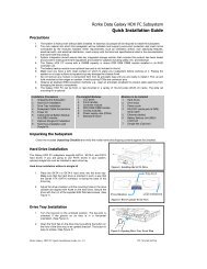
Safety Precautions<br />
Precautions <strong>and</strong> Instructions<br />
• Prior to powering on the subsystem, ensure that the correct power range is being<br />
used.<br />
• The GALAXY subsystem comes with sixteen (16) drive bays. Leaving any of<br />
these drive bays empty will greatly affect the efficiency of the airflow within the<br />
enclosure, <strong>and</strong> will consequently lead to the system overheating, which can<br />
cause irreparable damage.<br />
• If a module fails, leave it in place until you have a replacement unit <strong>and</strong> you are<br />
ready to replace it.<br />
• Airflow Consideration: The subsystem requires an airflow clearance, especially<br />
at the front <strong>and</strong> rear.<br />
• H<strong>and</strong>le subsystem modules using the retention screws, eject levers, <strong>and</strong> the metal<br />
frames/face plates. Avoid touching PCB boards <strong>and</strong> connector pins.<br />
• To comply with safety, emission, or thermal requirements, none of the covers or<br />
replaceable modules should be removed. Make sure that during operation, all<br />
enclosure modules <strong>and</strong> covers are securely in place.<br />
• Be sure that the rack cabinet into which the subsystem chassis will be installed<br />
provides sufficient ventilation channels <strong>and</strong> airflow circulation around the<br />
subsystem.<br />
• Provide a soft, clean surface to place your subsystem on before working on it.<br />
Servicing on a rough surface may damage the exterior of the chassis.<br />
• If it is necessary to transport the subsystem, repackage all disk drives separately.<br />
• Dual redundant controller models come with two controller modules that must<br />
be installed into the subsystem. Single controller modules come with a single<br />
controller module <strong>and</strong> a metal sheet is placed over the lower controller bay at the<br />
rear of the subsystem. Since single controller modules cannot be upgraded, this<br />
metal sheet should NEVER be removed.<br />
ix
<strong>Galaxy</strong> <strong>Raid</strong> <strong>Installation</strong> <strong>and</strong> <strong>Hardware</strong> <strong>Reference</strong> Manual<br />
x<br />
ESD Precautions<br />
About This Manual<br />
Observe all conventional anti-ESD methods while h<strong>and</strong>ling system<br />
modules. The use of a grounded wrist strap <strong>and</strong> an anti-static work pad are<br />
recommended. Avoid dust <strong>and</strong> debris in your work area.<br />
This manual:<br />
Revision History<br />
• Introduces the GALAXY RAID subsystem series.<br />
• Describes all the active components in the subsystem.<br />
• Provides recommendations <strong>and</strong> details about the hardware installation<br />
process.<br />
• Briefly describes how to monitor the subsystem.<br />
• Describes how to maintain the subsystem.<br />
This manual does not:<br />
• Describe components that are not user-serviceable.<br />
• Describe the configuration options of firmware, using terminal<br />
emulation programs, or the RAIDWatch GUI software that came with<br />
your subsystem.<br />
• Give a detailed description of the RAID controllers embedded within<br />
the subsystem.<br />
♦ Initial release<br />
Who should read this manual?<br />
This manual assumes that its readers are experienced with computer<br />
hardware installation <strong>and</strong> are familiar with storage enclosures.
Related Documentation<br />
Conventions<br />
Naming<br />
Lists<br />
• User’s Operation Manual<br />
<strong>Galaxy</strong> <strong>Raid</strong> <strong>Installation</strong> <strong>and</strong> <strong>Hardware</strong> <strong>Reference</strong> Manual<br />
• RAIDWatch User’s Manual<br />
These two documents can be found in the product utility CD included with<br />
your subsystem package.<br />
From this point on <strong>and</strong> throughout the rest of this manual, the GALAXY<br />
series is referred to as simply the “subsystem” or the “system” <strong>and</strong><br />
GALAXY is frequently abbreviated as “GAL.”<br />
Bulleted Lists: Bulleted lists are statements of non-sequential facts. They<br />
can be read in any order. Each statement is preceded by a round black dot<br />
“•.”<br />
Numbered Lists: Numbered lists are used to describe sequential steps you<br />
should follow in order.<br />
Important information that users should be aware of is indicated with the<br />
following icons:<br />
NOTE:<br />
These messages inform the reader of essential but non-critical<br />
information. These messages should be read carefully as any directions<br />
or instructions contained therein can help you avoid making mistakes.<br />
CAUTION!<br />
Cautionary messages should also be heeded to help you reduce the<br />
chance of losing data or damaging the system.<br />
IMPORTANT!<br />
The Important messages pertain to use the GALAXY subsystem<br />
introduced in this manual.<br />
xi
<strong>Galaxy</strong> <strong>Raid</strong> <strong>Installation</strong> <strong>and</strong> <strong>Hardware</strong> <strong>Reference</strong> Manual<br />
xii<br />
WARNING!<br />
Warnings appear where overlooked details may cause damage to the<br />
equipment or result in personal injury. Warnings should be taken<br />
seriously.<br />
Software <strong>and</strong> Firmware Updates<br />
Please contact <strong>Rorke</strong> <strong>Data</strong>’s tech support (techsupport@rorke.com) for the<br />
latest software or firmware updates.<br />
Problems that occur during the updating process may cause unrecoverable<br />
errors <strong>and</strong> system down time. Always consult technical personnel before<br />
proceeding with any firmware upgrade.<br />
NOTE:<br />
The firmware version installed on your system should provide the<br />
complete functionality listed in the specification sheet/user’s manual.<br />
We provide special revisions for various application purposes.<br />
Therefore, DO NOT upgrade your firmware unless you fully underst<strong>and</strong><br />
what a firmware revision will do.
1.1. Product Overview<br />
1.1.1 Product Introduction<br />
Chapter 1: Introduction<br />
Chapter 1<br />
Introduction<br />
This hardware manual briefly introduces the single controller <strong>Galaxy</strong> A16F-G2221<br />
sixteen-bay Fibre Channel (FC)-to-Serial ATA (SATA) RAID subsystem shown in<br />
Figure 1-1.<br />
Figure 1-1: <strong>Galaxy</strong> 16-bay SATA RAID Subsystem<br />
The A16F-G2221 RAID subsystems come with one (1) FC-to-SATA RAID controller.<br />
The controller has two (2) 2Gbps (FC-2G) host channels that are routed to two (2)<br />
external small form-factor pluggable (SFP) connectors (one per channel). Two (2)<br />
onboard SATA chips provide sixteen (16) 3.0Gbps SATA II drive channels that can<br />
support up to sixteen (16) SATA II hard drives. The controller board has a pre-installed<br />
256MB DDR RAM DIMM module <strong>and</strong> can support a memory module with a capacity up<br />
to 1GB. The metal container in which the RAID controller is pre-installed is referred to<br />
as the “controller module.”<br />
The controller module is accessed through the rear of the A16F-G2221 subsystem. Two<br />
(2) small SFP connectors on the rear panel of the controller module connect the enclosure<br />
to external FC-2G host computers. Two (2) RS-232C (audio jack) serial port connectors<br />
are located on the rear panel of each controller module. One serial port (COM1) enables<br />
serial communication between the controller <strong>and</strong> an external PC running a pre-installed<br />
terminal emulation program that can be used to configure <strong>and</strong> manage the RAID<br />
subsystem. The second serial port (COM2) can be used for uninterruptible power supply<br />
Product Overview 1-1
<strong>Galaxy</strong> A16F-G2221 <strong>Installation</strong> <strong>and</strong> <strong>Hardware</strong> <strong>Reference</strong> Manual<br />
(UPS) support. (See Appendix B) A RJ-45 Ethernet connector allows for web-based<br />
management of the subsystem.<br />
I/O signals/comm<strong>and</strong>s transmitted between the controller <strong>and</strong> the drives at the front of the<br />
subsystem pass through non-user-serviceable back-plane board. The back-plane is<br />
connected to a maximum of sixteen (16) hard drives that you purchase separately <strong>and</strong><br />
install into the sixteen (16) drive trays that come with the subsystem. The drive trays,<br />
which must be installed in the drive bays, accommodate SATA II (backward compatible<br />
to SATA I) or parallel ATA (PATA) hard drives.<br />
Two (2), redundant, hot-swappable, dual-fan cooling modules protect the RAID<br />
subsystem from overheating <strong>and</strong> two (2), redundant, hot-swappable, 2U 460W power<br />
supply unit (PSU) modules provide constant power to the RAID subsystem. The modular<br />
nature of the RAID subsystem <strong>and</strong> the easy accessibility to all major components ensures<br />
that the A16F-G2221 can be easily <strong>and</strong> efficiently operated <strong>and</strong> maintained.<br />
1.1.2 Enclosure Chassis<br />
1.1.2.1 Chassis Overview<br />
The A16F-G2221 subsystem enclosure is a 3U metal chassis. The back-plane board<br />
divides the enclosure internally into front <strong>and</strong> rear sections. (See Figure 1-2) The front<br />
section accommodates sixteen (16) drive trays (with their associated hard drives) <strong>and</strong> the<br />
rear section accommodates two (2) PSU modules, two (2) dual-fan cooling modules, <strong>and</strong><br />
one (1) RAID controller module. The two (2) h<strong>and</strong>les on the front of the subsystem<br />
enable you to easily insert/extract the chassis into/from a rack or cabinet. Pre-drilled<br />
mounting holes in the sides of the 3U RAID subsystem enclosure allow you to attach<br />
separately purchased slide rails so that you can install the enclosure into a rack or cabinet.<br />
1-2 Product Overview
Figure 1-2: <strong>Galaxy</strong> 16-bay SATA RAID Subsystem Overview<br />
Chapter 1: Introduction<br />
CAUTION!<br />
When working with the subsystem, it is important to use tools with extreme care. Do<br />
not place tools or other items on top of the enclosure to help avoid damaging the<br />
outward appearance of the chassis.<br />
1.1.2.2 Physical Dimensions<br />
The A16F-G2221 subsystem comes in a st<strong>and</strong>ard 3U chassis with the following<br />
dimensions:<br />
Dimensions w/o front h<strong>and</strong>les w/ front h<strong>and</strong>les<br />
Height 130.0mm 131.0mm<br />
Width 445.0mm 482.6mm<br />
Length 488.2mm 504.3mm<br />
Product Overview 1-3
<strong>Galaxy</strong> A16F-G2221 <strong>Installation</strong> <strong>and</strong> <strong>Hardware</strong> <strong>Reference</strong> Manual<br />
1.1.2.3 Front Panel Overview<br />
Figure 1-3: A16F-G2221 RAID Subsystem Front View<br />
As shown in Figure 1-3, the front of the A16F-G2221 subsystems feature a 4 x 4 layout<br />
for sixteen (16) drive trays that are designed to accommodate sixteen (16) st<strong>and</strong>ard 3.5”<br />
SATA II or PATA drives. The front side of the A16F-G2221 RAID subsystem also has<br />
two (2) foldable h<strong>and</strong>les (see Figure 1-3) mounted on the sides. These front h<strong>and</strong>les are<br />
conveniently placed <strong>and</strong> simplify moving the subsystem enclosure into <strong>and</strong> out of a rack<br />
or cabinet. The left side front-h<strong>and</strong>le houses a 16x2 character LCD panel that can be used<br />
for subsystem configuration, troubleshooting <strong>and</strong> status checking.<br />
1.1.2.4 Hard Drive Numbering<br />
The front panel of the A16F-G2221 enclosure houses sixteen (16) hard drives in a 4x4<br />
configuration as shown in Figure1-4. When viewed from the front, the drive bays (slots)<br />
are numbered 1 to 16 from top to bottom, from left to right.<br />
Figure1-4: Hard Drive IDs<br />
1-4 Product Overview
1.1.2.5 Rear Panel Overview<br />
Figure 1-5: A16F-G2221 Rear View<br />
Chapter 1: Introduction<br />
The subsystem’s rear panel is shown in Figure 1-5. The rear panel provides access to all<br />
the components located in the rear section of the RAID subsystem enclosure.<br />
Two (2) redundant, hot-swappable 460W PSU modules, which are accessible through the<br />
rear panel, connect the A16F-G2221 subsystems to main power. A redundant, hotswappable<br />
dual-fan cooling module is located below each PSU module. Two (2) PSU<br />
switches, located directly above the cooling fan modules, activate the PSU modules.<br />
The controller modules, with two (2) SFP ports, two (2) RS-232C (audio jack) serial<br />
ports, one (1) RJ-45 Ethernet connector, <strong>and</strong> status-indicating LEDs, are located in the<br />
center of the rear panel. For single controller models, a metal sheet is placed beneath the<br />
RAID controller module instead of a second controller.<br />
1.1.2.6 Back-plane Board<br />
An integrated back-plane board separates the front <strong>and</strong> rear sections of the A16F-G2221<br />
subsystems. This PCB board provides logic level signals <strong>and</strong> low voltage power paths.<br />
They contain no user-serviceable components.<br />
Product Overview 1-5
<strong>Galaxy</strong> A16F-G2221 <strong>Installation</strong> <strong>and</strong> <strong>Hardware</strong> <strong>Reference</strong> Manual<br />
1.2. A16F-G2221 Subsystem Components<br />
1.2.1 LCD Panel<br />
Figure 1-6: LCD Panel<br />
The LCD panel shown in Figure 1-6 consists of a 16x2 character LCD screen with push<br />
buttons <strong>and</strong> LED status indicators. The LCD front panel provides full access to all RAID<br />
configurations <strong>and</strong> monitoring. After powering up the subsystem, the initial screen will<br />
show the subsystem model name. A different name may be assigned for the system or<br />
different arrays. This will enable easier identification in a topology with numerous arrays.<br />
1-6 A16F-G2221 Subsystem Components
1.2.2 Drive Trays<br />
Part Number: GAL-9273CDTray<br />
Figure 1-7: Drive Tray<br />
Chapter 1: Introduction<br />
Each A16F-G2221 subsystem comes with sixteen (16) drive trays. The front panel of<br />
each drive tray (see Figure 1-7) contains a locking mechanism that secures the drive tray<br />
to the enclosure <strong>and</strong> a latch that facilitates the removal <strong>and</strong> installation of the drive tray.<br />
Two (2) status-indicating LEDs are also located on the front of the drive tray. Retention<br />
screw holes are located on the sides of the drive tray. These holes are reserved for<br />
securing hard drives to the tray. Other retention screw holes are located on the surface of<br />
the tray at the rear.<br />
The drive trays accommodate SATA-II hard drives by default. If you are going to use<br />
PATA drives in the subsystem, separately purchased SATA-to-PATA dongle kits must<br />
be installed.<br />
WARNING!<br />
Be careful not to warp, twist, or contort the drive tray in any way (e.g., by dropping it<br />
or resting heavy objects on it). The drive tray has been customized to fit into the drive<br />
bays in the A16F-G2221 subsystem. If the drive bay superstructure is deformed or<br />
altered, the drive trays may not fit into the drive bay.<br />
1.2.3 SATA-to-PATA Dongle Kits<br />
Part Number: GAL-9270A2N1S1P<br />
A16F-G2221 Subsystem Components 1-7
<strong>Galaxy</strong> A16F-G2221 <strong>Installation</strong> <strong>and</strong> <strong>Hardware</strong> <strong>Reference</strong> Manual<br />
Figure 1-8: SATA-to-PATA Dongle Kit<br />
Separately purchased <strong>and</strong> independently installed SATA-to-PATA dongle kits (see<br />
Figure 1-8) are also available. These dongle kits facilitate the installation of PATA<br />
drives into the drive trays. The dongle kits have a power connector <strong>and</strong> a SATA<br />
connector. These connectors must be connected to the PATA drives at the time of<br />
installation.<br />
WARNING!<br />
The dongle kits are small, delicate components that must be h<strong>and</strong>led with care.<br />
1.2.4 RAID Controller Modules<br />
Part Number: GAL-83AF22GD16-M2 or GAL-83AF22GD16 (without memory)<br />
The RAID controller module contains a main circuit board, a dedicated drive-plane<br />
management interface, <strong>and</strong> a preinstalled 256MB (or above) DDR RAM DIMM module.<br />
The controller module contains no user-serviceable components. Except when replacing<br />
a faulty unit, or installing/upgrading the cache memory inside, the controller module<br />
should never be removed from the subsystem.<br />
WARNING!<br />
Unnecessary tampering with the RAID controller can damage the controller <strong>and</strong> make<br />
the system unusable.<br />
1-8 A16F-G2221 Subsystem Components
Retention<br />
Screws<br />
Status Indicating LEDs<br />
SFP Connectors COM Ports<br />
Chapter 1: Introduction<br />
Levers Levers<br />
Figure1-9: A16F-G2221 RAID Controller Module Rear Panel<br />
Retention<br />
Screws<br />
Ethernet Port<br />
The A16F-G2221 RAID controller module rear panel is shown in Figure1-9 <strong>and</strong> has two<br />
(2) SFP connectors labeled FC-CH0 <strong>and</strong> FC-CH1. Two (2) COM ports (labeled COM1<br />
<strong>and</strong> COM2), one (1) Ethernet connector (next to COM2) <strong>and</strong> eight (8) status-indicating<br />
LEDs (labeled from 1 to 6 <strong>and</strong> from A to B) are also seen on the controller module rear<br />
panel. The controller board is located in the controller module <strong>and</strong> can only be seen after<br />
the controller module has been removed from the subsystem enclosure. The controller<br />
module rear panel has two (2) levers that are used to secure the controller module to the<br />
A16F-G2221 subsystem enclosure. Two (2) retention screws secure the levers to the<br />
controller module.<br />
1.2.5 Controller Module Interfaces<br />
All external interfaces that connect to external devices are located on the controller<br />
module rear panel. The interfaces are listed below.<br />
♦ Host ports: The two (2) SFP cages (labeled FC-CH0 <strong>and</strong> FC-CH1) at the bottom<br />
of the controller module must be connected to external FC-2G host computer(s).<br />
These SFP connectors can auto-negotiate the speed <strong>and</strong> determine whether the data<br />
transmission rate is 1Gbps or 2Gbps.<br />
♦ RS-232C (Audio Jack): All controller modules come with two (2) RS-232C (audio<br />
jack) serial ports. The serial ports can be used for terminal emulation <strong>and</strong><br />
uninterruptible power supply (UPS) support.<br />
♦ Ethernet ports: A single 10/100BaseT Ethernet port (located next to COM2) is<br />
used for remote management through the network.<br />
♦ Drive: All models come with sixteen (16) SATA drive channels that are interfaced<br />
through board-to-board connectors to subsystem back plane. (NOTE: Drive<br />
interfaces are not accessed through the controller module rear panel.)<br />
A16F-G2221 Subsystem Components 1-9
<strong>Galaxy</strong> A16F-G2221 <strong>Installation</strong> <strong>and</strong> <strong>Hardware</strong> <strong>Reference</strong> Manual<br />
1.2.6 DIMM Modules<br />
1.2.7 BBU<br />
The controller module comes with a pre-installed 256MB (or above) DDR RAM DIMM<br />
module. The controller module supports memory modules with sizes from 256MB to<br />
1GB. The DIMM module is located on the controller board.<br />
Part Number: GAL-9273CBT-C<br />
An optional, separately purchased Li-ION battery backup unit (BBU) (see Figure 1-10)<br />
can sustain cache memory after a power failure. If you purchased a BBU, it will be<br />
installed on the upper left side of the controller module in the rear subsystem chassis.<br />
Please refer to Section 2.6 for installation instructions.<br />
Figure 1-10: BBU<br />
In accordance with international transportation regulations, the BBU is only charged to<br />
between 35% <strong>and</strong> 45% of its total capacity when shipped. Therefore, after powering on<br />
the subsystem (see Section 4.2) the BBU must be charged to its full capacity. It normally<br />
requires approximately twelve (12) hours for the battery to be fully charged. If the battery<br />
is not fully charged after twelve (12) hours, there is a problem with the BBU <strong>and</strong> you<br />
should contact your subsystem vendor immediately. While the battery is being charged,<br />
the LED on the BBU rear panel <strong>and</strong> the fGalh LED on the rear panel of the controller<br />
module will flash slowly. (See Chapter 3.2.8 for details on the LED indicators.) You can<br />
check the status of the battery’s charge via RAIDWatch or the firmware.<br />
1.2.8 Power Supply Units<br />
Part Number: GAL-9273CPSU<br />
1-10 A16F-G2221 Subsystem Components
Figure1-11: PSU Module<br />
Chapter 1: Introduction<br />
The A16F-G2221 is equipped with two (2) redundant, hot-swappable, 460W PSUs,<br />
which are located at the rear of the enclosure. (See Figure 1-5) The PSU is permanently<br />
mounted into a 2U (dual-level) bracket especially designed to house both the PSU <strong>and</strong> a<br />
cooling module, which is mounted in the lower part of the 2U bracket. Hot-swapping the<br />
PSU requires the removal of the cooling module.<br />
As shown in Figure1-11, each PSU comes with a single power socket for power cord<br />
plug-in, <strong>and</strong> a power switch on the right to turn the subsystem on <strong>and</strong> off. Two (2)<br />
embedded cooling fans provide sufficient airflow to keep the PSU cool. A single LED<br />
indicates the PSU status. When any power supply failure occurs, such as over-voltage or<br />
fan failure, the LED shines red. A h<strong>and</strong>le at the back of the PSU has been especially<br />
designed to enable you to remove the PSU from the subsystem while the subsystem is<br />
online. This should only be done if the PSU has failed <strong>and</strong> needs to be replaced.<br />
A retention screw at the top of the PSU module secures the PSU to the enclosure. To<br />
remove the PSU, the retention screw must be removed first. When installing a new PSU<br />
module, make sure that the retention screw has been firmly secured.<br />
PSU specifications are shown in Appendix B.<br />
1.2.9 Cooling Modules<br />
Part Number: GAL-9273CFanMod<br />
A16F-G2221 subsystems come with two (2) hot-swappable, redundant, dual-fan cooling<br />
modules (shown in Figure 1-12) pre-installed in the subsystem. Two (2) 9.7cm blowers<br />
are housed in each cooling module <strong>and</strong> provide a total of 61 CFM of airflow running at<br />
the high-level speed. These modules generate a cooling airflow from the front to the rear<br />
of the subsystem, extracting the heat generated by the SATA or PATA hard drives. The<br />
two (2) cooling fan modules are installed directly below the PSU modules (see Figure<br />
1-5) in the bracket that is attached to the PSU module.<br />
A16F-G2221 Subsystem Components 1-11
<strong>Galaxy</strong> A16F-G2221 <strong>Installation</strong> <strong>and</strong> <strong>Hardware</strong> <strong>Reference</strong> Manual<br />
The cooling fans also operate at two different speeds following firmware control. The<br />
cooling fans operate at a higher speed when one of the critical components, e.g., a PSU,<br />
has failed or when the higher thresholds on temperature are violated.<br />
Figure 1-12: Bottom View of a Dual-fan Cooling Module<br />
1.3. Subsystem Monitoring<br />
The A16F-G2221 RAID subsystem comes with several monitoring methods to give you<br />
constant updates on the status of the system <strong>and</strong> individual components. The following<br />
monitoring features are included in the subsystem.<br />
1.3.1 I 2 C bus<br />
The following A16F-G2221 elements interface to the RAID controller over a non-user -<br />
serviceable I2C bus:<br />
♦ Power supply status<br />
♦ Cooling module<br />
♦ Temperature sensors on backplane <strong>and</strong> within the RAID controller module<br />
1.3.2 LED Indicators<br />
The following active components all come with LEDs that indicate the status of the<br />
individual component:<br />
♦ RAID controller (9 LEDs)<br />
♦ BBU (1 LED)<br />
♦ LCD panel (3 LEDs)<br />
1-12 Subsystem Monitoring
♦ Cooling module (2 LEDs)<br />
♦ PSU module (1 LED)<br />
♦ Drive trays (2 LEDs)<br />
1.3.3 Firmware <strong>and</strong> RAIDWatch GUI<br />
Chapter 1: Introduction<br />
Firmware: The firmware is pre-installed software used to configure the subsystem. The<br />
latest firmware functionalities include Task Scheduler, Intelligent Drive H<strong>and</strong>ling, <strong>and</strong><br />
Media Scan. Media Scan h<strong>and</strong>les low quality drives in both the degraded mode <strong>and</strong><br />
during the rebuild process. Maintenance tasks will then be performed on an entire array<br />
or specific hard drives. Various options are user-configurable such as priority, start time,<br />
<strong>and</strong> execution internals. For more information, please refer to the Generic Manual in the<br />
product CD.<br />
RAIDWatch: RAIDWatch is a premier web-based graphics user interface (GUI) that can<br />
be installed on a remote computer <strong>and</strong> accessed via the web. The manager communicates<br />
with the array via the connection of the existing host interface or Ethernet link to the<br />
array’s LAN port. For more information, please refer to the RAIDWatch User’s Manual<br />
in the product CD.<br />
1.3.4 Audible Alarms<br />
The A16F-G2221 subsystem comes with audible alarms that are triggered when certain<br />
active components fail or when certain controller or subsystem thresholds are exceeded.<br />
When you hear an audible alarm emitted from the A16F-G2221 subsystem, it is<br />
imperative that you determine the cause <strong>and</strong> rectify the problem immediately.<br />
WARNING!<br />
Failing to respond when an audible alarm is heard can lead to permanent damage of<br />
the A16F-G2221 subsystem. When an audible alarm is heard, rectify the problem as<br />
soon as possible.<br />
1.4. Hot-swappable Components<br />
1.4.1 Hot-swap Capabilities<br />
The A16F-G2221 subsystem comes with a number of hot-swappable components. A hotswap<br />
component is one that can be exchanged while the subsystem is still online without<br />
affecting the operational integrity of the subsystem. These components should only be<br />
removed from the subsystem when they are being replaced. At no other time should these<br />
components be removed from the subsystem.<br />
Hot-swappable Components 1-13
<strong>Galaxy</strong> A16F-G2221 <strong>Installation</strong> <strong>and</strong> <strong>Hardware</strong> <strong>Reference</strong> Manual<br />
1.4.2 Components<br />
The following components are all hot-swappable:<br />
♦ PSU modules<br />
♦ Cooling modules<br />
♦ Battery backup module<br />
♦ Hard drives<br />
NOTE:<br />
Instructions on how to replace these hot-swappable are given in Chapter 5.<br />
1.4.3 Normalized Airflow<br />
Proper subsystem cooling is referred to as “normalized” airflow. Normalized airflow<br />
ensures the sufficient cooling of the subsystem <strong>and</strong> is only attained when all the<br />
components are properly installed. Therefore, a failed component should only be hotswapped<br />
when a replacement is available. If a failed component is removed but not<br />
replaced, permanent damage to the subsystem can result.<br />
1-14 Hot-swappable Components
Chapter 1: Introduction<br />
Chapter 1 Introduction.............................................................. 1-1<br />
1.1. Product Overview........................................................................................................................ 1-1<br />
1.1.1 Product Introduction ............................................................................................................1-1<br />
1.1.2 Enclosure Chassis................................................................................................................ 1-2<br />
1.1.2.1 Chassis Overview ............................................................................................................ 1-2<br />
1.1.2.2 Physical Dimensions........................................................................................................ 1-3<br />
1.1.2.3 Front Panel Overview...................................................................................................... 1-4<br />
1.1.2.4 Hard Drive Numbering.................................................................................................... 1-4<br />
1.1.2.5 Rear Panel Overview ....................................................................................................... 1-5<br />
1.1.2.6 Back-plane Board ............................................................................................................ 1-5<br />
1.2. A16F-G2221 Subsystem Components.......................................................................................... 1-6<br />
1.2.1 LCD Panel ........................................................................................................................... 1-6<br />
1.2.2 Drive Trays.......................................................................................................................... 1-7<br />
1.2.3 SATA-to-PATA Dongle Kits .............................................................................................. 1-7<br />
1.2.4 RAID Controller Modules ................................................................................................... 1-8<br />
1.2.5 Controller Module Interfaces............................................................................................... 1-9<br />
1.2.6 DIMM Modules................................................................................................................. 1-10<br />
1.2.7 BBU................................................................................................................................... 1-10<br />
1.2.8 Power Supply Units........................................................................................................... 1-10<br />
1.2.9 Cooling Modules ............................................................................................................... 1-11<br />
1.3. Subsystem Monitoring ............................................................................................................... 1-12<br />
1.3.1 I 2 C bus............................................................................................................................... 1-12<br />
1.3.2 LED Indicators ..................................................................................................................1-12<br />
1.3.3 Firmware <strong>and</strong> RAIDWatch GUI.................................................................................... 1-13<br />
1.3.4 Audible Alarms..................................................................................................................1-13<br />
1.4. Hot-swappable Components...................................................................................................... 1-13<br />
1.4.1 Hot-swap Capabilities........................................................................................................ 1-13<br />
1.4.2 Components....................................................................................................................... 1-14<br />
1.4.3 Normalized Airflow........................................................................................................... 1-14<br />
Hot-swappable Components 1-15
<strong>Galaxy</strong> A16F-G2221 <strong>Installation</strong> <strong>and</strong> <strong>Hardware</strong> <strong>Reference</strong> Manual<br />
audible alarm, 1-13<br />
auto-negotiate, speed, 1-9<br />
BBU, 1-10<br />
chassis, 1-2~3<br />
COM1, 1-9<br />
COM2, 1-9<br />
configuration, 1-4<br />
controller module, 1-1~2, 1-5, 1-8~9<br />
cooling fan module, 1-11<br />
cooling module, 1-2, 1-5<br />
dimensions, 1-3<br />
DIMM module, 1-10<br />
dongle kits, 1-8<br />
drive channel, 1-9<br />
drive ID, 1-5<br />
drive tray, 1-2, 1-4<br />
drive tray front panel, 1-7<br />
drive tray LEDs, 1-7<br />
drive trays, 1-7<br />
drive-plane, 1-5, 1-8<br />
dual fan cooling module, 1-11<br />
dual-fan cooling module, 1-2, 1-5<br />
Dual-fan cooling module, 1-12<br />
dual-redundant controller, 1-1<br />
dummy controller canister, 1-5<br />
Ethernet port, 1-9<br />
external interfaces, 1-9<br />
firmware, 1-13<br />
front section, 1-2<br />
GUI, 1-13<br />
h<strong>and</strong>le, 1-2, 1-4<br />
hard drive, 1-2<br />
host channel, 1-1<br />
host computer, 1-1, 1-9<br />
hot-swappable components, 1-13<br />
I 2 C bus, 1-12<br />
initial screen, 1-6<br />
interfaces, external, 1-9<br />
LCD panel, 1-4, 1-6<br />
LCD screen, 1-6<br />
LED status indicators, 1-6<br />
memory module, 1-8<br />
mid-plane, 1-1~2<br />
monitoring methods, 1-12<br />
normalized airflow, 1-14<br />
numbering of drive trays, 1-4<br />
PATA hard drive, 1-2, 1-4<br />
PATA hard drives, 1-8<br />
power cord, 1-11<br />
power socket, 1-11<br />
power supply unit, 1-2<br />
power switch, 1-11<br />
PSU cooling fans, 1-11<br />
PSU module, 1-2, 1-5, 1-12<br />
PSU switch, 1-5<br />
RAIDWatch, 1-13<br />
rear panel, 1-5<br />
rear section, 1-2<br />
RJ-45 Ethernet connector, 1-1, 1-5, 1-9<br />
RS-232C, 1-1, 1-5, 1-9<br />
SATA chip, 1-1<br />
SATA hard drive, 1-2, 1-4<br />
SATA-to-PATA dongle kits, 1-8<br />
serial port, 1-1, 1-5, 1-9<br />
SFP connector, 1-1<br />
SFP module, 1-5, 1-9<br />
single controller, 1-1<br />
single controller subsystem, 1-5<br />
slide rail, 1-2, 1-6<br />
status checking, 1-4<br />
status indicating LEDs, 1-5, 1-12<br />
status-indicating LEDs, 1-9<br />
terminal emulation, 1-1, 1-9<br />
terminal emulation program, 1-13<br />
troubleshooting, 1-4<br />
uninterruptible power supply, 1-9<br />
UPS support, 1-1, 1-9<br />
1-16 Hot-swappable Components
2.1. <strong>Installation</strong> Overview<br />
Chapter 2: <strong>Hardware</strong> <strong>Installation</strong><br />
Chapter 2<br />
<strong>Hardware</strong> <strong>Installation</strong><br />
This chapter gives detailed instructions on how to install the A16F-G2221 subsystem.<br />
When installing the subsystem, it is necessary to install the hard drives <strong>and</strong> drive trays.<br />
Depending on the type of drives being used; it may also be necessary to install the dongle<br />
kits. <strong>Installation</strong> into a rack or cabinet should occur before the hard drives or drive trays<br />
are installed into the subsystem. It is also advisable to confirm that all of the components<br />
listed on the printed unpacking list that came with the subsystem were indeed shipped<br />
with it.<br />
CAUTION!<br />
Please note that the installation instructions described in this manual should be<br />
carefully followed in order to avoid damage to the system.<br />
2.2. <strong>Installation</strong> Pre-requisites<br />
1. Static-free installation environment: The A16F-G2221 subsystem must be installed<br />
in a static-free environment to minimize the possibility of electrostatic discharge<br />
(ESD) damage. (See Section 2.3)<br />
2. Component check: Before installing the A16F-G2221 subsystem, you should<br />
confirm that you have received all of the required components by checking the<br />
package contents against the Unpacking List.<br />
3. Memory modules: If you wish to change the pre-installed memory modules, the<br />
separately purchased modules must be installed.<br />
4. Hard drives: SATA-II hard drives have been pre-integrated <strong>and</strong> tested. Use this<br />
section to replace a faulty drive.(See Section 2.6)<br />
5. SFP transceivers: If the FC cables that were previously purchased do not come with<br />
pre-installed SFP transceivers, transceivers must be separately purchased <strong>and</strong><br />
connected to the FC cables. (See Section 4.2.3)<br />
6. Cabling: All the FC cables that connect the A16F-G2221 subsystem to the host must<br />
be purchased separately. (See Section 4.2.1)<br />
<strong>Installation</strong> Overview 2-1
<strong>Galaxy</strong> A16F-G2221 <strong>Installation</strong> <strong>and</strong> <strong>Hardware</strong> <strong>Reference</strong> Manual<br />
2.3. Safety Precautions:<br />
2.3.1 Precautions <strong>and</strong> Instructions<br />
1. Be sure the correct power range (100~120 or 200~230VAC) is supplied by your rack<br />
cabinet or power outlet.<br />
2. Thermal notice: All drive trays (even if they do not contain a hard drive) must be<br />
installed into the enclosure. Leaving a drive bay or module slot open will greatly<br />
affect the efficiency of airflow within the enclosure, <strong>and</strong> will consequently lead to<br />
system overheating. Keep a faulty module in place until you have a replacement unit<br />
<strong>and</strong> you are ready to replace it.<br />
3. An enclosure without disk drives can weigh over 24 kilograms. Two (2) people will<br />
be required to install or relocate the subsystem. Drives should be removed from the<br />
enclosure before moving the subsystem.<br />
4. Airflow considerations: The subsystem requires an airflow clearance especially on<br />
the front <strong>and</strong> on the rear. A minimum of 2.5cm is required between the front of the<br />
enclosure <strong>and</strong> rack cover. A minimum of 5cm is required between the enclosure <strong>and</strong><br />
the end of the rack for proper ventilation.<br />
5. H<strong>and</strong>le the system modules by the retention screws, eject levers, or the module’s<br />
metal frame/face plate only. Avoid touching the PCB boards or connector pins.<br />
6. None of the covers or replaceable modules should be removed in order to maintain<br />
compliance with safety, emission, or thermal requirements.<br />
7. Always secure every enclosure module by its retaining screws or make sure it is held<br />
in place by its latches.<br />
8. Always make sure the subsystem has a safe electrical earth connection via power<br />
cords or chassis ground by the rack cabinet.<br />
9. Be sure that the rack cabinet in which the subsystem chassis is to be installed<br />
provides sufficient ventilation channels <strong>and</strong> airflow circulation around the<br />
subsystem.<br />
10. Provide a soft, clean surface to place your enclosure on before working on it.<br />
Servicing the enclosure on a rough surface may damage the finish of the chassis.<br />
11. If it is necessary to transport the subsystem, repackage all drives <strong>and</strong> replaceable<br />
modules separately.<br />
2.3.2 Static-free <strong>Installation</strong><br />
Static electricity can damage the electronic components of the system. Most of the<br />
controllers that are returned for repair are the result of improper installation <strong>and</strong> ESD<br />
2-2 Safety Precautions:
Chapter 2: <strong>Hardware</strong> <strong>Installation</strong><br />
damage. To prevent ESD damage, follow these precautions before touching or h<strong>and</strong>ling<br />
any of the components:<br />
♦ When installing the A16F-G2221, you should wear an anti-static wrist b<strong>and</strong> or touch<br />
a grounded metal surface to discharge any static electricity from your body.<br />
♦ Avoid carpets, plastic, vinyl, <strong>and</strong> styrofoam in the work area.<br />
♦ H<strong>and</strong>le all components by holding their edges or metal frame. Avoid touching PCB<br />
boards or connector pins.<br />
2.4. General <strong>Installation</strong> Procedure<br />
Detailed, illustrated instructions for each step are given in the following sections.<br />
CAUTION!<br />
To ensure that the system is correctly installed, please follow the steps outlined below.<br />
If these steps are followed, the installation will be fast <strong>and</strong> efficient. If these steps are<br />
not followed, the hardware may accidentally be installed incorrectly.<br />
Step 1. Unpack. Unpack the subsystem <strong>and</strong> make sure that all the required subsystem<br />
components have indeed arrived. (See Section 2.5)<br />
Step 2. Rack/Cabinet installation. If the A16F-G2221 is going to be installed in a<br />
rack or a cabinet, it should be installed prior to the installation of the hard<br />
drives. Installing the A16F-G2221 into a rack or cabinet requires at least three<br />
people.<br />
Step 3. Install the dongle kits. If PATA hard drives are going to be used in the<br />
subsystem, separately purchased SATA-to-PATA dongle kits. (See Section<br />
2.7.4)<br />
Step 4. Install hard drives. Separately purchased SATA or PATA hard drives must be<br />
individually installed into the drive trays. (See Section 2.7)<br />
Step 5. Install drive trays. After the hard drives have been installed into the drive<br />
trays, the drive trays must be installed into the enclosure itself. (See Section<br />
2.8)<br />
Step 6. Connect the cables. Use the supplied power cables to connect the subsystem<br />
to main power. Use separately purchased FC cables <strong>and</strong> SFP transceivers to<br />
connect the host ports to the host computers. (See Chapter 4)<br />
Step 7. Power up. Once all of the components have been properly installed <strong>and</strong> all the<br />
cables properly connected, the subsystem can be powered up <strong>and</strong> the RAID<br />
array configured. (See Chapter 4)<br />
General <strong>Installation</strong> Procedure 2-3
<strong>Galaxy</strong> A16F-G2221 <strong>Installation</strong> <strong>and</strong> <strong>Hardware</strong> <strong>Reference</strong> Manual<br />
2.4.1 <strong>Installation</strong> Procedure Flowchart<br />
Figure 2-1 shows a flowchart of the installation procedure. As you complete each step,<br />
check off the “Done” box on the right. Please use this flowchart in conjunction with the<br />
instructions that follow.<br />
Figure 2-1: Upgrade Procedure Flowchart<br />
2.5. Unpacking the Subsystem<br />
The A16F-G2221 subsystem components are packed in several boxes.<br />
WARNING!<br />
Do not rely on the non-definitive, summarized unpacking list shown below--it is for<br />
reference only. A detailed packing list can be found in your product shipping package<br />
or product CD.<br />
Each packed box is separated into upper <strong>and</strong> lower levels.<br />
Upper level: The foam packages on the upper level contain:<br />
• Sixteen (16) drive trays<br />
Lower level: Three boxes are place in the lower level. One box contains the enclosure<br />
chassis with all the pre-installed components. Another two boxes contain power cores<br />
<strong>and</strong> accessory items.<br />
2-4 Unpacking the Subsystem
Chapter 2: <strong>Hardware</strong> <strong>Installation</strong><br />
The enclosure chassis, with its pre-installed components, is located at the bottom of the<br />
package. The pre-installed components include:<br />
♦ One (1) controller module<br />
♦ Two (2) PSU modules<br />
♦ Two (2) cooling modules<br />
♦ Two (2) front h<strong>and</strong>les<br />
♦ One (1) LCD panel pre-installed on the front h<strong>and</strong>le on the left of the enclosure<br />
♦ One (1) backplane board<br />
For a complete <strong>and</strong> detailed unpacking list, please refer to Appendix C.<br />
2.6. Installing the Optional BBU<br />
2.6.1 BBU <strong>Installation</strong> Overview<br />
The BBU is an optional item that can sustain cache memory in the event of a power<br />
failure or in the extremely unlikely event of both PSUs failing. Purchasing <strong>and</strong> installing<br />
a BBU is highly recommended. The optional BBU provides additional data security <strong>and</strong><br />
helps minimize the loss of data during power shutdowns.<br />
The BBU is inserted into the subsystem in the top, left corner of the controller module.<br />
The BBU is secured to the subsystem with two (2) retention screws. When shipped, the<br />
BBU slot in the subsystem rear panel is covered with a metal dummy plate that must first<br />
be removed.<br />
2.6.2 BBU Warnings <strong>and</strong> Precautions<br />
• Install or replace the BBU supplied by your subsystem vendors only. Use of<br />
battery cells provided otherwise will void our warranty.<br />
• Always dispose of discharged or used batteries in an ecologically responsible<br />
manner. Dispose used BBU at authorized battery disposal sites only.<br />
• Do not use nor leave the BBU near a heat source. Heat can melt the insulation<br />
<strong>and</strong> damage other safety features of battery cells, possibly leading it to acid leak,<br />
<strong>and</strong> result in flames or explosion.<br />
• Do not immerse the BBU in water nor allow it to get wet. Its protective features<br />
can be damaged. Abnormal chemical reactions may occur, possibly causing<br />
functional defects, acid leak, <strong>and</strong> other hazardous results.<br />
Installing the Optional BBU 2-5
<strong>Galaxy</strong> A16F-G2221 <strong>Installation</strong> <strong>and</strong> <strong>Hardware</strong> <strong>Reference</strong> Manual<br />
• Do not disassemble or modify the BBU. If disassembled, the BBU could leak<br />
acid, overheat, emit smoke, burst <strong>and</strong>/or ignite.<br />
• Do not pierce the BBU with a sharp object, strike it with a hammer, step on it, or<br />
throw it. These actions could damage or deform it, internal short-circuiting can<br />
occur, possibly causing functional defects, acid leak, <strong>and</strong> other hazardous<br />
results.<br />
• If the BBU leaks, gives off a bad odor, generates heat, becomes discolored or<br />
deformed, or in any way appears abnormal during use, recharging or storage,<br />
immediately remove it from the subsystem <strong>and</strong> stop using it. If this is discovered<br />
when you first use the BBU, return it to your system vendor.<br />
2.6.3 <strong>Installation</strong> Procedure<br />
To install the BBU into the controller module, please follow these steps:<br />
NOTE:<br />
A new or replaced BBU takes 6 hours to charge to its full capacity. Reset the<br />
subsystem whenever a BBU is replaced or added for the new BBU to take effect.<br />
Step 1. Remove the metal sheet from the chassis. A metal sheet covers the BBU slot<br />
on the rear panel of the subsystem. The metal sheet is attached to the chassis<br />
with two (2) screws. These screws must be removed. To loosen, turn the<br />
screws counterclockwise. (See Figure 2-2)<br />
Figure 2-2: Remove the Metal Sheet Retention Screws<br />
Step 2. Remove the metal sheet. It may be difficult to remove the metal sheet as it is<br />
embedded in the subsystem chassis. If you are unable to dislodge the sheet,<br />
wedge the head of a flat-head screwdriver between the metal sheet <strong>and</strong> the<br />
chassis <strong>and</strong> then gently nudge the metal sheet out of the chassis.<br />
2-6 Installing the Optional BBU
Figure 2-3: Use a Screwdriver to Remove the Metal Sheet<br />
Chapter 2: <strong>Hardware</strong> <strong>Installation</strong><br />
Step 3. Install the BBU. After the metal sheet covering the BBU slot has been<br />
removed, the BBU can be installed. To do this, align the BBU with the slot<br />
from which the metal sheet was removed, <strong>and</strong> then gently push the BBU into<br />
the slot. (See Figure 2-4)<br />
Figure 2-4: Install the BBU<br />
Step 4. Secure the BBU to the enclosure. Tighten the two (2) retention screws on the<br />
back of the BBU. The BBU comes equipped with a charger circuit. Once the<br />
BBU is properly installed, the installation process is completed.<br />
Installing the Optional BBU 2-7
<strong>Galaxy</strong> A16F-G2221 <strong>Installation</strong> <strong>and</strong> <strong>Hardware</strong> <strong>Reference</strong> Manual<br />
2.7. Hard Drive <strong>Installation</strong><br />
NOTE:<br />
SATA hard drives have been pre-integrated <strong>and</strong> tested in the drive trays for your<br />
<strong>Galaxy</strong> <strong>Raid</strong>. Use the following procedures to replace faulty hard drives.<br />
2.7.1 Hard Drive <strong>Installation</strong> Overview<br />
WARNING!<br />
1. Hard drives are very delicate <strong>and</strong> must be h<strong>and</strong>led with extreme care. Dropping<br />
onto a hard surface (even over a short distance), hitting, or touching the drive<br />
circuits with your tools may all cause damage to the drives.<br />
2. Observe all ESD prevention methods when installing drives.<br />
The A16F-G2221 supports both SATA <strong>and</strong> PATA hard drives. By default, the drive trays<br />
support SATA hard drives. If you wish to install PATA drives, SATA-to-PATA dongle<br />
kits must be separately purchased <strong>and</strong> independently installed.<br />
2.7.2 Hard Drive <strong>Installation</strong> Prerequisites<br />
NOTE:<br />
The hard drive <strong>and</strong> drive trays should only be installed into the subsystem after the<br />
subsystem has been placed in the desired tower or desktop configuration. If the hard<br />
drives are installed first, the subsystem may be too heavy to maneuver<br />
Hard drives for the A16F-G2221 subsystem must be purchased separately. When<br />
purchasing the hard drives, the following factors must be considered:<br />
Capacity (MB/GB): Use drives with the same capacity. RAID arrays use a “leastcommon-denominator”<br />
approach. The maximum capacity of each drive used in the array<br />
is the maximum capacity of the smallest drive.<br />
Profile: The drive trays <strong>and</strong> bays of the system are designed for 3.5-inch wide x 1-inch<br />
high hard drives. Never use drives of any other size.<br />
Drive type: The A16F-G2221 subsystem can use SATA-I, SATA-II, or PATA hard<br />
drives. Please ensure that you purchase the correct hard drives.<br />
2.7.3 SATA Drive <strong>Installation</strong><br />
SATA drives can be immediately installed into the drive trays.<br />
2-8 Hard Drive <strong>Installation</strong>
Chapter 2: <strong>Hardware</strong> <strong>Installation</strong><br />
Step 1. Correctly orient the hard drive. Prior to installing the hard drive into the drive<br />
tray, make sure that the connector at the back of the drive is facing the back of<br />
the drive tray.<br />
Step 2. Insert the hard drive. Place the hard drive gently into the drive tray. (See<br />
Figure 2-5)<br />
Step 3. Insert retention screws. After the drive has been properly placed into the drive<br />
tray, insert four (4) retention screws to ensure the drive’s secure installation.<br />
(See Figure 2-5)<br />
Figure 2-5: Insert the Hard Drive <strong>and</strong> the Retention Screws<br />
2.7.4 PATA Drive <strong>Installation</strong><br />
If PATA drives will be used in the subsystem, separately purchased SATA-to-PATA<br />
dongle kits (GAL-9270AN1S1P) must be installed.<br />
Step 1. Open the SATA-to-PATA dongle kit. A SATA-to-PATA dongle kit is shown<br />
in Figure 2-6. The dongle kit is mounted onto a metal base plate that has three<br />
(3) pre-drilled holes reserved for retention screws<br />
Hard Drive <strong>Installation</strong> 2-9
<strong>Galaxy</strong> A16F-G2221 <strong>Installation</strong> <strong>and</strong> <strong>Hardware</strong> <strong>Reference</strong> Manual<br />
Figure 2-6: SATA-to-PATA Dongle Kit<br />
Step 2. Locate the drive tray retention screw holes. Three (3) corresponding predrilled<br />
screw holes can be found at the back of the drive tray shown in Figure<br />
2-7.<br />
Figure 2-7: Empty Drive Tray: Dongle Kit Retention Screws<br />
Step 3. Install the dongle kit. Place the dongle kit at the back of the drive tray. Hold<br />
the dongle kit in place <strong>and</strong> turn the drive tray over. Align the holes in the base<br />
of the drive tray with the holes in the dongle kit base tray.<br />
Step 4. Insert the three (3) available retention screws. These screws are inserted from<br />
the bottom of the drive tray. They will firmly secure the dongle kit to the drive<br />
tray <strong>and</strong> facilitate the installation of the appropriate drive.<br />
Step 5. Installed SATA-to-PATA dongle kit. Once installed, the dongle kit will appear<br />
as shown in Figure 2-8.<br />
2-10 Hard Drive <strong>Installation</strong>
Figure 2-8: Installed SATA-to-PATA Dongle Kit<br />
Chapter 2: <strong>Hardware</strong> <strong>Installation</strong><br />
Step 6. Connect the ATA <strong>and</strong> power cables. ATA <strong>and</strong> power cables from the dongle<br />
kit must be connected to their corresponding connectors on the hard drive.<br />
(See Figure 2-9) Make sure that these connections are secure <strong>and</strong> will not<br />
come loose.<br />
Figure 2-9: PATA Hard Drive Connectors<br />
Step 7. Insert the hard drive. Once the connectors from the dongle kit have been<br />
firmly attached to the hard drive, place the hard drive into the drive tray as<br />
shown in Figure 2-11.<br />
Figure 2-10: Inserting the PATA Drive<br />
Hard Drive <strong>Installation</strong> 2-11
<strong>Galaxy</strong> A16F-G2221 <strong>Installation</strong> <strong>and</strong> <strong>Hardware</strong> <strong>Reference</strong> Manual<br />
Figure 2-11: Inserting the PATA Drive<br />
Step 8. Adjust the drive’s location until the mounting holes in the drive canister are<br />
aligned with those on the hard drive. Secure the drive with the four (4)<br />
supplied 6/32 flat-head screws.<br />
WARNING!<br />
Only use the screws supplied with the drive canisters. Longer screws might<br />
damage the drive.<br />
2-12 Hard Drive <strong>Installation</strong>
2.8. Drive Tray <strong>Installation</strong><br />
Chapter 2: <strong>Hardware</strong> <strong>Installation</strong><br />
Once the hard drives have been installed in the drive trays, the drive trays must be<br />
installed into the A16F-G2221.<br />
Step 1. Make sure the key-lock is in the unlocked position. The key-lock is unlocked<br />
if the groove on its face is in a horizontal orientation. If the groove is in a<br />
vertical position, as shown in Figure 2-12, then the key-lock is locked <strong>and</strong> the<br />
front flap on the drive tray cannot be opened.<br />
Figure 2-12: Front View of an Individual Drive Tray<br />
Step 2. Open the front flap on the drive tray. (See Figure 2-13) To open the flap,<br />
push the clip (shown in Figure 2-12) on the front of the drive tray in a<br />
downward direction.<br />
Figure 2-13: Open Drive Tray Front Flap<br />
Step 3. Align the drive tray up with the slot in which you wish to insert it. Make sure<br />
that it is resting on the rails inside the enclosure. Once the drive tray is lined<br />
up with the slot, gently slide it in. This should be done smoothly <strong>and</strong> gently.<br />
Drive Tray <strong>Installation</strong> 2-13
<strong>Galaxy</strong> A16F-G2221 <strong>Installation</strong> <strong>and</strong> <strong>Hardware</strong> <strong>Reference</strong> Manual<br />
Figure 2-14: Installing a Drive Tray<br />
Step 4. Close the front flap on the drive tray. Make sure the front flap is closed<br />
properly. Closing the front flap ensures that the SATA connector at the back of<br />
the drive tray is firmly connected to the corresponding connector on the mid-<br />
plane board. If the front flap is not closed properly, the connection between the<br />
hard drive <strong>and</strong> the subsystem will not be secure.<br />
Step 5. Lock the flap into place. To lock the flap into place, turn the key-lock until<br />
the groove on its face is in a vertical orientation.<br />
Figure 2-15: Drive Tray Key-lock Rotation<br />
WARNING!<br />
All the drive trays must be installed into the enclosure even if they do not contain a<br />
hard drive. If the drive trays are not installed, then the ventilation required for<br />
cooling will not be normalized <strong>and</strong> the subsystem will be irreparably damaged.<br />
2-14 Drive Tray <strong>Installation</strong>
Chapter 2: <strong>Hardware</strong> <strong>Installation</strong><br />
2.9. Rack/Cabinet <strong>Installation</strong><br />
The A16F-G2221 subsystem has been designed to fit into a st<strong>and</strong>ard 19” cabinet or rack. Two<br />
slide rails are available for installing the subsystem into a rack or cabinet. Please contact your<br />
system vendor for further details. The subsystem should be installed in the rack or cabinet<br />
before the hard drives <strong>and</strong> the drive trays are installed. If the drive trays with the associated<br />
hard drives are installed, the subsystem will be too heavy to mount into a rack or cabinet.<br />
When installing the subsystem into a rack or cabinet it is advisable that three people assist in<br />
the mounting process.<br />
To install the subsystem into a rack or cabinet please refer to the installation instructions that<br />
came with the slide rails.<br />
Rack/Cabinet <strong>Installation</strong> 2-15
<strong>Galaxy</strong> A16F-G2221 <strong>Installation</strong> <strong>and</strong> <strong>Hardware</strong> <strong>Reference</strong> Manual<br />
CHAPTER 2 HARDWARE INSTALLATION..........................................................................................1<br />
2.1. INSTALLATION OVERVIEW .............................................................................................................. 1<br />
2.2. INSTALLATION PRE-REQUISITES ...................................................................................................... 1<br />
2.3. SAFETY PRECAUTIONS: ................................................................................................................... 2<br />
2.3.1 Precautions <strong>and</strong> Instructions.................................................................................................. 2<br />
2.3.2 Static-free <strong>Installation</strong> ............................................................................................................ 2<br />
2.4. GENERAL INSTALLATION PROCEDURE ............................................................................................ 3<br />
2.4.1 <strong>Installation</strong> Procedure Flowchart .......................................................................................... 4<br />
2.5. UNPACKING THE SUBSYSTEM.......................................................................................................... 4<br />
2.6. INSTALLING THE OPTIONAL BBU MODULE..................................................................................... 5<br />
2.6.1 BBU Module <strong>Installation</strong> Overview........................................................................................ 5<br />
2.6.2 BBU Warnings <strong>and</strong> Precautions............................................................................................. 5<br />
2.6.3 <strong>Installation</strong> Procedure............................................................................................................ 6<br />
2.7. HARD DRIVE INSTALLATION ........................................................................................................... 8<br />
2.7.1 Hard Drive <strong>Installation</strong> Overview .......................................................................................... 8<br />
2.7.2 Hard Drive <strong>Installation</strong> Prerequisites .................................................................................... 8<br />
2.7.3 SATA Drive <strong>Installation</strong>.......................................................................................................... 8<br />
2.7.4 PATA Drive <strong>Installation</strong> .........................................................................................................9<br />
2.8. DRIVE TRAY INSTALLATION.......................................................................................................... 13<br />
2.9. RACK/CABINET INSTALLATION ..................................................................................................... 15<br />
ATA cable, 2-9<br />
BBU module, 2-4<br />
cabinet, 2-2<br />
capacity, 2-7<br />
component check, 2-1<br />
controller module installation, 2-4<br />
cooling modules, 2-4<br />
drive bays, 2-7<br />
drive tray, 2-2, 2-8, 2-11<br />
drive tray installation, 2-11<br />
drive trays, 2-3, 2-7<br />
electrostatic discharge, 2-1<br />
ESD, 2-2<br />
FC cables, 2-1~2<br />
front flap, 2-11<br />
front h<strong>and</strong>les, 2-4<br />
hard drive, 2-2, 2-6<br />
hard drives, 2-1, 2-7<br />
installation instructions, 2-1<br />
key-lock, 2-12<br />
LCD panel, 2-4<br />
2-16<br />
memory module, 2-1<br />
mid-plane board, 2-4<br />
MUX kit, 2-1, 2-8~10<br />
MUX kit, SATA-to-PATA, 2-2, 2-6<br />
MUX kit, SATA-to-SATA, 2-6<br />
PATA drive <strong>Installation</strong>, 2-7<br />
PATA drives, 2-7<br />
PATA hard drives, 2-1~2, 2-6<br />
pre-installed, 2-3<br />
pre-installed components, 2-4<br />
PSU modules, 2-4<br />
rack, 2-2<br />
SATA drive installation, 2-7<br />
SATA drives, 2-7<br />
SATA hard drives, 2-1~2, 2-6<br />
SATA-to-PATA MUX kit, 2-2, 2-6~9<br />
SATA-to-SATA MUX kit, 2-6~7<br />
SFP transceivers, 2-1<br />
static electricity, 2-2<br />
static free installation environment, 2-1<br />
unpack, 2-2<br />
unpacking, 2-3<br />
unpacking list, 2-4<br />
Unpacking List, 2-1
Chapter 2: <strong>Hardware</strong> <strong>Installation</strong><br />
2-17
3.1. Subsystem Monitoring Overview<br />
Chapter 3: Subsystem Monitoring<br />
Chapter 3<br />
Subsystem Monitoring<br />
The A16F-G2221 subsystem is equipped with a variety of self-monitoring features that<br />
keep you informed of the subsystem’s operational status. These monitoring features<br />
provide vital feedback to help you maintain the operational integrity of the subsystem.<br />
Prompt response to warnings <strong>and</strong> component failure notifications will improve the<br />
overall operation <strong>and</strong> help ensure the longevity of the RAID subsystem.<br />
Self-monitoring features include:<br />
♦ Firmware (FW): The A16F-G2221 subsystem controller comes with pre-installed<br />
FW (version 3.42 or above). Device status information can be obtained from the<br />
embedded firmware configuration utility. The FW can be accessed using either the<br />
LCD panel or a PC hyper-terminal. The A16F-G2221 subsystem can be connected<br />
to a PC hyper-terminal through the COM1 RS-232C (audio jack) serial port. The<br />
FW is fully described in the Generic Operation Manual that came with the product<br />
utility CD. Please refer to this manual for further details.<br />
♦ RAIDWatch: RAIDWatch is a fully integrated Java-based Graphics User Interface<br />
(GUI) that came with the subsystem <strong>and</strong> can be used to monitor the subsystem<br />
remotely. You can use the powerful Configuration Client or NPC sub-module to<br />
keep you informed over a variety of communication methods such as fax, SMS, email,<br />
etc. The installation <strong>and</strong> operation of RAIDWatch is fully described in the<br />
RAIDWatch User’s Manual. Please refer to this manual for further details.<br />
♦ LEDs: Device status indicating LEDs are placed on all the active components.<br />
These LEDs are used to inform users of the integrity of a given component or of a<br />
given FC link. You should become familiar with the different LEDs that are present<br />
on the subsystem <strong>and</strong> be aware of their functions.<br />
♦ Audible alarm: An audible alarm is present on the subsystem controller board <strong>and</strong><br />
will be triggered if any of a number of threatening events occur. These events<br />
usually jeopardize the functional <strong>and</strong> operational integrity of the controller board<br />
<strong>and</strong> must be heeded at all times. Events such as a breach of the temperature<br />
threshold will trigger the alarm <strong>and</strong> if an onsite subsystem manager is present, the<br />
Chapter 3 Subsystem Monitoring 3-1
<strong>Galaxy</strong> A16F-G2221 <strong>Installation</strong> <strong>and</strong> <strong>Hardware</strong> <strong>Reference</strong> Manual<br />
manager should use either the LCD panel or the PC hyper-terminal to determine the<br />
cause of the alarm <strong>and</strong> take the appropriate corrective measures.<br />
♦ I 2 C: Sensors <strong>and</strong> presence detect signals are implemented through an I 2 C serial bus<br />
that is used to monitor the operational integrity of the cooling fan <strong>and</strong> PSU<br />
modules; or collect data from temperature sensors (present/not present, ready/fail,<br />
etc.).<br />
Subsystem monitoring is a necessary part of subsystem management. When failure events<br />
or other disruptive events are detected <strong>and</strong> reported, the subsystem manager must take the<br />
appropriate action to rectify the problem. Failure to act in a properly specified manner to<br />
a system event (such as overheating) can cause severe <strong>and</strong> permanent damage to the<br />
subsystem.<br />
3.2. Status-indicating LEDs<br />
3.2.1 Brief Overview of the LEDs<br />
Some of the A16F-G2221 subsystem components have status-indicating LEDs that show<br />
the operational status <strong>and</strong> integrity of the subsystem components. The list in Table 3-1<br />
shows the number of LEDs assigned to each component.<br />
Component LEDs/Component A16F-G2221 LEDs<br />
Controller Modules 9 9 (1 controller)<br />
PSU Module 1 2 (2 PSU modules)<br />
Cooling Module 2 4 (2 cooling modules)<br />
LCD Panel 3 3 (1 LCD Panel)<br />
BBU Module 1 1 (1 BBU module if BBU is applied)<br />
Drive Trays 2 32 (16 drive trays)<br />
RJ-45 Ethernet Port 2 2 (1 connector)<br />
Table 3-1: LED Distribution<br />
3.2.2 LCD Panel<br />
The front panel LCD panel comes with three (3) status-indicating LEDs. The LEDs on<br />
the front panel are marked, from top to bottom, PWR, BUSY, <strong>and</strong> ATTEN, as shown in<br />
Figure 3-1 below. The definitions of these LEDs are shown in Table 3-2.<br />
3-2 Status-indicating LEDs
Figure 3-1: LCD Panel LEDs<br />
LED Name Color Status<br />
Chapter 3: Subsystem Monitoring<br />
PWR Blue ON indicates that power is being supplied to the subsystem.<br />
OFF indicates that no power is being supplied to the<br />
subsystem.<br />
BUSY White Flashing indicates that there is activity on the host/drive<br />
channels.<br />
OFF indicates that there is no activity on the host/drive<br />
channels.<br />
ATTEN Red ON indicates that a component failure/status event has<br />
occurred.<br />
Table 3-2: LCD Panel LED Definitions<br />
OFF indicates that the subsystem <strong>and</strong> all its components are<br />
operating correctly.<br />
NOTE:<br />
The LCD panel ATTEN LED will, during the power up process, be turned on. If the<br />
subsystem boots up correctly, then the ATTEN LED will be turned off after the boot up<br />
procedure is complete.<br />
Status-indicating LEDs 3-3
<strong>Galaxy</strong> A16F-G2221 <strong>Installation</strong> <strong>and</strong> <strong>Hardware</strong> <strong>Reference</strong> Manual<br />
3.2.3 Drive Tray LEDs<br />
The drive trays come with two (2) status-indicating LEDs, one that indicates power <strong>and</strong><br />
the other that indicates hard drive activity. The LEDs are shown in Figure 3-2 <strong>and</strong> their<br />
definitions in Table 3-3.<br />
Figure 3-2: Drive Tray LEDs<br />
LED Name Color Status<br />
Drive Busy Blue FLASHING indicates there is read/write activity on the<br />
drive.<br />
OFF indicates there is no read/write activity on the drive.<br />
Power Status Green/Red GREEN indicates that power is being supplied to the drive.<br />
RED indicates that the drive has failed or there is no power<br />
being supplied to the drive<br />
Table 3-3: Drive Tray LED Definitions<br />
3.2.4 Controller Module LEDs<br />
The rear panel of the controller module is shown in Figure 3-3 below. The LEDs are<br />
numbered from 1 – 6 <strong>and</strong> A - B. The LED definitions are shown in Table 3-4 below.<br />
Figure 3-3: Controller Face Plate<br />
3-4 Status-indicating LEDs
LED Name Color Status<br />
Chapter 3: Subsystem Monitoring<br />
1 Ready Green Flashing indicates that the controller is being initialized.<br />
ON indicates that the controller has successfully booted, is active,<br />
<strong>and</strong> operating properly.<br />
2 Hst Bsy (Host<br />
Ports Active)<br />
3 Drv Bsy (Drive<br />
Ports Active)<br />
Green<br />
Green<br />
4 N/A N/A N/A<br />
5 C_Dirty (Cache<br />
Dirty)<br />
Amber<br />
6 BBU Fail Amber<br />
Table 3-4: Controller Module LED Definitions<br />
OFF indicates that the controller is not ready for operation.<br />
Flashing indicates that there is activity on the FC host ports, i.e., the<br />
FC host ports are busy.<br />
OFF indicates that there is no activity on the FC host ports, i.e., the<br />
FC host ports are not busy.<br />
Flashing indicates there is activity on the drive ports.<br />
OFF indicates that there is no activity on the drive ports.<br />
ON indicates that the cache memory is dirty or is being held up via<br />
the BBU during a system power loss.<br />
ON indicates the BBU has failed <strong>and</strong> cannot sustain the cache<br />
memory.<br />
OFF indicates the BBU can sustain the cache memory.<br />
FLASHING indicates the BBU is charging.<br />
(NOTE: BBU is considered as a st<strong>and</strong>ard module. If a BBU has not<br />
been installed, then this LED will be constantly lit.)<br />
3.2.4.1 FC Controller Module LEDs<br />
The FC controller modules have additional two (2) LEDs, labeled A <strong>and</strong> B. The<br />
definitions of these LEDs are shown in Table 3-5 below.<br />
LED Name Color Status<br />
A CH0 LINK Green<br />
B CH1 LINK Green<br />
Table 3-5: FC Controller Module Channel Status LEDs<br />
ON indicates that channel 0 link has been established.<br />
OFF indicates that channel 0 link has not been established.<br />
ON indicates that channel 1 link has been established.<br />
OFF indicates that channel 1 link has not been established.<br />
Status-indicating LEDs 3-5
<strong>Galaxy</strong> A16F-G2221 <strong>Installation</strong> <strong>and</strong> <strong>Hardware</strong> <strong>Reference</strong> Manual<br />
3.2.5 LAN Port LEDs<br />
The LAN port comes with two (2) LEDs. As shown in Figure 3-4, one LED indicates the<br />
online status <strong>and</strong> the other indicates LAN activity. The LED definitions are shown in<br />
Table 3-6.<br />
Figure 3-4: LAN Port LEDs<br />
LED Name Color Status<br />
Online Status Green ON indicates currently connected to a local network.<br />
LAN Activity Green BLINKING indicates active transmission.<br />
Table 3-6: LAN Connector LED Definitions<br />
3.2.6 PSU Module LED<br />
The PSU module has one (1) LED located just above the power switch <strong>and</strong> just below the<br />
retention screw. (See Figure 3-5) The LED indicates the operational status of the PSU<br />
module. Please refer to Table 3-7 for PSU LED definitions.<br />
Figure 3-5: PSU Module Rear LED<br />
Color Status<br />
Flashing<br />
Green<br />
The power supply has not been turned on. The PSU module LED will<br />
blink when the subsystem is connected to a power source but not yet<br />
turned on.<br />
Static Green The PSU is operating normally<br />
Static Red The PSU has failed <strong>and</strong> is unable to continue providing power to the<br />
subsystem.<br />
3-6 Status-indicating LEDs
Chapter 3: Subsystem Monitoring<br />
OFF The PSU is not turned on. The PSU module LED will remain off even<br />
if the power cable has been plugged in but the power switch is not<br />
turned on.<br />
Table 3-7: PSU Module LED Definitions<br />
3.2.7 Cooling Module LED<br />
Figure 3-6: Cooling Fan Module LEDs <strong>and</strong> Cooling Fan Locations<br />
Each cooling module has two (2) red LEDs on the back. Each LED corresponds to a<br />
single fan within the cooling module. (See Figure 3-6 for the cooling fans’ locations)<br />
RED Status<br />
OFF The respective cooling fan is operating normally.<br />
ON The respective cooling fan has failed <strong>and</strong> the module must be<br />
replaced.<br />
Table 3-8: Cooling Fan Module LED Definitions<br />
3-7
<strong>Galaxy</strong> A16F-G2221 <strong>Installation</strong> <strong>and</strong> <strong>Hardware</strong> <strong>Reference</strong> Manual<br />
3-8<br />
3.2.8 BBU Module LED<br />
Figure 3-7: Battery Module LED Location<br />
Yellow Status<br />
ON Battery operating normally.<br />
OFF Battery failed.<br />
Flashing Battery is charging.<br />
Table 3-9: Battery LED Definitions
3.3. Audible Alarm<br />
Chapter 3: Subsystem Monitoring<br />
Different subsystem environmental <strong>and</strong> operational parameters (such as temperature, etc.)<br />
have been assigned a range of values between which they can fluctuate. If either the<br />
upper or lower thresholds are exceeded, an audible alarm will automatically be triggered.<br />
The alarm will also be triggered when an active component of the A16F-G2221<br />
subsystem fails. If the A16F-G2221 subsystem manager is onsite <strong>and</strong> is alerted by the<br />
alarm, the manager needs to read the error message on the LCD screen or on the PC<br />
terminal to determine what has triggered the alarm. After determining what has occurred,<br />
the A16F-G2221 subsystem manager must take appropriate actions to rectify the<br />
problem.<br />
WARNING!<br />
Whenever an alarm is triggered, you must determine the problem. If the audible alarm<br />
is ignored or not taken seriously <strong>and</strong> the problem is not rectified, permanent damage<br />
to the system can result.<br />
3.3.1 Default Threshold Values<br />
Table 3-10 shows the default threshold values for the A16F-G2221. If any of these values<br />
are surpassed, the alarm will sound:<br />
Parameter Upper Threshold Lower Threshold<br />
Enclosure Ambient<br />
Temperature<br />
40ºC 0ºC<br />
+3.3V +3.6V +2.9V<br />
+5V +5.5V +4.5V<br />
+12V +13.2V +10.8V<br />
CPU Temperature 90ºC 5ºC<br />
Board Temperature 90ºC 5ºC<br />
Table 3-10: Default Threshold Values<br />
The thresholds in Table 3-10 are the default threshold values. Except the “Enclosure<br />
Ambient Temperature,” the user can change the rest of the values. To see how to change<br />
these values, please refer to the Generic Operation Manual that came with your system.<br />
3.3.2 Failed Devices<br />
If any of the following devices fail, the audible alarm will be triggered:<br />
♦ RAID controller modules<br />
Audible Alarm 3-9
<strong>Galaxy</strong> A16F-G2221 <strong>Installation</strong> <strong>and</strong> <strong>Hardware</strong> <strong>Reference</strong> Manual<br />
♦ Cooling modules<br />
♦ PSU modules<br />
♦ BBU modules<br />
♦ Hard drives<br />
3.4. I 2 C Monitoring<br />
The operating status of PSU <strong>and</strong> cooling fan modules are collected through an I 2 C serial<br />
bus. If either of these modules fails, the failure will be detected <strong>and</strong> you will be notified<br />
through the various methods described above.<br />
3-10 I2C Monitoring
Chapter 3: Subsystem Monitoring<br />
Chapter 3 Subsystem Monitoring................................................................................................................ 3-1<br />
3.1. Subsystem Monitoring Overview ................................................................................................ 3-1<br />
3.2. Status-indicating LEDs................................................................................................................ 3-2<br />
3.2.1 Brief Overview of the LEDs................................................................................................3-2<br />
3.2.2 LCD Panel ........................................................................................................................... 3-2<br />
3.2.3 Drive Tray LEDs ................................................................................................................. 3-4<br />
3.2.4 Controller Module LEDs ..................................................................................................... 3-4<br />
3.2.4.1 FC Controller Module LEDs ........................................................................................... 3-5<br />
3.2.5 LAN Port LEDs................................................................................................................... 3-6<br />
3.2.6 PSU Module LED................................................................................................................ 3-6<br />
3.2.7 Cooling Module LED .......................................................................................................... 3-7<br />
3.2.8 BBU Module LED............................................................................................................... 3-8<br />
3.3. Audible Alarm............................................................................................................................. 3-9<br />
3.3.1 Default Threshold Values.................................................................................................... 3-9<br />
3.3.2 Failed Devices ..................................................................................................................... 3-9<br />
3.4. I 2 C Monitoring........................................................................................................................... 3-10<br />
a PC hyper-terminal, 3-1<br />
alarm, 3-1<br />
<strong>and</strong> operational parameters, 3-9<br />
audible alarm, 3-1, 3-9<br />
audio jack, 3-1<br />
BBU fail, 3-3<br />
BBU modules, 3-10<br />
cache dirty, 3-3<br />
COM1, 3-1<br />
component failure notifications, 3-1<br />
controller module, 3-2, 3-4<br />
Controller Modules, 3-2<br />
cooling module, 3-7<br />
Cooling Module, 3-2<br />
cooling module LED, 3-7<br />
Cooling modules, 3-10<br />
device, 3-1<br />
disruptive events, 3-2<br />
drive busy, 3-3<br />
drive tray LED, 3-6<br />
drive trays, 3-6<br />
Drive Trays, 3-2<br />
environmental parameters, 3-9<br />
failure events, 3-2<br />
firmware, 3-1<br />
functional integrity, 3-1<br />
Generic Operation Manual, 3-9<br />
GUI, 3-1<br />
Hard drives, 3-10<br />
I 2 C, 3-2, 3-10<br />
LAN port, 3-4<br />
LAN Port LED, 3-4<br />
LCD panel, 3-1, 3-4<br />
LCD Panel, 3-2<br />
LCD screen, 3-9<br />
LED, 3-1<br />
monitoring, 3-1<br />
of subsystem management, 3-2<br />
operational integrity, 3-1, 3-2<br />
operational status, 3-2, 3-6<br />
Partner Fail, 3-3<br />
PC hyper-terminal, 3-1<br />
PC terminal, 3-9<br />
permanent damage, 3-2<br />
PSU LED definitions, 3-6<br />
PSU module, 3-6<br />
PSU Module, 3-2<br />
PSU module LED, 3-6<br />
PSU modules, 3-10<br />
RAID controller modules, 3-9<br />
RAIDWatch, 3-1<br />
ready, 3-3<br />
RJ-45 Ethernet connector, 3-4<br />
RJ-45 Ethernet Connector, 3-2<br />
RS-232C, 3-1<br />
I2C Monitoring 3-11
<strong>Galaxy</strong> A16F-G2221 <strong>Installation</strong> <strong>and</strong> <strong>Hardware</strong> <strong>Reference</strong> Manual<br />
self-monitoring features, 3-1<br />
serial port, 3-1<br />
severe damage, 3-2<br />
status-indicating LEDs, 3-1, 3-2<br />
subsystem components, 3-2<br />
subsystem monitoring, 3-2<br />
system event, 3-2<br />
temperature threshold, 3-1<br />
the controller board, 3-1<br />
the Generic User's Manual, 3-1<br />
warnings, 3-1<br />
3-2 I2C Monitoring
Chapter 4: Subsystem Connection <strong>and</strong> Operation<br />
Chapter 4<br />
Subsystem Connection <strong>and</strong><br />
Operation<br />
4.1 FC Host Connection Prerequisites<br />
4.1.1 Cabling<br />
NOTE:<br />
The topics covered in Section 4.2 only pertain to the FC models.<br />
The FC St<strong>and</strong>ard allows for optical connections. Optical cables can be used over long<br />
distances, have been shown to be more reliable, <strong>and</strong> are less susceptible to EMI. Due to<br />
the extremely high data transfer rates, optical cables are preferred for 2Gbps FC<br />
connectivity.<br />
WARNING!<br />
All cables must be h<strong>and</strong>led with care. To prevent interference within a rack system, the<br />
cable routing path must be carefully planned <strong>and</strong> they must not be bent.<br />
4.1.2 FC Lasers<br />
WARNING!<br />
Lasers can be hazardous <strong>and</strong> may cause permanent eye damage or blindness, <strong>and</strong><br />
therefore must be carefully h<strong>and</strong>led <strong>and</strong> used with caution. Never look at lasers<br />
without knowing whether they are on or off.<br />
Wavelengths: The lasers on FC fiber optic cables emit either short wave (SW) beams<br />
(770nm - 860nm) or long wave (LW) (1270 nm - 1355 nm) beams. Cables using either of<br />
these wavelengths can be used.<br />
Laser types: Two (2) types of laser devices can be used in FC cables: Optical Fibre<br />
Control (OFC) <strong>and</strong> non-OFC lasers. The OFC lasers are high-powered <strong>and</strong> can be used<br />
over long distances.<br />
FC Host Connection Prerequisites 4-1
<strong>Galaxy</strong> A16F-G2221 <strong>Installation</strong> <strong>and</strong> <strong>Hardware</strong> <strong>Reference</strong> Manual<br />
Safety features: Due to their high power output, OFC lasers usually come with a safety<br />
mechanism that switches the laser off as soon as it is unplugged. Non-OFC lasers are low<br />
power <strong>and</strong> do not come with these safety features; however, they can still inflict damage.<br />
4.1.3 SFP Transceivers<br />
On the subsystem’s host ports, electric signals are converted by SFP transceivers into<br />
laser light pulses. FC cables connect the subsystem’s host ports through SFP<br />
transceivers. These transceivers should typically have at least 2Gbps bi-directional data<br />
links, a laser transmitter (for fiber optic cables), an LC connector, <strong>and</strong> a metal enclosure<br />
to lower the EMI.<br />
NOTE:<br />
LC connectors are small form-factor, fiber-optic connectors based on a 1.25-mm<br />
ceramic ferrule with the latching mechanisms of modular plug <strong>and</strong> jack.<br />
Other beneficial features for a typical SFP transceiver include a single power supply, low<br />
power dissipation, <strong>and</strong> hot-swap capability. It is also important that any transceiver you<br />
use meets the FC performance <strong>and</strong> reliability specifications.<br />
NOTE:<br />
SFP modules must be purchased separately. A variety of FC cables <strong>and</strong> transceivers<br />
can be used. Please purchase the correct SFP modules from your <strong>Galaxy</strong> RAID<br />
subsystem vendor/distributor <strong>and</strong> contact them for the latest list of certified modules.<br />
4.1.4 Fibre Channel Topologies<br />
The Fibre Channel St<strong>and</strong>ard has been designed to support three (3) separate topologies.<br />
They are point-to-point, Fibre Channel arbitrated loop (FC-AL), <strong>and</strong> fabric switch<br />
topologies. The host-side topology can be selected from firmware configuration menu.<br />
The default is FC-AL.<br />
♦ Point-to-Point: Point-to-point topology is the simplest topology that can be used. It<br />
is a direct connection between two Fibre Channel devices.<br />
♦ FC-AL: This is the most common topology currently in use. Fibre Channel devices<br />
are all connected in a loop. Each device is assigned an arbitrated loop physical<br />
address (AL_PA). The FC-AL supports 127 devices in a single loop.<br />
♦ Fabric: The fabric topology supports up to 2 24 Fibre Channel devices. This topology<br />
allows many devices to communicate at the same time. A Fibre switch is required to<br />
implement this topology.<br />
All A16F-G2221 subsystems support the three topologies discussed above.<br />
4-2 FC Host Connection Prerequisites
4.1.5 Points of Failure<br />
Chapter 4: Subsystem Connection <strong>and</strong> Operation<br />
The primary concern for configuring host-side topologies is that points of failure are<br />
avoided. It is therefore recommended that the host side be connected to at least two (2)<br />
HBAs. By-pass circuitry should be provided outside the subsystem; therefore, it is also<br />
preferable to connect the FC RAID subsystems to the host computer(s) through either a<br />
FC-2G hub or a Fibre switch.<br />
NOTE:<br />
To create dual-redundant data paths on the host side, it is necessary for third-party<br />
failover software on the host computer to re-direct data flow in the event of single path<br />
failure.<br />
4.1.6 Sample Topology – Clustered Hosts<br />
In the configuration shown in Figure 4 - 1, one (1) A16F-G2221 subsystem is connected<br />
to two (2) host computers. <strong>Data</strong> path redundancy makes sense when the following<br />
configurations are available:<br />
1. These two computers are clustered.<br />
2. HA access software control is available.<br />
3. The same storage volume(s) are made available on both host ports. The surviving<br />
computer can access the array in the event of single computer failure.<br />
Figure 4 - 1: Sample Topology Includes Two Hosts <strong>and</strong> One A16F-G2221 Subsystem<br />
♦ Connections: The input ports on the subsystem, FC-CH0 <strong>and</strong> FC-CH1, are<br />
connected to two separate host computers.<br />
♦ Redundant <strong>Data</strong> Paths: In the configuration shown in Figure 4 - 1, the data paths<br />
are redundant. If either of these data paths fails, I/O traffic will be transmitted along<br />
the alternative path. If one of the host computers fails, the second host computer that<br />
is connected to the subsystem can resume the operation of the subsystem.<br />
FC Host Connection Prerequisites 4-3
<strong>Galaxy</strong> A16F-G2221 <strong>Installation</strong> <strong>and</strong> <strong>Hardware</strong> <strong>Reference</strong> Manual<br />
NOTE:<br />
To create dual-redundant data paths on the host side, it is necessary for third-party<br />
failover software to be installed on the host computer.<br />
4.1.7 Sample Topology – Direct-Attached<br />
In the configuration shown in Figure 4 - 2, one (1) A16F-G2221 subsystem is connected<br />
to a single host computer. <strong>Data</strong> path redundancy makes sense when the following<br />
configurations are available:<br />
1. HA access software control is available.<br />
2. Storage volume(s) are presented on either of the host ports. The host management<br />
software should direct the data flow through a surviving path in the event of single<br />
path failure.<br />
Figure 4 - 2: Sample Topology Includes Single Host <strong>and</strong> One A16F-G2221 Subsystem<br />
♦ Connections: The input ports on the subsystem, FC-CH0 <strong>and</strong> FC-CH1, are<br />
connected to two separate HBAs on a host computer.<br />
♦ Redundant <strong>Data</strong> Paths: In the configuration shown above, the data paths are<br />
redundant. If either of these data paths fails, I/O traffic will be transmitted along the<br />
alternative path.<br />
4-4 FC Host Connection Prerequisites
4.2 Power On<br />
Chapter 4: Subsystem Connection <strong>and</strong> Operation<br />
Once all the components have been installed in the <strong>Galaxy</strong> subsystem, the host channels<br />
have been connected to the host, power on the cascaded JBOD(s), the subsystem, the FC<br />
hub or switch, <strong>and</strong> then power on the host computer(s).<br />
4.2.1 Check List<br />
BEFORE powering on the <strong>Galaxy</strong> subsystem, please check the following:<br />
� Memory Modules – Memory modules have been correctly installed on the<br />
controller boards.<br />
� BBU Modules – If used, that the BBU modules have been installed correctly.<br />
� Hard Drives – Hard drives have been correctly installed on the drive trays.<br />
� Drive Trays – ALL the drive trays, whether or not they have a hard drive, have<br />
been installed into the subsystem.<br />
� Cable Connections – The host ports on the subsystem have been correctly<br />
connected to a host computer.<br />
� Power Cables – The power cables have been connected to the PSU modules on<br />
the subsystem <strong>and</strong> plugged into main power.<br />
� Ambient Temperature – All the subsystem components have been acclimated to<br />
the surrounding temperature.<br />
4.2.2 Power On Procedure<br />
When powering on the <strong>Galaxy</strong> subsystem, please follow these steps.<br />
1. Power on the Fibre Channel connection devices.<br />
These devices include the hubs, switches, <strong>and</strong> any other such device that have been<br />
connected to the A16F-G2221 subsystem. Please refer to the manual that came with<br />
your FC device to see the power on procedure.<br />
2. Power on the <strong>Galaxy</strong> subsystem.<br />
The <strong>Galaxy</strong> subsystem should only be powered on after all the JBODs <strong>and</strong> Fibre<br />
Channel connection devices have been powered on first. The power on procedure for<br />
the <strong>Galaxy</strong> subsystem is described below.<br />
3. Power on the host computers.<br />
Power On 4-5
<strong>Galaxy</strong> A16F-G2221 <strong>Installation</strong> <strong>and</strong> <strong>Hardware</strong> <strong>Reference</strong> Manual<br />
The host computers should be the last devices that are turned on. Please refer to the<br />
manual that came with your host computers to see their own power on procedures.<br />
4.2.3 Power On Enclosure<br />
To power on the subsystem, turn on the two power switches located on the rear panel of<br />
the subsystem. (See Figure 4 - 3) Each switch controls a single PSU, therefore make sure<br />
that both switches are turned on.<br />
Figure 4 - 3: <strong>Galaxy</strong> Subsystem Power Switches<br />
CAUTION!<br />
Although the PSUs are redundant <strong>and</strong> a single PSU can provide sufficient power to<br />
the system, it is advisable to turn both of the power switches on. If only one PSU is<br />
operating <strong>and</strong> fails, system operation will be terminated.<br />
4.2.4 Power On Status Check<br />
Once the A16F-G2221 subsystem has been powered on, the status of the entire subsystem<br />
should be checked to ensure that everything is running smoothly <strong>and</strong> that there are no<br />
complications or malfunctions.<br />
� Controller Module LEDs – The controller ready, FC Host Ports Active, <strong>and</strong><br />
SATA Device Ports Active LEDs should all flash green.<br />
� Drive Tray LEDs – The green LED for all the drive trays (that contain hard<br />
drives) should light up, showing that there is power.<br />
� LCD Panel LEDs – The blue LED on the LCD panel should come on,<br />
indicating that power is being supplied to the system.<br />
� Firmware <strong>and</strong> RAIDWatch – The overall status of the system may be checked<br />
using the pre-installed firmware or the RAIDWatch GUI.<br />
4-6 Power On
Chapter 4: Subsystem Connection <strong>and</strong> Operation<br />
� Audible Alarm - If any errors occur during the initialization process, the<br />
onboard alarm will sound in a hastily repeated manner.<br />
Drive tray LEDs should normally start flashing, indicating the RAID control units are<br />
attempting to access the hard drives.<br />
NOTE:<br />
The subsystem has been designed to run continuously. Even if a component failure<br />
occurs the fault can be corrected online.<br />
4.2.5 LCD Screen<br />
When powering on the subsystem, the following messages should appear on the front<br />
panel LCD screen. Wait for the front panel LCD to show “READY” or “No Host LUN”<br />
before the host boots up. Refer to Figure 4 - 4 on how to read the screens.<br />
Model Name<br />
A16F-G2221<br />
Ready<br />
Figure 4 - 4: The LCD Start-up Screen<br />
The LCD screen startup sequence is shown <strong>and</strong> described in the sequence below.<br />
Initializing….<br />
Please Wait...<br />
A16F –G2221<br />
Modem Not Config<br />
A16F –G2221<br />
256MB RAM, Wait…<br />
A16F –G2221<br />
No Host LUN<br />
Status/<strong>Data</strong> Transfer Indicator<br />
This screen appears when the PSUs are<br />
turned on.<br />
This screen appears after the initialization<br />
process. It clearly shows the model name.<br />
Verifying installed cache memory.<br />
System is ready. You can now start to<br />
configure the subsystem.<br />
Power On 4-7
<strong>Galaxy</strong> A16F-G2221 <strong>Installation</strong> <strong>and</strong> <strong>Hardware</strong> <strong>Reference</strong> Manual<br />
4.3 Power Off Procedure<br />
To power down the <strong>Galaxy</strong> subsystem, please follow these steps:<br />
NOTE:<br />
When powering down the <strong>Galaxy</strong> subsystem, please ensure that no time-consuming<br />
processes, like a “Logical Drive Parity Regeneration” or a “Media Scan,” are taking<br />
place.<br />
1. Stop I/O access to the system.<br />
Stop all I/O accesses to the <strong>Galaxy</strong> subsystem. Please refer to the related<br />
documentation for your applications.<br />
2. Flush the cache.<br />
Use the Shutdown Controller function to flush all cached data. This prepares the<br />
RAID subsystem to be powered down.<br />
3. Turn off the power.<br />
Turn off the power switches at the top of the rear panel of the <strong>Galaxy</strong> RAID<br />
subsystem. Once the RAID subsystem has been powered down, other devices<br />
connected to the subsystem may be powered down.<br />
4-8 Power Off Procedure
Chapter 4: Subsystem Connection <strong>and</strong> Operation<br />
CHAPTER 4 SUBSYSTEM CONNECTION AND OPERATION .....................................................1<br />
4.1 FC HOST CONNECTION PREREQUISITES .......................................................................................... 1<br />
4.1.1 Cabling ................................................................................................................................... 1<br />
4.1.2 FC Lasers ............................................................................................................................... 1<br />
4.1.3 SFP Transceivers.................................................................................................................... 2<br />
4.1.4 Fibre Channel Topologies ...................................................................................................... 2<br />
4.1.5 Points of Failure..................................................................................................................... 3<br />
4.1.6 Sample Topology – Clustered Hosts....................................................................................... 3<br />
4.1.7 Sample Topology – Direct-Attached....................................................................................... 4<br />
4.2 POWER ON ...................................................................................................................................... 5<br />
4.2.1 Check List ............................................................................................................................... 5<br />
4.2.2 Power On Procedure ..............................................................................................................5<br />
4.2.3 Power On Enclosure............................................................................................................... 6<br />
4.2.4 Power On Status Check .......................................................................................................... 6<br />
4.2.5 LCD Screen ............................................................................................................................ 7<br />
4.3 POWER OFF PROCEDURE ................................................................................................................. 8<br />
Audible Alarm, 4-6<br />
BBU, 4-5<br />
Controller Module LEDs, 4-6<br />
drive tray, 4-5<br />
Drive Tray LEDs, 4-6<br />
fabric, 4-2<br />
fabric switch, 4-2<br />
failover software, 4-3~4<br />
FC, 4-1<br />
FC-AL, 4-2<br />
Firmware, 4-6<br />
Full redundancy, 4-3~4<br />
hard drives, 4-5<br />
HBA, 4-2<br />
host computers, 4-3~4<br />
I/O traffic, 4-3~4<br />
laser, 4-1<br />
LC connector, 4-2<br />
LCD, 4-7<br />
LCD Panel LEDs, 4-6<br />
LCD Screen, 4-7<br />
memory module, 4-5<br />
non-OFC, 4-1<br />
OFC, 4-1<br />
optical cables, 4-1<br />
points of failure, 4-2<br />
point-to-point, 4-2<br />
power cable, 4-5<br />
power down, 4-7<br />
power on, 4-4<br />
Power On, 4-4<br />
power on procedure, 4-6<br />
power on sequence, 4-5<br />
power on status check, 4-6<br />
power switch, 4-6<br />
powered on, 4-5<br />
RAIDWatch, 4-6<br />
SFP, 4-2<br />
startup, 4-7<br />
storage network, 4-3~4<br />
Power Off Procedure 4-9
5.1. Overview<br />
5.1.1 Maintenance<br />
Chapter 5: Subsystem Maintenance <strong>and</strong> Upgrading<br />
Chapter 5<br />
Subsystem Maintenance<br />
Constant monitoring <strong>and</strong> maintenance of your A16F-G2221 subsystem will minimize<br />
subsystem downtime <strong>and</strong> preserve the working integrity of the system for a longer period<br />
of time. If any of the subsystem components fail, they must be replaced as soon as<br />
possible.<br />
WARNING!<br />
Do not remove a failed component from the subsystem until you have a replacement<br />
on h<strong>and</strong>. If you remove a failed component without replacing it, the internal airflow<br />
will be disrupted <strong>and</strong> the system will overheat causing damage to the subsystem.<br />
All of the following components can be replaced in case of failure:<br />
1. Controller modules – Section 0<br />
2. BBU - Section 0<br />
3. PSU modules – Section 0<br />
4. Cooling modules – Section 5.6<br />
5. Hard drives – Section0<br />
6. Dongle kits – Section 0<br />
5.1.2 General Notes on Component Replacement<br />
♦ With the exception of the RAID controller module, all of the components on the<br />
A16F-G2221, including the PSU modules, cooling modules, <strong>and</strong> drive trays, are hotswappable<br />
<strong>and</strong> can be changed while the subsystem is still in operation<br />
♦ Qualified engineers who are familiar with the A16F-G2221 subsystem should be the<br />
only ones who make component replacements. If you are not familiar with the A16F-<br />
G2221 <strong>and</strong>/or with RAID subsystem maintenance in general, it is strongly advised<br />
that you refer A16F-G2221 maintenance to a suitably qualified maintenance<br />
engineer.<br />
Overview 5-1
<strong>Galaxy</strong> A16F-G2221 <strong>Installation</strong> <strong>and</strong> <strong>Hardware</strong> <strong>Reference</strong> Manual<br />
♦ Normalized airflow is directly dependent upon the presence of all subsystem<br />
components. Even if a subsystem component fails, it should not be removed from the<br />
subsystem until a replacement is readily at h<strong>and</strong> <strong>and</strong> can be quickly installed.<br />
Removing a subsystem component without replacing it can lead to permanent<br />
subsystem damage.<br />
♦ When replacing any hot-swappable component, caution should be taken to ensure<br />
that the components are h<strong>and</strong>led in an appropriate manner. The rough or improper<br />
h<strong>and</strong>ling of components can lead to irreparable damage.<br />
♦ When removing a controller module from the subsystem, ensure that the power has<br />
been turned off <strong>and</strong> that all precautionary measures, without exception, are adhered<br />
to. The controller board is very sensitive <strong>and</strong> can be easily damaged.<br />
5.2. Replacing Controller Module Components<br />
5.2.1 Overview<br />
The controller module consists of the components shown below:<br />
� DIMM Module The DIMM module must be replaced when the DIMM module<br />
fails or if a larger capacity DIMM module is required.<br />
� Controller Module If the controller module in a single controller model fails, it is<br />
necessary to power the system down <strong>and</strong> replace the controller.<br />
If a controller module in a dual-redundant model fails, the<br />
controller can be replaced while the system remains online.<br />
5.2.2 Notes on Controller Module Maintenance<br />
♦ The controller module contains a DIMM module. When replacing the controller<br />
module, these components can be removed <strong>and</strong> used on the new controller module if<br />
they are undamaged.<br />
♦ When replacing the controller module, you must remember that the controller board<br />
is one of the most sensitive components in the A16F-G2221 subsystem. All<br />
previously stipulated safety precautions (see Chapter 2) must be strictly adhered to.<br />
Failure to adhere to these precautions can result in permanent damage to the<br />
controller board, resulting in timely delays.<br />
♦ For your own safety <strong>and</strong> that of the subsystem, make sure that no power is being<br />
supplied to the system prior to replacing the controller module.<br />
5-2 Replacing Controller Module Components
5.2.3 Removing the Controller Module<br />
To remove the controller module:<br />
Chapter 5: Subsystem Maintenance <strong>and</strong> Upgrading<br />
Step 1. Turn off the subsystem. If possible power off the subsystem in the way<br />
described in Chapter 4. If it is not possible to do this turn off both PSU<br />
modules.<br />
Step 2. Disconnect all cables that are connected to the controller module you wish to<br />
replace. These include the cables connecting to the host, FC cables connected<br />
to the expansion port (for the redundant models), Ethernet cables connected to<br />
the LAN port, <strong>and</strong> any cables connected to the RS-232C audio jacks.<br />
Step 3. Remove the retention screws. A single retention screw is located in each lever.<br />
These must be removed.<br />
Figure 5-1: Removing Screws from the Retention Levers<br />
Step 4. Pull the lever down. Pull the two levers at the back of the controller module in<br />
a downward direction <strong>and</strong> then gently pull the controller module out of the<br />
subsystem. (See Figure 5-2)<br />
Levers<br />
Figure 5-2: Removing the Controller Module<br />
Replacing Controller Module Components 5-3
<strong>Galaxy</strong> A16F-G2221 <strong>Installation</strong> <strong>and</strong> <strong>Hardware</strong> <strong>Reference</strong> Manual<br />
5.2.4 Replacing the Controller Module<br />
If the controller module has failed, it must be replaced. To replace a failed controller<br />
module:<br />
Step 1. Remove the failed controller module. (See Section 5.2.3) If the DIMM<br />
module is undamaged it can be removed (See Section 0) <strong>and</strong> reused on the<br />
new controller module.<br />
Step 2. Install a DIMM module on the new controller module. (See Section 0)<br />
Step 3. Insert the controller module. Make sure the levers at the back of the controller<br />
module are down. Align the controller module with the controller module bay<br />
at the rear of the subsystem. Gently slide the controller module in.<br />
Step 4. Push the levers up. Once fully inserted secure the controller module to the<br />
subsystem by pushing the levers at the back up.<br />
Step 5. Reinstall the retention screws. The retention screws previously removed must<br />
be reinserted to secure the levers to enclosure chassis.<br />
Step 6. Re-attach all the cables that were removed. These include the cables that<br />
connect to the host, FC cables connected to the expansion port (redundant<br />
models only), the Ethernet cable that was previously attached to the LAN port,<br />
<strong>and</strong> any cables that were attached to the RS-232C audio jacks.<br />
Step 7. Power up the system.<br />
5.3. Replacing or Upgrading Memory Modules<br />
5.3.1 Memory Module <strong>Installation</strong> Overview<br />
The A16F-G2221 comes with a pre-installed 256MB (or above) DDR RAM DIMM<br />
module on the controller. The controller supports a memory module up to 1GB in size. If<br />
DDR RAM DIMM modules with a different size need to be used or the original memory<br />
module is damaged in some way, the pre-installed modules must be removed <strong>and</strong> the new<br />
ones installed. Replacement <strong>and</strong> installation instructions are described fully below.<br />
The DIMM module is located on the controller board. The controller board is a sensitive<br />
component <strong>and</strong> must be treated with care to avoid being damaged.<br />
5-4 Replacing or Upgrading Memory Modules
WARNING!<br />
Chapter 5: Subsystem Maintenance <strong>and</strong> Upgrading<br />
The controller board in the controller module is a sensitive item. Please ensure that all<br />
anti-static precautions stipulated above are strictly adhered to. Only qualified<br />
engineers should replace the DIMM module.<br />
5.3.2 Selecting the Memory Modules<br />
If the memory module on the A16F-G2221 controller module/s is/are going to be<br />
replaced, the following factors must be considered when purchasing replacement DIMM<br />
modules:<br />
♦ Pre-installed DIMM module: The A16F-G2221 comes with a 256MB DDR RAM<br />
DIMM module pre-installed on the controller board. If you wish to change the size<br />
of the DIMM, then a new, separately purchased DIMM must be installed.<br />
♦ DDR RAM DIMM modules supported: The A16F-G2221 supports DDR RAM<br />
DIMM modules with memory capacities from 256MB to 1GB.<br />
♦ <strong>Installation</strong> considerations: When installing the DIMM module, it is necessary to<br />
h<strong>and</strong>le the controller module. The controller board is more susceptible to damage<br />
than the other components <strong>and</strong> must therefore be h<strong>and</strong>led with extreme care. ALL<br />
anti-static precautions specified in Section 2.3 must be strictly adhered to.<br />
♦ Secure installation: When replacing the DIMM module, make sure that the new<br />
DIMM module is firmly in place prior to installing the controller module. If the<br />
DIMM module is not firmly in place, the subsystem will not run <strong>and</strong> the controller<br />
will need to be removed <strong>and</strong> the DIMM module correctly installed.<br />
♦ Purchasing considerations: When purchasing a DDR RAM DIMM to install on the<br />
controller board, contact your A16F-G2221 vendor.<br />
5.3.3 DIMM Module <strong>Installation</strong><br />
WARNING!<br />
The pre-installed modules must be removed prior to installing new memory<br />
modules. Do this with care. Sensitive components can be damaged during the<br />
process.<br />
Step 1. Remove the controller module. See Section 5.2.3.<br />
Step 2. Remove the previously installed DIMM module from the DIMM socket. To<br />
do this, push the white clips on either side of the DIMM module down. By<br />
doing this, the previously installed modules will be ejected from the DIMM<br />
socket. (See Figure 5-3)<br />
Replacing or Upgrading Memory Modules 5-5
<strong>Galaxy</strong> A16F-G2221 <strong>Installation</strong> <strong>and</strong> <strong>Hardware</strong> <strong>Reference</strong> Manual<br />
White Clip White Clip<br />
Figure 5-3Figure 5-3: Pushing Back the White Clips on the Sides of the DIMM Module<br />
Step 3. Gently pull the DIMM module out of the DIMM socket. (See Figure 5-3)<br />
Step 4. Insert the DIMM module into the DIMM socket. Align the DIMM module<br />
with the DIMM socket. Once aligned, gently push the DIMM module into the<br />
socket. The white clips on the sides of the socket will close automatically <strong>and</strong><br />
secure the DIMM module into the socket.<br />
Step 5. Reinstall the controller module. After the DIMM module has been properly<br />
installed, the controller module must be reinstalled. To do this, make sure the<br />
levers on either side of the controller module rear panel are down. Next align<br />
the controller module with the controller module bay. Then gently push the<br />
controller module in the controller bay. Next secure the controller module into<br />
the subsystem by pushing the levers in an upward direction. The levers will<br />
lock the controller module in place.<br />
5.4. Replacing a Faulty BBU<br />
5.4.1 Notes on BBU Maintenance<br />
The BBU is installed in the rear panel of the subsystem above the controller module. It<br />
consists of a battery cell pack enclosed in a metal bracket <strong>and</strong> connects directly to the<br />
backplane board.<br />
5.4.2 Replacing a Faulty BBU<br />
To replace the BBU into the controller module, please follow these steps:<br />
Step 1. Remove the faulty BBU from the chassis. The BBU is secured to the chassis<br />
with two (2) screws. These screws must be removed. To loosen, turn the<br />
screws counterclockwise. (See Figure 5-4)<br />
5-6 Replacing a Faulty BBU
Figure 5-4: Removing the Metal Sheet Retention Screws<br />
Chapter 5: Subsystem Maintenance <strong>and</strong> Upgrading<br />
Step 2. Install the new BBU. After the faulty BBU has been removed, the new BBU<br />
can be installed. To do this, align the BBU with the empty slot, <strong>and</strong> then gently<br />
push the BBU into the slot. (See Figure 5-5)<br />
Figure 5-5: Installing the BBU<br />
Step 3. Secure the BBU to the enclosure. Tighten the two (2) retention screws as<br />
shown above on the back of the BBU.<br />
Step 4. Once the new BBU is correctly installed into the subsystem, the LED should<br />
start flashing, indicates the BBU is being charged. When the BBU is fully<br />
charged, the LED will light amber constantly.<br />
5.5. Replacing a Failed PSU Module<br />
5.5.1 Notes on PSU Module Maintenance<br />
♦ Two redundant PSU modules: The subsystem comes with two (2) fully redundant,<br />
hot-swappable PSU modules. These modules are located at the rear of the subsystem.<br />
Replacing a Failed PSU Module 5-7
<strong>Galaxy</strong> A16F-G2221 <strong>Installation</strong> <strong>and</strong> <strong>Hardware</strong> <strong>Reference</strong> Manual<br />
♦ Immediate replacement: When a PSU fails, it should ideally be replaced<br />
immediately. Do not remove the PSU module unless a replacement is readily<br />
available. Removing a PSU without a replacement will cause severe disruptions to<br />
the internal airflow <strong>and</strong> the subsystem will overheat, possibly causing irreparable<br />
damage to some of the subsystem components.<br />
WARNING!<br />
Although the subsystem can operate using single PSU module, it is not advisable to<br />
run the <strong>Galaxy</strong> subsystem with a single PSU module for a long period of time.<br />
5.5.2 Replacing the PSU Module<br />
WARNING!<br />
Before you insert a new PSU, be sure that it has the same warning label on its<br />
retention lever as that shown on the lever of a remaining PSU. Double-check to avoid<br />
mixing a PSU of previous <strong>Galaxy</strong> series.<br />
To replace a PSU, please follow these steps:<br />
Step 1. Turn off the PSU. The power switch is located at the top of the rear panel,<br />
directly above the PSU module. (See Figure 5-6)<br />
Step 2. Once the power switch has been turned off, remove the power cable that<br />
connects the <strong>Galaxy</strong> subsystem to the main power. The power cable socket is<br />
found on the left-h<strong>and</strong> side of the module.<br />
Step 3. After the power cable has been removed from the socket, remove the retention<br />
screw at the top right-h<strong>and</strong> side of the PSU. (See Figure 5-6.)<br />
Figure 5-6: Removing the PSU Retention Screw<br />
5-8 Replacing a Failed PSU Module
Chapter 5: Subsystem Maintenance <strong>and</strong> Upgrading<br />
Step 5. Remove the PSU module. Push the lever at the back of the PSU module<br />
downwards. This will dislodge the PSU module from the subsystem. Once<br />
dislodged gently pull the PSU module out of the subsystem. (See Figure 5-7)<br />
Figure 5-7: Removing the PSU Module<br />
Step 6. Remove the cooling module. To do this, push the side clips on either side of<br />
the cooling module rear panel together. Then gently pull the cooling module<br />
out of the lower level of the PSU bracket. (See Figure 5-8)<br />
Side Clip<br />
Figure 5-8: Remove the Cooling Module<br />
Side Clip<br />
Step 7. Reinstall the cooling module into the new PSU module. To do this, align the<br />
cooling module with the lower level of the PSU bracket <strong>and</strong> gently slide the<br />
cooling module in.<br />
Step 8. Reinstall the PSU module. After the cooling module has been reinstalled,<br />
align the PSU module with the empty bay from which the faulty module was<br />
removed. Gently slide the replacement PSU module into the subsystem.<br />
Step 9. Insert the cooling module. See Section 5.6.<br />
Step 10. Plug the PSU cable into the PSU module socket. Turn the power switch on.<br />
Replacing a Failed PSU Module 5-9
<strong>Galaxy</strong> A16F-G2221 <strong>Installation</strong> <strong>and</strong> <strong>Hardware</strong> <strong>Reference</strong> Manual<br />
5.6. Cooling Module Maintenance<br />
5.6.1 Notes on Cooling Module Maintenance<br />
WARNING!<br />
The latches at the back of the cooling module secure the cooling fan module into the<br />
enclosure. If these latches are broken, the warranty on the cooling fan module will be<br />
void.<br />
♦ Two redundant cooling modules: The A16F-G2221 is equipped with two redundant,<br />
hot-swappable, dual-fan cooling modules located below the PSU modules. These<br />
cooling modules control the internal operational temperature of the subsystem <strong>and</strong><br />
therefore their working integrity should be maintained at all times.<br />
♦ Detecting a failed cooling fan module: If a cooling module fails, you can be notified<br />
of the failure by the LED located at the back of the module, an audible alarm, the<br />
firmware, the RAIDWatch Panel View, or the Configuration Client utility.<br />
♦ Replacing a cooling module: When you are notified that a cooling module has<br />
failed, it should be replaced as soon as possible. A failed cooling module should only<br />
be removed from the subsystem when you have a replacement module that can be<br />
installed as soon as the failed cooling module has been removed.<br />
WARNING!<br />
Although the cooling fan modules are fully redundant, it is not advisable to run the<br />
<strong>Galaxy</strong> subsystem with a single cooling module for a long period of time. If the second<br />
cooling module fails, the system is at risk of sustaining irreparable damage.<br />
5.6.2 Replacing a Cooling Module<br />
To replace a cooling module, please follow these instructions:<br />
Step 1. Remove the cooling module. Two (2) clips secure the cooling module to the<br />
A16F-G2221 subsystem. To remove the cooling module push these clips<br />
together <strong>and</strong> gently pull the cooling module out of the enclosure. (See Figure<br />
5-9)<br />
5-10 Cooling Module Maintenance
Figure 5-9: Removing the Cooling Module<br />
Chapter 5: Subsystem Maintenance <strong>and</strong> Upgrading<br />
Step 2. Install the new cooling module. To do this, align the replacement cooling<br />
module with the bay from which the faulty one was removed. Then gently<br />
slide the new cooling module into the enclosure subsystem.<br />
5.7. Drive Tray Maintenance<br />
5.7.1 Notes on Hard Drive Maintenance<br />
♦ Hot-swappable drive trays: The drive trays are all hot-swappable. If a hard drive<br />
fails, it can be replaced while the subsystem is still running.<br />
♦ Open flap: Once the flap on the drive tray has been opened, the drive tray must be<br />
removed from the subsystem. Failure to remove the drive tray from the subsystem<br />
after the flap has been opened may result in signal glitches <strong>and</strong> <strong>Data</strong> Compare Errors<br />
might ensue.<br />
♦ Remove drives slowly: When removing a drive tray, withdraw it from the enclosure<br />
slowly. If the drive tray is removed too quickly a drive I/O timeout will occur.<br />
♦ Replacement on-h<strong>and</strong>: Before removing a failed hard drive from the subsystem,<br />
make sure you have a replacement hard drive readily available. Do not leave the<br />
drive tray slot open for an extended period of time. If the drive tray slot is left<br />
unoccupied for an extended period of time, the normalized airflow will be disrupted<br />
<strong>and</strong> subsystem components will overheat <strong>and</strong> may become permanently damaged.<br />
5.7.2 Replacing a Failed Hard Drive<br />
When a hard drives fails, it needs to be replaced. To replace a hard drive, please follow<br />
these steps:<br />
Drive Tray Maintenance 5-11
<strong>Galaxy</strong> A16F-G2221 <strong>Installation</strong> <strong>and</strong> <strong>Hardware</strong> <strong>Reference</strong> Manual<br />
WARNING!<br />
The hard drive is fragile; please always h<strong>and</strong>le with extreme care. Do not drop the<br />
hard drive; always be slow, gentle <strong>and</strong> careful when putting down a hard drive. Only<br />
h<strong>and</strong>le the hard drive by the edges, avoid touching any components or connectors.<br />
1. Identify the drive tray that contains the hard drive that needs to be replaced.<br />
2. Open the front flap. To open the front flap, push the button at the front of the drive<br />
tray. (See Figure 5-10) The drive tray front flap will automatically be lifted <strong>and</strong> the<br />
drive tray will be dislodged from the chassis.<br />
Figure 5-10: Front View of an Individual Drive Tray<br />
3. Remove the drive tray. To remove the drive tray from the enclosure, the key-lock<br />
must be unlocked. (See Figure 5-11) To do this, turn the key-lock on the front of the<br />
drive tray until the groove on its face is in a horizontal orientation.<br />
Figure 5-11: Drive Tray Key-Lock Rotation<br />
4. Remove the drive tray with the hard drive. Once the drive tray is dislodged from the<br />
chassis, gently <strong>and</strong> carefully withdraw the drive tray with hard drive from the<br />
chassis.<br />
5-12 Drive Tray Maintenance
Chapter 5: Subsystem Maintenance <strong>and</strong> Upgrading<br />
5. Remove the retention screws. The hard drive is secured to the drive tray with four<br />
(4) retention screws (two on each side.) To remove the hard drive, these retention<br />
screws must be removed. (See Figure 5-12)<br />
Figure 5-12: Removing the SATA Hard Drive<br />
6. For PATA drives, once the hard drive has been removed from the drive tray,<br />
disconnect the drive from the dongle board. (See Figure 5-13)<br />
Figure 5-13: Removing the PATA Hard Drive<br />
7. Install the new hard drive. Please refer to the complete hard drive installation<br />
procedures in Section 2.7.<br />
5.8. Replacing a Dongle Kit<br />
If a dongle kit is damaged or broken, it needs to be replaced. To replace the dongle kit,<br />
please follow these instructions:<br />
1. Remove the drive tray from the subsystem.<br />
2. Remove the hard drive from the drive tray.<br />
3. Remove the dongle kit retention screws. The dongle kit is secured to the drive tray<br />
with three (3) retention screws. Turn the drive tray over <strong>and</strong> remove these screws.<br />
Replacing a Dongle Kit 5-13
<strong>Galaxy</strong> A16F-G2221 <strong>Installation</strong> <strong>and</strong> <strong>Hardware</strong> <strong>Reference</strong> Manual<br />
Figure 5-14: Removing the Retention Screws<br />
4. Install the new dongle kit. Once the retention screws have been removed, reinstall<br />
the new dongle kit using the instructions given in Chapter 2.<br />
5. Install the hard drive to the drive tray. Once the new dongle kit has been installed<br />
on the drive tray, reinstall the hard drive. See Section Chapter 2.<br />
Install the drive tray with hard drive to the chassis. After the hard drive has been<br />
placed in the drive tray, reinsert the drive tray into the A16F-G2221 subsystem.<br />
5-14 Replacing a Dongle Kit
Chapter 5: Subsystem Maintenance <strong>and</strong> Upgrading<br />
CHAPTER 5 SUBSYSTEM MAINTENANCE ..................................................................................1<br />
5.1. OVERVIEW ...................................................................................................................................... 1<br />
5.1.1 Maintenance ........................................................................................................................... 1<br />
5.1.2 General Notes on Component Replacement ........................................................................... 1<br />
5.2. REPLACING CONTROLLER MODULE COMPONENTS ......................................................................... 2<br />
5.2.1 Overview................................................................................................................................. 2<br />
5.2.2 Notes on Controller Module Maintenance ............................................................................. 2<br />
5.2.3 Removing the Controller Module ........................................................................................... 3<br />
5.2.4 Replacing the Controller Module ........................................................................................... 4<br />
5.3. REPLACING OR UPGRADING MEMORY MODULES............................................................................ 4<br />
5.3.1 Memory Module <strong>Installation</strong> Overview .................................................................................. 4<br />
5.3.2 Selecting the Memory Modules............................................................................................... 5<br />
5.3.3 DIMM Module <strong>Installation</strong>..................................................................................................... 5<br />
5.4. REPLACING A FAULTY BBU............................................................................................................ 6<br />
5.4.1 Notes on BBU Maintenance.................................................................................................... 6<br />
5.4.2 Replacing a Faulty BBU......................................................................................................... 6<br />
5.5. REPLACING A FAILED PSU MODULE............................................................................................... 7<br />
5.5.1 Notes on PSU Module Maintenance....................................................................................... 7<br />
5.5.2 Replacing the PSU Module..................................................................................................... 8<br />
5.6. COOLING MODULE MAINTENANCE ............................................................................................... 10<br />
5.6.1 Notes on Cooling Module Maintenance ............................................................................... 10<br />
5.6.2 Replacing a Cooling Module ................................................................................................ 10<br />
5.7. DRIVE TRAY MAINTENANCE......................................................................................................... 11<br />
5.7.1 Notes on Hard Drive Maintenance....................................................................................... 11<br />
5.7.2 Replacing a Failed Hard Drive ............................................................................................ 11<br />
5.8. REPLACING A DONGLE KIT ........................................................................................................... 13<br />
audio jacks, 5-4, 5-7<br />
BBU, 5-3, 5-6<br />
BBU module, 5-6~7<br />
BBU Module, 5-3<br />
BBU module, replace, 5-6<br />
component replacements, 5-2<br />
controller board, 5-2~3<br />
controller module, 5-1, 5-3~4, 5-7, 5-15<br />
Controller Module, 5-3<br />
controller module maintenance, 5-3<br />
controller module, remove, 5-3<br />
controller module, replace, 5-7<br />
cooling module, 5-1, 5-10~11<br />
cooling module maintenance, 5-10<br />
cooling module, replace, 5-11<br />
cooling modules, 5-2<br />
<strong>Data</strong> Compare Errors, 5-12<br />
DIMM module, 5-3, 5-6~7, 5-14<br />
DIMM Module, 5-3<br />
DIMM module, replace, 5-6<br />
drive tray maintenance, 5-11<br />
drive tray slot, 5-12<br />
drive trays, 5-2, 5-11<br />
dual-fan cooling modules, 5-10<br />
dual-redundant, 5-7<br />
dual-redundant controller subsystem, 5-1, 5-13<br />
Ethernet cable, 5-7<br />
Ethernet cables, 5-4<br />
expansion port, 5-4<br />
failed BBU, 5-6<br />
failed cooling module, 5-10~11<br />
failed hard drive, 5-12<br />
FC cables, 5-4<br />
firmware, 5-14<br />
hard drive, 5-12<br />
hard drive failure, 5-11<br />
hard drives, 5-1<br />
hard drives, replace, 5-12<br />
hot-swappable, 5-2<br />
I/O timeout, 5-12<br />
Replacing a Dongle Kit 5-15
<strong>Galaxy</strong> A16F-G2221 <strong>Installation</strong> <strong>and</strong> <strong>Hardware</strong> <strong>Reference</strong> Manual<br />
installed BBU module, 5-3<br />
internal airflow, 5-8<br />
internal operational temperature, 5-10<br />
irreparable damage, 5-8<br />
key-lock, 5-12<br />
LAN port, 5-4, 5-7<br />
main power, 5-8<br />
maintenance, 5-1<br />
manh<strong>and</strong>ling, 5-2<br />
monitoring, 5-1<br />
MUX kit, 5-12<br />
MUX kit, replace, 5-12<br />
MUX kits, 5-1, 5-16<br />
normalized airflow, 5-2, 5-12<br />
optional BBU module, 5-7<br />
permanent damage, 5-3<br />
permanent subsystem damage, 5-2<br />
power cable, 8<br />
power cable socket, 5-8<br />
power switch, 5-8<br />
precautionary measures, 5-2<br />
PSU, 5-8~9<br />
PSU module, 5-1, 5-9~10<br />
PSU module maintenance, 5-8<br />
PSU module, replace, 5-8<br />
PSU modules, 5-2, 5-7~8, 5-10<br />
RAID controller module, 5-2<br />
RAID subsystem maintenance, 5-2<br />
RAIDWatch, 5-10<br />
redundant cooling modules, 5-10<br />
redundant PSU modules, 5-8<br />
replacement hard drive, 5-12<br />
RS-232C, 5-4, 5-7<br />
single controller subsystem, 5-1, 5-3, 5-6, 5-13<br />
stipulated safety precautions, 5-3<br />
subsystem chassis, 5-5<br />
subsystem components, 5-2, 5-12<br />
subsystem downtime, 5-1<br />
subsystem maintenance, 5-1~2<br />
subsystem upgrade, 5-13<br />
upgrading, 5-1<br />
working integrity, 5-1, 5-10<br />
5-16 Replacing a Dongle Kit
Appendix A:Uninterruptible Power Supply<br />
Appendix A<br />
Uninterruptible Power Supply<br />
A.1. Uninterruptible Power Supply Overview<br />
An uninterruptible power supply (UPS) is a separately purchased battery backup unit that<br />
is connected to an <strong>Galaxy</strong> subsystem. If the UPS is sufficiently large, it can be used to<br />
power the whole subsystem in the event of an AC power failure.<br />
A.2. Compatible UPS Supplies<br />
The APC SMART-UPS 700VA is compatible with the <strong>Galaxy</strong> subsystems.<br />
A.3. Serial Communication Cables<br />
Part Number: GAL-9270CUPSCab-0030<br />
The A16F-G2221 is shipped with one (1) customized audio jack-to-DB9 serial<br />
communication cable. This cable connects the controller module on the subsystem to a<br />
PC hyper terminal for subsystem management. If you wish to use a UPS with your<br />
subsystem, an additional audio jack-to-DB9 serial communication cable (see Figure A-1)<br />
must be purchased.<br />
Figure A-1: Audio Jack-to-DB9 Serial Communication Cable<br />
CAUTION!<br />
The pin outs on the audio jack-to-DB9 serial cable used to connect to the UPS are<br />
different from the pin outs on the serial cables that were shipped with the subsystem.<br />
When connecting the UPS device, please be sure to use the correct cable.<br />
Uninterruptible Power Supply Overview A-1
<strong>Galaxy</strong> A16F-G2221 <strong>Installation</strong> <strong>and</strong> <strong>Hardware</strong> <strong>Reference</strong> Manual<br />
A.4. Connecting the UPS to the Subsystem<br />
A.4.1 Connect the PSU Module Power Cords<br />
The two (2) power cables shipped with the subsystem must be plugged into the power<br />
cord sockets in the rear of the PSU modules. The plug at the other end of the power cable<br />
must be inserted into a socket on the UPS. (See Figure A-2) Please refer to the UPS<br />
manual to determine the location of these sockets. The UPS must then be connected to<br />
main power.<br />
A.4.2 Set the Baud Rate<br />
The default baud rate for the COM 2 serial port is 38400 <strong>and</strong> must be changed to 2400.<br />
To see how to change the baud rate, please refer to the Generic Operation Manual that<br />
came with the subsystem.<br />
A.4.3 Connect COM2<br />
The separately purchased audio jack-to-DB9 serial cables connect the COM2 ports on the<br />
subsystem to the UPS directly (See Figure A-2) These cables transmit UPS status<br />
updates to the subsystem <strong>and</strong> will in turn determine whether to turn off the write-back<br />
cache for security of data. To connect the serial communication cable to the subsystem<br />
controller, insert the audio jack connector on one end of the cable into the COM2 port on<br />
the controller module. To see how to connect the DB9 connector to the UPS, please refer<br />
to the documentation that came with your UPS.<br />
Power Cable<br />
Power Cable<br />
Audio Jack-to-DB9 Cable<br />
Figure A-2: Connecting the UPS to the A16F-G2221 Subsystem<br />
A-2 Connecting the UPS to the Subsystem
A.5. Power On<br />
Appendix A:Uninterruptible Power Supply<br />
When powering on the subsystem, the UPS must be powered on before the subsystem. To<br />
see how to power on the UPS, please refer to the documentation that came with your<br />
UPS. Note that the power on sequence described in Chapter 4 will be altered. The power<br />
on sequence when a UPS is connected is shown below:<br />
Step 1. Power on Fibre Channel connection devices (including hubs <strong>and</strong> switches).<br />
Step 2. Power on the UPS.<br />
Step 3. Power on the A16F-G2221 subsystem.<br />
Step 4. Power on the host computers.<br />
Step 5. Firmware should automatically detect the presence of UPS device.<br />
A.6. UPS Status Monitoring<br />
If a UPS has been correctly connected to the subsystem, the status of the UPS will be<br />
constantly monitored by the subsystem through the COM2 (audio jack) serial port. The<br />
status of the UPS will determine the controller’s write policy, <strong>and</strong> messages that appear<br />
on the LCD panel <strong>and</strong> other monitoring interfaces will keep you informed of the UPS<br />
status.<br />
A.6.1 Normal Operational Status<br />
If the UPS has been connected to main power <strong>and</strong> the UPS battery power level is above<br />
50%, then no status messages will appear <strong>and</strong> the default write policy will be<br />
implemented by the subsystem.<br />
A.6.2 UPS Messages<br />
The following messages may appear on the LCD screen:<br />
Message 1: “UPS connection is absent”<br />
This message appears when a UPS malfunctions or had previously been connected but is<br />
now removed.<br />
Message 2: “UPS connection detected”<br />
This message appears when the UPS faults have been restored or a disconnected UPS is<br />
now reconnected.<br />
Power On A-3
<strong>Galaxy</strong> A16F-G2221 <strong>Installation</strong> <strong>and</strong> <strong>Hardware</strong> <strong>Reference</strong> Manual<br />
Message 3: “Warning: UPS AC Power-Loss detected”<br />
This message appears when the UPS battery power level remains above 50% but its<br />
connection to the AC power supply has been disrupted in some way. The write policy<br />
changes from write-back to write-through.<br />
Message 4: “Warning: UPS Battery Low 50%. Please shut down to protect data loss”<br />
This message appears when the UPS battery power level has dipped below 50% of its<br />
capacity <strong>and</strong> the UPS has either been disconnected from the AC power supply or the AC<br />
power supply has been disrupted. The write policy will be changed from the default<br />
write-back to write-through. Before the UPS battery is fully charged, the subsystem is<br />
void of its protection.<br />
Message 5: “Warning: UPS Battery Low 50%”<br />
This message appears when the UPS battery power level has dipped below 50% of its<br />
capacity. The default write policy will be changed from the default write-back to writethrough.<br />
Message 6: “UPS Battery restored to safe level”<br />
This message appears when the UPS battery power level has been restored to above 50%<br />
of its capacity. The default write policy will be restored according to each logical array’s<br />
original configuration.<br />
Message 7: “UPS AC Power Restored”<br />
This message appears when the AC power supply to the UPS has been reconnected. If the<br />
UPS battery power level is below 50%, the write policy will remain as write-through. If<br />
the battery power level is above 50%, the write policy will change from write-through to<br />
write-back.<br />
A.6.3 UPS Message Summary<br />
The table below (Table A-1) summarizes the UPS messages described above. It is<br />
important that you become familiar with these messages <strong>and</strong> their meanings to help<br />
maintain the integrity of the data.<br />
A-4 UPS Status Monitoring
Appendix A:Uninterruptible Power Supply<br />
Message AC Power Battery Power<br />
Level (BPL)<br />
Write Policy<br />
Status<br />
UPS connection is absent N/A N/A Write back<br />
UPS connection detected N/A N/A Write back<br />
Warning: UPS AC Power-Loss<br />
detected<br />
Warning: UPS Battery Low 50%.<br />
Please shut down to protect data<br />
loss<br />
Disconnected BPL > 50% Write through<br />
Disconnected BPL < 50% Write through<br />
Warning: UPS Battery Low 50%. Connected BPL < 50% Write through<br />
UPS AC Power Restored Reconnected BPL > 50% Write back<br />
UPS AC Power Restored Reconnected BPL < 50% Write through<br />
UPS Battery restored to safe level Reconnected BPL > 50% Write back<br />
Table A-1: UPS Status Messages<br />
UPS Status Monitoring A-5
<strong>Galaxy</strong> A16F-G2221 <strong>Installation</strong> <strong>and</strong> <strong>Hardware</strong> <strong>Reference</strong> Manual<br />
This page is intentionally<br />
left blank<br />
A-6 UPS Status Monitoring
Appendix A:Uninterruptible Power Supply<br />
APPENDIX A UNINTERRUPTIBLE POWER SUPPLY ........................................................................ A-1<br />
A.1. UNINTERRUPTIBLE POWER SUPPLY OVERVIEW........................................................................... A-1<br />
A.2. COMPATIBLE UPS SUPPLIES........................................................................................................ A-1<br />
A.3. SERIAL COMMUNICATION CABLES.............................................................................................. A-1<br />
A.4. CONNECTING THE UPS TO THE SUBSYSTEM................................................................................ A-2<br />
A.4.1 Connect the PSU Module Power Cords...............................................................................A-2<br />
A.4.2 Set the Baud Rate.................................................................................................................A-2<br />
A.4.3 Connect COM2....................................................................................................................A-2<br />
A.5. POWER ON .................................................................................................................................. A-3<br />
A.6. UPS STATUS MONITORING ......................................................................................................... A-3<br />
A.6.1 Normal Operational Status..................................................................................................A-3<br />
A.6.2 UPS Messages .....................................................................................................................A-3<br />
A.6.3 UPS Message Summary.......................................................................................................A-4<br />
AC power failure, B-1<br />
audio jack, B-3<br />
audio jack-to-DB9, B-1<br />
audio jack-to-DB9 serial cables, B-2<br />
baud rate, B-2<br />
COM 2, B-2<br />
COM2, B-2<br />
COM2 port, B-2<br />
controller modules, B-1<br />
DB9 connector, B-2<br />
Generic Operation Manual, B-2<br />
main power, B-2<br />
PC hyperterminal, B-1<br />
power cord sockets, B-2<br />
power cords, B-2<br />
powering on, B-3<br />
purchased battery backup unit, B-1<br />
serial communication cable, B-2<br />
serial communication cables, B-1<br />
serial port, B-2~3<br />
the COM2, B-3<br />
the LCD panel, B-3<br />
the PSU modules, B-2<br />
UPS, B-1~2<br />
UPS battery power level, B-3<br />
UPS status updates, B-2<br />
write policy, B-2<br />
UPS Status Monitoring A-7
B.1. Technical Specifications<br />
Appendix B Specifications<br />
Appendix B Specifications<br />
Environmental Specifications<br />
Humidity 5 ~ 95% (non condensing)<br />
Temperature<br />
Altitude<br />
Power Requirements<br />
Input Voltage<br />
Frequency 47-63Hz<br />
Power Consumption 460W<br />
Operating: 0º to 40ºC<br />
Non-operating: -20º to 60ºC<br />
Operating: 12,000 ft<br />
Packaged: 20,000 ft<br />
100VAC @ 10A<br />
240VAC @ 5A with PFC<br />
(auto-switching)<br />
Dimensions w/o front h<strong>and</strong>les w/ front h<strong>and</strong>les<br />
Height 130.0mm 131.0mm<br />
Width 445.0mm 482.6mm<br />
Length 488.2mm 504.3mm<br />
System Weight<br />
Net weight: 28.5 Kg; Gross weight: 30.5 Kg<br />
EMI/EMC<br />
• FCC Class-A<br />
• CE<br />
Technical Specifications B-1
<strong>Galaxy</strong> A16F-G2221 <strong>Installation</strong> <strong>and</strong> <strong>Hardware</strong> <strong>Reference</strong> Manual<br />
Safety Requirements<br />
• UL60950<br />
• CB<br />
Shock<br />
Half-sine Operating: 10G peak, 11ms duration<br />
Square 240G, 2ms, half-sine<br />
Vibration<br />
Operating 5~500Hz, 0.2G, X/Y/Z<br />
Non-operating 5~500Hz, 1.0G, X/Y/Z<br />
Warning Alarms<br />
• Audible alarms<br />
• System LEDs<br />
Non-operating: 100G, 180 in/sec 240G, 2ms, half-sine<br />
• Event notification via the RAIDWatch Manager, LCD screen, or RS-232C terminal<br />
B-2 Technical Specifications
B.2. Controller Specifications<br />
B.2.1 Configuration<br />
Specification<br />
Appendix B Specifications<br />
RAID Levels 0, 1(0 + 1), 3, 5, 10, 30, 50, JBOD, <strong>and</strong> non-RAID disk spanning<br />
Host O/S Compatibility Host O/S independent<br />
Host Interface 2Gbps FC<br />
Host Channels Pre-configured host channels<br />
Drive Interface Supports up to 16 channels of 3.0Gbps SATA-II<br />
Drive Channels All drive channels are pre-configured <strong>and</strong> cannot be changed<br />
Cache Mode Write-through, write-back, adaptive write policy<br />
Cache Memory<br />
Pre-installed 256MB (or above) DDR RAM DIMM with/without<br />
ECC, registered<br />
Number of LUNs Up to 32 per host ID<br />
Multiple Target<br />
IDs/Host Channel<br />
Yes<br />
Aliases for Target IDs Yes<br />
Firmware on Flash<br />
Memory<br />
B.2.2 Architecture<br />
Specification<br />
Yes<br />
CPU 600MHz PowerPC 750FX<br />
Fibre Controllers QLogic ISP2312<br />
DIMM Slot One 184-pin DIMM module<br />
PC-133 Support Yes<br />
ASIC 64-bit chipset (GAL-500266)<br />
Flash ROM 32Mbit (4MB)<br />
NVRAM 32KB with RTC<br />
<strong>Hardware</strong> XOR Yes<br />
Real-time Clock For event messages with time record<br />
Controller Specifications B-3
<strong>Galaxy</strong> A16F-G2221 <strong>Installation</strong> <strong>and</strong> <strong>Hardware</strong> <strong>Reference</strong> Manual<br />
B.3. Drive Tray Specifications<br />
Specification<br />
Height 28mm<br />
Width 110mm<br />
Depth 218.92mm<br />
Key Lock Yes<br />
B.4. Power Supply Specifications<br />
Specification<br />
Nominal Power 460W<br />
DC Output 12.0V: 32A<br />
5.0V: 32A<br />
3.3V: 30A<br />
Input Frequency 47 ~ 63Hz<br />
AC Input 100VAC @ 10A – 240VAC @ 5A with PFC<br />
Power Factor<br />
Correction<br />
Yes<br />
Hold-up Time At least 16ms at 115/230VAC full load after a loss of AC input<br />
I 2 C Through backplane to RAID controller<br />
Over-temperature<br />
Protection<br />
Lost cooling or excessive ambient temperature<br />
Cooling Fans Two fans for each unit (inside PSU)<br />
Temperature<br />
Humidity<br />
Altitude<br />
Acoustic Noise<br />
Operating: 0°C ~ 50°C (32°F~ 122°F)<br />
Storage: -40°C ~ 70°C (-40°F~ 158°F)<br />
Operating: 20% ~ 90% non-condensing<br />
Non-operating: 5% ~ 95% non-condensing<br />
Operating: 0 - 10,000 ft<br />
Non-operating: 0 - 40,000 ft<br />
115V input, full load of +5V; 50 dB max.<br />
0.5A of +12V<br />
B-4 Drive Tray Specifications
B.5. Cooling Module Specifications<br />
Specification<br />
Max. Air Flow (each<br />
module)<br />
Input Power<br />
Input Current<br />
Rated Voltage<br />
Acoustic Noise<br />
Temperature<br />
High speed: 31.8 CFM<br />
Low speed: 20.1 CFM<br />
9 W max.<br />
0.89A max.<br />
DC 12V<br />
B.6. RAID Management<br />
Specification<br />
High speed: 55dB max.<br />
Low speed: 44dB max.<br />
Operating: -10 ~ +60ºC<br />
Storage: -20 ~ +70ºC<br />
Appendix B Specifications<br />
• Text-based firmware-embedded utility over RS-232C<br />
through the included serial cable<br />
Configuration<br />
• LCD keypad panel<br />
• The RAIDWatch Manager program using in-b<strong>and</strong> or<br />
Ethernet connection<br />
Performance Monitoring Yes<br />
Remote Control <strong>and</strong><br />
Monitoring<br />
Yes<br />
Event Broadcast/Alert Yes (via Java-based RAIDWatch Manager)<br />
Event Notification Yes (via RAIDWatch’s sub-module, Configuration Client or NPC)<br />
<strong>Hardware</strong> Connection In-b<strong>and</strong> over Fibre, Ethernet, or RS-232C<br />
Configuration on Disk<br />
Failure Indicator<br />
Configuration data stored on disks for logical drive assemblies to<br />
exist after controller replacement; basic settings, e.g., channel mode<br />
settings, are stored on NVRAM<br />
Via alarm, LCD panel, RAIDWatch Manager, or terminal<br />
emulation<br />
Cooling Module Specifications B-5
<strong>Galaxy</strong> A16F-G2221 <strong>Installation</strong> <strong>and</strong> <strong>Hardware</strong> <strong>Reference</strong> Manual<br />
B.7. Fault Tolerance Management<br />
Specification<br />
Drive S.M.A.R.T Support<br />
Yes (with user-configurable detect only, clone <strong>and</strong> replace,<br />
<strong>and</strong> perpetual clone functions)<br />
Battery Back-up Option<br />
ISEMS (Simple Enclosure<br />
Yes<br />
Management Service) via I 2 C<br />
Interface<br />
Yes<br />
Automatic Drive Failure<br />
Yes<br />
Detection<br />
Automatic Rebuild on Spare<br />
Drives<br />
Yes<br />
Regenerate Logical Drive Parity Yes<br />
Bad Block Reassignment Yes<br />
Automatic Rebuild upon Failed<br />
Drive Replacement<br />
Manual Clone of Suspected<br />
Failed Drive<br />
Concurrent Rebuild on Multiple<br />
Drives in a RAID (0 + 1) Logical<br />
Drive<br />
Salvage the 2 nd Temporary Failed<br />
Drive in a RAID 1, 3 or 5 Logical<br />
Drive<br />
Salvage the 1 st Temporary Failed<br />
Drive in a RAID 0 Logical Drive<br />
Yes<br />
Yes<br />
Yes<br />
Yes<br />
Yes<br />
B-6 Fault Tolerance Management
Appendix B Specifications<br />
APPENDIX B SPECIFICATIONS............B-1<br />
B.1. TECHNICAL SPECIFICATIONS ....................................................................................................... B-1<br />
Vibration..............................................................................................................................................B-2<br />
B.2. CONTROLLER SPECIFICATIONS.................................................................................................... B-3<br />
B.2.1 Configuration ......................................................................................................................B-3<br />
B.2.2 Architecture .........................................................................................................................B-3<br />
B.3. DRIVE TRAY SPECIFICATIONS ..................................................................................................... B-4<br />
B.4. POWER SUPPLY SPECIFICATIONS................................................................................................. B-4<br />
B.5. COOLING MODULE SPECIFICATIONS............................................................................................ B-4<br />
B.6. RAID MANAGEMENT.................................................................................................................. B-5<br />
B.7. FAULT TOLERANCE MANAGEMENT............................................................................................. B-5<br />
Fault Tolerance Management B-7
C.1. Spare Parts<br />
Appendix C: Spare Parts <strong>and</strong> Accessories<br />
Appendix C Spare Parts <strong>and</strong><br />
Accessories<br />
Spare parts that come with the subsystem are listed in Table C-1.<br />
Model Name Description<br />
GAL-83AF22GD16-M2 Fibre to SATA RAID controller module, 2 x FC-2G<br />
SFP host connectors, 16 x SATA-II Drive channels,<br />
for enhanced 3U enclosure, 256MB DDR memory<br />
included<br />
GAL-83AF22GD16 Fibre to SATA RAID controller module, 2 x FC-2G<br />
SFP host connectors, 16 x SATA-II Drive channels,<br />
for enhanced 3U enclosure<br />
GAL-9273CDTray Drive tray, Type-III bezel <strong>and</strong> Type-II LED lightpipe<br />
GAL-9273CPSU Power supply module, Enhanced <strong>Galaxy</strong> 16-bay<br />
subsystems, 460W capacity<br />
GAL-9273CFanMod Cooling fan module for Enhanced <strong>Galaxy</strong> 16-bay<br />
subsystems<br />
GAL-9273H<strong>and</strong>LLCD Left-side forearm h<strong>and</strong>le for 3U RAID subsystems,<br />
LCD panel included<br />
GAL-9270CH<strong>and</strong>R Right-side forearm h<strong>and</strong>le for 3U subsystems,<br />
applicable to the Left or Right-side of JBOD<br />
subsystems<br />
GAL-9270AN1S1P HDD dongle board, SATA-to-PATA conversion, 3U<br />
single-controller subsystems<br />
GAL-9273ADT1S1P Drive tray (Type-III bezel <strong>and</strong> Type-II LED lightpipe),<br />
SATA-to-PATA conversion, single-controller<br />
subsystems<br />
Table C-1: Spare Parts Shipped with the Subsystem<br />
Spare Parts C-1
<strong>Galaxy</strong> A16F-G2221 <strong>Installation</strong> <strong>and</strong> <strong>Hardware</strong> <strong>Reference</strong> Manual<br />
C.2. Accessories<br />
Accessories that came with the subsystem are listed in Table C-2.<br />
Model Name Description<br />
GAL-9011 Null modem, DB-9 female to DB-9 male, wires<br />
swapped<br />
GAL-9270ASCab RS-232C serial cable, audio-jack-to-DB-9<br />
Table C-2: Accessories Shipped with the Subsystem<br />
Accessories that must be purchased separately are listed in Table C-2.<br />
Model Name Description<br />
GAL-9273CBT-C Battery cell pack, Li-Ion, Enhanced <strong>Galaxy</strong> 16bay<br />
subsystems<br />
GAL-9273Cslider32 Slide rail assembly for Enhanced <strong>Galaxy</strong> 3U<br />
enclosures, 23"~32" rack depth<br />
GAL-9273Cslider36 Slide rail assembly for Enhanced <strong>Galaxy</strong> 3U<br />
enclosures, 23"~36" rack depth<br />
GAL-9270CUPSCab UPS cable, audio-jack to DB9<br />
Table C-3: Separately Purchased Accessories<br />
C-2 Accessories
Appendix C: Spare Parts <strong>and</strong> Accessories<br />
APPENDIX C SPARE PARTS AND<br />
ACCESSORIES .................................................................................C-1<br />
C.1. SPARE PARTS .............................................................................................................................. C-1<br />
C.2. ACCESSORIES .............................................................................................................................. C-2<br />
Accessories C-3
D.1. SFP Connector Pin Outs<br />
Appendix D Pin Outs<br />
Appendix D Pin Outs<br />
Each of the SFP host or expansion ports is comprised of a case bottom, an EMI case, <strong>and</strong><br />
a 20-pin host connector. These port sockets receive Small-Form-Factor (SFP) fiber optic<br />
<strong>and</strong> copper-based transceivers. You may contact our technical support for an updated list<br />
of SFP transceiver modules that have been tested to comply with the sockets. The pin<br />
outs are shown in Figure D-1 <strong>and</strong> their definitions are shown in Table D-1.<br />
Figure D-1: SFP Connector Pin Outs<br />
SFP Connector Pin Outs D-1
<strong>Galaxy</strong> A16F-G2221 <strong>Installation</strong> <strong>and</strong> <strong>Hardware</strong> <strong>Reference</strong> Manual<br />
Pin Pin Name Pin Description<br />
1 VEET Transmitter ground (common with receiver ground)<br />
2 TFAULT Transmitter fault; not supported<br />
3 TDIS Transmitter disable; laser output disabled on high or open<br />
4 MOD_DEF(2) Module definition 2; data line for serial ID<br />
5 MOD_DEF(1) Module definition 1; clock line for serial ID<br />
6 MOD_DEF(0) Module definition 0; grounded within the module<br />
7 Rate Select No connection required<br />
8 LOS Indicates loss of signal; logic 0 indicates normal operation<br />
9 VEER Receiver ground (common with transmitter ground)<br />
10 VEER Receiver ground (common with transmitter ground)<br />
11 VEER Receiver ground (common with transmitter ground)<br />
12 RD- Receiver inverted DATA out; AC coupled<br />
13 RD+ Receiver non-inverted DATA out; AC coupled<br />
14 VEER Receiver ground (common with transmitter ground)<br />
15 VCCR Receiver power supply<br />
16 VCCT Transmitter power supply<br />
17 VEET Transmitter ground (common with receiver ground)<br />
18 TD+<br />
Transmitter non-Inverted DATA in 100 ohm termination<br />
between TD+ <strong>and</strong> TD-; AC coupled thereafter<br />
19 TD- Transmitter inverted DATA in. See TD+<br />
20 VEET Transmitter ground (common with receiver ground)<br />
Table D-1: SFP Pin Out Definitions<br />
D-2 SFP Connector Pin Outs
D.2. COM1 Cable: DB9 Audio Jack Pin Outs<br />
PN: GAL-9270ASCabs<br />
Figure D-2: RS-232C (Audio Jack) Pin Outs<br />
Appendix D Pin Outs<br />
COM 1 Cable: One that is used to connect a PC running terminal emulation program<br />
CN1 Pin Number Pin Name<br />
1 Ground<br />
2 TXD<br />
3 RXD<br />
CN2 Pin Number Pin Name<br />
1 NC<br />
2 RXD<br />
3 TXD<br />
4 DTR<br />
5 GND<br />
6 DSR<br />
7 RTS<br />
8 CTS<br />
9 NC<br />
♦ Pin 4 <strong>and</strong> Pin 6 are shorted<br />
♦ Pin 7 <strong>and</strong> Pin 8 are shorted<br />
Table D-2: COM 1 Cable, RS-232C (Audio Jack) Pin Out Definitions<br />
COM1 Cable: DB9 Audio Jack Pin Outs D-3
<strong>Galaxy</strong> A16F-G2221 <strong>Installation</strong> <strong>and</strong> <strong>Hardware</strong> <strong>Reference</strong> Manual<br />
D.3. COM2 Cable: DB9 Audio Jack UPS Cable Pin Outs<br />
PN: GAL-9270CUPSCab<br />
COM 2 Cable: One that is used to connect a UPS device. Except for pinouts, the cable<br />
is the same as the COM1 cable.<br />
CN1 Pin Number Pin Name<br />
1 Ground<br />
2 TXD<br />
3 RXD<br />
CN2 Pin Number Pin Name<br />
1 TXD<br />
2 RXD<br />
3 NC<br />
4 NC<br />
5 NC<br />
6 NC<br />
7 NC<br />
8 NC<br />
9 GND<br />
Table D-3: COM 2 Cable, RS-232C (Audio Jack) Pin Out Definitions<br />
NOTE:<br />
D.4. Null Modem<br />
Null modem is used for wire-swap. A null modem is necessary for connecting COM1<br />
CN2 to a PC serial port.<br />
PN: GAL-9011<br />
Swap pin 2 <strong>and</strong> pin 3<br />
Swap pin 4 <strong>and</strong> pin 6<br />
Swap pin 7 <strong>and</strong> pin 8<br />
Table D-4: Null Modem Pin Outs<br />
D-4 COM2 Cable: DB9 Audio Jack UPS Cable Pin Outs
D.5. Ethernet Port Pin Outs<br />
D.6. Main Power<br />
Figure D-3: LAN Port Pin Outs<br />
Pin Pin Name Pin Pin Name<br />
1 LAN_TXP 5 N2<br />
2 LAN_TXN 6 LAN_RXN<br />
3 LAN_RXP 7 N1<br />
4 N2 8 N1<br />
Table D-5: Ethernet Port Pin Outs<br />
IEC-type receptacle.<br />
Appendix D Pin Outs<br />
Ethernet Port Pin Outs D-5
<strong>Galaxy</strong> A16F-G2221 <strong>Installation</strong> <strong>and</strong> <strong>Hardware</strong> <strong>Reference</strong> Manual<br />
This page is intentionally<br />
left blank<br />
D-6 Main Power
Appendix D Pin Outs<br />
APPENDIX D PIN OUTS ................................................. D-1<br />
D.1. SFP CONNECTOR PIN OUTS......................................................................................................... D-1<br />
D.2. COM1 CABLE: DB9 AUDIO JACK PIN OUTS ............................................................................... D-3<br />
D.3. COM2 CABLE: DB9 AUDIO JACK PIN OUTS ............................................................................... D-3<br />
D.4. GAL-9011 NULL MODEM ........................................................................................................... D-4<br />
D.5. ETHERNET PORT PIN OUTS.......................................................................................................... D-5<br />
D.6. MAIN POWER .............................................................................................................................. D-5<br />
Main Power D-7