Galaxy 16i Manual - Rorke Data
Galaxy 16i Manual - Rorke Data
Galaxy 16i Manual - Rorke Data

You also want an ePaper? Increase the reach of your titles
YUMPU automatically turns print PDFs into web optimized ePapers that Google loves.
<strong>Rorke</strong> <strong>Data</strong> Technical Support<br />
800-328-8147<br />
952-829-0300<br />
Fax 952-829-0988<br />
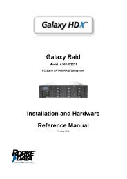
<strong>Galaxy</strong> <strong>16i</strong><br />
2Gb/s Fibre-to-SATA RAID Subsystem<br />
SCSI-to-SATA RAID Subsystem<br />
User <strong>Manual</strong><br />
Revision 1.1<br />
596700
�<br />
Copyright © 2003<br />
ii<br />
This Edition First Published 2003<br />
All rights reserved. This publication may not be reproduced,<br />
transmitted, transcribed, stored in a retrieval system, or<br />
translated into any language or computer language, in any<br />
form or by any means, electronic, mechanical, magnetic,<br />
optical, chemical, manual or otherwise, without the prior<br />
written consent of <strong>Rorke</strong> <strong>Data</strong>, Inc.<br />
Disclaimer<br />
<strong>Rorke</strong> <strong>Data</strong> makes no representations or warranties with respect<br />
to the contents hereof and specifically disclaims any<br />
implied warranties of merchantability or fitness for any<br />
particular purpose. Furthermore, <strong>Rorke</strong> <strong>Data</strong> reserves the<br />
right to revise this publication and to make changes from time<br />
to time in the content hereof without obligation to notify any<br />
person of such revisions or changes. Product specifications<br />
are also subject to change without prior notice.<br />
�
Trademarks<br />
<strong>Rorke</strong> <strong>Data</strong> and the <strong>Rorke</strong> <strong>Data</strong> logo are registered trademarks<br />
of <strong>Rorke</strong> <strong>Data</strong>, Inc.. <strong>Galaxy</strong> <strong>16i</strong> and other names prefixed<br />
with “<strong>Galaxy</strong>” are trademarks of <strong>Rorke</strong> <strong>Data</strong>, Inc.<br />
PowerPC ® is a trademark of International Business Machines<br />
Corporation and Motorola Inc.<br />
Solaris and Java are trademarks of Sun Microsystems, Inc.<br />
All other names, brands, products or services are trademarks<br />
or registered trademarks of its respective owners.<br />
Printed in Taiwan<br />
iii
iv<br />
Warnings and Certifications<br />
FCC (applies in the U.S. and Canada)<br />
This device complies with Part 15 of FCC Rules. Operation<br />
of this device is subject to the following two conditions: 1)<br />
this device may not cause harmful interference, and 2) this<br />
device must accept any interference received, including<br />
interference that may cause undesired operation.<br />
Warning:<br />
Use only shielded cables to connect I/O devices to this<br />
equipment.<br />
You are cautioned that changes or modifications not expressly<br />
approved by the party responsible for compliance could void<br />
your authority to operate the equipment.<br />
This device is in conformity with the EMC
Table of Contents<br />
CHAPTER 1: INTRODUCTION............................................................. 1-1<br />
1.1 MODEL VARIATIONS .................................................................... 1-1<br />
1.1.1 Single-Controller Models ........................................................... 1-2<br />
1.1.2 Dual Redundant Model............................................................... 1-2<br />
1.2 ENCLOSURE CHASSIS.................................................................... 1-3<br />
1.2.1 Front Section .............................................................................. 1-3<br />
1.2.2 Rear Section................................................................................ 1-3<br />
1.2.3 Midplane and Driveplane Boards............................................... 1-3<br />
1.3 GALAXY 16I SUBSYSTEM COMPONENTS ...................................... 1-3<br />
1.3.1 Front Panel Overview................................................................. 1-4<br />
1.3.2 Rear Panel Overview.................................................................. 1-4<br />
1.4 FRONT PANEL COMPONENTS........................................................ 1-6<br />
1.4.1 LCD Panel .................................................................................. 1-6<br />
1.4.2 Drive Trays and Enclosure Bay ID Allocation ........................... 1-7<br />
1.4.3 Dongle Kits ................................................................................. 1-7<br />
1.5 REAR PANEL COMPONENTS.......................................................... 1-8<br />
1.5.1 RAID Controller Modules........................................................... 1-8<br />
1.5.2 Controller Module Interfaces ..................................................... 1-8<br />
1.5.3 Power Supplies Units................................................................ 1-10<br />
1.5.4 Cooling fan modules................................................................. 1-11<br />
1.6 GALAXY 16I SUBSYSTEM MONITORING ..................................... 1-12<br />
1.6.1 I2C bus...................................................................................... 1-12<br />
1.6.2 LED Indicators ......................................................................... 1-13<br />
1.6.3 Firmware (FW) and RAIDWatch GUI...................................... 1-13<br />
1.6.4 Audible Alarms ......................................................................... 1-13<br />
CHAPTER 2: HARDWARE INSTALLATION..................................... 2-1<br />
2.1 INSTALLATION PRE-REQUISITES ................................................... 2-1<br />
2.2 STATIC-FREE INSTALLATION........................................................ 2-2<br />
2.3 UNPACKING THE SUBSYSTEM....................................................... 2-3<br />
2.4 GENERAL INSTALLATION PROCEDURE ......................................... 2-4<br />
2.5 MEMORY MODULE INSTALLATION............................................... 2-4<br />
2.5.1 Selecting the DIMMs .................................................................. 2-5<br />
2.5.2 DIMM Module Installation Steps................................................ 2-6<br />
2.6 BBU INSTALLATION..................................................................... 2-6<br />
2.6.1 Installation Procedure................................................................ 2-7<br />
2.7 INSTALLING THE RAID CONTROLLER MODULE......................... 2-10<br />
2.8 HARD DRIVE INSTALLATION ...................................................... 2-11<br />
2.8.1 Hard Drive Installation Pre-requisites..................................... 2-11<br />
2.8.2 Dongle Kit Installation ............................................................. 2-12<br />
v
2.8.3 Drive Intstallation Without a Dongle/MUX Kit ........................ 2-13<br />
2.8.4 Drive Installation with Dongle/MUX Kit.................................. 2-14<br />
2.9 DRIVE TRAY INSTALLATION ....................................................... 2-16<br />
CHAPTER 3: SYSTEM MONITORING................................................ 3-1<br />
vi<br />
3.1 OVERVIEW.................................................................................... 3-1<br />
3.2 SYSTEM MONITORING .................................................................. 3-1<br />
3.3 FIRMWARE.................................................................................... 3-2<br />
3.4 SYSTEM LEDS .............................................................................. 3-2<br />
3.4.1 Controller Module on Single Controller..................................... 3-2<br />
3.4.2 LCD Panel .................................................................................. 3-6<br />
3.4.3 Drive Tray – Single Controller Model ........................................ 3-7<br />
3.4.4 Drive Tray – Redundant Controller Model................................. 3-7<br />
3.4.5 PSU LEDs ................................................................................... 3-8<br />
3.4.6 Cooling module LEDs................................................................. 3-9<br />
3.5 RAIDWATCH MANAGER.............................................................. 3-9<br />
3.6 NOTIFICATION PROCESSING CENTER (NPC)............................... 3-10<br />
3.7 AUDIBLE ALARM........................................................................ 3-10<br />
3.7.1 Default Threshold Values.......................................................... 3-11<br />
3.7.2 Failed Devices .......................................................................... 3-11<br />
3.8 I 2 C MONITORING........................................................................ 3-12<br />
CHAPTER 4: SYSTEM CONNECTION AND OPERATION ............. 4-1<br />
4.1 OVERVIEW.................................................................................... 4-1<br />
4.2 FC HOST CONNECTION PRE-REQUISITES...................................... 4-1<br />
4.2.1 Cabling........................................................................................ 4-1<br />
4.2.2 FC Lasers.................................................................................... 4-2<br />
4.2.3 SFP Transceivers ........................................................................ 4-2<br />
4.2.4 Fibre Channel Topologies .......................................................... 4-3<br />
4.3 CONNECTING TO HOST PORTS ...................................................... 4-4<br />
4.3.1 Points of Failure ......................................................................... 4-4<br />
4.4 SINGLE CONTROLLER HOST CONNECTION.................................... 4-4<br />
4.4.1 Single Host.................................................................................. 4-4<br />
4.4.2 Dual Hosts .................................................................................. 4-5<br />
4.4.3 Fibre Channel Dual Hosts and Fibre Switch.............................. 4-6<br />
4.5 DUAL-REDUNDANT HOST CONNECTION....................................... 4-7<br />
4.5.1 Dual Hosts .................................................................................. 4-7<br />
4.5.2 Dual Fibre Switches and Dual Hosts.......................................... 4-8<br />
4.6 EXPANSION PORT CONNECTION.................................................... 4-8<br />
4.7 SAMPLE CONFIGURATION: MULTI-PATHING ................................ 4-9<br />
4.7.1 Logical Drive Presentation after Controller Failure................ 4-12<br />
4.7.2 Notes on This Configuration ..................................................... 4-13<br />
4.8 POWER ON.................................................................................. 4-13<br />
4.8.1 Check List.................................................................................. 4-13<br />
4.8.2 Power On Procedure ................................................................ 4-14
4.8.3 <strong>Galaxy</strong> <strong>16i</strong> Power On-Procedure ............................................. 4-15<br />
4.8.4 Power On Status Check ............................................................ 4-16<br />
4.8.5 LCD Screen............................................................................... 4-17<br />
4.9 POWER OFF PROCEDURE ............................................................ 4-18<br />
CHAPTER 5: SYSTEM MAINTENANCE............................................. 5-1<br />
5.1 OVERVIEW.................................................................................... 5-1<br />
5.2 REPLACING CONTROLLER MODULE COMPONENTS ...................... 5-2<br />
5.2.1 Re-Moving the controller Module............................................... 5-2<br />
5.2.2 Re-placing the BBU .................................................................... 5-3<br />
5.2.3 Replacing a Failed DIMM Module............................................. 5-3<br />
5.2.4 Replacing the controller Module ................................................ 5-4<br />
5.3 REPLACING A FAILED PSU MODULE............................................ 5-5<br />
5.4 REPLACING A FAILED COOLING FAN MODULE............................ 5-7<br />
5.5 REPLACING A FAILED HARD DRIVE.............................................. 5-9<br />
5.6 REPLACING A DONGLE/MUX KIT ................................................ 5-9<br />
APPENDIX A: SYSTEM FEATURES................................................... A-1<br />
A.1 OVERVIEW........................................................................................ A-1<br />
A.2 FLEXIBLE CONFIGURATION OPTIONS................................................ A-1<br />
A.2.1 Single and Redundant Models....................................................A-1<br />
A.2.2 Rear Panel Variations................................................................A-1<br />
A.2.3 Fibre Channel Configuration.....................................................A-2<br />
A.3 RAID SUPPORT AND RAID LEVELS................................................. A-2<br />
A.3.1 JBOD..........................................................................................A-2<br />
A.3.2 RAID 0........................................................................................A-3<br />
A.3.3 RAID 1........................................................................................A-4<br />
A.3.4 RAID 1(0+1) ..............................................................................A-5<br />
A.3.5 RAID 3........................................................................................A-6<br />
A.3.6 RAID 5........................................................................................A-7<br />
A.3.7 RAID 30 and RAID 50................................................................A-8<br />
A.3.8 Non-RAID Storage .....................................................................A-8<br />
A.3.9 Spares.........................................................................................A-9<br />
A.4 REDUNDANT FEATURES.................................................................. A-10<br />
A.4.1 Dual-Active Redundant Controllers.........................................A-10<br />
A.4.2 Redundant <strong>Data</strong> Paths .............................................................A-10<br />
A.5 FAULT TOLERANCE ........................................................................ A-10<br />
A.5.1 Intelligent Drive Handling .......................................................A-10<br />
A.5.2 Hot-swappable active components...........................................A-11<br />
A.5.3 Global and Local Spares..........................................................A-11<br />
A.5.4 Hot-Swapping of Drives ...........................................................A-11<br />
A.5.5 S.M.A.R.T. Support...................................................................A-12<br />
A.5.6 Other Fault Tolerant Features.................................................A-12<br />
A.6 SAN FEATURES.............................................................................. A-12<br />
A.6.1 Logical Unit Numbers ..............................................................A-12<br />
vii
A.6.2 LUN Masking............................................................................A-12<br />
A.7 MECHANICAL FEATURES ................................................................ A-13<br />
A.7.1 Modular Design........................................................................A-13<br />
A.7.2 Cableless Design ......................................................................A-13<br />
APPENDIX B: ACCESSING THE RAIDWATCH SOFTWARE....... B-1<br />
B.1 SOFTWARE INSTALLATION REQUIREMENTS................................. B-1<br />
B.1.1 What Is the “Disk Reserved Space?” .........................................B-1<br />
B.1.2 Web-Based Management ............................................................B-2<br />
B.1.3 Requirements ..............................................................................B-2<br />
B.2 CONNECTING ETHERNET PORT: ................................................... B-3<br />
B.3 CONFIGURING THE CONTROLLER................................................. B-3<br />
B.4 NPC ONBOARD ........................................................................... B-7<br />
APPENDIX C: SPECIFICATIONS........................................................ C-1<br />
viii<br />
C.1 TECHNICAL SPECIFICATIONS ....................................................... C-1<br />
C.2 CONTROLLER SPECIFICATIONS .................................................... C-3<br />
C.2.1 Configuration ............................................................................ C-3<br />
C.2.2 Architecture............................................................................... C-4<br />
C.2.3 Environmental Specifications.................................................... C-4<br />
C.3 DRIVE TRAY SPECIFICATIONS...................................................... C-5<br />
C.4 POWER SUPPLY SPECIFICATIONS ................................................. C-5<br />
C.5 RAID MANAGEMENT .................................................................. C-6<br />
C.6 FAULT TOLERANCE MANAGEMENT ............................................. C-6
Safety Precautions<br />
Precautions and instructions<br />
� Prior to powering on the subsystem, ensure that the<br />
correct power range is being used.<br />
� The <strong>Galaxy</strong> <strong>16i</strong> subsystem comes with 16 drive bays<br />
(slots). Leaving any of these slots empty will greatly<br />
affect the efficiency of the airflow within the enclosure,<br />
and will consequently lead to the system overheating,<br />
which can cause irreparable damage.<br />
� If a module fails, leave it in place until you have a<br />
replacement unit and you are ready to replace it.<br />
� Airflow Consideration: The subsystem requires an<br />
airflow clearance especially at the front and at the rear.<br />
� To handle subsystem modules, use the retention screws,<br />
eject levers, and the metal frames/face plates. Avoid<br />
touching PCB boards or connector pins.<br />
� To comply with safety, emission, or thermal<br />
requirements, none of the covers or replaceable modules<br />
should be removed. Make sure that during operation, all<br />
enclosure modules and covers are securely in place.<br />
� Be sure that the rack cabinet into which the subsystem<br />
chassis is to be installed provides sufficient ventilation<br />
channels and airflow circulation around the subsystem.<br />
� Provide a soft, clean surface to place your subsystem on<br />
before working on it. Servicing on a rough surface may<br />
damage the exterior of the chassis.<br />
� If it is necessary to transport the subsystem, repackage all<br />
drives and replaceable modules separately.<br />
ix
x<br />
� Dual redundant controller models come with two<br />
controller modules that must be installed into the<br />
subsystem. Single controller modules come with a single<br />
controller module and a metal sheet is placed over the<br />
lower controller bay at the rear of the subsystem. Since<br />
single controller modules cannot be upgraded this metal<br />
sheet should NEVER be removed.<br />
ESD Precautions:<br />
Observe all conventional anti-ESD methods while handling<br />
system modules. The use of grounded wrist-strap and an antistatic<br />
work pad are recommended. Avoid dust or debris in<br />
your work area.<br />
About This <strong>Manual</strong>:<br />
This manual<br />
� introduces the the <strong>Galaxy</strong> <strong>16i</strong> RAID Subsystem series.<br />
� describes all the active components in the system.<br />
� provides recommendations and details about the hardware<br />
installation process of the subsystem.<br />
� briefly describes how to monitor the subsystem.<br />
� describes how to maintain the subsystem.<br />
This manual does not<br />
� describe components that are not user-serviceable.<br />
� describe the configuration options of firmware, using<br />
terminal emulation programs or the RAIDWatch GUI that<br />
came with your subsystem.<br />
� give a detailed description of the RAID processing units,<br />
the RAID controllers embedded within the subsystem.
Who should read this manual?<br />
This manual assumes that its readers are experienced with<br />
computer hardware installation and are familiar with storage<br />
enclosures.<br />
Related Documentation<br />
� Generic Operation <strong>Manual</strong><br />
� RAIDWatch User’s <strong>Manual</strong><br />
Conventions<br />
Naming<br />
From this point on and throughout the rest of this manual the<br />
<strong>Galaxy</strong> <strong>16i</strong> series is referred to as simply the “subsystem” or<br />
the “system”.<br />
Warnings<br />
Warnings appear where overlooked details may cause damage<br />
to the equipment or result in personal injury. Warnings should<br />
be taken seriously. Warnings are easy to recognize. The word<br />
“warning” is written as “WARNING”, both capitalized and<br />
bold and is followed by text in italics. The italicized text is the<br />
warning message.<br />
Cautions<br />
Cautionary messages should also be heeded for the messages<br />
can help you reduce the chance of losing data or damaging the<br />
system. Cautions are easy to recognize. The word “caution” is<br />
written as “CAUTION”, both capitalized and bold and is<br />
followed by text in italics. The italicized text is the cautionary<br />
message.<br />
xi
xii<br />
Notes<br />
These are messages that are used to inform the reader of<br />
essential but non-critical information. These messages should<br />
be read carefully and any directions or instructions contained<br />
herein can help you avoid making mistakes. Notes are easy to<br />
recognize. The word “note” is written as “NOTE”, it is both<br />
capitalized and bold and is followed by text in italics. The<br />
italicized text is the cautionary message.<br />
Lists<br />
Bulleted Lists: - Bulleted lists are statements of non-sequential<br />
facts. They can be read in any order. Each statement is<br />
preceded by a round black dot “∙”.<br />
Numbered Lists: - Numbered lists are used to describe<br />
sequential steps a user should follow in order.<br />
Software and Firmware Updates<br />
Please contact your system vendor or visit <strong>Rorke</strong> <strong>Data</strong>’s FTP<br />
site (ftp.rorke.com) for the latest software or firmware<br />
updates. NOTE that the firmware version installed on your<br />
system should provide the complete functionality listed in the<br />
specification sheet/user’s manual. We provide special<br />
revisions for various application purposes. Therefore, DO<br />
NOT upgrade your firmware unless you fully understand what<br />
a firmware revision will do.<br />
Problems that occur during the updating process may cause<br />
unrecoverable errors and system down time. Always consult<br />
technical personnel before proceeding with any firmware<br />
upgrade.
Chapter 1<br />
Introduction<br />
The serial ATA (SATA) <strong>Galaxy</strong> <strong>16i</strong> RAID subsystem series<br />
described in this manual comes in three different models that<br />
provide users with flexible configuration options. The differences<br />
between the three models are described below.<br />
1.1 Model Variations<br />
Two single controller models and one redundant controller model<br />
make up the three available models in the <strong>Galaxy</strong> <strong>16i</strong> SATA<br />
RAID storage subsystem series.<br />
The three models are shown in Table 1- 1.<br />
Model Name Host<br />
Channels<br />
<strong>Galaxy</strong> <strong>16i</strong><br />
GAL16IR-U3DS<br />
<strong>Galaxy</strong> <strong>16i</strong><br />
GAL16IR-FC2S<br />
<strong>Galaxy</strong> <strong>16i</strong><br />
GAL16IR-FC2D<br />
2 x Ultra 160<br />
SCSI<br />
2 x 2Gbit/sec<br />
Fibre Channel<br />
4 x 2Gbit/sec<br />
Fibre Channel<br />
Controller Board<br />
GALI-IFT-7260S-16U3D<br />
(Single Controller, Dual-Host<br />
Capable)<br />
GALI-IFT-7260S-16F2D<br />
(Single Controller, Dual-Host<br />
Capable)<br />
GALI-IFT-7260R-16F2D<br />
(Dual Redundant Controllers,<br />
Quad-Host Capable)<br />
Table 1- 1: Available <strong>Galaxy</strong> <strong>16i</strong> RAID Subsystem Models<br />
<strong>Galaxy</strong> <strong>16i</strong> User’s <strong>Manual</strong> 1-1
1-2<br />
NOTE:<br />
Please check to see that you have the correct model. If you have a<br />
different model to the one you have ordered, please contact your<br />
sales representative immediately.<br />
1.1.1 Single-Controller Models<br />
The single controller <strong>Galaxy</strong> <strong>16i</strong> subsystems, the <strong>Galaxy</strong> <strong>16i</strong><br />
GAL16IR-U3DS and the <strong>Galaxy</strong> <strong>16i</strong> GAL16IR-FC2S, combine<br />
either 2Gbps Fibre Channel (FC) or SCSI-160 host channels with<br />
16 SATA drives in a single storage subsystem. These models are<br />
ideal for applications that require greater performance than data<br />
availability, and when full redundancy is not a critical<br />
requirement.<br />
1.1.2 Dual Redundant Model<br />
The dual redundant controller <strong>Galaxy</strong> <strong>16i</strong> subsystem (<strong>Galaxy</strong> <strong>16i</strong><br />
GAL16IR-FC2D) combines two, dual redundant, 2Gbps FC<br />
controllers with 16 SATA drives in the <strong>Galaxy</strong> <strong>16i</strong> subsystem.<br />
When equipped with dual-redundant controllers, the subsystem is<br />
capable of full redundancy and is able to sustain single failure of<br />
any of its active components. RAID controller failure is<br />
transparent to host computers and the failover process is<br />
automatically managed by firmware.<br />
The redundant model operates in a Dual-Active RAID controller<br />
configuration. The two controllers work together to enhance the<br />
overall performance of the subsystem. Cache coherency is<br />
supported and the data cached in memory is protected by a battery<br />
module (BBU) that is able to sustain cache memory for up to 72<br />
hours. An exact replica of the unfinished writes by hosts is<br />
constantly cached in both controllers. This ensures that there is no<br />
single point of failure when one controller fails. Users can freely<br />
associate logical arrays with multiple target IDs.<br />
<strong>Galaxy</strong> <strong>16i</strong> User’s <strong>Manual</strong>
1.2 Enclosure Chassis<br />
The <strong>Galaxy</strong> <strong>16i</strong> subsystem enclosure is divided into a front and<br />
rear section.<br />
NOTE:<br />
Components accessed through the front panel are referred to as<br />
“Front Panel Components” and Components accessed through<br />
the rear panel are referred to as “Rear Panel Components.”<br />
1.2.1 Front Section<br />
The front section of the <strong>Galaxy</strong> <strong>16i</strong> subsystem features a 4 x 4<br />
layout for sixteen 3.5” drives and houses a foldable LCD panel.<br />
1.2.2 Rear Section<br />
The rear section of the <strong>Galaxy</strong> <strong>16i</strong> subsystem is accessed through<br />
the rear panel and is reserved for the RAID controller module(s),<br />
power supply units (PSU), cooling fan modules and power<br />
switches.<br />
1.2.3 Midplane and Driveplane Boards<br />
Integrated driveplane and midplane boards separate the front and<br />
rear sections of the <strong>Galaxy</strong> <strong>16i</strong> subsystem. These PCB boards<br />
provide logic level signals and low voltage power paths. They<br />
contain no user-serviceable components.<br />
1.3 <strong>Galaxy</strong> <strong>16i</strong> Subsystem Components<br />
All the active components on the <strong>Galaxy</strong> <strong>16i</strong> subsystems can be<br />
accessed through either the front or rear panel. The modular<br />
design of the active components facilitates their easy installation<br />
and removal. Hot-swap mechanisms are incorporated to eliminate<br />
power surges and signal glitches that might happen while<br />
removing or installing these modules.<br />
<strong>Galaxy</strong> <strong>16i</strong> User’s <strong>Manual</strong> 1-3
1-4<br />
1.3.1 Front Panel Overview<br />
The front panel of the <strong>Galaxy</strong> <strong>16i</strong> RAID subsystem described in<br />
this manual is shown in Figure 1- 1. A description of each front<br />
panel component is given below.<br />
LCD Panel<br />
Handle Drive Trays<br />
Handle<br />
Figure 1- 1: Front View – RAID Appliance Models<br />
The front panel shown in Figure 1- 1 is designed to accommodate<br />
the following components:<br />
� LCD Panel:- The LCD Panel shows system information<br />
and can be used to configure and monitor the <strong>Galaxy</strong> <strong>16i</strong><br />
subsystem.<br />
� Drive bays with drive tray canisters:- The drive bays are<br />
used to house the <strong>Galaxy</strong> <strong>16i</strong> subsystem hard drives.<br />
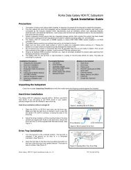
1.3.2 Rear Panel Overview<br />
The rear panel of the RAID subsystem described in this manual is<br />
shown in Figure 1- 2. A description of each rear panel component<br />
is given below.<br />
<strong>Galaxy</strong> <strong>16i</strong> User’s <strong>Manual</strong>
Cooling FAN Module Cooling FAN Module<br />
Power Switch<br />
Controller Module Power Switch<br />
PSU Controller Module PSU<br />
Figure 1- 2: Rear View – Redundant Controller FC <strong>Galaxy</strong> <strong>16i</strong> Subsystem<br />
The rear panel shown in Figure 1- 2 is designed to accommodate<br />
the following components:<br />
� RAID controller module(s):- The controller modules contain<br />
both the RAID controllers and the battery back up units<br />
(BBU), which are optional for the single controller models.<br />
NOTE:<br />
For the single RAID Controller model, a metal sheet will be<br />
placed over the lower controller bay at the rear of the<br />
subsystem. The single controller module that came with the<br />
subsystem must be installed in the upper controller bay.<br />
� PSU:- The PSUs are used to provide power to the subsystem.<br />
� Cooling fan modules:- The redundant cooling FAN modules<br />
are used to ventilate the subsystem and to reduce the<br />
temperature within the subsystem.<br />
� Power Switches:- The power switches are used to turn the<br />
system on and off.<br />
<strong>Galaxy</strong> <strong>16i</strong> User’s <strong>Manual</strong> 1-5
1.4 Front Panel Components<br />
1-6<br />
1.4.1 LCD Panel<br />
Figure 1- 3: LCD Panel<br />
The LCD panel shown in Figure 1- 3 consists of a 16x2 character<br />
LCD screen with push buttons and LED status indicators. The<br />
LCD front panel provides full access to all RAID configurations<br />
and monitoring. After powering up the subsystem, the initial<br />
screen will show the subsystem model name. A different name<br />
may be assigned for the system or different arrays. This will<br />
enable easier identification in a topology with numerous arrays.<br />
In the redundant controller subsystem, two controller modules are<br />
present. After powering up the primary controller information<br />
will be shown. To view secondary controller information, press<br />
both the “Up” and “Down” arrow keys simultaneously. When<br />
both controllers are functioning properly, all the configuration<br />
changes can be made through the primary controller. If the<br />
primary controller malfunctions, system configuration changes<br />
must be made through the secondary controller.<br />
<strong>Galaxy</strong> <strong>16i</strong> User’s <strong>Manual</strong>
1.4.2 Drive Trays and Enclosure Bay ID<br />
Allocation<br />
16 Drive bays for the installation of standard 1” pitch, 3.5” disk<br />
drives. The drive bays are located on the front panel and are<br />
easily accessible to the end user.<br />
As shown in Figure 1- 4 below, the <strong>Galaxy</strong> <strong>16i</strong> subsystem is<br />
housed in an enclosure that is 4 bays wide by 4 bays high. Drive<br />
bays (slots) are, when viewed from the front, numbered 1 to 16<br />
from left to right, then from top to bottom.<br />
1 2 3 4<br />
5 6 7 8<br />
9 10 11 12<br />
13 14 15 16<br />
Figure 1- 4: Hard Drive IDs<br />
The default ID for slot 0 is located at the top left hand corner and<br />
is set to “1.” This setting should not cause any problems if the<br />
hard drives installed in this subsystem do not share the same loop<br />
with other devices. The last slot ID, located at the bottom right<br />
hand corner, will be “16”.<br />
NOTE:<br />
Users cannot change the default ID settings for the drives. The ID<br />
settings for the drive are pre-assigned.<br />
1.4.3 Dongle Kits<br />
Single Controller Subsystems:- Both single controller <strong>Galaxy</strong> <strong>16i</strong><br />
subsystems can accommodate SATA drives. If users wish to use<br />
parallel ATA (PATA) hard drives in their subsystem, then SATAto-PATA<br />
dongle kits must be purchased separately and installed<br />
independently by the end user.<br />
<strong>Galaxy</strong> <strong>16i</strong> User’s <strong>Manual</strong> 1-7
1-8<br />
Redundant Controller Subsystems:- Prior to purchasing a<br />
redundant controller subsystem, the user must determine whether<br />
they would prefer to use SATA or PATA hard drives. If they wish<br />
to use SATA hard drives, the subsystem will be shipped with<br />
SATA-to-SATA MUX kits that must be installed by the end user.<br />
If a user wishes to use PATA hard drives, the subsystem will be<br />
shipped with 16 SATA-to-PATA MUX kits that must also be<br />
independently installed.<br />
1.5 Rear Panel Components<br />
1.5.1 RAID Controller Modules<br />
The RAID controller module contains a main circuit board, a<br />
dedicated driveplane management interface, and a BBU that is<br />
optional for the single controller models but standard for the<br />
redundant controller models. The controller module contains no<br />
user-serviceable components. Except when replacing a faulty<br />
unit, installing a BBU, or installing/upgrading the cache memory<br />
inside, the controller module should never be removed or opened.<br />
WARNING:<br />
Although the RAID Controller can be removed, the only time a<br />
user should touch the controller itself is to install the memory<br />
modules or the BBU. Unnecessary tampering with the RAID<br />
controller can damage the controller and make the system<br />
unusable.<br />
1.5.2 Controller Module Interfaces<br />
The <strong>Galaxy</strong> <strong>16i</strong> subsystem controllers come with the following<br />
interfaces.<br />
<strong>Galaxy</strong> <strong>16i</strong> User’s <strong>Manual</strong>
Host Interfaces<br />
Subsystem Model Host Channels<br />
<strong>Galaxy</strong> <strong>16i</strong> GAL16IR-<br />
U3DS<br />
<strong>Galaxy</strong> <strong>16i</strong> GAL16IR-<br />
FC2S<br />
<strong>Galaxy</strong> <strong>16i</strong> GAL16IR-<br />
FC2D<br />
Table 1- 2: System Host Channels<br />
2 x Ultra 160 SCSI<br />
2 x 2Gbit/sec Fibre Channel<br />
4 x 2Gbit/sec Fibre Channel<br />
SCSI-160 Host Ports:- The SCSI host connects to the <strong>Galaxy</strong> <strong>16i</strong><br />
subsystem through two mini-SCSI connectors, which are located<br />
at the back of the controller modules.<br />
FC Host Ports:- The FC host connects to the <strong>Galaxy</strong> <strong>16i</strong><br />
subsystem through two small form factor pluggable (SFP)<br />
connector, which are located at the back of the controller<br />
modules.<br />
FC Speed Detection:- Speed auto-detection is specified by the FC<br />
standard. If a 1Gbps port is connected to a 2Gbps port, it will<br />
negotiate down and run at 1Gbps. If there are two 2Gbps ports on<br />
either end of the link, the link will be run at 2Gbps.<br />
Drive Interfaces<br />
All the models come with sixteen SATA drive channels that are<br />
connected to the back plane.<br />
RCC Channels<br />
The controllers in the redundant controller <strong>Galaxy</strong> <strong>16i</strong> subsystem,<br />
the <strong>Galaxy</strong> <strong>16i</strong> GAL16IR-FC2D, each come with a single<br />
<strong>Galaxy</strong> <strong>16i</strong> User’s <strong>Manual</strong> 1-9
1-10<br />
dedicated onboard 2Gbps redundant cache coherence (RCC)<br />
channel that communicates between the two controllers.<br />
Expansion Ports<br />
Redundant controller subsystems come with two extra 2Gbps<br />
channels (one on each controller) that can be used for expansion.<br />
These ports can be used to connect to other JBODs, increasing the<br />
overall storage capacity of the SAN. (Single controller models do<br />
not have the added expansion port.)<br />
Ethernet Ports<br />
All the controller modules on the <strong>Galaxy</strong> <strong>16i</strong> subsystems come<br />
with a single RJ-45 Ethernet port. The Ethernet port is used for<br />
remote management through the network. When operated in the<br />
dual active mode, system configuration is handled through one of<br />
the controllers. In the event one controller fails, the Ethernet port<br />
on the other controller inherits the configured IP and continues the<br />
monitoring or configuration service.<br />
RS-232C (Audio Jacks)<br />
The controller modules all come with two RS-232C (Audio Jack)<br />
serial ports. One serial port is used for remote management and<br />
the other for UPS support.<br />
1.5.3 Power Supply Units<br />
Two 460W redundant hot swappable power supply units (PSUs)<br />
are located at the rear of the enclosure. If one PSU fails, the<br />
second PSU will be able to supply sufficient power for the system<br />
to keep running. The power switches for these PSUs are located at<br />
the top of the Rear Panel of the subsystem (see Figure 1- 2).<br />
The specifications for the PSUs are shown in Table 1- 3 below.<br />
<strong>Galaxy</strong> <strong>16i</strong> User’s <strong>Manual</strong>
Specification<br />
Nominal power 460 Watts with active PFC<br />
Input voltage 90 to 260VAC +-10%<br />
Input frequency 47 ~ 63 Hz<br />
Input current 8A @90VAC; 4A @230VAC<br />
Power factor<br />
correction<br />
Yes<br />
Hold-up time At least 16ms at 115/230VAC full load after<br />
a loss of AC input<br />
Over temperature<br />
protection<br />
Lost cooling or excessive ambient<br />
temperature<br />
Size 265(D) x 107(W) x 42.2(H) mm.<br />
Cooling 11 CFM<br />
Acoustic noise 115V input, full load of +5V;<br />
0.5A of +12V<br />
Table 1- 3: PSU Specifications<br />
1.5.4 Cooling fan modules<br />
50 dB<br />
max.<br />
Two pre-installed cooling fan modules (see Figure 1- 5) come<br />
with the subsystem. Two 9.7cm blowers housed in each cooling<br />
module and can provide a total of 61 CFM of airflow running at<br />
the speed of 3600rpm.<br />
<strong>Galaxy</strong> <strong>16i</strong> User’s <strong>Manual</strong> 1-11
1-12<br />
Figure 1- 5: Bottom view of a cooling fan module<br />
1.6 <strong>Galaxy</strong> <strong>16i</strong> Subsystem Monitoring<br />
The <strong>Galaxy</strong> <strong>16i</strong> RAID Subsystem comes with a number of<br />
different monitoring methods that enable users to constantly be<br />
updated on the status of the system and individual components.<br />
The following monitoring features are included in the subsystem.<br />
1.6.1 I 2 C bus<br />
The following <strong>Galaxy</strong> <strong>16i</strong> subsystem elements are interfaced to<br />
the RAID controller over a non-user serviceable I 2 C bus:<br />
� PSU<br />
� Cooling FAN Module<br />
1.6.2 LED Indicators<br />
The following active components all come with LEDs that<br />
indicate the status of the individual component.<br />
� RAID Controller<br />
� LCD Panel<br />
� Cooling FAN Module<br />
� PSU Module<br />
� Drive Trays<br />
<strong>Galaxy</strong> <strong>16i</strong> User’s <strong>Manual</strong>
1.6.3 Firmware (FW) and RAIDWatch GUI<br />
Firmware:- The firmware is pre-installed software that is used to<br />
configure the subsystem. The FW can be accessed through either<br />
the front panel LCD module or a terminal emulation program that<br />
is installed on an external computer that is connected to the host.<br />
RAIDWatch:- RAIDWatch is a premier web-based graphics user<br />
interface (GUI) that can be installed on a remote computer and<br />
accessed via the web.<br />
1.6.4 Audible Alarms<br />
The <strong>Galaxy</strong> <strong>16i</strong> subsystem comes with audible alarms that will be<br />
triggered when certain active components fail or when certain<br />
(controller or subsystem) thresholds are exceeded. If you hear an<br />
audible alarm being emitted from the <strong>Galaxy</strong> <strong>16i</strong> subsystem it is<br />
imperative that you determine and rectify the problem<br />
immediately.<br />
WARNING:<br />
Failing to respond when an audible alarm is heard can lead to<br />
permanent damage of the <strong>Galaxy</strong> <strong>16i</strong> subsystem. If an audible<br />
alarm is heard, rectify the problem as soon as possible.<br />
<strong>Galaxy</strong> <strong>16i</strong> User’s <strong>Manual</strong> 1-13
1-14<br />
This page is intentionally left blank<br />
<strong>Galaxy</strong> <strong>16i</strong> User’s <strong>Manual</strong>
audible alarm, 1-13<br />
BBU, 1-2, 1-5, 1-8<br />
cache coherency, 1-2<br />
controller module, 1-3, 1-8<br />
cooling fan module, 1,-3, 1-5, 1-<br />
11<br />
drive bay, 1-4, 1-7<br />
drive ID, 1-7<br />
driveplane, 1-3, 1-8<br />
dual active, 1,-2, 1-10<br />
dual redundant, 1-2<br />
ethernet port, 1-10<br />
expansion port, 1-10<br />
failover, 1-2<br />
firmware, 1-13<br />
front panel, 1-3, 1-4<br />
GUI, 1-13<br />
hot-swap mechanism, 1-3<br />
I 2 C bus, 1-12<br />
LCD panel, 1-6<br />
LCD Panel, 1-4<br />
LED, 1-12<br />
midplane, 1-3<br />
mini-SCSI connector, 1-9<br />
MUX kit, 1-8<br />
power switch, 1-3, 1-5, 1-10<br />
primary controller, 1-6<br />
PSU, 1-3, 1-5, 1-10<br />
RAIDWatch, 1-13<br />
RCC channel, 1-9<br />
rear panel, 1-3, 1-4, 1-5, 1-10<br />
redundant controller, 1-6<br />
remote management, 1-10<br />
RJ-45 port, 1-10<br />
RS-232C (Audio Jack) serial<br />
port, 1-10<br />
SATA, 1-7<br />
SATA drive channel, 1-9<br />
secondary controller, 1-6<br />
SFP connector, 1-9<br />
single controller, 1-2, 1-7<br />
speed auto-detection, 1-9<br />
terminal emulation program, 1-<br />
13<br />
UPS, 1-10<br />
<strong>Galaxy</strong> <strong>16i</strong> User’s <strong>Manual</strong> 1-15
CHAPTER 1: INTRODUCTION............................................................. 1-1<br />
1.1 MODEL VARIATIONS..................................................................... 1-1<br />
1.1.1 Single-Controller Models............................................................ 1-2<br />
1.1.2 Dual Redundant Model ............................................................... 1-2<br />
1.2 ENCLOSURE CHASSIS .................................................................... 1-3<br />
1.2.1 Front Section............................................................................... 1-3<br />
1.2.2 Rear Section ................................................................................ 1-3<br />
1.2.3 Midplane and Driveplane Boards............................................... 1-3<br />
1.3 GALAXY 16I SUBSYSTEM COMPONENTS....................................... 1-3<br />
1.3.1 Front Panel Overview ................................................................. 1-4<br />
1.3.2 Rear Panel Overview .................................................................. 1-4<br />
1.4 FRONT PANEL COMPONENTS ........................................................ 1-6<br />
1.4.1 LCD Panel................................................................................... 1-6<br />
1.4.2 Drive Trays and Enclosure Bay ID Allocation ........................... 1-7<br />
1.4.3 Dongle Kits.................................................................................. 1-7<br />
1.5 REAR PANEL COMPONENTS .......................................................... 1-8<br />
1.5.1 RAID Controller Modules ........................................................... 1-8<br />
1.5.2 Controller Module Interfaces...................................................... 1-8<br />
1.5.3 Power Supplies Units ................................................................ 1-10<br />
1.5.4 Cooling fan modules.................................................................. 1-11<br />
1.6 GALAXY 16I SUBSYSTEM MONITORING...................................... 1-12<br />
1.6.1 I2C bus ...................................................................................... 1-12<br />
1.6.2 LED Indicators.......................................................................... 1-13<br />
1.6.3 Firmware (FW) and RAIDWatch GUI...................................... 1-13<br />
1.6.4 Audible Alarms.......................................................................... 1-13<br />
Figure 1- 1: Front View – RAID Appliance Models .......................................4<br />
Figure 1- 2: Rear View – Redundant Controller FC <strong>Galaxy</strong> <strong>16i</strong> Subsystem...5<br />
Figure 1- 3: LCD Panel ....................................................................................6<br />
Figure 1- 4: Hard Drive IDs .............................................................................7<br />
Figure 1- 5: Bottom view of the cooling fan module.....................................12<br />
1-16<br />
<strong>Galaxy</strong> <strong>16i</strong> User’s <strong>Manual</strong>
Chapter 2<br />
Hardware<br />
Installation<br />
The modular design of the <strong>Galaxy</strong> <strong>16i</strong> RAID subsystem simplifies<br />
the installation process. This chapter describes the installation<br />
procedures for the <strong>Galaxy</strong> <strong>16i</strong> RAID Controller subsystem.<br />
CAUTION<br />
Please note that the installation instructions described in this<br />
manual should be carefully followed. If they are not carefully<br />
followed, your system may be damaged.<br />
2.1 Installation Pre-requisites<br />
1. Static Free Installation Environment – The <strong>Galaxy</strong> <strong>16i</strong><br />
subsystem must be installed in a static free environment to<br />
minimize the possibility of electrostatic discharge (ESD)<br />
damage. (See Section 2.2).<br />
2. Component Check – Before the <strong>Galaxy</strong> <strong>16i</strong> subsystem is<br />
installed, users should, during the unpacking process, check to<br />
see that they have received all the required components. (See<br />
Section 2.3 )<br />
3. Memory Modules – If the users wish to change the preinstalled<br />
memory modules, the separately purchased modules<br />
must be installed by the end user. (See Section 2.5.1)<br />
4. Dongle Kits- For the redundant models, either SATA-to-SATA<br />
or SATA-to-PATA MUX kits must be installed for the<br />
redundant controller subsystem. If you wish to use PATA<br />
<strong>Galaxy</strong> <strong>16i</strong> User’s <strong>Manual</strong> 2-1
2-2<br />
drives in the single controller subsystem a SATA-to-PATA<br />
dongle kit needs to be installed. (See Section 2.8.2)<br />
5. Hard drives – SATA or PATA hard drives must be purchased<br />
separately prior to installation of the <strong>Galaxy</strong> <strong>16i</strong> subsystem.<br />
(See Section 2.8.3 and Section 2.8.4)<br />
6. Cabling – All the FC cables that are used to connect the<br />
<strong>Galaxy</strong> <strong>16i</strong> subsystem to the host and used for the expansion<br />
port must be purchased separately. (See Section 4.2.1)<br />
7. SFP Transceivers – If the FC cables that were previously<br />
purchased do not come with pre-installed SFP transceivers,<br />
these must be separately purchased and connected to the SFP<br />
cables. (See Section 4.2.3)<br />
2.2 Static-Free Installation<br />
Static electricity can damage the electronic components of the<br />
system. Most of the controllers that are returned for repair are the<br />
results of improper installation and ESD damage. To prevent ESD<br />
damage to any of the components, before touching or handling them<br />
follow these precautions:<br />
� discharge the static electricity from your body by wearing an<br />
anti-static wrist band or by touching a grounded metal surface.<br />
� Avoid carpets, plastic, vinyl or styrofoam in your work area.<br />
� Handle any components by holding its edges or metal frame.<br />
Avoid touching PCB boards or connector pins.<br />
2.3 Unpacking the Subsystem<br />
The <strong>Galaxy</strong> <strong>16i</strong> subsystem will be packed in two separate levels as<br />
shown in Figure 2- 1 below. Carefully check the items contained in<br />
each box before proceeding with installation.<br />
<strong>Galaxy</strong> <strong>16i</strong> User’s <strong>Manual</strong>
NOTE:<br />
A detailed packing list can be found in the Appendix D of this<br />
manual.<br />
Drive Trays x 16<br />
Figure 2- 1: Side View of the Packing Case<br />
Upper Level:- The boxes on the upper level contain:<br />
16 drive canisters<br />
controller modules<br />
� battery modules (Optional item for single controller<br />
subsystems)<br />
accessories<br />
Lower Level:- The lower box should contain the enclosure chassis<br />
with all the pre-installed components. The pre-installed<br />
components should include:<br />
� PSU modules<br />
� LCD panel<br />
� Cooling FAN modules<br />
� Midplane<br />
� Driveplane<br />
Enclosure<br />
Accessories<br />
Controller Modules<br />
Accessory items are placed on top of the controller modules.<br />
They include power cords, Audio Jack cable and a CD<br />
containing both the Hardware <strong>Manual</strong> (this document) and the<br />
RAIDWatch User’s <strong>Manual</strong>.<br />
<strong>Galaxy</strong> <strong>16i</strong> User’s <strong>Manual</strong> 2-3
2.4 General Installation Procedure<br />
2-4<br />
If the following steps are followed, the installation of the <strong>Galaxy</strong><br />
<strong>16i</strong> subsystem should be smooth and efficient. Detailed, illustrated<br />
instructions for each step are given in the following sections.<br />
CAUTION<br />
To ensure that your system is correctly installed, please follow<br />
the steps outlined below. If you follow these steps then the<br />
installation will be fast and efficient. If you do not follow these<br />
steps then you may accidentally install the hardware incorrectly.<br />
1. Install the cache memory (if change needs to be made) –<br />
Section 2.5.2.<br />
2. Install the BBU (if required by user)– Section 2.6<br />
3. Install the Controller Module – Section 2.7<br />
4. Install the hard drives into the drive trays - Section 2.8<br />
5. Install the drive trays (with the hard drives) into the<br />
subsystem - Section 2.9<br />
2.5 Memory Module Installation<br />
The <strong>Galaxy</strong> <strong>16i</strong> subsystem comes with pre-installed SDRAM<br />
DIMMs. The single controller models come with 128MB SDRAM<br />
DIMM modules and the redundant models come with 256MB<br />
SDRAM DIMM modules. If the user wishes to use SDRAM<br />
modules with a different size, the pre-installed modules must be<br />
removed and the new ones installed.<br />
If you do not wish to change the memory modules, please move on<br />
to the Section 2.6. If you wish to install new memory modules<br />
please refer to the installation procedure below.<br />
<strong>Galaxy</strong> <strong>16i</strong> User’s <strong>Manual</strong>
2.5.1 Selecting the DIMMs<br />
If you are changing the memory modules on the <strong>Galaxy</strong> <strong>16i</strong><br />
subsystem controller, when purchasing the DIMM modules the<br />
following factors must be considered:<br />
Type – The <strong>Galaxy</strong> <strong>16i</strong> subsystem is able to support SDRAM<br />
DIMM memory modules with ECC checking.<br />
Size – The <strong>Galaxy</strong> <strong>16i</strong> subsystem is able to support a cache size<br />
between 128MB and 1GB<br />
Speed – The <strong>Galaxy</strong> <strong>16i</strong> subsystem is able to support non-buffered<br />
SDRAM DIMM modules that operate at a speed of 133MHz<br />
Redundant Controllers – The memory modules for the controllers<br />
in the redundant controller <strong>Galaxy</strong> <strong>16i</strong> subsystems must have<br />
exactly the SAME SIZE and SPEED.<br />
Supported DIMM modules - Please contact our technical support<br />
department for an updated list of DIMM modules that are supported<br />
by the controllers on the <strong>Galaxy</strong> <strong>16i</strong> subsystem.<br />
2.5.2 DIMM Module Installation Steps<br />
WARNING:<br />
Prior to installing new memory modules, it is necessary to remove<br />
the pre-installed modules. Do this with care. Sensitive<br />
components can be damaged during the process.<br />
<strong>Galaxy</strong> <strong>16i</strong> User’s <strong>Manual</strong> 2-5
2-6<br />
1. First remove the previously installed memory modules from the<br />
controller module.<br />
2. Install a memory module into the DIMM socket by positioning<br />
the module toward the socket with the notches in the module<br />
aligned with keys in the socket. Check that the module is<br />
completely seated and tabs on the sides of the socket hold the<br />
module firmly in place.<br />
3. If you do not wish to install a BBU module, install the<br />
controller module. Controller Module installation instructions<br />
can be found in section 2.7. If you wish to install a BBU<br />
module then please refer to section 2.6 for installation<br />
instructions.<br />
2.6 BBU Installation<br />
NOTE:<br />
The BBU is an optional item on the single controller models and<br />
a standard item on the redundant controller model.<br />
The BBU is used to save the data stored in the cache in the event of<br />
power loss. It is able to support the memory cache for up to 72<br />
hours. If you are not installing a BBU module then please move on<br />
to section 2.7. If you wish to install a BBU module please follow<br />
the instructions given in section 2.6.1.<br />
2.6.1 Installation Procedure<br />
To install the BBU into the controller module, please follow these<br />
steps.<br />
1. Make sure that a DIMM module has been installed. The BBU<br />
module is installed directly above the DIMM module. If the<br />
BBU is installed before the DIMM module, it will have to be<br />
removed to install a DIMM module.<br />
<strong>Galaxy</strong> <strong>16i</strong> User’s <strong>Manual</strong>
2. Remove the two retention screws that are on either side of the<br />
DIMM module, diagonally across from each other.<br />
3. Two spacers should have come with each BBU unit. Install one<br />
spacer into each of the screw holes that previously contained<br />
the retention screws. (see Figure 2- 2)<br />
Insert<br />
Spacers<br />
Figure 2- 2: Insert Spacers<br />
4. Once the spacers have been inserted, connect the BBU<br />
connector to the onboard connector on the side of the<br />
controller board. Make sure that the connector is firmly<br />
attached and that the connection is secure. (See Figure 2- 3)<br />
<strong>Galaxy</strong> <strong>16i</strong> User’s <strong>Manual</strong> 2-7
2-8<br />
Connector<br />
Figure 2- 3: Connecting the BBU to the controller board<br />
5. After the BBU connectors have been firmly connected to the<br />
controller board, mount the BBU bracket onto the two spacers.<br />
Correctly line the arms of the bracket with the two spacers such<br />
that it is possible to re-insert the previously removed retention<br />
screws. (See Figure 2- 4)<br />
6. Once the BBU bracket has been correctly aligned with the<br />
spacers, re-insert the retention screws, through the arms of the<br />
bracket, into the spacers. This will secure the BBU to the<br />
controller module. (See Figure 2- 4)<br />
<strong>Galaxy</strong> <strong>16i</strong> User’s <strong>Manual</strong>
BBU Mounting<br />
Bracket Arms<br />
Figure 2- 4: Mounting the BBU<br />
7. Once the DIMM module and the BBU module have been<br />
installed, install/reinsert the controller module into the<br />
subsystem.<br />
2.7 Installing the RAID Controller Module<br />
To install the controller module, please follow these steps:<br />
1. Hold the RAID controller unit by its edges and insert it into<br />
the controller bay. Push the unit in until it reaches the end of<br />
the controller bay. The guide rails on the sides of the controller<br />
<strong>Galaxy</strong> <strong>16i</strong> User’s <strong>Manual</strong> 2-9
2-10<br />
bay should make the plug-in process an effort-less task. You<br />
should be able to feel the contact resistance of the docking<br />
connector when pushing the controller inwards.<br />
2. Pull the ejector handle outwards and orient it to an angle of<br />
approximately 15 degree relative to the controller rear panel.<br />
Carefully orient it so that the notches on the handle can lock<br />
onto the protruded edge of enclosure rail on the left-hand side.<br />
This is crucial for the positive insertion of the controller unit.<br />
(See Figure 2- 5)<br />
Figure 2- 5: Inserting the Controller Module<br />
3. Secure the controller module to the enclosure by fastening the<br />
hand screw. Insert the retention screw on the right hand side of<br />
the ejector handle.<br />
2.8 Hard Drive Installation<br />
WARNING:<br />
1. Handle hard drives with extreme care. Hard drives are very<br />
delicate. Dropping a drive onto a hard surface (even over a<br />
<strong>Galaxy</strong> <strong>16i</strong> User’s <strong>Manual</strong>
short distance), hitting or contact with the circuits on the<br />
drives by your tools, may all cause damage to drives<br />
2. Observe all ESD prevention methods when installing drives.<br />
2.8.1 Hard Drive Installation Pre-requisites<br />
NOTE:<br />
The hard drive and drive trays should only be installed into the<br />
subsystem once the subsystem has been mounted into a cabinet. If<br />
the hard drives are installed first then the subsystem will be too<br />
heavy and mounting it in the cabinet will be far more difficult.<br />
Hard drives for the <strong>Galaxy</strong> <strong>16i</strong> subsystem must be purchased<br />
separately. When purchasing the hard drives, the following factors<br />
must be considered:<br />
Capacity (MB / GB) –Use drives with the same capacity. RAID<br />
arrays use a “least-common-denominator” approach. The maximum<br />
capacity of each drive the array can use is the maximum capacity of<br />
the smallest drive. Choose big drives of the same size.<br />
Profile – The drive trays and bays of the system are designed for<br />
3.5” wide x 1” high hard drives. It is highly recommended that<br />
users do not try to use drives of any other size.<br />
Drive Type – The <strong>Galaxy</strong> <strong>16i</strong> subsystem described in this manual<br />
uses SATA hard drives. Please ensure that you purchase the correct<br />
hard drives.<br />
2.8.2 Dongle Kit Installation<br />
Single controller subsystems:- If you have purchased a single<br />
controller <strong>Galaxy</strong> <strong>16i</strong> subsystem no MUX kit is required prior to the<br />
installation of the SATA hard drive.<br />
Dual-redundant controller subsystems:- if you have purchased a<br />
dual-redundant <strong>Galaxy</strong> <strong>16i</strong> subsystem then you will be required to<br />
<strong>Galaxy</strong> <strong>16i</strong> User’s <strong>Manual</strong> 2-11
2-12<br />
install SATA-to-SATA MUX kits that enable users to install SATA<br />
hard drives into their redundant subsystem The MUX kits must all<br />
be purchased separately.<br />
1. Installation:- The MUX kit is mounted onto a metal base plate<br />
that has three pre-drilled holes reserved for retention screws<br />
2. Three corresponding pre-drilled screw holes can be found at<br />
the back of the drive tray shown in Figure 2- 6.<br />
Mounting Screw<br />
locations<br />
Figure 2- 6: Empty Drive Tray<br />
3. Place the MUX kit at the back of the drive tray. Hold the<br />
MUX kit in place and turn the drive tray over. Align the holes<br />
in the base of the drive tray with the holes in the MUX kit base<br />
tray.<br />
4. Insert the three available retention screws from the bottom of<br />
the drive tray. These screws will firmly secure the MUX kit to<br />
the drive tray and facilitate the installation of the appropriate<br />
drive.<br />
<strong>Galaxy</strong> <strong>16i</strong> User’s <strong>Manual</strong>
2.8.3 Drive Intstallation Without a MUX Kit<br />
1. Place the SATA hard drive into the drive tray (as shown in<br />
Figure 2- 7)making sure that the hard drive is oriented in such<br />
a way that the single connector attachment (SCA) connector is<br />
facing the back of the drive tray.<br />
Figure 2- 7: Installing a SATA Hard Drive<br />
2. Adjust the drive’s location until the mounting holes in the<br />
drive canister are aligned with those on the hard drive. Secure<br />
the drive with 4 supplied 6/32 flat-head screws. (See Figure 2-<br />
7)<br />
WARNING:<br />
Only use screws supplied with the drive canisters. Longer<br />
screws might damage the drive.<br />
2.8.4 Drive Installation with MUX Kit (dual<br />
controller only).<br />
1. For the SATA drives, connect the HDD to the MUX kit and<br />
make sure that the MUX kit connector is firmly attached to the<br />
HDD connector.<br />
2. Adjust the drive’s location until the mounting holes in the<br />
drive canister are aligned with those on the hard drive. Secure<br />
the drive with 4 supplied 6/32 flat-head screws.<br />
<strong>Galaxy</strong> <strong>16i</strong> User’s <strong>Manual</strong> 2-13
2-14<br />
WARNING:<br />
Only use screws supplied with the drive canisters. Longer<br />
screws might damage the drive.<br />
2.9 Drive Tray Installation<br />
Once the hard drives have been installed in the drive trays, the drive<br />
trays must be installed into the <strong>Galaxy</strong> <strong>16i</strong> subsystem.<br />
1. Make sure the key-lock is in the unlocked position. The keylock<br />
is unlocked if the groove (on its face) is in a horizontal<br />
orientation. If the groove is in a vertical position, as shown in<br />
Figure 2- 8 then the key-lock is locked and the front flap on<br />
the drive tray cannot be opened.<br />
Key Lock in locked position<br />
Figure 2- 8: Front view of an individual drive tray.<br />
Clip<br />
2. Open the front flap on the drive tray (see Figure 2- 9) To<br />
open the flap, push the clip (shown in Figure 2- 8) on the front<br />
of the drive tray in an upward direction. The clip is easily<br />
accessible and is easily lifted.<br />
<strong>Galaxy</strong> <strong>16i</strong> User’s <strong>Manual</strong>
Figure 2- 9: Drive Tray Front Flap<br />
3. Line the drive tray up with the slot in which you wish to insert<br />
it. Make sure that it is resting on the rails inside the enclosure.<br />
Once the drive tray is lined up with the slot, gently slide it in.<br />
This should be done smoothly and gently.<br />
4. Close the front flap on the drive tray. Make sure the front flap<br />
is closed properly. Closing the front flap ensures that the SCA<br />
connector at the back of the drive tray is firmly connected to<br />
the corresponding connector on the mid-plane board. If the<br />
front flap is not closed properly then the connection between<br />
the HDD and the subsystem will not be secure.<br />
5. To lock the flap into place turn the key-lock until the groove on<br />
its face is in a vertical orientation. (See Figure 2- 10)<br />
<strong>Galaxy</strong> <strong>16i</strong> User’s <strong>Manual</strong> 2-15
2-16<br />
Figure 2- 10: Drive Tray Key-Lock Rotation<br />
WARNING:<br />
All the drive trays (even if they do not contain a hard drive) must<br />
be installed into the enclosure. If they are not installed into the<br />
enclosure then the ventilation required for cooling will not be<br />
normalized and the subsystem will be irreparably damaged.<br />
<strong>Galaxy</strong> <strong>16i</strong> User’s <strong>Manual</strong>
accessory items, 2-4<br />
audio jack cable, 2-4<br />
BBU, 2-6<br />
capacity, 2-11<br />
component check, 2-1<br />
controller module, 2-10<br />
DIMM modules, 2-5<br />
drive bay, 2-11<br />
drive tray, 2-11, 2-16<br />
ECC checking., 2-5<br />
ESD, 2-1, 2-2<br />
front flap, 2-16, 2-17<br />
hard drive, 2-2, 2-11<br />
lower level, 2-3<br />
memory module, 2-1, 2-5<br />
power cord, 2-4<br />
pre-installed components,<br />
2-3<br />
RAIDWatch User’s<br />
<strong>Manual</strong>, 2-4<br />
SATA drive, 2-11, 2-12,<br />
2-14<br />
SATA-to-SATA MUX<br />
kit, 2-12<br />
SATA-to-SATA, 2-1<br />
SDRAM DIMM, 2-4<br />
SFP transceivers, 2-2<br />
static free, 2-1<br />
unpacking, 2-1<br />
upper level, 2-3<br />
<strong>Galaxy</strong> <strong>16i</strong> User’s <strong>Manual</strong> 2-17
CHAPTER 2: HARDWARE INSTALLATION..................................... 2-1<br />
2.1 INSTALLATION PRE-REQUISITES ................................................... 2-1<br />
2.2 STATIC-FREE INSTALLATION........................................................ 2-2<br />
2.3 UNPACKING THE SUBSYSTEM ....................................................... 2-3<br />
2.4 GENERAL INSTALLATION PROCEDURE.......................................... 2-4<br />
2.5 MEMORY MODULE INSTALLATION ............................................... 2-4<br />
2.5.1 Selecting the DIMMs................................................................... 2-5<br />
2.5.2 DIMM Module Installation Steps................................................ 2-6<br />
2.6 BBU INSTALLATION..................................................................... 2-6<br />
2.6.1 Installation Procedure ................................................................ 2-7<br />
2.7 INSTALLING THE RAID CONTROLLER MODULE......................... 2-10<br />
2.8 HARD DRIVE INSTALLATION ...................................................... 2-11<br />
2.8.1 Hard Drive Installation Pre-requisites ..................................... 2-11<br />
2.8.3 Drive Intstallation Without a MUX Kit..................................... 2-13<br />
2.8.4 Drive Installation with MUX Kit............................................... 2-14<br />
2.9 DRIVE TRAY INSTALLATION....................................................... 2-16<br />
Figure 2- 1: Packing Case............................................................................... 3<br />
Figure 2- 2: Insert Spacers.............................................................................. 7<br />
Figure 2- 3: Connecting the BBU to the controller board............................... 8<br />
Figure 2- 4: Mounting the BBU...................................................................... 9<br />
Figure 2- 5: Inserting the Controller Module................................................ 10<br />
Figure 2- 7: Empty Drive Tray ..................................................................... 12<br />
Figure 2- 8: Installing a SATA Hard Drive .................................................. 13<br />
Figure 2- 11: Drive Tray Front Flap ............................................................. 15<br />
Figure 2- 12: Drive Tray Key-Lock Rotation ............................................... 16<br />
2-18<br />
<strong>Galaxy</strong> <strong>16i</strong> User’s <strong>Manual</strong>
3.1 Overview<br />
<strong>Galaxy</strong> <strong>16i</strong> User’s <strong>Manual</strong><br />
Chapter 3<br />
System<br />
Monitoring<br />
This chapter instructs users on how to monitor their <strong>Galaxy</strong> <strong>16i</strong><br />
RAID subsystem. LEDs, Audible Alarms, Firmware and Software<br />
can all be used to monitor the status of the <strong>Galaxy</strong> <strong>16i</strong> RAID<br />
subsystem.<br />
3.2 System Monitoring<br />
The system can be monitored in four different ways:<br />
� Firmware: - using the front panel LCD screen or the PC<br />
Hyper-Terminal program. – See Section 3.3.<br />
� LEDs: - the drive trays, LCD panel, controller modules,<br />
cooling FAN modules and PSUs all have status indicating<br />
LEDs. These LEDs are used to inform the end user about<br />
different system information. - See Section 3.4.<br />
� Software:- using a GUI called RAIDWatch. - See Section 3.5<br />
� Notification Processing Center (NPC):- The NPC is a<br />
powerful module that can, itself, be installed redundantly on<br />
different hosts. It is used for event notification over Email,<br />
fax, LAN broadcast, SNMP traps, etc. – See Section 3.6.<br />
3-1
3-2<br />
� Audible Alarm: - an audible alarm will be triggered when<br />
certain system thresholds are violated. The alarm notifies,<br />
alerts or warns users about different events. - See Section 3.7.<br />
3.3 Firmware<br />
The firmware is pre-installed on the controller boards. It is used to<br />
both configure the subsystem and access system information.<br />
Both the front panel LCD screen and a PC terminal can access it.<br />
Using the Firmware to configure and monitor the system has been<br />
fully described in the “Generic Operation <strong>Manual</strong>” that came<br />
with your system. Please refer to this manual for further<br />
information.<br />
3.4 System LEDs<br />
3.4.1 Controller Module LEDs<br />
Controller module LEDs are shown in Figure 3- 1 and Figure 3-<br />
2 below. Figure 3- 1 shows the LEDs for the controller module<br />
found in single controller subsystems and Figure 3- 2 shows the<br />
LEDs that are found on the controller modules on the dualredundant<br />
controller subsystems. Definitions for the different<br />
controller LEDs are given below.<br />
NOTE:<br />
In Figure 3- 1 and Figure 3- 2 the LEDs can be found on the left<br />
of the controller module marked A, 3-B and/or C. Other LEDs<br />
can be found towards the center of the controller module and<br />
these are marked numerically from 1 to 6.<br />
<strong>Galaxy</strong> <strong>16i</strong> User’s <strong>Manual</strong>
Figure 3- 1: Single Controller Module LED Definitions<br />
Figure 3- 2: Dual-Redundant Controller Module LED Definitions<br />
• 1. CONTROLLER READY – Green<br />
<strong>Galaxy</strong> <strong>16i</strong> User’s <strong>Manual</strong><br />
ON Indicates controller is active and<br />
operating properly.<br />
FLASHING Controller Initialization is taking<br />
place.<br />
OFF Controller is not ready for<br />
operation.<br />
• 2. FC HOST PORTS ACTIVE – Green<br />
FLASHING Activity on the FC Host<br />
Ports.<br />
OFF No activity on the FC Host<br />
Ports.<br />
• 3. SATA DEVICE PORTS – Green<br />
3-3
3-4<br />
FLASHING Activity on the SATA Drive<br />
Ports.<br />
OFF No activity on the SATA<br />
Drive Ports.<br />
• 4. PARTNER FAILED – Amber<br />
Note:- This LED is only available on the Redundant<br />
Controller Subsystems.<br />
ON This indicates that the<br />
partner controller has failed.<br />
OFF This indicates that the<br />
partner controller is<br />
operating properly.<br />
• 5. CACHE DIRTY – Amber<br />
ON The cache memory is dirty<br />
and is being held up via the<br />
BBU.<br />
• 6. BBU FAULT– Amber<br />
• A. CH0 LINK – Green<br />
ON The BBU cannot sustain the<br />
cache memory.<br />
OFF The BBU is able to sustain<br />
the cache memory.<br />
SLOW FLASH The BBU is charging<br />
<strong>Galaxy</strong> <strong>16i</strong> User’s <strong>Manual</strong>
• B. CH1 LINK – Green<br />
• C. EXP LINK – Green<br />
<strong>Galaxy</strong> <strong>16i</strong> User’s <strong>Manual</strong><br />
ON Channel 0 link has been<br />
established<br />
OFF Channel 0 link has not been<br />
established or has been cut<br />
off.<br />
ON Channel 1 link has been<br />
established<br />
OFF Channel 1 link has not been<br />
established or has been cut<br />
off.<br />
Note:- This LED is only available on the Redundant Controller<br />
Subsystems.<br />
3.4.2 LCD Panel<br />
ON Expansion port link has<br />
been established<br />
OFF Expansion port link has not<br />
been established or has been<br />
cut off.<br />
3-5
3-6<br />
Figure 3- 3: LCD Panel<br />
The LCD Panel shown in Figure 3- 3 comes with three LEDs that<br />
are used to monitor the status of the system. The definitions of<br />
these LEDs are given below.<br />
• POWER – Blue<br />
• BUSY – White<br />
ON Power On<br />
OFF No Power<br />
• ATTENTION – Red<br />
ON Host/Drive Channel Busy<br />
OFF No activity<br />
ON Turns on when there are any<br />
component failure/status events<br />
detected by the firmware.<br />
OFF No status events detected by<br />
the firmware<br />
<strong>Galaxy</strong> <strong>16i</strong> User’s <strong>Manual</strong>
3.4.3 Drive Tray – Single Controller Model<br />
• DRIVE BUSY – Blue LED<br />
<strong>Galaxy</strong> <strong>16i</strong> User’s <strong>Manual</strong><br />
ON Indicates read/write activity on<br />
the drive.<br />
OFF Drive Fault<br />
• POWER STATUS – Green/Red<br />
GREEN There is power.<br />
RED No Power<br />
3.4.4 Drive Tray – Redundant Controller Model<br />
• DRIVE BUSY – Blue/White LED<br />
BLUE The primary controller is<br />
reading/writing to the drive.<br />
WHITE The secondary Controller is<br />
reading/writing to the drive.<br />
OFF Indicates there is no read/write<br />
activity on the drive.<br />
• POWER STATUS – Green/Red<br />
GREEN There is power.<br />
RED No Power<br />
3-7
3-8<br />
3.4.5 PSU LEDs<br />
Figure 3- 4: PSU LED<br />
Each PSU comes with a single LED at the back (see Figure 3- 4).<br />
The LED is located just above the socket where the power cable<br />
connects. When the LED is RED it indicates that the PSU has<br />
failed. When the LED is GREEN it indicates that the PSU is<br />
functioning properly.<br />
3.4.6 Cooling module LEDs<br />
Figure 3- 5: Cooling FAN Module LEDs and cooling FAN locations<br />
<strong>Galaxy</strong> <strong>16i</strong> User’s <strong>Manual</strong>
The cooling FAN modules each have two red LEDs on the back.<br />
Each LED corresponds to a single fan in the cooling FAN module<br />
(see Figure 3- 5). When the LED is ON it indicates that the fan<br />
has failed. When the LED is OFF it indicates that the fan is<br />
functioning properly.<br />
3.5 RAIDWatch Manager<br />
The RAIDWatch Manager enables users to manage and maintain<br />
the RAID Controllers using their web browsers. Ethernet ports at<br />
the back of each controller module enable users to use LAN<br />
cables to connect to the <strong>Galaxy</strong> <strong>16i</strong> subsystem.<br />
Detailed installation instructions for the RAIDWatch Manager are<br />
given in Appendix B and in the RAIDWatch User’s <strong>Manual</strong>.<br />
NOTE:<br />
The RAIDWatch User <strong>Manual</strong> can be found on the CD that came<br />
with the system. To access the RAIDWatch User’s <strong>Manual</strong> please<br />
refer to this file.<br />
3.6 Notification Processing Center (NPC)<br />
The NPC is a powerful module that runs as a background Disk<br />
and Executive Monitor (DAEMON) independent from<br />
RAIDWatch that can, itself, be installed redundantly on different<br />
hosts. It is used for event notification over Email, fax, LAN<br />
broadcast, SNMP traps, etc. It helps to prevent blind time and<br />
keeps a user constantly informed as to the status of the storage<br />
management subsystem. Installation instructions for the NPC are<br />
given in Appendix B and in the RAIDWatch User’s <strong>Manual</strong>.<br />
<strong>Galaxy</strong> <strong>16i</strong> User’s <strong>Manual</strong><br />
3-9
3.7 Audible Alarm<br />
3-10<br />
Whenever any of the threshold values assigned to the different<br />
controllers are violated or when an active device in the <strong>Galaxy</strong> <strong>16i</strong><br />
subsystem fails an audible alarm will be triggered. To determine<br />
what has triggered the alarm the user will have to read the error<br />
message on the LCD screen or on the PC terminal.<br />
WARNING:<br />
If an alarm is triggered it is necessary for the user to determine<br />
the problem. If the audible alarm is ignored or not taken seriously<br />
and the problem is not rectified, 3-permanent damage to the<br />
system can result.<br />
3.7.1 Default Threshold Values<br />
The following table, 3-Table 3- 1, 3-shows the default threshold<br />
values for the <strong>Galaxy</strong> <strong>16i</strong> subsystem. If any of these values are<br />
surpassed the alarm will sound:<br />
Upper Threshold Lower Threshold<br />
+3.3V +3.6V +2.9V<br />
+5V +5.5V +4.5V<br />
+12V +13.2V +10.8V<br />
CPU Temperature 90ºC 0ºC<br />
Board Temperature 90ºC 0ºC<br />
Table 3- 1: Default Threshold Values<br />
The thresholds in Table 3- 1 are the default threshold values. The<br />
user can change these values. To see how to change these values<br />
<strong>Galaxy</strong> <strong>16i</strong> User’s <strong>Manual</strong>
please refer to the Generic Operation <strong>Manual</strong> that came with<br />
your system.<br />
3.7.2 Failed Devices<br />
If any of the following devices fail the audible alarm will be<br />
triggered.<br />
• RAID Controller Modules<br />
• Cooling Fan Modules<br />
• PSU Modules<br />
• BBU Modules<br />
• Hard Drives<br />
3.8 I 2 C Monitoring<br />
The PSU modules and the cooling FAN modules are monitored<br />
using I 2 C. If either of these modules fail, the failure will be<br />
detected and the user notified through the various methods<br />
described above.<br />
<strong>Galaxy</strong> <strong>16i</strong> User’s <strong>Manual</strong><br />
3-11
audible alarm, 3-2, 3-10, 3-11<br />
audible alarms, 3-1<br />
controller head, 3-11<br />
cooling FAN modules, 3-9<br />
ethernet port, 3-9<br />
firmware, 3-1, 3-2<br />
Generic Operation <strong>Manual</strong>, 3-2,<br />
3-11<br />
GUI, 3-1<br />
3-12<br />
I 2 C, 3-12<br />
LCD panel, 3-1, 3-6<br />
LED, 3-1<br />
NPC, 3-1, 3-10<br />
PSU, 3-8<br />
RAIDWatch, 3-1, 3-9, 3-10<br />
RAIDWatch User’s <strong>Manual</strong>, 3-<br />
10<br />
CHAPTER 3: SYSTEM MONITORING................................................ 3-1<br />
3.1 OVERVIEW .................................................................................... 3-1<br />
3.2 SYSTEM MONITORING................................................................... 3-1<br />
3.3 FIRMWARE .................................................................................... 3-2<br />
3.4 SYSTEM LEDS .............................................................................. 3-2<br />
3.4.1 Controller Module on Single Controller..................................... 3-2<br />
3.4.2 LCD Panel................................................................................... 3-6<br />
3.4.3 Drive Tray – Single Controller Model........................................ 3-7<br />
3.4.4 Drive Tray – Redundant Controller Model................................. 3-7<br />
3.4.5 PSU LEDs ................................................................................... 3-8<br />
3.4.6 Cooling module LEDs ................................................................. 3-9<br />
3.5 RAIDWATCH MANAGER.............................................................. 3-9<br />
3.6 NOTIFICATION PROCESSING CENTER (NPC)............................... 3-10<br />
3.7 AUDIBLE ALARM ........................................................................ 3-10<br />
3.7.1 Default Threshold Values.......................................................... 3-11<br />
3.7.2 Failed Devices........................................................................... 3-11<br />
3.8 I 2 C MONITORING ........................................................................ 3-12<br />
Figure 3- 1: Controller Module LED Definitions ............................................3<br />
Figure 3- 2: LCD Panel ....................................................................................6<br />
Figure 3- 3: PSU LED......................................................................................8<br />
Figure 3- 3: Cooling FAN Module LEDs and cooling FAN locations............8<br />
<strong>Galaxy</strong> <strong>16i</strong> User’s <strong>Manual</strong>
4.1 Overview<br />
Chapter 4<br />
System<br />
Connection<br />
and Operation<br />
This chapter describes the operation of the <strong>Galaxy</strong> <strong>16i</strong> subsystem.<br />
This includes connecting to different external devices and<br />
powering on and off the subsystem. This chapter gives a short<br />
introduction to fibre channel topologies, SFP connectors, lasers<br />
etc. It also shows how the different models can be integrated into<br />
a storage network and a complete description of the power on and<br />
power off procedure is given.<br />
4.2 FC Host Connection Pre-Requisites<br />
NOTE<br />
The topics covered in section 4.2 only pertain to the FC models. If<br />
you have purchased a SCSI model please go to section 4.3 for<br />
sample topologies.<br />
4.2.1 Cabling<br />
The FC Standard allows for optical connections. Optical cables<br />
can be used over long distances and have been shown to be more<br />
reliable. Due to the extremely high data transfer rates, optical<br />
cables are preferred for 2Gbps fibre connectivity. Optical cables<br />
are less susceptible to EMI.<br />
<strong>Galaxy</strong> <strong>16i</strong> User’s <strong>Manual</strong> 4-1
4-2<br />
WARNING:<br />
All Cables must be handled with care. They must not be bent; and<br />
to prevent interference within a rack system the routing path must<br />
be carefully planned.<br />
4.2.2 FC Lasers<br />
WARNING:<br />
Lasers can cause permanent eye damage, which may result in<br />
permanent blindness, and therefore must be treated with respect<br />
and used with caution. Never look at lasers without knowing<br />
whether they are on or off is hazardous.<br />
Wavelengths: - The lasers on fibre channel fiber optic cables emit<br />
either short wave (SW) beams (770nm – 860nm) or long wave<br />
(LW) (1270 nm - 1355 nm) beams. Cables that use either of these<br />
wavelengths can be used on the ER2510FS controller head.<br />
Laser Types: - Two type of laser devices can be used in fibre<br />
cables: Optical Fibre Control (OFC) and non-OFC lasers. The<br />
OFC lasers are high-powered and can be used over long distances.<br />
Safety features: - OFC lasers, due to their high power output,<br />
usually come with a safety mechanism that switches the laser off<br />
as soon as it is unplugged. Non-OFC lasers do not (due to their<br />
low power) come with these safety features but they can still<br />
inflict damage.<br />
4.2.3 SFP Transceivers<br />
Once you have purchased your FC cables, it may be necessary to<br />
connect them to SFP transceivers. These transceivers should<br />
typically have at least 2Gbps bi-directional data links, a laser<br />
transmitter (for fiber optic cables), LC connector and a metal<br />
enclosure to lower the EMI.<br />
<strong>Galaxy</strong> <strong>16i</strong> User’s <strong>Manual</strong>
NOTE:<br />
LC connectors are small form factor, fiber-optic connectors based<br />
on a 1.25-mm ceramic ferrule and the familiar latching<br />
mechanism of the RJ-45 modular plug and jack.<br />
Other beneficial features for a typical SFP transceiver include a<br />
single power supply and low power dissipation. It is also<br />
preferable that these transceivers are hot-swappable. It is also<br />
important that any transceiver you use meets the Fibre Channel<br />
Performance and reliability specifications.<br />
4.2.4 Fibre Channel Topologies<br />
The Fibre Channel Standard has been designed to support three<br />
separate topologies. They are point-to-point, fibre channel<br />
arbitrated loop (FC-AL) and fabric switch topologies.<br />
• Point-to-Point: Point-to-point topology is the simplest<br />
topology that can be used. It is a direct connection between<br />
two fibre channel devices.<br />
• FC-AL: This is the most common topology currently in use.<br />
Fibre channel devices are all connected in a loop. Each<br />
device is assigned an arbitrated loop physical address<br />
(AL_PA). The FC-AL is able to support 127 devices in a<br />
single loop.<br />
• Fabric: The fabric topology can support up to 2 24 fibre<br />
channel devices. This topology allows many devices to<br />
communicate at the same time. To implement this topology a<br />
fibre switch is required.<br />
The <strong>Galaxy</strong> <strong>16i</strong> FC models are all able to support the three<br />
topologies discussed above.<br />
<strong>Galaxy</strong> <strong>16i</strong> User’s <strong>Manual</strong> 4-3
4.3 Connecting to Host Ports<br />
4-4<br />
4.3.1 Points of Failure<br />
The primary concern for configuring host-side topologies is that<br />
points of failure are avoided. It is therefore recommended that the<br />
host side be connected to at least two HBAs. It is also preferable<br />
to connect the FC RAID subsystems to the host computer(s)<br />
through either a fibre channel hub or a fibre switch.<br />
NOTE:<br />
To create dual redundant data paths on the host side, it is<br />
necessary for third party failover software to be installed on the<br />
host computer.<br />
4.4 Single Controller Host Connection<br />
4.4.1 Single Host<br />
Figure 4- 1: Single FC Controller connected to a single Host Computer<br />
Figure 4- 2: Single SCSI Controller connected to a single Host Computer<br />
In the examples shown in Figure 4- 1 and Figure 4- 2, both the<br />
host ports are connected to a single host computer. This provides<br />
<strong>Galaxy</strong> <strong>16i</strong> User’s <strong>Manual</strong>
path redundancy. If one of the host channels should be disconnected<br />
for some reason, or the cable connecting one of the host ports to the<br />
host computer is damaged, the second path can be used to transmit<br />
data, from the subsystem, to the host computer.<br />
4.4.2 Dual Hosts<br />
Figure 4- 3: Single FC controller connected to two Host Computers<br />
Figure 4- 4: Single SCSI controller connected to two Host Computers<br />
In the examples shown in Figure 4- 3 and Figure 4- 4, the host<br />
ports are connected to different host computers. This provides<br />
both path and host computer redundancy. If one of the host<br />
channels should be disconnected for some reason, or the cable<br />
connecting one of the host ports to the host computer is damaged,<br />
the second path can be used to transmit data, from the subsystem,<br />
<strong>Galaxy</strong> <strong>16i</strong> User’s <strong>Manual</strong> 4-5
4-6<br />
to the host computer. Similarly, if one of the host computers is<br />
damaged, the subsystem data will still be accessible and<br />
downtime will be minimized.<br />
4.4.3 Fibre Channel Dual Hosts and Fibre<br />
Switch<br />
Figure 4- 5: Single Controller Dual Host Fibre Switch Topology<br />
In the configuration shown in Figure 4- 5, both host ports are<br />
connected to a single fibre switch which is in turn connected to<br />
two host computers. Aside from having path redundancy you also<br />
have redundant host computers. If one of the host computers<br />
should fail or it’s functioning interrupted, the subsystem can still<br />
be accessed through the second host computer ensuring that the<br />
data on the subsystem is readily available to the network.<br />
<strong>Galaxy</strong> <strong>16i</strong> User’s <strong>Manual</strong>
4.5 Dual-Redundant Host Connection<br />
4.5.1 Dual Hosts<br />
Figure 4- 6: Dual Redundant Dual Host Topology<br />
In the configuration shown in Figure 4- 6, the host channels for<br />
each controller are connected to two separate host computers. In<br />
this example, all the hardware components; including the<br />
controllers, data paths and host computers; are redundant. If any<br />
of these components should fail alternative data paths can be used<br />
to access the storage subsystem. This configuration uses a loop<br />
bypass via the onboard circuits and does not require the use of an<br />
external hub.<br />
<strong>Galaxy</strong> <strong>16i</strong> User’s <strong>Manual</strong> 4-7
4-8<br />
4.5.2 Dual Fibre Switches and Dual Hosts<br />
Figure 4- 7: Redundant Controller, Dual Fibre Switch Topology<br />
In the configuration shown in Figure 4- 7, both the host channels<br />
of each controller are connected to the same fibre switch. The<br />
fibre switch is then connected to two separate host computers to<br />
ensure full host side redundancy. Note that all the components;<br />
including the controllers, data paths, fibre switches and host<br />
computers, in the above configuration are fully redundant. If any<br />
of these hardware items fail, data will continue to be accessible<br />
through alternate data paths.<br />
4.6 Expansion Port Connection<br />
The controllers on the redundant controller models all come with<br />
a third SFP module that can be used for connecting to other FC<br />
devices, like JBODs (see Figure 4- 8), and enables end users to<br />
expand the storage capacity of the their subsystem.<br />
<strong>Galaxy</strong> <strong>16i</strong> User’s <strong>Manual</strong>
JBOD<br />
Figure 4- 8: Sample Configuration: Expansion Port Connection<br />
4.7 Sample Configuration: Multi-Pathing<br />
A multi-path topology, an example of which is shown in Figure<br />
4- 9, ensures there is no single point of failure with I/O<br />
connectivity. All cabling components should be configured into<br />
redundant pairs as will be discussed below.<br />
<strong>Galaxy</strong> <strong>16i</strong> User’s <strong>Manual</strong> 4-9
4-10<br />
HBA HBA<br />
Fibre Switch<br />
LD0<br />
Fibre Switch<br />
CH0 CH1<br />
CH0 CH1<br />
LD1<br />
Figure 4- 9: Sample Configuration: Multi-Pathing<br />
Host Computer(s) One or more dual-ported computers,<br />
each having two host adapter cards.<br />
Redundant paths for connecting to the<br />
array ensures that host can still see data<br />
when one data path fails.<br />
Note that access to the same array by<br />
different host computers can cause<br />
contention and data inconsistency.<br />
Management software is necessary<br />
under this condition.<br />
<strong>Galaxy</strong> <strong>16i</strong> User’s <strong>Manual</strong>
Logical<br />
Drives<br />
LD0 and LD1: logical groups of drives<br />
LD0 is mapped to Primary IDs, meaning<br />
it is managed by the Primary controller<br />
LD1 is mapped to Secondary IDs, meaning it<br />
is managed by the Secondary controller<br />
FC Switches Connection through different switches<br />
physically separates the access routes to the<br />
array, and guarantees there is no single point of<br />
failure.<br />
ID/LUNs on<br />
Host Ports<br />
LD0 is made available as PID0 and PID3 on the<br />
host ports of controller A (assuming that<br />
controller A is the Primary controller).<br />
PID 1 Primary controller host port 0<br />
PID 3 Primary controller host port 1<br />
LD1 is made available as SID2 and SID4 on the<br />
host ports of controller B (assuming that<br />
controller B is the Secondary controller).<br />
SID 2 Secondary controller host port 0<br />
SID 4 Secondary controller host port 1<br />
• Multiple Target IDs can be manually selected on each<br />
host port. IDs here are used as examples.<br />
An administrator will not be able to see the “Secondary<br />
controller” from the management software or interface. In<br />
redundant mode, two controllers behave as one. “PIDs” and<br />
“SIDs” are used as the signifiers for workload distribution. The<br />
array configuration utility is exclusively accessed through the<br />
Primary controller.<br />
<strong>Galaxy</strong> <strong>16i</strong> User’s <strong>Manual</strong> 4-11
4-12<br />
4.7.1 Logical Drive Presentation after<br />
Controller Failure<br />
HBA HBA<br />
Fibre Switch<br />
LD0<br />
CH0 CH1<br />
CH0 CH1<br />
LD1<br />
Figure 4- 10: Sample Configuration: Controller Failure<br />
When a controller fails (as shown in Figure 4- 10), IDs presented<br />
through the failed controller’s host ports will fail over to the<br />
surviving controller. These IDs will then be presented through the<br />
existing FC links. See the diagram above.<br />
Referring to the original configuration in the previous discussions,<br />
ID presentation after a controller failure should look like this:<br />
Surviving Controller<br />
Host port IDs<br />
Host port 0 (CH0) PID1, SID2<br />
Host port 1 (CH1) PID3, SID4<br />
Fibre Switch<br />
<strong>Galaxy</strong> <strong>16i</strong> User’s <strong>Manual</strong>
Each host port now presents both controllers’ IDs.<br />
<strong>Data</strong> access is virtually unaffected, provided host has<br />
multi-path software that is capable of re-directing data<br />
access.<br />
4.7.2 Notes on This Configuration<br />
1. A configured array (logical drive) is accessed through two<br />
different host ports. LD0 is accessed through the Primary<br />
controller’s host ports, LD1 the Secondary controller’s host<br />
ports. During normal operation, LD0 is presented as two<br />
different IDs. The host computer should be installed with a<br />
multi-path software to manage I/O distribution.<br />
2. In the event of a RAID controller or cabling component<br />
failure, all activities will be inherited by the surviving<br />
controller. The arrays will be accessed through the host ports<br />
that have a valid connection.<br />
3. Multiple IDs may then coexist on single host port. If the<br />
failed controller is replaced afterwards, the original<br />
configuration will be restored and the workload can once<br />
again be shared between the controllers.<br />
4.8 Power On<br />
Once all the components have been installed in the <strong>Galaxy</strong> <strong>16i</strong><br />
subsystem and the host channels have been connected to the host<br />
and the expansion cables have been connected to the JBODs, the<br />
subsystem can be powered on.<br />
4.8.1 Check List<br />
BEFORE powering on the <strong>Galaxy</strong> <strong>16i</strong> subsystem, please check<br />
the following:<br />
1. Memory Modules – Memory modules have been correctly<br />
installed on the controller boards.<br />
<strong>Galaxy</strong> <strong>16i</strong> User’s <strong>Manual</strong> 4-13
4-14<br />
2. BBU Modules – If installed, that the BBU Modules have<br />
been installed correctly.<br />
3. Hard Drives – Hard Drives have been correctly installed on<br />
the drive trays.<br />
4. Drive Trays – ALL the drive trays, whether or not they have<br />
a hard drive, have been installed into the subsystem.<br />
5. Cable Connections – The host ports on the subsystem have<br />
been correctly connected to a host computer.<br />
6. Power Cables – The power cables have been connected to the<br />
PSU modules on the subsystem and plugged into the mains.<br />
7. Ambient Temperature – All the subsystem components have<br />
been acclimated to the surrounding temperature.<br />
4.8.2 Power On Procedure<br />
When powering on the <strong>Galaxy</strong> <strong>16i</strong> subsystem, please follow these<br />
steps.<br />
1. Power on Fibre channel connection devices<br />
These devices include the hubs, switches and any other such<br />
device that has been connected to the <strong>Galaxy</strong> <strong>16i</strong> subsystem.<br />
Please refer to the manual that came with you fibre channel<br />
device to see the power on procedure.<br />
2. Power on JBODs<br />
If the expansion ports on any of the redundant controllers<br />
have been connected to a JBOD, the JBOD must be powered<br />
up first. Please refer to the instruction manual that came with<br />
the JBOD to see how to see it’s own power on procedure.<br />
3. Power on the <strong>Galaxy</strong> <strong>16i</strong> subsystem<br />
The <strong>Galaxy</strong> <strong>16i</strong> subsystem should only be powered on after<br />
all the JBODs and fibre channel connection devices have<br />
<strong>Galaxy</strong> <strong>16i</strong> User’s <strong>Manual</strong>
een powered on first. The power on procedure for the<br />
<strong>Galaxy</strong> <strong>16i</strong> subsystem is described below.<br />
4. Host Computers<br />
The host computers should be the last devices that are turned<br />
on. Please refer to the manual that came with your host<br />
computers to see its own power on procedure<br />
4.8.3 <strong>Galaxy</strong> <strong>16i</strong> Power On-Procedure<br />
To power on the subsystem, turn the two power switches, on the<br />
rear panel of the subsystem, on (see Figure 4- 11). Each switch<br />
controls a single PSU, therefore make sure that both switches are<br />
turned on.<br />
Power Switch Power Switch<br />
Figure 4- 11: <strong>Galaxy</strong> <strong>16i</strong> Subsystem Power Switches<br />
CAUTION:<br />
Although the PSUs are redundant and a single PSU can provide<br />
sufficient power to the system, it is advisable to turn both the<br />
power switches on. If only one PSU is operating and fails, the<br />
whole system will crash.<br />
4.8.4 Power On Status Check<br />
Once the <strong>Galaxy</strong> <strong>16i</strong> subsystem has been powered on, the status<br />
of the entire subsystem should be checked to ensure that<br />
everything is running smoothly and that there are no<br />
complications or malfunctions.<br />
<strong>Galaxy</strong> <strong>16i</strong> User’s <strong>Manual</strong> 4-15
4-16<br />
1. Controller Module LEDs – The controller ready, FC Host<br />
Ports Active, SATA Device Ports Active LEDs should all flash<br />
green.<br />
2. Drive Tray LEDs – The Green LED for all the drive trays<br />
(that contain hard drives) should light up showing that there is<br />
power.<br />
3. LCD Panel LEDs – The blue LED on the LCD panel should<br />
come on indicating that power is being supplied to the<br />
system.<br />
4. Firmware and RAIDWatch – The overall status of the<br />
system may be checked using the pre-installed firmware or<br />
the RAIDWatch GUI.<br />
5. Audible Alarm - If any errors should occur during the<br />
initialization process, the onboard alarm should be sounded in<br />
a hastily repeated manner.<br />
Drive tray LEDs should normally start flashing, indicating the<br />
RAID control units are attempting to access the hard drives.<br />
System firmware supports configuration of a delayed sequence for<br />
starting drives. Please consult your Generic Operation <strong>Manual</strong> for<br />
more details.<br />
NOTE:<br />
The subsystem has been designed to run continuously. Even if a<br />
component failure occurs the fault can be corrected online.<br />
4.8.5 LCD Screen<br />
When Powering On the subsystem the following messages should<br />
appear on the front panel LCD screen. Wait for the front panel<br />
LCD to show “READY” or “No Host LUN” before the host<br />
boots up. Refer to Figure 4- 12 on how to read the screens.<br />
Indicates Firmware version<br />
<strong>Galaxy</strong> <strong>16i</strong> User’s <strong>Manual</strong>
Model Name<br />
<strong>Galaxy</strong> <strong>16i</strong><br />
Ready<br />
Figure 4- 12: The LCD Start-Up Screen<br />
The LCD screen startup sequence is shown and described in the<br />
sequence below.<br />
Initializing….<br />
Please Wait...<br />
<strong>Galaxy</strong> <strong>16i</strong> v7.51F<br />
Modem Not Config<br />
<strong>Galaxy</strong> <strong>16i</strong> v7.51F<br />
128MB RAM, Wait…<br />
<strong>Galaxy</strong> <strong>16i</strong> v7.51F<br />
No Host LUN<br />
4.9 Power Off Procedure<br />
v7.51F<br />
Status/<strong>Data</strong> Transfer Indicator<br />
This screen appears when the<br />
PSUs are turned on.<br />
This screen appears after the<br />
initialization process. It clearly<br />
shows the model name.<br />
System is ready. You can now<br />
start to configure the subsystem.<br />
If you wish to power down the <strong>Galaxy</strong> <strong>16i</strong> subsystem, please<br />
follow these steps:<br />
<strong>Galaxy</strong> <strong>16i</strong> User’s <strong>Manual</strong> 4-17
4-18<br />
NOTE:<br />
If you wish to power down the <strong>Galaxy</strong> <strong>16i</strong> subsystem, please<br />
ensure that no time-consuming processes, like a “logical drive<br />
parity” check or a “background scrub,” are running.<br />
1. Stop IO access to the system<br />
Use the software that is provided on the host computer to stop<br />
all IO accesses to the <strong>Galaxy</strong> <strong>16i</strong> subsystem. Please refer to<br />
the user manual that came with your host computer.<br />
2. Disconnect the host<br />
The host must be disconnected from the subsystem. To do<br />
this, disconnect the FC cables from both the host and the<br />
<strong>Galaxy</strong> <strong>16i</strong> subsystem.<br />
3. Flush the cache<br />
Use the “Shutdown Controller” function to flush all cached<br />
data. This prepares the RAID subsystem to be powered down.<br />
4. Turn off the power<br />
Turn off the power switches at the top of the rear panel of the<br />
<strong>Galaxy</strong> <strong>16i</strong> RAID subsystem. Once the RAID subsystem has<br />
been powered down, other devices that are connected to the<br />
subsystem may be powered down.<br />
<strong>Galaxy</strong> <strong>16i</strong> User’s <strong>Manual</strong>
This page is intentionally left blank<br />
<strong>Galaxy</strong> <strong>16i</strong> User’s <strong>Manual</strong> 4-19
CHAPTER 4: SYSTEM CONNECTION AND OPERATION ............4-1<br />
4.1 OVERVIEW .................................................................................... 4-1<br />
4.2 FC HOST CONNECTION PRE-REQUISITES...................................... 4-1<br />
4.2.1 Cabling........................................................................................ 4-1<br />
4.2.2 FC Lasers .................................................................................... 4-2<br />
4.2.3 SFP Transceivers ........................................................................ 4-2<br />
4.2.4 Fibre Channel Topologies........................................................... 4-3<br />
4.3 CONNECTING TO HOST PORTS ...................................................... 4-4<br />
4.3.1 Points of Failure.......................................................................... 4-4<br />
4.4 SINGLE CONTROLLER HOST CONNECTION.................................... 4-4<br />
4.4.1 Single Host .................................................................................. 4-4<br />
4.4.2 Dual Hosts................................................................................... 4-5<br />
4.4.3 Fibre Channel Dual Hosts and Fibre Switch.............................. 4-6<br />
4.5 DUAL-REDUNDANT HOST CONNECTION....................................... 4-7<br />
4.5.1 Dual Hosts................................................................................... 4-7<br />
4.5.2 Dual Fibre Switches and Dual Hosts.......................................... 4-8<br />
4.6 EXPANSION PORT CONNECTION.................................................... 4-8<br />
4.7 SAMPLE CONFIGURATION: MULTI-PATHING ................................ 4-9<br />
4.7.1 Logical Drive Presentation after Controller Failure................ 4-12<br />
4.7.2 Notes on This Configuration ..................................................... 4-13<br />
4.8 POWER ON .................................................................................. 4-13<br />
4.8.1 Check List.................................................................................. 4-13<br />
4.8.2 Power On Procedure................................................................. 4-14<br />
4.8.3 <strong>Galaxy</strong> <strong>16i</strong> Power On-Procedure.............................................. 4-15<br />
4.8.4 Power On Status Check............................................................. 4-16<br />
4.8.5 LCD Screen ............................................................................... 4-17<br />
4.9 POWER OFF PROCEDURE............................................................. 4-18<br />
4-20<br />
<strong>Galaxy</strong> <strong>16i</strong> User’s <strong>Manual</strong>
BBU, 4-14<br />
drive tray, 4-14<br />
fabric, 4-3<br />
fabric switch, 4-3<br />
failover software, 4-4<br />
FC, 4-1<br />
FC-AL, 4-3<br />
fibre switch, 4-6<br />
fibre switche, 4-8<br />
hard drives, 4-14<br />
HBA, 4-4<br />
host redundancy, 4-5, 4-8<br />
laser, 4-1, 4-2<br />
LC connector, 4-2<br />
LCD, 4-16<br />
memory module, 4-13<br />
multi-path topology, 4-9<br />
non-OFC, 4-2<br />
OFC, 4-2<br />
optical cables, 4-1<br />
path redundancy, 4-5, 4-6<br />
points of failure, 4-4<br />
point-to-point, 4-3<br />
power cable, 4-14<br />
power down, 4-17<br />
power on, 4-13<br />
Power On, 4-13<br />
power switch, 4-15<br />
primary controller, 4-11<br />
SFP, 4-2<br />
SFP connector, 4-1<br />
single host, 4-4<br />
startup, 4-17<br />
<strong>Galaxy</strong> <strong>16i</strong> User’s <strong>Manual</strong> 4-21
5.1 Overview<br />
Chapter 5<br />
System<br />
Maintenance<br />
Constant monitoring and maintenance of you <strong>Galaxy</strong> <strong>16i</strong><br />
subsystem will minimize subsystem downtime and preserve the<br />
working integrity of the system for a longer period of time. If any<br />
of the subsystem components fail, they must be replaced as soon<br />
as possible.<br />
WARNING:<br />
Do not remove a failed component from the subsystem until you<br />
have a replacement on hand. If you remove a failed component<br />
without replacing it the internal airflow will be disrupted and the<br />
system will overheat causing damage to the subsystem.<br />
All the following components can be replaced in case of failure:<br />
1. Controller Modules – Section 5.2<br />
2. PSU Modules – Section 5.3<br />
3. Cooling FAN Modules – Section 5.4<br />
4. Hard Drives – Section 5.5<br />
5. Hard Drive trays – Section 5.5<br />
6. MUX kit – Section 5.6<br />
<strong>Galaxy</strong> <strong>16i</strong> User’s <strong>Manual</strong> 5-1
5.2 Replacing Controller Module<br />
Components<br />
The controller module in the <strong>Galaxy</strong> <strong>16i</strong> subsystem consists of the<br />
following replaceable components:<br />
• BBU (optional for single controller modules)<br />
• DIMM Modules<br />
• Controller module itself<br />
If any of these components fail, they will need to be replaced. To<br />
replace any of these components, the controller module must first<br />
be removed from the <strong>Galaxy</strong> <strong>16i</strong> subsystem.<br />
5.2.1 Re-Moving the controller Module<br />
To remove the controller module:<br />
1. If you have a single controller model, the subsystem must be<br />
either powered off (if possible) or in case of controller<br />
module failure, turned off. If you have a redundant<br />
controller module then the system can continue to operate<br />
with only a single controller and does not have to be powered<br />
down.<br />
2. Disconnect all cables that are connected to the controller<br />
module you wish to replace. These include the cables<br />
connecting to the host, FC cables connected to the expansion<br />
port (for the redundant models), Ethernet cables connected to<br />
the LAN port and any cables connected to the RS-232C audio<br />
jacks.<br />
3. Once all the cables have been disconnected, remove the<br />
retention screw from the right hand side of the controller<br />
module and loosen the silver hand screw that is connected to<br />
the ejector handle.<br />
4. After both these screws have been taken out, gently open the<br />
ejector handle. When the ejector handle is opened, the<br />
controller module will automatically be eased out of the<br />
controller module bay in the subsystem.<br />
5-2 <strong>Galaxy</strong> <strong>16i</strong> User’s <strong>Manual</strong>
5. Carefully pull the controller module out of the subsystem<br />
chassis.<br />
5.2.2 Re-placing the BBU<br />
Please note that BBUs are optional items for the single controller<br />
modules. To replace a failed BBU:<br />
1. Remove the controller module from the <strong>Galaxy</strong> <strong>16i</strong><br />
subsystem (see Section 5.2.1).<br />
2. After the controller module has been removed from the<br />
subsystem, disconnect the BBU cable from the connector on<br />
the side of the controller board.<br />
3. Once the cable has been disconnected, remove the retention<br />
screws from the arms of the BBU. These retention screws are<br />
attached to spacers that are connected to the BBU board.<br />
4. When the failed BBU has been removed from the controller<br />
module, re-install the new BBU. To re-install the new BBU<br />
refer to the BBU installation instructions in Section 2.6.<br />
5. After the new BBU has be installed, re-install the controller<br />
module into the <strong>Galaxy</strong> <strong>16i</strong> subsystem (see Section 2.7)<br />
5.2.3 Replacing a Failed DIMM Module<br />
If a DIMM module has failed it must be replaced. To replace a<br />
failed DIMM module:<br />
1. Remove the controller module from the <strong>Galaxy</strong> <strong>16i</strong><br />
subsystem (see Section 5.2.1). If you have also previously<br />
installed a BBU module, it too must be removed (see Section<br />
5.2.2)<br />
2. After the controller module and the BBU module (if<br />
previously installed) have been removed, pull down the white<br />
clips on either side of the DIMM module to a 45-degree<br />
angle. This should dislodge the failed DIMM module.<br />
<strong>Galaxy</strong> <strong>16i</strong> User’s <strong>Manual</strong> 5-3
3. Re-insert the new DIMM module. If you are using a<br />
redundant controller module the new DIMM module MUST<br />
HAVE the same capacity and operate at the same speed as<br />
the DIMM module that is already installed on the operating<br />
controller board.<br />
4. Once the new DIMM module has been installed, replace the<br />
optional BBU module (see Section 5.2.2) and the controller<br />
module (see section 2.7).<br />
5.2.4 Replacing the Controller Module<br />
If the controller module itself has failed, it must be replaced. To<br />
replace a failed controller module:<br />
1. Remove the controller module from the <strong>Galaxy</strong> <strong>16i</strong><br />
subsystem (see Section 5.2.1), the BBU module (see Section<br />
5.2.2) (if it was installed) and the DIMM module (see Section<br />
5.2.3).<br />
2. After these three items have been removed, install the DIMM<br />
module and the optional BBU module onto the new<br />
controller module.<br />
6. Once the DIMM module and the optional BBU module have<br />
been installed on the new controller module, install the new<br />
controller module into the <strong>Galaxy</strong> <strong>16i</strong> subsystem (see<br />
Section 2.7).<br />
7. Re-attach all the cables that were removed. These include<br />
the cables that are used to connect to the host, FC cables that<br />
must be connected to the expansion port (redundant models<br />
only), any ethernet cable that was previously attached to the<br />
LAN port and any cables that were attached to the RS-232C<br />
audio jacks.<br />
8. If you are using a single controller module power up the<br />
system.<br />
5-4 <strong>Galaxy</strong> <strong>16i</strong> User’s <strong>Manual</strong>
5.3 Replacing a Failed PSU Module<br />
The PSUs are preinstalled components and accessed through the<br />
rear panel. If a PSU fails it must be replaced as soon as possible.<br />
WARNING:<br />
Although the PSU modules are fully redundant, it is not advisable<br />
to run the <strong>Galaxy</strong> <strong>16i</strong> subsystem with a single PSU module for a<br />
long period of time. If the second PSU module fails the subsystem<br />
will be shut down..<br />
To replace a PSU please follow these steps:<br />
1. Turn off the PSU. The power switch is located at the top of<br />
the rear panel, directly above the PSU module. (See Figure<br />
5- 1)<br />
2. Once the power switch has been turned off, remove the<br />
power cable that connects the <strong>Galaxy</strong> <strong>16i</strong> subsystem to the<br />
mains. The power cable socket is found on the left-hand side.<br />
3. After the power cable has been removed from the socket,<br />
remove the retention screw that is found on the right hand<br />
side of the PSU. (See Figure 5- 1)<br />
Power Switch<br />
Remove the retention screw<br />
<strong>Galaxy</strong> <strong>16i</strong> User’s <strong>Manual</strong> 5-5
Figure 5- 1: Removing the PSU Retention Screw<br />
4. A clip can be seen at the top left-hand corner of the PSU.<br />
This clip is used to secure the PSU into the subsystem<br />
enclosure. To remove the PSU, push this clip towards the<br />
right. (See Figure 5- 2).<br />
Push Clip to the right<br />
Figure 5- 2: Dislodging the PSU<br />
5. After the PSU module has been dislodged from the enclosure,<br />
use the handle at the rear of the PSU to gently pull the PSU<br />
module out of the enclosure. (See Figure 5- 3)<br />
Gently pull the PSU out the<br />
enclosure using the handle<br />
Figure 5- 3: Removing the PSU from the subsystem<br />
5-6 <strong>Galaxy</strong> <strong>16i</strong> User’s <strong>Manual</strong>
6. Once the faulty PSU has been removed, insert the new PSU<br />
module into the subsystem. Push the PSU into the slot until it<br />
clicks into place.<br />
7. To firmly secure the PSUs into place, reinsert the retention<br />
screw.<br />
8. Replace the power cable that is used to connect the PSU<br />
module to the mains.<br />
9. Turn the PSU module on.<br />
5.4 Replacing a Failed Cooling FAN<br />
Module<br />
The cooling FAN modules are accessed through the rear panel. If<br />
one of the cooling FAN modules fails it must be replaced as soon<br />
as possible. To replace the cooling FAN module, please follow<br />
these steps:<br />
WARNING:<br />
Although the cooling FAN modules are fully redundant, it is not<br />
advisable to run the <strong>Galaxy</strong> <strong>16i</strong> subsystem with a single cooling<br />
FAN module for a long period of time. If the second cooling FAN<br />
module fails the system is at risk of sustaining irreparable<br />
damage.<br />
1. Two retention screws are used to secure the cooling FAN<br />
module to the <strong>Galaxy</strong> <strong>16i</strong> subsystem. The first retention<br />
screw can be found at the top, on the right, and the second at<br />
the bottom on the left. Remove these retention screws.<br />
2. Once BOTH retention screws have been removed, gently<br />
pull the cooling fan module out of the <strong>Galaxy</strong> <strong>16i</strong> subsystem<br />
enclosure. (See Figure 5- 4).<br />
<strong>Galaxy</strong> <strong>16i</strong> User’s <strong>Manual</strong> 5-7
Remove the retention<br />
screw at the top<br />
Remove the retention<br />
screw at the bottom<br />
Figure 5- 4: Removing the Cooling FAN Module Retention Screws<br />
3. Once the damaged/broken cooling FAN module has been<br />
removed, gently slide the new cooling FAN module into the<br />
<strong>Galaxy</strong> <strong>16i</strong> chassis.<br />
4. Re-insert both the retention screws that were previously<br />
removed.<br />
5.5 Replacing a Failed Hard Drive<br />
If one of the hard drives fails it needs to be replaced. To replace a<br />
hard-drive please follow these steps.<br />
1. Remove the drive bay from the <strong>Galaxy</strong> <strong>16i</strong> enclosure. To<br />
remove the drive bay from the enclosure, the key-lock must<br />
be unlocked. To do this, turn the silver key-lock on the front<br />
of the drive tray until the groove on its face is in a horizontal<br />
orientation.<br />
2. Once the key-lock is unlocked open the front flap. To open<br />
the front flap, lift up the clip at the front of the drive tray.<br />
This will dislodge the hard drive from the enclosure and the<br />
hard drive can be carefully withdrawn.<br />
3. Remove the retention screws on the sides of the drive tray<br />
from the hard drive and then remove the hard-drive from the<br />
drive tray.<br />
5-8 <strong>Galaxy</strong> <strong>16i</strong> User’s <strong>Manual</strong>
4. For redundant controller model hard drives, once the hard<br />
drive has been removed from the drive tray, disconnect the<br />
drive from the MUX board.<br />
5. Install the new hard drive. Please refer to the complete hard<br />
drive installation procedure in Chapter 2.<br />
5.6 Replacing a MUX Kit<br />
If a MUX kit is damaged or broken in some way, it needs to be<br />
replaced. To replace the MUX kit please follow these instructions.<br />
1. Remove the drive tray from the drive bay in the subsystem.<br />
2. After the drive tray has been removed, remove the hard<br />
drive from the drive tray.<br />
3. After the hard drive has been removed, turn the drive tray<br />
over and remove the three retention screws that hold the<br />
MUX kit in place.<br />
4. Once the retention screws have been removed, re-install the<br />
new MUX kit using the instructions given in Chapter 2.<br />
5. Once the new MUX kit has installed on the drive tray,<br />
re-install the hard drive.<br />
6. After the hard drive has been placed in the hard drive,<br />
re-insert the drive tray in to the <strong>Galaxy</strong> <strong>16i</strong> subsystem.<br />
<strong>Galaxy</strong> <strong>16i</strong> User’s <strong>Manual</strong> 5-9
CHAPTER 5: SYSTEM MAINTENANCE .........................................5-1<br />
5.1 OVERVIEW .................................................................................... 5-1<br />
5.2 REPLACING CONTROLLER MODULE COMPONENTS....................... 5-2<br />
5.2.1 Re-Moving the controller Module............................................... 5-2<br />
5.2.2 Re-placing the BBU..................................................................... 5-3<br />
5.2.3 Replacing a Failed DIMM Module ............................................. 5-3<br />
5.2.4 Replacing the controller Module ................................................ 5-4<br />
5.3 REPLACING A FAILED PSU MODULE ............................................ 5-5<br />
5.4 REPLACING A FAILED COOLING FAN MODULE............................ 5-7<br />
5.5 REPLACING A FAILED HARD DRIVE.............................................. 5-9<br />
5.6 REPLACING A MUX KIT ............................................................... 5-9<br />
5-10 <strong>Galaxy</strong> <strong>16i</strong> User’s <strong>Manual</strong>
BBU, 5-2, 5-3<br />
controller module, 5-1, 5-2<br />
cooling FAN module, 5-7<br />
cooling FAN modules, 5-1<br />
DIMM module, 5-2, 5-3<br />
drive trays, 5-1<br />
hard drive, 5-9<br />
hard drives, 5-1<br />
MUX kit, 5-9<br />
PSU, 5-1, 5-5<br />
single controller, 5-2<br />
<strong>Galaxy</strong> <strong>16i</strong> User’s <strong>Manual</strong> 5-11
A.1 Overview<br />
Appendix A<br />
System Features<br />
The <strong>Galaxy</strong> <strong>16i</strong> RAID Subsystem comes with many different<br />
features. Some of these features enhance the performance of the<br />
system, other features add configuration flexibility and other<br />
features simplify the installation, maintenance and upgrade<br />
procedures of the system. This section highlights some of the<br />
features of the <strong>Galaxy</strong> <strong>16i</strong> RAID Subsystem.<br />
A.2 Flexible Configuration Options<br />
A.2.1 Single and Redundant Models<br />
The <strong>Galaxy</strong> <strong>16i</strong> series described in this manual comes as a single<br />
or redundant RAID subsystem. The controller modules in the<br />
redundant controller subsystems come with three SFP connectors.<br />
Two SFP connectors are pre-set as host channels and the third<br />
SFP connector is used for system expansion. The controller<br />
module in the single controller subsystem comes with either two<br />
SFP connectors or two mini SCSI connectors that are used to<br />
connect the subsystem to a host.<br />
A.2.2 Rear Panel Variations<br />
The rear panels of the single and redundant controller modules do<br />
not appear the same. The single controller model has a preattached<br />
sheet placed over the location where the second<br />
controller module would be in the redundant model. This sheet<br />
<strong>Galaxy</strong> <strong>16i</strong> User’s <strong>Manual</strong> A-1
A-2<br />
should not be removed as it is used to normalize the internal<br />
airflow and allow the system to be properly ventilated.<br />
NOTE<br />
If the metal sheet covering the second controller module bay in the<br />
single controller model is removed the subsystem may sustain<br />
irreparable damage.<br />
A.2.3 Fibre Channel Configuration<br />
All the <strong>Galaxy</strong> <strong>16i</strong> RAID Subsystems come with two 2GBps fibre<br />
Host channels. The redundant models also come with a 2GBps<br />
fibre channel expansion port.<br />
The host channels support point-to-point, fibre switch and fibre<br />
channel arbitrated loop (FC-AL) connectivity, and are therefore<br />
able to connect to the Host Bus Adapter (HBA) through either a<br />
Hub or a Fabric Switch.<br />
A.3 RAID Support and RAID Levels<br />
The RAID controllers that come with the <strong>Galaxy</strong> <strong>16i</strong> RAID<br />
subsystems are designed to provide RAID level 0, 1 (0+1), 3, 5,<br />
10, 30, 50, or JBOD RAID storage.<br />
A.3.1 JBOD<br />
JBOD stands for Just a Bunch of Drives. The controller treats<br />
each drive as a stand-alone disk, therefore each drive is an<br />
independent logical drive. JBOD does not provide data<br />
redundancy. (See Figure A- 1)<br />
<strong>Galaxy</strong> <strong>16i</strong> User’s <strong>Manual</strong>
2 GB =<br />
Logical Drive<br />
3 GB =<br />
Logical Drive<br />
1 GB=<br />
Logical Drive<br />
2 GB=<br />
Logical Drive<br />
Figure A- 1: JBOD<br />
A.3.2 RAID 0<br />
2 GB Hard Drive<br />
3 GB Hard Drive<br />
1 GB Hard Drive<br />
2 GB Hard Drive<br />
RAID 0 implements block striping where data is broken into<br />
logical blocks and striped across several drives. Although called<br />
“RAID 0,” this is not a true implementation of RAID because<br />
there is no facility for redundancy. In the event of a disk failure,<br />
data is lost.<br />
In block striping, the total disk capacity is equivalent to the sum<br />
of the capacities of all drives in the array. This combination of<br />
drives appears to the system as a single logical drive.<br />
RAID 0 provides the highest performance without redundancy. It<br />
is fast because data can be simultaneously transferred to/from<br />
multiple disks. Furthermore, read/writes to different drives can be<br />
processed concurrently.<br />
RAID 0 block striping is illustrated in Figure A- 2.<br />
<strong>Galaxy</strong> <strong>16i</strong> User’s <strong>Manual</strong> A-3
A-4<br />
Logical Drive<br />
Block 1<br />
Block 2<br />
Block 3<br />
Block 4<br />
Block 5<br />
Block 6<br />
Block 7<br />
Block 8<br />
.<br />
.<br />
Figure A- 2: RAID 0<br />
A.3.3 RAID 1<br />
Block 1<br />
Block 3<br />
Block 5<br />
Block 7<br />
.<br />
.<br />
Physical Disks<br />
Striping<br />
Block 2<br />
Block 4<br />
Block 6<br />
Block 8<br />
.<br />
.<br />
RAID 1 implements disk mirroring where a copy of the same data<br />
is recorded onto two sets of striped drives. By keeping two copies<br />
of data on separate disks or arrays, data is protected against a disk<br />
failure. If, at any time, a disk on either side fails, the remaining<br />
good disk (copy) can provide all of the data needed, thus<br />
preventing downtime.<br />
In disk mirroring, the total disk capacity is equivalent to half the<br />
sum of the capacities of all drives in the combination. Thus,<br />
combining four 1GB SATA drives, for example, would create a<br />
single logical drive with a total disk capacity of 2GB. This<br />
combination of drives appears to the system as a single logical<br />
drive.<br />
NOTE<br />
One drawback to RAID 1 is that it does not allow running<br />
expansion. Once a RAID 1 array has been created, to expand it,<br />
the data must be backed up elsewhere before a new drive can be<br />
added. Other RAID levels permit running expansion.<br />
RAID 1 is simple and easy to implement; however, it is more<br />
expensive as it doubles the investment required for a nonredundant<br />
disk array implementation.<br />
<strong>Galaxy</strong> <strong>16i</strong> User’s <strong>Manual</strong>
RAID 1 mirroring is illustrated in Figure A- 3.<br />
Logical Drive<br />
Block 1<br />
Block 2<br />
Block 3<br />
Block 4<br />
Block 5<br />
Block 6<br />
Block 7<br />
Block 8<br />
.<br />
.<br />
Figure A- 3: RAID 1<br />
Block 1<br />
Block 2<br />
Block 3<br />
Block 4<br />
Physical Disks<br />
Mirroring<br />
Block 1<br />
Block 2<br />
Block 3<br />
Block 4<br />
.<br />
.<br />
In addition to the data protection RAID 1 provides, this RAID<br />
level also improves performance. In cases where multiple<br />
concurrent I/Os are occurring, these I/Os can be distributed<br />
between disk copies, thus reducing total effective data access<br />
time.<br />
A.3.4 RAID 1(0+1)<br />
RAID 1 (0+1) combines RAID 0 and RAID 1 – mirroring and<br />
disk striping. RAID (0+1) allows multiple drive failure because of<br />
the full redundancy of the hard disk drives. If more than two hard<br />
disk drives are chosen for RAID 1, RAID (0+1) will be performed<br />
automatically.<br />
RAID 1(0 + 1) mirroring and striping is illustrated in Figure A- 4.<br />
<strong>Galaxy</strong> <strong>16i</strong> User’s <strong>Manual</strong> A-5<br />
.<br />
.
A-6<br />
Logical Drive<br />
Block 1<br />
Block 2<br />
Block 3<br />
Block 4<br />
Block 5<br />
Block 6<br />
Block 7<br />
Block 8<br />
.<br />
.<br />
Figure A- 4: RAID 1(0 + 1)<br />
Block 1<br />
Block 3<br />
Block 5<br />
Block 7<br />
.<br />
.<br />
Physical Disks<br />
Striping<br />
Block 2<br />
Block 4<br />
Block 6<br />
Block 8<br />
.<br />
.<br />
Mirror<br />
Mirror 1<br />
Mirror 2<br />
Mirror 3<br />
Mirror 4<br />
Mirror 5<br />
Mirror 6<br />
Mirror 7<br />
.<br />
.<br />
Striping<br />
Mirror 8<br />
.<br />
.<br />
IMPORTANT:<br />
RAID (0+1) will not appear in the list of RAID levels supported by<br />
the controller. If you wish to perform RAID 1, the controller will<br />
determine whether to perform RAID 1 or RAID (0+1). This will<br />
depend on the number of drives selected for the logical drive.<br />
A.3.5 RAID 3<br />
RAID 3 implements block striping with dedicated parity. This<br />
RAID level breaks data into logical blocks, the size of a disk<br />
block, and then stripes these blocks across several drives. One<br />
drive is dedicated to parity. In the event a disk fails, the original<br />
data can be reconstructed from the parity information.<br />
In RAID 3, the total disk capacity is equivalent to the sum of the<br />
capacities of all drives in the combination, excluding the parity<br />
drive. Thus, combining four 1GB SATA drives, for example,<br />
would create a single logical drive with a total disk capacity of<br />
3GB. This combination appears to the system as a single logical<br />
drive.<br />
<strong>Galaxy</strong> <strong>16i</strong> User’s <strong>Manual</strong>
RAID 3 provides increased data transfer rates when data is being<br />
accessed in large chunks or sequentially. However, in write<br />
operations that do not span multiple drives, performance is<br />
reduced since the information stored in the parity drive needs to<br />
be re-calculated and re-written every time new data is written to<br />
any of the data disks.<br />
RAID 3 striping with dedicated parity is shown in Figure A- 5.<br />
Logical Drive Physical Disks<br />
Block 1<br />
Block 2<br />
Block 3<br />
Block 4<br />
Block 5<br />
Block 6<br />
Block 7<br />
Block 8<br />
.<br />
.<br />
Figure A- 5: RAID 3<br />
A.3.6 RAID 5<br />
Striping<br />
Block 1 Block 2<br />
Block 3 Block 4<br />
Block 5 Block 6<br />
Block 7 Block 8<br />
.<br />
.<br />
.<br />
.<br />
Dedicated<br />
Parity<br />
Parity (1,2)<br />
Parity (3,4)<br />
Parity (5,6)<br />
Parity (7,8)<br />
.<br />
.<br />
RAID 5 implements multiple-block striping with distributed<br />
parity. This RAID level offers the same redundancy available in<br />
RAID 3; though the parity information this time is distributed<br />
across all disks in the array. <strong>Data</strong> and relative parity are never<br />
stored on the same disk. In the event a disk fails, original data can<br />
be reconstructed using the available parity information.<br />
An illustration of RAID 5 striping with non-dedicated parity is<br />
shown in Figure A- 6.<br />
<strong>Galaxy</strong> <strong>16i</strong> User’s <strong>Manual</strong> A-7
A-8<br />
Logical Drive Physical Disks<br />
Block 1<br />
Block 2<br />
Block 3<br />
Block 4<br />
Block 5<br />
Block 6<br />
Block 7<br />
Block 8<br />
.<br />
.<br />
Figure A- 6: RAID 5<br />
Striping + non-dedicated Parity<br />
Block 1<br />
Parity (3,4)<br />
Block 6<br />
Block 7<br />
.<br />
.<br />
Block 2<br />
Block 3<br />
Parity (5,6)<br />
Block 8<br />
.<br />
.<br />
Parity (1,2)<br />
Block 4<br />
Block 5<br />
Parity (7,8)<br />
.<br />
.<br />
RAID 5 offers increased data transfer rates when data is accessed<br />
in large chunks (i.e., sequentially) and reduced data access time<br />
for many simultaneous I/O’s when they do not span more than<br />
one drive.<br />
A.3.7 RAID 30 and RAID 50<br />
RAID 30 is a logical volume with RAID 3 logical drives. RAID<br />
50 is a logical volume with RAID 5 logical drives.<br />
A.3.8 Non-RAID Storage<br />
One common option for expanding disk storage capacity is simply<br />
to install multiple disk drives into the system and then combine<br />
them end to end. This method is called disk spanning.<br />
In disk spanning, the total disk capacity is equivalent to the sum<br />
of the capacities of all drives in the combination. This<br />
combination appears to the system as a single logical drive. Thus,<br />
combining four 1GB SATA drives in this way, for example,<br />
would create a single logical drive with a total disk capacity of<br />
4GB.<br />
<strong>Galaxy</strong> <strong>16i</strong> User’s <strong>Manual</strong>
Disk spanning is considered non-RAID due to the fact that it<br />
provides neither redundancy nor improved performance. Disk<br />
spanning is inexpensive, flexible, and easy to implement;<br />
however, it does not improve the performance of the drives and<br />
any single disk failure will result in total data loss.<br />
An illustration of the non-RAID storage capacity is shown in<br />
Figure A- 7<br />
+<br />
+<br />
+<br />
=<br />
Logical<br />
Drive<br />
Figure A- 7: Non-RAID<br />
A.3.9 Spares<br />
2 GB Hard drive<br />
1 GB Hard drive<br />
2 GB Hard drive<br />
3 GB Hard drive<br />
2 + 3 + 1 + 2 = 8 GB Logical Drive<br />
RAID implementations include one other basic concept that needs<br />
to be introduced at this point: spare drives. RAID levels that have<br />
redundancy, levels 1, 3, and 5, all allow users to include a drive as<br />
a “spare.” Spare drives are installed, fully functioning, “hotready”<br />
hard drives which a RAID controller will use to replace a<br />
failed drive as soon as the failure is detected. The purpose of this,<br />
obviously, is to enhance the existing fault-tolerant capabilities of a<br />
RAID array.<br />
<strong>Galaxy</strong> <strong>16i</strong> User’s <strong>Manual</strong> A-9
A.4 Redundant Features<br />
A-10<br />
A.4.1 Dual-Active Redundant Controllers<br />
The RAID controllers in the <strong>Galaxy</strong> <strong>16i</strong> subsystem can be<br />
configured in a dual-active redundant mode. If one controller<br />
fails the other controller will automatically take over the workload<br />
of the failed controller and manage the entire storage system. Both<br />
the cache writes and configuration data are fully synchronized.<br />
Failover and failback operations are completely transparent to the<br />
host and IOs are moved between the controllers without any user<br />
intervention.<br />
A.4.2 Redundant <strong>Data</strong> Paths<br />
Dual data paths can be connected to the HBA from the <strong>Galaxy</strong> <strong>16i</strong><br />
RAID Subsystem. If one data path should fail the data can be<br />
transmitted through the alternative data path. Full host side<br />
redundancy can be achieved if two host channels are connected to<br />
two separate HBAs and then to the Host computer.<br />
A.5 Fault Tolerance<br />
A.5.1 Intelligent Drive Handling<br />
Hard drives can fail and bad blocks may occur simultaneously on<br />
two member drives of an array. The occurrence of bad blocks on<br />
more than one drive can cause loss of data. To prevent data loss<br />
two options can be implemented: "Media Scan" and "Bad Block<br />
Handling in Degrade Mode."<br />
The Media Scan can be performed regularly to examine drives<br />
and, if any bad blocks are found during the process, data can be<br />
reconstructed onto good sectors automatically.<br />
<strong>Galaxy</strong> <strong>16i</strong> User’s <strong>Manual</strong>
If bad blocks are encountered on yet another drive during the<br />
rebuild process, the block LBA (Logical Block Address) of those<br />
bad blocks will be shown and the rebuild process of the<br />
unaffected sectors will continue, salvaging most of your precious<br />
data.<br />
Intelligent drive handling will occur in both the degraded mode<br />
and during the rebuild process. Optional write-verify for normal<br />
writes, rebuild writes and LD intialization is also available.<br />
Further low quality drive handling comes in the transparent<br />
resetting of hung hard drives. Power-failure management and bad<br />
drive handling during LD expansion provide further data security.<br />
A.5.2 Hot-swappable active components<br />
All the active components; including the controller modules,<br />
power supply units (PSU), the battery back up units (BBU), and<br />
the hard-drives are hot-swappable. If any of these components<br />
fail, they can be replaced without turning off the system or<br />
disrupting the smooth operation of the system.<br />
A.5.3 Global and Local Spares<br />
Both Global and Local (dedicated) spares are supported. The<br />
controller(s) will automatically disconnect from a failed drive and<br />
start to rebuild data on the spare drive. The spare drive will then<br />
replace the failed drive.<br />
A.5.4 Hot-Swapping of Drives<br />
A failed drive in the <strong>Galaxy</strong> <strong>16i</strong> subsystem can be exchanged<br />
without turning off the system or interrupting the smooth<br />
operation of the system. Once the failed drive is replaced the data<br />
will be rebuilt in the background. Hot-swapping is supported<br />
through the automatic disconnection from a failed drive and the<br />
detection of a reserve drive. All these failure recovery procedures<br />
are completely transparent to the host.<br />
<strong>Galaxy</strong> <strong>16i</strong> User’s <strong>Manual</strong> A-11
A-12<br />
A.5.5 S.M.A.R.T. Support<br />
S.M.A.R.T (Self Monitoring Analysis and Reporting Technology)<br />
is supported with configurable reaction schemes. Users may select<br />
different reaction schemes for immediate prevention against<br />
S.M.A.R.T. detected errors. Available options include: detect<br />
only, clone and replace, and perpetual clone. A faulty drive can<br />
be cloned to an active spare upon the discovery of errors.<br />
A.5.6 Other Fault Tolerant Features<br />
Other comprehensive failure management features on the <strong>Galaxy</strong><br />
<strong>16i</strong> RAID Subsystem include:<br />
Automatic Bad Block Assignment<br />
Background rebuilding<br />
Verify-after-Write is supported on normal writes, rebuild<br />
writes and/or RAID initialization writes.<br />
Regeneration of parity of logical drives in the background.<br />
A.6 SAN Features<br />
A.6.1 Logical Unit Numbers<br />
Up to 1024 Logical Unit Numbers (LUNs) are supported. Each<br />
LUN can be mapped to a logical unit (drive or volume). The LUN<br />
provides the logical unit with a unique signifier which enables the<br />
controllers to identify it.<br />
A.6.2 LUN Masking<br />
The RAID Controllers in the <strong>Galaxy</strong> <strong>16i</strong> subsystem support LUN<br />
Masking. This enables a specific LUN to be uniquely assigned to<br />
<strong>Galaxy</strong> <strong>16i</strong> User’s <strong>Manual</strong>
a specific host. The host will then only be able to access the LUNs<br />
which are assigned to it, all the other LUNs will be “hidden”.<br />
A.7 Mechanical Features<br />
A.7.1 Modular Design<br />
The modular design of the <strong>Galaxy</strong> <strong>16i</strong> simplifies the installation<br />
process and makes these systems easy to maintain. All the active<br />
components are modular and are therefore easy to replace.<br />
A.7.2 Cableless Design<br />
All the active components are cableless. This simplifies the<br />
installation of the system. Users do not have to be concerned with<br />
connecting any cables.<br />
<strong>Galaxy</strong> <strong>16i</strong> User’s <strong>Manual</strong> A-13
A-14<br />
This page is intentionally left blank<br />
<strong>Galaxy</strong> <strong>16i</strong> User’s <strong>Manual</strong>
APPENDIX A: SYSTEM FEATURES....................................................A-1<br />
A.1 OVERVIEW ........................................................................................A-1<br />
A.2 FLEXIBLE CONFIGURATION OPTIONS ................................................A-1<br />
A.2.1 Single and Redundant Models....................................................A-1<br />
A.2.2 Rear Panel Variations................................................................A-1<br />
A.2.3 Fibre Channel Configuration.....................................................A-2<br />
A.3 RAID SUPPORT AND RAID LEVELS .................................................A-2<br />
A.3.1 JBOD..........................................................................................A-2<br />
A.3.2 RAID 0 .......................................................................................A-3<br />
A.3.3 RAID 1 .......................................................................................A-4<br />
A.3.4 RAID 1(0+1) ..............................................................................A-5<br />
A.3.5 RAID 3 .......................................................................................A-6<br />
A.3.6 RAID 5 .......................................................................................A-7<br />
A.3.7 RAID 30 and RAID 50................................................................A-8<br />
A.3.8 Non-RAID Storage .....................................................................A-8<br />
A.3.9 Spares.........................................................................................A-9<br />
A.4 REDUNDANT FEATURES ..................................................................A-10<br />
A.4.1 Dual-Active Redundant Controllers......................................... A-10<br />
A.4.2 Redundant <strong>Data</strong> Paths ............................................................. A-10<br />
A.5 FAULT TOLERANCE .........................................................................A-10<br />
A.5.1 Intelligent Drive Handling ....................................................... A-10<br />
A.5.2 Hot-swappable active components........................................... A-11<br />
A.5.3 Global and Local Spares.......................................................... A-11<br />
A.5.4 Hot-Swapping of Drives........................................................... A-11<br />
A.5.5 S.M.A.R.T. Support................................................................... A-12<br />
A.5.6 Other Fault Tolerant Features................................................. A-12<br />
A.6 SAN FEATURES...............................................................................A-12<br />
A.6.1 Logical Unit Numbers.............................................................. A-12<br />
A.6.2 LUN Masking ........................................................................... A-12<br />
A.7 MECHANICAL FEATURES.................................................................A-13<br />
A.7.1 Modular Design ....................................................................... A-13<br />
A.7.2 Cableless Design...................................................................... A-13<br />
<strong>Galaxy</strong> <strong>16i</strong> User’s <strong>Manual</strong> A-15
Automatic Bad Block<br />
Assignment, A-12<br />
Background rebuilding, A-12<br />
Bad Block Handling in Degrade<br />
Mode, A-10<br />
block striping, A-3<br />
controller, A-2<br />
disk failure, A-3, A-4, A-9<br />
disk mirroring, A-4<br />
disk spanning, A-8<br />
dual data paths, A-10<br />
dual-active, A-10<br />
failback, A-10<br />
failed drive, A-11<br />
failover, A-10<br />
FC-AL, A-2<br />
fibre switch, A-2<br />
HBA, A-2<br />
hot-swappable, A-11<br />
Intelligent drive handling, A-11<br />
A-16<br />
JBOD, A-2<br />
LUN, A-12<br />
LUN Masking, A-12<br />
Media Scan, A-10<br />
modular, A-13<br />
multiple-block striping with<br />
distributed parity, A-7<br />
parity, A-6<br />
point-to-point, A-2<br />
RAID 0, A-3<br />
RAID 1, A-4, A-5<br />
RAID 1(0+1), A-5<br />
RAID 3, A-6<br />
RAID 5, A-7, A-8<br />
RAID level, A-2<br />
redundancy, A-2, A-3, A-9<br />
Regeneration of parity, A-12<br />
S.M.A.R.T, A-12<br />
spares, A-11<br />
Spares, A-9<br />
Verify-after-Write, A-12<br />
<strong>Galaxy</strong> <strong>16i</strong> User’s <strong>Manual</strong>
<strong>Galaxy</strong> <strong>16i</strong> User’s <strong>Manual</strong><br />
Appendix B<br />
Accessing the<br />
RAIDWatch<br />
Software<br />
B.1 Software Installation Requirements<br />
The RAIDWatch management software provides a GUI interface<br />
to the subsystem. Before you can access the software manager by<br />
connecting to Ethernet port, your must:<br />
1. Create a reserved space on your arrays.<br />
2. Set up the related TCP/IP configurations<br />
B.1.1 What Is the “Disk Reserved Space?”<br />
RAIDWatch and Reserved Space:<br />
There is no need to install the RAIDWatch program on your<br />
management computer. In order to simplify the installation<br />
process, the subsystem firmware already contains RAIDWatch’s<br />
software agents. In the event of RAID controller failure, the<br />
manager interface can “failover” to an existing controller so that<br />
operators’ access to the system will not be interrupted.<br />
Firmware uses a small section of disk space from data drives to<br />
keep user’s configuration data and the manager’s main operating<br />
B-1
program. The segregated disk space is called “Disk Reserved<br />
Space.”<br />
Safety Considerations:<br />
For the safety reasons, it is necessary to create a reserved space on<br />
more than one logical drive. A logical drive is the basic<br />
configuration unit of a RAID array consisting of multiple hard<br />
drives. A notice prompt by firmware will remind you of this<br />
whenever you start creating a logical drive.<br />
Firmware then automatically duplicates these data and distributes<br />
them to all the reserved space on drives. Even if one hard drive or<br />
one logical drive fails, an exact replica still resides on other<br />
drives.<br />
B.1.2 Web-Based Management<br />
Once an IP address is obtained and the manager program copied<br />
to the reserved space, the subsystem’s Ethernet port behaves like<br />
an HTTP server.<br />
B.1.3 Requirements<br />
1. Firmware revision 3.31.<br />
2. Management Station: Pentium or above compatible (or<br />
equivalent PC) running Windows NT 4/Windows 2000;<br />
Solaris 7 & 8 (SPARC, x86); AIX 4.3; or Red Hat Linux 6.1<br />
(kernel v2.2.xx); Red Hat 7/8, SUSE 7.<br />
3. Standard web browser. A computer running RAIDWatch<br />
manager must support:<br />
� TCP/IP<br />
� Java Runtime: a package is bundled with<br />
RAIDWatch installer or can be downloaded from<br />
SUN Micro's web site.<br />
B-2 <strong>Galaxy</strong> <strong>16i</strong> User’s <strong>Manual</strong>
B.2 Connecting Ethernet port:<br />
Use a LAN cable to connect the Ethernet port on the subsystem’s<br />
RAID controller unit. Use only shielded cable to avoid radiated<br />
emissions that may cause interruptions to your IO traffic.<br />
B.3 Configuring the Controller<br />
To prepare the controller for using the RAIDWatch manager, do<br />
the following:<br />
1. Use a Terminal Emulator to Begin Configuration:<br />
<strong>Galaxy</strong> <strong>16i</strong> User’s <strong>Manual</strong><br />
Connect the subsystem’s serial port to a PC running a<br />
VT-100 terminal emulation program or a VT-100 compatible<br />
terminal.<br />
Make sure the included Audio Jack cables is already attached<br />
to enclosure serial port (audio jack) or the host computer’s<br />
serial port. The Null Modem converts the serial signals for<br />
connecting to a standard PC serial interface.<br />
2. Create a Reserved Space on Drives :<br />
Use arrow keys to select “View and Edit SCSI Drives” from<br />
the terminal main menu. Select and press Enter on a drive to<br />
display a pull-down menu. Scroll down to “disk Reserved<br />
space.” Select the Create option and a 256MB section will be<br />
formatted. Press the ESC key to return to the drive selection<br />
menu and continue the same process with other drives. Wait<br />
for the formatting process to complete.<br />
B-3
Another way to create a reserved space on multiple hard<br />
drives is to create a logical drive along with the “reserved<br />
space” option.<br />
The logical drive can be temporary. If you delete the logical<br />
drive later, the reserved space and its data will be unaffected.<br />
These drives can later be used to create a new logical drive<br />
without making changes.<br />
A meta-filesystem is created on the 256MB reserved space.<br />
You will be prompted to confirm the creation of a reserved<br />
space whenever you create a logical drive.<br />
The controller will take a while formatting the space on<br />
drives before logical drives can be successfully initialized.<br />
3. Assign an IP Address to Ethernet Ports:<br />
Assign an IP address to the controller Ethernet port and<br />
specify the Net Mask and gateway values. Reset the<br />
controller for the configuration to take effect.<br />
Select "View and Edit Configuration Parameters" from the<br />
main menu. Select "Communication Parameters" -> "Internet<br />
Protocol (TCP/IP)" -> press [ENTER] on the chip hardware<br />
address -> and then select "Set IP Address."<br />
B-4 <strong>Galaxy</strong> <strong>16i</strong> User’s <strong>Manual</strong>
<strong>Galaxy</strong> <strong>16i</strong> User’s <strong>Manual</strong><br />
Provide the IP address, NetMask, and Gateway values<br />
accordingly.<br />
PING the IP address to make sure the link (controller's IP<br />
address) is up and running.<br />
4. FTP the Manager Programs to the Reserved Space.<br />
The main RAIDWatch programs can be FTP’ed to the<br />
reserved section, allowing you to manage the array from any<br />
management station using Internet browsers.<br />
i. Login as “root” and there is no password.<br />
ii. List of file names:<br />
Company<br />
enclosure.txt<br />
grm.htm<br />
grm.jar<br />
ipaddr.txt<br />
multiraid.txt<br />
version.txt<br />
B-5
iii. File Location: These are available in the following<br />
directory: X:\RsvSpace where X is the CD-Rom<br />
letter. Make sure to ftp only these files.<br />
iv. Once all the above files are in the reserved space,<br />
proceed to ftp the \data directory, located on X:\<br />
RsvSpace\usr\hybrid to the following location of the<br />
reserved space: \usr\hybrid.<br />
v. Proceed to install Java run-Time environment from<br />
the CD (If the Host computer is P4 based, it is<br />
required to install Java JRE version1.3.1).<br />
vi. Reset the subsystem using the Reset command for<br />
the configuration to take effect.<br />
NOTE:<br />
One logical drive with the reserved space configuration is<br />
sufficient for running the manager. However, reserved space<br />
in multiple logical drive can guarantee.<br />
5. Starting the Manager:<br />
Start your web browser and enter the IP address assigned to<br />
the controller followed by “grm.htm” as your URL (e.g.,<br />
http://222.212.121.123/grm.htm).<br />
B.4 NPC Onboard<br />
Create an NPC configuration file (in a simple text file format),<br />
save it as “agent.ini”, and FTP it to under the root directory of the<br />
reserved section of your array, then reset the controller for the<br />
sub-module to work.<br />
B-6 <strong>Galaxy</strong> <strong>16i</strong> User’s <strong>Manual</strong>
Listed below is a sample configuration. Specify your<br />
configuration using simple defining parameters as shown below.<br />
[SNMP_TRAP]<br />
ENABLED=0 (1=on; 0=off)<br />
SEVERITY=1 (level of messages to be received: 1. notification,<br />
2. warning, 3. alert. “1” covers events of all<br />
levels. “3” sends only the most serious events.)<br />
COMMUNITY=public<br />
RECEIVER1=XXX.XXX.XXX.XXX,2 ("2" specifies the level of<br />
events to be received by this receiver)<br />
[EMAIL]<br />
ENABLED=0<br />
SEVERITY=1<br />
SUBJECT=Event Message<br />
SENDER_MAIL_BOX=XXXX@XXXXX.XXX<br />
SMTP_SERVER=127.0.0.1<br />
RECEIVER1=XXXX@XXXXX.XXX,3<br />
RECEIVER2=XXXX@XXXXX.XXX,1<br />
RECEIVER3=XXXX@XXXXX.XXX,2<br />
RECEIVER4=XXXX@XXXXX.XXX,1<br />
[BROADCAST]<br />
ENABLED=0<br />
SEVERITY=1<br />
RECEIVER=XXX.XXX.XXX.XXX, 1<br />
RECEIVER=XXX.XXX.XXX.XXX, 1<br />
NOTE:<br />
NPC will be automatically activated if any of the notifier settings<br />
(email, SNMP, or broadcast) is set to “enabled.” See line 2 of the<br />
configuration file.<br />
<strong>Galaxy</strong> <strong>16i</strong> User’s <strong>Manual</strong><br />
B-7
APPENDIX B: ACCESSING THE RAIDWATCH SOFTWARE........B-1<br />
B.1 SOFTWARE INSTALLATION REQUIREMENTS..................................B-1<br />
B.1.1 What Is the “Disk Reserved Space?” ......................................... B-1<br />
B.1.2 Web-Based Management ............................................................ B-2<br />
B.1.3 Requirements .............................................................................. B-2<br />
B.2 CONNECTING ETHERNET PORT:.....................................................B-3<br />
B.3 CONFIGURING THE CONTROLLER..................................................B-3<br />
B.4 NPC ONBOARD.............................................................................B-7<br />
B-8 <strong>Galaxy</strong> <strong>16i</strong> User’s <strong>Manual</strong>
C.1 Technical Specifications<br />
Environmental Specifications<br />
<strong>Galaxy</strong> <strong>16i</strong> User’s <strong>Manual</strong><br />
Appendix C<br />
Specifications<br />
Humidity 5 ~ 95% (non condensing)<br />
Temperature<br />
Altitude<br />
Power Requirements<br />
Input Voltage<br />
Frequency 47 – 63Hz<br />
Power Consumption 460W<br />
Operating: 0º to 40ºC<br />
Non-operating: -20º to 60ºC<br />
Operating: 12 000 ft<br />
Packaging: 20 000 ft<br />
90VAC @ 8AC<br />
260VAC @ 4AC with PFC<br />
(auto-switching)<br />
C-1
C-2<br />
Dimensions<br />
Height 131 mm<br />
Width 447 mm<br />
Length 500 mm<br />
EMI/EMC<br />
• FCC Class-A<br />
• CE<br />
• UL<br />
Safety Requirements<br />
• UL60950<br />
Shock<br />
Half-sine Operating: 10G peak, 11ms duration<br />
Non-operating: 100G, 180 in/sec<br />
240G, 2ms, half-sine<br />
Square 240G, 2ms, half-sine<br />
Vibration<br />
Operating 5~500Hz, 0.5G, X/Y/Z<br />
Non-operating 5~500Hz, 1.5G, X/Y/Z<br />
Warning Alarms<br />
<strong>Galaxy</strong> <strong>16i</strong> User’s <strong>Manual</strong>
• Audible Alarms,<br />
• System LEDs,<br />
• Event notification via the RAIDWatch manager<br />
C.2 Controller Specifications<br />
C.2.1 Configuration<br />
Specification<br />
RAID Levels<br />
0, 1(0 + 1), 3, 5, 10, 30, 50, JBOD,<br />
and Non-RAID disk spanning<br />
Host O/S Compatibility Host O/S Independent<br />
Host Interface<br />
2GB FC OR<br />
SCSI-160<br />
Host Channels Pre-configured host channels<br />
Drive Interface<br />
Support up to 16 Channels of 1.5GB<br />
SATA.<br />
Drive Channels<br />
All drive channels are pre-set and<br />
cannot be changed.<br />
Cache Mode Write-through or write-back<br />
Cache Memory<br />
Up to 1GB SDRAM with/without<br />
ECC, non-register<br />
Number of LUNs Up to 32 per SCSI ID<br />
Multiple Target<br />
ID’s/host Channel<br />
Yes<br />
Aliases for target IDs Yes<br />
Firmware on Flash<br />
Memory<br />
<strong>Galaxy</strong> <strong>16i</strong> User’s <strong>Manual</strong><br />
Yes<br />
Drive Hot-swapping Yes<br />
Controller Hotswapping<br />
C.2.2 Architecture<br />
Specification<br />
Yes (redundant controller models<br />
only)<br />
C-3
C-4<br />
Dimensions (W x L) 255mm (L) x 142mm (W)<br />
CPU 400MHz PowerPC 750Cxe<br />
Fibre Controllers Qlogic ISP2312<br />
DIMM Slot One 168 pin DIMM module<br />
PC-133 Support Yes<br />
ASIC Infortrend 64-bit chipset<br />
Flash ROM 32Mbit (4MB)<br />
NVRAM 32Kb with RTC<br />
Hardware XOR Yes<br />
I/O Channel Bandwidth 1 – 2GB/s<br />
Real-Time Clock For Event Messages with time record<br />
C.2.3 Environmental Specifications<br />
Specification<br />
Input Voltage +5V DC +12V DC<br />
Power Consumption<br />
MTBF (under 40°C)<br />
> 300 000 hours<br />
> 280 000 hours<br />
Operating temperature 0 – 40ºC<br />
Relative Humidity 15 ~ 95% non-condensing<br />
Altitude 0 – 40 000ft<br />
C.3 Drive Tray Specifications<br />
Specification<br />
Tray Pitch 27.6mm<br />
Tray Width < 110mm<br />
<strong>Galaxy</strong> <strong>16i</strong> User’s <strong>Manual</strong>
Tray Carrier Depth 180mm<br />
Tray Plastic Depth 30mm<br />
Total Depth 210mm ( = 180mm + 30mm)<br />
Key Lock Yes<br />
C.4 Power Supply Specifications<br />
Specification<br />
Dimension 265mm (D) x 107mm (W) x 42.2mm (H)<br />
Nominal Power 460W<br />
DC output 12.0V: 32A – 38A (peak)<br />
5.0V: 25A<br />
3.3V: 20A<br />
Input Frequency 47 ~ 63Hz<br />
AC Input<br />
Power factor<br />
correction<br />
<strong>Galaxy</strong> <strong>16i</strong> User’s <strong>Manual</strong><br />
90VAC @ 8AC – 260VAC @ 4AC with<br />
PFC<br />
Yes<br />
Hold-up time At least 16ms at 115/230VAC full load<br />
after a loss of AC input<br />
I 2 C Through backplane to controller<br />
Over temperature<br />
protection<br />
Lost cooling or excessive ambient<br />
temperature<br />
Cooling Fans Two fans for each unit (inside PSU)<br />
C-5
C.5 RAID Management<br />
C-6<br />
Specification<br />
Performance Monitoring Yes<br />
Remote control and<br />
monitoring<br />
Event Broadcast/Alert<br />
Event Notification<br />
Hardware Connection<br />
Configuration on Disk<br />
Failure Indicator<br />
Yes<br />
Yes (via Java-based RAIDWatch<br />
manager and Event Monitor)<br />
Yes (Via RAIDWatch’s sub-module,<br />
NPC)<br />
In-band over Fibre, Ethernet, or RS-<br />
232C<br />
Configuration <strong>Data</strong> stored on disks for<br />
logical drive assemblies to exist after<br />
controller replacement.<br />
Via Alarm, LCD Panel, RAIDWatch<br />
Manager, or terminal emulation.<br />
C.6 Fault Tolerance Management<br />
Specification<br />
Yes (with user-configurable<br />
detect only, clone and replace<br />
Drive S.M.A.R.T Support<br />
and perpetual clone<br />
functions).<br />
Battery Back-up option Yes<br />
ISEMS (Infortrend Simple<br />
Enclosure Management Service) Yes<br />
via I 2 C interface<br />
Automatic Drive Failure<br />
Detection<br />
Yes<br />
Automatic rebuild on spare drives Yes<br />
Regenerate Logical drive parity Yes<br />
Bad block re-assignment Yes<br />
Automatic rebuild upon failed<br />
drive replacement<br />
Yes<br />
<strong>Galaxy</strong> <strong>16i</strong> User’s <strong>Manual</strong>
<strong>Manual</strong> Clone of suspected failed<br />
drive<br />
Concurrent Rebuild on Multiple<br />
drive in a RAID (0 + 1) logical<br />
drive<br />
Salvage the 2 nd temporary failed<br />
drive in a RAID 1, 3 or 5 logical<br />
drive<br />
Salvage the 1 st temporary failed<br />
drive in a RAID 0 logical drive<br />
<strong>Galaxy</strong> <strong>16i</strong> User’s <strong>Manual</strong><br />
Yes<br />
Yes<br />
Yes<br />
Yes<br />
C-7
C-8<br />
This page is intentionally left blank<br />
<strong>Galaxy</strong> <strong>16i</strong> User’s <strong>Manual</strong>
APPENDIX C: SPECIFICATIONS.........................................................C-1<br />
C.1 TECHNICAL SPECIFICATIONS ........................................................ C-1<br />
Vibration .............................................................................................. C-2<br />
C.2 CONTROLLER SPECIFICATIONS ..................................................... C-3<br />
C.2.1 Configuration ............................................................................. C-3<br />
C.2.2 Architecture................................................................................ C-4<br />
C.2.3 Environmental Specifications .................................................... C-4<br />
C.3 DRIVE TRAY SPECIFICATIONS ...................................................... C-5<br />
C.4 POWER SUPPLY SPECIFICATIONS.................................................. C-5<br />
C.5 RAID MANAGEMENT................................................................... C-6<br />
C.6 FAULT TOLERANCE MANAGEMENT.............................................. C-6<br />
<strong>Galaxy</strong> <strong>16i</strong> User’s <strong>Manual</strong><br />
C-9