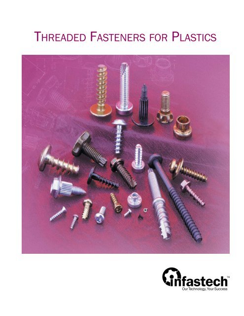
Threaded Fasteners for plastic - Infastech
Threaded Fasteners for plastic - Infastech
Threaded Fasteners for plastic - Infastech

You also want an ePaper? Increase the reach of your titles
YUMPU automatically turns print PDFs into web optimized ePapers that Google loves.
<strong>Threaded</strong> FasTeners For PlasTics
<strong>Threaded</strong> FasTeners For PlasTics<br />
<strong>Threaded</strong> <strong>Fasteners</strong> <strong>for</strong> Plastics vs. Standard Screws. . . . . . . . . . . . . . 4<br />
JoinTs in PlasTic<br />
Properties of Plastics . . . . . . . . . . . . . . . . . . . . . . . . . . . . . . . . . . . . . . . . 6<br />
Installing a <strong>Threaded</strong> Fastener in Plastics . . . . . . . . . . . . . . . . . . . . . . . 7<br />
Design Issues and Fastener Selection . . . . . . . . . . . . . . . . . . . . . . . . . . 8<br />
Fastener Selection Chart . . . . . . . . . . . . . . . . . . . . . . . . . . . . . . . . . . . .10<br />
<strong>Threaded</strong> FasTeners For ThermoPlasTics<br />
Delta PT ® <strong>Fasteners</strong> . . . . . . . . . . . . . . . . . . . . . . . . . . . . . . . . . . . . . . . .11<br />
PT ® <strong>Fasteners</strong> . . . . . . . . . . . . . . . . . . . . . . . . . . . . . . . . . . . . . . . . . . . . .13<br />
DST <strong>Fasteners</strong> . . . . . . . . . . . . . . . . . . . . . . . . . . . . . . . . . . . . . . . . . . . . .16<br />
Plastite ® 48 <strong>Fasteners</strong> . . . . . . . . . . . . . . . . . . . . . . . . . . . . . . . . . . . . . .18<br />
Plastite ® 45 <strong>Fasteners</strong> . . . . . . . . . . . . . . . . . . . . . . . . . . . . . . . . . . . . . .21<br />
<strong>Threaded</strong> FasTeners For ThermoseT PlasTics<br />
Duro-PT ® <strong>Fasteners</strong>. . . . . . . . . . . . . . . . . . . . . . . . . . . . . . . . . . . . . . . . . 24<br />
oTher <strong>Threaded</strong> FasTening soluTions<br />
Powergrip ® <strong>Fasteners</strong> <strong>for</strong> Layered Assemblies . . . . . . . . . . . . . . . . . . . 27<br />
PlasTORX ® <strong>Fasteners</strong> <strong>for</strong> Molded Assemblies. . . . . . . . . . . . . . . . . . . .28<br />
Perma-Nut ® <strong>Threaded</strong> Inserts . . . . . . . . . . . . . . . . . . . . . . . . . . . . . . . .30<br />
Other <strong>Threaded</strong> <strong>Fasteners</strong> <strong>for</strong> Plastics . . . . . . . . . . . . . . . . . . . . . . . . .34<br />
TORX PLUS ® Drive System . . . . . . . . . . . . . . . . . . . . . . . . . . . . . . . . . . .35<br />
deFiniTions<br />
Glossary. . . . . . . . . . . . . . . . . . . . . . . . . . . . . . . . . . . . . . . . . . . . . . . . . .36<br />
FasTeners For PlasTics imProve assembly & PerFormance<br />
Case Histories . . . . . . . . . . . . . . . . . . . . . . . . . . . . . . . . . . . . . . . . . . . . . 37<br />
FasTening & assembly soluTions For PlasTic aPPlicaTions
FasTening & assembly soluTions For PlasTic aPPlciaTions<br />
Plastics continue to open up a world of<br />
design opportunities, yet present some<br />
unique fastening problems. Whether<br />
you’re fastening <strong>plastic</strong> to <strong>plastic</strong> or<br />
<strong>plastic</strong> to another material, <strong>Infastech</strong><br />
offers a wide selection of high-<br />
per<strong>for</strong>mance fasteners engineered to<br />
meet the requirements of your<br />
application.<br />
selecTing The righT FasTener<br />
With thousands of different polymers<br />
available today, there can be no absolute<br />
guidelines to follow when fastening these<br />
materials. Laboratory testing of fasteners in<br />
the subject material is the only way to<br />
determine if acceptable per<strong>for</strong>mance levels<br />
can be achieved.<br />
For maximum per<strong>for</strong>mance, a fastener should<br />
be selected early in the design process.<br />
<strong>Infastech</strong> applications engineers are available<br />
to help you every step of<br />
the way, from selection and testing to<br />
boss design.<br />
Why use sPecial FasTeners For PlasTics?<br />
Each type of <strong>plastic</strong> has its own set of<br />
per<strong>for</strong>mance issues, such as ductility, thermal<br />
expansion and clamp retention. Selecting a<br />
fastener that can best match these<br />
requirements is critical to the overall<br />
per<strong>for</strong>mance of an application.<br />
Type B, type AB and other standard fasteners,<br />
with wide flank angles and shallow threads,<br />
were designed <strong>for</strong> use in sheet metal and can<br />
not meet the dynamic requirements of<br />
<strong>plastic</strong>s.<br />
oPTimal PerFormance<br />
<strong>Fasteners</strong> specially designed <strong>for</strong> <strong>plastic</strong>s can<br />
optimize per<strong>for</strong>mance in specific types of<br />
materials. By selecting the proper fastener,<br />
you may obtain:<br />
• Higher strip-out torque values<br />
• Increased resistance to loosening<br />
• Higher pull-out values<br />
reduced in-Place cosTs<br />
Proper fastener selection may allow the use of<br />
thinner bosses and eliminate the need <strong>for</strong><br />
supplementary locking devices. This can<br />
reduce in-place costs through:<br />
• Reduced material usage<br />
• Reduced cycling times<br />
• Elimination of inserts and adhesives<br />
• Streamlined assembly
Standard<br />
Fastener<br />
Typical Boss Design<br />
<strong>for</strong> Standard Screw<br />
<strong>Fasteners</strong> For Pl astic vs. standard scre ws<br />
Special Fastener<br />
<strong>for</strong> Plastics<br />
Typical Boss Design<br />
<strong>for</strong> Fastener <strong>for</strong><br />
Plastics<br />
MØ 1 MØ2<br />
mØ1<br />
Standard<br />
Fastener<br />
R 1<br />
R 2<br />
30°<br />
15°<br />
60°<br />
S<br />
CM 1<br />
mØ 1<br />
CM 1<br />
FRAD 1<br />
60°<br />
CM 2<br />
CM 2<br />
mØ 2<br />
Standard Fastener<br />
FRAD 2<br />
30°<br />
30° – 48°<br />
mØ 2<br />
2 /3S<br />
Special Fastener<br />
<strong>for</strong> Plastics<br />
Special Fastener <strong>for</strong> Plastic<br />
FRAD = 0.500R<br />
FRAD = 0.259R<br />
narroW Thread ProFiles maximize PerFormance<br />
Type B, type AB and other standard fasteners have a wide<br />
thread profile (also called flank angle) of 60°.<br />
Special fasteners <strong>for</strong> <strong>plastic</strong>s have special thread profiles to<br />
meet the needs of these unique materials. These narrower<br />
thread profiles, ranging from 30° to 48°, reduce radial stress<br />
and expansion. This in turn maximizes fastener per<strong>for</strong>mance.<br />
Because radial stress is reduced, special fasteners <strong>for</strong> <strong>plastic</strong>s<br />
allow the use of smaller bosses than standard screws, as shown<br />
at left. Using smaller bosses can reduce your overall costs<br />
through decreased material usage and molding cycle times.<br />
increased resisTance To Pull-ouT<br />
In the illustrations at left, CM represents the area subjected to<br />
shear when an axial load is applied.<br />
Because the special fastener <strong>for</strong> <strong>plastic</strong>s has a smaller minor<br />
diameter (mø) and a higher thread profile, it contains a larger<br />
volume of material (CM) and has a larger axial shear area.<br />
This greater area of thread engagement means the special<br />
fastener <strong>for</strong> <strong>plastic</strong>s is more resistant to pull-out.<br />
loWered radial sTress PrevenTs boss damage<br />
Radial <strong>for</strong>ce (FRAD) is an undesirable <strong>for</strong>ce since it creates<br />
outward stress and can damage the boss.<br />
Although the same volume of material is displaced between the<br />
60° thread and the 30° thread, the<br />
radial <strong>for</strong>ce generated by the 30°<br />
thread is approximately one-half that<br />
of the 60° thread.<br />
In the photo at right, the <strong>plastic</strong> boss<br />
with a 60° thread fastener shows radial<br />
stress and subsequent damage. The<br />
<strong>plastic</strong> boss with a special fastener <strong>for</strong><br />
<strong>plastic</strong>s shows reduced radial stress.<br />
Standard<br />
Fastener<br />
Special<br />
Fastener <strong>for</strong><br />
Plastics<br />
5
t h e P r o P e r t i e s o F P l a s t i c s<br />
The fastening per<strong>for</strong>mance of <strong>plastic</strong>s<br />
is affected by several factors:<br />
• Flexural modulus (stiffness of<br />
material)<br />
• Filler and/or rein<strong>for</strong>cement content<br />
(amount of glass, etc. added to<br />
material)<br />
• Thermal expansion rate<br />
• Creep rate<br />
Tensile Strength<br />
Clamp Load (lbs/in)<br />
6<br />
-40°<br />
73°<br />
Strain (% Elongation)<br />
Time (min.)<br />
170°<br />
250°<br />
Flexural modulus<br />
Flexural modulus is the best indicator of how a <strong>plastic</strong> will respond<br />
to fasteners. Generally, the lower the flexural modulus, the more<br />
the material will flow and allow the <strong>for</strong>mation of threads.<br />
Thermo<strong>plastic</strong>s with a higher flexural modulus also allow the<br />
<strong>for</strong>mation of threads, but usually require a fastener with a low<br />
helix angle to avoid excessive drive torque.<br />
Plastics with a high flexural modulus, including thermosets, are<br />
too stiff <strong>for</strong> thread <strong>for</strong>ming and will require thread-cutting fasteners.<br />
There are definite exceptions to these guidelines which can<br />
adversely affect fastening per<strong>for</strong>mance. Involve our application<br />
specialists early in the design process to maximize joint reliability.<br />
The eFFecTs oF Fillers on FasTening<br />
Fillers and rein<strong>for</strong>cements change one or more properties of the<br />
thermo<strong>plastic</strong>. They can also affect fastening per<strong>for</strong>mance.<br />
For example, impact-resistant resins tend to act more ductile<br />
than their flexural modulus would indicate. Lubricants added <strong>for</strong><br />
molding, such as silicone, tend to reduce drive torque but can<br />
negatively affect clamp load.<br />
Again, it is important to test your application early in the design<br />
process to ensure optimal per<strong>for</strong>mance.<br />
Thermal exPansion raTe<br />
The stress/strain curve <strong>for</strong> thermo<strong>plastic</strong>s is very temperature<br />
dependent. Plastics expand much faster than metals do when<br />
subjected to the same thermal loading.<br />
Since very few joints operate at constant temperatures, thermal<br />
expansion or contraction is virtually universal. This will affect<br />
clamp load. However, this is only a problem if the application<br />
uses materials with dissimilar expansion rates and the<br />
temperature change is significant.<br />
creeP raTe<br />
Under load or heat all <strong>plastic</strong>s will creep, or permanently<br />
de<strong>for</strong>m. Creep will, in turn, cause a loss in clamp load. The chart<br />
at left demonstrates the loss of clamp load, at a stable<br />
temperature, over 64 hours <strong>for</strong> a #8 Plastite ® fastener driven<br />
into acetal resin.<br />
However, creep can be compensated <strong>for</strong> in joint design through a<br />
variety of methods. See page 9 <strong>for</strong> more details.
1. Thread-<strong>for</strong>ming<br />
begins<br />
2. Screw head in contact<br />
with <strong>plastic</strong>; clamp<br />
load generated<br />
3. Strip-out torque level<br />
met or exceeded;<br />
boss damage occurs<br />
TORQUE (lb/in)<br />
TORQUE<br />
safety margin<br />
clamp<br />
thread-<strong>for</strong>ming<br />
strip<br />
(10 lbs/in)<br />
seating<br />
drive<br />
(5 lbs/in)<br />
Standard Fastener<br />
2:1 strip-to-drive<br />
ratio<br />
i n s t a l l i n g a F a s t e n e r i n P l a s t i c<br />
strip/failure torque<br />
3.<br />
1.<br />
clamping<br />
load<br />
2.<br />
thread-<strong>for</strong>ming<br />
torque<br />
PENETRATION DEPTH<br />
strip<br />
(28 lbs/in)<br />
seating<br />
drive<br />
(7 lbs/in)<br />
Special Fastener<br />
<strong>for</strong> Plastic<br />
4:1 strip-to-drive<br />
ratio<br />
Thread-Forming and sTriPPing Torque<br />
Because friction increases as penetration increases, the<br />
differential between the thread-<strong>for</strong>ming torque and the strip<br />
(failure) torque must be maximized.<br />
Proper seating torque varies from application to application,<br />
so contact an <strong>Infastech</strong> applications engineer <strong>for</strong> assistance.<br />
drive-To-sTriP raTio<br />
As demonstrated in the chart to the left – based on testing –<br />
the fastener <strong>for</strong> <strong>plastic</strong> has a much higher drive-to-strip ratio, so<br />
the joint is less likely to be damaged during installation.<br />
The standard screw has a safety margin of only 3.5 lbs/in. The<br />
special fastener <strong>for</strong> <strong>plastic</strong> has a safety margin of 12 lbs/in.<br />
Note: The chosen seating torque was 65% of the failure torque, based on testing.<br />
inFluence oF driver sPeed<br />
Increased drive gun speed can negatively affect the quality of<br />
the joint.<br />
During installation, as the RPMs<br />
increase, so does the amount of heat<br />
that is generated. Too much heat can<br />
break down the <strong>plastic</strong> and lower the<br />
failure torque level.<br />
deTermining ProPer seaTing Torque<br />
<strong>Infastech</strong> can run complete tests on your application to<br />
determine your optimal fastening solution, including fastener<br />
selection, joint design and seating torque.<br />
For a recommendation on how to run your own tests to<br />
determine proper seating torque, please see page 9.<br />
7
d e s i g n i s s u e s a n d F a s t e n e r s e l e c t i o n<br />
There are several factors which can<br />
affect a fastener’s ability to achieve<br />
satisfactory per<strong>for</strong>mance, including:<br />
• Pilot hole diameter<br />
• Length of engagement<br />
• Boss design<br />
Though product design may dictate<br />
certain restrictions, laboratory testing<br />
will determine the proper combination of<br />
these factors <strong>for</strong> your application.<br />
8<br />
length of<br />
engage.<br />
lead<br />
threads<br />
hØ<br />
1 /2 L<br />
CB d<br />
L<br />
Thread engagemenT & PiloT hole diameTer<br />
Thread engagement is the amount of thread flank depth that is<br />
filled by the application material. It is often expressed as a<br />
percentage. A hole diameter equal to the major diameter of the<br />
threads would have a thread engagement of 0%. In moderately<br />
stiff materials, you should start with a hole size that provides<br />
75% to 80% thread engagement.<br />
A hole that creates a thread engagement of over 100% does not<br />
improve per<strong>for</strong>mance. It will, however, increase required drive<br />
torque, because the walls of the hole must expand to make<br />
room <strong>for</strong> the screw.<br />
If the hole size is fixed, you will need to adjust the thread style<br />
or length of engagement to reach the appropriate per<strong>for</strong>mance<br />
requirements.<br />
Each fastener <strong>for</strong> <strong>plastic</strong>s has its own parameters. For optimal<br />
per<strong>for</strong>mance, contact an <strong>Infastech</strong> applications engineer <strong>for</strong><br />
assistance.<br />
lengTh oF engagemenT<br />
Length of engagement is the measurement of full-sized fastener<br />
threads engaged in the nut material. The length of the lead<br />
thread (usually about one-half the fastener diameter) is not<br />
counted in the length of engagement, since its reduced size<br />
minimizes any per<strong>for</strong>mance benefits.<br />
Length of engagement is often expressed in relationship to the<br />
nominal diameter of the screw; e.g. 2 to 2-1/2 diameters of<br />
engagement.<br />
boss design<br />
Drafted holes ease molding in thermo<strong>plastic</strong>s, but can affect<br />
thread engagement. Always utilize the minimum amount of draft<br />
possible to retain good mold function.<br />
Generally, the nominal hole size (hØ) is calculated at a depth<br />
equal to half of the fastener’s total length of engagement (L),<br />
not including the counterbore.<br />
Follow the specific boss design recommendations listed <strong>for</strong> each<br />
threaded fastener.
TORQUE<br />
TORQUE<br />
1.<br />
TIME<br />
Through Hole Signature Curve<br />
1.<br />
2.<br />
2.<br />
TIME<br />
Blind Hole Signature Curve<br />
1 – Peak Drive Torque: level at which<br />
the materials are drawn together<br />
and the fastener seats<br />
2 – Ultimate Torque: level at which the<br />
joint fails; usually from strip-out<br />
d e s i g n i s s u e s a n d F a s t e n e r s e l e c t i o n<br />
comPensaTing For The eFFecTs oF creeP in a JoinT<br />
As stated previously, under load or heat, all <strong>plastic</strong>s will creep.<br />
There are several methods to compensate <strong>for</strong>, or reduce, the<br />
effects of creep in a joint.<br />
• Reduce the stress at the bearing surface by one or more of<br />
the following:<br />
– increase the fastener head diameter<br />
– add a flat washer<br />
– reduce the clearance hole diameter<br />
– reduce initial clamp load at assembly<br />
• Add a spring element to the joint such as a helical and flat<br />
washer combination<br />
• Add a metal sleeve in the clamped component to carry some<br />
of the clamp load<br />
• Use a shoulder bolt to transfer the load to the nut member<br />
• Increase stiffness of <strong>plastic</strong> by adding a filler or changing the<br />
base resin<br />
TesTing To deTermine ProPer seaTing Torque<br />
The following are general recommendations only.<br />
1. Gather enough sample applications to generate a statistically<br />
significant sampling – a minimum of 30 per specific joint<br />
condition. These samples must include all components in the<br />
joint stack-up such as clamping components, nut members<br />
and fasteners.<br />
2. Use a drive gun that can torque the fasteners to failure and has<br />
the same RPM as the drive gun that will be used in production.<br />
3. Use a torque measuring device and a strip chart or graph and<br />
capture the peak drive torque and ultimate torque values.<br />
Drive the fasteners to failure. Calculate the average of the<br />
peak drive values and of the ultimate torque values.<br />
4. Next calculate the average of these two resulting values. This<br />
is the target seating torque. Factor a value of ±10% <strong>for</strong> gun<br />
accuracy. Compare this torque window to +3SD (standard<br />
deviation) of the average drive torque value and -3SD of the<br />
average ultimate torque value. If there is no overlap of the<br />
two regions, the torque window will allow the fasteners to be<br />
seated without failure at assembly. If there is overlap in either<br />
of the two regions, a redesign of the joint is warranted.<br />
For assistance, please contact an <strong>Infastech</strong> applications<br />
engineer.<br />
9
s e l e c t i n g t h e r i g h t t h r e a d e d F a s t e n e r<br />
The following chart is intended only as a starting point in the selection of fasteners. The fastener must be<br />
matched to the properties of the material. Drive to strip ratios, clamp retention, and other per<strong>for</strong>mance issues<br />
are directly affected by the fastener you choose. Please contact an <strong>Infastech</strong> applications engineer <strong>for</strong><br />
assistance in selecting the optimum fastener <strong>for</strong> your design.<br />
Included Materials<br />
THERMOPLASTICS<br />
10<br />
ductile<br />
moderate<br />
stiff<br />
THERMOSETS<br />
ALL PLASTICS<br />
Flexural<br />
Modulus<br />
(PSI) Fastening Solution<br />
Polyethylene (PE) 150,000 Delta PT ® fastener, PT ® fastener, or<br />
Polypropylene (PP) 200,000<br />
DST fastener<br />
Polycarbonate (PC) 340,000<br />
ABS, 0-20% glass fill 350,000<br />
Polyamide 66 (PA) 350,000<br />
Acetal (AC) 400,000<br />
Polystyrene (PS) 430,000<br />
Polypropylene, 40% talc fill (PP40) 500,000<br />
Polypheylene Sulfide 550,000<br />
ABS, 20% glass fill 650,000<br />
Polyamide 66, 12% glass fill 800,000<br />
Polycarbonate, 20% glass fill (PC20) 850,000<br />
Polycarbonate, 30% glass fill (PC30) 1,100,000<br />
Polybutylene Terephthalates 30% glass fill (PBT30) 1,100,000<br />
Polyamide 66, 30% glass fill (PA30) 1,200,000<br />
Liquid Crystal Polymer (LCP) 1,400,000<br />
Polyphenylene Sulfide, 40% fill (PPS40) 1,700,000<br />
Phenolic, 20% glass fill 1,750,000<br />
Polyester, 50% glass fill 2,100,000<br />
Delta PT fastener, PT fastener, twin helix<br />
Plastite ® fastener, or DST fastener<br />
Delta PT fastener,<br />
twin helix Plastite 48 fastener,<br />
or PT fastener<br />
Delta PT fastener,<br />
single-helix Plastite 48 or 45 fastener,<br />
or PT fastener<br />
Duro-PT ® thread-cutting fastener<br />
TYPE OF APPLICATION FASTENING SOLUTION<br />
Plastic or other materials to thin metal Powergrip ® fasteners<br />
Molded assemblies PlasTORX ® fasteners<br />
Extremely thin materials where a nut member is required Perma-Nut ® inserts<br />
Rapid assembly of <strong>plastic</strong> and/or metal components Rivscrew ® threaded rivets
Delta PT ® fasteners are engineered<br />
to provide maximum per<strong>for</strong>mance in<br />
a wide range of thermo<strong>plastic</strong>s. The<br />
improved design results in a<br />
stronger fastener that creates<br />
optimal material flow during<br />
installation, providing higher<br />
per<strong>for</strong>mance, better clamp loads<br />
and increased joint life.<br />
Sizes • Delta PT 14 – 70 (1.4mm –<br />
7.0mm); other sizes may be available<br />
Head Styles • Can be used with any<br />
head design<br />
Specials • Shoulder screws, sems,<br />
double end studs, collar studs; others<br />
as required<br />
Drive Systems • TORX PLUS ® sPeciFicaTions<br />
Drive is<br />
recommended to facilitate the proper<br />
amount of torque transfer required <strong>for</strong><br />
<strong>for</strong>ming threads. Other styles also<br />
available.<br />
aPPlicaTions<br />
Thermo<strong>plastic</strong>s with a flexural modulus<br />
up to 1,400,000 p.s.i.<br />
d e l t a P t ® t h r e a d - F o r m i n g F a s t e n e r s<br />
optimal<br />
material<br />
flow<br />
Delta PT Fastener<br />
Key advanTages<br />
• Provides optimal per<strong>for</strong>mance in all types of thermo<strong>plastic</strong>s<br />
• Provides increased torsional and tensile strength over PT<br />
fasteners<br />
• Provides high strength and in-place reliability<br />
• Can achieve higher clamp loads and seating torques<br />
FeaTures & beneFiTs<br />
Flank geometry engineered to provide better material flow<br />
during installation<br />
• Provides high flank engagement<br />
• Can achieve higher clamp loads and seating torques<br />
• Optimizes material flow<br />
• May permit use of shorter fasteners and/or smaller<br />
diameters, if necessary<br />
Larger fastener cross-section<br />
• Increases shear area and fastener strength<br />
• Offers increased fatigue life<br />
• Provides increased torsional and tensile strength<br />
engineered<br />
flank<br />
geometry<br />
Optimized pitch<br />
• Allows high clamp load with smaller contact pressure<br />
• Minimizes radial stress<br />
11
d e l t a P t ® t h r e a d - F o r m i n g F a s t e n e r s<br />
p<br />
12<br />
mØ<br />
MØ<br />
increased sTrengTh<br />
Delta PT fastener<br />
PT fastener<br />
dimensional daTa<br />
With its extended core diameter and<br />
optimum thread design, the Delta PT<br />
fastener offers a longer fatigue life than<br />
the PT fastener. The Delta PT design<br />
provides better thread engagement and,<br />
there<strong>for</strong>e, better conditions against<br />
stress fractures of the thread flank.<br />
The chart above demonstrates that the<br />
Delta PT fastener provides greater<br />
resistance against screw breakage than<br />
the PT fasteners under in-service loads.<br />
p<br />
Thread<br />
Pitch<br />
(mm)<br />
MØ<br />
Major<br />
Dia.<br />
(mm)<br />
mØ<br />
Minor<br />
Dia.<br />
(mm)<br />
Nom.<br />
Metric<br />
Size<br />
Size<br />
Delta PT 14 M1.4 0.573 1.4 0.928<br />
Delta PT 16 M1.6 0.641 1.6 1.073<br />
Delta PT 18 M1.8 0.709 1.8 1.218<br />
Delta PT 20 M2.0 0.78 2.0 1.4<br />
Delta PT 22 M2.2 0.85 2.2 1.5<br />
Delta PT 25 M2.5 0.95 2.5 1.7<br />
Delta PT 30 M3.0 1.12 3.0 2.1<br />
Delta PT 35 M3.5 1.29 3.5 2.5<br />
Delta PT 40 M4.0 1.46 4.0 2.8<br />
Delta PT 45 M4.5 1.63 4.5 3.2<br />
Delta PT 50 M5.0 1.80 5.0 3.5<br />
Delta PT 60 M6.0 2.14 6.0 4.3<br />
Delta PT 70 M7.0 2.48 7.0 5.0<br />
R = 0.1<br />
Cycle stress; breakage of<br />
the fastener cross section<br />
boss design recommendaTions<br />
*PT fastener standards are true metric sizes.<br />
The criteria <strong>for</strong> optimum<br />
hole diameter is to<br />
obtain the maximum<br />
clamp load during the<br />
installation process. A<br />
good starting point in<br />
determining the proper<br />
hole diameter is<br />
d = 0.8 x d1 Specific applications<br />
will require some<br />
modifications to allow<br />
<strong>for</strong> the flexural modulus<br />
of the material, molding<br />
conditions, mold tool design, feed distance from gate, weld<br />
lines, structural heterogeneity and amount of reground material.<br />
In order to ensure optimal per<strong>for</strong>mance, we recommend testing<br />
on initial samples. Please contact an <strong>Infastech</strong> applications<br />
engineer <strong>for</strong> assistance.<br />
Decorah Operations<br />
1-800-544-6117<br />
www.infastech.com<br />
Elco ® , iForm and <strong>Infastech</strong> are trademarks of <strong>Infastech</strong> Intellectual Properties Pte Ltd. TORX PLUS ®<br />
is a registered trademark of Acument Intellectural Properties LLC. Avdel ® is a registered trademark of<br />
Avdel UK Ltd. PT ® is a registered trademark of EJOT Verbindungstechnik & Co. KG.<br />
©2011 <strong>Infastech</strong> Intellectual Properties Pte Ltd. All rights reserved.
With a high thread profile and<br />
recessed thread root, the PT ®<br />
fastener provides increased thread<br />
engagement with minimal stress on<br />
the boss. It provides optimal<br />
per<strong>for</strong>mance in a wide range of<br />
thermo<strong>plastic</strong>s.<br />
Sizes • K15 – K100 in diameter<br />
up to 127mm under head<br />
Head Styles • Can be used with any<br />
head design<br />
Specials • Shoulder screws, sems,<br />
double end studs, collar studs; others<br />
as required<br />
Drive Systems • TORX PLUS ® sPeciFicaTions<br />
Drive is<br />
recommended to facilitate the proper<br />
amount of torque transfer required <strong>for</strong><br />
<strong>for</strong>ming threads. Other styles also<br />
available.<br />
aPPlicaTions<br />
Thermo<strong>plastic</strong>s with a flexural modulus<br />
up to 1,400,000 p.s.i.<br />
P t ® t h r e a d - F o r m i n g F a s t e n e r s<br />
narrow<br />
thread<br />
pitch<br />
Key advanTages<br />
• Optimizes per<strong>for</strong>mance in all types of thermo<strong>plastic</strong>s<br />
• Provides maximum resistance to back-out and pull-out<br />
• Minimizes boss failure<br />
• Increases product reliability<br />
FeaTures & beneFiTs<br />
Narrow 30° thread profile minimizes radial expansion and<br />
stress in boss<br />
• Permits use of thinner bosses, which can reduce cycling times<br />
and material usage<br />
• Reduces back-out caused by relaxation<br />
• Increases load-carrying capability through increased thread<br />
engagement<br />
• Can be used in repeat assembly operations<br />
Optimum thread pitch allows deeper thread engagement<br />
• Provides increased pull-out values<br />
• Optimizes non-reversibility<br />
• Balances load ratio between <strong>plastic</strong> and screw<br />
Recessed thread root allows optimal material flow<br />
• Minimizes installation torque<br />
• Improves clamp load<br />
• Minimizes potential of boss cracking<br />
Round body evenly distributes surface contact between<br />
application and screw<br />
• Improves load ratio<br />
• Reduces high points of stress on the boss<br />
Through hardened to Rc 33-39<br />
PT Fastener<br />
30°<br />
thread<br />
profile<br />
recessed<br />
thread<br />
root<br />
13
P t ® t h r e a d - F o r m i n g F a s t e n e r s<br />
p<br />
14<br />
dimensional daTa<br />
Nom.<br />
Size<br />
Metric<br />
Size<br />
hole sizes Per PercenTage oF Thread engagemenT<br />
Size<br />
mØ<br />
MØ<br />
p<br />
Thread<br />
Pitch<br />
(mm)<br />
*PT fastener standards are true metric sizes.<br />
MØ<br />
Major<br />
Diameter<br />
(mm)<br />
mØ<br />
Minor<br />
Diameter<br />
(mm)<br />
K15 M1.5 0.67 1.50 0.89<br />
K18 M1.8 0.80 1.80 1.04<br />
K22 M2.2 0.98 2.20 1.25<br />
K25 M2.5 1.12 2.50 1.40<br />
K30 M3.0 1.34 3.00 1.66<br />
K35 M3.5 1.57 3.50 1.91<br />
K40 M4.0 1.79 4.00 2.17<br />
K50 M5.0 2.24 5.00 2.68<br />
K60 M6.0 2.69 6.00 3.19<br />
K70 M7.0 3.14 7.00 3.70<br />
K100 M10.0 4.49 10.00 5.23<br />
100% 90% 80% 70% 60% 50% 40%<br />
mm in. mm in. mm in. mm in. mm in. mm in. mm in.<br />
K15 1.21 .048 1.24 .049 1.27 .050 1.30 .051 1.33 .052 1.35 .053 1.38 .054<br />
K18 1.40 .055 1.44 .057 1.48 .058 1.52 .060 1.56 .061 1.60 .063 1.64 .065<br />
K22 1.66 .065 1.71 .067 1.77 .070 1.82 .072 1.88 .074 1.93 .076 1.98 .078<br />
K25 1.85 .073 1.92 .076 1.98 .078 2.05 .081 2.11 .083 2.18 .086 2.24 .088<br />
K30 2.18 .086 2.26 .089 2.34 .092 2.42 .095 2.51 .099 2.59 .102 2.67 .105<br />
K35 2.50 .098 2.60 .102 2.70 .106 2.80 .110 2.90 .114 3.00 .118 3.10 .122<br />
K40 2.82 .111 2.94 .116 3.06 .120 3.17 .125 3.29 .130 3.41 .134 3.53 .139<br />
K50 3.46 .136 3.62 .142 3.77 .148 3.92 .155 4.08 .161 4.23 .167 4.39 .173<br />
K60 4.11 .162 4.30 .169 4.49 .177 4.68 .184 4.86 .192 5.05 .199 5.24 .206<br />
K80 5.40 .212 5.66 .223 5.92 .233 6.18 .243 6.44 .253 6.70 .264 6.96 .274<br />
K100 6.68 .263 7.02 .276 7.35 .289 7.68 .302 8.01 .315 8.34 .328 8.67 .341
P t ® t h r e a d - F o r m i n g F a s t e n e r s<br />
Laboratory testing and service applications have produced the<br />
general recommendations shown here. Specific applications<br />
may, however, require some modifications to allow <strong>for</strong>:<br />
• molding conditions • weld lines<br />
• mold tool design • structural heterogeneity<br />
• amount of reground material • feed distance from gate<br />
In order to ensure optimal per<strong>for</strong>mance, we strongly<br />
recommend testing on initial samples.<br />
counTerbore size<br />
The width of the counterbore should be equal to the major<br />
diameter of the screw (d). The height of the counterbore should<br />
be 0.3 to 0.5 times the nominal screw diameter.<br />
PT FasTener boss design recommendaTions<br />
Hole Boss Length of<br />
Material<br />
Dia. Dia. Engagement<br />
ABS (acrylonitrile) 0.80 x d 2.00 x d 2.00 x d<br />
ASA (acrylonitrile styrene acrylic) 0.78 x d 2.00 x d 2.00 x d<br />
Nylon: PA6 (polyamide) 0.75 x d 1.85 x d 1.70 x d<br />
Nylon: PA-GF30 0.80 x d 2.00 x d 1.90 x d<br />
Nylon: PA6.6 0.75 x d 1.85 x d 1.70 x d<br />
Nylon: PA6.6-GF30 0.82 x d 2.00 x d 1.80 x d<br />
PBT (polybutylene terephthalate) 0.75 x d 1.85 x d 1.70 x d<br />
PBT-GF30 0.80 x d 1.80 x d 1.70 x d<br />
PC (polycarbonate) 0.85 x d 2.50 x d 2.20 x d<br />
PC-GF30 0.85 x d 2.20 x d 2.00 x d<br />
PE soft (polyethylene) 0.70 x d 2.00 x d 2.00 x d<br />
PE hard (polyethylene) 0.75 x d 1.80 x d 1.80 x d<br />
PET (polyethylene terephthalate) 0.75 x d 1.85 x d 1.70 x d<br />
PET-GF30 0.80 x d 1.80 x d 1.70 x d<br />
POM acetal 0.75 x d 1.95 x d 2.00 x d<br />
PP (polypropylene) 0.70 x d 2.00 x d 2.00 x d<br />
PPO (polyphenylene oxide) 0.85 x d 2.50 x d 2.20 x d<br />
PS (polystyrene) 0.80 x d 2.00 x d 2.00 x d<br />
PVC hard (polyvinyle chloride) 0.80 x d 2.00 x d 2.00 x d<br />
SAN (styrene acrylonitrile) 0.77 x d 2.00 x d 1.90 x d<br />
counterbore depth<br />
0.3d to 0.5d<br />
boss Ø<br />
1.8d to 2.5d<br />
boss design examPle<br />
Material: ABS<br />
To calculate boss size based on<br />
fastener size:<br />
Screw size: K40<br />
Major diameter: 4mm<br />
Boss O.D. = 2 X screw dia.<br />
2 X 4mm = 8mm<br />
Boss I.D. = .8 X screw dia.<br />
.8 X 4mm = 3.2mm<br />
Min. length of eng. = 2 X screw dia.<br />
2 X 4mm = 8mm<br />
To calculate screw size based on<br />
(predetermined) boss size:<br />
Boss O.D.: 8mm<br />
Boss I.D.: 3.2mm<br />
Screw dia. = Boss O.D. ÷ 2<br />
8mm ÷ 2 = 4mm<br />
d<br />
hole Ø<br />
.70d to .85d<br />
Decorah Operations<br />
1-800-544-6117<br />
www.infastech.com<br />
The in<strong>for</strong>mation in this manual is not to be considered<br />
a specification.<br />
Elco ® , iForm and <strong>Infastech</strong> are trademarks of <strong>Infastech</strong><br />
Intellectual Properties Pte Ltd. TORX PLUS ® is a registered<br />
trademark of Acument Intellectural Properties LLC. Avdel ® is a<br />
registered trademark of Avdel UK Ltd. PT ® is a registered<br />
trademark of EJOT Verbindungstechnik & Co. KG.<br />
©2011 <strong>Infastech</strong> Intellectual Properties Pte Ltd.<br />
All rights reserved.
d s t t h r e a d - F o r m i n g F a s t e n e r s<br />
The high thread height and wide<br />
thread spacing of the DST (Dual-<br />
Spaced Thread) fastener allows<br />
increased thread engagement in<br />
softer thermo<strong>plastic</strong>s, increasing<br />
resistance to pull-out and improving<br />
product per<strong>for</strong>mance.<br />
Sizes • #2 to 5/16 (M2.5 – M8.0)<br />
Head Styles • Pan, hex, flat, oval, hex<br />
washer<br />
Point Styles • Blunt, gimlet, pilot<br />
Drive Systems • Can use any system,<br />
including TORX PLUS ® sPeciFicaTions<br />
Drive<br />
aPPlicaTions<br />
Thermo<strong>plastic</strong>s with a flexural modulus<br />
up to 600,000 p.s.i.<br />
16<br />
two<br />
thread<br />
profiles<br />
DST Fastener<br />
Key advanTages<br />
• Per<strong>for</strong>ms well in softer thermo<strong>plastic</strong>s<br />
high<br />
thread<br />
height<br />
various point styles<br />
available<br />
FeaTures & beneFiTs<br />
High thread with a 30° flank angle to reduce radial stress in<br />
the boss<br />
• Requires lower driving torque<br />
• Reduces cracking of boss<br />
• Allows use of smaller bosses<br />
Smaller minor diameter than standard screws allows greater<br />
shear area<br />
• Increases thread engagement<br />
• Increases resistance to pull-out<br />
Shank slot <strong>for</strong> thread-cutting can be added. Please contact an<br />
<strong>Infastech</strong> applications engineer <strong>for</strong> appropriate dimensional<br />
in<strong>for</strong>mation.
p<br />
mØ<br />
LØ<br />
HØ<br />
d s t t h r e a d - F o r m i n g F a s t e n e r s<br />
dimensional daTa – inch<br />
Screw<br />
Size<br />
p<br />
Thd.<br />
Pitch<br />
(per in.)<br />
boss design recommendaTions<br />
boss O.D.<br />
HØ<br />
High<br />
Thd.<br />
Dia.<br />
LØ<br />
Low<br />
Thd.<br />
Dia.<br />
mØ<br />
Ref.<br />
Minor<br />
Dia.<br />
#5 20 .119 - .125 .100 .073<br />
#6 19 .135 - .145 .108 .080<br />
#7 19 .148 - .158 .130 .090<br />
#8 18 .160 - .170 .130 .095<br />
#10 16 .185 - .195 .145 .105<br />
#12 16 .210 - .220 .167 .125<br />
#13 16 .220 - .230 .180 .132<br />
1/4" 15 .250 - .260 .200 .165<br />
9/32" 16 .275 - .285 .230 .188<br />
5/16" 14 .307 - .317 .250 .208<br />
HØ<br />
d<br />
The recommended hole size (d) can be found in the chart to the<br />
right.<br />
The length of engagement (le) should be 3 times the high thread<br />
diameter (see chart above).<br />
Counterbore depth is 1 to 2 times the thread pitch length (see<br />
chart above). Counterbore depth is equal to the high thread<br />
diamter (HØ).<br />
The boss O.D. should be at least 2 times the high thread<br />
diameter.<br />
2p<br />
le<br />
dimensional daTa – meTric<br />
Screw<br />
Size<br />
p<br />
Thd.<br />
Pitch<br />
HØ<br />
High<br />
Thd.<br />
Dia.<br />
LØ<br />
Low<br />
Thd.<br />
Dia.<br />
mØ<br />
Ref.<br />
Minor<br />
Dia.<br />
3.5 1.34 3.43 - .3.68 2.74 2.0<br />
4.0 1.34 3.76 - 4.01 3.30 2.3<br />
4.2 1.41 4.06 - 4.32 3.30 2.4<br />
4.8 1.59 4.70 - 4.95 3.68 2.6<br />
5.3 1.59 5.03 - 5.33 3.81 2.9<br />
5.5 1.59 5.33 - 5.59 4.24 3.5<br />
6.0 1.59 5.84 - 6.10 4.83 3.7<br />
6.3 1.69 6.35 - 6.60 5.08 4.2<br />
7.2 1.59 6.98 - 7.24 5.84 4.8<br />
7.5 1.59 7.24 - 7.49 6.10 5.1<br />
8.0 1.81 7.80 - 6.35 6.35 5.3<br />
recommended hole sizes<br />
Screw<br />
Size<br />
(inch)<br />
Hole<br />
Size (d)<br />
(in)<br />
#5 .099<br />
#6 .110<br />
#7 .125<br />
#8 .128<br />
#10 .144<br />
#12 .166<br />
#13 .180<br />
1/4" .201<br />
9/32" .234<br />
5/16" .250<br />
Decorah Operations<br />
1-800-544-6117<br />
www.infastech.com<br />
Screw<br />
Size<br />
(metric)<br />
Hole<br />
Size (d)<br />
(mm)<br />
3.5 2.79<br />
4.0 3.17<br />
4.2 3.26<br />
4.8 3.65<br />
5.3 3.96<br />
5.5 4.21<br />
6.0 4.85<br />
6.3 5.10<br />
7.2 5.95<br />
7.5 6.14<br />
8.0 6.35<br />
NOTE: Recommended hole sizes <strong>for</strong> DST<br />
thread-cutting fasteners are not shown.<br />
Please contact an <strong>Infastech</strong> applications<br />
engineer <strong>for</strong> assistance.<br />
Elco ® , iForm and <strong>Infastech</strong> are trademarks of <strong>Infastech</strong> Intellectual Properties Pte Ltd. TORX PLUS ®<br />
is a registered trademark of Acument Intellectural Properties LLC. Avdel ® is a registered trademark of<br />
Avdel UK Ltd.<br />
©2011 <strong>Infastech</strong> Intellectual Properties Pte Ltd. All rights reserved.<br />
17
P l a s t i t e ® 4 8 t h r e a d - F o r m i n g F a s t e n e r<br />
The Plastite ® 48 fastener combines<br />
a unique tri-lobular body with a 48°<br />
thread profile to maximize<br />
per<strong>for</strong>mance and reliability. Two<br />
thread-<strong>for</strong>ming styles are available<br />
to meet the specific requirements of<br />
a wide range of thermo<strong>plastic</strong>s.<br />
sPeciFicaTions<br />
Sizes • #00 – 5/16"; other sizes may<br />
be available upon request<br />
Head Styles • Can be used with any<br />
external or internal head designs; pan,<br />
hex washer, and flat styles standard<br />
Drive System • Can use any system,<br />
including TORX PLUS Drive<br />
Finish • As required<br />
aPPlicaTions<br />
Twin Helix Style • Thermo<strong>plastic</strong>s with<br />
a flexural modulus up to 850,000 p.s.i.<br />
Single Helix Style • Thermo<strong>plastic</strong>s<br />
with a flexural modulus between<br />
850,000 p.s.i. and 1,400,000 p.s.i.<br />
18<br />
steeper<br />
helix<br />
angle<br />
48°<br />
thread<br />
profile<br />
tri-roundular<br />
shank<br />
Twin-Helix Style Single-Helix Style<br />
Key advanTages<br />
• Reduces possibility of boss failure<br />
• Increases product reliability<br />
• Eliminates need <strong>for</strong> inserts and lock washers<br />
FeaTures & beneFiTs<br />
Plastite 48 <strong>Fasteners</strong><br />
Tri-roundular configuration allows displaced material to cold<br />
flow back into relief areas<br />
• Minimizes radial stress<br />
• Reduces possibility of boss failure<br />
• Eliminates need <strong>for</strong> inserts and lock<br />
washers<br />
• Allows design of thinner bosses<br />
48° thread profile allows threads to<br />
penetrate deeply into <strong>plastic</strong> material<br />
• Generates strong mating threads<br />
• Resists vibration loosening<br />
• Reduces probability of strip-out and pull-out<br />
Twin lead design and steep helix angle provides greater<br />
shear area in softer <strong>plastic</strong>s (with a flexural modulus up to<br />
850,000 p.s.i.)<br />
• Increases holding power<br />
• Allows faster seating of fastener<br />
shallower<br />
helix<br />
angle<br />
relief areas<br />
thread-<strong>for</strong>ming<br />
lobes<br />
Single lead design and narrow helix angle lowers drive torque<br />
and failure torque in stiffer thermo<strong>plastic</strong>s (with flexural<br />
modulus between 850,000 and 1,300,000 p.s.i.)<br />
• Creates less stress on the boss
dimensional daTa – inch sizes<br />
Nom.<br />
Size<br />
Thread<br />
Pitch<br />
(per inch)<br />
dimensional daTa – meTric sizes*<br />
P l a s t i t e ® 4 8 t h r e a d - F o r m i n g F a s t e n e r<br />
D †<br />
C Dimension<br />
max-min<br />
(in)<br />
C †<br />
† C dimension measured with Tri-Flute Micrometer<br />
D diameter measured with Standard Micrometer<br />
D Dimension<br />
max-min<br />
(in)<br />
Screw Length Tolerance<br />
under 3/4"<br />
(in)<br />
* Plastite 48 fasteners are not available in true metric sizes. The chart above provides nominal inch<br />
dimensions converted to millimeters.<br />
over 3/4"<br />
(in)<br />
#00 51 .0496 - .0466 .0475 - .0445 ±.015 ±.015<br />
#0 42 .0665 - .0635 .0635 - .0605 ±.015 ±.015<br />
#1 32 .081 - .078 .078 - .075 ±.030 ±.030<br />
#2 28 .092 - .086 .089 - .083 ±.030 ±.030<br />
#3 24 .110 - .104 .106 - .100 ±.030 ±.030<br />
#4 20 .127 - .121 .123 - .117 ±.030 ±.050<br />
#6 19 .147 - .141 .143 - .137 ±.030 ±.050<br />
#7 18 .166 - .160 .160 - .154 ±.030 ±.050<br />
#8 16 .185 - .179 .179 - .173 ±.030 ±.050<br />
#9 15 .199 - .193 .193 - .187 ±.030 ±.050<br />
#10 14 .212 - .206 .208 - .202 ±.030 ±.050<br />
#12 14 .232 - .226 .226 - .220 ±.030 ±.050<br />
1/4" 10 .276 - .270 .268 - .262 ±.050 ±.050<br />
5/16" 9 .345 - .335 .335 - .325 ±.050 ±.050<br />
*soft converted metric sizes<br />
C Dimension D Dimension Screw Length Tolerance<br />
Nom. Thread max-min<br />
max-min under 19.05mm over 19.05mm<br />
Size Pitch<br />
(mm)<br />
(mm)<br />
(mm)<br />
(mm)<br />
1.12 0.50 1.26 - 1.18 1.21 - 1.13 ±0.38 ±0.38<br />
1.59 0.60 1.69 - 1.61 1.61 - 1.54 ±0.38 ±0.38<br />
1.91 0.79 2.06 - 1.98 1.98 - 1.91 ±0.76 ±0.76<br />
2.26 0.91 2.34 - 2.18 2.26 - 2.11 ±0.76 ±0.76<br />
2.63 1.06 2.79 - 2.64 2.69 - 2.54 ±0.76 ±0.76<br />
3.12 1.27 3.23 - 3.07 3.12 - 2.97 ±0.76 ±1.27<br />
3.63 1.34 3.73 - 3.58 3.63 - 3.48 ±0.76 ±1.27<br />
4.06 1.41 4.22 - 4.06 4.06 - 3.91 ±0.76 ±1.27<br />
4.55 1.59 4.70 - 4.55 4.55 - 4.39 ±0.76 ±1.27<br />
4.90 1.69 5.05 - 4.90 4.90 - 4.75 ±0.76 ±1.27<br />
5.28 1.81 5.38 - 5.23 5.28 - 5.13 ±0.76 ±1.27<br />
5.74 1.81 5.89 - 5.74 5.74 - 5.59 ±0.76 ±1.27<br />
6.81 2.54 7.01 - 6.86 6.81 - 6.65 ±1.27 ±1.27<br />
8.51 2.82 8.76 - 8.51 8.51 - 8.26 ±1.27 ±1.27<br />
19
P l a s t i t e ® 4 8 t h r e a d - F o r m i n g F a s t e n e r<br />
hole sizes Per PercenTage oF Thread engagemenT<br />
100% 90% 80% 70% 60% 50% 40%<br />
Size in. mm in. mm in. mm in. mm in. mm in. mm in. mm<br />
#00-51 .0377 0.957 .0386 0.980 .0395 1.003 .0404 1.026 .0413 1.049 .0423 1.074 .0432 1.097<br />
#0-42 .0498 1.265 .0510 1.295 .0523 1.328 .0535 1.359 .0548 1.392 .0560 1.422 .0573 1.455<br />
#1-32 .0621 1.577 .0632 1.605 .0646 1.641 .0658 1.671 .0671 1.704 .0683 1.735 .0695 1.765<br />
#2-28 .0743 1.887 .0757 1.923 .0771 1.958 .0785 1.994 .0799 2.029 .0813 2.065 .0827 2.101<br />
#3-24 .0855 2.172 .0873 2.217 .0890 2.261 .0908 2.306 .0925 2.350 .0943 2.395 .0960 2.438<br />
#4-20 .0970 2.464 .1000 2.540 .1020 2.591 .1050 2.667 .1070 2.718 .1100 2.794 .1130 2.870<br />
#6-19 .1180 2.997 .1200 3.048 .1230 3.124 .1250 3.175 .1280 3.251 .1300 3.302 .1320 3.353<br />
#7-18 .1370 3.480 .1390 3.531 .1420 3.607 .1440 3.657 .1460 3.708 .1490 3.785 .1510 3.835<br />
#8-16 .1440 3.658 .1480 3.759 .1510 3.835 .1550 3.937 .1580 4.013 .1620 4.115 .1650 4.191<br />
#9-15 .1570 3.988 .1590 4.039 .1610 4.089 .1640 4.166 .1660 4.216 .1680 4.267 .1700 4.318<br />
#10-14 .1700 4.318 .1740 4.420 .1770 4.496 .1810 4.597 .1850 4.699 .1890 4.801 .1920 4.877<br />
#12-14 .1880 4.775 .1920 4.877 .1960 4.978 .1990 5.055 .2030 5.156 .2070 5.258 .2110 5.359<br />
1/4"-10 .2180 5.537 .2230 5.664 .2280 5.791 .2330 5.918 .2380 6.045 .2430 6.172 .2480 6.299<br />
5/16"-9 .2840 7.214 .2910 7.391 .2980 7.569 .3050 7.747 .3110 7.899 .3180 8.077 .3250 8.255<br />
20<br />
boss O.D.<br />
CBw<br />
hØ<br />
1 /2 L<br />
CBd<br />
L<br />
add‘l hole<br />
depth <strong>for</strong><br />
length<br />
tolerance<br />
boss design recommendaTions<br />
The length of engagement (L) should be 2 to 3 times the<br />
fastener’s C dimension. Testing should be done to determine<br />
optimal thread engagement on any application with a lower<br />
length of engagement.<br />
The nominal hole size (hØ) must be established based on the<br />
amount of thread engagement (see chart above). For optimum<br />
per<strong>for</strong>mance, the hole size should provide a minimum 70%<br />
thread engagement.<br />
The outside diameter of the boss (boss O.D.) should be 2.5 to 3<br />
times the nominal diameter of the screw (C dimension). The<br />
boss height should not exceed 2 times the boss O.D.<br />
The counterbore width (CBw) should be slightly larger than the C<br />
dimension. Its depth (CBd) should be 1/4 to 1/2 the thread<br />
pitch.<br />
Decorah Operations<br />
1-800-544-6117<br />
www.infastech.com<br />
Elco ® , iForm and <strong>Infastech</strong> are trademarks of <strong>Infastech</strong> Intellectual Properties Pte Ltd.<br />
TORX PLUS ® is a registered trademark of Acument Intellectural Properties LLC. Avdel ® is<br />
a registered trademark of Avdel UK Ltd. Plastite ® is a registered trademark of Research<br />
Engineering & Manufacturing Inc.<br />
©2011 <strong>Infastech</strong> Intellectual Properties Pte Ltd. All rights reserved.
The Plastite® 45 fastener is<br />
designed to facilitate thread-<strong>for</strong>ming<br />
in less-compressable <strong>plastic</strong>s while<br />
providing high resistance to strip-out<br />
and pull-out. It has smaller root and<br />
major diameters than a 48°<br />
Plastite, so it can be used in smaller<br />
bosses.<br />
Sizes • #2 – 3/8" (metric sizes 2 – 8);<br />
other sizes may be available upon<br />
request<br />
Head Styles • Can be used with any<br />
external or internal head designs; pan,<br />
hex washer, and flat styles standard<br />
Drive System • Can use any system,<br />
including TORX PLUS ® sPeciFicaTions<br />
Drive<br />
Finish • As required<br />
aPPlicaTions<br />
Engineering-grade thermo<strong>plastic</strong>s<br />
(with a flexural modulus over<br />
850,000 p.s.i.)<br />
P l a s t i t e ® 4 5 t h r e a d - F o r m i n g F a s t e n e r<br />
tri-roundular<br />
configuration<br />
Plastite ® 45 Fastener<br />
Key advanTages<br />
• Can be used in smaller bosses than Plastite 48 fasteners<br />
• Increases product reliability<br />
• Lowers required drive torque when fastening stiffer<br />
thermo<strong>plastic</strong>s<br />
FeaTures & beneFiTs<br />
Tri-roundular configuration allows displaced material to cold<br />
flow back into relief areas<br />
• Minimizes radial stress<br />
relief areas<br />
• Reduces possibility of boss failure<br />
• Eliminates need <strong>for</strong> inserts and<br />
lock washers<br />
• Allows design of thinner bosses<br />
45°<br />
thread<br />
profile<br />
thread-<strong>for</strong>ming<br />
lobes<br />
45° thread profile allows threads to<br />
penetrate deeply into <strong>plastic</strong> material<br />
• Generates strong mating threads<br />
• Resists vibration loosening<br />
• Increases resistance to strip-out<br />
• Achieves wide differentials between drive and fail torque<br />
Single lead design and narrow helix angle lowers drive torque<br />
and failure torque in thermo<strong>plastic</strong>s with a flexural modulus<br />
over 850,000 p.s.i.<br />
• Creates less stress on the boss<br />
21
P l a s t i t e ® 4 5 t h r e a d - F o r m i n g F a s t e n e r<br />
dimensional daTa – inch sizes<br />
22<br />
Nom.<br />
Size<br />
Thread<br />
Pitch<br />
(per inch)<br />
C Dimension<br />
max-min<br />
(in)<br />
D Dimension<br />
max-min<br />
(in)<br />
Screw Length Tolerance<br />
under 3/4”<br />
(in)<br />
over 3/4”<br />
(in)<br />
#2 19 .0875 - .0835 .0845 - .0805 ± .030 ±.050<br />
#3 18 .101 - .097 .098 - .094 ± .030 ±.050<br />
#4 17 .1145 - .1095 .111 - .106 ± .030 ±.050<br />
#5 15 .1275 - .1225 .1235 - .1185 ± .030 ±.050<br />
#6 13 .141 - .136 .137 - .132 ± .030 ±.050<br />
#7 12 .153 - .148 .1485 - .1435 ± .030 ±.050<br />
#8 11 .167 - .161 .162 - .156 ± .030 ±.050<br />
#9 10 .179 - .173 .174 - .168 ± .030 ±.050<br />
#10 9 .194 - .188 .189 - .183 ± .030 ±.050<br />
#12 9 .220 - .214 .2145 - .2085 ± .030 ±.050<br />
1/4" 8 .253 - .247 .247 - .241 ±.050 ±.050<br />
9/32" 8 .284 - .278 .278 - .272 ±.050 ±.050<br />
5/16" 8 .316 - .308 .309 - .301 ±.050 ±.050<br />
21/64" 8 .332 - .324 .325 - .317 ±.050 ±.050<br />
11/32" 8 .349 - .341 .342 - .334 ±.050 ±.050<br />
3/8" 7 .379 - .371 .371 - .363 ±.050 ±.050<br />
Nom.<br />
Size<br />
D †<br />
dimensional daTa – meTric sizes<br />
C †<br />
Thread<br />
Pitch<br />
† C dimension measured with Tri-Flute Micrometer<br />
D diameter measured with Standard Micrometer<br />
C Dimension<br />
max-min<br />
(mm)<br />
D Dimension<br />
max-min<br />
(mm)<br />
Screw Length Tolerance<br />
under 20mm<br />
(mm)<br />
over 20mm<br />
(mm)<br />
2 1.35 2.04 - 1.92 1.99 - .0783 ±.08 ±1.3<br />
2.5 1.4 2.53 - 2.41 2.49 - 2.37 ±.08 ±1.3<br />
3 1.5 3.04 - 2.92 2.99 - 2.87 ±.08 ±1.3<br />
3.5 1.65 3.54 - 3.42 3.48 - 3.34 ±.08 ±1.3<br />
4 1.75 4.04 - 3.89 3.94 - 3.79 ±.08 ±1.3<br />
4.5 2.0 4.54 - 4.39 4.43 - 4.28 ±.08 ±1.3<br />
5 2.2 5.04 - 4.89 4.94 - 4.79 ±1.3 ±1.3<br />
5 2.3 5.04 - 4.89 4.94 - 4.79 ±1.3 ±1.3<br />
6 2.5 6.04 - 5.89 5.93 - 5.78 ±1.3 ±1.3<br />
8 3 8.04 - 7.86 7.89 - 7.71 ±1.3 ±1.3
hole sizes Per PercenTage oF Thread engagemenT<br />
Inch<br />
Sizes<br />
100%<br />
(in.)<br />
90%<br />
(in.)<br />
80%<br />
(in.)<br />
70%<br />
(in.)<br />
60%<br />
(in.)<br />
2-19 .065 .067 .069 .071 .073<br />
3-18 .076 .078 .081 .083 .085<br />
4-17 .087 .090 .093 .095 .098<br />
5-15 .099 .102 .104 .107 .110<br />
6-13 .101 .105 .109 .112 .116<br />
7-12 .112 .116 .120 .124 .128<br />
8-11 .125 .129 .133 .137 .141<br />
9-10 .131 .136 .141 .145 .150<br />
10-9 .148 .152 .157 .161 .166<br />
12-9 .167 .172 .177 .182 .187<br />
1/4-8 .196 .202 .207 .213 .219<br />
9/32-8 .221 .227 .233 .239 .245<br />
5/16-8 .251 .257 .264 .270 .276<br />
21/64-8 .265 .271 .278 .284 .291<br />
11/32-8 .281 .288 .294 .301 .307<br />
3/8-7 .302 .310 .317 .325 .332<br />
boss O.D.<br />
CBw<br />
hØ<br />
P l a s t i t e ® 4 5 t h r e a d - F o r m i n g F a s t e n e r<br />
1 /2 L<br />
CBd<br />
L<br />
add‘l hole<br />
depth <strong>for</strong><br />
length<br />
tolerance<br />
Metric<br />
Sizes<br />
100%<br />
(mm)<br />
boss design recommendaTions<br />
90%<br />
(mm)<br />
80%<br />
(mm)<br />
70%<br />
(mm)<br />
60%<br />
(mm)<br />
2 x 1.35 1.36 1.41 1.46 1.51 1.57<br />
2.5 X 1.4 1.78 1.83 1.88 1.94 2.00<br />
3 X 1.5 2.25 2.30 2.37 2.43 2.50<br />
3.5 X 1.65 2.68 2.74 2.80 2.88 2.95<br />
4 X 1.75 3.11 3.18 3.25 3.33 3.41<br />
5 X 2.2 3.70 3.80 3.91 4.03 4.16<br />
5 X 2.3 3.67 3.76 3.86 3.98 4.10<br />
6 X 2.5 4.57 4.68 4.79 4.91 5.05<br />
8 X 3.0 6.36 6.49 6.62 6.77 6.92<br />
The length of engagement (L) should be 2 to 3 times the<br />
fastener’s C dimension. Testing should be done to determine<br />
optimal thread engagement on any application with a lower<br />
length of engagement.<br />
The nominal hole size (hØ) must be established based on the<br />
amount of thread engagement (see chart above). For optimum<br />
per<strong>for</strong>mance, the hole size should provide a minimum 70%<br />
thread engagement.<br />
The outside diameter of the boss (boss O.D.) should be 2.5 to 3<br />
times the nominal diameter of the screw (C dimension). The<br />
boss height should not exceed 2 times the boss O.D.<br />
The counterbore width (CBw) should be slightly larger than the C<br />
dimension. Its depth (CBd) should be 1/4 to 1/2 the thread<br />
pitch.<br />
Decorah Operations<br />
1-800-544-6117<br />
www.infastech.com<br />
Elco ® , iForm and <strong>Infastech</strong> are trademarks of <strong>Infastech</strong> Intellectual Properties Pte Ltd.<br />
TORX PLUS ® is a registered trademark of Acument Intellectural Properties LLC.<br />
Avdel ® is a registered trademark of Avdel UK Ltd.<br />
Plastite ® is a registered trademark of Research Engineering & Manufacturing Inc.<br />
©2011 <strong>Infastech</strong> Intellectual Properties Pte Ltd. All rights reserved.<br />
23
d u r o - P t ® t h r e a d - c u t t i n g F a s t e n e r s<br />
The Duro-PT® thread-cutting<br />
fastener is engineered to meet the<br />
demanding requirements of<br />
thermoset <strong>plastic</strong>s, easing<br />
assembly and ensuring a strong,<br />
reliable joint to maximize assembly<br />
per<strong>for</strong>mance.<br />
sPeciFicaTions<br />
Sizes • S22 to S80 in diameter; up to<br />
152mm under head. Other sizes may be<br />
available upon request.<br />
Head Styles • Pan, flat, hex, round<br />
washer, hex washer, oval, button head,<br />
fillister<br />
Specials • Shoulder screws, sems,<br />
double end studs, collar studs; others as<br />
required<br />
Drive Systems • TORX PLUS® Drive<br />
System is recommended to facilitate the<br />
proper amount of torque transfer<br />
required <strong>for</strong> cutting threads. Other styles<br />
are available.<br />
aPPlicaTions<br />
Thermoset <strong>plastic</strong>s<br />
24<br />
recessed<br />
thread<br />
root<br />
optimal<br />
thread<br />
pitch<br />
Key advanTages<br />
• Cuts threads in stiffer <strong>plastic</strong>s<br />
• Minimizes installation torque<br />
• Maximizes assembly per<strong>for</strong>mance<br />
FeaTures & beneFiTs<br />
Asymmetrical 30° thread profile, inclined towards load surface<br />
to increase friction (FR) between the application<br />
and the fastener<br />
• Reduces radial stress<br />
• Reduces back-out caused by relaxation<br />
• Increases strip resistance<br />
ß<br />
• Eliminates need <strong>for</strong> supplementary locking<br />
devices<br />
Optimal thread pitch <strong>for</strong> deeper thread<br />
engagement<br />
• Increases pull-out strength<br />
• Increases resistance to vibration loosening<br />
• Increases load-carrying capability<br />
Recessed thread root provides space <strong>for</strong> displaced material<br />
• Minimizes installation torque<br />
• Minimizes risk of clogging and galling of threads during<br />
assembly<br />
Shank slot minimizes chip production<br />
Through hardened to Rc 33-39<br />
30°<br />
thread<br />
profile<br />
shank slot<br />
Duro-PT® Thread-Cutting Fastener<br />
C L<br />
N<br />
F R = µ x N<br />
N=C L/cosß
p<br />
Size<br />
mØ<br />
MØ<br />
d u r o - P t ® t h r e a d - c u t t i n g F a s t e n e r s<br />
dimensional daTa<br />
Nom.<br />
Size<br />
Metric<br />
Size<br />
hole sizes Per PercenTage oF Thread engagemenT<br />
Thread<br />
Pitch<br />
(mm)<br />
MØ<br />
Major<br />
Diameter<br />
(mm)<br />
mØ<br />
Minor<br />
Diameter<br />
(mm)<br />
S22 M2.2 0.71 2.20 1.59<br />
S25 M2.5 0.77 2.50 1.81<br />
S30 M3 0.86 3.00 2.18<br />
S35 M3.5 0.95 3.50 2.56<br />
S40 M4 1.04 4.00 2.93<br />
S50 M5 1.23 5.00 3.68<br />
S60 M6 1.42 6.00 4.42<br />
S70 M7 1.60 7.00 5.20<br />
S80 M8 1.79 8.00 5.91<br />
100% 90% 80% 70% 60% 50% 40%<br />
mm in. mm in. mm in. mm in. mm in. mm in. mm in.<br />
S22 1.71 .067 1.77 .070 1.83 .072 1.88 .074 1.94 .076 1.99 .078 2.05 .081<br />
S25 1.95 .077 2.01 .079 2.07 .082 2.13 .084 2.20 .086 2.26 .089 2.32 .091<br />
S30 2.34 .092 2.41 .095 2.48 .098 2.56 .101 2.63 .104 2.70 .106 2.78 .109<br />
S35 2.73 .107 2.81 .111 2.90 .114 2.99 .118 3.07 .121 3.16 .124 3.24 .128<br />
S40 3.12 .123 3.21 .127 3.31 .130 3.41 .134 3.51 .138 3.60 .142 3.70 .146<br />
S50 3.90 .153 4.01 .158 4.13 .163 4.25 .167 4.37 .172 4.49 .177 4.61 .182<br />
S60 4.67 .184 4.82 .190 4.96 .195 5.10 .201 5.24 .206 5.38 .212 5.52 .217<br />
S70 5.45 .215 5.62 .221 5.78 .228 5.95 .234 6.12 .241 6.28 .247 6.45 .254<br />
S80 6.23 .245 6.42 .253 6.61 .260 6.80 .268 6.98 .275 7.17 .282 7.36 .290<br />
suggesTed Thread engagemenT<br />
Based on testing and past per<strong>for</strong>mance, a thread engagement of 50% to 60% is recommended. For optimal<br />
fastener per<strong>for</strong>mance, please contact an <strong>Infastech</strong> applications engineer. See following page <strong>for</strong> boss design<br />
recommendations.<br />
25
d u r o - P t ® t h r e a d - c u t t i n g F a s t e n e r s<br />
boss design recommendaTions<br />
Laboratory testing and service applications have produced the<br />
general recommendations shown. Specific applications may,<br />
however, require some modification in order to allow <strong>for</strong>:<br />
• molding conditions<br />
• mold tool design<br />
• type of resin<br />
deTermining oPTimum boss & hole sizes<br />
A hole diameter of .85d to .89d is permissible <strong>for</strong> most<br />
thermoset applications. In order to properly determine boss and<br />
hole sizes, it is recommended that testing be done on several<br />
different hole sizes. This will allow you to determine the<br />
optimum drive-to-strip ratio that is required <strong>for</strong> your application.<br />
26<br />
.85d .86d .87d .88d .89d<br />
Size mm in. mm in. mm in. mm in. mm in.<br />
S22 1.87 .074 1.89 .074 1.91 .075 1.94 .076 1.96 .077<br />
S25 2.12 .083 2.15 .085 2.17 .085 2.20 .087 2.23 .088<br />
S30 2.55 .100 2.58 .102 2.61 .103 2.64 .104 2.67 .105<br />
S35 2.97 .117 3.01 .119 3.04 .120 3.08 .121 3.12 .123<br />
S40 3.40 .134 3.44 .135 3.48 .137 3.52 .139 3.56 .140<br />
S50 4.25 .167 4.30 .169 4.35 .172 4.40 .173 4.45 .175<br />
S60 5.10 .201 5.16 .203 5.22 .206 5.28 .208 5.34 .210<br />
S70 5.95 .234 6.02 .237 6.09 .240 6.16 .243 6.23 .245<br />
S80 6.80 .268 6.88 .271 6.96 .274 7.04 .277 7.12 .280<br />
boss ouTer diameTer (o.d.)<br />
• type of filler<br />
• material density<br />
d = nominal screw diameter<br />
d = nominal screw diameter<br />
.85d .86d .87d .88d .89d<br />
Size mm in. mm in. mm in. mm in. mm in.<br />
S22 6.38 .251 6.23 .245 6.09 .240 5.94 .234 5.79 .228<br />
S25 7.25 .285 7.08 .279 6.92 .272 6.75 .266 6.58 .259<br />
S30 8.70 .343 8.50 .335 8.30 .327 8.10 .319 7.90 .311<br />
S35 10.15 .400 9.92 .391 9.68 .381 9.45 .372 9.21 .363<br />
S40 11.60 .457 11.33 .446 11.07 .436 10.25 .425 10.53 .415<br />
S50 14.50 .571 14.15 .557 13.83 .544 13.50 .531 13.17 .519<br />
S60 17.40 .685 17.00 .669 16.60 .654 16.20 .638 15.80 .622<br />
S70 20.30 .799 19.38 .781 19.37 .763 18.90 .744 18.43 .726<br />
S80 23.20 .913 22.67 .893 22.13 .871 21.60 .850 21.07 .830<br />
NOTE: The in<strong>for</strong>mation in this manual is not to be considered a specification.<br />
2.9d to 2.63d<br />
w<br />
120°<br />
db L<br />
d = nominal screw diameter<br />
boss counTerbore size<br />
High tightening torques and large tensile<br />
stresses may cause a cone-shaped<br />
expansion and failure at the bottom of<br />
the boss. Designing the boss with the<br />
appropriate counterbore (CB) reduces<br />
edge stress and alleviates cracking.<br />
CB depth: x = 0.5d<br />
CB width: w = 1.08 x d<br />
lengTh oF engagemenT<br />
The length of engagement (L) should be<br />
2 to 3 times the nominal screw<br />
diameter. This calculation should<br />
exclude counterbore depth.<br />
chiP sPace dePTh<br />
The depth of space (Lc) <strong>for</strong> chips<br />
removed during thread cutting<br />
operations should be between 0.8 and<br />
1.2 the nominal screw diameter.<br />
x<br />
L c<br />
Decorah Operations<br />
1-800-544-6117<br />
www.infastech.com<br />
Elco ® , iForm and <strong>Infastech</strong> are trademarks of <strong>Infastech</strong><br />
Intellectual Properties Pte Ltd. TORX PLUS ® is a registered<br />
trademark of Acument Intellectural Properties LLC. Avdel ® is a<br />
registered trademark of Avdel UK Ltd. Plastite ® is a registered<br />
trademark of Research Engineering & Manufacturing Inc.<br />
©2011 <strong>Infastech</strong> Intellectual Properties Pte Ltd. All rights<br />
reserved.
Ideal <strong>for</strong> attaching soft materials,<br />
such as <strong>plastic</strong>s and elastomers, to a<br />
single thickness of sheet metal,<br />
Powergrip ® fasteners maintain the<br />
integrity of the soft material while<br />
providing resistance to strip-out and<br />
loosening.<br />
Sizes • M3 – M8 (#4 – 3/8")<br />
Thread Styles • Type CA threads are<br />
recommended <strong>for</strong> maximum thread<br />
engagement; others as required<br />
Head Styles • Hex washer, pan, round,<br />
truss, hex<br />
Drive Styles • TORX PLUS ® sPeciFicaTions<br />
Drive; also<br />
cross, slotted, and hex<br />
aPPlicaTions<br />
Soft materials such as <strong>plastic</strong>, rubber<br />
and elastomers to sheet metal<br />
PowergriP® <strong>Fasteners</strong> For layered assemblies<br />
speciallydesigned<br />
shoulder<br />
Powergrip Fastener<br />
serrations<br />
and<br />
undercut<br />
Key advanTages<br />
• Overcomes loosening in metal to <strong>plastic</strong>/elastomer<br />
applications<br />
• Prevents soft material from being crushed during assembly<br />
• Can be used in a variety of materials, soft or brittle, where<br />
there is a chance that cracking or crushing of the overlay<br />
material may occur<br />
FeaTures & beneFiTs<br />
Individually engineered to meet the unique requirements of<br />
each application<br />
• Can be used in a variety of materials, soft or brittle, where<br />
there is a chance that cracking or crushing of the overlay<br />
material may occur<br />
Specially designed shoulder designed to match the thickness<br />
of the soft material in each application<br />
• Prevents soft material from being crushed during assembly<br />
Serrations and a small undercut on the bottom of shoulder to<br />
decrease the distance between the last thread and the<br />
shoulder<br />
• Increases thread engagement<br />
• Increases strip-out resistance<br />
• Prevents vibration loosening<br />
• Increases torque resistance<br />
• Provides tight, uni<strong>for</strong>m joint<br />
Decorah Operations<br />
1-800-544-6117<br />
www.infastech.com<br />
Elco ® , iForm and <strong>Infastech</strong> are trademarks of <strong>Infastech</strong> Intellectual Properties Pte Ltd.<br />
TORX PLUS ® is a registered trademark of Acument Intellectural Properties LLC.<br />
Avdel ® is a registered trademark of Avdel UK Ltd.<br />
Plastite ® is a registered trademark of Research Engineering & Manufacturing Inc.<br />
©2011 <strong>Infastech</strong> Intellectual Properties Pte Ltd. All rights reserved.<br />
27
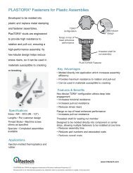
PlastorX® <strong>Fasteners</strong> For Plastic assemblies<br />
Developed to be molded into <strong>plastic</strong><br />
and replace metal stamping and<br />
fastener assemblies, PlasTORX®<br />
studs are engineered to provide high<br />
resistance to rotation and pull-out,<br />
ensuring a high-per<strong>for</strong>mance<br />
assembly. Its hex-lobular design<br />
helps reduce stress risers, so it can<br />
be used in materials susceptible to<br />
cracking or breaking.<br />
sPeciFicaTions<br />
Sizes • M4 – M12 (#8 - 1/2")<br />
Lengths • Per customer design<br />
Thread Styles • Machine screw; others<br />
as specified<br />
Specials • Completed assemblies<br />
available<br />
aPPlicaTions<br />
Injection-molded thermo<strong>plastic</strong>s and<br />
rubber<br />
28<br />
TORX ®<br />
configuration<br />
flange on top of<br />
head enhances<br />
per<strong>for</strong>mance<br />
PlasTORX Fastener<br />
Key advanTages<br />
• Molded directly into application which increases assembly<br />
efficiency<br />
• Provides maximum resistance to rotation and pull-out<br />
• Can be used in materials susceptible to cracking<br />
Hex-lobular TORX ® FeaTures & beneFiTs<br />
configuration allows deep lobe engagement<br />
• Increases torsional resistance<br />
• Increases pull-out resistance<br />
• Reduces stress risers<br />
Flange on top of head enhances per<strong>for</strong>mance<br />
• Increases pull-out resistance<br />
hex-lobular<br />
design<br />
threaded shaft <strong>for</strong><br />
nut assembly<br />
<strong>Threaded</strong> shaft <strong>for</strong> seating nut member<br />
Designed to be molded directly into component or carrier<br />
strips, allowing multiple fasteners to be installed at one time<br />
• Reduces assembly time<br />
• Reduces part numbers and associated costs<br />
• Reduces overall costs
A Ref.<br />
dimensional daTa – meTric sizes<br />
Thread<br />
Size<br />
Thread<br />
Size<br />
A<br />
Ref.<br />
dimensional daTa – inch sizes<br />
A<br />
Ref.<br />
PlastorX® <strong>Fasteners</strong> For Plastic assemblies<br />
B<br />
C<br />
B<br />
±0.13<br />
B<br />
±.005<br />
D Ø of<br />
threaded shaft<br />
Ø E min.<br />
bearing surface<br />
C<br />
±0.25<br />
C<br />
±.010<br />
D<br />
Max.<br />
D<br />
Max.<br />
• Contour may vary between lobes within<br />
specifed dimensions.<br />
• Dimensions shown are <strong>for</strong> low carbon steel<br />
fasteners. For other materials or modified<br />
designs, contact an <strong>Infastech</strong> applications<br />
engineer.<br />
• Per<strong>for</strong>mance is determined by application<br />
material.<br />
E<br />
Min.<br />
Min.<br />
Molded Mat’l<br />
Width<br />
Min. Molded<br />
Mat’l Height<br />
(B + 25%)<br />
#8 .362 .072 .030 .031 .248 .489 .090<br />
#10 .431 .090 .041 .031 .289 .585 .113<br />
1/4 .571 .118 .041 .031 .394 .797 .148<br />
5/16 .645 .145 .049 .039 .445 .909 .181<br />
3/8 .787 .192 .049 .039 .620 1.122 .240<br />
1/2 .929 .271 .055 .039 .728 1.335 .339<br />
E<br />
Min.<br />
Min.<br />
Molded Mat’l<br />
Width<br />
Min. Molded<br />
Mat’l Height<br />
(B + 25%)<br />
M4 9.19 1.84 0.50 0.8 6.30 12.41 2.30<br />
M5 10.95 2.28 0.80 0.8 7.35 14.85 2.85<br />
M6 14.50 3.00 0.80 0.8 10.00 20.25 3.75<br />
M8 16.38 3.68 1.00 1.0 11.30 23.10 4.60<br />
M10 19.99 4.88 1.00 1.0 15.75 28.50 6.10<br />
M12 23.60 6.88 1.14 1.0 18.50 33.90 8.60<br />
Decorah Operations<br />
1-800-544-6117<br />
www.infastech.com<br />
Elco ® , iForm and <strong>Infastech</strong> are trademarks of <strong>Infastech</strong> Intellectual Properties Pte Ltd.<br />
TORX PLUS ® is a registered trademark of Acument Intellectural Properties LLC.<br />
Avdel ® is a registered trademark of Avdel UK Ltd.<br />
Plastite ® is a registered trademark of Research Engineering & Manufacturing Inc.<br />
©2011 <strong>Infastech</strong> Intellectual Properties Pte Ltd. All rights reserved.<br />
29
P e r m a - n u t ® i n s e r t s F o r th i n m a t e r i a l s<br />
Combining the functions of a semi-<br />
tubular rivet and a nut, Perma-Nut®<br />
inserts provide an economical and<br />
permanent threaded fitting with<br />
minimal de<strong>for</strong>mation of the<br />
application. They can be used in<br />
<strong>plastic</strong>s, metals and composite<br />
materials.<br />
sPeciFicaTions<br />
Internal Thread Sizes • M2 to M10 (#4<br />
to 3/8"); special sizes available upon<br />
request<br />
Materials • Low carbon steel, brass,<br />
aluminum<br />
Finish • Zinc plate with chromate<br />
sealer; others as required<br />
Thermoset <strong>plastic</strong>s that require a<br />
threaded fitting. Application testing is<br />
required to determine usability in<br />
thermo<strong>plastic</strong> materials.<br />
30<br />
Key advanTages<br />
• Can per<strong>for</strong>m a variety of functions in thinner materials<br />
• Permits efficient installation<br />
FeaTures & beneFiTs<br />
Perma-Nut Insert<br />
Semi-tubular rivet and nut with roll clinch set<br />
Threads in nut head provide a more secure joint<br />
Underhead serrations grip material<br />
• Increases rotational resistance<br />
• Increases reliability<br />
staking roll<br />
clincher<br />
Roll-clinch installation (requiring two sided access) <strong>for</strong> more<br />
efficient installation<br />
• Automatic or semi-automatic multiple-station equipment,<br />
standard tooling or high-speed riveting can be used<br />
• Allows multiple installation<br />
• Lowers assembly costs<br />
Can be used in materials as thin as 0.254mm (.010") and<br />
where low profiles are required<br />
Highly versatile design to per<strong>for</strong>m a variety of functions to meet<br />
the specific needs of your application<br />
• Nut plate applications to eliminate installing nuts in hard-toreach<br />
areas<br />
• Nut and rivet applications<br />
• Nut, rivet and spacer applications<br />
• Nut and bushing applications<br />
Initial testing is required to determine optimal roll crimp<br />
pressure <strong>for</strong> each application. Please contact an <strong>Infastech</strong><br />
applications engineer <strong>for</strong> technical assistance.<br />
Decorah Operations<br />
1-800-544-6117<br />
www.infastech.com<br />
Elco ® , iForm and <strong>Infastech</strong> are trademarks of <strong>Infastech</strong> Intellectual Properties Pte Ltd. TORX PLUS ® is a registered trademark of Acument<br />
Intellectural Properties LLC. Avdel ® is a registered trademark of Avdel UK Ltd. Plastite ® is a registered trademark of Research Engineering<br />
& Manufacturing Inc.<br />
©2011 <strong>Infastech</strong> Intellectual Properties Pte Ltd. All rights reserved.
S<br />
F E<br />
S<br />
S<br />
F<br />
S<br />
A<br />
C<br />
D<br />
A<br />
C<br />
A<br />
A<br />
Standard Set<br />
Flush Set<br />
B<br />
B<br />
B<br />
counterbore<br />
B<br />
P e r m a - n u t ® i n s e r t s F o r th i n m a t e r i a l s<br />
dimensional daTa, sTandard seT – inch sizes<br />
A<br />
Head<br />
Dia.<br />
B<br />
Head<br />
Ht.<br />
S<br />
Serr.<br />
Ht.<br />
C<br />
Body<br />
Dia.<br />
D<br />
Hole<br />
Dia.<br />
E<br />
Clinch Allowance<br />
F<br />
Body Length<br />
Thread<br />
No. of<br />
Size<br />
Threads<br />
Min. Nom. Max. Min. Max.<br />
4-40UNC-2B .312 .093 .010 3-1⁄2 to 4 .158 .173 .072 .078 .083 .125 .313<br />
5-40UNC-2B .344 .109 .010 4 to 4-1⁄2 .189 .203 .085 .092 .098 .125 .375<br />
6-32UNC-2B .344 .109 .010 3-1⁄2 to 4 .189 .203 .085 .092 .098 .125 .375<br />
8-32UNC-2B .375 .125 .010 3-1⁄2 to 4 .227 .242 .106 .112 .118 .141 .500<br />
10-24UNC-2B .406 .125 .010 3 to 3-1⁄2 .250 .265 .115 .123 .130 .141 .500<br />
10-32UNF-2B .406 .125 .010 3-1⁄2 to 4 .250 .265 .115 .124 .132 .141 .500<br />
1/4-20UNC-2B .469 .174 .010 3 to 3-1⁄2 .328 .343 .156 .164 .172 .156 .625<br />
1/4-28UNF-2B .469 .174 .010 4 to 4-1⁄2 .328 .343 .156 .164 .172 .156 .625<br />
5/16-18UNC-2B .530 .250 .010 3 to 3-1⁄2 .421 .437 .203 .214 .224 .219 .625<br />
5/16-24UNF-2B .530 .250 .010 4 to 4-1⁄2 .421 .437 .203 .214 .224 .219 .625<br />
dimensional daTa, sTandard seT – meTric sizes<br />
Thread<br />
Size<br />
A<br />
Head<br />
Dia.<br />
B<br />
Head<br />
Ht.<br />
S<br />
Serr.<br />
Ht.<br />
No. of<br />
Threads<br />
To establish proper body length <strong>for</strong> a roll clinch, add the total compressed thicknesses of the work pieces to be assembled<br />
to the nom. clinch allowance given in the table <strong>for</strong> each body dia. Additional sizes available upon request.<br />
dimensional daTa, Flush seT – inch sizes<br />
C<br />
Body<br />
Dia.<br />
dimensional daTa, Flush seT – meTric sizes<br />
D<br />
Hole<br />
Dia.<br />
F<br />
Body Length<br />
F<br />
Body Length<br />
Min. Nom. Max Min. Max<br />
M2 X 0.4-6H 7.2 2.2 .254 3-1⁄2 to 4 3.6 4.01 1.67 1.78 1.88 3.2 9.5<br />
M3 x 0.5-6H 8.7 2.8 .254 3-1⁄2 to 4 4.8 5.15 2.20 2.35 2.49 3.2 9.5<br />
M4 x 0.7-6H 9.5 3.4 .254 3 to 3-1⁄2 5.8 6.14 2.64 2.82 2.99 3.6 12.7<br />
M5 x 0.8-6H 10.8 3.5 .254 3 to 3-1⁄2 6.9 7.24 3.15 3.35 3.55 3.6 12.7<br />
M6 x 1.0-6H 11.9 4.4 .254 3 to 3-1⁄2 8.3 8.71 3.83 4.07 4.31 4.0 15.9<br />
M8 x 1.25-6H 13.5 6.1 .254 3 to 3-1⁄2 10.4 10.76 4.77 5.09 5.41 5.5 15.9<br />
M10 x 1.50-6H 16.2 7.5 .254 4 to 4-1⁄2 12.4 12.77 5.69 6.07 6.45 5.5 20.6<br />
A<br />
Head<br />
Dia.<br />
B<br />
Head<br />
Height<br />
S<br />
Serr.<br />
Height<br />
C<br />
Body<br />
Dia.<br />
D<br />
Min<br />
Length<br />
Work Hole<br />
Thread<br />
No. of<br />
Size<br />
Threads<br />
Dia. Drill<br />
4-40UNC-2B .312 .109 .010 3-1⁄2 to 4 .189 .031 .191 #11<br />
5-40UNC-2B .344 .109 .010 3-1⁄2 to 4 .189 .031 .191 #11<br />
6-32UNC-2B .344 .125 .010 3-1⁄2 to 4 .212 .031 .215 #3<br />
8-32UNC-2B .375 .140 .010 3 to 3-1⁄2 .250 .062 .256 F<br />
10-24UNC-2B .406 .177 .010 3 to 3-1⁄2 .281 .062 .287 L<br />
10-32UNF-2B .406 .177 .010 3 to 3-1⁄2 .281 .062 .287 L<br />
1/4-20UNC-2B .469 .208 .010 3 to 3-1⁄2 .375 .062 .380 V<br />
1/4-20UNF-2B .469 .208 .010 3 to 3-1⁄2 .375 .062 .380 V<br />
5/16-18UNC-2B .530 .240 .010 3 to 3-1⁄2 .421 .062 .428 27/64<br />
5/16-24UNF-2B .530 .240 .010 3 to 3-1⁄2 .421 .062 .428 27/64<br />
A<br />
Head<br />
Dia.<br />
B<br />
Head<br />
Height<br />
S<br />
Serr.<br />
Height<br />
C<br />
Body<br />
Dia.<br />
D<br />
Min<br />
Length<br />
Thread<br />
No. of<br />
Work Hole<br />
Size<br />
Threads<br />
Dia. Drill<br />
M2 x 0.4-6H 7.2 2.2 .254 3-1⁄2 to 4 3.6 0.8 3.73 26<br />
M3 x 0.5-6H 8.7 2.8 .254 3-1⁄2 to 4 4.8 0.8 4.91 10<br />
M4 x 0.7-6H 9.5 3.4 .254 3 to 3-1⁄2 5.8 1.6 5.80 1<br />
M5 x 0.8-6H 10.8 3.5 .254 3 to 3-1⁄2 6.9 1.6 7.00 7mm<br />
M6 x 1.0-6H 11.9 4.4 .254 3 to 3-1⁄2 8.3 1.6 8.43 Q<br />
M8 x 1.25-6H 13.5 6.1 .254 3 to 3-1⁄2 10.4 1.6 10.49 Z<br />
M10 x 1.25-6H 16.2 7.5 .254 4 to 4-1⁄2 12.6 1.6 12.70 1/2<br />
31
o t h e r th r e a d e d Fa s t e n e r s F o r P l a s t i c s<br />
narrow<br />
thread<br />
profile<br />
recessed<br />
thread<br />
root<br />
32<br />
tri-roundular<br />
body<br />
optimal<br />
thread<br />
pitch<br />
narrow<br />
thread<br />
profile<br />
5°<br />
larger pitch<br />
length<br />
multiple<br />
flutes<br />
large minor<br />
diameter<br />
unique<br />
thread<br />
profile<br />
asymmetrical<br />
thread profile<br />
PushTiTe ® & PushTiTe ii Thread-Forming FasTeners<br />
The unique thread profile of Pushtite fasteners allows them to<br />
be simply pressed into place, virtually eliminating strip-out<br />
during initial assembly and providing high pull-out strength.<br />
• Tri-roundular shape minimizes stress on the boss<br />
• Screws can be removed and reinserted if necessary, or can be<br />
made tamper-resistant<br />
• Can be gang-driven, which can cut costs<br />
• Allows displaced air to escape during insertion to prevent<br />
pneumatic failure of boss<br />
bF-Plus Thread-cuTTing FasTeners<br />
The unique thread-cutting flutes of the BF-Plus fastener were<br />
designed to provide deep, fully-cut mating threads with minimal<br />
contamination. It helps ensure reliable fastening in harder<br />
<strong>plastic</strong>s.<br />
• Multiple flutes <strong>for</strong> thread cutting extend through first full<br />
thread diameter to reduce radial stress and boss damage<br />
• 5° reverse angle of flutes retains chips to minimize<br />
contamination<br />
• 48° thread profile with extended height, combined with a<br />
longer pitch length, increases flank and shear area to increase<br />
pull-out resistance and strip-out resistance<br />
duro-PT ® Thread-Forming FasTeners<br />
Duro-PT ® thread-<strong>for</strong>ming fasteners are engineered to meet the<br />
unique requirements of rein<strong>for</strong>ced thermo<strong>plastic</strong>s and light<br />
alloys.<br />
• Asymmetrical 30° thread profile reduces radial stress and<br />
minimizes installation torque<br />
• Allows deep thread engagement to increase pull-out strength<br />
and increase resistance to vibration loosening<br />
• Eliminates need <strong>for</strong> supplementary locking devices<br />
• Recessed thread root provides space <strong>for</strong> displaced material,<br />
minimizing risk of clogging and galling during assembly<br />
hi-Wide Thread-Forming FasTeners<br />
• Large minor diameter<br />
• 40°, 45°, or 48° thread profiles available<br />
• Wide thread spacing <strong>for</strong> greater shear area to increase<br />
pull-out resistance<br />
• Thread-<strong>for</strong>ming and thread-cutting styles are available<br />
• Variety of point styles available <strong>for</strong> thread-<strong>for</strong>ming screws
The TORX PLUS ® Drive System is the<br />
ideal drive system <strong>for</strong> screws <strong>for</strong><br />
<strong>plastic</strong>s, since it provides optimum<br />
torque transfer, even when <strong>for</strong>ming or<br />
cutting threads in rein<strong>for</strong>ced <strong>plastic</strong>s.<br />
Its unmatched ability to increase<br />
productivity by outper<strong>for</strong>ming<br />
competing drive systems can lower<br />
assembly costs.<br />
sPeciFicaTions<br />
Drive Sizes • 1IP – 100IP (recess) to fit<br />
screw sizes M0.9 – M24 (#0 – 1")<br />
Styles • Internal, external, low-profile<br />
external, tamper-resistant, TORX PLUS®<br />
Drive/external hex or TORX PLUS Drive/<br />
slotted<br />
Drive Tools • TORX PLUS Drive tools fit<br />
both inch and metric fasteners.<br />
Standard and special tooling is available<br />
from over 3,000 outlets around the<br />
world. For more in<strong>for</strong>mation, please<br />
contact <strong>Infastech</strong>.<br />
t o r X P l u s ® d r i v e s y s t e m<br />
large cross-sectional area<br />
TORX PLUS ® Drive System<br />
elliptically-based gemometry<br />
0° drive angle<br />
broad<br />
contact<br />
surface<br />
Key advanTages<br />
• Allows optimum torque transfer <strong>for</strong> <strong>for</strong>ming or cutting threads<br />
in <strong>plastic</strong> applications<br />
Unique, elliptically-based geometric configuration to maximize<br />
engagement between driver and fastener<br />
True 0° drive angle virtually eliminates the radial <strong>for</strong>ces that<br />
cause stress on fastener recesses with vertical walls<br />
• Allows optimum torque transfer, even in <strong>plastic</strong>s rein<strong>for</strong>ced<br />
with nylon or carbon fibers<br />
Vertical sidewalls completely enclose the driver tip, reducing<br />
tool slippage and virtually eliminating camout<br />
• Prevents damage to the fastener and surrounding surfaces,<br />
which often occurs with cross recess fasteners<br />
• Eliminates the debris camout can create, which can damage<br />
sensitive applications<br />
• Minimizes damage to application<br />
Higher torque removal capability than any other drive system<br />
• Helps minimize damage to boss from removal and reinsertion<br />
of the screw<br />
Improved fit between fastener and tool minimizes wear on the<br />
drive bit<br />
• Drive bit life lengthened as much as 12 times<br />
• Downtime and costs are reduced since significantly fewer<br />
drive bit changes are required<br />
33
g l o s s a r y<br />
BOSS: Protuberance on a <strong>plastic</strong> part designed to add strength<br />
and/or facilitate fastening or alignment.<br />
CREEP: Permanent de<strong>for</strong>mation of a material caused by time,<br />
temperature and pressure.<br />
DRAFT ANGLE: The amount of slope in the boss<br />
hole and/or outside edge, measured from a line<br />
perpendicular to the bottom of the boss.<br />
FILLERS: Additives or rein<strong>for</strong>cements that are<br />
added to a polymer to change one or more of its<br />
characteristics such as strength, wear resistance,<br />
etc.<br />
FLANK ANGLE: See thread profile.<br />
HELIX ANGLE: The angle between the helix of the<br />
thread and a line perpendicular to the axis of<br />
the screw.<br />
LEAD THREAD: The thread length from where<br />
it starts to where it becomes full size. This<br />
distance is usually one-half the fastener<br />
diameter.<br />
LENGTH OF ENGAGEMENT: The length of full-sized fastener<br />
threads that engage in the nut material.<br />
The length of the lead thread is not<br />
counted in the length of engagement,<br />
since its reduced size minimizes any<br />
per<strong>for</strong>mance benefits. The length of<br />
engagement is usually expressed in<br />
relationship to the nominal diameter of the<br />
screw (e.g. 2 to 2-1/2 diameters of<br />
engagement).<br />
MAJOR DIAMETER: The outside or largest<br />
diameter of an external thread.<br />
MINOR DIAMETER: The inside or smallest<br />
diameter of an external thread.<br />
NOMINAL DIAMETER: The major diameter<br />
of a screw or, in tri-round fasteners, the “C”<br />
dimension.<br />
PEAK DRIVE TORQUE: Amount of <strong>for</strong>ce<br />
required to pull the members of a joint together; the point at<br />
which clamp begins to generate.<br />
34<br />
length of<br />
eng.<br />
lead<br />
thread<br />
MØ<br />
mØ<br />
draft angle<br />
helix<br />
helix angle<br />
RADIAL STRESS (hoop stress): Forces<br />
that propagate from the screw towards<br />
the outside diameter of the boss.<br />
SHEAR: Force that tends to divide an<br />
object along a plane parallel to the<br />
opposing stresses.<br />
THERMOPLASTIC: These widely used<br />
polymers are characterized by their<br />
ductility (fillers may be added to<br />
increase stiffness). Thermo<strong>plastic</strong>s can<br />
be remelted and re<strong>for</strong>med several times<br />
without degrading the material.<br />
THERMOSET: These polymers are<br />
characterized by extreme stiffness. The<br />
initial molding process causes a<br />
chemical reaction which “cures” the<br />
material, so the resin cannot be<br />
reprocessed.<br />
THREAD ENGAGEMENT: The amount of<br />
thread tooth that is filled<br />
by the application<br />
material. This<br />
measurement is usually<br />
expressed as a<br />
percentage and is used<br />
to determine optimal<br />
hole size.<br />
THREAD PROFILE: The<br />
angle between the<br />
flank of the thread and<br />
a line perpendicular to<br />
the screw axis.<br />
flank<br />
ULTIMATE TORQUE: The amount of<br />
<strong>for</strong>ce at which a fastener begins to strip<br />
or otherwise fail in a joint.
s u c c e s s w i t h F a s t e n e r s F o r P l a s t i c s<br />
meeTing The needs oF demanding aPPlicaTions<br />
This stereo/heating control panel cover is made from a<br />
particularly brittle <strong>plastic</strong> which is very prone to strip-out. We<br />
recommended a PT ® screw with TORX PLUS ® Drive System to<br />
attach the cover to the dashboard. The PT thread minimizes<br />
strip-out, while the TORX PLUS Drive ensures that the proper<br />
torque level is reached easily, preventing over-clamping. The<br />
customer saved $105 per car in replacement/warranty costs.<br />
reducing cosTs by simPliFying assembly<br />
The original assembly of a pocket pager required threading a<br />
machine screw into a brass insert that was press-fit into the<br />
mating case housing – a costly and inefficient process. This<br />
custom-designed Plastite ® screw with TORX PLUS Drive replaced<br />
the entire insert combination. This made assembly more<br />
efficient and allowed the company to realize substantial cost<br />
savings.<br />
securing a Wide range oF maTerials<br />
A leading manufacturer of automotive HVAC products uses<br />
Powergrip ® fasteners in their blower motor assembly. This<br />
involves fastening four stacked components – one sheet metal,<br />
two <strong>plastic</strong>, and one rubber – to a sheet metal housing. The<br />
Powergrip fastener positions the rubber and <strong>plastic</strong> components<br />
without crushing them, while securing them to the metal. Using<br />
one fastener <strong>for</strong> all materials has helped speed assembly,<br />
resulting in increased productivity.<br />
imProving reliabiliTy Through ProPer design<br />
The manufacturer of these automotive headlamps switched to a<br />
Duro-PT ® thread-cutting screw, which allowed them to eliminate<br />
a supplemental gluing operation and still reduce vibration<br />
loosening problems. The result was a higher quality product and<br />
reduced warranty costs.<br />
35
s u c c e s s w i t h F a s t e n e r s F o r P l a s t i c s<br />
36<br />
imProving PerFormance & reducing cosTs<br />
Made from a thermoset <strong>plastic</strong>, an industrial circuit breaker<br />
originally utilized a threaded insert/machine screw combination.<br />
Engineers knew that replacing this combination with a single<br />
screw would reduce costs, so they tested several different<br />
fasteners in the application. A Duro-PT ® screw with TORX PLUS ®<br />
Drive outper<strong>for</strong>med all of them. The thread design provides the<br />
high resistance to strip-out and vibration loosening they need,<br />
while the TORX PLUS Drive optimizes the torque transfer<br />
required to cut threads in the hard material.<br />
mainTaining inTegriTy oF aPPlicaTions<br />
Normal in-service loads caused boss cracking problems, loose<br />
fasteners and rattle problems in these glove box doors,<br />
resulting in high warranty costs. We were called in to offer an<br />
alternative that would allow the customer to use their existing<br />
design. We developed a PT ® screw that eliminated boss<br />
cracking, offered positive resistance to vibration loosening, and<br />
eliminated rattles in the dashboard from the glove box door.<br />
increasing assembly eFFiciency<br />
A patented design <strong>for</strong> an automotive fluid reservoir and fan<br />
shroud required a fastener that could be included in the blowmolding<br />
process and would maintain the integrity of the<br />
application. This custom-designed PlasTORX ® stud is molded<br />
directly into the unit, eliminating through holes and resulting in<br />
a more cost-efficient assembly. Because of their high resistance<br />
to rotation and pull-out, the PlasTORX studs also increase the<br />
reliability of the application.<br />
eliminaTing Problems on The assembly line<br />
Cracking and boss failure were common problems <strong>for</strong> an audio<br />
components manufacturer who tried to seat sheet metal screws<br />
in <strong>plastic</strong> bosses. Our applications specialists reviewed the<br />
application and determined that a Plastite ® fastener would fit in<br />
the current boss design. The Plastite fastener generates less<br />
radial stress in the application than the sheet metal screw, so<br />
boss damage is minimized, increasing product reliability.
s u c c e s s w i t h F a s t e n e r s F o r P l a s t i c s<br />
Providing assembly soluTions<br />
A Perma-Nut ® insert is used as a nut plate by a truck<br />
manufacturer to secure a circuit board to the vehicle. The<br />
board, which is .060" (1.52mm) thick, is extremely fragile and<br />
subject to failure if placed under stress during installation. This<br />
custom-designed Perma-Nut insert with M2 threads eases<br />
assembly by providing a system where the nuts are already in<br />
place, eliminating the difficulty of assembling loose nuts in a<br />
hard-to-reach area.<br />
increasing ProducT reliabiliTy<br />
The design of this stadium seating, made of polypropylene, was<br />
changed to include brackets with a powder coating. The<br />
Plastite ® fasteners used in the original design could not meet<br />
the new per<strong>for</strong>mance requirements. The manufacturer switched<br />
to PT ® fasteners, which provide the necessary resistance to pullout.<br />
There<strong>for</strong>e, the seats are less likely to be damaged from<br />
vibration and other in-use conditions.<br />
imProving ProducT PerFormance<br />
In order to eliminate rattle problems in a radio/cassette tape<br />
bin, the manufacturer converted to a PT ® screw sized to meet<br />
the existing boss design. The PT screw minimizes clamp load<br />
loss to protect against vibration loosening and ensure a high<br />
load-carrying capability. This in turn increases the product’s<br />
quality and reliability, helping to increase customer satisfaction.<br />
solving mulTiPle assembly Problems<br />
A manufacturer of relay monitoring equipment needed to<br />
assemble banks of PCB modules contained in nylon outer<br />
module chassis, which are installed into sub-racks. Rivscrew ®<br />
was specified to assemble the outer casings as well as the relay<br />
modules. The Rivscrew fasteners provided rapid one-sided<br />
installation, high residual clamp-up, resistance to vibration, and<br />
left a flush surface so that modules could be slotted side by<br />
side with no air gaps. In the case of the relay modules, the<br />
Rivscrew fastener is placed directly into a pre-drilled hole in the<br />
nylon chassis material and <strong>for</strong>ms a radial thread during<br />
placement. This enables good vibration resistance and ensures<br />
no residue is generated.<br />
37
Decorah Operations<br />
304 Kerr Drive • Decorah, IA 52101-2494<br />
1-800-544-6117<br />
www.infastech.com<br />
The in<strong>for</strong>mation in this manual is not to be considered a specification.<br />
Elco ® , iForm and <strong>Infastech</strong> are trademarks of <strong>Infastech</strong> Intellectual Properties Pte Ltd. TORX ® , TORX PLUS ® , PlasTORX ® , Powergrip ® , Pushtite ® , Perma-Nut ®<br />
are trademarks of Acument Intellectural Properties LLC. Rivscrew ® and Avdel ® are registered trademarks of<br />
Avdel UK Ltd. PT ® is a registered trademark of EJOT Verbindungstechnik & Co. KG. Plastite ® is a registered trademark of<br />
Research Engineering & Manufacturing Inc.<br />
©2011 <strong>Infastech</strong> Intellectual Properties Pte Ltd. All rights reserved.