
Create successful ePaper yourself
Turn your PDF publications into a flip-book with our unique Google optimized e-Paper software.
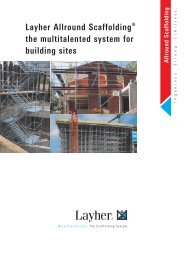
<strong>Layher</strong>®<br />
More Possibilities. The Scaffolding System.<br />
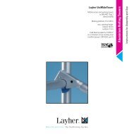
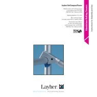
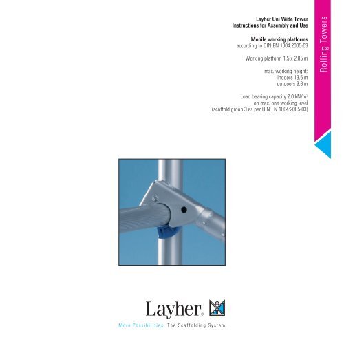
<strong>Layher</strong> <strong>Uni</strong> <strong>Wide</strong> Tower<br />
Instructions for Assembly and Use<br />
Mobile working platforms<br />
according to DIN EN 1004:2005-03<br />
Working platform 1.5 x 2.85 m<br />
max. working height:<br />
indoors 13.6 m<br />
outdoors 9.6 m<br />
Load bearing capacity 2.0 kN/m 2<br />
on max. one working level<br />
(scaffold group 3 as per DIN EN 1004:2005-03)<br />
Rolling Towers
2<br />
Tower Types without ladder access <strong>Layher</strong> <strong>Uni</strong> <strong>Wide</strong> Tower<br />
For outdoor use observe height limits.<br />
Tower Models<br />
2101– 2106<br />
Tower Model 2101 2102 2103 2104 2105 2106<br />
Working height (m) 3.5 4.5 5.5 6.5 7.5 8.5<br />
Scaffold height 1) (m) 2.6 (2.45) 3.6 (3.45) 4.6 (4.45) 5.6 (5.45) 6.6 (6.45) 7.79 (7.64)<br />
Platform height (m) 1.5 2.5 3.5 4.5 5.5 6.6<br />
Weight (kg) [without ballast] 114.2 164.3 178.9 199.9 277.7 379.3<br />
Tower Models<br />
2107– 2111<br />
1.5 2.85<br />
1) Values in brackets: minimum tower height incl. spigots.<br />
Tower Model 2107 2108 2109 2110 2111<br />
Working height (m) 9.6 10.6 11.6 12.6 13.6<br />
Scaffold height 1) (m) 8.79 (8.64) 9.79 (9.64) 10.79 (10.64) 11.79 (11.64) 12.79 (12.64)<br />
Platform height (m) 7.6 8.6 9.6 10.6 11.6<br />
Weight (kg) [without ballast] 408.3 422.1 499.9 513.7 542.7<br />
1) Values in brackets: minimum tower height incl. spigots.
Tower Types with stabilizers, extendable <strong>Layher</strong> <strong>Uni</strong> <strong>Wide</strong> Tower<br />
For outdoor use observe height limits.<br />
Tower Models<br />
2126 – 2128<br />
Tower Model 2126 2127 2128<br />
Working height (m) 8.5 9.5 10.5<br />
Scaffold height 1) (m) 7.7 (7.45) 8.7 (8.45) 9.7 (9.45)<br />
Platform height (m) 6.5 7.5 8.5<br />
Weight (kg) [without ballast] 336.7 365.7 379.5<br />
Tower Models<br />
2129 – 2131<br />
1) Values in brackets: minimum tower height incl. spigots.<br />
Tower Model 2129 2130 2131<br />
Working height (m) 11.5 12.5 13.5<br />
Scaffold height 1) (m) 10.7 (10.45) 11.7 (11.45) 12.7 (12.45)<br />
Platform height (m) 9.5 10.5 11.5<br />
Weight (kg) [without ballast] 457.3 471.1 500.1<br />
1) Values in brackets: minimum tower height incl. spigots.<br />
3
4<br />
Tower Types with stabilizers, 5 m <strong>Layher</strong> <strong>Uni</strong> <strong>Wide</strong> Tower<br />
For outdoor use observe height limits.<br />
Tower Models<br />
2146 – 2148<br />
Tower Model 2146 2147 2148<br />
Working height (m) 8.5 9.5 10.5<br />
Scaffold height 1) (m) 7.7 (7.45) 8.7 (8.45) 9.7 (9.45)<br />
Platform height (m) 6.5 7.5 8.5<br />
Weight (kg) [without ballast] 368.7 397.7 411.5<br />
Tower Models<br />
2249 – 2251<br />
1) Values in brackets: minimum tower height incl. spigots<br />
Tower Model 2149 2150 2151<br />
Working height (m) 11.5 12.5 13.5<br />
Scaffold height 1) (m) 10.7 (10.45) 11.7 (11.45) 12.7 (12.45)<br />
Platform height (m) 9.5 10.5 11.5<br />
Weight (kg) [without ballast] 489.3 503.1 532.1<br />
1) Values in brackets: minimum tower height incl. spigots
Tower Types without ladder access <strong>Layher</strong> <strong>Uni</strong> <strong>Wide</strong> Tower<br />
For outdoor use observe height limits.<br />
Ladder frames with non-continuous central uprights (new production)<br />
and with continuous central uprights (old production) can be used together.<br />
Tower Models<br />
2201– 2206<br />
Tower Model 2201 2202 2203 2204 2205 2206<br />
Working height (m) 3.5 4.5 5.5 6.5 7.5 8.7<br />
Scaffold height 1) (m) 2.70 (2.45) 3.70 (3.45) 4.70 (4.45) 5.70 (5.45) 6.70 (6.45) 7.89 (7.64)<br />
Platform height (m) 1.5 2.5 3.5 4.5 5.5 6.7<br />
Weight (kg) [without ballast] 134.4 190.1 207.9 225.7 306.7 414.30<br />
Tower Models<br />
2207– 2211<br />
1) Values in brackets: minimum tower height incl. spigots<br />
Tower Model 2207 2208 2209 2210 2211<br />
Working height (m) 9.7 10.7 11.7 12.7 13.7<br />
Scaffold height 1) (m) 8.89 (8.64) 9.89 (9.64) 10.89 (10.64) 11.89 (11.64) 12.89 (12.64)<br />
Platform height (m) 7.7 8.7 9.7 10.7 11.7<br />
Weight (kg) [without ballast] 440.1 450.7 531.7 542.3 574.50<br />
1) Values in brackets: minimum tower height incl. spigots<br />
5
Tower Types with ladder access <strong>Layher</strong> <strong>Uni</strong> <strong>Wide</strong> Tower<br />
For outdoor use observe height limits.<br />
Ladder frames with non-continuous central uprights (new production)<br />
and with continuous central uprights (old production) can be used together.<br />
Tower Models<br />
2302– 2306<br />
Tower Model 2302 2303 2304 2305 2306<br />
Working height (m) 4.5 5.5 6.5 7.5 8.7<br />
Scaffold height 1) (m) 3.70 (3.45) 4.70 (4.45) 5.70 (5.45) 6.70 (6.45) 7.89 (7.64)<br />
Platform height (m) 2.5 3.5 4.5 5.5 6.7<br />
Weight (kg) [without ballast] 174.8 194.6 214.5 292.8 426.6<br />
Tower Models<br />
2307– 2311<br />
* 17<br />
15 *<br />
17 *<br />
17 *<br />
15 *<br />
17 *<br />
* 14 * 14<br />
Tower Model 2307 2308 2309 2310 2311<br />
Working height (m) 9.7 10.7 11.7 12.7 13.7<br />
Scaffold height 1) (m) 8.89 (8.64) 9.89 (9.64) 10.89 (10.64) 11.89 (11.64) 12.89 (12.64)<br />
Platform height (m) 7.7 8.7 9.7 10.7 11.7<br />
Weight (kg) [without ballast] 459.3 472.7 551.8 565.2 597.9<br />
6<br />
14 *<br />
1) Values in brackets: minimum tower height incl. spigots. * mount the ladders and ladder supports according to page 22 (components).<br />
1) Values in brackets: minimum tower height incl. spigots. * mount the ladders and ladder supports according to page 22 (components).<br />
16 *<br />
17 *<br />
15 *<br />
14 *<br />
17 *<br />
17 *<br />
17 *<br />
14 *<br />
15 *<br />
17 *<br />
17 *
Assembly <strong>Layher</strong> <strong>Uni</strong> <strong>Wide</strong> Tower<br />
�1 Observe the general instructions for assembly and use on page 32. The examples of assembly shown for tower models 2108 – 2111, 2128 – 2131, 2148 –<br />
2151, 2208 – 2211 and 2308 – 2311 (see pages 2 – 6) are intended for use indoors and enclosed on all sides. In accordance with the regulations as amended<br />
with effect from 1 January 1987, the platform height outdoors is max. 8 m. The material and ballast tables on pages 14 – 16 must be complied with.<br />
�2 Tower Model 2101<br />
without ladders<br />
�3 Assembly of the bottom<br />
working platform<br />
�3.1 Tower Models<br />
2102 – 2105<br />
1<br />
1<br />
5<br />
5<br />
1<br />
8<br />
10<br />
9<br />
1<br />
6<br />
8<br />
7<br />
1<br />
5<br />
5<br />
9<br />
1<br />
28<br />
6<br />
Access side<br />
1<br />
1. With tower 2101, the castors 1 are inserted into<br />
the ladder frames 5 and secured against falling out by<br />
fastening the wing screws on the spindle nuts.<br />
2. Connect the two ladder frames 5 using 2<br />
rolling tower double rear guard rails 8 , in so<br />
doing stiffening them. Then suspend 2 decks 9 in the<br />
4th-from-below rungs of the ladder frames 5.<br />
The snap-on claws of all parts must here be<br />
snapped on from above into the ladder frames 5.<br />
The horizontal clearance between the decks must<br />
not exceed 25 mm.<br />
3. A three-part side protection must be fitted if<br />
required by the regulations applicable for the specific<br />
work being performed.<br />
1. The castors 1 are inserted into the ladder frames 5<br />
and secured against falling out by fastening the wing<br />
screws on the spindle nuts.<br />
2. Bolt an access ledger 28 to the centre of the ladder<br />
frames 5. Suspend rear guard rails 6 and diagonal braces<br />
7 from the bottom rung of the ladder frame. Fit a<br />
deck 9 and an access deck 10 in accordance with the<br />
general drawings (see page 2).<br />
The horizontal clearance between the decks must<br />
not exceed 25 mm.<br />
To lift out the individual parts, open the snap-on<br />
claws by pressing their locking clips. The red<br />
locking clips of the decks permit effortless installation<br />
and removal by a single person; first open<br />
them and place the deck with the opened clips on<br />
the rung, then open the opposite clips and lift out<br />
the deck.<br />
Level the tower using the threaded spindles.<br />
After engagement, push the rear guard rails 6 and<br />
diagonal braces 7 as far outwards as possible.<br />
Level the tower using the threaded spindles.<br />
Further assembly of tower models 2102 to 2105 as<br />
per section 6.<br />
7
Assembly <strong>Layher</strong> <strong>Uni</strong> <strong>Wide</strong> Tower<br />
�3.2 Tower Models<br />
2106 – 2111<br />
2112, 2113<br />
2114, 2115<br />
�4 Tower Model 2201<br />
without ladders<br />
13<br />
5<br />
12<br />
�5 Assembly of the bottom<br />
working platform<br />
�5.1 Tower Models<br />
2202 – 2205<br />
without ladders<br />
8<br />
1<br />
1<br />
5<br />
1<br />
5<br />
10<br />
6<br />
21<br />
6<br />
1<br />
10<br />
1<br />
9<br />
34<br />
9<br />
2<br />
9<br />
9<br />
1<br />
12<br />
7<br />
20<br />
6<br />
20<br />
7<br />
Access side<br />
5<br />
5<br />
10<br />
1<br />
21<br />
6<br />
Access side<br />
1<br />
5<br />
13<br />
2<br />
1<br />
1. The castors 1 are inserted into the mobile beam 2<br />
and secured against falling out by fastening the wing<br />
screws on the spindle nuts.<br />
2. Then clamp the base strut 20 to the leg of the<br />
mobile beam support 2 and suspend a rear guard rail<br />
6 from the mobile beam support. Fit ladder<br />
frames 5 onto the mobile beams 2 and secure them<br />
with spring clips 11.<br />
1. With tower 2201, the castors 1 are inserted into<br />
the ladder frames 5 and secured against falling out by<br />
fastening the wing screws on the spindle nuts.<br />
2. Connect the two ladder frames 5 using 2 beams,<br />
2.85 m 34 , in so doing stiffening them. Then suspend<br />
2 decks 9 in the 4th-from-below rungs of the ladder<br />
frames 5.<br />
The snap-on claws of all parts must here be snapped on<br />
from above into the ladder frames 5. The horizontal clearance<br />
between the decks must not exceed 25 mm.<br />
3. Installation of toe boards: First position the toe<br />
boards 2.85 m 12 inside the ladder frames 5 and stabilize<br />
them by inserting the end toe boards,<br />
1.44 m 13.<br />
1. The castors 1 are inserted into the ladder frames 5<br />
and secured against falling out by fastening the wing<br />
screws on the spindle nuts.<br />
2. The deck supports 21 are bolted centrally to the<br />
ladder frames 5, deck 9 and diagonal braces 7 are<br />
suspended. Ensure that the deck 9 is installed underneath<br />
the access deck 10. Then the base strut 20 is<br />
clamped on the deck support 21.<br />
Fit a deck 9 and an access deck 10 in accordance<br />
with the general drawings (see page 3). The horizontal<br />
clearance between the decks must not exceed 25<br />
mm.<br />
3. Fit diagonal braces 7, deck 9 and access deck 10<br />
or rear guard rails 6 in accordance with the general<br />
drawings (see page 2 + 3). The horizontal clearance<br />
between the decks must not exceed 25 mm. After<br />
installation, push the rear guard rails 6 and<br />
diagonal braces 7 as far outwards as possible<br />
(see assembly drawings, page 2).<br />
To lift out the individual parts, open the snap-on<br />
claws by pressing their locking clips. The red locking<br />
clips of the decks permit effortless installation and<br />
removal by a single person; first open them and<br />
place the deck with the opened clips on the rung,<br />
then open the opposite clips and lift out the deck.<br />
Level the tower using the threaded spindles.<br />
After engagement, push the rear guard rails 6 and<br />
diagonal braces 7 as far outwards as possible.<br />
Level the tower using the threaded spindles.<br />
Further assembly of tower models 2202 to 2205 as<br />
per section 6.
Assembly <strong>Layher</strong> <strong>Uni</strong> <strong>Wide</strong> Tower<br />
5<br />
�5.2 Tower Models<br />
1. The castors 1 are inserted into the ladder frames 5 of the ladder frame 5 and fastened using the clamp<br />
2302 – 2305<br />
and secured against falling out by fastening the wing coupler between the 2nd and 3rd suspension ladder<br />
with ladders<br />
screws on the spindle nuts.<br />
rungs.<br />
5 10<br />
9 14<br />
19<br />
2. The diagonal braces 7 are snapped into the ladder<br />
frames 5 and the adjustable plan brace 4 is<br />
suspended. Suspend the rear guard rail 6 from the<br />
After engagement, push the rear guard rails 6 and<br />
diagonal braces 7 as far outwards as possible.<br />
4<br />
6<br />
ladder frames 5. Fit a deck 9 and an access deck 10 in Level the tower using the threaded spindles.<br />
7<br />
1<br />
accordance with the general drawings (see page 4).<br />
The horizontal clearance between the decks must not<br />
exceed 25 mm. Then fit a ladder with<br />
suspension hooks 14 , 16 or 17 with the appropriate<br />
Further assembly of tower models 2302 to 2305 as<br />
per section 6.<br />
1<br />
double ladder support 18 or 19 (see page 22,<br />
Components and page 4, General drawings).<br />
1<br />
The double ladder support 18 or 19 (see page 22,<br />
Components) is suspended from the bottom rung<br />
�5.3 Tower Models without ladders<br />
2206 – 2211<br />
2212, 2213<br />
2214, 2215<br />
6<br />
�3<br />
11<br />
Wedge<br />
after fitting<br />
�2<br />
5<br />
1<br />
10<br />
11<br />
9<br />
2<br />
9<br />
3<br />
1<br />
6<br />
20<br />
7<br />
Access side<br />
5<br />
11<br />
2<br />
1<br />
Tower Models with ladders<br />
2306 – 2311<br />
2312, 2313<br />
2314, 2315<br />
6<br />
11<br />
1<br />
5<br />
9<br />
11<br />
10<br />
2<br />
9<br />
3<br />
6<br />
7<br />
1<br />
20<br />
14<br />
Access side<br />
5<br />
11<br />
2<br />
1<br />
1. The castors 1 are inserted into the mobile beam 2<br />
and secured against falling out by fastening the wing<br />
screws on the spindle nuts.<br />
2. Fit the basic tube 3 at the mobile beam end 2 and<br />
wedge it tight after aligning it. Then clamp the base<br />
strut 20 to the leg of the mobile beam support 2 and<br />
suspend a deck 9 from the mobile beam support 2. Fit<br />
ladder frames 5 onto the mobile beams and secure<br />
them with spring clips 11.<br />
3. Fit diagonal braces 7, deck 9 and access deck 10<br />
or rear guard rails 6 in accordance with the general<br />
drawings (see page 2 + 4). Ensure that the deck 9 is<br />
underneath the access deck 10.<br />
The horizontal clearance between the decks must not<br />
exceed 25 mm. After installation, push the rear guard<br />
rails 6 and diagonal braces 7 as far outwards as possible<br />
(see assembly drawings, pages 2 + 4).<br />
4. Only for tower models with ladders.<br />
Suspend the ladders 14 , 17 in ladder frame 5<br />
(see also assembly drawing on page 4).<br />
The tower models 2212, 2213, 2214, 2215, 2312, 2313,<br />
2314 and 2315 are equipped with adjustable mobile<br />
beams 2 for use outdoors. Level the tower using the<br />
threaded spindles.<br />
For further assembly see section 6.<br />
9
10<br />
Assembly <strong>Layher</strong> <strong>Uni</strong> <strong>Wide</strong> Tower<br />
�6 Assembly of the intermediate platforms<br />
Tower Models without ladders<br />
2102 – 2111<br />
2112, 2113<br />
2114, 2115 �5a<br />
2202 – 2211<br />
2212, 2213<br />
2214, 2215<br />
�11<br />
�5<br />
Tower Models with ladders<br />
2302 – 2311<br />
2312, 2313<br />
2314, 2315<br />
�11<br />
�9<br />
�7 Assembly of the top working platform<br />
�7.1<br />
11<br />
Tower Models<br />
2102 – 2111<br />
2112, 2113<br />
2114, 2115 5a<br />
2202 – 2211<br />
2212, 2213 11<br />
2214, 2215<br />
13<br />
�5a<br />
5<br />
11<br />
6<br />
5<br />
9<br />
9<br />
6<br />
10<br />
6<br />
6<br />
6<br />
7<br />
10<br />
7<br />
6<br />
10<br />
6<br />
7<br />
15 16<br />
12<br />
5a<br />
5<br />
5a<br />
5<br />
5a<br />
5<br />
11<br />
During assembly and dismantling, system decks or<br />
scaffolding planks to DIN 4420 (minimum dimensions:<br />
28 x 4.5 x 350 cm long) must be installed as<br />
auxiliary decks at maximum height intervals of 2.0<br />
m. These auxiliary decks, providing a safe footing for<br />
assembly and dismantling, must be removed again<br />
after assembly. Each platform must be completely<br />
decked.<br />
1. Assembly is continued by fitting ladder frames 5<br />
and stiffening using 2 diagonal braces 7 and rear<br />
guard rails 6 in accordance with the general drawings<br />
(see pages 3 – 4). Secure the joints of the ladder<br />
frames 5 using spring clips 11.<br />
2. Install intermediate platforms, each comprising 1<br />
deck 9 and 1 access deck 10 at height intervals of<br />
max. 4 m. If these platforms are only used as<br />
intermediate platforms for ascent, it is sufficient to<br />
install 2 rear guard rails 6 for each side as a side<br />
protection. In the case of use as a working platform,<br />
install 2 rear guard rails per side plus toe boards (see<br />
Section 7). The top working level or another working<br />
level must not be used in this case.<br />
The toe boards there must be removed.<br />
Tower Models<br />
with ladders<br />
2302 – 2311<br />
2312, 2313 5a<br />
2314, 2315<br />
11<br />
13<br />
5<br />
6<br />
9<br />
12<br />
7<br />
10<br />
15 17<br />
5a<br />
5<br />
After installation, push the rear guard rails 6 and diagonal<br />
braces 7 as far outwards as possible.<br />
The horizontal clearance between the decks must<br />
not exceed 25 mm.<br />
3. When assembling the tower, ensure without fail<br />
that the diagonal braces 7, decks 9, 10 and rear<br />
guard rails 6 are installed in the correct arrangement<br />
(see general drawings, pages 3 – 4).<br />
The next-up ladder frames 5 must not be fitted here<br />
until the ladder frames 5 underneath them have been<br />
stiffened accordingly.<br />
4. In the case of tower models 2305 – 2311 with<br />
ladders, snap in suspension ladders 15, 17. During<br />
assembly, snap in the suspension ladders 15 or<br />
17 after installing deck 9 and access deck 10 (see<br />
general drawing, page 4). The horizontal clearance<br />
between the decks must not exceed 25 mm.<br />
5. During dismantling, do not remove the appropriate<br />
diagonal braces 7 and stiffening elements 6, 7 until the<br />
ladder frames 5 above them have been<br />
dismantled.<br />
For further assembly see section 7.<br />
After fitting the top ladder frames 5 or 5a and<br />
securing them with spring clips 11 (always fit spring<br />
clips at deck level from the inside towards the outside,<br />
see detail), suspend an access deck 10 and a<br />
deck 9 into the 5th rung from the top. The regulation<br />
side<br />
protection to match the tower model is made by<br />
installing 4 rear guard rails 6 (see pages 3 + 4).<br />
Position the 2 toe boards 2.85 m 12 between the<br />
ladder frames 5 and secure them by inserting end toe<br />
boards, 1.44 m 13.<br />
In the assembly form using inclined ladders 14 to 17<br />
, suspend them in accordance with the general drawings<br />
(see page 4).<br />
After engagement, push the diagonal braces 7<br />
and the rear guard rails 6, 8 and as far outwards as<br />
possible! The horizontal clearance between the decks<br />
must not exceed 25 mm.
Assembly <strong>Layher</strong> <strong>Uni</strong> <strong>Wide</strong> Tower<br />
�7.2 Tower Models<br />
2102 – 2111<br />
2112, 2113<br />
2114, 2115<br />
13<br />
11<br />
5<br />
11<br />
34<br />
�8 Adjusting the mobile beams<br />
1<br />
2<br />
13<br />
11<br />
�7.3 Tower Models<br />
with ladders<br />
2302 – 2311<br />
2312, 2313<br />
2314, 2315<br />
5<br />
11<br />
8<br />
10<br />
6<br />
10<br />
6<br />
5<br />
K M S<br />
V<br />
9<br />
9<br />
12<br />
15 17<br />
12<br />
5<br />
5<br />
11<br />
11<br />
Tower Models<br />
2202 – 2211<br />
2212, 2213<br />
2214, 2215<br />
13<br />
11<br />
13<br />
11<br />
5<br />
Tower Models<br />
with ladders<br />
2302 – 2311<br />
2312, 2313<br />
2314, 2315<br />
5<br />
11<br />
11<br />
34<br />
8<br />
10<br />
6<br />
10<br />
6<br />
The adjustable mobile beam 2 permits working up<br />
against the wall. It can be slid in and out in the<br />
assembled state. It must always be ensured before<br />
adjustment that the ballast weights specified in the<br />
ballast table are fitted in the right places (see page 16).<br />
For adjustment in the assembled state, lower the middle<br />
support (M) attached to the mobile beam 2 as far as<br />
possible and then secure it. The load is taken off the<br />
castors at the sliding parts by turning the spindle (S)<br />
until the adjustment part (V) can be adjusted following<br />
release of the clamping wedge (K).<br />
9<br />
9<br />
12<br />
15 17<br />
12<br />
5<br />
5<br />
11<br />
11<br />
After fitting the top ladder frames 5 or 5a and<br />
securing them with spring clips 11, suspend an<br />
access deck 10 and a deck 9 into the 5th rung from<br />
the top. The regulation side protection to match the<br />
tower model is made by installing 2 double rear guard<br />
rails 8 or 2 beams, 2.85 m 34 (see pages 2 – 4). Position<br />
the 2 toe boards 2.85 m 12 between the<br />
ladder frames 5 and secure them by inserting end toe<br />
boards, 1.44 m 13.<br />
In the assembly form using inclined ladders 14 to<br />
17, suspend them in accordance with the general<br />
drawings (see page 4).<br />
After engagement, push the diagonal braces 7 and<br />
the rear guard rails 6 , 8 and as far outwards as<br />
possible! The horizontal clearance between the decks<br />
must not exceed 25 mm.<br />
After adjustment, fix the clamping wedge (K), put load<br />
back on the castor by turning the spindle, raise the<br />
middle support (M) and secure it.<br />
11
12<br />
Assembly <strong>Layher</strong> <strong>Uni</strong> <strong>Wide</strong> Tower<br />
�9 Operating the castors<br />
1<br />
Fix wing<br />
screw<br />
�10 Maximum spindle adjustment of the various models<br />
max.<br />
40 cm<br />
max.<br />
60 cm<br />
During assembly and while working, the castors 1<br />
must be kept locked by pressing down the brake lever<br />
labelled STOP. When the brake is locked, the lever<br />
labelled STOP is in the down position.<br />
For movement, the castors 1 are unlocked by pushing<br />
the other lever down.<br />
Construction directly on castors with access ledger Construction directly on castors<br />
max. 15 cm<br />
Models: 2102 – 2105<br />
2126 – 2131<br />
2146 – 2151<br />
Assembly with 1323.320<br />
max. 15 cm<br />
Models: 2106 – 2111<br />
Models: 2202 – 2205<br />
max.<br />
40 cm<br />
max. 30 cm<br />
0 cm<br />
Models: 2101; 2201<br />
max. 60 cm<br />
max.<br />
40 cm<br />
max. 30 cm<br />
Models: 2206 – 2211<br />
2306 – 2311
Wall support <strong>Layher</strong> <strong>Uni</strong> <strong>Wide</strong> Tower<br />
Wall support under load<br />
Dismantling<br />
For work performed on a load-bearing wall, ballasting<br />
can be reduced in accordance with the ballast table<br />
(see page 16).<br />
In this case, wall supports must be installed on both<br />
sides of the tower. To do so, the <strong>Uni</strong> distance tube<br />
23 must be used and fastened with couplers 24 to<br />
Top view Top view, with mobile beam Side view<br />
24<br />
23<br />
24<br />
Rolling tower decks 9 10<br />
24<br />
23<br />
24<br />
24<br />
23<br />
24<br />
23<br />
24<br />
24<br />
5 2<br />
Rolling tower decks 9 10<br />
5a<br />
2<br />
During assembly and dismantling, system decks or scaffolding planks to DIN 4420 (minimum dimensions:<br />
28 x 4.5 x 350 cm long) must be installed as auxiliary decks at maximum height intervals of 2.0 m. These<br />
auxiliary decks, providing a safe footing for assembly and dismantling, must be removed again after<br />
assembly. Each platform must be completely decked.<br />
Dismantling is in the reverse order to that of the<br />
assembly steps.<br />
When dismantling, do not remove the bracing elements<br />
such as diagonal braces 2, rear guard rails<br />
6 or access decks 10 until the ladder frames 5, 5a<br />
above them have been dismantled.<br />
the ladder frame 5 , 5a. The mobile beams must be<br />
installed so that they project from the side facing<br />
away from the wall. The wall supports must be<br />
attached at the height of the top working platform<br />
or at most 1 m below that.<br />
24<br />
23<br />
5 5a<br />
24<br />
To lift out the individual parts, open the snap-on claws<br />
by pressing their locking clips. The red locking clips of<br />
the decks permit effortless installation and removal<br />
by a single person; first open them and place the deck<br />
with the opened clips on the rung, then open the<br />
opposite clips and lift out the deck.<br />
13
14<br />
Parts list <strong>Layher</strong> <strong>Uni</strong> <strong>Wide</strong> Tower<br />
The towers 2112, 2113, 2114, 2115, 2212, 2213, 2214 and 2215 are intended for outdoor assembly. The tower base is assembled here in accordance with Section 3.3.<br />
�1 Tabelle 1<br />
�1 Table 1<br />
Tower Model Article No. 2101 2102 2112 2103 2113 2104 2114 2105 2115 2106 2107 2108 2109 2110 2111<br />
Ladder frame 150/4 1299.004 – 2 2 – – 2 2 – – 2 – 2 – 2 –<br />
Ladder frame 150/8 1299.008 2 2 2 4 4 4 4 6 6 6 8 8 10 10 12<br />
Deck 2.85 m 1241.285 2 1 1 1 1 1 1 2 2 2 2 2 3 3 3<br />
Access deck 2.85 m 1242.285 – 1 1 1 1 1 1 2 2 2 2 2 3 3 3<br />
Double rear guard rail 2.85 m 1206.285 2 – – 2 2 – – 2 2 – 2 – 2 – 2<br />
Rear guard rail 2.85 m 1205.285 – 6 6 2 2 6 6 8 8 9 9 11 13 15 15<br />
Diagonal brace 3.35 m 1208.285 – 2 2 2 2 4 4 4 4 6 6 8 8 10 10<br />
Mobile beam, adjustable, 1323.320 – – 2 – 2 – 2 – 2 2 2 2 2 2 2<br />
with deck support<br />
Base strut 2.85 m 1324.285 – – 1 – 1 – 1 – 1 1 1 1 1 1 1<br />
Access ledger 1344.003 – 1 – 1 – 1 – 1 – – – – – – –<br />
Toe board 2.85 m, with claw 1239.285 – 2 2 2 2 2 2 2 2 2 2 2 2 2 2<br />
End toe board 1.44 m 1238.144 – 2 2 2 2 2 2 2 2 2 2 2 2 2 2<br />
Spring clip 1250.000 – 4 4 4 4 8 8 8 8 16 16 20 20 24 24<br />
Castor 200 with spindle, 7 kN 1259.200 4 4 4 4 4 4 4 4 4 4 4 4 4 4 4<br />
Ballast 1249.000 For the number of ballasting weights see the ballast table, page 16<br />
Tower Model Article No. 2201 2202 2212 2203 2213 2204 2214 2205 2215 2206 2207 2208 2209 2210 2211<br />
Ladder frame 150/4 1299.004 – 2 2 – – 2 2 – – 2 – 2 – 2 –<br />
Ladder frame 150/8 1299.008 2 2 2 4 4 4 4 6 6 6 8 8 10 10 12<br />
Deck 2.85 m 1241.285 2 2 2 2 2 2 2 3 3 3 3 3 4 4 4<br />
Access deck 2.85 m 1242.285 – 1 1 1 1 1 1 2 2 2 2 2 3 3 3<br />
Beam 2.85 m 1207.285 2 – – 2 2 – – 2 2 – 2 – 2 – 2<br />
Rear guard rail 2.85 m 1205.285 – 4 4 – – 4 4 6 6 8 8 10 12 14 14<br />
Diagonal brace 3.35 m 1208.285 – 2 2 2 2 4 4 4 4 6 6 8 8 10 10<br />
Deck support, bolt-on, 0.9 m 1326.090 – 2 – 2 – 2 – 2 – – – – – – –<br />
Mobile beam, adjustable, 1323.320 – – 2 – 2 – 2 – 2 2 2 2 2 2 2<br />
with deck support<br />
Base strut 2.85 m 1324.285 – 1 1 1 1 1 1 1 1 1 1 1 1 1 1<br />
Basic tube 2.85 m 1211.285 – – 1 – 1 – 1 – 1 1 1 1 1 1 1<br />
Toe board 2.85 m, with claw 1239.285 2 2 2 2 2 2 2 2 2 2 2 2 2 2 2<br />
End toe board 1.44 m 1238.144 2 2 2 2 2 2 2 2 2 2 2 2 2 2 2<br />
Spring clip 1250.000 – 4 4 4 4 8 8 8 8 16 16 20 20 24 24<br />
Castor 200 with spindle, 7 kN 1259.200 4 4 4 4 4 4 4 4 4 4 4 4 4 4 4<br />
Ballast 1249.000 For the number of ballasting weights see the ballast table, page 16<br />
Additional requirement for special structure with bracket deck surface 1 bracket deck surface 2 bracket deck surfaces<br />
Aluminium console bracket 0.75 m 1341.075 2 4<br />
Deck 2.85 m 1241.285 1 2<br />
Ladder frame 75/4 1297.004 2 4<br />
End toe board 1238.075 2 4<br />
Intermediate deck 2.85 m 1339.285 1 2<br />
Spring clip 1250.000 4 8
Parts list <strong>Layher</strong> <strong>Uni</strong> <strong>Wide</strong> Tower<br />
Construction variants with stabilizers, extendable: 2126 – 2151; with stabilizer, 5 m: 2146 – 2131<br />
Tower Model Article No. 2126 2127 2128 2129 2130 2131<br />
2146 2147 2148 2149 2150 2151<br />
Ladder frame 150/4 1299.004 2 2 – – 2 2 – – 2 2 – –<br />
Ladder frame 150/8 1299.008 6 6 8 8 8 8 10 10 10 10 12 12<br />
Deck 2.85 m 1241.285 2 2 2 2 2 2 3 3 3 3 3 3<br />
Access deck 2.85 m 1242.285 2 2 2 2 2 2 3 3 3 3 3 3<br />
Double rear guard rail 2.85 m 1206.285 – – 2 2 – – 2 2 – – 2 2<br />
Rear guard rail 2.85 m 1205.285 10 10 10 10 12 12 14 14 16 16 16 16<br />
Diagonal brace 3.35 m 1208.285 6 6 6 6 8 8 8 8 10 10 10 10<br />
Stabilizer, extendable 1248.260 4 – 4 – 4 – 4 – 4 – 4 –<br />
Stabilizer 5m 1248.500 – 4 – 4 – 4 – 4 – 4 – 4<br />
Rotation preventer 1248.261 4 4 4 4 4 4 4 4 4 4 4 4<br />
Access ledger 1344.003 1 1 1 1 1 1 1 1 1 1 1 1<br />
Toe board 2.85 m, with claw 1239.285 2 2 2 2 2 2 2 2 2 2 2 2<br />
End toe board 1.44 m 1238.144 2 2 2 2 2 2 2 2 2 2 2 2<br />
Spring clip 1250.000 12 12 12 12 16 16 16 16 20 20 20 20<br />
Castor 200 with spindle, 7 kN 1259.200 4 4 4 4 4 4 4 4 4 4 4 4<br />
Ballast 1249.000 For the number of ballasting weights see the ballast table, page 16<br />
�2 Table 2<br />
Additional requirement compared to Table 1 (2101 – 2111)<br />
Tower Model with ladders Article No. 2302 2312 2303 2313 2304 2314 2305 2315 2306 2307 2308 2309 2310 2311<br />
Suspended ladder 9 rungs 1314.009 1 1 – – – – 1 1 1 – – 1 1 –<br />
Suspended ladder 12 rungs 1314.012 – – – – – – 1 1 – 1 – 1 – 1<br />
Suspended ladder 13 rungs 1314.013 – – 1 1 – – – – – – – – – –<br />
Suspended ladder 16 rungs 1314.016 – – – – 1 1 – – 1 1 2 1 2 2<br />
Double ladder support 0.86 m 1317.086 1 – – – – – 1 – – – – – – –<br />
Double ladder support 1.34 m 1317.134 – – 1 – 1 – – – – – – – – –<br />
Basic tube 1211.285 – 1 – 1 – 1 – 1 1 1 1 1 1 1<br />
Deck 1241.285 – 1 – 1 – 1 – 1 1 1 1 1 1 1<br />
Plan brace, adjustable 1318.000 1 – 1 – 1 – 1 – – – – – – –<br />
Reduced requirement<br />
Rear guard rail 1205.285 1 1 1 1 1 1 1 1 1 1 1 1 1 1<br />
Access ledger 1344.003 1 – 1 – 1 – 1 1 – – – – – –<br />
Additional requirement for special structure with bracket deck surface 1 bracket deck surface 2 bracket deck surfaces<br />
Aluminium console bracket 0.75 m 1341.075 2 4<br />
Deck 2.85 m 1241.285 1 2<br />
Ladder frame 75/4 1297.004 2 4<br />
End toe board 1238.075 2 4<br />
Intermediate deck 2.85 m 1339.285 1 2<br />
Spring clip 1250.000 4 8<br />
The tower models, which can be extended with bracket deck surfaces are shown on page 16 (Ballasting). When operating with brackets, the tower may be loaded with 1.5 kN/m2 (scaffolding<br />
group 2) at one working level only. A maximum of 2 bracket deck surfaces may be assembled. When bracket deck surfaces are fitted, the spindles mustn‘t be extended. The corresponding working<br />
level must be equipped with complete side protection.<br />
15
16<br />
Ballasting <strong>Layher</strong> <strong>Uni</strong> <strong>Wide</strong> Tower<br />
For ballasting, use <strong>Layher</strong> ballast weights 22 , Art. No. 1249.000 (10 kg each). A coupler with hand wheel permits simple, quick and secure fixing of the ballast required at the correct<br />
places. Do not use any liquid or granular ballast materials.<br />
The ballast weights must be distributed evenly to all ballasting fixing points.<br />
Tower Model 2101 2102 2112 2103 2113 2104 2114 2105 2115 2106 2107 2108 2109 2110 2111<br />
2201 2202 2212 2203 2213 2204 2214 2205 2215 2206 2207 2208 2209 2210 2211<br />
2301 2302 2312 2303 2313 2304 2314 2305 2315 2306 2307 2308 2309 2310 2311<br />
Assembly l r Sum l r Sum L R Sum l r Sum L R Sum l r Sum L R Sum l r Sum L R Sum L R Sum L R Sum L R Sum L R Sum L R Sum L R Sum<br />
�indoors in centre position 0 0 � 0 0 � 0 0 � 2 2 4 0 0 � 4 4 8 0 0 � 4 4 8 0 0 � 0 0 � 0 0 � 0 0 � 0 0 � 0 0 � 0 0 �<br />
in off-centre position � � ��� � � 0 0 � � � � 0 0 � � � � 0 0 � � � � 0 0 � 0 0 � 0 0 � 0 0 � 0 0 � 0 2 2 0 2 2<br />
Assembly in centre position 0 0 � 3 3 6 0 0 � 6 6 12 0 0 � 11 11 22 0 0 � 16 16 32 0 0 � 1 1 2 5 5 10 � � � � � � � � � � � �<br />
outdoors in off-centre position � � � � � � 0 0 � � � � 0 0 � � � � 0 0 � � � � 0 4 4 0 6 6 4 14 18 � � � � � � � � � � � �<br />
off-centre with wall support � � � � � � 0 0 � � � � 0 0 � � � � 0 0 � � � � 0 0 � 2 0 2 8 2 10 � � � � � � � � � � � �<br />
Special assembly with brackets<br />
l r Sum l r Sum L R Sum l r Sum L R Sum l r Sum L R Sum l r Sum L R Sum L R Sum L R Sum L R Sum L R Sum L R Sum L R Sum<br />
Assembly in centre pos. (1 bracket)* � � � 0 8 8 0 0 � 0 12 12 0 0 � 0 14 14 0 0 � 0 14 14 0 0 � 0 0 � 0 0 � 0 0 � 0 0 � 0 0 � 0 0 �<br />
�indoors l r Sum l r Sum L R Sum l r Sum L R Sum l r Sum L R Sum l r Sum L R Sum L R Sum L R Sum L R Sum L R Sum L R Sum L R Sum<br />
in centre pos. (2 bracket)* � � � 3 3 6 0 0 � 6 6 12 0 0 � 8 8 16 0 0 � 7 7 14 0 0 � 0 0 � 0 0 � 0 0 ��� � ��� � ��� � �<br />
l r Sum l r Sum L R Sum l r Sum L R Sum l r Sum L R Sum l r Sum L R Sum L R Sum L R Sum L R Sum L R Sum L R Sum L R Sum<br />
Assembly in centre pos. (1 bracket)* � � � 0 16 16 0 0 � 2 22 24 0 0 � 6 26 32 0 0 � 12 30 42 0 0 � 0 6 6�� � ��� � ��� � ��� � ��� � �<br />
outdoors l r Sum l r Sum L R Sum l r Sum L R Sum l r Sum L R Sum l r Sum L R Sum L R Sum L R Sum L R Sum L R Sum L R Sum L R Sum<br />
in centre pos. (2 bracket)* � � � 10 10 20 0 0 � � � � 0 0 � � � ��� � ��� � ��� � ��� � ��� � ��� � ��� � ��� � ��� � �<br />
* In the case of configurations with the adjustable<br />
mobile beam 2 , the latter must be fully extended.<br />
The figures shown indicate the number of ballast<br />
weights of 10 kg each.<br />
Construction variants with stabilizers, extendable<br />
Tower Model 2126 2127 2128 2129 2130 2131<br />
l r Sum l r Sum l r Sum l r Sum l r Sum l r Sum<br />
Assembly indoors in centre position 0 0 � 0 0 � 0 0 � 0 0 � 0 0 � 0 0 �<br />
in off-centre position 0 4 4 0 4 4 0 6 6 0 6 6 0 8 8 0 8 8<br />
off-centre with wall support 0 0 � 0 0 � 0 0 � 0 0 � 0 0 � 0 0 �<br />
Assembly outdoors in centre position 1 1 2 4 4 8 �� �� �� �� �� �� �� �� �� �� �� �<br />
in off-centre position 0 12 12 0 18 18 �� �� �� �� �� �� �� �� �� �� �� �<br />
off-centre with wall support 0 6 6 0 12 12 �� �� �� �� �� �� �� �� �� �� �� �<br />
Construction variants with stabilizers, 5 m<br />
Tower Model 2146 2147 2148 2149 2150 2151<br />
L R Sum L R Sum L R Sum L R Sum L R Sum L R Sum<br />
Assembly indoors in centre position 0 0 � 0 0 � 0 0 � 0 0 � 0 0 � 0 0 �<br />
in off-centre position 0 2 2 0 2 2 0 4 4 0 4 4 0 4 4 0 6 6<br />
off-centre with wall support 0 0 � 0 0 � 0 0 � 0 0 � 0 0 � 0 0 �<br />
Assembly outdoors in centre position 0 0 � �� �� � �� �� �� �� �� �� �� �� �� �� �� �<br />
in off-centre position 0 10 10 0 14 14 �� �� �� �� �� �� �� �� �� �� �� �<br />
off-centre with wall support 0 0 � 0 0 � �� �� �� �� �� �� �� �� �� �� �� �<br />
The figures shown indicate the number of ballast<br />
weights of 10 kg each.<br />
� = no ballast required = example on page 20<br />
� = not permissible<br />
� = no ballast required<br />
� = not permissible
Ballasting <strong>Layher</strong> <strong>Uni</strong> <strong>Wide</strong> Tower<br />
� Attachment of ballast weights<br />
Centre position:<br />
Models: 2101 – 2105<br />
2201 – 2205<br />
l r<br />
l r<br />
l r<br />
Models: 2106 – 2111<br />
2112 – 2115<br />
L l r R<br />
L<br />
l r<br />
l r<br />
L R<br />
R<br />
Models:<br />
2126 – 2131<br />
2146 – 2151<br />
L R<br />
l r<br />
l r<br />
L R<br />
l r<br />
L R<br />
17
Ballasting <strong>Layher</strong> <strong>Uni</strong> <strong>Wide</strong> Tower<br />
� Attachment of ballast weights<br />
Off-centre position:<br />
Models: 2106 – 2111<br />
2112 – 2115<br />
L l r R<br />
L l r R<br />
18<br />
Models: 2126 – 2131<br />
2146 – 2151<br />
l r<br />
l r<br />
L R l r<br />
l r<br />
L<br />
L<br />
R<br />
R<br />
R
Ballasting <strong>Layher</strong> <strong>Uni</strong> <strong>Wide</strong> Tower<br />
� Attachment of ballast weights<br />
Assembly with brackets directly on castors: Assembly with 2 brackets directly on castors: Assembly on mobile beam with 1 bracket:<br />
l r<br />
l r<br />
l r<br />
l r<br />
l r l r<br />
L l r R<br />
L l r R<br />
L R<br />
l r<br />
19
Ballasting <strong>Layher</strong> <strong>Uni</strong> <strong>Wide</strong> Tower<br />
� Attachment of ballast weights<br />
Assembly on mobile beam with 2 brackets:<br />
20<br />
l r<br />
L l r R<br />
L l r<br />
R<br />
� Example of assembly, model 2104<br />
Assembly indoors in centre position<br />
Ballast: see excerpt from table, page 16<br />
2104<br />
2204<br />
2304<br />
l r Sum<br />
4 4 8<br />
� �������
25 26<br />
Stabilizer attachment <strong>Layher</strong> <strong>Uni</strong> <strong>Wide</strong> Tower<br />
Before assembly, see item 1 on page 7. With this assembly form, the fixed and adjustable mobile beams are dispensed with.<br />
They are replaced by extendable stabilizers or 5 m stabilizers.<br />
27<br />
5<br />
5<br />
Free-standing assembly<br />
25 26 25 26<br />
1<br />
27 27<br />
10<br />
5 5<br />
27 9 27<br />
27<br />
25 26 25 26<br />
6<br />
6<br />
7<br />
10<br />
For tower model 2126 – 2151 and above<br />
Distance L min = 3.20 m<br />
1<br />
7<br />
7<br />
L<br />
6<br />
28<br />
25 26<br />
5<br />
9<br />
5<br />
1<br />
27<br />
Assembly against a wall<br />
25 26<br />
25 26<br />
25 26<br />
9<br />
25 26<br />
26<br />
10<br />
25 26<br />
26<br />
The castors 1 are inserted into the ladder frames 5<br />
and secured against falling out by fastening the wing<br />
screws on the spindle nuts. Bolt an access ledger 28<br />
to the centre of the ladder frame 5.<br />
Connect the two ladder frames 5 using the two<br />
diagonal braces 7 and two double rear guard rails 8.<br />
Fit deck 9 and access deck 10 in accordance with the<br />
general drawings. The horizontal clearance between<br />
the decks must not exceed 25 mm. After engagement,<br />
push the rear guard rails 6 and<br />
diagonal braces 7 as far outwards as possible.<br />
Level the tower using the threaded spindles.<br />
Attach a stabilizer 25, 26 to each leg of the ladder<br />
frame 5. To do so, fasten the half-coupler directly<br />
beneath the rung of the ladder frame 5. Before<br />
tightening the star handles (hand wheels), fix the<br />
stabilizers in the right position, against the wall or<br />
free-standing, and then tighten them using the star<br />
handles.<br />
Ensure that the foot is firmly on the ground by sliding<br />
the half-coupler on the stabilizer.<br />
Fasten the lower half-coupler beneath the bottom<br />
rung of the ladder frame 5 and tighten it in turn using<br />
the star handle. Adjust the position of the<br />
stabilizer relative to the tower. If the tower is<br />
free-standing, set the angle to 60° in each case,<br />
if it is against a wall, set the angles to 90° and 60°.<br />
To ensure that the position cannot change, now<br />
attach the tower rotation lock 27 to the stabilizer<br />
25, 26 and to the rung of the ladder frame 5.<br />
Adjust the rotation lock by moving the half-coupler on<br />
the stabilizer 25, 26 such that the half-coupler is fixed<br />
beneath the first rung of the ladder frame. Ensure<br />
that the spring clips safely engage in the telescoping<br />
parts of the extendable stabilizer. When moving the<br />
tower, the stabilizer must not be lifted more than 2 cm<br />
off the ground.<br />
Indoors and in the central position, ballasting is not<br />
necessary. Outdoors, no ballast weight is needed<br />
up to tower model 2127 with extendable stabilizer<br />
and central position. For work performed on a<br />
load-bearing wall, ballasting can be provided in<br />
accordance with the ballast table (see page 16).<br />
Further assembly of tower models 2226 – 2231<br />
as per section 6.<br />
Further assembly of tower models 2246 – 2251<br />
as per section 6.<br />
21
8 Double rear 1206.285<br />
guard rail<br />
22<br />
Components <strong>Layher</strong> <strong>Uni</strong> <strong>Wide</strong> Tower<br />
1 Castor 200<br />
with spindle, 7 kN 1259.200<br />
2 Mobile beam 1323.320<br />
with deck support<br />
3.2 m<br />
adjustable<br />
3 Basic tube 1211.285<br />
2.85 m<br />
4 Plan brace 1318.000<br />
adjustable<br />
5 Ladder frame 150/8 1299.008<br />
Ladder frames with<br />
non-continuous central<br />
standard (new production)<br />
and continuous central<br />
standard (old production)<br />
can be installed together.<br />
5a Ladder frame 150/4 1299.004<br />
6 Rear guard rail 1205.285<br />
2.85 m<br />
7 Diagonal brace 1208.285<br />
3.35 m<br />
9 Deck 1241.285<br />
2.85 m<br />
10 Access deck 1242.285<br />
2.85 m<br />
11 Spring clip<br />
12 Toe board 1239.285<br />
with claw<br />
2.85 m<br />
13 End toe board 1238.144<br />
1.44 m<br />
Suspended ladders<br />
36 8 rungs 1314.008 �<br />
14 9 rungs 1314.009 �<br />
15 12 rungs 1314.012 �<br />
16 13 rungs 1314.013 �<br />
17 16 rungs 1314.016 �<br />
Double ladder suport<br />
1250.000<br />
18 1.34 m 1317.134<br />
for suspended ladders 16, 17<br />
19 0.86 m 1317.086<br />
for suspended ladders 14<br />
20 Base strut 1324.285<br />
2.85 m<br />
21 Deck support, bolt-on<br />
0.9 m 1326.090<br />
22 Ballast (10 kg) 1249.000<br />
23 <strong>Uni</strong> distance 1275.180<br />
tube<br />
1.8 m<br />
24 Special screw<br />
coupler, rigid<br />
19 mm WS 1269.019<br />
22 mm WS 1269.022<br />
25 Stabilizer 1248.260<br />
extendable<br />
26 Stabilizer 1248.500<br />
5 m<br />
27 Tower rotation lock<br />
1248.261<br />
28 Access ledger 1344.003<br />
� = Delivery time on request
Components<br />
for special assemblies<br />
29 Aluminium bracket 1341.075<br />
0.75 m<br />
30 Intermediate deck 1339.285<br />
2.85 m<br />
31 Mobile beam with 1338.320<br />
deck support, without<br />
central spigot<br />
3.2 m<br />
32 Spigot 1337.000<br />
adjustable<br />
33 End toe board 1238.075<br />
0.75 m<br />
34 Beam 1207.285<br />
2.85 m<br />
35 Deck diagonal 1347.335<br />
brace<br />
3.35 m<br />
Identification sign<br />
6344.300<br />
Fahrbare Arbeitsbühne (Fahrgerüst)<br />
nach DIN EN 1004<br />
Gerüstersteller:<br />
Gerüstgruppe<br />
� 2 (1,5 kN/m2 )<br />
� 3 (2,0 kN/m2 )<br />
Zugangsklasse<br />
� A Treppe<br />
� B Stufenleiter<br />
� C Schrägleiter<br />
� D Vertikale Leiter<br />
Höchstzulässige Standhöhe gem. Aufbau- und Verwendungsanleitung:<br />
außerhalb von Gebäuden ________ m<br />
innerhalb von Gebäuden ________ m<br />
Die Anweisungen der Aufbau- und Verwendungsanleitung sind sorgfältig<br />
zu beachten! Kennzeichnung nach DIN EN 1004, Abschnitt 10.2<br />
Wilhelm <strong>Layher</strong> GmbH & Co. KG Postfach 40<br />
Gerüste Tribünen Leitern<br />
D-74361 Güglingen-Eibensbach<br />
Telefon (0 71 35) 70-0<br />
Ochsenbacher Straße 56<br />
Telefax (0 71 35) 70-2 65<br />
D-74363 Güglingen-Eibensbach E-Mail: info@layher.com<br />
www.layher.com<br />
Prohibition sign<br />
6344.200<br />
� = Delivery time on request<br />
<strong>Layher</strong> <strong>Uni</strong> <strong>Wide</strong> Tower<br />
23
33<br />
24<br />
11<br />
3<br />
5a<br />
Special assembly with brackets <strong>Layher</strong> <strong>Uni</strong> <strong>Wide</strong> Tower<br />
Caution! Risk of accidents if the<br />
ballast table is not complied with.<br />
29<br />
30<br />
13<br />
2<br />
6<br />
12<br />
6<br />
11<br />
3<br />
9<br />
33<br />
5a<br />
33<br />
11<br />
29<br />
29<br />
5<br />
10<br />
2<br />
13<br />
6<br />
9<br />
30<br />
1. The corresponding ballast weights (see ballast<br />
table on p. 16) must be attached before fitting the<br />
brackets.<br />
When operating with brackets, the tower may be<br />
loaded with max. 1.5 kN/m 2 (Class 2) at one working<br />
level only.<br />
The spindles must not be overextended.<br />
The corresponding working level must be equipped<br />
with complete side protection.<br />
2. The tower models 2102, 2103; 2202, 2203 and<br />
2302, 2303 may only be assembled with one bracket<br />
deck surface.<br />
The tower models 2114, 2214 and 2314 may only be<br />
expanded with one or max. two bracket deck surfaces<br />
at the top working platform.<br />
The tower models 2106, 2115; 2206, 2215; 2306, 2315<br />
may be fitted with one or at most two bracket deck<br />
surfaces adjacent to one another or one above the<br />
other.<br />
In the case of assembly with mobile beam 2 the<br />
latter must be fully extended.<br />
A maximum of 2 bracket deck surfaces can be fitted<br />
to a tower. The bracket deck surfaces can be fitted at<br />
any level of the tower where a deck is provided.<br />
3. Before fitting the brackets 29 , the side protection<br />
with toe boards is dismantled at this point and the<br />
additional ballast is attached.<br />
4. The tower is assembled in accordance with<br />
sections 4 – 5 (see pages 8 – 9).<br />
11<br />
12<br />
6<br />
5a<br />
9<br />
29<br />
11<br />
33<br />
5. At the deck height, 2 brackets 29 are bolted on<br />
with the couplers such that the rung of the aluminium<br />
bracket is at the same height as the rungs of the<br />
ladder frame 5. Then suspend a deck 9 in the bracket<br />
rungs. 2 ladder frames 5a are fitted onto<br />
the brackets and secured with spring clips 11.<br />
6. The intermediate deck 2.85 m 30 is positioned<br />
between the bracket deck 9 and the access deck 10<br />
or deck 9.<br />
7. Provision of the regulation side protection depending<br />
on the tower model by installation of 2 rear guard<br />
rails 6 or 2 rolling tower beams 8 (see tower models,<br />
page 2).<br />
8. Position the toe boards 2.85 m 12 between the<br />
ladder frames 5, 5a and 6 and secure them by<br />
inserting 2 end toe boards 0.75 m 33 and 2 end toe<br />
boards 13 .<br />
9. After assembly, push the rear guard rails 6, double<br />
rear guard rails 8 or rolling tower beams 8 as far outwards<br />
as possible.<br />
10. To attach a second bracket deck surface, the steps<br />
1 – 9 are repeated.<br />
11. Dismantling of the bracket deck surface is in the<br />
reverse order to that of the assembly steps. After<br />
removal of the brackets, the entire tower can be<br />
dismantled as described in “Dismantling „ on page 12.
Assembly on special mobile beam <strong>Layher</strong> <strong>Uni</strong> <strong>Wide</strong> Tower<br />
„<br />
Ballasting must in any event be in accordance with the ballast table, lines relating to “Assembly in off-centre position (see page 16). The ballast weights must be distributed<br />
evenly to the fixing points A in the drawing. The assembly instructions must be precisely followed here.<br />
Move the spigots on the mobile beam in such a way<br />
that the ladder frames 5 can be fitted in the selected<br />
position. For this purpose, both fixed and adjustable<br />
with and without ladders<br />
centre position<br />
Spigot 32<br />
adjustable<br />
1<br />
3<br />
5<br />
11<br />
6<br />
Mobile beam 30 with spigot<br />
adjustable<br />
spigots can be used depending on the mobile<br />
beam model. Tighten the bolts of the adjustable<br />
spigot. In the wall assembly form, a 2 nd deck 9<br />
is needed. Further assembly must be in accordance<br />
with Section 3.3.<br />
off-centre position off-centre position,<br />
“wall assembly form”<br />
Mobile beam pushed in<br />
10<br />
9<br />
5<br />
6<br />
10<br />
9<br />
6<br />
7<br />
11<br />
5<br />
7<br />
11<br />
9<br />
30<br />
20<br />
A<br />
11<br />
20<br />
9 32<br />
30<br />
9<br />
3<br />
A<br />
1<br />
Spigot 32<br />
adjustable<br />
1<br />
A<br />
1<br />
Mobile beam 30 with spigot<br />
adjustable<br />
1<br />
5<br />
6<br />
A<br />
11<br />
5<br />
3<br />
A<br />
9 9<br />
1 32<br />
20<br />
1<br />
Wedge<br />
after fitting<br />
1 30<br />
6<br />
7<br />
10<br />
9<br />
1<br />
A<br />
5<br />
32<br />
6<br />
11<br />
30<br />
25
26<br />
Certificates <strong>Layher</strong> <strong>Uni</strong> <strong>Wide</strong> Tower
Certificates <strong>Layher</strong> <strong>Uni</strong> <strong>Wide</strong> Tower<br />
27
28<br />
Certificates <strong>Layher</strong> <strong>Uni</strong> <strong>Wide</strong> Tower
Certificates <strong>Layher</strong> <strong>Uni</strong> <strong>Wide</strong> Tower<br />
29
General directions for assembly and use<br />
<strong>Layher</strong> <strong>Uni</strong> <strong>Wide</strong> Tower<br />
The rolling tower may be used for the scaffolding class as<br />
specified in the German operating safety regulations (BetrSichV).<br />
For mobile working platforms (rolling towers) DIN EN 1004:2005-03<br />
shall apply.<br />
The user of the mobile working platform must comply with<br />
the following instructions:<br />
1. The user must check the suitability of the selected rolling tower<br />
for the work to be performed (Section 4 of BetrSichV).<br />
2. The max. working height is, in accordance with DIN 1004:2005-03:<br />
– indoors 12.0 m<br />
– outdoors 8.0 m<br />
The material and ballasting requirements on pages 14 – 20 must be<br />
complied with; risk of accidents in the event of non-compliance.<br />
For greater heights, additional measures are necessary, obtainable<br />
from the manufacturer. The stability of the rolling tower must<br />
be assured.<br />
3. The assembly, modification or dismantling of the rolling tower in<br />
accordance with the present instructions for assembly and use may<br />
only be performed under the supervision of a qualified person and<br />
by professionally suitable personnel after special instruction. Only<br />
the tower types shown in these instructions for assembly and use<br />
may be used.<br />
The unit must, after assembly and before being put into service, be<br />
inspected by persons qualified to do so (Section 10 of BetrSichV).<br />
The inspection must be documented (Section 11 of BetrSichV).<br />
During assembly, modification or dismantling, the rolling tower must<br />
be provided with a prohibition sign indicating „No access allowed“<br />
and be adequately safeguarded by means of barriers preventing<br />
access to the danger zone (BetrSichV Annex 2, para. 5.2.5).<br />
4. Before assembly, all parts must be inspected to ensure they are<br />
in perfect condition. Only undamaged original parts from the <strong>Layher</strong><br />
mobile working platform systems may be used. Scaffolding parts<br />
such as snap-on claws and spigots must be cleaned of dirt after<br />
use. Scaffolding components must be secured against slipping<br />
and impacts when transported by truck. Storage protected from the<br />
effects of weather must be ensured for the scaffolding. Scaffolding<br />
components must be handled in such a way that they are not<br />
damaged. For attachment of the ballast weights and wall support,<br />
see pages 17 – 20 of these instructions for assembly and use!<br />
5. During assembly and dismantling, system decks or<br />
scaffolding planks to DIN 4420-03 (minimum dimensions:<br />
28 x 4.5 x 350 cm long) must be installed as auxiliary decks<br />
at maximum height intervals of 2.0 m. These auxiliary decks,<br />
providing a safe footing for assembly and dismantling, must<br />
be removed again after assembly. Each platform must be<br />
completely boarded.<br />
For system reasons, intermediate platforms with access hatches<br />
must be installed at intervals of 4.00 m. For safety reasons, it is<br />
advisable for 2 persons to assemble towers of a height of 4.00 m<br />
and above. To assemble the upper sections of the tower, the<br />
components must be hoisted using transport ropes.<br />
Small quantities of tools and materials can be carried up by the<br />
personnel, otherwise hoisted to the working level using transport<br />
ropes.<br />
6. Secure the ladder frame joints against unintended lift-out<br />
using spring clips.<br />
7. During assembly, push the rear guard rails and diagonal<br />
braces as far outwards as possible.<br />
8. On intermediate platforms used solely for ascent, two rear<br />
guard rails as sufficient.<br />
Edition 01.02.2009<br />
For small towers where the height of the deck is more than 1.00<br />
m, equipment must be provided that permits attachment of side<br />
protection in accordance with DIN EN 1004:2005-03.<br />
9. Access up onto the working platform is only permitted on the<br />
inside of the scaffolding. Exceptions are models 2101, 2201.<br />
10. Working on two or more levels at the same time is not<br />
permitted. In the event of exceptions, the manufacturer must<br />
be consulted.<br />
11. Personnel working on mobile working platforms must not<br />
push against the side protection.<br />
12. Lifting gear must not be attached to and used on mobile<br />
working platforms.<br />
13. Assembly and movement are only permitted on sufficiently<br />
firm and level ground, and only in a longitudinal or diagonal<br />
direction. Avoid any impacts. When the base is extended on one<br />
side while wall supports are in use, movement is only permissible<br />
parallel to the wall. During movement, do not exceed normal<br />
walking speed.<br />
14. No personnel or loose objects may be on the tower while it<br />
is being moved.<br />
15. After movement, lock the castors by pressing down the<br />
brake lever.<br />
16. The scaffolding structures must not be subjected to any<br />
aggressive fluids or gases.<br />
17. Mobile working platforms must not be connected by bridging<br />
unless its structural strength has been specifically verified.<br />
The same applies for all other special assemblies, e.g. suspended<br />
scaffolding etc.<br />
18. When the mobile working platform is used outdoors or in<br />
open buildings, it must be moved to a wind-protected area when<br />
wind strengths exceed 6 on the Beaufort scale or at the end of a<br />
shift, or secured against toppling over by other suitable measures.<br />
(a wind strength of more than 6 can be recognised by noticeable<br />
difficulty in walking.) If possible, towers used outside buildings<br />
must be securely fastened to the building itself or to other<br />
structures. It is recommended that mobile working platforms<br />
be anchored if they are left unattended.<br />
19. Decks can also be fixed one rung higher or lower to achieve<br />
a different working height. Ensure here that the specified rear<br />
guard rail heights of 1 m are observed. The diagonal braces are<br />
also set higher or lower to the appropriate level. If this assembly<br />
form is selected, the manufacturer must be consulted to ascertain<br />
whether an additional verification of stability is required.<br />
20. Level the tower using the adjusting spindles. The maximum<br />
inclination must not exceed 1%.<br />
21. Moving in of the adjustable mobile beams is only permitted in<br />
conformity with the instructions for assembly and use and the<br />
ballasting information, see page 16.<br />
22. The access hatches must be kept shut whenever they are<br />
not in use.<br />
23. All couplers must be tightened with 50 Nm.<br />
24. A mobile working platform is not intended for use as a stairway<br />
tower to provide access from there to other structures.<br />
25. It is prohibited to jump on decks.<br />
26. A check must be made as to whether all parts, auxiliary tools<br />
and safety equipment (ropes etc.) for assembling the mobile working<br />
platforms are available at the site.<br />
27. Avoid horizontal and vertical loads that can cause the mobile<br />
working platform to topple over, for example:<br />
- horizontal loads, e.g. from work on adjacent structures,<br />
- additional wind loads (tunnel effect of through-type buildings,<br />
unclad buildings and corners).<br />
28. If stipulated, mobile beams or stabilizers or outriggers and<br />
ballast must be provided.<br />
29. It is prohibited to increase the height of the deck using<br />
ladders, boxes or other objects.<br />
30. It is not permitted to construct bridges between a mobile<br />
working platform and a building.<br />
31. Mobile working platforms are not designed to be lifted or<br />
suspended.<br />
All dimensions and weights are guideline values.<br />
Subject to technical modification.<br />
Our deliveries shall be made exclusively in accordance<br />
with our currently valid General Terms of Sale.<br />
Wilhelm <strong>Layher</strong> GmbH & Co. KG<br />
Scaffolding Grandstands Ladders<br />
<strong>Layher</strong>®<br />
More Possibilities. The Scaffolding System.<br />
Post Box 40<br />
74361 Gueglingen-Eibensbach<br />
Germany<br />
Phone +49 7135 70-0<br />
Fax +49 7135 70-372<br />
E-Mail export@layher.com<br />
www.layher.com