
You also want an ePaper? Increase the reach of your titles
YUMPU automatically turns print PDFs into web optimized ePapers that Google loves.
33<br />
24<br />
11<br />
3<br />
5a<br />
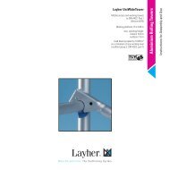
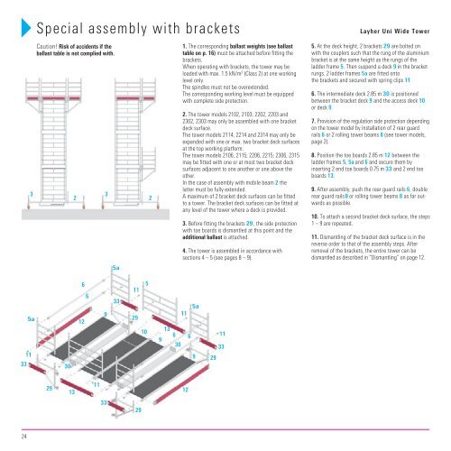
Special assembly with brackets <strong>Layher</strong> <strong>Uni</strong> <strong>Wide</strong> Tower<br />
Caution! Risk of accidents if the<br />
ballast table is not complied with.<br />
29<br />
30<br />
13<br />
2<br />
6<br />
12<br />
6<br />
11<br />
3<br />
9<br />
33<br />
5a<br />
33<br />
11<br />
29<br />
29<br />
5<br />
10<br />
2<br />
13<br />
6<br />
9<br />
30<br />
1. The corresponding ballast weights (see ballast<br />
table on p. 16) must be attached before fitting the<br />
brackets.<br />
When operating with brackets, the tower may be<br />
loaded with max. 1.5 kN/m 2 (Class 2) at one working<br />
level only.<br />
The spindles must not be overextended.<br />
The corresponding working level must be equipped<br />
with complete side protection.<br />
2. The tower models 2102, 2103; 2202, 2203 and<br />
2302, 2303 may only be assembled with one bracket<br />
deck surface.<br />
The tower models 2114, 2214 and 2314 may only be<br />
expanded with one or max. two bracket deck surfaces<br />
at the top working platform.<br />
The tower models 2106, 2115; 2206, 2215; 2306, 2315<br />
may be fitted with one or at most two bracket deck<br />
surfaces adjacent to one another or one above the<br />
other.<br />
In the case of assembly with mobile beam 2 the<br />
latter must be fully extended.<br />
A maximum of 2 bracket deck surfaces can be fitted<br />
to a tower. The bracket deck surfaces can be fitted at<br />
any level of the tower where a deck is provided.<br />
3. Before fitting the brackets 29 , the side protection<br />
with toe boards is dismantled at this point and the<br />
additional ballast is attached.<br />
4. The tower is assembled in accordance with<br />
sections 4 – 5 (see pages 8 – 9).<br />
11<br />
12<br />
6<br />
5a<br />
9<br />
29<br />
11<br />
33<br />
5. At the deck height, 2 brackets 29 are bolted on<br />
with the couplers such that the rung of the aluminium<br />
bracket is at the same height as the rungs of the<br />
ladder frame 5. Then suspend a deck 9 in the bracket<br />
rungs. 2 ladder frames 5a are fitted onto<br />
the brackets and secured with spring clips 11.<br />
6. The intermediate deck 2.85 m 30 is positioned<br />
between the bracket deck 9 and the access deck 10<br />
or deck 9.<br />
7. Provision of the regulation side protection depending<br />
on the tower model by installation of 2 rear guard<br />
rails 6 or 2 rolling tower beams 8 (see tower models,<br />
page 2).<br />
8. Position the toe boards 2.85 m 12 between the<br />
ladder frames 5, 5a and 6 and secure them by<br />
inserting 2 end toe boards 0.75 m 33 and 2 end toe<br />
boards 13 .<br />
9. After assembly, push the rear guard rails 6, double<br />
rear guard rails 8 or rolling tower beams 8 as far outwards<br />
as possible.<br />
10. To attach a second bracket deck surface, the steps<br />
1 – 9 are repeated.<br />
11. Dismantling of the bracket deck surface is in the<br />
reverse order to that of the assembly steps. After<br />
removal of the brackets, the entire tower can be<br />
dismantled as described in “Dismantling „ on page 12.