
Create successful ePaper yourself
Turn your PDF publications into a flip-book with our unique Google optimized e-Paper software.
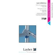
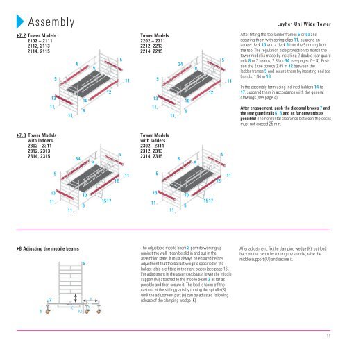
Assembly <strong>Layher</strong> <strong>Uni</strong> <strong>Wide</strong> Tower<br />
�7.2 Tower Models<br />
2102 – 2111<br />
2112, 2113<br />
2114, 2115<br />
13<br />
11<br />
5<br />
11<br />
34<br />
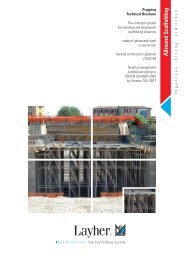
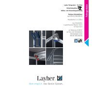
�8 Adjusting the mobile beams<br />
1<br />
2<br />
13<br />
11<br />
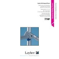
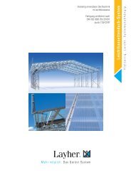
�7.3 Tower Models<br />
with ladders<br />
2302 – 2311<br />
2312, 2313<br />
2314, 2315<br />
5<br />
11<br />
8<br />
10<br />
6<br />
10<br />
6<br />
5<br />
K M S<br />
V<br />
9<br />
9<br />
12<br />
15 17<br />
12<br />
5<br />
5<br />
11<br />
11<br />
Tower Models<br />
2202 – 2211<br />
2212, 2213<br />
2214, 2215<br />
13<br />
11<br />
13<br />
11<br />
5<br />
Tower Models<br />
with ladders<br />
2302 – 2311<br />
2312, 2313<br />
2314, 2315<br />
5<br />
11<br />
11<br />
34<br />
8<br />
10<br />
6<br />
10<br />
6<br />
The adjustable mobile beam 2 permits working up<br />
against the wall. It can be slid in and out in the<br />
assembled state. It must always be ensured before<br />
adjustment that the ballast weights specified in the<br />
ballast table are fitted in the right places (see page 16).<br />
For adjustment in the assembled state, lower the middle<br />
support (M) attached to the mobile beam 2 as far as<br />
possible and then secure it. The load is taken off the<br />
castors at the sliding parts by turning the spindle (S)<br />
until the adjustment part (V) can be adjusted following<br />
release of the clamping wedge (K).<br />
9<br />
9<br />
12<br />
15 17<br />
12<br />
5<br />
5<br />
11<br />
11<br />
After fitting the top ladder frames 5 or 5a and<br />
securing them with spring clips 11, suspend an<br />
access deck 10 and a deck 9 into the 5th rung from<br />
the top. The regulation side protection to match the<br />
tower model is made by installing 2 double rear guard<br />
rails 8 or 2 beams, 2.85 m 34 (see pages 2 – 4). Position<br />
the 2 toe boards 2.85 m 12 between the<br />
ladder frames 5 and secure them by inserting end toe<br />
boards, 1.44 m 13.<br />
In the assembly form using inclined ladders 14 to<br />
17, suspend them in accordance with the general<br />
drawings (see page 4).<br />
After engagement, push the diagonal braces 7 and<br />
the rear guard rails 6 , 8 and as far outwards as<br />
possible! The horizontal clearance between the decks<br />
must not exceed 25 mm.<br />
After adjustment, fix the clamping wedge (K), put load<br />
back on the castor by turning the spindle, raise the<br />
middle support (M) and secure it.<br />
11