
Create successful ePaper yourself
Turn your PDF publications into a flip-book with our unique Google optimized e-Paper software.
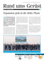
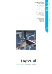
Assembly <strong>Layher</strong> <strong>Uni</strong> <strong>Wide</strong> Tower<br />
�1 Observe the general instructions for assembly and use on page 32. The examples of assembly shown for tower models 2108 – 2111, 2128 – 2131, 2148 –<br />
2151, 2208 – 2211 and 2308 – 2311 (see pages 2 – 6) are intended for use indoors and enclosed on all sides. In accordance with the regulations as amended<br />
with effect from 1 January 1987, the platform height outdoors is max. 8 m. The material and ballast tables on pages 14 – 16 must be complied with.<br />
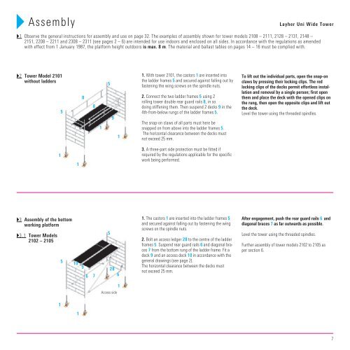
�2 Tower Model 2101<br />
without ladders<br />
�3 Assembly of the bottom<br />
working platform<br />
�3.1 Tower Models<br />
2102 – 2105<br />
1<br />
1<br />
5<br />
5<br />
1<br />
8<br />
10<br />
9<br />
1<br />
6<br />
8<br />
7<br />
1<br />
5<br />
5<br />
9<br />
1<br />
28<br />
6<br />
Access side<br />
1<br />
1. With tower 2101, the castors 1 are inserted into<br />
the ladder frames 5 and secured against falling out by<br />
fastening the wing screws on the spindle nuts.<br />
2. Connect the two ladder frames 5 using 2<br />
rolling tower double rear guard rails 8 , in so<br />
doing stiffening them. Then suspend 2 decks 9 in the<br />
4th-from-below rungs of the ladder frames 5.<br />
The snap-on claws of all parts must here be<br />
snapped on from above into the ladder frames 5.<br />
The horizontal clearance between the decks must<br />
not exceed 25 mm.<br />
3. A three-part side protection must be fitted if<br />
required by the regulations applicable for the specific<br />
work being performed.<br />
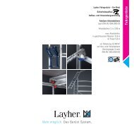
1. The castors 1 are inserted into the ladder frames 5<br />
and secured against falling out by fastening the wing<br />
screws on the spindle nuts.<br />
2. Bolt an access ledger 28 to the centre of the ladder<br />
frames 5. Suspend rear guard rails 6 and diagonal braces<br />
7 from the bottom rung of the ladder frame. Fit a<br />
deck 9 and an access deck 10 in accordance with the<br />
general drawings (see page 2).<br />
The horizontal clearance between the decks must<br />
not exceed 25 mm.<br />
To lift out the individual parts, open the snap-on<br />
claws by pressing their locking clips. The red<br />
locking clips of the decks permit effortless installation<br />
and removal by a single person; first open<br />
them and place the deck with the opened clips on<br />
the rung, then open the opposite clips and lift out<br />
the deck.<br />
Level the tower using the threaded spindles.<br />
After engagement, push the rear guard rails 6 and<br />
diagonal braces 7 as far outwards as possible.<br />
Level the tower using the threaded spindles.<br />
Further assembly of tower models 2102 to 2105 as<br />
per section 6.<br />
7