
Create successful ePaper yourself
Turn your PDF publications into a flip-book with our unique Google optimized e-Paper software.
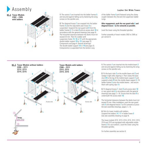
Assembly <strong>Layher</strong> <strong>Uni</strong> <strong>Wide</strong> Tower<br />
5<br />
�5.2 Tower Models<br />
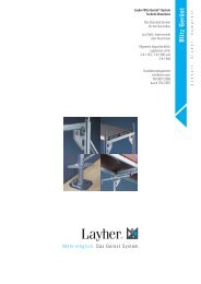
1. The castors 1 are inserted into the ladder frames 5 of the ladder frame 5 and fastened using the clamp<br />
2302 – 2305<br />
and secured against falling out by fastening the wing coupler between the 2nd and 3rd suspension ladder<br />
with ladders<br />
screws on the spindle nuts.<br />
rungs.<br />
5 10<br />
9 14<br />
19<br />
2. The diagonal braces 7 are snapped into the ladder<br />
frames 5 and the adjustable plan brace 4 is<br />
suspended. Suspend the rear guard rail 6 from the<br />
After engagement, push the rear guard rails 6 and<br />
diagonal braces 7 as far outwards as possible.<br />
4<br />
6<br />
ladder frames 5. Fit a deck 9 and an access deck 10 in Level the tower using the threaded spindles.<br />
7<br />
1<br />
accordance with the general drawings (see page 4).<br />
The horizontal clearance between the decks must not<br />
exceed 25 mm. Then fit a ladder with<br />
suspension hooks 14 , 16 or 17 with the appropriate<br />
Further assembly of tower models 2302 to 2305 as<br />
per section 6.<br />
1<br />
double ladder support 18 or 19 (see page 22,<br />
Components and page 4, General drawings).<br />
1<br />
The double ladder support 18 or 19 (see page 22,<br />
Components) is suspended from the bottom rung<br />
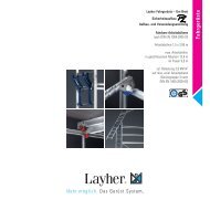
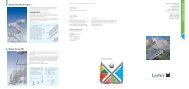
�5.3 Tower Models without ladders<br />
2206 – 2211<br />
2212, 2213<br />
2214, 2215<br />
6<br />
�3<br />
11<br />
Wedge<br />
after fitting<br />
�2<br />
5<br />
1<br />
10<br />
11<br />
9<br />
2<br />
9<br />
3<br />
1<br />
6<br />
20<br />
7<br />
Access side<br />
5<br />
11<br />
2<br />
1<br />
Tower Models with ladders<br />
2306 – 2311<br />
2312, 2313<br />
2314, 2315<br />
6<br />
11<br />
1<br />
5<br />
9<br />
11<br />
10<br />
2<br />
9<br />
3<br />
6<br />
7<br />
1<br />
20<br />
14<br />
Access side<br />
5<br />
11<br />
2<br />
1<br />
1. The castors 1 are inserted into the mobile beam 2<br />
and secured against falling out by fastening the wing<br />
screws on the spindle nuts.<br />
2. Fit the basic tube 3 at the mobile beam end 2 and<br />
wedge it tight after aligning it. Then clamp the base<br />
strut 20 to the leg of the mobile beam support 2 and<br />
suspend a deck 9 from the mobile beam support 2. Fit<br />
ladder frames 5 onto the mobile beams and secure<br />
them with spring clips 11.<br />
3. Fit diagonal braces 7, deck 9 and access deck 10<br />
or rear guard rails 6 in accordance with the general<br />
drawings (see page 2 + 4). Ensure that the deck 9 is<br />
underneath the access deck 10.<br />
The horizontal clearance between the decks must not<br />
exceed 25 mm. After installation, push the rear guard<br />
rails 6 and diagonal braces 7 as far outwards as possible<br />
(see assembly drawings, pages 2 + 4).<br />
4. Only for tower models with ladders.<br />
Suspend the ladders 14 , 17 in ladder frame 5<br />
(see also assembly drawing on page 4).<br />
The tower models 2212, 2213, 2214, 2215, 2312, 2313,<br />
2314 and 2315 are equipped with adjustable mobile<br />
beams 2 for use outdoors. Level the tower using the<br />
threaded spindles.<br />
For further assembly see section 6.<br />
9